CN111404247A - Battery energy processing device and method and vehicle - Google Patents
Battery energy processing device and method and vehicleDownload PDFInfo
- Publication number
- CN111404247A CN111404247ACN202010502046.9ACN202010502046ACN111404247ACN 111404247 ACN111404247 ACN 111404247ACN 202010502046 ACN202010502046 ACN 202010502046ACN 111404247 ACN111404247 ACN 111404247A
- Authority
- CN
- China
- Prior art keywords
- battery
- bridge arm
- energy
- phase bridge
- switch
- Prior art date
- Legal status (The legal status is an assumption and is not a legal conclusion. Google has not performed a legal analysis and makes no representation as to the accuracy of the status listed.)
- Granted
Links
Images


Classifications
- B—PERFORMING OPERATIONS; TRANSPORTING
- B60—VEHICLES IN GENERAL
- B60L—PROPULSION OF ELECTRICALLY-PROPELLED VEHICLES; SUPPLYING ELECTRIC POWER FOR AUXILIARY EQUIPMENT OF ELECTRICALLY-PROPELLED VEHICLES; ELECTRODYNAMIC BRAKE SYSTEMS FOR VEHICLES IN GENERAL; MAGNETIC SUSPENSION OR LEVITATION FOR VEHICLES; MONITORING OPERATING VARIABLES OF ELECTRICALLY-PROPELLED VEHICLES; ELECTRIC SAFETY DEVICES FOR ELECTRICALLY-PROPELLED VEHICLES
- B60L53/00—Methods of charging batteries, specially adapted for electric vehicles; Charging stations or on-board charging equipment therefor; Exchange of energy storage elements in electric vehicles
- B60L53/20—Methods of charging batteries, specially adapted for electric vehicles; Charging stations or on-board charging equipment therefor; Exchange of energy storage elements in electric vehicles characterised by converters located in the vehicle
- B60L53/24—Using the vehicle's propulsion converter for charging
- B—PERFORMING OPERATIONS; TRANSPORTING
- B60—VEHICLES IN GENERAL
- B60L—PROPULSION OF ELECTRICALLY-PROPELLED VEHICLES; SUPPLYING ELECTRIC POWER FOR AUXILIARY EQUIPMENT OF ELECTRICALLY-PROPELLED VEHICLES; ELECTRODYNAMIC BRAKE SYSTEMS FOR VEHICLES IN GENERAL; MAGNETIC SUSPENSION OR LEVITATION FOR VEHICLES; MONITORING OPERATING VARIABLES OF ELECTRICALLY-PROPELLED VEHICLES; ELECTRIC SAFETY DEVICES FOR ELECTRICALLY-PROPELLED VEHICLES
- B60L58/00—Methods or circuit arrangements for monitoring or controlling batteries or fuel cells, specially adapted for electric vehicles
- B60L58/10—Methods or circuit arrangements for monitoring or controlling batteries or fuel cells, specially adapted for electric vehicles for monitoring or controlling batteries
- B60L58/24—Methods or circuit arrangements for monitoring or controlling batteries or fuel cells, specially adapted for electric vehicles for monitoring or controlling batteries for controlling the temperature of batteries
- B60L58/27—Methods or circuit arrangements for monitoring or controlling batteries or fuel cells, specially adapted for electric vehicles for monitoring or controlling batteries for controlling the temperature of batteries by heating
- H—ELECTRICITY
- H01—ELECTRIC ELEMENTS
- H01M—PROCESSES OR MEANS, e.g. BATTERIES, FOR THE DIRECT CONVERSION OF CHEMICAL ENERGY INTO ELECTRICAL ENERGY
- H01M10/00—Secondary cells; Manufacture thereof
- H01M10/42—Methods or arrangements for servicing or maintenance of secondary cells or secondary half-cells
- H01M10/44—Methods for charging or discharging
- H—ELECTRICITY
- H01—ELECTRIC ELEMENTS
- H01M—PROCESSES OR MEANS, e.g. BATTERIES, FOR THE DIRECT CONVERSION OF CHEMICAL ENERGY INTO ELECTRICAL ENERGY
- H01M10/00—Secondary cells; Manufacture thereof
- H01M10/60—Heating or cooling; Temperature control
- H01M10/61—Types of temperature control
- H01M10/615—Heating or keeping warm
- Y—GENERAL TAGGING OF NEW TECHNOLOGICAL DEVELOPMENTS; GENERAL TAGGING OF CROSS-SECTIONAL TECHNOLOGIES SPANNING OVER SEVERAL SECTIONS OF THE IPC; TECHNICAL SUBJECTS COVERED BY FORMER USPC CROSS-REFERENCE ART COLLECTIONS [XRACs] AND DIGESTS
- Y02—TECHNOLOGIES OR APPLICATIONS FOR MITIGATION OR ADAPTATION AGAINST CLIMATE CHANGE
- Y02E—REDUCTION OF GREENHOUSE GAS [GHG] EMISSIONS, RELATED TO ENERGY GENERATION, TRANSMISSION OR DISTRIBUTION
- Y02E60/00—Enabling technologies; Technologies with a potential or indirect contribution to GHG emissions mitigation
- Y02E60/10—Energy storage using batteries
- Y—GENERAL TAGGING OF NEW TECHNOLOGICAL DEVELOPMENTS; GENERAL TAGGING OF CROSS-SECTIONAL TECHNOLOGIES SPANNING OVER SEVERAL SECTIONS OF THE IPC; TECHNICAL SUBJECTS COVERED BY FORMER USPC CROSS-REFERENCE ART COLLECTIONS [XRACs] AND DIGESTS
- Y02—TECHNOLOGIES OR APPLICATIONS FOR MITIGATION OR ADAPTATION AGAINST CLIMATE CHANGE
- Y02T—CLIMATE CHANGE MITIGATION TECHNOLOGIES RELATED TO TRANSPORTATION
- Y02T10/00—Road transport of goods or passengers
- Y02T10/60—Other road transportation technologies with climate change mitigation effect
- Y02T10/70—Energy storage systems for electromobility, e.g. batteries
- Y—GENERAL TAGGING OF NEW TECHNOLOGICAL DEVELOPMENTS; GENERAL TAGGING OF CROSS-SECTIONAL TECHNOLOGIES SPANNING OVER SEVERAL SECTIONS OF THE IPC; TECHNICAL SUBJECTS COVERED BY FORMER USPC CROSS-REFERENCE ART COLLECTIONS [XRACs] AND DIGESTS
- Y02—TECHNOLOGIES OR APPLICATIONS FOR MITIGATION OR ADAPTATION AGAINST CLIMATE CHANGE
- Y02T—CLIMATE CHANGE MITIGATION TECHNOLOGIES RELATED TO TRANSPORTATION
- Y02T10/00—Road transport of goods or passengers
- Y02T10/60—Other road transportation technologies with climate change mitigation effect
- Y02T10/7072—Electromobility specific charging systems or methods for batteries, ultracapacitors, supercapacitors or double-layer capacitors
- Y—GENERAL TAGGING OF NEW TECHNOLOGICAL DEVELOPMENTS; GENERAL TAGGING OF CROSS-SECTIONAL TECHNOLOGIES SPANNING OVER SEVERAL SECTIONS OF THE IPC; TECHNICAL SUBJECTS COVERED BY FORMER USPC CROSS-REFERENCE ART COLLECTIONS [XRACs] AND DIGESTS
- Y02—TECHNOLOGIES OR APPLICATIONS FOR MITIGATION OR ADAPTATION AGAINST CLIMATE CHANGE
- Y02T—CLIMATE CHANGE MITIGATION TECHNOLOGIES RELATED TO TRANSPORTATION
- Y02T90/00—Enabling technologies or technologies with a potential or indirect contribution to GHG emissions mitigation
- Y02T90/10—Technologies relating to charging of electric vehicles
- Y02T90/14—Plug-in electric vehicles
Landscapes
- Engineering & Computer Science (AREA)
- Power Engineering (AREA)
- Transportation (AREA)
- Mechanical Engineering (AREA)
- Chemical Kinetics & Catalysis (AREA)
- Manufacturing & Machinery (AREA)
- Chemical & Material Sciences (AREA)
- Electrochemistry (AREA)
- General Chemical & Material Sciences (AREA)
- Sustainable Development (AREA)
- Sustainable Energy (AREA)
- Life Sciences & Earth Sciences (AREA)
- Charge And Discharge Circuits For Batteries Or The Like (AREA)
Abstract
Translated fromChinese
Description
Translated fromChinese技术领域technical field
本申请涉及车辆领域,具体地,涉及一种电池能量处理装置、方法及车辆。The present application relates to the field of vehicles, and in particular, to a battery energy processing device, method, and vehicle.
背景技术Background technique
当电池处于低温状态时,需要对电池进行自加热。而如果此时电池还需要充电的话,就需要等待自加热完成之后再进行插枪操作,充电桩才可对电池进行充电。因此亟需解决如何在自加热期间能够对电池进行充电的问题。When the battery is in a low temperature state, self-heating of the battery is required. If the battery still needs to be charged at this time, you need to wait for the self-heating to complete before inserting the gun, and the charging pile can charge the battery. Therefore, there is an urgent need to solve the problem of how to charge the battery during self-heating.
发明内容SUMMARY OF THE INVENTION
本申请的目的是提供一种电池能量处理装置、方法及车辆。The purpose of the present application is to provide a battery energy processing device, method and vehicle.
为了实现上述目的,第一方面,本申请提供一种电池能量处理装置,包括:能量交换接口;降压充电电路,包括:M相桥臂,所述M相桥臂的第一汇流端连接所述能量交换接口的正极,所述M相桥臂的第二汇流端、所述电池的负极分别与所述能量交换接口的负极连接,其中,M≥1;M个线圈,所述M个线圈的第一端一一对应连接至所述M相桥臂的中点,所述M个线圈的第二端连接所述电池的正极;第一电容,所述第一电容的第一端与所述M相桥臂的第一汇流端连接,所述第一电容的第二端与所述M相桥臂的所述第二汇流端连接;电池振荡加热电路,所述电池振荡加热电路与所述电池连接;控制器,被配置为在第一预设状态下,控制所述电池振荡加热电路与所述电池进行充电和放电,以实现对所述电池的加热,以及控制所述降压充电电路接收来自所述能量交换接口的能量输出至所述电池,以实现对所述电池的充电。In order to achieve the above object, in the first aspect, the present application provides a battery energy processing device, including: an energy exchange interface; a step-down charging circuit, including: an M-phase bridge arm, the first bus end of the M-phase bridge arm is connected to a The positive pole of the energy exchange interface, the second bus terminal of the M-phase bridge arm, and the negative pole of the battery are respectively connected to the negative pole of the energy exchange interface, wherein M≥1; M coils, the M coils The first ends of the M coils are connected to the midpoint of the M-phase bridge arms in a one-to-one correspondence, and the second ends of the M coils are connected to the positive pole of the battery; the first capacitor, the first end of the first capacitor is connected to the The first confluence end of the M-phase bridge arm is connected, the second end of the first capacitor is connected with the second confluence end of the M-phase bridge arm; the battery oscillating heating circuit is connected to the battery oscillating heating circuit. the battery is connected; the controller is configured to control the battery oscillating heating circuit to charge and discharge the battery in a first preset state, so as to realize the heating of the battery, and control the step-down charging The circuit receives the energy output from the energy exchange interface to the battery, so as to realize the charging of the battery.
在具体实施例中,在第一预设状态下,控制器控制所述电池振荡加热电路中的储能单元与电池进行充电和放电以实现对电池的加热。上述使储能单元与电池进行充电和放电是指电池向储能单元提供能量,使电池放电,以及储能单元向电池提供能量,使电池充电。In a specific embodiment, in the first preset state, the controller controls the energy storage unit in the battery oscillating heating circuit to charge and discharge the battery to achieve heating of the battery. The above-mentioned charging and discharging the energy storage unit and the battery means that the battery provides energy to the energy storage unit to discharge the battery, and the energy storage unit provides energy to the battery to charge the battery.
可选地,所述装置还包括第一开关,所述第一开关的第一端与所述能量交换接口的正极连接,所述第一开关的第二端连接至所述电池的正极;所述控制器,还被配置为在第二预设状态下,控制所述电池振荡加热电路中的储能单元处于不与所述电池进行充电和放电的状态且所述降压充电电路处于不接收来自所述能量交换接口的能量的状态,并控制所述第一开关闭合,以使所述电池直接接收来自所述能量交换接口的能量。Optionally, the device further includes a first switch, the first end of the first switch is connected to the positive pole of the energy exchange interface, and the second end of the first switch is connected to the positive pole of the battery; the The controller is further configured to, in a second preset state, control the energy storage unit in the battery oscillating heating circuit to be in a state of not charging and discharging with the battery and the step-down charging circuit in a state of not receiving state of the energy from the energy exchange interface, and control the first switch to be closed, so that the battery directly receives the energy from the energy exchange interface.
可选地,所述电池振荡加热电路包括N相桥臂;所述储能单元包括N个线圈和第二电容,所述N个线圈的第一端一一对应连接至所述N相桥臂的中点,所述N个线圈的第二端共接并连接至所述电池的正极,所述第二电容的第一端与所述N相桥臂的第一汇流端连接,所述第二电容的第二端、所述N相桥臂的第二汇流端均与所述电池的负极连接;其中,N≥1。Optionally, the battery oscillating heating circuit includes an N-phase bridge arm; the energy storage unit includes N coils and a second capacitor, and the first ends of the N coils are connected to the N-phase bridge arm in a one-to-one correspondence. the midpoint of the N coils, the second ends of the N coils are commonly connected and connected to the positive electrode of the battery, the first end of the second capacitor is connected to the first bus end of the N-phase bridge arm, the The second end of the two capacitors and the second bus end of the N-phase bridge arm are all connected to the negative electrode of the battery; wherein, N≧1.
可选地,所述N个线圈为电机绕组,所述N相桥臂为桥臂变换器;所述装置还包括:第二开关,所述第二开关的第一端与所述电池的正极连接,所述第二开关的第二端与所述第二电容的第一端连接;第三开关,所述第三开关的第一端与所述电池的正极连接,所述第三开关的第二端与所述N个线圈的第二端连接;所述控制器,被配置为在第一预设状态下,控制所述第二开关断开、所述第三开关闭合,并控制所述电池振荡加热电路中的储能单元与所述电池进行充电和放电,以实现对所述电池的加热,以及控制所述M相桥臂使所述电池接收来自所述能量交换接口的能量,以实现对所述电池的充电;所述控制器,还被配置为在第三预设状态下,控制所述第二开关闭合、所述第三开关断开,并控制所述桥臂变换器使与所述电机绕组对应的电机输出功率。Optionally, the N coils are motor windings, and the N-phase bridge arm is a bridge arm converter; the device further includes: a second switch, the first end of the second switch is connected to the positive pole of the battery connection, the second end of the second switch is connected to the first end of the second capacitor; the third switch, the first end of the third switch is connected to the positive electrode of the battery, the third switch The second end is connected to the second ends of the N coils; the controller is configured to, in a first preset state, control the second switch to open, the third switch to close, and to control all the The energy storage unit in the battery oscillating heating circuit is charged and discharged with the battery to achieve heating of the battery, and the M-phase bridge arm is controlled so that the battery receives energy from the energy exchange interface, so as to charge the battery; the controller is further configured to, in a third preset state, control the second switch to close, the third switch to open, and to control the bridge arm converter The motor corresponding to the motor winding is made to output power.
可选地,所述电池振荡加热电路包括N相桥臂,所述N相桥臂的第一汇流端连接所述电池的正极,所述N相桥臂的第二汇流端连接所述电池的负极;所述储能单元包括N个线圈和第三电容,所述N个线圈的第一端一一对应连接至所述N相桥臂的中点,所述N个线圈的第二端共接所述第三电容的第一端与所述N个线圈的第二端连接,所述第三电容的第二端与所述N相桥臂的第二汇流端连接;其中,N≥1。Optionally, the battery oscillating heating circuit includes an N-phase bridge arm, the first bus terminal of the N-phase bridge arm is connected to the positive electrode of the battery, and the second bus terminal of the N-phase bridge arm is connected to the battery. negative electrode; the energy storage unit includes N coils and a third capacitor, the first ends of the N coils are connected to the midpoint of the N-phase bridge arm in a one-to-one correspondence, and the second ends of the N coils are in common The first end of the third capacitor is connected to the second ends of the N coils, and the second end of the third capacitor is connected to the second bus end of the N-phase bridge arm; wherein, N≥1 .
可选地,所述N个线圈为电机绕组,所述N相桥臂为桥臂变换器;所述装置还包括:第四开关,其中,所述第四开关的第一端与所述N个线圈的第二端连接,所述第四开关的第二端与所述第三电容的第一端连接;所述控制器,被配置为在第一预设状态下,控制所述第四开关闭合,并控制所述电池振荡加热电路中的储能单元与所述电池进行充电和放电,以实现对所述电池的加热,以及控制所述M相桥臂使所述电池接收来自所述能量交换接口的能量,以实现对所述电池的充电;所述控制器,还被配置为在第三预设状态下,控制所述第四开关断开,并控制所述桥臂变换器使与所述电机绕组对应的电机输出功率。Optionally, the N coils are motor windings, and the N-phase bridge arm is a bridge arm converter; the device further includes: a fourth switch, wherein a first end of the fourth switch is connected to the N-phase bridge arm. The second end of each of the coils is connected, and the second end of the fourth switch is connected to the first end of the third capacitor; the controller is configured to control the fourth switch in a first preset state The switch is closed, and the energy storage unit in the battery oscillating heating circuit is controlled to charge and discharge with the battery, so as to realize the heating of the battery, and the M-phase bridge arm is controlled so that the battery receives electricity from the battery. The energy of the energy exchange interface is used to realize the charging of the battery; the controller is further configured to control the fourth switch to be disconnected in a third preset state, and to control the bridge arm converter to enable The motor output power corresponding to the motor winding.
可选地,所述装置还包括:第五开关,所述第五开关的第一端与所述能量交换接口的正极连接,所述第五开关的第二端与所述第三电容的第一端连接;所述控制器,还被配置为在第四预设状态,控制所述降压充电电路处于不接收来自所述能量交换接口的能量的状态,并控制所述第四开关和所述第五开关闭合,以及控制所述N相桥臂使所述电池接收来自所述能量交换接口的能量,其中,所述能量交换接口的能量通过所述N相桥臂、所述N个线圈和所述第三电容升压后被所述电池接收。Optionally, the device further includes: a fifth switch, a first end of the fifth switch is connected to the positive pole of the energy exchange interface, and a second end of the fifth switch is connected to the first end of the third capacitor. one end is connected; the controller is further configured to, in a fourth preset state, control the step-down charging circuit to be in a state of not receiving energy from the energy exchange interface, and control the fourth switch and all the fifth switch is closed, and the N-phase bridge arm is controlled so that the battery receives energy from the energy exchange interface, wherein the energy of the energy exchange interface passes through the N-phase bridge arm, the N coils and the third capacitor is boosted and received by the battery.
可选地,所述控制器还被配置为,在第五预设状态下,控制第四开关和第五开关导通,并控制所述N相桥臂的下桥臂关断,使所述电池直接接收来自所述能量交换接口的能量。Optionally, the controller is further configured to, in a fifth preset state, control the fourth switch and the fifth switch to turn on, and control the lower bridge arm of the N-phase bridge arm to turn off, so that the The battery receives energy directly from the energy exchange interface.
可选地,所述电池振荡加热电路包括N相桥臂,其中,所述N相桥臂的第一汇流端连接所述电池的正极,所述N相桥臂的第二汇流端连接所述电池的负极;所述储能单元包括N个线圈,所述N个线圈的第一端一一对应连接至所述N相桥臂的中点,所述N个线圈的第二端共接,所述N相桥臂的第二汇流端连接至所述电池的负极;其中,N≥2。Optionally, the battery oscillating heating circuit includes an N-phase bridge arm, wherein a first bus terminal of the N-phase bridge arm is connected to the positive electrode of the battery, and a second bus terminal of the N-phase bridge arm is connected to the The negative electrode of the battery; the energy storage unit includes N coils, the first ends of the N coils are connected to the midpoints of the N-phase bridge arms in a one-to-one correspondence, and the second ends of the N coils are connected in common, The second bus terminal of the N-phase bridge arm is connected to the negative electrode of the battery; wherein, N≧2.
可选地,所述M个线圈为压缩机的电机绕组,所述M相桥臂为压缩机的桥臂变换器;所述装置还包括第六开关,所述第六开关的第一端与所述M个线圈的第二端连接,所述第六开关的第二端与所述电池的正极连接;所述控制器,被配置为在第一预设状态下,控制所述第六开关闭合并控制所述电池振荡加热电路中的储能单元与所述电池进行充电和放电,以实现对所述电池的加热,以及控制所述M相桥臂使所述电池接收来自所述能量交换接口的能量,以实现对所述电池的充电;所述控制器,还被配置为在第六预设状态下,控制所述第六开关闭合,并控制所述降压充电电路处于不接收来自所述能量交换接口的能量的状态,以及控制所述桥臂变换器使与所述电机绕组对应的电机输出功率。Optionally, the M coils are motor windings of a compressor, and the M-phase bridge arm is a bridge arm converter of the compressor; the device further includes a sixth switch, the first end of the sixth switch is connected to the bridge arm of the compressor. The second ends of the M coils are connected, and the second end of the sixth switch is connected to the positive electrode of the battery; the controller is configured to control the sixth switch in a first preset state. Turn off and control the energy storage unit in the battery oscillating heating circuit to charge and discharge the battery to achieve heating of the battery, and control the M-phase bridge arm to make the battery receive energy from the energy exchange interface energy to charge the battery; the controller is further configured to control the sixth switch to be closed in a sixth preset state, and to control the step-down charging circuit to not receive power from The state of the energy of the energy exchange interface, and controlling the bridge arm converter to make the motor output power corresponding to the motor winding.
第二方面,本申请提供一种电池能量处理方法,在第一预设状态下,控制电池振荡加热电路与电池进行充电和放电,以实现对所述电池的加热,以及控制降压充电电路接收来自能量交换接口的能量输出至所述电池,以实现对所述电池的充电;其中,所述降压充电电路,包括:M相桥臂,所述M相桥臂的第一汇流端连接所述能量交换接口的正极,所述M相桥臂的第二汇流端、所述电池的负极分别与所述能量交换接口的负极连接,其中,M≥1;M个线圈,所述M个线圈的第一端一一对应连接至所述M相桥臂的中点,所述M个线圈的第二端连接所述电池的正极;第一电容,所述第一电容的第一端与所述M相桥臂的第一汇流端连接,所述第一电容的第二端与所述M相桥臂的所述第二汇流端连接;所述电池振荡加热电路与所述电池连接。In a second aspect, the present application provides a battery energy processing method. In a first preset state, the battery oscillating heating circuit is controlled to charge and discharge the battery to achieve heating of the battery, and the step-down charging circuit is controlled to receive The energy from the energy exchange interface is output to the battery, so as to realize the charging of the battery; wherein, the step-down charging circuit includes: an M-phase bridge arm, and the first bus end of the M-phase bridge arm is connected to the The positive pole of the energy exchange interface, the second bus terminal of the M-phase bridge arm, and the negative pole of the battery are respectively connected to the negative pole of the energy exchange interface, wherein M≥1; M coils, the M coils The first ends of the M coils are connected to the midpoint of the M-phase bridge arms in a one-to-one correspondence, and the second ends of the M coils are connected to the positive pole of the battery; the first capacitor, the first end of the first capacitor is connected to the The first bus terminal of the M-phase bridge arm is connected, the second terminal of the first capacitor is connected to the second bus terminal of the M-phase bridge arm; the battery oscillation heating circuit is connected to the battery.
在具体实施例中,在第一预设状态下,控制器控制所述电池振荡加热电路中的储能单元与电池进行充电和放电以实现对电池的加热。上述使储能单元与电池进行充电和放电是指电池向储能单元提供能量,使电池放电,以及储能单元向电池提供能量,使电池充电。In a specific embodiment, in the first preset state, the controller controls the energy storage unit in the battery oscillating heating circuit to charge and discharge the battery to achieve heating of the battery. The above-mentioned charging and discharging the energy storage unit and the battery means that the battery provides energy to the energy storage unit to discharge the battery, and the energy storage unit provides energy to the battery to charge the battery.
可选地,所述方法还包括:在第二预设状态下,控制所述电池振荡加热电路中的储能单元处于不与所述电池进行充电和放电的状态且所述降压充电电路处于不接收来自所述能量交换接口的能量的状态,并控制设置于所述能量交换接口的正极于所述电池的正极之间的第一开关闭合,以使所述电池直接接收来自所述能量交换接口的能量。Optionally, the method further includes: in a second preset state, controlling the energy storage unit in the battery oscillating heating circuit to be in a state of not charging and discharging with the battery and the step-down charging circuit in a state of not charging and discharging with the battery. The state of not receiving energy from the energy exchange interface, and controlling the first switch disposed between the positive pole of the energy exchange interface and the positive pole of the battery to close, so that the battery directly receives the energy from the energy exchange interface energy.
可选地,所述电池振荡加热电路包括N相桥臂;所述储能单元包括N个线圈和第二电容,所述N个线圈的第一端一一对应连接至所述N相桥臂的中点,所述N个线圈的第二端共接并连接至电池的正极,所述第二电容的第一端与所述N相桥臂的第一汇流端连接,所述第二电容的第二端、所述N相桥臂的第二汇流端均与所述电池的负极连接;其N≥1;所述N个线圈为电机绕组,所述N相桥臂为桥臂变换器;Optionally, the battery oscillating heating circuit includes an N-phase bridge arm; the energy storage unit includes N coils and a second capacitor, and the first ends of the N coils are connected to the N-phase bridge arm in a one-to-one correspondence. the midpoint of the N coils, the second ends of the N coils are connected in common and connected to the positive pole of the battery, the first end of the second capacitor is connected to the first bus terminal of the N-phase bridge arm, the second capacitor The second end of the N-phase bridge arm and the second confluence end of the N-phase bridge arm are connected to the negative electrode of the battery; N≥1; the N coils are motor windings, and the N-phase bridge arm is a bridge arm converter ;
所述在第一预设状态下,控制电池振荡加热电路中的储能单元与电池进行充电和放电,以实现对所述电池的加热,以及控制降压充电电路接收来自能量交换接口的能量输出至所述电池,以实现对所述电池的充电,包括:In the first preset state, the energy storage unit in the battery oscillating heating circuit is controlled to charge and discharge the battery to achieve heating of the battery, and the step-down charging circuit is controlled to receive the energy output from the energy exchange interface to the battery, so as to realize the charging of the battery, including:
在第一预设状态下,控制设置于所述电池的正极与所述第二电容的第一端之间的第二开关断开、设置于所述电池的正极与所述N个线圈的第二端之间的第三开关闭合,并控制所述电池振荡加热电路中的储能单元与所述电池进行充电和放电,以实现对所述电池的加热,以及控制所述M相桥臂使所述电池接收来自所述能量交换接口的能量,以实现对所述电池的充电;In the first preset state, the second switch disposed between the positive electrode of the battery and the first end of the second capacitor is controlled to be turned off, and the second switch disposed between the positive electrode of the battery and the first end of the N coils is controlled to be disconnected. The third switch between the two ends is closed, and controls the energy storage unit in the battery oscillating heating circuit to charge and discharge the battery, so as to heat the battery, and control the M-phase bridge arm to make the battery receives energy from the energy exchange interface to charge the battery;
所述方法还包括:The method also includes:
在第三预设状态下,控制所述第二开关闭合、所述第三开关,并控制所述桥臂变换器使与所述电机绕组对应的电机输出功率。In a third preset state, the second switch is controlled to be closed, the third switch is controlled, and the bridge arm converter is controlled to make the motor corresponding to the motor winding output power.
可选地,所述电池振荡加热电路包括N相桥臂,所述N相桥臂的第一汇流端连接所述电池的正极,所述N相桥臂的第二汇流端连接所述电池的负极;所述储能单元包括N个线圈和第三电容,所述N个线圈的第一端一一对应连接至所述N相桥臂的中点,所述N个线圈的第二端共接,所述第三电容的第一端与所述N个线圈的第二端连接,所述第三电容的第二端与所述N相桥臂的第二汇流端连接;N≥1;所述N个线圈为电机绕组,所述N相桥臂为桥臂变换器;Optionally, the battery oscillating heating circuit includes an N-phase bridge arm, the first bus terminal of the N-phase bridge arm is connected to the positive electrode of the battery, and the second bus terminal of the N-phase bridge arm is connected to the battery. negative electrode; the energy storage unit includes N coils and a third capacitor, the first ends of the N coils are connected to the midpoint of the N-phase bridge arm in a one-to-one correspondence, and the second ends of the N coils are in common connected, the first end of the third capacitor is connected to the second ends of the N coils, and the second end of the third capacitor is connected to the second bus end of the N-phase bridge arm; N≥1; The N coils are motor windings, and the N-phase bridge arms are bridge arm converters;
所述在第一预设状态下,控制电池振荡加热电路中的储能单元与电池进行充电和放电,以实现对所述电池的加热,以及控制降压充电电路接收来自能量交换接口的能量输出至所述电池,以实现对所述电池的充电,包括:In the first preset state, the energy storage unit in the battery oscillating heating circuit is controlled to charge and discharge the battery to achieve heating of the battery, and the step-down charging circuit is controlled to receive the energy output from the energy exchange interface to the battery, so as to realize the charging of the battery, including:
在第一预设状态下,控制设置于所述N个线圈的第二端与所述第三电容之间的第四开关闭合,并控制所述电池振荡加热电路中的储能单元与所述电池进行充电和放电,以实现对所述电池的加热,以及控制所述M相桥臂使所述电池接收来自所述能量交换接口的能量,以实现对所述电池的充电;In the first preset state, control the fourth switch disposed between the second ends of the N coils and the third capacitor to close, and control the energy storage unit in the battery oscillating heating circuit to connect with the third capacitor. charging and discharging the battery to realize the heating of the battery, and controlling the M-phase bridge arm to make the battery receive the energy from the energy exchange interface to realize the charging of the battery;
所述方法还包括:The method also includes:
在第三预设状态下,控制所述第四开关断开,并控制所述桥臂变换器使与所述电机绕组对应的电机输出功率。In a third preset state, the fourth switch is controlled to be turned off, and the bridge arm converter is controlled to make the motor corresponding to the motor winding output power.
可选地,所述方法还包括:Optionally, the method further includes:
在第四预设状态,控制所述降压充电电路处于不接收来自所述能量交换接口的能量的状态,并控制所述第四开关和设置于所述能量交换接口的正极与所述第三电容之间的第五开关闭合,以及控制所述N相桥臂使所述电池接收来自所述能量交换接口的能量,其中,所述能量交换接口的能量通过所述N相桥臂、所述N个线圈和所述第三电容升压后被所述电池接收。In a fourth preset state, the step-down charging circuit is controlled to be in a state of not receiving energy from the energy exchange interface, and the fourth switch and the positive pole disposed on the energy exchange interface and the third switch are controlled The fifth switch between the capacitors is closed, and the N-phase bridge arm is controlled so that the battery receives energy from the energy exchange interface, wherein the energy of the energy exchange interface passes through the N-phase bridge arm, the The N coils and the third capacitor are boosted and received by the battery.
可选地,所述控制器还被配置为,在第五预设状态下,控制第四开关和第五开关导通,并控制所述N相桥臂的下桥臂关断,使所述电池直接接收来自所述能量交换接口的能量。Optionally, the controller is further configured to, in a fifth preset state, control the fourth switch and the fifth switch to turn on, and control the lower bridge arm of the N-phase bridge arm to turn off, so that the The battery receives energy directly from the energy exchange interface.
可选地,所述电池振荡加热电路包括N相桥臂,所述N相桥臂的第一汇流端连接所述电池的正极,所述N相桥臂的第二汇流端连接所述电池的负极;所述储能单元包括N个线圈,所述N个线圈的第一端一一对应连接至所述N相桥臂的中点,所述N个线圈的第二端共接,所述N相桥臂的第二汇流端连接至所述电池的负极;其中,N≥2。Optionally, the battery oscillating heating circuit includes an N-phase bridge arm, the first bus terminal of the N-phase bridge arm is connected to the positive electrode of the battery, and the second bus terminal of the N-phase bridge arm is connected to the battery. negative electrode; the energy storage unit includes N coils, the first ends of the N coils are connected to the midpoints of the N-phase bridge arms in a one-to-one correspondence, the second ends of the N coils are connected in common, the The second bus terminal of the N-phase bridge arm is connected to the negative electrode of the battery; wherein, N≧2.
可选地,所述M个线圈为压缩机的电机绕组,所述M相桥臂为压缩机的桥臂变换器;Optionally, the M coils are motor windings of a compressor, and the M-phase bridge arm is a bridge arm converter of the compressor;
所述在第一预设状态下,控制电池振荡加热电路中的储能单元与电池进行充电和放电,以实现对所述电池的加热,以及控制降压充电电路接收来自能量交换接口的能量输出至所述电池,以实现对所述电池的充电,包括:In the first preset state, the energy storage unit in the battery oscillating heating circuit is controlled to charge and discharge the battery to achieve heating of the battery, and the step-down charging circuit is controlled to receive the energy output from the energy exchange interface to the battery, so as to realize the charging of the battery, including:
在第一预设状态下,控制设置于所述M个线圈的第二端和所述电池的正极之间的第六开关闭合,并控制所述电池振荡加热电路中的储能单元与所述电池进行充电和放电,以实现对所述电池的加热,以及控制所述M相桥臂使所述电池接收来自所述能量交换接口的能量,以实现对所述电池的充电;In the first preset state, the sixth switch arranged between the second ends of the M coils and the positive electrode of the battery is controlled to be closed, and the energy storage unit in the battery oscillating heating circuit is controlled to be connected to the battery. charging and discharging the battery to realize the heating of the battery, and controlling the M-phase bridge arm to make the battery receive the energy from the energy exchange interface to realize the charging of the battery;
所述方法还包括:The method also includes:
在第六预设状态,控制所述述第六开关闭合,并控制所述降压充电电路处于不接收来自所述能量交换接口的能量的状态,并控制所述第六开关闭合,以及控制所述桥臂变换器使与所述电机绕组对应的电机输出功率。In a sixth preset state, the sixth switch is controlled to be closed, and the step-down charging circuit is controlled to be in a state of not receiving energy from the energy exchange interface, and the sixth switch is controlled to be closed, and all The bridge arm converter makes the motor output power corresponding to the motor winding.
第三方面,本申请提供一种车辆,包括电池及本申请第一方面提供的所述电池能量处理装置。In a third aspect, the present application provides a vehicle, including a battery and the battery energy processing device provided in the first aspect of the present application.
通过上述技术方案,能够在控制电池振荡加热电路中的储能单元与电池进行充电和放电以实现对电池进行加热期间,控制降压充电电路接收来自能量交换接口的能量以实现对电池的充电,这样就能够在电池自加热的时候实现电池的充电。Through the above technical solution, during the period of controlling the energy storage unit in the battery oscillation heating circuit to charge and discharge the battery to realize the heating of the battery, the step-down charging circuit can be controlled to receive the energy from the energy exchange interface to realize the charging of the battery, This enables the battery to be charged while the battery is self-heating.
本申请的其他特征和优点将在随后的具体实施方式部分予以详细说明。Other features and advantages of the present application will be described in detail in the detailed description that follows.
附图说明Description of drawings
附图是用来提供对本申请的进一步理解,并且构成说明书的一部分,与下面的具体实施方式一起用于解释本申请,但并不构成对本申请的限制。在附图中:The accompanying drawings are used to provide a further understanding of the present application, and constitute a part of the specification, and together with the following specific embodiments, are used to explain the present application, but do not constitute a limitation to the present application. In the attached image:
图1是根据一示例性实施例示出的一种电池能量处理装置的结构框图。FIG. 1 is a structural block diagram of a battery energy processing device according to an exemplary embodiment.
图2是根据一示例性实施例示出的一种电池能量处理装置的电路拓扑图。FIG. 2 is a circuit topology diagram of a battery energy processing device according to an exemplary embodiment.
图3至图6是根据一示例性实施例示出的一种降压充电电路的工作原理示意图。3 to 6 are schematic diagrams illustrating the working principle of a step-down charging circuit according to an exemplary embodiment.
图7是根据一示例性实施例示出的另一种电池能量处理装置的电路拓扑图。FIG. 7 is a circuit topology diagram of another battery energy processing device according to an exemplary embodiment.
图8是根据一示例性实施例示出的另一种电池能量处理装置的电路拓扑图。FIG. 8 is a circuit topology diagram of another battery energy processing device according to an exemplary embodiment.
图9是根据一示例性实施例示出的另一种电池能量处理装置的电路拓扑图。FIG. 9 is a circuit topology diagram of another battery energy processing device according to an exemplary embodiment.
图10是根据一示例性实施例示出的另一种电池能量处理装置的电路拓扑图。FIG. 10 is a circuit topology diagram of another battery energy processing device according to an exemplary embodiment.
图11是根据一示例性实施例示出的另一种电池能量处理装置的电路拓扑图。FIG. 11 is a circuit topology diagram of another battery energy processing device according to an exemplary embodiment.
图12是根据一示例性实施例示出的另一种电池能量处理装置的电路拓扑图。FIG. 12 is a circuit topology diagram of another battery energy processing device according to an exemplary embodiment.
图13至图16是根据一示例性实施例示出的一种升压充电的工作原理示意图。13 to 16 are schematic diagrams illustrating the working principle of a boost charging according to an exemplary embodiment.
图17是根据一示例性实施例示出的另一种电池能量处理装置的电路拓扑图。FIG. 17 is a circuit topology diagram of another battery energy processing device according to an exemplary embodiment.
图18是根据一示例性实施例示出的另一种电池能量处理装置的电路拓扑图。FIG. 18 is a circuit topology diagram of another battery energy processing device according to an exemplary embodiment.
图19是根据一示例性实施例示出的另一种电池能量处理装置的电路拓扑图。FIG. 19 is a circuit topology diagram of another battery energy processing device according to an exemplary embodiment.
图20是根据一示例性实施例示出的一种电池能量处理方法的流程图。Fig. 20 is a flow chart of a battery energy processing method according to an exemplary embodiment.
具体实施方式Detailed ways
以下结合附图对本申请的具体实施方式进行详细说明。应当理解的是,此处所描述的具体实施方式仅用于说明和解释本申请,并不用于限制本申请。The specific embodiments of the present application will be described in detail below with reference to the accompanying drawings. It should be understood that the specific embodiments described herein are only used to illustrate and explain the present application, but not to limit the present application.
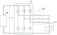
图1是根据一示例性实施例示出的一种电池能量处理装置的结构框图。如图1所示,该装置包括:能量交换接口100、降压充电电路200、电池振荡加热电路400、控制器500。其中,降压充电电路200的第一端与能量交换接口100连接,降压充电电路200的第二端与电池300连接,电池振荡加热电路400与电池300连接。控制器500,被配置为在第一预设状态下,控制电池振荡加热电路400与电池300进行充电和放电(例如循环充电和放电),以实现对电池300的加热,以及控制降压充电电路200接收来自所述能量交换接口100的能量输出至电池300,以实现对电池300的充电。上述的循环充电和放电指的是充电和放电以一定频率切换多次。FIG. 1 is a structural block diagram of a battery energy processing device according to an exemplary embodiment. As shown in FIG. 1 , the device includes: an
在第一预设状态下,控制器500控制所述电池振荡加热电路400中的储能单元与电池300进行充电和放电以实现对电池的加热。上述使储能单元与电池300进行充电和放电是指电池300向储能单元提供能量,使电池300放电,以及储能单元向电池300提供能量,使电池充电。In the first preset state, the controller 500 controls the energy storage unit in the battery oscillating
在本申请中,第一预设状态指的是电池300在执行自加热期间能够进行充电的一种状态。In the present application, the first preset state refers to a state in which the
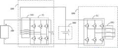
如图2所示,降压充电电路200,包括:M相桥臂B1,M相桥臂B1的第一汇流端连接能量交换接口100的正极,M相桥臂B1的第二汇流端、电池300的负极分别与能量交换接口100的负极连接,其中,M≥1;M个线圈KM1,M个线圈KM1的第一端一一对应连接至M相桥臂B1的中点,M个线圈KM1的第二端连接电池300的正极;第一电容C1,第一电容C1的第一端与M相桥臂B1的第一汇流端连接,第一电容C1的第二端与M相桥臂B1的第二汇流端连接。As shown in FIG. 2, the step-down
虽然图2是以M=3为例进行图示的,但是本领域技术人员应当理解的是,图2的桥臂数量和线圈数量仅是示例。Although FIG. 2 is illustrated with M=3 as an example, those skilled in the art should understand that the number of bridge arms and the number of coils in FIG. 2 are only examples.
通过上述技术方案,能够在控制电池振荡加热电路中的储能单元与电池进行充电和放电以实现对电池进行加热期间,控制降压充电电路接收来自能量交换接口的能量以实现对电池的充电,这样就能够在电池自加热的时候实现电池的充电。Through the above technical solution, during the period of controlling the energy storage unit in the battery oscillation heating circuit to charge and discharge the battery to realize the heating of the battery, the step-down charging circuit can be controlled to receive the energy from the energy exchange interface to realize the charging of the battery, This enables the battery to be charged while the battery is self-heating.
下面结合图3至图6详细描述在第一预设状态下降压充电电路200的工作原理。The working principle of the down-
在图3中,控制器500控制M相桥臂B1的所有上桥臂断开,M相桥臂B1的下桥臂中至少一相桥臂导通,则,电流从电池300的正极流出,依次流过M相桥臂B1中与导通的下桥臂相连接的线圈、M相桥臂B1的导通的下桥臂回到电池300的负极。这样,就能给M个线圈KM1充电。In FIG. 3 , the controller 500 controls all the upper arms of the M-phase arm B1 to be turned off, and at least one of the lower arms of the M-phase arm B1 is turned on, then the current flows from the positive electrode of the
在一个示例中,假设M相桥臂B1包括3个桥臂a1、a2和a3,线圈KM1包括3个线圈L1、L2和L3,其中,线圈L1的一端与桥臂a1的中点连接,线圈L2的一端与桥臂a2的中点连接,线圈L3与桥臂a3的中点连接。然后,将桥臂a1、a2和a3的所有上桥臂断开,将桥臂a1、a2和a3的下桥臂导通,则电池300的正极、线圈L1、线圈L2、线圈L3、桥臂a1、a2和a3的下桥臂和电池300的负极构成一个给线圈L1、线圈L2和线圈L3充电的电流循环回路。In an example, it is assumed that the M-phase bridge arm B1 includes three bridge arms a1, a2 and a3, and the coil KM1 includes three coils L1, L2 and L3, wherein one end of the coil L1 is connected to the midpoint of the bridge arm a1, and the coil One end of L2 is connected to the midpoint of the bridge arm a2, and the coil L3 is connected to the midpoint of the bridge arm a3. Then, all the upper bridge arms of the bridge arms a1, a2 and a3 are disconnected, and the lower bridge arms of the bridge arms a1, a2 and a3 are turned on, then the positive electrode of the
在图4中,控制器500控制M相桥臂B1的所有下桥臂断开,并控制M相桥臂B1的至少一个上桥臂导通,则,电流从电池300的正极流出,依次流过M个线圈KM1中与导通的上桥臂相连接的线圈、M相桥臂B1的导通的上桥臂、第一电容C1后回到电池300的负极。这样,就能够将电池300中的能量与存在线圈中的能量转移给第一电容C1,这样,就能够实现电池300和M个线圈KM1共同向第一电容C1充电。In FIG. 4 , the controller 500 controls all the lower arms of the M-phase bridge arm B1 to be turned off, and controls at least one upper bridge arm of the M-phase bridge arm B1 to be turned on, then the current flows from the positive electrode of the
仍然以上面的示例为例。将M相桥臂B1的桥臂a1、a2和a3的下桥臂断开以及将桥臂a2和a3的上桥臂闭合,则,电流依次流经电池300的正极、线圈L1、线圈L2、线圈L3、桥臂a1、a2和a3的上桥臂、第一电容C1,最后回到电池300的负极。这样,就能够由电池300及M个线圈KM1共同向第一电容C1充电,实现升压。Still taking the example above. When the lower arms of the bridge arms a1, a2 and a3 of the M-phase bridge arm B1 are disconnected and the upper arms of the bridge arms a2 and a3 are closed, the current flows through the positive electrode of the
因此,通过控制M相桥臂B1的上下桥臂交替导通,使得图3和图4的状态交替工作,完成了升压斩波功能(BOOST),使得输出到第一电容C1的电压平均值最小可以为电池300的电压,如果增大下桥臂的占空比,则降压充电电路200输出至能量交换接口100的电压也会随之增大。通过控制M相桥臂B1的上下桥臂导通的占空比,就能够将能量交换接口100处的电压稳定至目标值。该目标值可以通过读取诸如充电桩之类的外部供电设备的信息(包括电压等级、最大输出电流等)而得到。Therefore, by controlling the upper and lower bridge arms of the M-phase bridge arm B1 to be turned on alternately, the states shown in Figure 3 and Figure 4 work alternately, completing the boost chopper function (BOOST), so that the average value of the voltage output to the first capacitor C1 The minimum value may be the voltage of the
在图5中,控制器500控制M相桥臂B1的所有下桥臂断开,控制M相桥臂B1的至少一个上桥臂导通,则,电流从能量交换接口100的正极流出,依次流过M相桥臂B1的导通的上桥臂、M个线圈KM1中与导通的上桥臂相连接的线圈、电池300后回到能量交换接口100的负极。这样,就能够实现能量交换接口100向电池300降压充电。另外,通过控制上桥臂的导通数量以及导通占空比,能够控制充电电流的大小,进而控制充电功率的大小。In FIG. 5 , the controller 500 controls all the lower arms of the M-phase bridge arm B1 to be turned off, and controls at least one upper bridge arm of the M-phase bridge arm B1 to be turned on, then, the current flows out from the positive pole of the
在一个示例中,假设M相桥臂B1包括3个桥臂a1、a2和a3,M个线圈KM1包括3个线圈L1、L2和L3,其中,线圈L1的一端与桥臂a1的中点连接,线圈L2的一端与桥臂a2的中点连接,线圈L3与桥臂a3的中点连接。然后,控制器500控制桥臂a1、a2和a3的所有下桥臂断开,控制桥臂a1的上桥臂导通、桥臂a2和a3的上桥臂断开,则能量交换接口100的正极、桥臂a1的上桥臂、线圈L1能量交换接口100的负极构成一个给电池300充电的回路。In one example, it is assumed that the M-phase bridge arm B1 includes 3 bridge arms a1, a2 and a3, the M coils KM1 includes 3 coils L1, L2 and L3, wherein one end of the coil L1 is connected to the midpoint of the bridge arm a1 , one end of the coil L2 is connected to the midpoint of the bridge arm a2, and the coil L3 is connected to the midpoint of the bridge arm a3. Then, the controller 500 controls all the lower arms of the bridge arms a1, a2 and a3 to be disconnected, and controls the upper arms of the bridge arm a1 to be turned on and the upper arms of the bridge arms a2 and a3 to be disconnected, then the
然后,在图6中,控制器500控制M相桥臂B1的所有上桥臂断开,控制M相桥臂B1的至少一相下桥臂导通,则,续流电流就在由导通的下桥臂、与导通的下桥臂相连接的线圈和电池300构成的回路中流动。这样,就能够将存在线圈中的能量转移给电池300。Then, in FIG. 6 , the controller 500 controls all the upper arms of the M-phase bridge arm B1 to be turned off, and controls at least one phase of the lower arm of the M-phase bridge arm B1 to be turned on, so that the freewheeling current is turned on by The current flows in the loop formed by the lower bridge arm, the coil connected to the conductive lower bridge arm, and the
仍然以上面的示例为例。由于在上面的示例中是将桥臂a1的上桥臂导通,所以现在应当将M相桥臂B1的所有上桥臂断开,将M相桥臂B1的桥臂a1的下桥臂导通以及将桥臂a2和a3的下桥臂断开,则桥臂a1的下桥臂、线圈L1、电池300构成一个将线圈L1中的能量转移给电池300的续流回路。Still taking the example above. Since the upper bridge arm of the bridge arm a1 is turned on in the above example, all the upper bridge arms of the M-phase bridge arm B1 should now be turned off, and the lower bridge arm of the bridge arm a1 of the M-phase bridge arm B1 should be turned on. Connecting and disconnecting the lower arms of the bridge arms a2 and a3, the lower bridge arm of the bridge arm a1, the coil L1, and the
因此,通过控制M相桥臂B1的上下桥臂交替导通,使得图5和图6的状态交替工作,完成降压斩波功能(BUCK),使得输出到电池300的电压平均值最大可以为能量交换接口100电压,如果减小上桥臂的占空比,则能够使得电池300的电压随之减小。这样,通过控制M相桥臂B1的上下桥臂导通的占空比,能够改变降压充电电路200输出至电池300的电压,从而使得降压充电电路200能够实时跟踪电池300的电压。Therefore, by controlling the upper and lower bridge arms of the M-phase bridge arm B1 to be turned on alternately, the states of FIG. 5 and FIG. 6 work alternately to complete the step-down chopper function (BUCK), so that the maximum average voltage output to the
图7是根据一示例性实施例示出的另一种电池能量处理装置的电路拓扑图。如图7所示,电池能量处理装置还包括第一开关K1,第一开关K1的第一端与能量交换接口100的正极连接,第一开关K1的第二端连接至电池300的正极;控制器500,还被配置为在第二预设状态下,控制电池振荡加热电路400中的储能单元处于不与电池300进行充电和放电的状态且降压充电电路200处于不接收来自能量交换接口100的能量的状态,并控制第一开关K1闭合,以使电池300直接接收来自能量交换接口100的能量,可以实现快速充电且充电能耗最低。这样,就能够在电池300不需要自加热的情况下,利用直接充电的方式对电池300进行充电。FIG. 7 is a circuit topology diagram of another battery energy processing device according to an exemplary embodiment. As shown in FIG. 7 , the battery energy processing device further includes a first switch K1, the first end of the first switch K1 is connected to the positive electrode of the
在本申请中,第二预设状态指的是在电池不需要自加热的情况下利用直接充电方式对电池进行充电的状态。In this application, the second preset state refers to a state in which the battery is charged by a direct charging method under the condition that the battery does not need to be self-heated.
可以理解的是,本申请中的电池能量处理装置因为增加了第一开关K1,使得本申请具有两种充电方式。第一种充电方式是通过降压充电电路200进行升压充电,第二种充电方式是通过第一开关K1进行直接充电,而且这两种充电方式不会并行执行。在储能单元与电池300进行充电和放电以对电池300进行自加热期间,需要断开第一开关K1,避免在自加热期间直接充电的方式起作用,而且如果在自加热期间电池300有充电需求的话,需要通过降压充电电路200对电池300进行降压充电。在储能单元与电池300不进行充电和放电以对电池300进行加热的情况下,如果电池300有充电需求的话,由于此时电池300的两端没有因自加热导致的电压波动,所以可以利用降压充电电路200对电池300进行降压充电,或者也可以闭合第一开关K1以对电池300进行直接充电。It can be understood that the battery energy processing device in the present application has two charging modes due to the addition of the first switch K1. The first charging method is to perform boost charging through the step-down
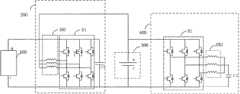
在本申请中,电池振荡加热电路400的结构可以有多种。在一种实施方式中,如图2、图7所示,电池振荡加热电路400包括N相桥臂B2;储能单元包括N个线圈KM2和第二电容C2,N个线圈KM2的第一端一一对应连接至N相桥臂B2的中点,N个线圈KM2的第二端共接并连接至电池300的正极,第二电容C2的第一端与N相桥臂B2的第一汇流端连接,第二电容C2的第二端、N相桥臂B2的第二汇流端均电池300的负极连接;其中,N≥1。In the present application, the structure of the battery oscillating
虽然图2、图7是以N=3为例进行图示的,但是本领域技术人员应当理解的是,图2、图7的桥臂数量和线圈数量仅是示例。Although FIG. 2 and FIG. 7 are illustrated with N=3 as an example, those skilled in the art should understand that the number of bridge arms and the number of coils in FIG. 2 and FIG. 7 are only examples.
控制器500被配置为在第一预设状态下,控制电池振荡加热电路400中的储能单元(包括N个线圈KM2和第二电容C2)与电池300进行充电和放电,以实现对电池300的加热,以及控制M相桥臂B1使电池300接收来自能量交换接口100的能量从而对电池300进行充电。在第一预设状态下,利用图2所示的降压充电电路200对电池300进行充电的过程已经结合图3和至图6进行了详细描述。接下来描述在第一预设状态下利用图2中的N相桥臂B2、N个线圈KM2、第二电容C2对电池300进行加热的过程。具体地,利用线圈KM2、第二电容C2作为限流缓冲装置,控制N相桥臂B2的导通方式,同时调节导通的桥臂的占空比来控制电池回路相电流,使电池内阻发热从而带动电池温度升高,实现电池300的可控升温。The controller 500 is configured to control the energy storage unit (including the N coils KM2 and the second capacitor C2 ) in the battery oscillating
在一种实施例中,N个线圈KM2为电机绕组(例如驱动电机的电机绕组),N相桥臂B2为桥臂变换器。也即,车辆上的现有电机绕组和桥臂变换器被复用了,使得能够根据需要而实现不同的功能,例如:在电池需要自加热时,N个线圈KM2和N相桥臂B2能够被应用于本申请中描述的各种自加热流程中;在需要驱动车辆时,N个线圈KM2和N相桥臂B2能够被切换成通过控制桥臂B2使与电机绕组对应的电机输出功率,进而驱动车辆。这样,就能够通过复用车辆电机绕组和桥臂变换器,来根据需要实现不同的功能,而且还节省了车辆成本。In one embodiment, the N coils KM2 are motor windings (eg, motor windings for driving a motor), and the N-phase bridge arm B2 is a bridge arm converter. That is, the existing motor windings and bridge arm converters on the vehicle are reused, so that different functions can be realized according to needs, for example: when the battery needs self-heating, the N coils KM2 and the N-phase bridge arm B2 can be It is applied to various self-heating processes described in this application; when the vehicle needs to be driven, the N coils KM2 and the N-phase bridge arm B2 can be switched to control the bridge arm B2 to make the motor output power corresponding to the motor winding, to drive the vehicle. In this way, different functions can be realized as required by reusing the vehicle motor winding and the bridge arm converter, and the vehicle cost is also saved.
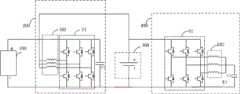
具体来说,可以通过图8中所示的电路拓扑结构来实现电机绕组和桥臂变换器不同的功能。如图8所示,电池能量处理装置还包括:第二开关K2,第二开关K2的第一端与电池300的正极连接,第二开关K2的第二端与第二电容C2的第一端连接;第三开关K3,第三开关K3的第一端与电池300的正极连接,第三开关K3的第二端与N个线圈KM2的第二端连接;控制器500,被配置为在第一预设状态下,控制第二开关K2断开、第三开关K3闭合,并控制电池振荡加热电路400中的储能单元与电池300进行充电和放电,以实现对电池300的加热,以及控制M相桥臂B1使电池300接收来自能量交换接口100的能量,以实现对电池300的充电;控制器500,还被配置为在第三预设状态下,控制降压充电电路200处于不接收来自能量交换接口100的能量的状态时,控制第二开关K2闭合、第三开关K3断开,并控制桥臂变换器使与电机绕组对应的电机输出功率。其中,第三预设状态指的是电机驱动状态。Specifically, the different functions of the motor winding and the bridge arm converter can be realized through the circuit topology shown in FIG. 8 . As shown in FIG. 8 , the battery energy processing device further includes: a second switch K2, the first end of the second switch K2 is connected to the positive electrode of the battery 300, and the second end of the second switch K2 is connected to the first end of the second capacitor C2 connection; the third switch K3, the first end of the third switch K3 is connected to the positive pole of the battery 300, and the second end of the third switch K3 is connected to the second ends of the N coils KM2; the controller 500 is configured to In a preset state, the second switch K2 is controlled to be turned off and the third switch K3 is turned on, and the energy storage unit in the battery oscillating heating circuit 400 is controlled to charge and discharge the battery 300, so as to realize the heating of the battery 300 and control the The M-phase bridge arm B1 enables the battery 300 to receive energy from the energy exchange interface 100, so as to charge the battery 300; the controller 500 is further configured to control the step-down charging circuit 200 to not receive energy in the third preset state When the energy from the energy exchange interface 100 is in the state, the second switch K2 is controlled to be closed, the third switch K3 is opened, and the bridge arm converter is controlled to make the motor output power corresponding to the motor winding. Wherein, the third preset state refers to the motor drive state.
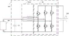
在另一种实施方式中,如图9所示,电池振荡加热电路400包括N相桥臂B2,N相桥臂B2的第一汇流端连接电池300的正极,N相桥臂B2的第二汇流端连接电池300的负极;储能单元包括N个线圈KM2和第三电容C3,N个线圈KM2的第一端一一对应连接至N相桥臂B2的中点,N个线圈KM2的第二端共接,第三电容C3的第一端与N个线圈B2的第二端连接,第三电容C3的第二端与N相桥臂B2的第二汇流端连接;其中,N≥1。In another embodiment, as shown in FIG. 9 , the battery oscillating
虽然图9是以N=3为例进行图示的,但是本领域技术人员应当理解的是,图9的桥臂数量和线圈数量仅是示例。Although FIG. 9 is illustrated with N=3 as an example, those skilled in the art should understand that the number of bridge arms and the number of coils in FIG. 9 are only examples.
控制器500,被配置为在第一预设状态下控制电池振荡加热电路400中的储能单元(包括第三电容C3)与电池300进行充电和放电,以实现对电池300的加热,以及控制M相桥臂B1使电池300接收来自能量交换接口100的能量,以实现对电池300的充电。The controller 500 is configured to control the energy storage unit (including the third capacitor C3 ) in the battery oscillating
在第一预设状态下,利用图9所示的降压充电电路200对电池300进行充电的过程已经结合图3至图6进行了详细描述。接下来描述在第一预设状态下利用图9中的N相桥臂B2、N个线圈KM2以及第三电容C3对电池300进行加热的过程。In the first preset state, the process of using the step-down
首先,在第一过程中,控制器500可以控制N相桥臂B2的所有下桥臂断开,并控制N相桥臂B2的至少一个上桥臂导通,此时,电流从电池300的正极流出,流经导通的上桥臂、与导通的上桥臂连接的线圈和第三电容C3,最后回到电池300的负极。在该过程中,电池300为向外放电状态,第三电容C3接收与导通的上桥臂连接的线圈的能量,电压不断增大,实现储能。First, in the first process, the controller 500 may control all the lower arms of the N-phase bridge arm B2 to be turned off, and control at least one upper arm of the N-phase bridge arm B2 to be turned on. At this time, the current flows from the
接下来,在第二过程中,控制器500可以控制N相桥臂B2的所有上桥臂断开,并控制N相桥臂B2的下桥臂中、与存在续流电流的线圈连接的下桥臂导通,此时,电流从存在续流电流的线圈流出,流经第三电容C3和导通的下桥臂,最后回到存在续流电流的线圈。在该过程中,由于线圈的续流作用,第三电容C3继续接收线圈的能量,电压不断增大。Next, in the second process, the controller 500 may control all the upper arms of the N-phase bridge arm B2 to be disconnected, and control the lower arm of the N-phase bridge arm B2 that is connected to the coil with freewheeling current. The bridge arm is turned on. At this time, the current flows out from the coil with freewheeling current, flows through the third capacitor C3 and the lower bridge arm that is turned on, and finally returns to the coil with freewheeling current. During this process, due to the freewheeling action of the coil, the third capacitor C3 continues to receive the energy of the coil, and the voltage increases continuously.
在第三过程中,随着第三电容C3两端的电压不断增大,第三电容C3会自动从接收线圈KM2的能量变换为向线圈KM2释放能量,此时,电流从第三电容C3流出,流经与导通的下桥臂连接的线圈、导通的下桥臂,最后回到第三电容C3。在该过程中,第三电容C3两端的电压不断减小。In the third process, as the voltage across the third capacitor C3 continues to increase, the third capacitor C3 will automatically transform from the energy of the receiving coil KM2 to releasing energy to the coil KM2. At this time, the current flows from the third capacitor C3, It flows through the coil connected to the conductive lower bridge arm, the conductive lower bridge arm, and finally returns to the third capacitor C3. During this process, the voltage across the third capacitor C3 decreases continuously.
之后,在第四过程中,控制器500可以控制N相桥臂B2的所有下桥臂断开,控制N相桥臂B2的至少一个上桥臂导通,此时,电流从第三电容C3流出,流经与导通的上桥臂连接的线圈、导通的上桥臂、电池300的正极和电池300的负极,最后回到第三电容C3。在该过程中,电池300为充电状态。After that, in the fourth process, the controller 500 may control all the lower arms of the N-phase bridge arm B2 to turn off, and control at least one upper bridge arm of the N-phase bridge arm B2 to be turned on. At this time, the current flows from the third capacitor C3 The flow out, flows through the coil connected to the conductive upper bridge arm, the conductive upper bridge arm, the positive electrode of the
随着第三电容C3两端的电压不断降低,第三电容C3和与导通的上桥臂连接的线圈由向电池释放能量切换到接收电池的能量,此时,电流流向又回到第一过程中所述的流向,电池300开始向外放电。As the voltage across the third capacitor C3 continues to decrease, the third capacitor C3 and the coil connected to the connected upper bridge arm switch from releasing energy to the battery to receiving energy from the battery. At this time, the current flow returns to the first process In the flow direction described in , the
上述四个过程不断循环,使第三电容C3与电池300之间能够快速进行循环式充/放电。由于电池内阻的存在,产生大量的热使得电池快速升温,提高电池加热效率。The above-mentioned four processes are continuously cycled, so that the cyclic charge/discharge can be rapidly performed between the third capacitor C3 and the
在一种实施例中,N个线圈KM2为电机绕组(例如驱动电机的电机绕组),N相桥臂B2为桥臂变换器。也即,车辆上的现有电机绕组和桥臂变换器被复用了,使得能够根据需要而实现不同的功能。具体来说,可以通过图10中所示的电路拓扑结构来实现电机绕组和桥臂变换器不同的功能。如图10所示,电池能量处理装置还包括:第四开关K4,其中,第四开关K4的第一端与N个线圈KM2的第二端连接,第四开关K4的第二端与第三电容C3的第一端连接;控制器500,被配置为在第一预设状态下,控制第四开关K4闭合,并控制电池振荡加热电路400中的储能单元与电池300进行充电和放电,以实现对电池300的加热,以及控制M相桥臂B1使电池300接收来自能量交换接口100的能量,以实现对电池300的充电;控制器500,还被配置为在第三预设状态下,控制降压充电电路200处于不接收来自能量交换接口100的能量的状态,控制第四开关K4断开,并控制桥臂变换器使与电机绕组对应的电机输出功率。In one embodiment, the N coils KM2 are motor windings (eg, motor windings for driving a motor), and the N-phase bridge arm B2 is a bridge arm converter. That is, the existing motor windings and bridge arm inverters on the vehicle are multiplexed so that different functions can be implemented as needed. Specifically, the different functions of the motor winding and the bridge arm converter can be implemented through the circuit topology shown in FIG. 10 . As shown in FIG. 10 , the battery energy processing device further includes: a fourth switch K4, wherein the first end of the fourth switch K4 is connected to the second ends of the N coils KM2, and the second end of the fourth switch K4 is connected to the third The first end of the capacitor C3 is connected; the controller 500 is configured to control the fourth switch K4 to close in the first preset state, and control the energy storage unit in the battery
另外,上述第四开关K4除了可以设置在N个线圈KM2的第二端与第三电容C3的第一端之间外,也可以设置在N相桥臂B2的第一汇流端与第三电容C3的第一端之间(如图11中所示)。In addition, the above-mentioned fourth switch K4 can be disposed between the second end of the N coils KM2 and the first end of the third capacitor C3, and can also be disposed between the first bus end of the N-phase bridge arm B2 and the third capacitor between the first ends of C3 (as shown in Figure 11).
图12是根据一示例性实施例示出的另一种电池能量处理装置的电路拓扑图。如图12所示,电池能量处理装置还包括第五开关K5,第五开关K5的第一端与能量交换接口100的正极连接,第五开关K5的第二端与第三电容C3的第一端连接;控制器500,还被配置为在第四预设状态,控制降压充电电路200处于不接收来自能量交换接口100的能量的状态,并控制第四开关K4和第五开关K5闭合,以及控制N相桥臂B2使电池300接收来自能量交换接口100的能量,其中,能量交换接口100的能量通过N相桥臂B2、N个线圈KM2和第三电容C3升压后被电池300接收。这样,就能够在电池不需要自加热的情况下利用快速升压充电的方式对电池300进行充电。FIG. 12 is a circuit topology diagram of another battery energy processing device according to an exemplary embodiment. As shown in FIG. 12 , the battery energy processing device further includes a fifth switch K5, the first end of the fifth switch K5 is connected to the positive pole of the
在本申请中,第四预设状态指的是在电池300没有自加热需求的情况下利用快速升压充电方式对电池进行充电的状态。In this application, the fourth preset state refers to a state in which the
另外,通过图12所示的电路拓扑可以看出,电池振荡加热电路400被复用于对电池300进行加热和对电池300进行快速升压充电,这两种操作通过第五开关K5进行切换。也即,在第四开关K4闭合、第五开关K5断开的情况下,电池振荡加热电路400可以用于实现电池300的加热,在第四开关K4、第五开关K5均闭合的情况下,电池振荡加热电路400可以用于实现电池300的快速升压充电。In addition, it can be seen from the circuit topology shown in FIG. 12 that the battery oscillating
另外,可以理解的是,本申请中的电池能量处理装置因为增加了第五开关K5,使得本申请具有三种充电方式,第一种充电方式是通过降压充电电路200进行降压充电,第二种充电方式是通过第四开关K4、第五开关K5、N相桥臂B2、N个线圈KM2、第三电容C3进行升压充电,第三种充电方式为对电池进行直接充电,而且这三种充电方式不并行执行。在储能单元与电池300进行充电和放电以对电池300进行自加热期间,需要闭合第四开关K4、断开第五开关K5,避免在自加热期间升压充电方式、直接充电的方式起作用,而且如果在自加热期间电池300有充电需求的话,需要通过降压充电电路200进行降压充电。在储能单元与电池300不进行充电和放电以对电池300进行加热的情况下,如果电池300有充电需求的话,由于此时电池300的两端没有因自加热导致的电压波动,所以此时可以断开降压充电电路200、导通第四开关K4和第五开关K5,以通过N相桥臂B2、N个线圈KM2、第三电容C3对电池300进行快速升压充电,或者也可以断开第四开关K4、第五开关K5,以通过降压充电电路200对电池300进行降压充电,或者还可以闭合第四开关K4和第五开关K5,以通过直接充电方式进行充电。In addition, it can be understood that, because the fifth switch K5 is added to the battery energy processing device in the present application, the present application has three charging modes. The first charging mode is to perform step-down charging through the step-down
另外,如果需要利用储能单元与电池300的充放电对电池300进行自加热,则说明电池300目前处于低温状态,所以在本申请中,利用降压充电电路200对电池300进行降压充电的电流应当小于电池低温状态下充电时会对电池造成损伤的电流,这也意味着,利用降压充电电路200进行降压充电的电流不能太高。所以,在不需要利用N相桥臂B2、N个线圈KM2和第三电容C3对电池进行加热的情况下,如果电池300需要进行升压充电,则优选使用N相桥臂B2、N个线圈KM2、第三电容C3、第四开关K4和第五开关K5对电池300进行快速升压充电,其中, N相桥臂B2、N个线圈KM2、第三电容C3、第四开关K4和第五开关K5组成的快速升压充电电路被配置为能够利用大电流对电池进行快速升压充电。In addition, if the
在本申请另一实施例中,图12的拓扑结构还可以实现在电池不需要自加热的情况下利用直接充电的方式对电池300进行充电。具体为:控制器500还被配置为在第五预设状态下,控制第四开关K4和第五开关K5导通,并控制N相桥臂B2的下桥臂关断,N相桥臂B2的上桥臂闭合或者上桥臂断开,此时,来自能量交换接口100的能量经过N个线圈KM2和N相桥臂B2的上桥臂后,流至电池300的正极对电池进行充电,即使电池300直接接收来自能量交换接口100的能量。In another embodiment of the present application, the topology of FIG. 12 can also be used to charge the
如本领域普通技术人员所知晓的,1、N相桥臂B2的上桥臂和下桥臂不能同时导通;2、其中一个导通,另一个就是关断的,如上桥臂导通则下桥臂关断,上桥臂关断则下桥臂导通;3、其中一个关断,另一个可以是关断的也可以是导通的,如上桥臂关断则下桥臂关断或导通,上桥臂关断则上桥臂关断或导通。As known to those of ordinary skill in the art, 1. The upper bridge arm and the lower bridge arm of the N-phase bridge arm B2 cannot be turned on at the same time; 2. One of them is turned on, and the other is turned off. If the upper bridge arm is turned on, then The lower arm is turned off, and the upper arm is turned off, the lower arm is turned on; 3. One of them is turned off, and the other can be turned off or turned on. If the upper arm is turned off, the lower arm is turned off. If the upper bridge arm is turned off, the upper bridge arm is turned off or turned on.
下面结合图13至图16描述在第四开关K4、第五开关K5导通的情况下利用电池振荡加热电路400对电池300进行升压充电的过程,其中,在升压充电过程中,第一开关K1处于断开状态。The following describes the process of boosting and charging the
在图13中,控制器500控制N相桥臂B2的所有下桥臂断开,控制N相桥臂B2的至少一个上桥臂导通,则,电流从电池300的正极流出,依次流过N相桥臂B2的导通的上桥臂、N个线圈KM2中与导通的上桥臂相连接的线圈、第三电容C3后回到电池300的负极。这样,就能够实现电池300向第三电容C3充电。另外,通过控制上桥臂的导通数量以及导通占空比,能够控制充电电流的大小,进而控制充电功率的大小。In FIG. 13 , the controller 500 controls all the lower arms of the N-phase bridge arm B2 to be turned off, and controls at least one upper bridge arm of the N-phase bridge arm B2 to be turned on, then the current flows out from the positive electrode of the
在一个示例中,假设N相桥臂B2包括3个桥臂a1、a2和a3,线圈KM2包括3个线圈L1、L2和L3,其中,线圈L1的一端与桥臂a1的中点连接,线圈L2的一端与桥臂a2的中点连接,线圈L3与桥臂a3的中点连接。然后,控制器500控制桥臂a1、a2和a3的所有下桥臂断开,控制桥臂a1和a2的上桥臂导通并控制器桥臂a3的上桥臂断开,则电池300的正极、桥臂a1的上桥臂、线圈L1、第三电容C3和电池300的负极构成一个给第三电容C3充电的电流循环回路,电池300的正极、桥臂a2的上桥臂、线圈L2、第三电容C3和电池300的负极构成一个给第三电容C3充电的电流循环回路。In an example, it is assumed that the N-phase bridge arm B2 includes three bridge arms a1, a2 and a3, and the coil KM2 includes three coils L1, L2 and L3, wherein one end of the coil L1 is connected to the midpoint of the bridge arm a1, and the coil One end of L2 is connected to the midpoint of the bridge arm a2, and the coil L3 is connected to the midpoint of the bridge arm a3. Then, the controller 500 controls all the lower arms of the bridge arms a1, a2 and a3 to be turned off, controls the upper arms of the bridge arms a1 and a2 to be turned on and the upper arm of the controller arm a3 is turned off, then the
然后,在图14中,控制器500控制N相桥臂B2的所有上桥臂断开,控制N相桥臂B2的下桥臂中、与存在续流电流的线圈相连接的下桥臂导通,则,续流电流就在由导通的下桥臂、与导通的下桥臂相连接的线圈和第三电容构成的回路中流动。这样,就能够将存在续流电流的线圈中的能量转移给第三电容C3。Then, in FIG. 14 , the controller 500 controls all the upper arms of the N-phase bridge arm B2 to be disconnected, and controls the conduction of the lower arm of the lower arm of the N-phase bridge arm B2 that is connected to the coil with freewheeling current. On, the freewheeling current flows in the loop formed by the conductive lower bridge arm, the coil connected with the conductive lower bridge arm and the third capacitor. In this way, the energy in the coil in which the freewheeling current exists can be transferred to the third capacitor C3.
仍然以上面的示例为例。由于在上面的示例中是控制桥臂a1和a2的上桥臂导通,所以现在应当控制N相桥臂B2的所有上桥臂断开,控制N相桥臂B2的a1和a2的下桥臂导通以及a3的下桥臂断开,则桥臂a1的下桥臂、线圈L1、第三电容C3构成一个将线圈L1中的能量转移给第三电容C3的续流循环回路,桥臂a2的下桥臂、线圈L2、第三电容C3构成一个将线圈L2中的能量转移给第三电容C3的续流循环回路。Still taking the example above. Since the upper arms of the control arms a1 and a2 are turned on in the above example, all upper arms of the N-phase arm B2 should be controlled to be turned off, and the lower arms of a1 and a2 of the N-phase arm B2 should be controlled to be turned off. When the arm is turned on and the lower arm of a3 is disconnected, the lower arm of the bridge arm a1, the coil L1 and the third capacitor C3 form a freewheeling loop that transfers the energy in the coil L1 to the third capacitor C3. The lower arm of a2, the coil L2, and the third capacitor C3 form a freewheeling loop that transfers the energy in the coil L2 to the third capacitor C3.
接下来,在图15中,控制器500控制N相桥臂B2的所有上桥臂断开,控制N相桥臂B2的至少一个下桥臂导通,则电流从能量交换接口100的正极,依次流过与导通的下桥臂连接的线圈和导通的下桥臂,最后回到能量交换接口100的负极。这样,就能够实现诸如充电桩之类的外部供电设备向线圈充电。另外,通过控制下桥臂的导通数量以及导通占空比,能够控制充电电流的大小,进而控制充电功率的大小。Next, in FIG. 15 , the controller 500 controls all the upper arms of the N-phase bridge arm B2 to be turned off, and controls at least one lower arm of the N-phase bridge arm B2 to be turned on, so that the current flows from the positive pole of the
之后,在图16中,控制器500控制N相桥臂B2的、与存在续流电流的线圈连接的上桥臂导通,并控制N相桥臂B2的所有下桥臂断开,则,电流依次流经能量交换接口100的正极、与导通的上桥臂连接的线圈、导通的上桥臂、电池300的正极、电池300的负极,最后回到能量交换接口100的负极。这样,就能够由诸如充电桩之类的外部供电设备以及线圈KM2共同向电池300充电。After that, in FIG. 16 , the controller 500 controls the upper bridge arm of the N-phase bridge arm B2 connected to the coil with freewheeling current to be turned on, and controls all the lower bridge arms of the N-phase bridge arm B2 to turn off, then, The current flows sequentially through the positive pole of the
因此,控制器500通过控制N相桥臂B2的上下桥臂交替导通,使得图13至图16的状态交替工作,实现对电池300的升压充电。Therefore, the controller 500 controls the upper and lower bridge arms of the N-phase bridge arm B2 to be turned on alternately, so that the states of FIG. 13 to FIG. 16 work alternately, so as to realize the boost charging of the
在又一种实施方式中,如图17所示,电池振荡加热电路400包括N相桥臂B2,N相桥臂B2的第一汇流端连接电池300的正极,N相桥臂B2的第二汇流端连接电池300的负极;储能单元包括N个线圈KM2,N个线圈KM2的第一端一一对应连接至N相桥臂B2的中点,N个线圈KM2的第二端共接;其中,N≥2。In yet another embodiment, as shown in FIG. 17 , the battery oscillating
虽然图17是以N=3为例进行图示的,但是本领域技术人员应当理解的是,图17的桥臂数量和线圈数量仅是示例。Although FIG. 17 is illustrated with N=3 as an example, those skilled in the art should understand that the number of bridge arms and the number of coils in FIG. 17 are only examples.
控制器500被配置为在第一预设状态下,控制电池振荡加热电路400中的储能单元(包括N个线圈KM2)与电池300进行充电和放电,以实现对电池300的加热,以及控制M相桥臂B1使电池300接收来自能量交换接口100的能量从而对电池300进行充电。在第一预设状态下,利用图17所示的降压充电电路200对电池300进行充电的过程已经结合图3至图6进行了详细描述。接下来描述在第一预设状态下利用图17中的N相桥臂B2、N个线圈KM2对电池300进行加热的过程。具体地,利用线圈KM2作为限流缓冲装置,控制N相桥臂B2的导通方式,同时调节导通的桥臂的占空比来控制电池回路相电流,使电池内阻发热从而带动电池温度升高,实现电池300的可控升温。The controller 500 is configured to control the energy storage unit (including the N coils KM2 ) in the battery oscillating
图18是根据一示例性实施例示出的另一种电池能量处理装置的电路拓扑图。如图18所示,上述电池能量处理装置还包括第六开关K6,其中,第六开关K6的第一端与M个线圈KM1的第二端连接,第六开关K6的第二端与电池300的正极连接。FIG. 18 is a circuit topology diagram of another battery energy processing device according to an exemplary embodiment. As shown in FIG. 18 , the above-mentioned battery energy processing device further includes a sixth switch K6, wherein the first end of the sixth switch K6 is connected to the second ends of the M coils KM1, and the second end of the sixth switch K6 is connected to the
通过控制第六开关K6的通断,能够将降压充电电路200应用于除了给电池300进行降压充电之外的功能中,例如,用作驱动电路。也即控制器500被配置为在第一预设状态下,控制第六开关K6闭合,并控制电池振荡加热电路400中的储能单元与电池300进行充电和放电,以实现对电池300的加热,以及控制M相桥臂B1使电池300接收来自能量交换接口100的能量,以实现对电池300的充电;控制器500还被配置为在第六预设状态,控制第六开关K6闭合,并控制降压充电电路200处于不接收来自能量交换接口100的能量的状态,以及控制桥臂变换器使与电机绕组对应的电机输出功率。其中,第六预设状态指的是电机驱动状态。By controlling the on-off of the sixth switch K6, the step-down
因此,通过增加第六开关K6,可以实现降压充电电路200的第二功能,且不会影响本申请的电池能量处理装置的其他功能,例如电池自加热、电池自加热电路的升压充电功能、电池直接充电、电池驱动等。Therefore, by adding the sixth switch K6, the second function of the step-down
例如,在一种实施例中,M个线圈KM1可以为驱动电机的电机绕组,M相桥臂B1为桥臂变换器,则控制器500可以被配置为在第六预设状态,控制第六开关K6闭合,并控制降压充电电路200处于不接收来自能量交换接口100的能量的状态,以及控制桥臂变换器使与电机绕组对应的电机输出功率,这样就实现了电机驱动功能。其中,第六预设状态指的是电机驱动状态。通过电机绕组、桥臂变换器的复用,能节省车辆成本。For example, in one embodiment, the M coils KM1 may be motor windings of a driving motor, and the M-phase bridge arm B1 may be a bridge arm converter, and the controller 500 may be configured to control the sixth The switch K6 is closed, and the step-down
再例如,在又一种实施例中,M个线圈KM1为压缩机的电机绕组,M相桥臂B1为桥臂变换器,控制器500可以被配置为在第六预设状态,控制第六开关K6闭合,并控制降压充电电路200处于不接收来自能量交换接口100的能量的状态,以及控制桥臂变换器使与电机绕组对应的电机输出功率,这样,就可以利用M个线圈KM1和M相桥臂B1实现压缩机的常用功能,例如制冷功能。通过电机绕组、桥臂变换器的复用,能节省车辆成本。另外,由于压缩机的驱动电流不大,所以非常适用于将压缩机的电机绕组和桥臂变换器复用到降压充电电路200中,以便能够在电池自加热期间进行充电的情况下采用小电流对电池进行如上所述的降压充电。For another example, in another embodiment, the M coils KM1 are motor windings of the compressor, the M-phase bridge arm B1 is the bridge arm converter, and the controller 500 may be configured to control the sixth The switch K6 is closed, and the step-down
另外,在M个线圈KM1和M相桥臂B1被用于车辆驱动功能的情况下,在有需求时,如上描述的快速升压充电、直接充电、电池加热、电机驱动等也是可以执行的。在N个线圈KM2和N相桥臂B2被用于车辆驱动功能的情况下,在有需求时,如上描述的直接充电、利用降压充电电路200的降压充电、压缩机功能等也是可以执行的。In addition, in the case where the M coils KM1 and the M-phase arm B1 are used for the vehicle driving function, the above-described rapid boost charging, direct charging, battery heating, motor driving, etc. can also be performed when required. In the case where the N coils KM2 and the N-phase bridge arm B2 are used for the vehicle driving function, the direct charging as described above, the step-down charging using the step-down
图19是根据一示例性实施例示出的另一种电池能量处理装置的电路拓扑图。如图19所示,上述电池能量处理装置还包括第七开关K7和第八开关K8,第七开关K7的第一端与能量交换接口100的正极连接,第七开关K7的第二端连接至M相桥臂B1的第一汇流端,第八开关K8的第一端与能量交换接口100的负极连接,第八开关K8的第二端连接至M相桥臂B1的第二汇流端;控制器500,还被配置为在第一预设状态和第二预设状态下,均控制第七开关K7、第八开关K8闭合。这样,就能够在充电结束后,可以将降压充电电路200与能量交换接口100完全隔离,避免降压充电电路200的高压串入能量交换接口100的同时,有人员接触能量交换接口100,引发人身安全。FIG. 19 is a circuit topology diagram of another battery energy processing device according to an exemplary embodiment. As shown in FIG. 19 , the above-mentioned battery energy processing device further includes a seventh switch K7 and an eighth switch K8, the first end of the seventh switch K7 is connected to the positive pole of the
图20是根据一示例性实施例示出的一种电池能量处理方法的流程图。如图20所示,方法包括:Fig. 20 is a flow chart of a battery energy processing method according to an exemplary embodiment. As shown in Figure 20, the method includes:
在S131中,在第一预设状态下,控制电池振荡加热电路与电池进行充电和放电,以实现对电池的加热。In S131, in the first preset state, the battery oscillating heating circuit is controlled to charge and discharge the battery, so as to realize the heating of the battery.
在S132中,控制降压充电电路接收来自能量交换接口的能量输出至电池,以实现对电池的充电。In S132, the step-down charging circuit is controlled to receive the energy output from the energy exchange interface to the battery, so as to realize the charging of the battery.
其中,所述降压充电电路,包括:M相桥臂,所述M相桥臂的第一汇流端连接所述能量交换接口的正极,所述M相桥臂的第二汇流端、所述电池的负极分别与所述能量交换接口的负极连接,其中,M≥1;M个线圈,所述M个线圈的第一端一一对应连接至所述M相桥臂的中点,所述M个线圈的第二端连接所述电池的正极;第一电容,所述第一电容的第一端与所述M相桥臂的第一汇流端连接,所述第一电容的第二端与所述M相桥臂的所述第二汇流端连接;所述电池振荡加热电路与所述电池连接。The step-down charging circuit includes: an M-phase bridge arm, the first bus terminal of the M-phase bridge arm is connected to the positive pole of the energy exchange interface, the second bus terminal of the M-phase bridge arm, the The negative poles of the battery are respectively connected with the negative poles of the energy exchange interface, wherein M≥1; M coils, the first ends of the M coils are connected to the midpoint of the M-phase bridge arms in a one-to-one correspondence, and the The second ends of the M coils are connected to the positive electrode of the battery; the first capacitor, the first end of the first capacitor is connected to the first bus end of the M-phase bridge arm, and the second end of the first capacitor connected with the second bus terminal of the M-phase bridge arm; the battery oscillating heating circuit is connected with the battery.
另外,本申请对S131和S132的先后顺序不做限定。也即,例如,如果检测到电池需要自加热和充电,那么可以先启动S131后启动S142,也可以先启动S142后启动S141,还可以同时启动S141和S142。当然,如果是在执行电池充电期间检测到电池需要自加热,那么可以直接启动S131对电池进行加热;如果是在执行电池自加热期间检测到电池需要充电,那么也可以直接启动S132以对电池进行充电。In addition, the present application does not limit the sequence of S131 and S132. That is, for example, if it is detected that the battery needs self-heating and charging, S131 can be started first and then S142 can be started, or S142 can be started first and then S141 can be started, or S141 and S142 can be started at the same time. Of course, if it is detected that the battery needs self-heating during battery charging, then S131 can be directly started to heat the battery; if it is detected that the battery needs to be charged during battery self-heating, then S132 can also be directly started to heat the battery. Charge.
通过上述技术方案,能够在控制电池振荡加热电路与电池进行充电和放电以实现对电池进行加热期间,控制降压充电电路接收来自能量交换接口的能量以实现对电池的充电,这样就能够在电池自加热的时候实现电池的充电。Through the above technical solution, during the period when the battery oscillating heating circuit is controlled to charge and discharge the battery to realize the heating of the battery, the step-down charging circuit can be controlled to receive the energy from the energy exchange interface to realize the charging of the battery. The battery is charged when it is self-heating.
在具体实施例中,在第一预设状态下,控制器500控制所述电池振荡加热电路400中的储能单元与电池300进行充电和放电以实现对电池的加热。上述使储能单元与电池300进行充电和放电是指电池300向储能单元提供能量,使电池300放电,以及储能单元向电池300提供能量,使电池充电。In a specific embodiment, in the first preset state, the controller 500 controls the energy storage unit in the battery oscillating
可选地,所述方法还包括:Optionally, the method further includes:
在第二预设状态下,控制所述电池振荡加热电路中的储能单元处于不与所述电池进行充电和放电的状态且所述降压充电电路处于不接收来自所述能量交换接口的能量的状态,并控制设置于所述能量交换接口的正极于所述电池的正极之间的第一开关闭合,以使所述电池直接接收来自所述能量交换接口的能量。In a second preset state, the energy storage unit in the battery oscillating heating circuit is controlled to be in a state of not charging and discharging with the battery and the step-down charging circuit is not receiving energy from the energy exchange interface state, and control the first switch disposed between the positive pole of the energy exchange interface and the positive pole of the battery to be closed, so that the battery directly receives the energy from the energy exchange interface.
可选地,所述电池振荡加热电路包括N相桥臂;所述储能单元包括N个线圈和第二电容,所述N个线圈的第一端一一对应连接至所述N相桥臂的中点,所述N个线圈的第二端共接并连接至电池的正极,所述第二电容的第一端与所述N相桥臂的第一汇流端连接,所述第二电容的第二端、所述N相桥臂的第二汇流端均与所述电池的负极连接;其N≥1;所述N个线圈为电机绕组,所述N相桥臂为桥臂变换器;Optionally, the battery oscillating heating circuit includes an N-phase bridge arm; the energy storage unit includes N coils and a second capacitor, and the first ends of the N coils are connected to the N-phase bridge arm in a one-to-one correspondence. the midpoint of the N coils, the second ends of the N coils are connected in common and connected to the positive pole of the battery, the first end of the second capacitor is connected to the first bus terminal of the N-phase bridge arm, the second capacitor The second end of the N-phase bridge arm and the second confluence end of the N-phase bridge arm are connected to the negative electrode of the battery; N≥1; the N coils are motor windings, and the N-phase bridge arm is a bridge arm converter ;
所述在第一预设状态下,控制电池振荡加热电路中的储能单元与电池进行充电和放电,以实现对所述电池的加热,以及控制降压充电电路接收来自能量交换接口的能量输出至所述电池,以实现对所述电池的充电,包括:In the first preset state, the energy storage unit in the battery oscillating heating circuit is controlled to charge and discharge the battery to achieve heating of the battery, and the step-down charging circuit is controlled to receive the energy output from the energy exchange interface to the battery, so as to realize the charging of the battery, including:
在第一预设状态下,控制设置于所述电池的正极与所述第二电容的第一端之间的第二开关断开、设置于所述电池的正极与所述N个线圈的第二端之间的第三开关闭合,并控制所述电池振荡加热电路中的储能单元与所述电池进行充电和放电,以实现对所述电池的加热,以及控制所述M相桥臂使所述电池接收来自所述能量交换接口的能量,以实现对所述电池的充电;In the first preset state, the second switch disposed between the positive electrode of the battery and the first end of the second capacitor is controlled to be turned off, and the second switch disposed between the positive electrode of the battery and the first end of the N coils is controlled to be disconnected. The third switch between the two ends is closed, and controls the energy storage unit in the battery oscillating heating circuit to charge and discharge the battery, so as to heat the battery, and control the M-phase bridge arm to make the battery receives energy from the energy exchange interface to charge the battery;
所述方法还包括:The method also includes:
在第三预设状态下,控制所述第二开关闭合、所述第三开关断开,并控制所述桥臂变换器使与所述电机绕组对应的电机输出功率。In a third preset state, the second switch is controlled to be turned on, the third switch is turned off, and the bridge arm converter is controlled to make the motor corresponding to the motor winding output power.
可选地,所述电池振荡加热电路包括N相桥臂,所述N相桥臂的第一汇流端连接所述电池的正极,所述N相桥臂的第二汇流端连接所述电池的负极;所述储能单元包括N个线圈和第三电容,所述N个线圈的第一端一一对应连接至所述N相桥臂的中点,所述N个线圈的第二端共接,所述第三电容的第一端与所述N个线圈的第二端连接,所述第三电容的第二端与所述N相桥臂的第二汇流端连接;N≥1;所述N个线圈为电机绕组,所述N相桥臂为桥臂变换器;Optionally, the battery oscillating heating circuit includes an N-phase bridge arm, the first bus terminal of the N-phase bridge arm is connected to the positive electrode of the battery, and the second bus terminal of the N-phase bridge arm is connected to the battery. negative electrode; the energy storage unit includes N coils and a third capacitor, the first ends of the N coils are connected to the midpoint of the N-phase bridge arm in a one-to-one correspondence, and the second ends of the N coils are in common connected, the first end of the third capacitor is connected to the second ends of the N coils, and the second end of the third capacitor is connected to the second bus end of the N-phase bridge arm; N≥1; The N coils are motor windings, and the N-phase bridge arms are bridge arm converters;
所述在第一预设状态下,控制电池振荡加热电路中的储能单元与电池进行充电和放电,以实现对所述电池的加热,以及控制降压充电电路接收来自能量交换接口的能量输出至所述电池,以实现对所述电池的充电,包括:In the first preset state, the energy storage unit in the battery oscillating heating circuit is controlled to charge and discharge the battery to achieve heating of the battery, and the step-down charging circuit is controlled to receive the energy output from the energy exchange interface to the battery, so as to realize the charging of the battery, including:
在第一预设状态下,控制所述设置于所述N个线圈的第二端与所述第三电容之间的第四开关闭合,并控制所述电池振荡加热电路中的储能单元与所述电池进行充电和放电,以实现对所述电池的加热,以及控制所述M相桥臂使所述电池接收来自所述能量交换接口的能量,以实现对所述电池的充电;In the first preset state, control the fourth switch disposed between the second ends of the N coils and the third capacitor to close, and control the energy storage unit in the battery oscillating heating circuit and the The battery is charged and discharged to achieve heating of the battery, and the M-phase bridge arm is controlled so that the battery receives energy from the energy exchange interface to achieve charging of the battery;
所述方法还包括:The method also includes:
在第三预设状态下,控制所述第四开关断开,并控制所述桥臂变换器使与所述电机绕组对应的电机输出功率。In a third preset state, the fourth switch is controlled to be turned off, and the bridge arm converter is controlled to make the motor corresponding to the motor winding output power.
可选地,所述方法还包括:Optionally, the method further includes:
在第四预设状态,控制所述降压充电电路处于不接收来自所述能量交换接口的能量的状态,并控制所述所述第四开关和设置于所述能量交换接口的正极与所述第三电容之间的第五开关闭合,以及控制所述N相桥臂使所述电池接收来自所述能量交换接口的能量,其中,所述能量交换接口的能量通过所述N相桥臂、所述N个线圈和所述第三电容升压后被所述电池接收。In a fourth preset state, the step-down charging circuit is controlled to be in a state of not receiving energy from the energy exchange interface, and the fourth switch and the positive pole disposed on the energy exchange interface are controlled to be connected to the energy exchange interface. The fifth switch between the third capacitors is closed, and the N-phase bridge arm is controlled so that the battery receives energy from the energy exchange interface, wherein the energy of the energy exchange interface passes through the N-phase bridge arm, The N coils and the third capacitor are received by the battery after being boosted.
可选地,在第五预设状态下,控制第四开关K4和第五开关K5导通,并控制N相桥臂B2使电池300直接接收来自能量交换接口100的能量。Optionally, in the fifth preset state, the fourth switch K4 and the fifth switch K5 are controlled to be turned on, and the N-phase bridge arm B2 is controlled so that the
可选地,所述电池振荡加热电路包括N相桥臂,所述N相桥臂的第一汇流端连接所述电池的正极,所述N相桥臂的第二汇流端连接所述电池的负极;所述储能单元包括N个线圈,所述N个线圈的第一端一一对应连接至所述N相桥臂的中点,所述N个线圈的第二端共接,所述N相桥臂的第二汇流端连接至所述电池的负极;其中,N≥2。Optionally, the battery oscillating heating circuit includes an N-phase bridge arm, the first bus terminal of the N-phase bridge arm is connected to the positive electrode of the battery, and the second bus terminal of the N-phase bridge arm is connected to the battery. negative electrode; the energy storage unit includes N coils, the first ends of the N coils are connected to the midpoints of the N-phase bridge arms in a one-to-one correspondence, the second ends of the N coils are connected in common, the The second bus terminal of the N-phase bridge arm is connected to the negative electrode of the battery; wherein, N≧2.
可选地,所述M个线圈为压缩机的电机绕组,所述M相桥臂为压缩机的桥臂变换器;Optionally, the M coils are motor windings of a compressor, and the M-phase bridge arm is a bridge arm converter of the compressor;
所述在第一预设状态下,控制电池振荡加热电路中的储能单元与电池进行充电和放电,以实现对所述电池的加热,以及控制降压充电电路接收来自能量交换接口的能量输出至所述电池,以实现对所述电池的充电,包括:In the first preset state, the energy storage unit in the battery oscillating heating circuit is controlled to charge and discharge the battery to achieve heating of the battery, and the step-down charging circuit is controlled to receive the energy output from the energy exchange interface to the battery, so as to realize the charging of the battery, including:
在第一预设状态下,控制设置于所述M个线圈的第二端和所述电池的正极之间的第六开关闭合,并控制所述电池振荡加热电路中的储能单元与所述电池进行充电和放电,以实现对所述电池的加热,以及控制所述M相桥臂使所述电池接收来自所述能量交换接口的能量,以实现对所述电池的充电;In the first preset state, the sixth switch arranged between the second ends of the M coils and the positive electrode of the battery is controlled to be closed, and the energy storage unit in the battery oscillating heating circuit is controlled to be connected to the battery. charging and discharging the battery to realize the heating of the battery, and controlling the M-phase bridge arm to make the battery receive the energy from the energy exchange interface to realize the charging of the battery;
所述方法还包括:The method also includes:
在第六预设状态,控制所述第六开关闭合,并控制所述降压充电电路处于不接收来自所述能量交换接口的能量的状态,并控制所述第六开关闭合,以及控制所述桥臂变换器使与所述电机绕组对应的电机输出功率。In a sixth preset state, the sixth switch is controlled to be closed, the step-down charging circuit is controlled to be in a state of not receiving energy from the energy exchange interface, the sixth switch is controlled to be closed, and the The bridge arm converter makes the motor output power corresponding to the motor winding.
可选地,所述方法还包括:Optionally, the method further includes:
在所述第一预设状态和所述第二预设状态下,均控制设置于所述能量交换接口的正极与所述M相桥臂的第一汇流端之间的第七开关、设置于所述能量交换接口的负极与所述M相桥臂的第二汇流端之间的第八开关闭合。In both the first preset state and the second preset state, the seventh switch disposed between the positive electrode of the energy exchange interface and the first bus terminal of the M-phase bridge arm is controlled, and the seventh switch disposed in the The eighth switch between the negative pole of the energy exchange interface and the second bus terminal of the M-phase bridge arm is closed.
根据本申请实施例的电池能量处理方法中各个步骤的具体实现方式已经在根据本申请实施例的电池能量处理装置中进行了详细描述,此处不再赘述。The specific implementation of each step in the battery energy processing method according to the embodiment of the present application has been described in detail in the battery energy processing device according to the embodiment of the present application, and details are not repeated here.
根据本申请的又一实施例,提供一种车辆,其包括电池及根据本申请实施例的电池能量处理装置。According to yet another embodiment of the present application, there is provided a vehicle including a battery and a battery energy processing device according to the embodiment of the present application.
以上结合附图详细描述了本申请的优选实施方式,但是,本申请并不限于上述实施方式中的具体细节,在本申请的技术构思范围内,可以对本申请的技术方案进行多种简单变型,这些简单变型均属于本申请的保护范围。The preferred embodiments of the present application have been described in detail above with reference to the accompanying drawings. However, the present application is not limited to the specific details of the above-mentioned embodiments. Within the scope of the technical concept of the present application, various simple modifications can be made to the technical solutions of the present application. These simple modifications all belong to the protection scope of the present application.
另外需要说明的是,在上述具体实施方式中所描述的各个具体技术特征,在不矛盾的情况下,可以通过任何合适的方式进行组合。为了避免不必要的重复,本申请对各种可能的组合方式不再另行说明。In addition, it should be noted that each specific technical feature described in the above-mentioned specific implementation manner may be combined in any suitable manner under the circumstance that there is no contradiction. In order to avoid unnecessary repetition, various possible combinations are not described in this application.
此外,本申请的各种不同的实施方式之间也可以进行任意组合,只要其不违背本申请的思想,其同样应当视为本申请所公开的内容。In addition, the various embodiments of the present application can also be combined arbitrarily, as long as they do not violate the idea of the present application, they should also be regarded as the content disclosed in the present application.
Claims (20)
Priority Applications (1)
| Application Number | Priority Date | Filing Date | Title |
|---|---|---|---|
| CN202010502046.9ACN111404247B (en) | 2020-06-04 | 2020-06-04 | Battery energy processing device, method and vehicle |
Applications Claiming Priority (1)
| Application Number | Priority Date | Filing Date | Title |
|---|---|---|---|
| CN202010502046.9ACN111404247B (en) | 2020-06-04 | 2020-06-04 | Battery energy processing device, method and vehicle |
Publications (2)
| Publication Number | Publication Date |
|---|---|
| CN111404247Atrue CN111404247A (en) | 2020-07-10 |
| CN111404247B CN111404247B (en) | 2020-10-23 |
Family
ID=71413836
Family Applications (1)
| Application Number | Title | Priority Date | Filing Date |
|---|---|---|---|
| CN202010502046.9AActiveCN111404247B (en) | 2020-06-04 | 2020-06-04 | Battery energy processing device, method and vehicle |
Country Status (1)
| Country | Link |
|---|---|
| CN (1) | CN111404247B (en) |
Cited By (10)
| Publication number | Priority date | Publication date | Assignee | Title |
|---|---|---|---|---|
| CN112078433A (en)* | 2020-08-31 | 2020-12-15 | 上海交通大学 | Low temperature preheating device for vehicle power battery and control method thereof |
| CN113972706A (en)* | 2020-07-23 | 2022-01-25 | 比亚迪股份有限公司 | Vehicle, energy conversion device and control method thereof |
| CN113972707A (en)* | 2020-07-23 | 2022-01-25 | 比亚迪股份有限公司 | Vehicle, energy conversion device, and control method therefor |
| WO2022022463A1 (en)* | 2020-07-28 | 2022-02-03 | 比亚迪股份有限公司 | Automobile battery thermal management system, automobile thermal management system, and electric automobile |
| CN114590172A (en)* | 2020-12-04 | 2022-06-07 | 比亚迪股份有限公司 | Battery energy processing device and method and vehicle |
| CN115139854A (en)* | 2021-03-31 | 2022-10-04 | 比亚迪股份有限公司 | Energy conversion device and control method thereof |
| CN117360329A (en)* | 2022-06-30 | 2024-01-09 | 比亚迪股份有限公司 | Battery self-heating device and method and electric vehicle |
| CN118523461A (en)* | 2024-07-22 | 2024-08-20 | 比亚迪股份有限公司 | Charging and discharging circuit and vehicle |
| WO2024255070A1 (en)* | 2023-06-12 | 2024-12-19 | 宁德时代新能源科技股份有限公司 | Charging and discharging circuit and method, and computing device and control apparatus |
| EP4474210A4 (en)* | 2022-03-31 | 2025-07-16 | Byd Co Ltd | BATTERY SELF-HEATING DEVICE AND METHOD AND VEHICLE |
Citations (15)
| Publication number | Priority date | Publication date | Assignee | Title |
|---|---|---|---|---|
| CN103117421A (en)* | 2013-03-07 | 2013-05-22 | 清华大学 | Low-temperature battery charging method |
| CN105186634A (en)* | 2015-10-26 | 2015-12-23 | 维沃移动通信有限公司 | Charging circuit and mobile terminal |
| US20160322828A1 (en)* | 2013-03-14 | 2016-11-03 | Combined Energies LLC | Power system for multiple power sources |
| US20170018817A1 (en)* | 2014-04-02 | 2017-01-19 | Corvus Energy Ltd. | Method, system, and apparatus for inhibiting thermal runaway of a battery cell |
| CN107666028A (en)* | 2017-08-16 | 2018-02-06 | 同济大学 | A kind of lithium ion battery for electric vehicle low temperature exchanges heater |
| CN108448189A (en)* | 2018-05-16 | 2018-08-24 | 济南保特电子设备有限公司 | The accumulator group realization device that low temperature charges |
| CN108511822A (en)* | 2018-05-08 | 2018-09-07 | 北京航空航天大学 | A kind of lithium ion battery low-temperature heating device and electric vehicle |
| CN209119278U (en)* | 2018-08-23 | 2019-07-16 | 苏州德凌迅动力科技有限公司 | A kind of power battery pack low-temperature heat charging system |
| CN110116653A (en)* | 2019-04-19 | 2019-08-13 | 清华大学 | Drive system of electric automobile, driving circuit and batteries of electric automobile heating means |
| CN209844590U (en)* | 2019-05-29 | 2019-12-24 | 石家庄纽伦制动技术有限公司 | Low-temperature oscillation charging control circuit for storage battery pack |
| CN110808434A (en)* | 2019-09-25 | 2020-02-18 | 浙江合众新能源汽车有限公司 | Heating control method and device for power battery during low-temperature charging of automobile |
| CN110803069A (en)* | 2019-10-22 | 2020-02-18 | 上海交通大学 | Battery dual-circuit power supply resonant AC heating system, control method and battery system |
| CN110949157A (en)* | 2019-12-27 | 2020-04-03 | 成都图翎数控科技有限公司 | Charging device, system and method for traction locomotive |
| CN210468040U (en)* | 2019-09-06 | 2020-05-05 | 上海伊控动力系统有限公司 | Self-heating system for vehicle-mounted battery pack of electric vehicle |
| CN111098760A (en)* | 2018-10-26 | 2020-05-05 | 法法汽车(中国)有限公司 | Device and method for heating battery pack of electric vehicle and electric vehicle |
- 2020
- 2020-06-04CNCN202010502046.9Apatent/CN111404247B/enactiveActive
Patent Citations (15)
| Publication number | Priority date | Publication date | Assignee | Title |
|---|---|---|---|---|
| CN103117421A (en)* | 2013-03-07 | 2013-05-22 | 清华大学 | Low-temperature battery charging method |
| US20160322828A1 (en)* | 2013-03-14 | 2016-11-03 | Combined Energies LLC | Power system for multiple power sources |
| US20170018817A1 (en)* | 2014-04-02 | 2017-01-19 | Corvus Energy Ltd. | Method, system, and apparatus for inhibiting thermal runaway of a battery cell |
| CN105186634A (en)* | 2015-10-26 | 2015-12-23 | 维沃移动通信有限公司 | Charging circuit and mobile terminal |
| CN107666028A (en)* | 2017-08-16 | 2018-02-06 | 同济大学 | A kind of lithium ion battery for electric vehicle low temperature exchanges heater |
| CN108511822A (en)* | 2018-05-08 | 2018-09-07 | 北京航空航天大学 | A kind of lithium ion battery low-temperature heating device and electric vehicle |
| CN108448189A (en)* | 2018-05-16 | 2018-08-24 | 济南保特电子设备有限公司 | The accumulator group realization device that low temperature charges |
| CN209119278U (en)* | 2018-08-23 | 2019-07-16 | 苏州德凌迅动力科技有限公司 | A kind of power battery pack low-temperature heat charging system |
| CN111098760A (en)* | 2018-10-26 | 2020-05-05 | 法法汽车(中国)有限公司 | Device and method for heating battery pack of electric vehicle and electric vehicle |
| CN110116653A (en)* | 2019-04-19 | 2019-08-13 | 清华大学 | Drive system of electric automobile, driving circuit and batteries of electric automobile heating means |
| CN209844590U (en)* | 2019-05-29 | 2019-12-24 | 石家庄纽伦制动技术有限公司 | Low-temperature oscillation charging control circuit for storage battery pack |
| CN210468040U (en)* | 2019-09-06 | 2020-05-05 | 上海伊控动力系统有限公司 | Self-heating system for vehicle-mounted battery pack of electric vehicle |
| CN110808434A (en)* | 2019-09-25 | 2020-02-18 | 浙江合众新能源汽车有限公司 | Heating control method and device for power battery during low-temperature charging of automobile |
| CN110803069A (en)* | 2019-10-22 | 2020-02-18 | 上海交通大学 | Battery dual-circuit power supply resonant AC heating system, control method and battery system |
| CN110949157A (en)* | 2019-12-27 | 2020-04-03 | 成都图翎数控科技有限公司 | Charging device, system and method for traction locomotive |
Cited By (12)
| Publication number | Priority date | Publication date | Assignee | Title |
|---|---|---|---|---|
| CN113972706A (en)* | 2020-07-23 | 2022-01-25 | 比亚迪股份有限公司 | Vehicle, energy conversion device and control method thereof |
| CN113972707A (en)* | 2020-07-23 | 2022-01-25 | 比亚迪股份有限公司 | Vehicle, energy conversion device, and control method therefor |
| CN113972706B (en)* | 2020-07-23 | 2025-02-11 | 比亚迪股份有限公司 | Vehicle, energy conversion device and control method thereof |
| CN113972707B (en)* | 2020-07-23 | 2025-02-11 | 比亚迪股份有限公司 | Vehicle, energy conversion device and control method thereof |
| WO2022022463A1 (en)* | 2020-07-28 | 2022-02-03 | 比亚迪股份有限公司 | Automobile battery thermal management system, automobile thermal management system, and electric automobile |
| CN112078433A (en)* | 2020-08-31 | 2020-12-15 | 上海交通大学 | Low temperature preheating device for vehicle power battery and control method thereof |
| CN114590172A (en)* | 2020-12-04 | 2022-06-07 | 比亚迪股份有限公司 | Battery energy processing device and method and vehicle |
| CN115139854A (en)* | 2021-03-31 | 2022-10-04 | 比亚迪股份有限公司 | Energy conversion device and control method thereof |
| EP4474210A4 (en)* | 2022-03-31 | 2025-07-16 | Byd Co Ltd | BATTERY SELF-HEATING DEVICE AND METHOD AND VEHICLE |
| CN117360329A (en)* | 2022-06-30 | 2024-01-09 | 比亚迪股份有限公司 | Battery self-heating device and method and electric vehicle |
| WO2024255070A1 (en)* | 2023-06-12 | 2024-12-19 | 宁德时代新能源科技股份有限公司 | Charging and discharging circuit and method, and computing device and control apparatus |
| CN118523461A (en)* | 2024-07-22 | 2024-08-20 | 比亚迪股份有限公司 | Charging and discharging circuit and vehicle |
Also Published As
| Publication number | Publication date |
|---|---|
| CN111404247B (en) | 2020-10-23 |
Similar Documents
| Publication | Publication Date | Title |
|---|---|---|
| CN111404247B (en) | Battery energy processing device, method and vehicle | |
| CN111391718B (en) | Battery energy processing device, method and vehicle | |
| CN111404246B (en) | Battery energy processing device, method and vehicle | |
| US12132432B2 (en) | Energy conversion device and vehicle | |
| CN111347853A (en) | Motor control circuit, charging and discharging method, heating method and vehicle | |
| CN113752875A (en) | Vehicle battery heating device and method, vehicle | |
| CN111391717B (en) | Energy conversion device, method and vehicle | |
| EP4516579A1 (en) | Battery heating system and electric vehicle | |
| CN111404245B (en) | Energy conversion device and safety control method thereof | |
| CN116923119A (en) | Dual-motor driving system, control method and vehicle | |
| US20250046906A1 (en) | Battery self-heating device and method, and vehicle | |
| CN117044099A (en) | Battery heating topology circuit and power utilization device | |
| CN117656947B (en) | Battery self-heating system and vehicle | |
| CN113752865B (en) | Energy conversion method and device and vehicle | |
| CN118849882A (en) | Battery control system and vehicle | |
| CN117855682A (en) | Battery heating system and vehicle | |
| CN113752913B (en) | Energy conversion method, device and vehicle | |
| CN117656952B (en) | Battery self-heating system and vehicle | |
| CN118523460B (en) | Charging and discharging circuits, electronic equipment and vehicles | |
| CN221476812U (en) | Power battery charging system and vehicle | |
| CN115882118B (en) | Battery heating system suitable for rapid cold start in extremely cold environment | |
| CN117656946B (en) | Battery self-heating system and vehicle | |
| CN113752910B (en) | Energy processing device and method and vehicle | |
| CN117162860A (en) | Battery energy processing device and vehicle | |
| CN118539566A (en) | Charging and discharging circuit and vehicle |
Legal Events
| Date | Code | Title | Description |
|---|---|---|---|
| PB01 | Publication | ||
| PB01 | Publication | ||
| SE01 | Entry into force of request for substantive examination | ||
| SE01 | Entry into force of request for substantive examination | ||
| GR01 | Patent grant | ||
| GR01 | Patent grant |