CN111399331A - A Bragg Periodic Scanning Holographic Imager - Google Patents
A Bragg Periodic Scanning Holographic ImagerDownload PDFInfo
- Publication number
- CN111399331A CN111399331ACN202010401524.7ACN202010401524ACN111399331ACN 111399331 ACN111399331 ACN 111399331ACN 202010401524 ACN202010401524 ACN 202010401524ACN 111399331 ACN111399331 ACN 111399331A
- Authority
- CN
- China
- Prior art keywords
- scanning
- equivalent image
- imaging
- galvanometer
- equivalent
- Prior art date
- Legal status (The legal status is an assumption and is not a legal conclusion. Google has not performed a legal analysis and makes no representation as to the accuracy of the status listed.)
- Granted
Links
Images


Classifications
- G—PHYSICS
- G03—PHOTOGRAPHY; CINEMATOGRAPHY; ANALOGOUS TECHNIQUES USING WAVES OTHER THAN OPTICAL WAVES; ELECTROGRAPHY; HOLOGRAPHY
- G03B—APPARATUS OR ARRANGEMENTS FOR TAKING PHOTOGRAPHS OR FOR PROJECTING OR VIEWING THEM; APPARATUS OR ARRANGEMENTS EMPLOYING ANALOGOUS TECHNIQUES USING WAVES OTHER THAN OPTICAL WAVES; ACCESSORIES THEREFOR
- G03B35/00—Stereoscopic photography
- G03B35/18—Stereoscopic photography by simultaneous viewing
Landscapes
- Physics & Mathematics (AREA)
- General Physics & Mathematics (AREA)
- Holo Graphy (AREA)
Abstract
Description
Translated fromChinese技术领域technical field
本发明涉及3D成像领域,尤其是涉及一种布拉格周期扫描式全息成像器。The invention relates to the field of 3D imaging, in particular to a Bragg period scanning holographic imager.
背景技术Background technique
3D显示技术可以在传统的二维显示基础上提供额外的深度信息,因此被认为是下一代显示技术的发展方向。但是目前还没有比较有效的实现3D显示的方案,商用比较成功的案例大多是基于立体图像对的伪3D技术,不能够为用户提供真正有深度信息的3D画面。比如电影院的3D电影,其原理是使用投影仪在屏幕上投射两个二维的左右眼图像对,通过佩戴选择性滤光眼睛,使两只眼睛接收到不同的画面,从而给人造成一种看到3D画面的假象,但其实投射出去的画面只是2D画面。长时间观看还会引起眼睛不适。3D display technology can provide additional depth information on the basis of traditional two-dimensional display, so it is considered as the development direction of next-generation display technology. However, there is currently no effective solution for realizing 3D display. Most of the successful commercial cases are pseudo-3D technology based on stereo image pairs, which cannot provide users with 3D images with real depth information. For example, in a 3D movie in a cinema, the principle is to use a projector to project two two-dimensional left and right eye image pairs on the screen. By wearing selective filter eyes, the two eyes receive different pictures, thus creating a kind of The illusion of seeing a 3D picture, but in fact the projected picture is only a 2D picture. Prolonged viewing can also cause eye discomfort.
利用体扫描成像方式可以实现真正的3D效果,已是一种非常有潜力的3D解决方案。但是体扫描成像3D往往需要一个高速旋转/运动屏幕,系统存在较大的安全隐患,稳定性差,显示空间非常有限,无法直接触碰交互,显示画面程透明状,无法表达正确的遮挡关系。The real 3D effect can be achieved by using volume scanning imaging method, which is a very potential 3D solution. However, volume scanning imaging 3D often requires a high-speed rotating/moving screen. The system has large security risks, poor stability, very limited display space, and cannot be directly touched and interacted. The display screen is transparent and cannot express the correct occlusion relationship.
授权号为CN106773469B、CN 207114903 U和CN 206431409 U的专利公开了一种可以实现真实3D显示的方案。其关键部件为一个立体显示模块,立体显示模块通过景深扫描可以实现真实的3D画面重现。其工作原理是使一个焦平面在深度方向上往复扫描(景深扫描)形成一个连续的3D画面。这种方式,虽然可以实现3D画面的投射,但是依赖于单个焦平面的扫描成像,对显示系统的机械结构件的运动速度要求极高,系统的可靠性无法保证,对于画面的刷新速度和画面整体亮度无法实现最优化,同时就造成运算和控制系统及其复杂,难以实现稳定的画面显示,制造成本极高。申请号为202010029144.5的一种全固态全息投影器,通过在一个投影器内设置多个分立的焦平面实现了一种全固态全息显示的效果。但是这种方式形成的3D画面不是连续的,而实空间中的一个一个切片式画面,不能完全实现连续的3D画面,同时对于景深变化范围较大的3D影像,其视觉表现能力不能满足用户的心里预期。The patents with the authorization numbers of CN106773469B, CN 207114903 U and CN 206431409 U disclose a solution that can realize real 3D display. Its key component is a stereoscopic display module, which can achieve real 3D image reproduction through depth-of-field scanning. Its working principle is to make a focal plane scan back and forth in the depth direction (depth of field scan) to form a continuous 3D picture. In this way, although the projection of 3D pictures can be realized, it relies on the scanning imaging of a single focal plane, which requires extremely high movement speed of the mechanical structural parts of the display system, and the reliability of the system cannot be guaranteed. The overall brightness cannot be optimized, and at the same time, the calculation and control system is extremely complicated, it is difficult to achieve stable screen display, and the manufacturing cost is extremely high. An all-solid-state holographic projector with the application number of 202010029144.5 realizes the effect of an all-solid-state holographic display by setting a plurality of discrete focal planes in one projector. However, the 3D images formed in this way are not continuous, and the sliced images in the real space cannot fully realize a continuous 3D image. At the same time, for 3D images with a large range of depth of field changes, the visual performance capability cannot meet the user's needs. Expected.
要实现3D显示,除了具有可以把3D画面显示出来的设备外,还需要有能够实现3D视频记录的设备,根据光路可逆原理用于3D显示的光路,反过来同样可以实现3D视频的拍摄。In order to realize 3D display, in addition to the equipment that can display 3D images, it is also necessary to have equipment that can realize 3D video recording. According to the principle of optical path reversibility, the optical path used for 3D display can also be used for 3D video shooting.
发明内容SUMMARY OF THE INVENTION
本发明要解决的技术问题就在于:针对上述现有技术的不足,提供一种布拉格周期扫描式全息成像器,通过引入焦深扫描机构和多个振镜实现了投影画面周期性体扫描(布拉格周期扫描),大大降低了体扫描的振幅,提高扫描频率,可以稳定的实现超高分辨率和超快帧频的3D成像/投影显示功能。The technical problem to be solved by the present invention is: aiming at the deficiencies of the above-mentioned prior art, a Bragg periodic scanning holographic imager is provided, which realizes the periodic volume scanning (Bragg) of the projection screen by introducing a focal depth scanning mechanism and a plurality of galvanometers. Periodic scanning), which greatly reduces the amplitude of volume scanning and increases the scanning frequency, which can stably realize the 3D imaging/projection display function of ultra-high resolution and ultra-fast frame rate.
为解决上述技术问题,本发明提出一种布拉格周期扫描式全息成像器,包括分别设置于全息成像器内部的:In order to solve the above technical problems, the present invention proposes a Bragg period scanning holographic imager, which includes:
成像元件,用于提供多个不重合或者相互平行的第一等效像面;an imaging element for providing a plurality of non-overlapping or mutually parallel first equivalent image planes;
至少一个振镜,位置与第一等效像面相对应,用于将多个第一等效像面光学转化为多个第二等效像面,所述第一等效像面和第二等效像面的数量均为n;At least one galvanometer, the position corresponding to the first equivalent image plane, is used for optically transforming a plurality of first equivalent image planes into a plurality of second equivalent image planes, the first equivalent image planes and the second equivalent image planes, etc. The number of effect image planes is n;
成像镜组,位置与第二等效像面相对应,用于光学成像并形成有多个二维切面;以及an imaging lens group, positioned corresponding to the second equivalent image plane, used for optical imaging and formed with a plurality of two-dimensional slice planes; and
焦深扫描机构,与振镜连接,用于控制振镜的空间位置变动,实现对二维切面进行体扫描。The focal depth scanning mechanism, which is connected with the galvanometer, is used to control the spatial position change of the galvanometer to realize volume scanning of the two-dimensional section.
进一步地,所述焦深扫描机构还分别与成像元件和/或成像镜组连接,用于控制成像元件和/或成像镜组的空间位置变动,实现对二维切面进行体扫描。Further, the focal depth scanning mechanism is also connected with the imaging element and/or the imaging lens group, respectively, for controlling the spatial position change of the imaging element and/or the imaging lens group, so as to realize volume scanning of the two-dimensional slice.
进一步地,所述焦深扫描机构还与成像镜组连接,用于控制成像镜组的有效焦距,实现对二维切面的体扫描。Further, the focal depth scanning mechanism is also connected with the imaging lens group, and is used for controlling the effective focal length of the imaging lens group, so as to realize volume scanning of the two-dimensional section.
进一步地,所述成像镜组至少包括液体变焦透镜或柔性变焦透镜。Further, the imaging lens group includes at least a liquid zoom lens or a flexible zoom lens.
进一步地,单个所述第二等效像面于焦深方向上振幅为L1㎜、多个所述第二等效像面沿焦深方向分布深度为L2㎜,满足L1<L2。Further, the amplitude of a single second equivalent image plane in the focal depth direction is L1 mm, and the distribution depth of a plurality of the second equivalent image planes along the focal depth direction is L2 mm, satisfying L1 <L2 .
进一步地,所述成像元件的质量为M g,与所述第一等效像面的数量n之间满足:
进一步地,所述振镜的数量为N,任意一个所述振镜的质量为MNg、振幅为A㎜,所述全息成像器最外侧镜片的质量为mg,满足:

进一步地,所述焦深扫描机构的扫描频率或等效频率大于
进一步地,所述成像元件为投影显示元件或者拍摄感光元件。Further, the imaging element is a projection display element or a photographic photosensitive element.
进一步地,所述成像元件内同时设有若干投影显示芯片和拍摄感光芯片,以实现投影和拍摄的双功能。Further, a plurality of projection display chips and photographic photosensitive chips are simultaneously arranged in the imaging element, so as to realize the dual function of projection and photographing.
进一步地,所述成像元件内设有若干投影显示芯片,所述投影显示芯片可全部替换为拍摄感光芯片,实现拍摄功能。Further, a plurality of projection display chips are arranged in the imaging element, and all of the projection display chips can be replaced with photographing photosensitive chips to realize the photographing function.
与现有技术相比,本发明的优点在于:Compared with the prior art, the advantages of the present invention are:
1、本发明可以实现完全连续的3D场景再现,是真正意义上的全息显示;1. The present invention can realize completely continuous 3D scene reproduction, which is a holographic display in the true sense;
2、本发明的工作过程中只需要小幅度(布拉格周期扫描)扫描,就可以实现连续全场景再现,与以往的体扫描3D方式相比,可靠性得以保障,同时还能够把刷新速率提升一个数量级以上,极大改善用户观看体验;无安全隐患、可以实现3D画面的触碰操作,能够正确表现遮挡关系;2. In the working process of the present invention, only small-amplitude (Bragg cycle scanning) scanning is required to achieve continuous full-scene reproduction. Compared with the previous volume scanning 3D method, the reliability is guaranteed, and the refresh rate can also be increased by one. More than an order of magnitude, greatly improving the user's viewing experience; no security risks, the touch operation of the 3D screen can be realized, and the occlusion relationship can be correctly displayed;
3、本发明应用时,眼睛需要与观看真实事物一样进行焦深的动态调整,而不是普通2D显示画面的固定焦深,所以不会造成视觉疲劳,有助于保护视力。3. When the present invention is applied, the eyes need to dynamically adjust the focal depth like watching real things, instead of the fixed focal depth of the ordinary 2D display screen, so it will not cause visual fatigue and help protect eyesight.
4、本发明可以同时实现投影和拍摄功能,方便实际应用时的同时输出图片信息和实时接收外界图像信息,如用显示的同时可以识别户交互动作、表情信息。4. The present invention can realize the functions of projection and shooting at the same time, which is convenient for outputting picture information and receiving external image information in real time in practical application.
附图说明Description of drawings
为了更清楚地说明本发明实施例或现有技术中的技术方案,下面将对实施例或现有技术描述中所需要使用的附图作简单地介绍,显而易见地,下面描述中的附图仅仅是本发明中记载的一些实施例,对于本领域普通技术人员来讲,在不付出创造性劳动的前提下,还可以根据这些附图获得其他的附图。In order to explain the embodiments of the present invention or the technical solutions in the prior art more clearly, the following briefly introduces the accompanying drawings that need to be used in the description of the embodiments or the prior art. Obviously, the accompanying drawings in the following description are only These are some embodiments described in the present invention. For those of ordinary skill in the art, other drawings can also be obtained based on these drawings without any creative effort.
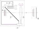
图1为成像元件1为投影显示元件的本发明成像器以及实施例1的系统示意图,FIG. 1 is a system schematic diagram of the imager of the present invention and
图2是在图1的基础上,将投影显示元件替换成拍摄感光元件的本发明成像器的系统示意图,Fig. 2 is a system schematic diagram of an imager of the present invention that replaces the projection display element with a photosensitive element on the basis of Fig. 1,
图3为实施例2的系统示意图,Fig. 3 is the system schematic diagram of
图4为实施例3的系统示意图,Fig. 4 is the system schematic diagram of
图5为实施例4的系统示意图,Fig. 5 is the system schematic diagram of
图6为第二等效像面4的一个振动周期的状态示意图,Fig. 6 is the state schematic diagram of one vibration period of the second
图7为成像镜组5进行机械变焦的原理示意图,FIG. 7 is a schematic diagram of the principle of mechanical zooming performed by the
图8为成像镜组5采用柔性变焦透镜的变焦原理示意图,FIG. 8 is a schematic diagram of the zooming principle of the
图9为振镜3与二维成像元件1成45°角度时,二者振幅对应关系示意图,9 is a schematic diagram of the corresponding relationship between the amplitudes of the
图10为振镜3数量为2个时,本发明的所述成像器的系统示意图,10 is a system schematic diagram of the imager of the present invention when the number of
附图标记如下:The reference numbers are as follows:
成像元件1,第一等效像面2,振镜3,第二等效像面4,成像镜组5,二维切面6,焦深扫描机构7。
具体实施方式Detailed ways
为了使本领域技术人员更好地理解本发明的技术方案,下面结合附图对本发明进行详细描述,本部分的描述仅是示范性和解释性,不应对本发明的保护范围有任何的限制作用。In order to make those skilled in the art better understand the technical solutions of the present invention, the present invention will be described in detail below with reference to the accompanying drawings. The description in this part is only exemplary and explanatory, and should not have any limiting effect on the protection scope of the present invention. .
参照图1至图10,本发明提供一种布拉格周期扫描式全息成像器,其内部包含有成像元件1、至少一个振镜3、成像镜组5以及焦深扫描机构7;1 to 10 , the present invention provides a Bragg period scanning holographic imager, which includes an
成像元件1用于提供多个不重合或者相互平行的第一等效像面2,第一等效像面2的数量为n,第一等效像面2可以是真实存在的物理,也可以是通过光学转化得到的虚像面或者实像面等,具体实现方式在申请号为202010029144.5的一种全固态全息投影器中有详细实现方案这里不做赘述;The
振镜3的位置与第一等效像面2的位置对应,用于将多个第一等效像面2光学转化为多个第二等效像面4,第二等效像面4为通过光学转化得到的虚像面或者实像面等,第一等效像面2和第二等效像面4的数量相等,均为n;The position of the
成像镜组5的位置与第二等效像面4相对应,用于光学成像并形成有多个二维切面6;The position of the
焦深扫描机构7与振镜3连接,用于控制振镜3的空间位置变动,实现对二维切面6进行体扫描,优选前后往复运动实现体扫描;The focal
这种扫描相当于3D画面的景深扫描,可以扫描出一个成像空间,这个空间内形成更密集的二维切面6的阵列或者是连续的3D画面,本发明优选采用控制各个部件进行周期性位置变动来实现周期性的体扫描。This scanning is equivalent to the depth-of-field scanning of a 3D picture, which can scan an imaging space, in which a denser array of two-
由于每一个二维切面6上均布满像素阵列(二维),经过体扫描后就可以形成三维像素阵列,这种设有振镜3的结构优点是,只要进行一个非常小范围内进行扫描就可以达到一个相对更大的等效扫描空间,而经过光学转化后可以把等效扫描空间进一步放大。比如第二等效像面4的运动范围为等效扫描范围(也就是第二等效像面4的面积乘以其垂直方向的扫描振幅的2倍,可以记为V等效),而实际扫描的运动范围为振镜3的运动范围(也就是振镜3的面积乘以其垂直方向的扫描振幅的2倍,可以记为V扫描),两者的比值优选设置为大于1.2(通过光学几何关系可以实现特定放大倍数的设置模式,这里不做赘述),从而达到一级放大的目的,而成像镜组5的光学转换可以进一步把等效扫描范围进一步放大,比如选用放大倍数大于5的镜头,进一步把成像空间放大到大于53倍。Since each two-
这种扫描系统的另一个优点是可以使二维成像元件1和成像镜组5等关键部件处于完全静止的状态,或者非常轻微的运动状态,从而使系统更加可靠。Another advantage of this scanning system is that the key components such as the two-
其中,成像元件1可以是投影显示元件,也可以是拍摄感光元件:Wherein, the
如图1,当以投影显示元件作为成像元件1时,本发明的扫描式成像器就作为全息投影器使用:As shown in Figure 1, when the projection display element is used as the
投影显示元件的光线经过振镜3和成像镜组5光学转化后于空间内形成多个二维切面6,并组成一个二维切面6的阵列,等效于成像镜组5直接把如图1和图2所示的、与二维切面6的阵列光学共轭的多个第一等效像面2和第二等效像面4投影出去的显示效果,通过焦深扫描机构7控制振镜3振动,优选周期性变动,使第一等效像面2和第二等效像面4与成像镜组5之间的相对位置或者整体位置发生周期性变动,空间内二维切面6的阵列随之也于焦深方向发生振动来进行体扫描,之前多层切面式、不连续的立体显示效果经过扫描后形成更密集的二维切面6的阵列或者是连续的3D画面,实现连续的3D显示效果;The light of the projection display element is optically transformed by the
而上述的二维切面6分别与第一等效像面2和第二等效像面4之间存在光学共轭,因此对二维切面6进行体扫描时,第一等效像面2和第二等效像面4也同时在进行体扫描,上述二维切面6为光学转化后的实像面,第一等效像面2和第二等效像面4为通过光学转化得到的虚像面;However, the above-mentioned two-
如图2,当以拍摄感光元件作为成像元件1时,本发明的扫描式成像器就作为全息拍摄器使用:As shown in Figure 2, when the photosensitive element is used as the
类似于上述的投影过程,由光路可逆原理,外部景物的光线经过振镜3和成像镜组5光学转化后于拍摄感光元件上生成多个实像二维切面6并被记录下来,等效于外部景物的光线经过成像镜组5光学成像后直接生成如图2所示的、与外部景物光学共轭的多个第一等效像面2和第二等效像面4的效果;Similar to the above-mentioned projection process, according to the principle of reversibility of the optical path, the light of the external scene is optically transformed by the
这点跟普通的摄像机工作原理非常相似,所不同的是普通相机只有一个感光芯片,只能记录与之对应的光学共轭处的景物信息,而本发明的拍摄感光元件内含有多个感光芯片,因此可以同时记录多个像,且每个像分别对应于不同景深的景物,达到类似切片3D式的拍摄记录。通过焦深扫描机构7控制拍摄感光元件和/或成像镜组5的空间位置变动,优选周期性变动,使第一等效像面2和第二等效像面4与成像镜组5之间的相对位置或者整体位置发生周期性变动,相应的与感光芯片、第一等效像面和第二等效像面4光学共轭的景深空间也发生周期性的扫描,使得景物不同景深处的信息分别被记录,从而记录下完整连续的3D场景,实现3D拍摄的目的,根据光路可逆,与第二等效像面4光学共轭的景深空间发生周期性的扫描的过程,第二等效像面4发生了相应的周期性扫描,而上述的第二等效像面4与二维切面6之间为等效关系,因此对第二等效像面4的扫描可以等效于对二维切面6的扫描,上述二维切面6为光学转化后的实像面,第一等效像面2和第二等效像面4为通过光学转化得到的虚像面。This is very similar to the working principle of an ordinary camera. The difference is that an ordinary camera has only one photosensitive chip and can only record the scene information at the corresponding optical conjugate, while the photographing photosensitive element of the present invention contains multiple photosensitive chips. , so multiple images can be recorded at the same time, and each image corresponds to scenes with different depths of field, achieving a 3D-like shooting record. The spatial position variation of the photographing photosensitive element and/or the
本发明通过设置的焦深扫描机构7控制振镜3的空间位置变动,从而使得与第一等效像面2对应的第二等效像面4与成像镜组5之间的相对位置发生变动,优选周期性变动,以实现对二维切面6的体扫描;比如,通过机械方式振镜3在空间中周期性往复扫描运动,即可在空间扫出一个连续的空间,实际应用中可以以一个固定的频率往复扫描,也可以根据显示内容需要使用不同的频率进行扫描,其中,扫描机构的设计属于本领域内公知常识,具体实现方式可以根据实际情况自行设计,这里不做赘述。The present invention controls the spatial position change of the
还可以进一步通过焦深扫描机构7控制成像镜组5的有效焦距周期性变动,也可以实现对二维切面6的体扫描,成像镜组5的有效焦距周期性变动可以通过改变成像镜组5内光学元件的相对位置和/或整体位置来实现(机械变焦),也可以在成像镜组5内设置具有变焦功能的液体变焦透镜和/或柔性变焦透镜来实现;The effective focal length of the
进一步地,焦深扫描机构7还可以分别与二维成像元件1和/或成像镜组5连接,用于控制二维成像元件1和/或成像镜组5的空间位置变动,实现二维切面6的体扫描,同样可以实现上述的3D成像的效果。Further, the focal
此外,除了进行单纯的一维景深扫描,还可以用三维扫描的方式进一步提升显示效果。比如,增加平行于等效像面的扫描,这样可以进一步增加横向分辨率,使画质更加细腻。In addition, in addition to simple one-dimensional depth-of-field scanning, three-dimensional scanning can be used to further improve the display effect. For example, increasing the scan parallel to the equivalent image plane can further increase the lateral resolution and make the image quality more delicate.
扫描机构的设计为本领域内的一般通识,可以根据实际应用场景自行设计这里不做赘述。The design of the scanning mechanism is a general knowledge in the field, and can be designed according to the actual application scenario and will not be repeated here.
下面以只包含一个振镜3、成像元件1为投影显示元件、第一等效像面2的数量n=3的本发明的全息成像器为实施例来对本发明作进一步的说明:The present invention is further described below by taking the holographic imager of the present invention which only includes one
实施例1Example 1
如图1,布拉格周期扫描式全息成像器包括分别设置于内部的投影显示元件、振镜3、成像镜组5和焦深扫描机构7,焦深扫描机构7与振镜3连接并控制振镜3空间位置的前后往复扫描(或者周期性变动),使得投影显示元件提供的第一等效像面2以及经过振镜3光学转化后的第二等效像面4与成像镜组5之间的相对位置发生周期性变动,与第二等效像面4光学共轭的二维切面6随之于焦深方向发生周期性变动,实现二维切面6的前后往复扫描,从而呈现连续的3D画面。As shown in Figure 1, the Bragg periodic scanning holographic imager includes a projection display element, a
实施例2Example 2
如图3,布拉格周期扫描式全息成像器包括分别设置于内部的投影显示元件、振镜3、成像镜组5和焦深扫描机构7,焦深扫描机构7分别与成像元件1和振镜3连接并控制二者的空间位置的周期性变动,使得投影显示元件提供的第一等效像面2以及经过振镜3光学转化后的第二等效像面4与成像镜组5之间的相对位置发生周期性变动,与第二等效像面4光学共轭的二维切面6随之于焦深方向发生周期性变动,实现二维切面6的前后往复扫描,从而呈现连续的3D画面。As shown in Figure 3, the Bragg period scanning holographic imager includes a projection display element, a
实施例3Example 3
如图4,布拉格周期扫描式全息成像器包括分别设置于内部的投影显示元件、振镜3、成像镜组5和焦深扫描机构7,焦深扫描机构7分别与振镜3和成像镜组5连接并控制二者的空间位置的周期性变动,使得投影显示元件提供的第一等效像面2以及经过振镜3光学转化后的第二等效像面4与成像镜组5之间的相对位置发生周期性变动,与第二等效像面4光学共轭的二维切面6随之于焦深方向发生周期性变动,实现二维切面6的前后往复扫描,从而呈现连续的3D画面。As shown in Figure 4, the Bragg period scanning holographic imager includes a projection display element, a
实施例4Example 4
如图5,布拉格周期扫描式全息成像器包括分别设置于内部的投影显示元件、振镜3、成像镜组5和焦深扫描机构7,焦深扫描机构7分别与投影显示元件、振镜3和成像镜组5连接并控制三者的空间位置的周期性变动,使得投影显示元件提供的第一等效像面2以及经过振镜3光学转化后的第二等效像面4与成像镜组5之间的相对位置发生周期性变动,与第二等效像面4光学共轭的二维切面6随之于焦深方向发生周期性变动,实现二维切面6的前后往复扫描,从而呈现连续的3D画面。As shown in FIG. 5, the Bragg period scanning holographic imager includes a projection display element, a
实施例5Example 5
布拉格周期扫描式全息成像器包括分别设置于内部的投影显示元件、振镜3、成像镜组5和焦深扫描机构7,焦深扫描机构7分别与振镜3和成像镜组5连接并控制振镜3的空间位置以及成像镜组5的有效焦深发生周期性变动,使得投影显示元件提供的第一等效像面2以及经过振镜3光学转化后的第二等效像面4与成像镜组5之间的相对位置发生周期性变动,与第二等效像面4光学共轭的二维切面6随之于焦深方向发生周期性变动,实现二维切面6的前后往复扫描,从而呈现连续的3D画面。The Bragg period scanning holographic imager includes a projection display element, a
实施例5中,焦深扫描机构7可以通过以下方式实现对成像镜组5的有效焦深的控制:In
如图7,焦深扫描机构7控制成像镜组5内设的多个光学元件的相对位置和/或整体位置发生变动(机械变焦),实现对成像镜组5的有效焦距周期性变动的控制;As shown in FIG. 7 , the focal
还可以在成像镜组5内设具有变焦功能的柔性变焦透镜,并通过焦深扫描机构7控制来柔性变焦透镜的焦距来实现对成像镜组5的有效焦距周期性变动的控制,柔性变焦透镜原理如图8所示,柔性变焦透镜还可以由其他具有变焦功能的透镜来替代,比如液体变焦透镜等;A flexible zoom lens with zoom function can also be provided in the
当然实施例3和实施例4中的成像镜组5也可以增加变焦功能,并通过焦深扫描机构7来统一调控,以实现二维切面6的前后往复扫描,另外,振镜3的数量也可以是多个,图10是振镜3的数量为2个的情况。Of course, the
实施例1~5分别体现了不同的二维切面6的前后往复扫描的实现方式,最终都达到了连续的3D显示效果。
本发明在实际应用时,本发明在实际应用时,焦深扫描机构7运作实现对二维切面6体扫描时,与二维切面6光学共轭的第一等效像面2和第二等效像面4也同时都在进行体扫描;When the present invention is in practical application, when the present invention is in practical application, the focal
通过焦深扫描机构7控制的振动与第一等效像面2和第二等效像面4的扫描是线性对应关系,而基于透镜成像规律,二维切面6于焦深方向上的扫描与第一等效像面2和第二等效像面4的扫描却不是线性对应关系,因此,相关设计参数要以第一等效像面2或第二等效像面4作为参照来设计才更方便:The vibration controlled by the focal
如图6,第二等效像面4于焦深方向上的振幅(即第二等效像面4于焦深方向偏离平衡位置的最大位移)为L1㎜,上述第二等效像面4的平衡位置为第二等效像面4的焦深方向振幅点与焦深反方向振幅点两个点之间的中点,而第二等效像面4的振幅点如图6所示:将第二等效像面4沿焦深方向的最大位移处定义为焦深方向振幅点、沿焦深反方向的最大位移处定义为焦深反方向振幅点;As shown in FIG. 6 , the amplitude of the second
因为振镜3的存在,通过振镜3光学转化后的第二等效像面4振幅L1应该与振镜3垂直方向的振幅之间存在几何对应关系,振镜3垂直方向的振幅为A㎜,需要说明的是,上述的振镜3垂直方向的振幅A应解释为振镜3在振动过程中,于垂直于其自身方向上偏离振镜3平衡位置的最大位移,而振镜3的平衡位置为振镜3振动的正反方向上最大位移的中点位置;Because of the existence of the
振镜3垂直方向的振幅为A与振镜3和二维成像元件1之间的夹角相关联,下面以振镜3和成像元件1的夹角为45°为例说明:The amplitude of the
如图9所示,振镜3的数量为1、振幅为A㎜,第二等效像面4的扫描振幅L1为2√2A㎜;As shown in FIG. 9 , the number of
振镜3的数量为2且相互平行设置,振动频率相同,振幅也均为A㎜,那么第二等效像面4的振幅L1为4√2A㎜;The number of
振镜3的数量为3且相互平行设置,振动频率相同,振幅也均为A㎜,那么第二等效像面4的振幅L1为6√2A㎜;The number of
以此类推,振镜3的数量为N且相互平行设置,频率相同,振幅也均为A㎜则那么第二等效像面4的振幅L1为2√2N*A㎜;By analogy, the number of
实际应用时,振镜3数量为多个,而且又不平行设置时,可以根据几何运算得出最终得出第二等效像面4沿焦深方向的振幅L1;In practical application, when the number of
多个第二等效像面4沿焦深方向分布深度即最靠近成像镜组5的第二等效像面4与离成像镜组5最远的第二等效像面4的中心距离为L2㎜,与第二等效像面4沿焦深方向的振幅L1应满足L1<L2,此时才能够使扫描的幅度相对更小。The depth distribution of the plurality of second equivalent image planes 4 along the focal depth direction, that is, the center distance between the second
考虑到只要相邻第二等效像面4之间的间隙通过扫描动作可以完全扫过即可实现连续的3D画面空间,所以扫描的振幅只要大于最大的相邻第二等效像面4之间的间距即可实现完整连续空间的扫描,因此,设计时可以优选:
实际应用时,为了表现更细腻的画面效果可以把扫描振幅做的更大一些或者对于深度分辨率追求不高的场景也可以小一些。In practical applications, the scanning amplitude can be made larger in order to express more delicate picture effects or smaller for scenes with low depth resolution.
实际应用时,焦深扫描机构7的扫描频率或者等效频率优选大于
在一定的空间内显示3D画面的时候,需要使焦平面在一定空间内前后扫描完成全空间画面的更新,所以3D画面的帧频就是景深扫描频率。When displaying a 3D image in a certain space, the focal plane needs to be scanned back and forth in a certain space to complete the update of the full-space image, so the frame rate of the 3D image is the depth of field scanning frequency.
此外,还有一种特殊情况,就是当显示空间发生整体运动时,比如从近景移动到远景的过程,在切换的过程中景深往往只需要单向运动无需往复扫描,那么此时也就无景深扫描的概念,但是显示景深切换过程同样需要在一个比较合适的速度内完成,否则容易出现画面跳动或者拖尾的情况。针对这种情况我们引入等效频率的概念:等效频率是指等效像面相对于成像镜组5进行单向运动时,运动距离等于相邻第二等效像面4之间的最大相邻间距的过程中所用时间的倒数。In addition, there is also a special case, that is, when the overall movement occurs in the display space, such as the process of moving from a close view to a distant view, in the process of switching, the depth of field often only needs one-way movement without reciprocating scanning, so there is no depth of field scanning at this time. However, the process of displaying the depth of field switching also needs to be completed within a relatively suitable speed, otherwise the picture will be prone to jumping or trailing. In view of this situation, we introduce the concept of equivalent frequency: equivalent frequency means that when the equivalent image plane moves in one direction relative to the
对于采用变焦方式进行扫描的情况可以采用等效焦距变动过程中从初始焦距再次变为该焦距的时间的倒数(或者是从最大焦距再次变为最大焦距的时间间隔的倒数),初始焦距指的是焦深扫描机构7未运作时,成像镜组5的焦距。当然,也可以通过测量投影焦平面连续两次沿同一方向上扫过空间某一位置的时间间隔的倒数。In the case of scanning by zooming, the reciprocal of the time from the initial focal length to the focal length (or the reciprocal of the time interval from the maximum focal length to the maximum focal length) in the process of changing the equivalent focal length can be used. The initial focal length refers to It is the focal length of the
实际应用时发现,第一等效像面2和第二等效像面4的数量n越大,二维切面相对就会越密集,在一般显示情况下基本上也可以呈现出比较好的立体显示效果,因此只需要在显示内容的整体景深发生较大的变动时,才需要通过焦深扫描动作重新匹配显示空间的焦深。比如,电影画面的显示内容从室内场景转换到空旷的室外场景或者外太空星系场景,此时,显示的焦深发生较大幅度的变动,通常这种大焦深差异场景切换通常都是在多帧图像内完成的,转换过程相对比较缓慢,所以只需要显示系统能够比较缓慢的实现焦深切换即可,所以扫描频率(等效频率)可以远小于3D视频的帧频。这样也可以大幅度降低对计算和控制系统的要求,使得系统更加稳定;In practical application, it is found that the larger the number n of the first
但是另一方面,n越大必然造成相应部件的总质量增加,系统的固有频率就会降低,这样也就比较难以实现较高的扫描频率,所以必须降低扫描频率下限来保护系统的可靠性。But on the other hand, a larger n will inevitably increase the total mass of the corresponding components, and the natural frequency of the system will decrease, which makes it more difficult to achieve a higher scanning frequency. Therefore, the lower limit of the scanning frequency must be lowered to protect the reliability of the system.
通常显示画面在一个相对比较小的范围内的,比如室内场景,此时等效像面的投影空间有可能完全可以满足这种小空间范围的显示,这时候及时不进行焦深扫描动作也可以比较真实的还原3D场景,或者为了使显示效果更细腻,只需要进行非常小的振幅的扫描即可。Usually the display screen is in a relatively small range, such as an indoor scene. At this time, the projection space of the equivalent image plane may fully meet the display in such a small space range. At this time, it is also possible not to perform the focal depth scanning action in time. To restore the 3D scene more realistically, or to make the display effect more delicate, only a very small amplitude scan is required.
只有在显示景深变动范围较大,或者景深整体发生较大变动时,焦深扫描需要做较大振幅的扫描或者整体平移。Only when the display depth of field changes in a large range, or the overall depth of field changes greatly, the focal depth scan needs to be scanned with a larger amplitude or an overall translation.
需要说明的是,很多时候景深切换并不需要实现一个完整的扫描周期。It should be noted that, in many cases, depth of field switching does not need to implement a complete scanning cycle.
比如画面场景由近景缓慢切换到远景,然后停留在远景一段时间,那么焦深扫描只需要相应的调整画面景深即可,此时可以使用等效频率概念。For example, the scene of the picture is slowly switched from the near view to the distant view, and then stays in the distant view for a period of time, then the depth of focus scan only needs to adjust the depth of field of the picture accordingly, and the concept of equivalent frequency can be used at this time.
以下是几种实际测试时用户的反馈情况:The following is the feedback from users during several actual tests:

从数据来看对于一般要求不是特别高的应用场景,扫描频率(或者等效频率)优选大于
当然,为了进一步提高3D显示效果,提高综合性能得分,对于一些特殊应用场景,可以优选n≥2,扫描频率
而对于一些追求极致体验的用户可以优选n≥3,扫描频率
通常人眼的深度分辨率远低于横向分辨率,所以即使深度方向上像素间距较大也不会造成分辨失真,因此投影画面在深度方向上的像素间距可以设置大一些,从而可以在有效降低设备和工艺成本的条件下,投射出非常真实的3D画面。Usually the depth resolution of the human eye is much lower than the lateral resolution, so even if the pixel pitch in the depth direction is large, it will not cause resolution distortion. Therefore, the pixel pitch of the projection image in the depth direction can be set larger, which can effectively reduce the Under the condition of equipment and process cost, a very real 3D picture is projected.
另外,成像元件1的质量Mg,与第一等效像面2数量n之间满足
这里以全息投影器为例进行说明,通常全息投影器的主要应用领域是几何全息显示系统(参考申请号为201910875975.1的专利文献),而这种系统中全息投影器往往需要其处于一种运动状态,因此其质量就不能太大,否则控制一个质量过大的部件运动,由于质量带来的惯性也非常大进而操控难度极大,且能耗极大,另一方面对于支撑结构会造成很大的负担,整个系统就会非常笨重而不实用。因此需要对其质量进行合理设计。理想情况下,整体质量越小越好,但是第一等效像面2必须依赖于物理实体存在,这样第一等效像面2的数量越大,整体质量也会越大。如果想设计尽可能轻巧的全息投影器,那么必然需要牺牲第一等效像面2数量,如果想获得更密集的第一等效像面2,就不得不接收质量的增加,两者不能同时达到最优。本发明给出了一种权衡两者关系的设计准则,即
这个设计关系式间接限定了总质量的大小,给出了数量不同的第一等效像面2的情况下全息投影器的上限边界,超出此上限边界时,制作出的全息投影器实用性就会很差。比如对于客厅显示,使用11个第一等效像面2来进行景深表现,就可以达达到非常完美的显示效果了,而客厅内运动物体的质量最大不要超过5000g,否则一方面有可能存在对人员的安全隐患,另一方面,支撑结构会非常笨重,占用大量的空间,而且不够美观,对于此边界情况
此外,对于桌面办公类场景,设计时尽可能优选更为严格的设计规范,优选
进一步地,优选
进一步地,优选
另外,为了追求最优的综合显示效果,需要对各个组件进行精细的设计。In addition, in order to pursue the optimal comprehensive display effect, each component needs to be carefully designed.
一方面需要提高大视角显示能力,所以振镜3的面积尽可能大一些,这样才能更好的利用镜头的有效光学面积。另一方面还需要尽可能保证优异的景深细节表现能力,也就是需要提高系统扫描频率,对于机械扫描系统,扫描的最佳配置是利用其固有频率进行扫描,而通常机械系统的固有频率与振动部件的质量之间存在负相关关系。所以镜片的质量需要做的小一些,相应的其面积也会小一些。此外,对于一个产品,提高系统的稳定性同样非常重要,扫描过程中振动的幅度越小,系统越接近固态,稳定性越好,但是振幅太小,景深表现范围又会收到制约,难以完成超大景深的表现。此外,如果运动部件的质量和振幅都比较大时,对系统的反冲作用会很明显,容易出现画面抖动等情况。On the one hand, it is necessary to improve the display capability of a large viewing angle, so the area of the
综上,对于这种全新的方案,需要同时考虑有效光学利用面积、扫描频率、扫描振幅三个相互对立的指标,而三者不能够同时达到最优设计,需要进行一定的权衡、优化来获得一个比较优异的综合性能。To sum up, for this brand-new scheme, it is necessary to consider the three mutually opposing indicators of effective optical utilization area, scanning frequency, and scanning amplitude at the same time, and the three cannot achieve the optimal design at the same time, and certain trade-offs and optimizations are required to obtain A relatively excellent overall performance.
由于此前并无任何可借鉴的设计经验,所以虽然成像原理比较容易理解,但是真正设计出性能比较优异的产品还是有不小的困难。所以本发明给出一个容易实施的指导设计的规则,来帮助本领域的一般从业人员设计出性能优异的产品。Since there is no previous design experience that can be used for reference, although the imaging principle is relatively easy to understand, it is still difficult to really design a product with excellent performance. Therefore, the present invention provides an easy-to-implement design guideline to help ordinary practitioners in the field to design products with excellent performance.
通常对于一个特定的透镜成像应用场景,主镜片的厚度范围非常窄,比如单反相机,最外侧镜片的厚度(中心厚度)一般在1~5mm之间,实际情况不考虑一些极端特殊案例,该范围会更窄,这主要是受成像镜片设计规律制约的。所以,成像镜片的质量往往主要取决于其口径的大小。为了与成像镜头相匹配,那么振镜3的面积也需要在一个合适的范围内。此外,还需要考虑扫描过程中因振动带来的镜面变形问题,也就是镜片的刚度问题,即对于特定面积的振镜3需要通过对其厚度的设计来保证刚度足够,因此扫描镜的体积也在一个非常小的范围内被确定下来,通常镜片的材质密度差异比较小,所以其质量也可以进一步被确定在一个合理的范围内。Usually, for a specific lens imaging application scenario, the thickness range of the main lens is very narrow. For example, in a single-lens reflex camera, the thickness of the outermost lens (central thickness) is generally between 1 and 5 mm. The actual situation does not consider some extreme special cases. It will be narrower, which is mainly restricted by the design law of the imaging lens. Therefore, the quality of the imaging lens is often mainly determined by the size of its aperture. In order to match with the imaging lens, the area of the
通过以上理论分析权衡各个方面性能,结合实验组装测试本发明确定出在保证一定视角的前提下,能够较好的表现景深细节效果的参数设计空间(由于本系统的设计主要针对3D成像领域,所以设计过程中需要优先保证景深表现能力),任意一个所述振镜3的质量为MNg、振幅为A㎜,全息成像器最外侧镜片的质量为mg,满足::
需要说明的是对于采用多个振镜3的情况,距离成像镜头最外侧镜片最近的扫描镜片的质量定义为M1g,其他扫描镜片的质量依次定义为M2g、M3g、M4g……Mng,并且满足:
对于不同的用户,需求的场景是不一样的,他们的要求也不一样。针对游戏用户对于场景运动速度要求较高,优选


以下案例以最外侧镜片质量为80g为例进行实验测试,具体如下表:The following cases take the mass of the outermost lens as an example of 80g for experimental testing, as shown in the following table:

虽然,以上实施例是中最外侧镜片的质量是80g,但是设计时可以考虑把系统进行整体缩放,即可得到其他尺寸、质量的设计,这一点非常类似于流体设计中情况,流体中只要流体的雷诺数相似,那么其数学解就会非常相似,因此在大模型无法实现的情况下通常是使用相同雷诺数的小模型进行实验测试的。事实上,以上实验方案,我们也在50g,20g,10g,5g,2g等情况下验证过,用户体验反馈与上述表内反馈结果一致,进一步证明了设计公式的通用性。Although, in the above embodiment, the mass of the outermost lens is 80g, it can be considered to scale the system as a whole to obtain designs of other sizes and masses, which is very similar to the situation in the fluid design, as long as the fluid is in the fluid If the Reynolds numbers are similar, the mathematical solutions will be very similar, so when the large model cannot be achieved, it is usually tested experimentally using a small model with the same Reynolds number. In fact, we have also verified the above experimental scheme under 50g, 20g, 10g, 5g, 2g, etc. The user experience feedback is consistent with the feedback results in the above table, which further proves the versatility of the design formula.
此外,从以上实施反馈还可以总结出一个相对粗糙但是也比较有效的简化设计规则,即
通常人眼的深度分辨率远低于横向分辨率,所以即使深度方向上像素间距较大也不会造成分辨失真,因此投影画面在深度方向上的像素间距可以设置大一些,从而可以在有效降低设备和工艺成本的条件下,投射出非常真实的3D画面。Usually the depth resolution of the human eye is much lower than the lateral resolution, so even if the pixel pitch in the depth direction is large, it will not cause resolution distortion. Therefore, the pixel pitch of the projection image in the depth direction can be set larger, which can effectively reduce the Under the condition of equipment and process cost, a very real 3D picture is projected.
成像元件1内可以同时设有若干投影显示芯片和拍摄感光芯片,以实现投影和拍摄的双功能。The
需要说明的是,投影显示元件作为成像元件1的本发明的布拉格周期扫描式全息成像器是作为全息投影器来使用的,拍摄感光元件作为成像元件1的本发明的布拉格周期扫描式全息成像器是作为全息拍摄器来使用的,而以上的设计说明主要是针对全息投影器的情况来进行的解释说明,但是由于全息拍摄器的应用情况非常相似,基于光路可逆原理,全息投影器需要考虑的问题,全息拍摄器同样也会遇到,因此以上设计说明同样适用于全息拍摄器。It should be noted that the Bragg period scanning holographic imager of the present invention in which the projection display element is used as the
以上内容是结合具体的优选实施方式对本发明所作的进一步详细说明,不能认定本发明的具体实施只局限于这些说明。对于本发明所属技术领域的普通技术人员来说,在不脱离本发明构思的前提下,还可以做出若干简单推演或替换,都应当视为属于本发明的保护范围。The above content is a further detailed description of the present invention in combination with specific preferred embodiments, and it cannot be considered that the specific implementation of the present invention is limited to these descriptions. For those of ordinary skill in the technical field of the present invention, without departing from the concept of the present invention, some simple deductions or substitutions can be made, which should be regarded as belonging to the protection scope of the present invention.
Claims (10)


Priority Applications (2)
| Application Number | Priority Date | Filing Date | Title |
|---|---|---|---|
| CN202010401524.7ACN111399331B (en) | 2020-05-13 | 2020-05-13 | A Bragg period scanning holographic imager |
| PCT/CN2021/093251WO2021228120A1 (en) | 2020-05-13 | 2021-05-12 | Scanning-type holographic imaging device and related system |
Applications Claiming Priority (1)
| Application Number | Priority Date | Filing Date | Title |
|---|---|---|---|
| CN202010401524.7ACN111399331B (en) | 2020-05-13 | 2020-05-13 | A Bragg period scanning holographic imager |
Publications (2)
| Publication Number | Publication Date |
|---|---|
| CN111399331Atrue CN111399331A (en) | 2020-07-10 |
| CN111399331B CN111399331B (en) | 2025-06-24 |
Family
ID=71433829
Family Applications (1)
| Application Number | Title | Priority Date | Filing Date |
|---|---|---|---|
| CN202010401524.7AActiveCN111399331B (en) | 2020-05-13 | 2020-05-13 | A Bragg period scanning holographic imager |
Country Status (1)
| Country | Link |
|---|---|
| CN (1) | CN111399331B (en) |
Cited By (2)
| Publication number | Priority date | Publication date | Assignee | Title |
|---|---|---|---|---|
| WO2021228120A1 (en)* | 2020-05-13 | 2021-11-18 | 荆门市探梦科技有限公司 | Scanning-type holographic imaging device and related system |
| CN113848654A (en)* | 2021-09-18 | 2021-12-28 | 湖南美景创意文化建设有限公司 | Exhibition room dielectric-free aerial imaging display screen with gesture interaction function |
Citations (13)
| Publication number | Priority date | Publication date | Assignee | Title |
|---|---|---|---|---|
| US5954414A (en)* | 1996-08-23 | 1999-09-21 | Tsao; Che-Chih | Moving screen projection technique for volumetric three-dimensional display |
| JP2001249300A (en)* | 2000-03-06 | 2001-09-14 | Anritsu Corp | Optical scanner |
| JP2003066361A (en)* | 2001-08-23 | 2003-03-05 | Ricoh Co Ltd | Optical deflector and method of manufacturing the same, optical scanning module, optical scanning device, image forming device, image display device |
| CN101271194A (en)* | 2007-03-19 | 2008-09-24 | 株式会社理光 | Light scanning apparatus and imaging apparatus |
| CN102879995A (en)* | 2011-07-10 | 2013-01-16 | 财团法人工业技术研究院 | Display device |
| CN103439859A (en)* | 2013-07-22 | 2013-12-11 | 秦皇岛视听机械研究所 | Ring screen showing or projecting system unit based on two anisotropy fish-eye lenses |
| CN103606181A (en)* | 2013-10-16 | 2014-02-26 | 北京航空航天大学 | Microscopic three-dimensional reconstruction method |
| CN104317059A (en)* | 2014-11-14 | 2015-01-28 | 山东理工大学 | Three-dimensional real-time phantom display system and display method thereof |
| US20160150201A1 (en)* | 2014-11-20 | 2016-05-26 | Lucio Kilcher | Virtual image generator |
| CN107632403A (en)* | 2016-07-18 | 2018-01-26 | 杨军 | Three-dimensional imaging display instrument |
| CN110225328A (en)* | 2019-06-20 | 2019-09-10 | 金陵科技学院 | A kind of city intelligent virtual imaging apparatus, imaging system and its modeling method |
| CN111105735A (en)* | 2020-01-13 | 2020-05-05 | 荆门市探梦科技有限公司 | An all-solid-state holographic projector |
| CN212515339U (en)* | 2020-05-13 | 2021-02-09 | 荆门市探梦科技有限公司 | Bragg period scanning type holographic imager |
- 2020
- 2020-05-13CNCN202010401524.7Apatent/CN111399331B/enactiveActive
Patent Citations (13)
| Publication number | Priority date | Publication date | Assignee | Title |
|---|---|---|---|---|
| US5954414A (en)* | 1996-08-23 | 1999-09-21 | Tsao; Che-Chih | Moving screen projection technique for volumetric three-dimensional display |
| JP2001249300A (en)* | 2000-03-06 | 2001-09-14 | Anritsu Corp | Optical scanner |
| JP2003066361A (en)* | 2001-08-23 | 2003-03-05 | Ricoh Co Ltd | Optical deflector and method of manufacturing the same, optical scanning module, optical scanning device, image forming device, image display device |
| CN101271194A (en)* | 2007-03-19 | 2008-09-24 | 株式会社理光 | Light scanning apparatus and imaging apparatus |
| CN102879995A (en)* | 2011-07-10 | 2013-01-16 | 财团法人工业技术研究院 | Display device |
| CN103439859A (en)* | 2013-07-22 | 2013-12-11 | 秦皇岛视听机械研究所 | Ring screen showing or projecting system unit based on two anisotropy fish-eye lenses |
| CN103606181A (en)* | 2013-10-16 | 2014-02-26 | 北京航空航天大学 | Microscopic three-dimensional reconstruction method |
| CN104317059A (en)* | 2014-11-14 | 2015-01-28 | 山东理工大学 | Three-dimensional real-time phantom display system and display method thereof |
| US20160150201A1 (en)* | 2014-11-20 | 2016-05-26 | Lucio Kilcher | Virtual image generator |
| CN107632403A (en)* | 2016-07-18 | 2018-01-26 | 杨军 | Three-dimensional imaging display instrument |
| CN110225328A (en)* | 2019-06-20 | 2019-09-10 | 金陵科技学院 | A kind of city intelligent virtual imaging apparatus, imaging system and its modeling method |
| CN111105735A (en)* | 2020-01-13 | 2020-05-05 | 荆门市探梦科技有限公司 | An all-solid-state holographic projector |
| CN212515339U (en)* | 2020-05-13 | 2021-02-09 | 荆门市探梦科技有限公司 | Bragg period scanning type holographic imager |
Cited By (2)
| Publication number | Priority date | Publication date | Assignee | Title |
|---|---|---|---|---|
| WO2021228120A1 (en)* | 2020-05-13 | 2021-11-18 | 荆门市探梦科技有限公司 | Scanning-type holographic imaging device and related system |
| CN113848654A (en)* | 2021-09-18 | 2021-12-28 | 湖南美景创意文化建设有限公司 | Exhibition room dielectric-free aerial imaging display screen with gesture interaction function |
Also Published As
| Publication number | Publication date |
|---|---|
| CN111399331B (en) | 2025-06-24 |
Similar Documents
| Publication | Publication Date | Title |
|---|---|---|
| US11935206B2 (en) | Systems and methods for mixed reality | |
| Stern et al. | Three-dimensional image sensing, visualization, and processing using integral imaging | |
| Xia et al. | Time-multiplexed multi-view three-dimensional display with projector array and steering screen | |
| TW200537126A (en) | Three-dimensional display using variable focusing lens | |
| WO2007069099A2 (en) | Optical system for 3-dimensional display | |
| CN110879478B (en) | Integrated imaging 3D display device based on compound lens array | |
| Chen et al. | Light field display with ellipsoidal mirror array and single projector | |
| CN111399331A (en) | A Bragg Periodic Scanning Holographic Imager | |
| Brar et al. | Laser-based head-tracked 3D display research | |
| EP1083757A2 (en) | Stereoscopic image display apparatus | |
| CN109660786A (en) | A kind of naked eye 3D three-dimensional imaging and observation method | |
| CN111818324A (en) | A device and method for generating a three-dimensional large viewing angle light field | |
| CN211698579U (en) | Micro-scanning holographic imager | |
| CN101137925A (en) | 3D image capturing camera and non-stereoscopic 3D viewing apparatus without glasses | |
| JP3403048B2 (en) | Three-dimensional image reproducing device and three-dimensional subject information input device | |
| CN111399333A (en) | Bragg period scanning type holographic imager | |
| CN212515339U (en) | Bragg period scanning type holographic imager | |
| CN111399332A (en) | Microscanning Holographic Imager | |
| CN211698580U (en) | Bragg period scanning type holographic imager | |
| KR20230003245A (en) | Display devices, systems, and methods | |
| Surman et al. | MUTED and HELIUM3D autostereoscopic displays | |
| JP3756481B2 (en) | 3D display device | |
| Surman et al. | Glasses-free 3-D and augmented reality display advances: from theory to implementation | |
| CN110908133A (en) | An integrated imaging 3D display device based on a dihedral corner mirror array | |
| JP2004226928A (en) | Stereoscopic picture display device |
Legal Events
| Date | Code | Title | Description |
|---|---|---|---|
| PB01 | Publication | ||
| PB01 | Publication | ||
| SE01 | Entry into force of request for substantive examination | ||
| SE01 | Entry into force of request for substantive examination | ||
| CB02 | Change of applicant information | Country or region after:China Address after:448000 building c2-b1, No.39 Jingnan Avenue, Duodao District, Jingmen City, Hubei Province Applicant after:JINGMEN CITY DREAM EXPLORING TECHNOLOGY Co.,Ltd. Address before:448000 shops 101, 201-111211118, 218-128 and 228, 1F and 2F, building c5-5, Renmin Wanfu business city, 201 Peigong Avenue, Duodao District, Jingmen City, Hubei Province Applicant before:JINGMEN CITY DREAM EXPLORING TECHNOLOGY Co.,Ltd. Country or region before:China | |
| CB02 | Change of applicant information | ||
| GR01 | Patent grant | ||
| GR01 | Patent grant |