CN111386245A - Fluid Handling Modules - Google Patents
Fluid Handling ModulesDownload PDFInfo
- Publication number
- CN111386245A CN111386245ACN201980003018.8ACN201980003018ACN111386245ACN 111386245 ACN111386245 ACN 111386245ACN 201980003018 ACN201980003018 ACN 201980003018ACN 111386245 ACN111386245 ACN 111386245A
- Authority
- CN
- China
- Prior art keywords
- fluid
- light
- light source
- source module
- module
- Prior art date
- Legal status (The legal status is an assumption and is not a legal conclusion. Google has not performed a legal analysis and makes no representation as to the accuracy of the status listed.)
- Pending
Links
Images


Classifications
- C—CHEMISTRY; METALLURGY
- C02—TREATMENT OF WATER, WASTE WATER, SEWAGE, OR SLUDGE
- C02F—TREATMENT OF WATER, WASTE WATER, SEWAGE, OR SLUDGE
- C02F1/00—Treatment of water, waste water, or sewage
- C02F1/30—Treatment of water, waste water, or sewage by irradiation
- C02F1/32—Treatment of water, waste water, or sewage by irradiation with ultraviolet light
- C02F1/325—Irradiation devices or lamp constructions
- A—HUMAN NECESSITIES
- A61—MEDICAL OR VETERINARY SCIENCE; HYGIENE
- A61L—METHODS OR APPARATUS FOR STERILISING MATERIALS OR OBJECTS IN GENERAL; DISINFECTION, STERILISATION OR DEODORISATION OF AIR; CHEMICAL ASPECTS OF BANDAGES, DRESSINGS, ABSORBENT PADS OR SURGICAL ARTICLES; MATERIALS FOR BANDAGES, DRESSINGS, ABSORBENT PADS OR SURGICAL ARTICLES
- A61L9/00—Disinfection, sterilisation or deodorisation of air
- A61L9/16—Disinfection, sterilisation or deodorisation of air using physical phenomena
- A61L9/18—Radiation
- A61L9/20—Ultraviolet radiation
- A61L9/205—Ultraviolet radiation using a photocatalyst or photosensitiser
- F—MECHANICAL ENGINEERING; LIGHTING; HEATING; WEAPONS; BLASTING
- F21—LIGHTING
- F21V—FUNCTIONAL FEATURES OR DETAILS OF LIGHTING DEVICES OR SYSTEMS THEREOF; STRUCTURAL COMBINATIONS OF LIGHTING DEVICES WITH OTHER ARTICLES, NOT OTHERWISE PROVIDED FOR
- F21V29/00—Protecting lighting devices from thermal damage; Cooling or heating arrangements specially adapted for lighting devices or systems
- F21V29/50—Cooling arrangements
- F21V29/502—Cooling arrangements characterised by the adaptation for cooling of specific components
- F21V29/503—Cooling arrangements characterised by the adaptation for cooling of specific components of light sources
- F—MECHANICAL ENGINEERING; LIGHTING; HEATING; WEAPONS; BLASTING
- F21—LIGHTING
- F21V—FUNCTIONAL FEATURES OR DETAILS OF LIGHTING DEVICES OR SYSTEMS THEREOF; STRUCTURAL COMBINATIONS OF LIGHTING DEVICES WITH OTHER ARTICLES, NOT OTHERWISE PROVIDED FOR
- F21V29/00—Protecting lighting devices from thermal damage; Cooling or heating arrangements specially adapted for lighting devices or systems
- F21V29/50—Cooling arrangements
- F21V29/70—Cooling arrangements characterised by passive heat-dissipating elements, e.g. heat-sinks
- A—HUMAN NECESSITIES
- A61—MEDICAL OR VETERINARY SCIENCE; HYGIENE
- A61L—METHODS OR APPARATUS FOR STERILISING MATERIALS OR OBJECTS IN GENERAL; DISINFECTION, STERILISATION OR DEODORISATION OF AIR; CHEMICAL ASPECTS OF BANDAGES, DRESSINGS, ABSORBENT PADS OR SURGICAL ARTICLES; MATERIALS FOR BANDAGES, DRESSINGS, ABSORBENT PADS OR SURGICAL ARTICLES
- A61L2209/00—Aspects relating to disinfection, sterilisation or deodorisation of air
- A61L2209/10—Apparatus features
- C—CHEMISTRY; METALLURGY
- C02—TREATMENT OF WATER, WASTE WATER, SEWAGE, OR SLUDGE
- C02F—TREATMENT OF WATER, WASTE WATER, SEWAGE, OR SLUDGE
- C02F2201/00—Apparatus for treatment of water, waste water or sewage
- C02F2201/32—Details relating to UV-irradiation devices
- C02F2201/322—Lamp arrangement
- C02F2201/3222—Units using UV-light emitting diodes [LED]
- C—CHEMISTRY; METALLURGY
- C02—TREATMENT OF WATER, WASTE WATER, SEWAGE, OR SLUDGE
- C02F—TREATMENT OF WATER, WASTE WATER, SEWAGE, OR SLUDGE
- C02F2201/00—Apparatus for treatment of water, waste water or sewage
- C02F2201/32—Details relating to UV-irradiation devices
- C02F2201/322—Lamp arrangement
- C02F2201/3227—Units with two or more lamps
- C—CHEMISTRY; METALLURGY
- C02—TREATMENT OF WATER, WASTE WATER, SEWAGE, OR SLUDGE
- C02F—TREATMENT OF WATER, WASTE WATER, SEWAGE, OR SLUDGE
- C02F2201/00—Apparatus for treatment of water, waste water or sewage
- C02F2201/32—Details relating to UV-irradiation devices
- C02F2201/322—Lamp arrangement
- C02F2201/3228—Units having reflectors, e.g. coatings, baffles, plates, mirrors
- C—CHEMISTRY; METALLURGY
- C02—TREATMENT OF WATER, WASTE WATER, SEWAGE, OR SLUDGE
- C02F—TREATMENT OF WATER, WASTE WATER, SEWAGE, OR SLUDGE
- C02F2303/00—Specific treatment goals
- C02F2303/04—Disinfection
- C—CHEMISTRY; METALLURGY
- C02—TREATMENT OF WATER, WASTE WATER, SEWAGE, OR SLUDGE
- C02F—TREATMENT OF WATER, WASTE WATER, SEWAGE, OR SLUDGE
- C02F2305/00—Use of specific compounds during water treatment
- C02F2305/10—Photocatalysts
- F—MECHANICAL ENGINEERING; LIGHTING; HEATING; WEAPONS; BLASTING
- F21—LIGHTING
- F21Y—INDEXING SCHEME ASSOCIATED WITH SUBCLASSES F21K, F21L, F21S and F21V, RELATING TO THE FORM OR THE KIND OF THE LIGHT SOURCES OR OF THE COLOUR OF THE LIGHT EMITTED
- F21Y2115/00—Light-generating elements of semiconductor light sources
- F21Y2115/10—Light-emitting diodes [LED]
Landscapes
- Health & Medical Sciences (AREA)
- Life Sciences & Earth Sciences (AREA)
- Engineering & Computer Science (AREA)
- Chemical & Material Sciences (AREA)
- Toxicology (AREA)
- Organic Chemistry (AREA)
- Water Supply & Treatment (AREA)
- Environmental & Geological Engineering (AREA)
- Hydrology & Water Resources (AREA)
- General Health & Medical Sciences (AREA)
- Veterinary Medicine (AREA)
- Public Health (AREA)
- Animal Behavior & Ethology (AREA)
- Epidemiology (AREA)
- General Engineering & Computer Science (AREA)
- Chemical Kinetics & Catalysis (AREA)
- Physical Water Treatments (AREA)
- Apparatus For Disinfection Or Sterilisation (AREA)
- Instantaneous Water Boilers, Portable Hot-Water Supply Apparatuses, And Control Of Portable Hot-Water Supply Apparatuses (AREA)
Abstract
Description
Translated fromChinese技术领域technical field
本发明涉及一种流体处理模组。The present invention relates to a fluid processing module.
背景技术Background technique
最近,商业化引起的污染正在加重,由此对环境的关注度在增加的同时,乐活趋势趋势也在扩散中。由此,对干净的水或者干净的空气的需求逐渐变多,正在开发与能够提供干净的水以及干净的空气的水处理装置、空气净化器等有关的多种产品。Recently, pollution caused by commercialization is increasing, and the environmental concern is increasing, and the trend of LOHAS is also spreading. As a result, the demand for clean water or clean air is gradually increasing, and various products related to water treatment apparatuses, air purifiers, and the like that can provide clean water and clean air are being developed.
发明内容SUMMARY OF THE INVENTION
本发明的目的在于,提供一种有效处理空气或者水之类的流体的装置。An object of the present invention is to provide an apparatus for efficiently treating fluids such as air or water.
根据本申请的实施例的流体处理模组包括:排管,提供流体移动的通道,并具有流入口和排出口;光源模组,包括基板和至少一个发光元件,所述发光元件设置在所述基板的前面上,并将处理所述流体的光向所述排管内照射;反射器,设置在所述排管内,对于所述光具有比所述排管高的反射率,并反射从所述光源模组射出的所述光;以及散热板,与所述基板的背面接触,以散发所述光源模组的热。所述流入口和所述排出口中至少一个设置为多个,以控制向所述排管内移动的所述流体的移动速度以及移动方向,所述散热板具有比所述基板的热传导率大的热传导率。A fluid processing module according to an embodiment of the present application includes: a drain pipe, which provides a channel for fluid movement, and has an inflow port and a discharge port; on the front of the substrate, and irradiates the light for processing the fluid into the row; a reflector, disposed in the row, has a higher reflectivity for the light than the row, and reflects the light from the row the light emitted by the light source module; and a heat dissipation plate, in contact with the back surface of the base plate, to dissipate the heat of the light source module. At least one of the inflow port and the discharge port is provided in plural to control the moving speed and moving direction of the fluid moving into the exhaust pipe, and the heat dissipation plate has a thermal conductivity larger than that of the substrate. Rate.
根据本发明的一实施例,可以是,所述散热板具有比所述基板的面积大的面积。According to an embodiment of the present invention, the heat dissipation plate may have an area larger than that of the substrate.
根据本发明的一实施例,可以是,所述散热板由金属构成。According to an embodiment of the present invention, the heat dissipation plate may be made of metal.
根据本发明的一实施例,可以是,所述流入口和所述排出口的数量可以互不相同。According to an embodiment of the present invention, the numbers of the inflow ports and the discharge ports may be different from each other.
根据本发明的一实施例,可以是,所述排管具有沿长度方向延伸的主体和分别沿所述主体的长度方向配置的第一端部和第二端部。According to an embodiment of the present invention, the row pipe may have a main body extending in the longitudinal direction, and a first end portion and a second end portion respectively arranged in the longitudinal direction of the main body.
根据本发明的一实施例,可以是,所述散热板具有比所述主体的直径更大的直径。According to an embodiment of the present invention, the heat dissipation plate may have a diameter larger than that of the main body.
根据本发明的一实施例,可以是,所述流入口和所述排出口设置在彼此不同的端部侧。According to an embodiment of the present invention, the inflow port and the discharge port may be provided on end portions different from each other.
根据本发明的一实施例,可以是,当从所述排管的长度方向观察时,所述流入口和所述排出口将所述排管的中心位于中间彼此沿相同的方向与所述排管连接。According to an embodiment of the present invention, when viewed from the longitudinal direction of the row of pipes, the inflow port and the discharge port may have the center of the row of pipes located in the middle of each other in the same direction as the row of pipes. Tube connection.
根据本发明的一实施例,可以是,当从所述排管的长度方向观察时,所述流入口和所述排出口彼此沿不同的方向与所述排管连接。According to an embodiment of the present invention, when viewed from the longitudinal direction of the row pipe, the inflow port and the discharge port may be connected to the row pipe in different directions from each other.
根据本发明的一实施例,可以是,还包括:反射器,设置在所排管内,反射从所述光源模组射出的光。According to an embodiment of the present invention, it may further include: a reflector, disposed in the arranged tubes, to reflect the light emitted from the light source module.
根据本发明的一实施例,可以是,所述反射器对于所述光具有比所述排管高的反射率。According to an embodiment of the present invention, the reflector may have a higher reflectivity for the light than the tube arrangement.
根据本发明的一实施例,可以是,流体处理模组中,所述反射器还包括:第一反射器,设置在所述排管的内壁;以及第二反射器,设置在所光源模组的所述基板上。根据本发明的一实施例,可以是,所述第二反射器具有暴露所述发光元件的开口,构成所述开口的内侧面倾斜。According to an embodiment of the present invention, in the fluid processing module, the reflector further includes: a first reflector, disposed on the inner wall of the row pipe; and a second reflector, disposed on the light source module on the substrate. According to an embodiment of the present invention, the second reflector may have an opening exposing the light-emitting element, and an inner side surface constituting the opening is inclined.
根据本发明的一实施例,所述反射器可以由多孔性材质构成,所述反射器的反射率可以为80%以上。According to an embodiment of the present invention, the reflector may be made of a porous material, and the reflectivity of the reflector may be more than 80%.
根据本发明的一实施例,可以是,所述流入口设置为两个,所述排出口设置为一个。According to an embodiment of the present invention, there may be two inflow ports and one discharge port.
根据本发明的一实施例,可以是,所述流入口和所述排出口的直径彼此相同或者彼此不同。According to an embodiment of the present invention, the diameters of the inflow port and the discharge port may be the same or different from each other.
根据本发明的一实施例,可以是,所述流体处理模组可以用于供水装置,供水装置可以包括:储水槽,用于容纳水;以及水处理装置,与所述储水槽连接,用于处理所述水。According to an embodiment of the present invention, the fluid treatment module may be used in a water supply device, and the water supply device may include: a water storage tank for accommodating water; and a water treatment device connected with the water storage tank for Treat the water.
本发明提供一种处理效率高且可靠性高的流体处理模组。The present invention provides a fluid processing module with high processing efficiency and high reliability.
附图说明Description of drawings
图1是示出本申请的实施例的流体处理模组的立体图。FIG. 1 is a perspective view showing a fluid processing module of an embodiment of the present application.
图2是示出本申请的实施例的流体处理模组的分解立体图。FIG. 2 is an exploded perspective view showing the fluid processing module of the embodiment of the present application.
图3是沿着图1的长度方向的立体纵截面图。FIG. 3 is a perspective longitudinal sectional view taken along the longitudinal direction of FIG. 1 .
图4a至图4c是在本发明的一实施例的流体处理模组中,以一部分构成要件、尤其是以排管、流入口以及排出口为主示出的图FIGS. 4 a to 4 c are diagrams showing a part of the constituent elements, especially the exhaust pipe, the inflow port and the exhaust port, in the fluid processing module according to an embodiment of the present invention.
图5a至图5c作为本发明的一实施例的流体处理模组的侧视图,是以排管、流入口以及排出口为主示出的图。FIGS. 5 a to 5 c are side views of a fluid processing module according to an embodiment of the present invention, and are diagrams mainly showing the exhaust pipe, the inflow port, and the exhaust port.
图6是示出本发明的一实施例的流体处理模组的分解立体图。6 is an exploded perspective view showing a fluid processing module according to an embodiment of the present invention.
图7是示出本发明的一实施例的流体处理模组的立体纵截面图。7 is a perspective longitudinal sectional view showing a fluid processing module according to an embodiment of the present invention.
图8a以及图8b是示出根据反射器的有无的流体处理效果的图表,图8c是示出图8a以及图8b的实验中使用的流体处理模组的侧视图。8a and 8b are graphs showing the effect of fluid treatment according to the presence or absence of a reflector, and FIG. 8c is a side view showing the fluid treatment module used in the experiments of FIGS. 8a and 8b.
图9a至图9f是示出以多种形态改变流入口和排出口的流体处理模组的图。9a to 9f are diagrams showing a fluid processing module in which the inflow port and the discharge port are changed in various forms.
图10a至图10f是示出分别使用图9a至图9f中示出的流体处理模组时的流体处理效果的图表。Figures 10a to 10f are graphs showing fluid treatment effects when using the fluid treatment modules shown in Figures 9a to 9f, respectively.
图11是示出在本发明的一实施例的流体处理模组中,根据在排管内移动的流体的流量的流体的杀菌效率的图表。11 is a graph showing the sterilization efficiency of the fluid according to the flow rate of the fluid moving in the exhaust pipe in the fluid processing module according to the embodiment of the present invention.
图12a以及图12b是示出在本发明的一实施例的流体处理模组中,根据在排管内移动的流体的流量的流体的杀菌效率的图表。12a and 12b are graphs showing the sterilization efficiency of the fluid according to the flow rate of the fluid moving in the exhaust pipe in the fluid processing module according to the embodiment of the present invention.
图13示出采用本发明的一实施例的流体处理模组的装置的图,是作为一例示出水处理装置的模式图。FIG. 13 is a diagram showing an apparatus using a fluid treatment module according to an embodiment of the present invention, and is a schematic diagram showing a water treatment apparatus as an example.
具体实施方式Detailed ways
以下,为了详细说明以供本领域技术人员容易实施本申请的技术思想,参照附图详细说明本申请的实施例。Hereinafter, in order to explain in detail so that those skilled in the art can easily implement the technical idea of the present application, the embodiments of the present application will be described in detail with reference to the accompanying drawings.
图1是示出本申请的实施例的流体处理模组的立体图,图2是示出本申请的实施例的流体处理模组的分解立体图。图3是沿着图1的长度方向的立体纵截面图。FIG. 1 is a perspective view showing a fluid treatment module according to an embodiment of the present application, and FIG. 2 is an exploded perspective view showing a fluid treatment module according to an embodiment of the present application. FIG. 3 is a perspective longitudinal sectional view taken along the longitudinal direction of FIG. 1 .
本发明的一实施例涉及流体处理模组。在一实施例中,流体是利用流体处理模组所要处理的目标物质,所述流体可以是水(尤其,流水)或者空气。在一实施例中,处理流体是指通过流体处理模组向流体进行例如包括杀菌以及净化、除臭等措施。但是,在本发明的一实施例中,流体的处理不限于此,可以包括利用后述的流体处理模组可以进行的其它措施。One embodiment of the present invention relates to a fluid handling module. In one embodiment, the fluid is the target substance to be treated by the fluid treatment module, and the fluid may be water (especially, flowing water) or air. In one embodiment, treating the fluid refers to performing measures such as sterilization, purification, and deodorization on the fluid through the fluid treatment module. However, in an embodiment of the present invention, the treatment of the fluid is not limited to this, and may include other measures that can be performed using the fluid treatment module described later.
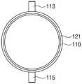
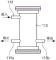
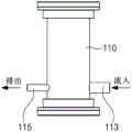
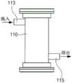
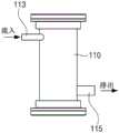
参照图1至图3,本发明的一实施例的流体处理模组100包括在流体向其内部移动的排管110和向所述排管110的流体提供光的光源模组130。排管110沿一方向延伸,并具有两端部开口的形状。排管110可以包括沿长度方向延伸的主体110c以及分别沿所述主体110c的长度方向配置的第一端部110a和第二端部110b。主体110c具有一定的直径且具有内部中空的管形状。第一端部110a和第二端部110b与主体110c的两侧连接,可以具有与主体110c相同的直径或者比主体110c更大的直径。排管110提供供流体在其内部移动并用于处理流体的内部空间、即通道。以下,将排管110延伸的方向称为排管110的延伸方向或者排管110的长度方向。1 to 3 , a
在本发明的一实施例中,排管110大致上呈圆柱形。该情况下,与圆柱的长度方向交叉的截面为原形。但是,排管110的截面形状不限于此,可以由多种形状,例如椭圆、如四边形的多边形、半圆形等构成。In an embodiment of the present invention, the
排管110可以使用反射率高的材质及/或热传导率高的金属形成。例如,排管110可以由不锈钢、铝、氧化镁之类的反射率高的材质形成,或者由不锈钢、铝、银、金、铜、它们的合金之类的热传导率高的材质形成。当为热传导率高的金属时,可以向外部有效排出可能在排管110发生的热。The
但是,排管110的材料不限于此,当光源模组130设置于排管110的外部时,排管110的至少一部分可以由使光透过的材料构成,以使得从光源模组130射出的光到达至排管110内部的流体。作为使所述光透过的材料,可以举出多种高分子树脂、石英、玻璃等。例如,排管110整体由透明的材质构成,或者与光源130相邻的部分由透明的材质构成,从而使来自光源模组130的光到达至流体。However, the material of the
排管110具有供流体流入的流入口113以及排出经处理的流体的排出口115。流入口113及/或排出口115可以设置在排管110的主体110c、第一端部110a以及第二端部110b中的至少某一区域。The
在本发明的一实施例中,如图1以及图2所示,流入口113与排管110连接。连接流入口113的方向可以与排管110的延伸方向不同。在本发明的一实施例中,流入口113的连接方向可以与排管110的延伸方向倾斜或者垂直,由此流体沿着与排管110倾斜或者垂直的方向流入之后,可以沿着排管110的延伸方向移动。通过流入口113向排管110流入的流体为在排管110中需要处理的流体,例如需要进行杀菌、净化、除臭处理的对象物。In an embodiment of the present invention, as shown in FIG. 1 and FIG. 2 , the
排出口115可以设置在与流入口113隔开的位置,并与排管110连接。在本发明的一实施例中,排出口115的连接方向可以与排管110的延伸方向倾斜或者垂直,由此流体可以沿着排管110的延伸方向移动后,朝与排管110倾斜或者垂直的方向排出。通过排出口115从排管110排出的流体为已经在排管110进行处理的流体,例如进行杀菌、净化、除臭处理的对象物。The
在本发明的一实施例中,从与排管110的长度方向垂直的方向观察时,流入口113可以配置在排管110的两端部中的至少某一侧,排出口115也可以配置在排管110的两端部中的至少某一侧。换而言之,在本发明的一实施例中,若将沿着排管110的长度方向的两端部称为第一端部110a以及第二端部110b,则流入口113和排出口115可以分别设置在第一端部110a和第二端部110b中的某一端部侧,或者设置在第一端部110a和第二端部110b的两侧。例如,如图所示,可以在第一端部110a侧设置流入口113,在第二端部110b侧设置排出口115。或者,还可以在第二端部110b侧设置流入口113,在第一端部110a侧设置排出口115。但是,流入口113和排出口115的设置位置不限于此,例如,流入口113及/或排出口115除了设置在两端部之外,还可以设置在排管110的中央部。In an embodiment of the present invention, when viewed from a direction perpendicular to the longitudinal direction of the
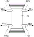
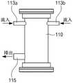
在本发明的一实施例中,沿着排管110的长度方向观察时,流入口113和排出口115也可以被设置为多种形态。图4a至图4c是在本发明的一实施例的流体处理模组中,以一部分构成要件、尤其是以排管110、流入口113以及排出口115为主示出的图,作为一例示出了流入口113和排出口115分别为一个的情况。在图4a至图4c中未说明的符号121是第一反射器。In an embodiment of the present invention, the
首先,参照图4a,从与排管110的延伸方向垂直的截面观察时,流入口113和排出口115可以将排管110的中心位于中间沿彼此相面对的方向与排管110连接。即,流入口113和排出口115可以彼此将排管110的中心位于中间配置在对称的位置。但是,流入口113和排出口115无需以排管110的中心为基准完全对称。参照图4b,以排管110的中心为基准观察时,流入口113和排出口115彼此可以在相同的一侧与排管110连接。该情况下,如图所示,流入口113和排出口115可以以与排管110的一部分隔开的形态形成。即,当沿着排管110的延伸方向划线时,流入口113和排出口115可以设置在相同的线上,但也可以不在相同的线上。但是,不限于此,也可以以彼此重叠的形态设置。参照图4c,流入口113和排出口115可以与排管110连接为呈彼此垂直的角度。First, referring to FIG. 4a , the
这种流入口113和排出口115的位置可以根据采用流体处理模组的装置而不同,尤其,可以根据各个装置所要求的流体的处理量或者杀菌程度,设置为多种形态。The positions of the
在本附图中,示出流入口113和排出口115分别为一个,其是为了说明流入口113和排出口115的位置关系。因此,当流入口113以及排出口115中的至少一个设置为多个时,多个流入口113或者排出口115可以单独设置在其它位置。例如,从排管110的延伸方向观察时,如图所示,当流入口113设置为两个、即第一流入口113a和第二流入口113b时,也可以是第一流入口113a设置在与排放排出口115相对的一侧,第二流入口113b设置在与排出口115相同的一侧。In this drawing, the
再次参照图1至图3,在本发明的一实施例中,流入口113和排出口115的截面可以具有圆形或者椭圆形,但是不限于此,可以设置为多种形状,例如多边形。其中,流入口113和排出口115的截面可以是沿着与流入口113延伸的方向或者与形成流路的方向交叉的方向上的截面。1 to 3 again, in an embodiment of the present invention, the cross-sections of the
虽未图示,在流入口113及/或排出口115可以进一步设置单独的排管。单独的排管可以通过喷嘴与流入口113和排出口115连接。喷嘴可以通过多种方式与流入口113及/或排出口115结合,例如可以是螺栓结合。Although not shown, a separate exhaust pipe may be further provided at the
在本发明的一实施例中,通过流入口113提供的流体的量或者速度以及通过排出口115排出的流体的量或者速度是通过流入口113和排出口115的数量以及直径能够控制。为此,在本发明的一实施例中,流入口113和排出口115的直径可以设置为相同,也可以设置为彼此不相同。在本发明的一实施例中,当流入口113的直径与排出口115的直径相同时,流体处理效率也佳,尤其是,当流入口113的直径比排出口115的直径更大时,流体处理效率可以更高。In one embodiment of the present invention, the amount or velocity of fluid provided through
另外,在本发明的一实施例中,流入口113和排出口115中的至少一个可以设置为多个。例如,可以是流入口113设置为多个而排出口115设置为一个,或者可以是流入口113设置为一个而排出口115设置为多个,或者可以是流入口113和排出口115均设置为多个。当流入口113和排出口115设置为多个时,流入口113和排出口115可以设置成一对一对应的数量。尤其,根据本发明的一实施例,当形成为流入口113为两个且排出口为一个时,能够提高流体处理效率。In addition, in an embodiment of the present invention, at least one of the
图5a至图5c作为本发明的一实施例的流体处理模组的侧视图,是以排管、流入口以及排出口为主示出的图。FIGS. 5 a to 5 c are side views of a fluid processing module according to an embodiment of the present invention, and are diagrams mainly showing the exhaust pipe, the inflow port, and the exhaust port.
根据本发明的一实施例,如图5a至图5c所示,流入口和排出口可以设置为多种数量。例如,如图5a所示,可以具有多个流入口(即,第一流入口113a和第二流入口113b)和一个排出口115,如图5b所示,可以具有一个流入口113和多个排出口(即,第一排出口115a和第二排出口115b),或者如图5c所示,也可以具有多个流入口(即,第一流入口113a和第二流入口113b)和多个排出口(即,第一排出口115a和第二排出口115b)。According to an embodiment of the present invention, as shown in FIGS. 5 a to 5 c , the inflow ports and the discharge ports may be provided in various numbers. For example, as shown in FIG. 5a, there may be multiple inflow ports (ie,
在本实施例中,举出设置有多个流入口和排出口为两个的情况进行了说明,但是不限于此,还可以形成为更多的数量。In this embodiment, the case where a plurality of inflow ports and two discharge ports are provided has been described, but the present invention is not limited to this, and may be formed in a larger number.
再次参照图1至图3,当流入口113设置为两个时,在本发明的一实施例中,当从与排管110的延伸方向垂直的方向观察时,可以是第一流入口113a以及第二流入口113b设置在第二端部110b侧,排出口115设置在第一端部110a侧,当从排管110的延伸方向观察时,可以是第一流入口113a将排管110的中心位于中间设置在与排出口115彼此相对的一侧,第二流入口113b可以以排管110的中心为基准与排出口115设置在同一侧。Referring again to FIGS. 1 to 3 , when two
在后面说明根据流入口113和排出口115的数量以及直径的流体处理效果。The fluid treatment effect according to the number and diameter of the
光源模组130向流体提供适合处理流体的光。光源模组130设置在与流体相邻的多个位置,从而射出处理(例如,杀菌、净化、除臭处理)流体的光。The
光源模组130用于射出光,可以设置在排管110的第一端部110a以及第二端部110b中的至少一侧。在本实施例中,作为一例示出在第一端部110a和第二端部110b均设置光源模组130。但是,光源模组130的位置不限于此,还可以仅在排管110的长度方向的两端部中的一侧设置光源模组130。作为示例,与本实施例中的光源模组130有关的附图应以向排管110内提供光为重点进行解释,光源模组130的位置不限于此。与如图所示不同,光源模组130也可以安装在排管110之外,光源模组130的位置不限于此。The
光源模组130可以包括基板131和安装在基板131上的发光元件133。基板131可以形成为多种形态,例如,可以形成为具有与排管110的直径对应的直径的圆板形态。在基板131上可以沿着一定方向排列有多个发光元件133。在基板131可以形成有用于引出配线的引出口,所述配线用于向发光元件133供应电源。The
当光源模组130包括多个发光元件133时,各个发光元件133可以射出相同波段的光,或者可以射出不同波段的光。例如,在一实施例中,各个发光元件133均可以射出相同或者相似的紫外线波段的光。在其它一实施例中,一部分发光元件133可以射出紫外线波段中的一部分,剩余的发光元件133可以射出紫外线波段中其它波段的一部分。When the
当发光元件133具有不同波段时,发光元件133可以以多种顺序排列。例如,射出第一波段的光的发光元件133和射出与第一波段不同的第二波段的光的发光元件133可以彼此交替排列。When the
光源模组130射出的光可以具有多种波段。来自光源模组130的光可以是可见光波段、红外线波段或者除此之外的波段的光。在本发明的一实施例中,从光源模组130射出的光可以根据流体的种类、所要处理的对象(例如,细菌或者菌等)等具有多种波段,尤其,当对流体进行杀菌时,可以具有杀菌波段。例如,光源模组130可以射出紫外线波段的光。在本发明的一实施例中,光源模组130可以射出作为能够杀灭微生物等的波段的约100nm至约420nm波段的光。光源模组130在本发明的一实施例中可以射出约100nm至约280nm波段的光,在其它实施例中可以射出约180nm至约280nm波段的光,在又一其它实施例中可以射出约250nm至约260nm波段的光。所述波段的紫外线具有强的杀菌力,例如,当以每1cm2 100μW的强度照射紫外线时,可以杀灭约99%的大肠杆菌、白喉杆菌、志贺氏杆菌等细菌。另外,所述波段的紫外线可以杀灭引起食物中毒的细菌,可以杀灭引起食物中毒的病原性大肠杆菌、金黄色葡萄球菌(Staphylococcus aureus)、韦大夫雷登沙门氏菌(Salmonell aWeltevreden)、鼠伤寒沙门氏菌(S.Typhumurium)、粪肠球菌(Ent erococcus faecalis)、蜡样芽胞杆菌(Bacillus cereus)、绿脓杆菌(Pse udomonas aeruginosa)、副溶血弧菌(Vibrio parahaemolyticus)、李斯特菌(Listeria monocytogenes)、小肠结肠炎耶尔森氏菌(Yersinia ente rocolitica)、产气荚膜梭菌(Clostridium perfringens)、肉毒杆菌(Clos tridium botulinum)、空肠弯曲杆菌(Campylobacter jejuni)或者阪崎肠杆菌(Enterobacter sakazakii)等细菌。The light emitted by the
在本发明的一实施例中,光源模组130射出的光可以具有多种波段,光源模组130的至少一部分可以包括在从光源模组130射出的光下发生触媒反应的材料。例如,在本发明的排管110的内周面及/或外周面的全部或者一部分上可以设置有由光触媒材料构成的光触媒层。作为设置有光触媒层的区域,只要是能够使光从光源模组130到达的区域,就不作特别限定。In an embodiment of the present invention, the light emitted by the
光触媒是通过经照射的光引起触媒反应的材料。光触媒可以根据构成光触媒的材料而在多种波段的光下引起反应。在本发明的一实施例中,可以使用在多种波段的光中对紫外线波段的光引起光触媒反应的材料,对此进行说明。但是,光触媒的种类不限于此,可以根据从光源射出的光而使用具有相同或者相似机理的其它光触媒。A photocatalyst is a material that causes a catalytic reaction by irradiated light. The photocatalyst can cause a reaction under light of various wavelength bands depending on the material constituting the photocatalyst. In an embodiment of the present invention, a material that causes a photocatalytic reaction to light in an ultraviolet wavelength band among light in various wavelength bands will be described. However, the type of photocatalyst is not limited to this, and other photocatalysts having the same or similar mechanism may be used depending on the light emitted from the light source.
光触媒被紫外线激活而引起化学反应,从而通过氧化还原反应分解与光触媒接触的流体内的各种污染物质、细菌等。The photocatalyst is activated by ultraviolet rays to cause a chemical reaction, thereby decomposing various pollutants, bacteria, etc. in the fluid in contact with the photocatalyst through a redox reaction.
虽未图示,本发明的一实施例的流体处理模组100可以进一步包括与光源模组130连接的驱动电路以及连接驱动电路和光源模组130的配线部。驱动电路向至少一个光源模组130供应电源。例如,驱动电路设置在具有两个光源模组130的流体处理模组100,从而可以向两个光源模组130分别单独提供电源。由此,能够进行将两个光源模组130全部开启或者关断或者开启一个且关断剩余一个等选择性驱动。Although not shown, the
在光源模组130和排管110内的流体处理空间之间可以进一步设置有透过窗137,该透过窗137使来自光源模组130的光向排管110内透过。A
透过窗137用于保护基板131和光源,可以由透明材料构成。透过窗137可以由多种材料构成,其材料并不作限制。例如,透过窗137可以由石英或者高分子有机材料构成。其中,当为高分子玻璃材料时,由于根据单体的种类、成形方法、条件而吸收/透过的波长不同,因此,可以考虑从光源射出的波长来选择。例如,聚甲基丙烯酸甲酯(poly(methylmethacrylate);PMMA)、聚乙烯醇(polyvinylalcohol;PVA)、聚丙烯(polypropylene;PP)、低密度聚乙烯(polyethylene;PE)之类的有机高分子几乎不吸收紫外线,而聚酯(polyester)之类的有机高分子可以吸收紫外线。The
在本实施例中,基板131和透过窗137可以设置为与排管110对应的形状和大小。In the present embodiment, the
在光源模组130的外侧面设置有用于向外部排出从光源模组130产生的热的散热板。在本发明的一实施例中,当光源模组130设置在排管110的两端部时,在两个光源模组130的外侧分别设置有第一散热板140a和第二散热板140b。A heat dissipation plate for discharging heat generated from the
第一散热板140a以及第二散热板140b由热传导率比光源模组130的基板131更高的材质构成,起到通过基板131接收从光源模组130、尤其从发光元件133产生的热并向外部排出的作用。为此,第一散热板140a以及第二散热板140b分别与光源模组130的基板131的背面直接接触。The first
作为热传导率比光源模组130的基板131高的材质,可以有多种,当基板131为金属基板131时,第一散热板140a以及第二散热板140b各自可以从热传导率比构成基板131的金属更高的材质中进行选择。例如,当基板131由不锈钢构成时,第一散热板140a以及第二散热板140b可以由热传导率比不锈钢高的金属、例如铝构成。第一散热板140a以及第二散热板140b的材料可以在具有比基板131更高的热传导率的范围内进行多种选择,而且不限于此。There may be various materials with higher thermal conductivity than the
在本发明的一实施例中,第一散热板140a以及第二散热板140b为了有效排出来自基板131的热,可以具有比基板131更宽的面积。基板131可以设置在排管110内并具有与排管110的直径对应的直径,而第一散热板140a以及第二散热板140b可以具有比基板131的直径更大的直径。另外,第一散热板140a以及第二散热板140b各自可以具有比排管110的主体110c的直径更大的直径。第一散热板140a以及第二散热板140b可以设置在作为排管110的两端部侧的第一端部110a以及第二端部110b,因此能够制成从排管110的两端部凸出的形态,容易形成为具有更宽的直径。In an embodiment of the present invention, the first
在本发明的一实施例中,通过设置第一散热板140a以及第二散热板140b,能够向外部容易排出从光源发出的热。其结果,防止因在光源中产生的热导致的光源的劣化,由此,流体处理模组100的可靠度变高的同时,具有稳定的杀菌效果。In an embodiment of the present invention, by providing the first
在本发明的一实施例中,在流体处理模组100中除了设置基板131和发光元件133之外,还可以设置用于提高流体处理效率的反射器120,所述反射器120通过反射光,以使来自发光元件133的光能够进入到排管110内。In an embodiment of the present invention, in addition to the
反射器120具有比排管110更高的反射率。例如,当排管110由不锈钢之类的材料构成时,反射器120由具有比不锈钢更高的反射率的材料构成。在本发明的一实施例中,通过利用反射率比排管110高的材料,在排管110内设置反射器120,从而能够提高穿过排管110内的光的反射率。当光的反射率变高时,光在排管110内有效地反复进行反射,提高流体处理效率。The
反射器120可以由反射来自光源模组130的光的材料构成。在一实施例中,反射器120可以由反射80%以上的来自光源模组130的光的材料构成,在其它实施例中,反射器120可以由反射90%以上的来自光源模组130的光的材料构成,在其它另一实施例中,反射器120可以由反射99%以上的来自光源模组130的光的材料构成。The
反射器120可以由反射性高的材料构成,以使从发光元件133芯片射出的光的光提取效率最大化。例如,反射器120可以由具有用于提高在其表面上的光的反射以及散射的粗糙度的材料构成,或者反射器120可以由具有多孔性表面结构的材料构成。作为具有表面粗糙度的多孔性材料,可以有多样,在本发明的一实施例中,可以举出高分子树脂,作为一例,可以举出如PTFE。但是,构成反射器120的材料不限于此,只要能够确保充分的反射率,则还可以使用其它材料。例如,反射器120可以由铝及/或铝合金构成。但是,除了铝及/或铝合金之外,还可以由反射性高的材料、例如银、金、锡、铜、铬、镍、钼、钛等多种金属及/或包含其的合金构成。The
反射器120可以包括设置在排管110内的第一反射器121和与光源模组130相邻设置的第二反射器123。第一反射器121和第二反射器123可以由相同的材料形成,也可以由不同的材料形成。例如,第一反射器121和第二反射器123均可以由PTFE(聚四氟乙烯;Polytetrafluoroethylene)形成,或者还可以是第一反射器121由PTFE形成,第二反射器123由铝合金形成。The
第一反射器121覆盖排管110的内侧面。当排管110形成为圆筒形时,第一反射器121可以设置为围绕整个排管110的圆筒形内壁的形态。其中,在相当于流入口113和排出口115的部分的内壁可以设置有第一反射器121,也可以不设置。在本发明的一实施例中,在排管110内壁中,光到达的区域尽量设置有第一反射器121,从而可以使排管110内壁几乎不露出。The
第二反射器123沿着安装有发光元件133的区域的外围设置在基板131上。第二反射器123用于反射光,以使从发光元件133射出的光进入到排管110内的各个区域,为此,第二反射器123具有暴露发光元件133的安装区域的开口,并以上下部贯通的环形设置在基板131上。The
本发明的一实施例的第二反射器123可以具有与开口相对的内侧面、与外部相对的外侧面以及与基板131的顶面相接触的底面。内侧面的至少一部分相对于基板131的顶面倾斜设置。由此,第二反射器123的开口的宽度从基板131的顶面越往上部方向逐渐变大。换而言之,第二反射器123的内径从基板131顶面越往上部方向逐渐变大。从截面观察第二反射器123时,倾斜的边可以为直线或者曲线,倾斜度考虑到发光元件133的数量、发光元件133的指向角、来自发光元件133的光量等,可以设定为多种角度。The
在本发明的一实施例的流体处理模组100中,可以设置一个以上的密封部件151a、151b,所述密封部件151a、151b用于将排管110紧密地紧固在第一散热板140a以及第二散热板140b的同时,防止流体向其它区域泄露。In the
在本发明的一实施例中,密封部件151a、151b相邻设置于流体处理空间,例如,可以设置在第一罩盖和排管110的第一端部110a之间以及第二罩盖和排管110的第二端部110b之间。各个密封部件151a、151b可以包括设置在基板131和透过窗137之间以及透过窗137和排管110内的凸台部之间的第一密封部件150a以及第二密封部件150b。第一密封部件150a以及第二密封部件150b分别紧密地紧固排管110与第一罩盖以及第二罩盖的同时,防止第一内部空间的流体通过排管110与第一罩盖以及第二罩盖之间向外部泄漏。例如,通过将流体处理空间从光源模组130进行分离,能够防止光源模组130被流体损坏。密封部件151a、151b可以设置为单个或者多个。In one embodiment of the present invention, the sealing
当第一罩盖以及第二罩盖与排管110紧固时,密封部件151a、151b具有闭合图形(closed figure)形状,以使紧密地紧固排管110的内部和外部,并分开密封两个区域。例如,第一密封部件150a以及第二密封部件150b可以具有O型环(o-ring)形状。When the first cover and the second cover are fastened to the
所述密封部件151a、151b可以由具有柔性的弹性材料构成。当密封部件151a、151b由弹性材料构成时,当排管110与第一散热板140a以及第二散热板140b彼此紧固时,挤压紧固于排管110,从而保持紧密的紧固结构。The sealing
作为构成密封部件151a、151b的弹性材料,可以举出硅树脂,但是不限于此,可以由其它材料构成。例如,作为弹性材料,可以使用天然或者合成橡胶,可以使用除此之外的其它高分子有机弹性材料。As the elastic material constituting the sealing
在本发明的一实施例中,第一散热板140a以及第二散热板140b各自可以作为分别封装排管110的第一端部110a以及第二端部110b的第一罩盖以及第二罩盖来使用。由此,在本发明的一实施例中,第一散热板140a以及第二散热板140b可以具有与排管110结合的紧固部。In an embodiment of the present invention, the first
紧固部可以形成为多种形态。例如,第一散热板140a以及第二散热板140b作为紧固部可以具有插入部,所述插入部具有与排管110的内径对应的直径,并插入于排管110的端部进行紧固,从而能够封装排管110。The fastening portion may be formed in various forms. For example, the
在本发明的一实施例中,第一散热板140a设置在排管110的第一端部110a并与排管110紧固。第一散热板140a形成有具有彼此不同外径的阶梯部,从而可以插入紧固于排管110。例如,第一散热板140a设置为与排管110的第一端部110a相面对的部分具有与排管110的内径对应的外径。In an embodiment of the present invention, the first
在本发明的一实施例中,在排管110和第一散热板140a可以设置有用于结合排管110和第一散热板140a的紧固部件。例如,在排管110和第一散热板140a设置有紧固孔143a,通过将紧固螺栓143b与排管110和第一散热板140a的紧固孔143a结合,从而可以结合排管110和第一散热板140a。In an embodiment of the present invention, the
第二散热板140b设置在排管110的第二端部110b并与排管110紧固。在第二散热板140b也形成有具有彼此不同外径的阶梯部,从而可以通过与第一散热板140a相同的方式,插入紧固于排管110。The second
与此相同地,在排管110和第二散热板140b可以设置有用于结合排管110和第二散热板140b的紧固部件。例如,在排管110和第二散热板140b设置有紧固孔143a,通过将紧固螺栓143b与排管110和第二散热板140b的紧固孔143a结合,从而可以结合排管110和第二散热板140b。Similarly, the
在本发明的一实施例中,第一散热板140a以及第二散热板140b不仅作为用于散发从光源模组130产生的热的散热部件来使用,还作为用于封装排管110的封装工具、即第一罩盖以及第二罩盖来使用。但是,这相当于一实施例,作为与第一散热板140a以及第二散热板140b单独的构成要件,还可以进一步将用于封装排管110的封装部件作为单独的构成要件来提供。该情况下,单独的封装部件也可以由热传导率高的物质构成,以能够更好地散发来自第一散热板140a以及第二散热板140b的热。In an embodiment of the present invention, the first
在具有上述结构的流体处理模组中,流体沿着排管的延伸方向移动,从而暴露在来自光源模组的光,由此对流体执行杀菌等处理。本发明的一实施例的流体处理模组通过控制流入口和排出口的数量以及直径,并通过反射器提高光效率,从而显著提升流体处理效率。另外,通过使用散热板,确保光源模组的可靠性。In the fluid treatment module having the above-described structure, the fluid moves along the extending direction of the exhaust pipe to be exposed to light from the light source module, thereby performing treatment such as sterilization on the fluid. The fluid treatment module of an embodiment of the present invention significantly improves the fluid treatment efficiency by controlling the number and diameter of the inflow ports and the discharge ports, and improving the light efficiency through the reflector. In addition, by using a heat sink, the reliability of the light source module is ensured.
用于实施发明的方式means for carrying out the invention
本发明的一实施例的流体处理模组在不脱离本发明的概念的范围内可以变形为多种形态。The fluid processing module of an embodiment of the present invention can be deformed into various forms without departing from the concept of the present invention.
图6是示出本发明的一实施例的流体处理模组的分解立体图,图7是示出本申请的一实施例的流体处理模组的立体纵截面图。为了避免重复说明,在以下的实施例中,以与上述实施例不同之处为主进行说明。6 is an exploded perspective view showing a fluid treatment module according to an embodiment of the present invention, and FIG. 7 is a perspective longitudinal sectional view showing the fluid treatment module according to an embodiment of the present application. In order to avoid repeated descriptions, in the following embodiments, the differences from the above-described embodiments will be mainly described.
参照图6以及图7,本发明的一实施例的流体处理模组100包括流体在其内部移动的排管110和向所述排管110的流体提供光的光源模组130。排管110沿一方向延伸,并具有一端部堵住且一端部开口的形状。当排管110具有沿长度方向延伸的主体110c以及分别沿所述主体110c的长度方向配置的第一端部110a和第二端部110b时,第一端部110a具有没有入口的封闭形状,第二端部110b具有开口的形状。6 and 7 , a
在排管110形成有供流体流入的流入口113以及排出经处理的流体的排出口115。在本实施例中,流入口113可以设置在开口的端部、即第二端部110b侧,排出口115可以设置在封闭的端部、即第一端部110a侧。The
在本实施例中,流入口113可以设置为多个,例如第一流入口113a和第二流入口113b。在本实施例中,第一流入口113a和第二流入口113b可以均设置在第二端部110b侧。In this embodiment, a plurality of
在本发明的一实施例中,与上述的其它实施例相同,通过流入口113提供的流体的量或者速度以及通过排出口115排出的流体的量或者速度是可以通过流入口113和排出口115的数量以及直径进行控制。In an embodiment of the present invention, the same as the other embodiments described above, the amount or speed of the fluid provided through the
光源模组130向流体提供用于处理流体所适合的光,在本实施例中,可以设置在排管110的第一端部110a以及第二端部110b中的第二端部110b侧。在没有开口的第一端部110a侧不设置光源模组130。光源模组130可以包括基板131和安装在基板131上的发光元件133。The
在光源模组130和排管110内的流体处理空间之间可以进一步设置用于使来自光源模组130的光透过的透过窗137。A
在光源模组130的端部中开口的一侧设置有用于向外部排出从光源模组130产生的热的散热板140。当光源模组130设置在排管110的第二端部110b时,在第二端部110b侧设置有散热板140。A
散热板140由热传导率比光源模组130的基板131更高的材质构成,起到通过基板131接收从光源模组130、尤其发光元件133产生的热并向外部排出的作用。为此,散热板140与光源模组130的基板131的背面直接接触。The
在本发明的一实施例中,散热板140为了有效排出来自基板131的热,可以具有比基板131更宽的面积。基板131可以设置在排管110内并具有与排管110的直径对应的直径,散热板140可以具有比基板131的直径更大的直径。另外,散热板140各自可以具有比排管110的主体110c的直径更大的直径。散热板140可以设置在排管110的第二端部110b,因此能够制成从排管110的第二端部110b的外径向外侧方向凸出的形态,并容易形成为具有更宽的直径。In an embodiment of the present invention, the
进一步地,散热板140可以包括从其表面向外侧方向凸出的突起141,使得容易将热最大限度地向外部散发。突起141可以设置为多个,通过设置多个突起141,散热板140的表面积相比不设置突起141时显著增加。当散热板140的表面积增加时,与外部空气的接触面积变宽,从而能够向空气有效散发散热板140的热。在本发明的一实施例中,突起141可以具有向一方向长长地延伸的板形状,并可以彼此隔开。但是,突起141的形状不限于此,只要是能够加宽表面积,则其形状不受特别限制。Further, the
在本实施例中,包含突起141的散热板140还可以形成为整体不分离的一体。当散热板140形成为整体不分离的一体时,与不是这样的情况相比,热传递可以稍微更加容易。In this embodiment, the
在本发明的一实施例中,通过设置散热板140,可以向外部容易排出从光源产生的热。其结果,防止因在光源中产生的热导致的光源的劣化,由此,流体处理模组100的可靠度变高的同时,具有稳定的杀菌效果。In an embodiment of the present invention, the heat generated from the light source can be easily radiated to the outside by providing the
在本实施例中,主体110c中第一端部110a为封闭的结构,通过一侧流入流体,通过另一侧排出流体,因此,在主体110c内因被封闭的部分而容易形成涡流。流体因这样的涡流而停留在主体110c内的时间增加。由此,暴露在来自光源模组130的光的时间充分变长,最终也会提高流体的处理效果。In this embodiment, the
随着因涡流的形成而流体停留在主体110c内的时间增加,光效率会增加。即,由于向流体照射充分量的光,因此,在本实施例中,仅在一侧设置光源模组130,也能够获得充分的流体处理效果。另外,由于向流体照射充分量的光,因此,主体110c的长度也可以设置为比上述实施例更短的长度。其中,当主体110c的长度设置为短时,在主体110c内也能够更容易产生涡流。The optical efficiency increases as the time that the fluid resides within the
进一步地,由于光效率的增加而与上述实施例不同,还可以省略反射光而使光向排管110内进入的反射器的一部分、例如围绕排管110的墙壁的反射器。在本实施例中,反射器120中可以省略设置在排管110内的第一反射器121(参照图2以及图3),仅提供与光源模组130相邻设置的第二反射器123。其中,第二反射器123是沿着安装有发光元件133的区域的外围设置在基板131上,具有使发光元件133的安装区域暴露的开口且以上下部贯通的环状设置在基板131上。Further, different from the above-described embodiments due to the increase in light efficiency, a part of the reflector that reflects the light and allows the light to enter into the
在本发明的一实施例的流体处理模组100可以设置有密封部件,所述密封部件将排管110紧密地紧固在散热板的同时,防止流体泄漏到其它区域。In one embodiment of the present invention, the
在本发明的一实施例中,在图2以及图3中示出的上述实施例中,密封部件设置为两个,但是在本实施例中,可以设置为一个。在本实施例中,密封部件150可以与流体处理空间相邻设置,并提供为以“ㄈ”字形围绕透过窗137的端部的形态。In an embodiment of the present invention, in the above-mentioned embodiment shown in FIG. 2 and FIG. 3 , two sealing members are provided, but in this embodiment, one sealing member may be provided. In the present embodiment, the sealing
在本发明的一实施例中,散热板140各自可以作为封装排管110的第二端部110b的罩盖来使用。由此,在本发明的一实施例中,散热板140可以具有与排管110结合的紧固部。In an embodiment of the present invention, each of the
紧固部可以形成为多种形态。例如,散热板140作为紧固部可以具有插入部,所述插入部具有与排管110的内径对应的直径并插入于排管110的端部而紧固,从而能够封装排管110。The fastening portion may be formed in various forms. For example, the
在本发明的一实施例中,散热板140设置在排管110的第二端部110b而与排管110紧固。散热板140形成有具有彼此不同外径的阶梯部,从而可以插入紧固于排管110。例如,散热板140设置为与排管110的第二端部110b相面对的部分具有与排管110的内径对应的外径。In an embodiment of the present invention, the
在本发明的一实施例中,在排管110和散热板140可以分别设置有用于结合排管110和散热板140的紧固部件。In an embodiment of the present invention, the
在本发明的一实施例中,散热板140不仅作为用于散发从光源模组130产生的热的散热部件来使用,还作为用于封装排管110的封装工具、即罩盖来使用。但是,这相当于一实施例,作为与散热板140单独的构成要件,还可以进一步将用于封装排管110的封装部件作为单独的构成要件。该情况下,单独的封装部件也可以由热传导率高的物质构成,以能够更好地散发来自散热板140的热。In an embodiment of the present invention, the
具有上述结构的流体处理模组通过主体的长度变短,能够减小整体大小。另外,由于内部涡流的增加而流体停留在主体内的时间变长,充分确保杀菌效果,由此能够减少光源模组的数量的同时,还能够减少整个发光元件的数量。由此,使得光源模组以及光源模组内的发光元件的数量减少,减少将主体的两端部全部进行防水处理或者组装散热板等的制造工艺以及费用。In the fluid processing module having the above-mentioned structure, the length of the main body can be shortened, and the overall size can be reduced. In addition, due to the increase of the internal eddy current, the fluid stays in the main body for a long time, and the sterilization effect is fully ensured, thereby reducing the number of light source modules and the entire number of light-emitting elements. This reduces the number of light source modules and light-emitting elements in the light source module, and reduces the manufacturing process and cost of waterproofing both ends of the main body or assembling heat sinks.
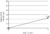
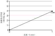
图8a以及图8b是示出根据反射器的有无的流体处理效果的图表,图8c是示出图8a以及图8b的实验中使用的流体处理模组的侧视图。在图8a中,比较例是完全没有设置反射器,即没有设置第一反射器以及第二反射器,实施例1是仅设置第二反射器,实施例2是设置有第一反射器以及第二反射器。在图8b中,实施例3是仅设置第一反射器,实施例4是均设置有第一反射器以及第二反射器。8a and 8b are graphs showing the effect of fluid treatment according to the presence or absence of a reflector, and FIG. 8c is a side view showing the fluid treatment module used in the experiments of FIGS. 8a and 8b. In Fig. 8a, the comparative example is not provided with a reflector at all, that is, the first reflector and the second reflector are not provided, the
在图8a以及图8b中,为了确认根据反射器的有无的流体的处理效果,除了反射器之外的所有条件设定为相同,然后通过改变所要处理的流体的流量执行了实验。流体为水,作为细菌使用了大肠杆菌(E.coli)。根据流体处理的细菌的非活性度是用对数尺度(logCFU/mL)进行了表示,值越大,显示更高的杀菌处理能力(例如,3log CFU/mL表示99.9%的细菌非活性度)。使用的流体处理模组中,流入口和排出口在相同端部侧分别彼此相对地设置有一个,流入口的直径比排出口的直径大两倍。In FIGS. 8 a and 8 b , in order to confirm the treatment effect of the fluid according to the presence or absence of the reflector, all conditions except for the reflector were set to be the same, and then experiments were performed by changing the flow rate of the fluid to be treated. The fluid was water, and E. coli was used as bacteria. Bacterial inactivity according to fluid treatment is expressed on a logarithmic scale (logCFU/mL), with larger values indicating higher bactericidal treatment capacity (eg, 3 log CFU/mL represents 99.9% bacterial inactivity) . In the fluid processing module used, one inflow port and one discharge port were provided on the same end side to face each other, and the diameter of the inflow port was twice larger than the diameter of the discharge port.
参照图8a,与比较例相比,实施例1以及实施例2显示显著高的流体处理效率,即杀菌效率。例如,当处理1LPM(每分钟公升,liter per minute)的流体时,关于杀菌效率,比较例为1.551(log CFU/mL),而实施例1以及实施例2分别为2.767(log CFU/mL)以及3.216(log CF U/mL)。进一步地,当为2LPM时,比较例仅是1.080(log CFU/mL),而实施例1以及实施例2为2.078(log CFU/mL)以及3.732(log CFU/mL)。其中,能够确认到,尤其是当为安装有第一反射器以及第二反射器的实施例2时,与仅使用第二反射器的实施例1相比显示显著高的杀菌效率。Referring to Figure 8a, compared to the comparative example, Example 1 and Example 2 showed significantly higher fluid treatment efficiency, ie, sterilization efficiency. For example, when dealing with a fluid of 1 LPM (liter per minute), the sterilization efficiency is 1.551 (log CFU/mL) for the comparative example, and 2.767 (log CFU/mL) for Example 1 and Example 2, respectively and 3.216 (log CF U/mL). Further, when it is 2LPM, the comparative example is only 1.080 (log CFU/mL), while Example 1 and Example 2 are 2.078 (log CFU/mL) and 3.732 (log CFU/mL). Among them, it was confirmed that, in particular, Example 2 in which the first reflector and the second reflector were attached showed significantly higher sterilization efficiency than Example 1 in which only the second reflector was used.
参照图8b,实施例3以及实施例4显示显著高的流体处理效率,即杀菌效率。例如,当处理1LPM(liter per minute)的流体时,实施例3以及实施例4分别为4.666(log CFU/mL)以及5.413(log CFU/mL)。其中,能够确认到,尤其是当为安装有第一反射器以及第二反射器的实施例4时,与仅使用第一反射器的情况相比显示显著高的杀菌效率。Referring to Figure 8b, Example 3 and Example 4 show significantly high fluid treatment efficiency, ie, sterilization efficiency. For example, when processing a fluid of 1 LPM (liter per minute), Example 3 and Example 4 were 4.666 (log CFU/mL) and 5.413 (log CFU/mL), respectively. Among them, it was confirmed that particularly in Example 4 in which the first reflector and the second reflector were attached, significantly higher sterilization efficiency was exhibited than when only the first reflector was used.
如上所述,本发明的一实施例的流体处理模组中设置有反射器,从而显示显著高的流体处理能力。As described above, the fluid treatment module of one embodiment of the present invention is provided with a reflector, thereby exhibiting a significantly high fluid handling capacity.
在本发明的一实施例的流体处理模组中,流入口和排出口为了控制在排管内移动的流体而可以设置为多种形态,图9a至图9f是示出以多种形态改变流入口和排出口的流体处理模组的图,图10a至图10f是示出分别使用图9a至图9f中示出的流体处理模组时的流体处理效果的图表。In the fluid processing module according to an embodiment of the present invention, the inflow port and the discharge port can be provided in various forms in order to control the fluid moving in the exhaust pipe. Figures 10a to 10f are graphs showing the effects of fluid treatment when using the fluid treatment modules shown in Figures 9a to 9f, respectively.
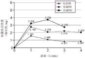
在图9a至图9f以及图10a至图10f中,除了流入口和排出口的配置和直径变化之外的所有条件设置为相同,并将所要处理的流体的流量设定为1LPM执行了实验。尤其,在本实施例中均使用了反射器。流体为水,作为细菌使用了大肠杆菌(E.coli)。根据流体处理的细菌的非活性度是用对数尺度(log CFU/mL)进行了表示,值越大,显示更高的杀菌处理能力(例如,3log CFU/mL表示99.9%的细菌非活性度)。In Figures 9a to 9f and Figures 10a to 10f, all conditions except for configuration and diameter changes of the inflow and discharge ports were set to be the same, and experiments were performed with the flow rate of the fluid to be treated set to 1 LPM. In particular, reflectors are used in all of the present embodiments. The fluid was water, and E. coli was used as bacteria. Bacterial inactivity according to fluid treatment is expressed on a logarithmic scale (log CFU/mL), with higher values indicating higher bactericidal treatment capacity (eg, 3 log CFU/mL represents 99.9% bacterial inactivity ).
首先,通过比较图10a以及图10b,能够确认根据流入口以及排出口的直径的杀菌效率。First, by comparing Fig. 10a and Fig. 10b, the sterilization efficiency according to the diameter of the inflow port and the discharge port can be confirmed.
图10a以及图10b是流入口和排出口分别设置为一个的情况,图10a示出流入口和排出口的直径相同时的杀菌效果,图10b示出排出口的直径设定为比流入口的直径小1/2时的杀菌效果。10a and 10b show the case where one inflow port and one discharge port are provided, respectively. FIG. 10a shows the sterilization effect when the diameters of the inflow port and the discharge port are the same, and FIG. 10b shows that the diameter of the discharge port is set to be larger than that of the inflow port. The bactericidal effect when the diameter is 1/2 smaller.
参照图10a以及图10b,在流入口和排出口分别配置为一个的情况下,当流入口和排出口的直径相同时,在1LPM下显示2.623(log CFU/mL)的细菌非活性度,当流入口和排出口的直径彼此不相同时,在1LPM下显示2.350(log CFU/mL)的细菌非活性度。如上所述,当流入口和排出口分别设置为一个时,与流入口和排出口的直径无关,显示不足3.000(logCFU/mL)的细菌非活性度,根据直径大小的非活性度之间的差异并不大。Referring to FIGS. 10a and 10b , in the case where one inflow port and one discharge port are respectively arranged, when the diameters of the inflow port and the discharge port are the same, the bacterial inactivity of 2.623 (log CFU/mL) is shown at 1 LPM, and when When the diameters of the inflow port and the discharge port were different from each other, bacterial inactivity of 2.350 (log CFU/mL) was shown at 1 LPM. As described above, when the inflow port and the discharge port are each set to one, regardless of the diameters of the inflow port and the discharge port, the bacterial inactivation degree of less than 3.000 (logCFU/mL) is shown, and the difference between the inactivation degree according to the size of the diameter The difference is not huge.
图10c示出流入口设置为两个(即第一流入口以及第二流入口)并排出口设置为一个的情况,示出流入口和排出口的直径相同时的杀菌效果。Fig. 10c shows a case where two inflow ports (ie, a first inflow port and a second inflow port) and one discharge port are provided, and shows the sterilization effect when the diameters of the inflow port and the discharge port are the same.
参照图10c,当流入口配置为两个且流入口和排出口的直径相同时,在1LPM下显示4.147(log CFU/mL)的细菌非活性度。即,能够确认到,当流入口的数量增加时,与流入口和排出口分别设置为一个的情况相比,流体处理效果、即杀菌效果显著增加。Referring to Fig. 10c, when the inflow ports were configured in two and the diameters of the inflow ports and the discharge ports were the same, bacterial inactivity of 4.147 (log CFU/mL) was shown at 1 LPM. That is, it can be confirmed that when the number of inflow ports is increased, the fluid treatment effect, that is, the sterilization effect, is remarkably increased compared with the case where each of the inflow port and the discharge port is provided one.
这是因为随着供流体向排管内流入的流入口的增加,这与不是这样的情况相比,会在排管内产生涡流,从而在保持相同流速的同时,暴露在杀菌光中的频度会增加。当流速减小时,一般是暴露在杀菌光中的频度会增加,但是在本发明中,如上所述,通过控制流入口的数量,能够将流速保持在1LPM的同时,提高杀菌效果。This is because as the inflow of the supply fluid into the drain increases, eddy currents are created in the drain compared to the case where it is not, so that the frequency of exposure to germicidal light will increase while maintaining the same flow rate. Increase. When the flow rate decreases, the frequency of exposure to germicidal light generally increases, but in the present invention, as described above, by controlling the number of inflow ports, the germicidal effect can be improved while the flow rate is maintained at 1 LPM.
在本发明的一实施例中,能够确认到流入口以及排出口的数量相同并直径不同时的杀菌效果,图10d示出流入口和排出口的数量与图10c相同而排出口的直径设定为比流入口的直径小1/2的情况时的杀菌效果,图10e示出流入口和排出口的数量与图10c相同而流入口的直径设定为比排出口的直径小1/2的情况时的杀菌效果。其结果,在排出口的直径设定为比流入口的直径小1/2的图10d的情况下,在1LPM下显示3.888(log CFU/mL)的细菌非活性度,在流入口的直径设定为比排出口的直径小1/2的图10e情况下,在1LPM下显示3.897(log CFU/mL)的细菌非活性度。In an embodiment of the present invention, the sterilization effect can be confirmed when the number of inflow ports and the discharge ports are the same and the diameters are different. Fig. 10d shows that the number of inflow ports and discharge ports is the same as that of Fig. 10c, and the diameter of the discharge port is set For the sterilization effect when the diameter of the inflow port is 1/2 smaller than that of the inflow port, Fig. 10e shows that the number of the inflow port and the discharge port is the same as that of Fig. 10c, and the diameter of the inflow port is set to be 1/2 smaller than the diameter of the discharge port. The bactericidal effect of the situation. As a result, in the case of Fig. 10d in which the diameter of the discharge port was set to be 1/2 smaller than the diameter of the inflow port, the bacterial inactivation degree of 3.888 (log CFU/mL) was shown at 1 LPM, and the diameter of the inflow port was set to 1/2. In the case of Fig. 10e, which was set to be 1/2 smaller than the diameter of the discharge port, the bacterial inactivity was 3.897 (log CFU/mL) at 1 LPM.
根据图10c至图10e,与流入口和排出口的直径之差无关,均显示3(log CFU/mL)的高杀菌力(即,99.9%的细菌非活性度),能够再次确认到,随着流入口的数量的增加,流体处理效率显著增加。进一步地,能够确认到,将流入口和排出口的直径调整为多样时,能够再进一步提高流体处理效率,尤其,如图10c所示,能够确认到,当流入口和排出口的直径相同时,流体处理效率进一步提升。According to FIGS. 10c to 10e, regardless of the difference between the diameters of the inflow port and the discharge port, a high sterilization power of 3 (log CFU/mL) (that is, a bacterial inactivity degree of 99.9%) was shown. As the number of inflow ports increases, the fluid handling efficiency increases significantly. Further, it can be confirmed that when the diameters of the inlet and outlet are adjusted to be various, the fluid processing efficiency can be further improved. In particular, as shown in FIG. 10c, it can be confirmed that when the diameters of the inlet and outlet are the same, , the fluid handling efficiency is further improved.
图10f是与上述实验例不同,将流入口和排出口配置为不同,属于将流入口和排出口形成在相同侧端部的情况。参照图10f,当流入口和排出口形成在相同侧端部时,能够确认到,在1LPM下显示1.268(log CFU/mL)的细菌非活性度,从而杀菌效率极大降低。这是因为由于流入口和排出口形成在相同侧,因此不能充分停留在排管内而向外部排出的流体增加的缘故。Fig. 10f is different from the above-described experimental example, in which the inflow port and the discharge port are arranged differently, and the inflow port and the discharge port are formed at the same side end portion. 10f , when the inflow port and the discharge port were formed on the same side end, it was confirmed that the bacterial inactivity of 1.268 (log CFU/mL) was exhibited at 1 LPM, and the sterilization efficiency was greatly reduced. This is because since the inflow port and the discharge port are formed on the same side, the fluid that is discharged to the outside cannot sufficiently stay in the exhaust pipe and increases.
图11、图12a以及图12b是示出在本发明的一实施例的流体处理模组中,根据在排管内移动的流体的流量的流体的杀菌效率的图表。图11是示出利用图9d中示出的流体处理模组时的流体处理效果(即,杀菌效果)的图表,图12a以及图12b是将利用图9c中示出的流体处理模组时的流体处理效果检测两次来示出的图表。11 , 12 a and 12 b are graphs showing the sterilization efficiency of the fluid according to the flow rate of the fluid moving in the exhaust pipe in the fluid processing module according to the embodiment of the present invention. Fig. 11 is a graph showing the fluid treatment effect (ie, the sterilization effect) when the fluid treatment module shown in Fig. 9d is used, and Figs. 12a and 12b are when the fluid treatment module shown in Fig. 9c is to be used The fluid treatment effect was tested twice to show the graph.
参照图11、图12a以及图12b,在本发明的一实施例的流体处理模组中,即便在排管内移动的流体的流量增加,整体杀菌力的减少非常缓慢。换而言之,图11、图12a以及图12b中,当流体处理速度从1LPM增加到5LPM时,虽然随着流量的增加显示杀菌效率依次减小的效果,但是即便流量相对于初次增加5倍,其杀菌效率的减小量不大而均显示3(log CFU/mL)以上的杀菌效率。由此,当为本发明的一实施例的流体处理模组时,能够确认到,提高流体处理速度时杀菌力也保持高的状态,最终能够杀菌的流体的体积会增加。进一步地,根据本发明的实施例的流体处理模组针对多种速度充分保证杀菌力,因此能够采用的装置的范围广。安装流体处理模组的装置可以有净水器、清洁器、坐浴桶等而多样,而且各个装置所需的流量也不同。如上所述,根据本发明的实施例的流体处理模组,即便是流量不同的装置也可以适用。11, 12a and 12b, in the fluid treatment module of an embodiment of the present invention, even if the flow rate of the fluid moving in the exhaust pipe increases, the overall sterilization power decreases very slowly. In other words, in FIGS. 11 , 12a and 12b , when the fluid treatment speed was increased from 1 LPM to 5 LPM, although the effect of decreasing the sterilization efficiency as the flow rate increased, even if the flow rate increased 5 times compared to the first time. , the reduction of the bactericidal efficiency is not large, and they all show a bactericidal efficiency of more than 3 (log CFU/mL). Thus, in the case of the fluid treatment module according to an embodiment of the present invention, it was confirmed that the sterilizing power remains high even when the fluid treatment speed is increased, and the volume of the fluid that can be sterilized eventually increases. Further, the fluid treatment module according to the embodiment of the present invention sufficiently guarantees the sterilization power for various speeds, and thus can employ a wide range of devices. The devices for installing the fluid treatment module can include water purifiers, cleaners, bidets, etc., and the flow required by each device is also different. As described above, the fluid processing module according to the embodiment of the present invention can be applied even to devices with different flow rates.
图13示出采用本发明的一实施例的流体处理模组的装置,是作为一例示出水处理装置的模式图。FIG. 13 shows an apparatus using the fluid treatment module according to an embodiment of the present invention, and is a schematic diagram showing a water treatment apparatus as an example.
参照图13,本发明的一实施例的水处理装置包括:过滤器61,一次过滤水;储水槽67,储藏通过过滤器61的水;以及流体处理模组100,与储水槽67连接。13 , a water treatment device according to an embodiment of the present invention includes a
过滤器61用于去除供应的水中的杂质。水处理装置可以进一步包括与过滤器61连接的泵(未图示),通过泵可以向过滤器61供应水。过滤器61可以是去除大杂质的过滤器、去除重金属以及细菌等的过滤器等可以设置为多个,若仅通过流体处理模组100对从外部充分完成净化的水进行杀菌,则可以省略过滤器61。The
通过过滤器61去除了杂质等的水通过连接部65移动到储水槽67。储水槽67可以设置为至少一个,可以设置多个储水槽67。其中,当能够向流体处理模组100直接供应所要净化的水时,可以省略储水槽67。The water from which impurities and the like have been removed by the
流体处理模组100处理来自储水槽67的水。其中,在流体处理模组100中的处理可以是指如上所述的杀菌、净化、除臭等多种措施。如图所示,在流体处理模组100可以追加设置有提取阀等以供使用者直接取水。The
如上所述,若利用本发明的流体处理模组,则能够实现结构非常简单的同时,空气或者水的处理效果高的装置。As described above, according to the fluid treatment module of the present invention, a device having a very simple structure and a high air or water treatment effect can be realized.
如上所述,针对本发明,参照例示的附图进行了说明,但是本发明并不受本说明书中公开的实施例和附图的限定,显然可以在本发明的技术思想的范围内由本领域技术人员进行多种变形。例如,上述实施例可以在不脱离本发明的概念的范围内进行多种组合。As described above, the present invention has been described with reference to the exemplified drawings, but the present invention is not limited to the embodiments and drawings disclosed in the present specification, and it is obvious that those skilled in the art can be used within the scope of the technical idea of the present invention. Personnel undergo various transformations. For example, the above-described embodiments can be variously combined within a scope not departing from the concept of the present invention.
同时,在说明本发明的实施例时,即便没有将根据本发明的结构的作用效果明确记载说明,也应认可由该构成可预测的效果。Meanwhile, in the description of the embodiments of the present invention, even if the effect of the structure according to the present invention is not clearly described and explained, it should be recognized that the effect can be predicted by the structure.
Claims (20)
Translated fromChinesePriority Applications (2)
| Application Number | Priority Date | Filing Date | Title |
|---|---|---|---|
| CN202311665388.2ACN117720165A (en) | 2018-10-29 | 2019-10-25 | Fluid treatment module |
| CN202010170437.5ACN111470579A (en) | 2018-10-29 | 2019-10-25 | Fluid processing module |
Applications Claiming Priority (5)
| Application Number | Priority Date | Filing Date | Title |
|---|---|---|---|
| KR20180129936 | 2018-10-29 | ||
| KR10-2018-0129936 | 2018-10-29 | ||
| KR10-2019-0005797 | 2019-01-16 | ||
| KR1020190005797AKR20200049434A (en) | 2018-10-29 | 2019-01-16 | Fluid treatment device |
| PCT/KR2019/014173WO2020091318A1 (en) | 2018-10-29 | 2019-10-25 | Fluid treatment module |
Related Child Applications (2)
| Application Number | Title | Priority Date | Filing Date |
|---|---|---|---|
| CN202010170437.5ADivisionCN111470579A (en) | 2018-10-29 | 2019-10-25 | Fluid processing module |
| CN202311665388.2ADivisionCN117720165A (en) | 2018-10-29 | 2019-10-25 | Fluid treatment module |
Publications (1)
| Publication Number | Publication Date |
|---|---|
| CN111386245Atrue CN111386245A (en) | 2020-07-07 |
Family
ID=70677928
Family Applications (3)
| Application Number | Title | Priority Date | Filing Date |
|---|---|---|---|
| CN202311665388.2APendingCN117720165A (en) | 2018-10-29 | 2019-10-25 | Fluid treatment module |
| CN201980003018.8APendingCN111386245A (en) | 2018-10-29 | 2019-10-25 | Fluid Handling Modules |
| CN202010170437.5APendingCN111470579A (en) | 2018-10-29 | 2019-10-25 | Fluid processing module |
Family Applications Before (1)
| Application Number | Title | Priority Date | Filing Date |
|---|---|---|---|
| CN202311665388.2APendingCN117720165A (en) | 2018-10-29 | 2019-10-25 | Fluid treatment module |
Family Applications After (1)
| Application Number | Title | Priority Date | Filing Date |
|---|---|---|---|
| CN202010170437.5APendingCN111470579A (en) | 2018-10-29 | 2019-10-25 | Fluid processing module |
Country Status (4)
| Country | Link |
|---|---|
| US (1) | US12398051B2 (en) |
| EP (2) | EP3889114A4 (en) |
| KR (2) | KR20200049434A (en) |
| CN (3) | CN117720165A (en) |
Families Citing this family (7)
| Publication number | Priority date | Publication date | Assignee | Title |
|---|---|---|---|---|
| US11926423B2 (en) | 2020-02-05 | 2024-03-12 | The Boeing Company | Aircraft air duct system for providing light, data, electrical power, and sanitized air |
| US11230383B2 (en) | 2020-02-05 | 2022-01-25 | The Boeing Company | Aircraft air duct system for transmitting electrical power and visible light |
| US11613362B2 (en)* | 2020-02-05 | 2023-03-28 | The Boeing Company | Aircraft air duct system for transmitting sanitized air |
| KR102308110B1 (en)* | 2021-05-12 | 2021-10-05 | 퀀텀매트릭스 주식회사 | Water sterilizer |
| KR102364990B1 (en)* | 2021-05-20 | 2022-02-18 | 주식회사 에이텍코리아 | Uvc led reactor for flowing water sterilization |
| KR102449427B1 (en) | 2021-12-31 | 2022-09-29 | 원상희 | Running water disinfection device for irradiating 3d shape with uv light on flowing water pipe |
| KR102697576B1 (en) | 2022-07-06 | 2024-08-23 | 주식회사 아이유케어 | A SMART RUNNING WATER DISINFECTION MODULATABLE DEVICE WITH SENSOR AND IoT DEVICE |
Citations (15)
| Publication number | Priority date | Publication date | Assignee | Title |
|---|---|---|---|---|
| GB1424489A (en)* | 1974-01-28 | 1976-02-11 | Georgia Tech Res Inst | Device for separating solid or liquid particles from a gaseous medium |
| KR20100104836A (en)* | 2009-03-19 | 2010-09-29 | 주식회사 승광 | Tank type hot and cold water purifier |
| CN103011448A (en)* | 2012-11-28 | 2013-04-03 | 秦皇岛莱特流体设备制造有限公司 | Combined double-vortex efficient muddy water purification device |
| US20150129776A1 (en)* | 2013-11-08 | 2015-05-14 | Mag Aerospace Industries, Llc | Point of use water treatment device |
| US20150144575A1 (en)* | 2012-05-21 | 2015-05-28 | Uvcleaning Systems, Inc. | Uva germicidal device |
| CN105209393A (en)* | 2013-05-22 | 2015-12-30 | 默克专利股份公司 | Biocidal purification reactor |
| US20160190418A1 (en)* | 2013-08-09 | 2016-06-30 | Koha Co., Ltd. | Light emitting device |
| US20160346758A1 (en)* | 2015-06-01 | 2016-12-01 | Cetamax Ventures Ltd. | Systems and methods for processing fluids |
| JP2016203095A (en)* | 2015-04-22 | 2016-12-08 | 日機装株式会社 | Sterilizer |
| JP2017051289A (en)* | 2015-09-07 | 2017-03-16 | 日機装株式会社 | Sterilizer |
| CN106629989A (en)* | 2016-11-18 | 2017-05-10 | 青岛杰生电气有限公司 | Overflowing-type axial turnover outlet water sterilizing apparatus and water purifying device |
| KR20170072054A (en)* | 2015-12-16 | 2017-06-26 | 이승영 | Water purification controlling apparatus for plant reverse osmotic water purifier |
| WO2018048654A1 (en)* | 2016-09-08 | 2018-03-15 | 3M Innovative Properties Company | Water purification cartridge |
| WO2018074359A1 (en)* | 2016-10-19 | 2018-04-26 | 日機装株式会社 | Ultraviolet light irradiation device |
| CN108472396A (en)* | 2015-12-08 | 2018-08-31 | 日机装株式会社 | Fluid sterilizing unit |
Family Cites Families (12)
| Publication number | Priority date | Publication date | Assignee | Title |
|---|---|---|---|---|
| US5942110A (en)* | 1997-12-29 | 1999-08-24 | Norris; Samuel C | Water treatment apparatus |
| US7875247B2 (en) | 2002-11-27 | 2011-01-25 | Novatron, Inc. | UV flux multiplication system for sterilizing air, medical devices and other materials |
| TWI301074B (en)* | 2003-10-27 | 2008-09-21 | Hermannus Gerhardus Maria Silderhuis | Air treatment device |
| CN101551094B (en)* | 2008-03-31 | 2012-08-29 | 强茂股份有限公司 | Light-emitting diode lamp with heat convection and heat conduction and its heat dissipation module |
| US9592102B2 (en)* | 2009-05-18 | 2017-03-14 | Kavo Dental Technologies, Llc | Dental hand tool with disinfection reactor |
| JP2013184141A (en)* | 2012-03-09 | 2013-09-19 | Junkosha Co Ltd | Photocatalyst reactor |
| KR20160018915A (en)* | 2014-08-07 | 2016-02-18 | 전자부품연구원 | Fluid sterilization apparatus using ultraviolet light-emitting diode |
| JP6549456B2 (en)* | 2015-09-25 | 2019-07-24 | 日機装株式会社 | Fluid sterilizer |
| JP2017064610A (en) | 2015-09-29 | 2017-04-06 | 日機装株式会社 | Irradiation device and liquid sterilization method |
| CN107619086A (en)* | 2016-07-13 | 2018-01-23 | 紫岳科技有限公司 | UV disinfection system |
| JP6798327B2 (en) | 2017-01-24 | 2020-12-09 | 東芝ライテック株式会社 | Fluid sterilizer |
| KR101872887B1 (en)* | 2017-03-14 | 2018-06-29 | 부경대학교 산학협력단 | Sterilizing apparatus of circulation filtration using uv led |
- 2019
- 2019-01-16KRKR1020190005797Apatent/KR20200049434A/ennot_activeCeased
- 2019-10-25CNCN202311665388.2Apatent/CN117720165A/enactivePending
- 2019-10-25CNCN201980003018.8Apatent/CN111386245A/enactivePending
- 2019-10-25CNCN202010170437.5Apatent/CN111470579A/enactivePending
- 2019-10-25EPEP19879809.2Apatent/EP3889114A4/ennot_activeCeased
- 2019-10-25EPEP25177209.1Apatent/EP4582393A3/enactivePending
- 2021
- 2021-04-29USUS17/244,425patent/US12398051B2/enactiveActive
- 2025
- 2025-01-31KRKR1020250012558Apatent/KR20250020575A/enactivePending
Patent Citations (15)
| Publication number | Priority date | Publication date | Assignee | Title |
|---|---|---|---|---|
| GB1424489A (en)* | 1974-01-28 | 1976-02-11 | Georgia Tech Res Inst | Device for separating solid or liquid particles from a gaseous medium |
| KR20100104836A (en)* | 2009-03-19 | 2010-09-29 | 주식회사 승광 | Tank type hot and cold water purifier |
| US20150144575A1 (en)* | 2012-05-21 | 2015-05-28 | Uvcleaning Systems, Inc. | Uva germicidal device |
| CN103011448A (en)* | 2012-11-28 | 2013-04-03 | 秦皇岛莱特流体设备制造有限公司 | Combined double-vortex efficient muddy water purification device |
| CN105209393A (en)* | 2013-05-22 | 2015-12-30 | 默克专利股份公司 | Biocidal purification reactor |
| US20160190418A1 (en)* | 2013-08-09 | 2016-06-30 | Koha Co., Ltd. | Light emitting device |
| US20150129776A1 (en)* | 2013-11-08 | 2015-05-14 | Mag Aerospace Industries, Llc | Point of use water treatment device |
| JP2016203095A (en)* | 2015-04-22 | 2016-12-08 | 日機装株式会社 | Sterilizer |
| US20160346758A1 (en)* | 2015-06-01 | 2016-12-01 | Cetamax Ventures Ltd. | Systems and methods for processing fluids |
| JP2017051289A (en)* | 2015-09-07 | 2017-03-16 | 日機装株式会社 | Sterilizer |
| CN108472396A (en)* | 2015-12-08 | 2018-08-31 | 日机装株式会社 | Fluid sterilizing unit |
| KR20170072054A (en)* | 2015-12-16 | 2017-06-26 | 이승영 | Water purification controlling apparatus for plant reverse osmotic water purifier |
| WO2018048654A1 (en)* | 2016-09-08 | 2018-03-15 | 3M Innovative Properties Company | Water purification cartridge |
| WO2018074359A1 (en)* | 2016-10-19 | 2018-04-26 | 日機装株式会社 | Ultraviolet light irradiation device |
| CN106629989A (en)* | 2016-11-18 | 2017-05-10 | 青岛杰生电气有限公司 | Overflowing-type axial turnover outlet water sterilizing apparatus and water purifying device |
Also Published As
| Publication number | Publication date |
|---|---|
| KR20250020575A (en) | 2025-02-11 |
| EP4582393A3 (en) | 2025-09-03 |
| CN111470579A (en) | 2020-07-31 |
| KR20200049434A (en) | 2020-05-08 |
| EP3889114A4 (en) | 2022-07-27 |
| CN117720165A (en) | 2024-03-19 |
| US20210323840A1 (en) | 2021-10-21 |
| EP4582393A2 (en) | 2025-07-09 |
| EP3889114A1 (en) | 2021-10-06 |
| US12398051B2 (en) | 2025-08-26 |
Similar Documents
| Publication | Publication Date | Title |
|---|---|---|
| CN111386245A (en) | Fluid Handling Modules | |
| JP6374403B2 (en) | Method and apparatus for liquid disinfection with light emitted from light emitting diodes | |
| US20200247689A1 (en) | Method, System and Apparatus for Treatment of Fluids | |
| CN110944679A (en) | Fluid disinfection equipment and methods | |
| CN104822395B (en) | Ultraviolet sterilization device | |
| JP5791899B2 (en) | UV light processing chamber | |
| US20100178201A1 (en) | In-line treatment of liquids and gases by light irradiation | |
| US10882764B2 (en) | Fluid sterilization apparatus | |
| CN111039348A (en) | Fluid treatment device | |
| US11939240B2 (en) | Sterilizing device | |
| CN114620797A (en) | Fluid treatment device | |
| KR102716353B1 (en) | Fluid treatment device | |
| WO2020091318A1 (en) | Fluid treatment module | |
| KR102660075B1 (en) | Fluid treatment apparatus | |
| KR102777052B1 (en) | Sterilization module and sterilization device having the same | |
| KR20200005960A (en) | Fluid treatment device | |
| CN118791082A (en) | Fluid handling device |
Legal Events
| Date | Code | Title | Description |
|---|---|---|---|
| PB01 | Publication | ||
| PB01 | Publication | ||
| SE01 | Entry into force of request for substantive examination | ||
| SE01 | Entry into force of request for substantive examination | ||
| RJ01 | Rejection of invention patent application after publication | ||
| RJ01 | Rejection of invention patent application after publication | Application publication date:20200707 |