CN111386033B - Combine harvester control system and its program, method and storage medium - Google Patents
Combine harvester control system and its program, method and storage mediumDownload PDFInfo
- Publication number
- CN111386033B CN111386033BCN201880074147.1ACN201880074147ACN111386033BCN 111386033 BCN111386033 BCN 111386033BCN 201880074147 ACN201880074147 ACN 201880074147ACN 111386033 BCN111386033 BCN 111386033B
- Authority
- CN
- China
- Prior art keywords
- travel
- harvesting
- threshing
- combine
- automatic
- Prior art date
- Legal status (The legal status is an assumption and is not a legal conclusion. Google has not performed a legal analysis and makes no representation as to the accuracy of the status listed.)
- Active
Links
Images


Classifications
- A—HUMAN NECESSITIES
- A01—AGRICULTURE; FORESTRY; ANIMAL HUSBANDRY; HUNTING; TRAPPING; FISHING
- A01B—SOIL WORKING IN AGRICULTURE OR FORESTRY; PARTS, DETAILS, OR ACCESSORIES OF AGRICULTURAL MACHINES OR IMPLEMENTS, IN GENERAL
- A01B69/00—Steering of agricultural machines or implements; Guiding agricultural machines or implements on a desired track
- A01B69/007—Steering or guiding of agricultural vehicles, e.g. steering of the tractor to keep the plough in the furrow
- A01B69/008—Steering or guiding of agricultural vehicles, e.g. steering of the tractor to keep the plough in the furrow automatic
- A—HUMAN NECESSITIES
- A01—AGRICULTURE; FORESTRY; ANIMAL HUSBANDRY; HUNTING; TRAPPING; FISHING
- A01B—SOIL WORKING IN AGRICULTURE OR FORESTRY; PARTS, DETAILS, OR ACCESSORIES OF AGRICULTURAL MACHINES OR IMPLEMENTS, IN GENERAL
- A01B69/00—Steering of agricultural machines or implements; Guiding agricultural machines or implements on a desired track
- A—HUMAN NECESSITIES
- A01—AGRICULTURE; FORESTRY; ANIMAL HUSBANDRY; HUNTING; TRAPPING; FISHING
- A01D—HARVESTING; MOWING
- A01D41/00—Combines, i.e. harvesters or mowers combined with threshing devices
- A01D41/12—Details of combines
- A01D41/127—Control or measuring arrangements specially adapted for combines
- A—HUMAN NECESSITIES
- A01—AGRICULTURE; FORESTRY; ANIMAL HUSBANDRY; HUNTING; TRAPPING; FISHING
- A01D—HARVESTING; MOWING
- A01D69/00—Driving mechanisms or parts thereof for harvesters or mowers
- A—HUMAN NECESSITIES
- A01—AGRICULTURE; FORESTRY; ANIMAL HUSBANDRY; HUNTING; TRAPPING; FISHING
- A01F—PROCESSING OF HARVESTED PRODUCE; HAY OR STRAW PRESSES; DEVICES FOR STORING AGRICULTURAL OR HORTICULTURAL PRODUCE
- A01F12/00—Parts or details of threshing apparatus
- A01F12/30—Straw separators, i.e. straw walkers, for separating residual grain from the straw
- A01F12/32—Straw separators, i.e. straw walkers, for separating residual grain from the straw with shaker screens or sieves
- G—PHYSICS
- G05—CONTROLLING; REGULATING
- G05D—SYSTEMS FOR CONTROLLING OR REGULATING NON-ELECTRIC VARIABLES
- G05D1/00—Control of position, course, altitude or attitude of land, water, air or space vehicles, e.g. using automatic pilots
- G05D1/02—Control of position or course in two dimensions
- G—PHYSICS
- G05—CONTROLLING; REGULATING
- G05D—SYSTEMS FOR CONTROLLING OR REGULATING NON-ELECTRIC VARIABLES
- G05D1/00—Control of position, course, altitude or attitude of land, water, air or space vehicles, e.g. using automatic pilots
- G05D1/40—Control within particular dimensions
- G05D1/43—Control of position or course in two dimensions
- B—PERFORMING OPERATIONS; TRANSPORTING
- B60—VEHICLES IN GENERAL
- B60Y—INDEXING SCHEME RELATING TO ASPECTS CROSS-CUTTING VEHICLE TECHNOLOGY
- B60Y2200/00—Type of vehicle
- B60Y2200/20—Off-Road Vehicles
- B60Y2200/22—Agricultural vehicles
- B60Y2200/222—Harvesters
- G—PHYSICS
- G05—CONTROLLING; REGULATING
- G05D—SYSTEMS FOR CONTROLLING OR REGULATING NON-ELECTRIC VARIABLES
- G05D2105/00—Specific applications of the controlled vehicles
- G05D2105/15—Specific applications of the controlled vehicles for harvesting, sowing or mowing in agriculture or forestry
- G—PHYSICS
- G05—CONTROLLING; REGULATING
- G05D—SYSTEMS FOR CONTROLLING OR REGULATING NON-ELECTRIC VARIABLES
- G05D2107/00—Specific environments of the controlled vehicles
- G05D2107/20—Land use
- G05D2107/21—Farming, e.g. fields, pastures or barns
- G—PHYSICS
- G05—CONTROLLING; REGULATING
- G05D—SYSTEMS FOR CONTROLLING OR REGULATING NON-ELECTRIC VARIABLES
- G05D2109/00—Types of controlled vehicles
- G05D2109/10—Land vehicles
- Y—GENERAL TAGGING OF NEW TECHNOLOGICAL DEVELOPMENTS; GENERAL TAGGING OF CROSS-SECTIONAL TECHNOLOGIES SPANNING OVER SEVERAL SECTIONS OF THE IPC; TECHNICAL SUBJECTS COVERED BY FORMER USPC CROSS-REFERENCE ART COLLECTIONS [XRACs] AND DIGESTS
- Y02—TECHNOLOGIES OR APPLICATIONS FOR MITIGATION OR ADAPTATION AGAINST CLIMATE CHANGE
- Y02P—CLIMATE CHANGE MITIGATION TECHNOLOGIES IN THE PRODUCTION OR PROCESSING OF GOODS
- Y02P60/00—Technologies relating to agriculture, livestock or agroalimentary industries
- Y02P60/14—Measures for saving energy, e.g. in green houses
Landscapes
- Life Sciences & Earth Sciences (AREA)
- Environmental Sciences (AREA)
- Engineering & Computer Science (AREA)
- Radar, Positioning & Navigation (AREA)
- Aviation & Aerospace Engineering (AREA)
- Remote Sensing (AREA)
- Physics & Mathematics (AREA)
- General Physics & Mathematics (AREA)
- Automation & Control Theory (AREA)
- Mechanical Engineering (AREA)
- Soil Sciences (AREA)
- Harvester Elements (AREA)
Abstract
Translated fromChinese
Description
Translated fromChinese技术领域technical field
本发明涉及一种对联合收割机进行控制的联合收割机控制系统,该联合收割机具有割取田地的植立谷秆的割取装置和对由割取装置割取的割取谷秆进行脱粒处理的脱粒装置。The present invention relates to a combine harvester control system for controlling a combine harvester. The combine harvester has a harvesting device for harvesting grain stalks in a field and threshing the harvested grain stalks harvested by the harvesting device. threshing device.
另外,本发明还涉及一种对收获机进行控制的收获机控制系统,该收获机具有收获田地的农作物的收获装置、存储由收获装置收获的收获物的收获物箱、以及排出存储于收获机的收获物的排出装置。In addition, the present invention relates to a harvester control system for controlling a harvester having a harvester for harvesting crops in a field, a harvest box for storing the harvest harvested by the harvester, and a harvester for discharging and storing the crops stored in the harvester. Harvest discharge device.
背景技术Background technique
[1]专利文献1记载了自动行驶的联合收割机的发明。在利用该联合收割机的收获作业中,作业者在收获作业的最初手动操作联合收割机,以绕田地内的外周部分一周的方式进行割取行驶。[1]
在该外周部分的行驶中,存储收获机应该行驶的方位。并且,通过基于存储的方位的自动行驶,在田地中的未收割区域进行割取行驶。During the travel of the outer peripheral portion, the direction in which the harvester should travel is stored. Then, the harvesting travel is performed in the unharvested area in the field by automatic travel based on the stored heading.
在此,在专利文献1所记载的发明中,收集箱配置在田地内的外周部分。该收集箱构成为,能够接受并存储从联合收割机所具有的排出筒排出的谷粒。Here, in the invention described in
并且,专利文献1所记载的联合收割机构成为,通过反复进行在收集箱附近通过的环绕行驶,从而在未收割区域进行割取行驶。在该环绕行驶中,在联合收割机接近收集箱时,如果需要排出谷粒,则联合收割机停止在收集箱的附近。然后,从联合收割机的排出筒向收集箱排出谷粒。And the combine mechanism described in
[2]在专利文献2中,记载了具有收获田地的农作物的收获装置(在专利文献2中为“割取部”)、存储由收获装置收获的收获物的收获物箱(在专利文献2中为“谷粒箱”)、以及排出存储于收获物箱的收获物的排出装置(在专利文献2中为“谷粒排出装置”)的收获机(在专利文献2中为“联合收割机”)。[2] In Patent Document 2, there is described a harvesting device (in Patent Document 2, "harvesting section") for harvesting crops in a harvesting field, and a crop box for storing harvested products harvested by the harvesting device (in Patent Document 2 "grain box" in ), and a harvester ("combined harvester" in patent document 2) that discharges the harvest stored in the harvest box ("grain discharge device" in patent document ").
现有技术文献prior art literature
专利文献patent documents
专利文献1:日本国实开平2-107911号公报Patent Document 1: Japanese Patent Application Publication No. 2-107911
专利文献2:日本国特开2017-35017号公报Patent Document 2: Japanese Patent Laid-Open No. 2017-35017
发明内容Contents of the invention
发明所要解决的技术问题The technical problem to be solved by the invention
[1]与背景技术[1]对应的技术问题如下。[1] The technical problems corresponding to the background art [1] are as follows.
在专利文献1中记载的联合收割机中,即使在不需要排出谷粒的情况下,联合收割机也以通过收集箱的附近的方式自动行驶。此时,联合收割机会在已收割区域行驶。In the combine described in
即,在专利文献1所记载的联合收割机的自动行驶中,已收割区域中的行驶比例较大。由此,作业效率容易降低。That is, in the automatic travel of the combine described in
在此,为了提高作业效率,考虑采用如下结构:使联合收割机沿在未收割区域设定的割取行驶路径行驶,在产生谷粒排出等需要时,以使联合收割机暂时脱离该割取行驶路径的方式控制联合收割机。Here, in order to improve work efficiency, it is conceivable to adopt a structure in which the combine harvester is driven along the harvesting travel route set in the unharvested area, and the combine harvester is temporarily detached from the harvesting route when it is necessary to discharge grains, etc. Control the combine harvester by way of the travel path.
在该结构中,在联合收割机脱离割取行驶路径后,恢复到沿着割取行驶路径的行驶之前的期间,联合收割机在已收割区域行驶。即,在此期间,联合收割机不进行植立谷秆的割取。因此,在联合收割机脱离割取行驶路径后,向脱粒装置供给的割取谷秆的量减少。In this structure, after a combine leaves a reaping travel route, the combine travels in the harvested area until it returns to traveling along the reaping travel route. That is, during this period, the combine harvester does not perform harvesting of the planted grain stalks. For this reason, the quantity of the harvested grain stalks supplied to a threshing apparatus decreases after a combine leaves|separates from a harvesting travel path.
在此,如果构成为在联合收割机脱离割取行驶路径后,恢复到沿着割取行驶路径的行驶之前的期间,持续驱动脱粒装置,则尽管向脱粒装置供给的割取谷秆的量减少,但脱粒装置仍持续驱动。由此,脱粒装置的驱动产生浪费,脱粒效率容易降低。这也将导致油耗变差。Here, if the threshing device is continuously driven after the combine leaves the harvesting travel route and returns to travel along the harvesting travel route, the amount of harvested grain stalks supplied to the threshing device decreases. , but the threshing device continues to drive. Thereby, the drive of a threshing apparatus becomes wasteful, and threshing efficiency falls easily. This will also lead to poor fuel consumption.
本发明的目的在于,提供一种联合收割机的油耗良好的联合收割机控制系统。An object of the present invention is to provide a combine control system with good fuel consumption of a combine.
[2]与背景技术[2]对应的技术问题如下。[2] The technical problems corresponding to the background art [2] are as follows.
在专利文献2中,没有详细叙述排出装置进行的排出作业。在此,考虑在使搬运车在田地外停车的基础上,使收获机在搬运车的附近停车,利用排出装置将收获物向搬运车排出。In Patent Document 2, the discharge operation performed by the discharge device is not described in detail. Here, it is conceivable to stop the transport vehicle outside the field, park the harvester near the transport vehicle, and discharge the crops to the transport vehicle by the discharge device.
但是,在通过手动操作进行这样的排出作业的情况下,作业者每当排出作业时,都需要使收获机移动到搬运车的附近,并使其停车。而且,排出作业的次数越多,作业者的操作负担就越大。However, when such discharge work is performed manually, the operator needs to move the harvester to the vicinity of the transport vehicle and stop the harvester every time the discharge work is performed. Furthermore, the greater the number of discharge operations, the greater the operator's operational burden.
本发明的目的在于,提供一种能够减轻作业者的操作负担的收获机控制系统。An object of the present invention is to provide a harvester control system capable of reducing the operator's operational burden.
用于解决技术问题的手段Means used to solve technical problems
[1]与技术问题[1]对应的解决手段如下。[1] The solutions corresponding to the technical problem [1] are as follows.
本发明的特征在于,联合收割机控制系统对具有割取田地的植立谷秆的割取装置和对由所述割取装置割取的割取谷秆进行脱粒处理的脱粒装置的联合收割机进行控制,其中,该联合收割机控制系统具备:割取行驶路径计算部,其计算出用于在田地中进行割取行驶的行驶路径即割取行驶路径;自动割取行驶控制部,其以通过沿着所述割取行驶路径的自动行驶进行割取行驶的方式对所述联合收割机进行控制;判定部,其在所述联合收割机脱离了所述割取行驶路径的情况下,判定所述脱粒装置的脱粒效率是否降低;脱粒装置停止部,其在利用所述判定部判定为所述脱粒装置的脱粒效率降低的情况下,使所述脱粒装置的驱动停止。The present invention is characterized in that the combine harvester control system controls the combine harvester having a harvesting device for harvesting the grain stalks in the field and a threshing device for threshing the harvested grain stalks harvested by the harvesting device. Control, wherein the combine harvester control system includes: a harvesting travel route calculation unit that calculates a harvesting travel route that is a travel route for harvesting travel in a field; an automatic harvesting travel control unit that uses The combine harvester is controlled by automatically driving along the harvesting travel route to perform harvesting travel; the determination unit determines whether the combine harvester has deviated from the harvesting travel route. whether the threshing efficiency of the threshing device has decreased; and a threshing device stop unit that stops driving of the threshing device when it is determined by the determination unit that the threshing efficiency of the threshing device has decreased.
根据本发明,在联合收割机脱离割取行驶路径后,在脱粒装置的脱粒效率下降的情况下,利用脱粒装置停止部停止脱粒装置的驱动。因此,脱粒装置的驱动很难产生浪费。由此,联合收割机的油耗良好。According to this invention, when the threshing efficiency of a threshing apparatus falls after a combine leaves a reaping travel route, drive of a threshing apparatus is stopped by a threshing apparatus stop part. Therefore, the driving of the threshing device is difficult to generate waste. As a result, the fuel consumption of the combine harvester is good.
而且,在本发明中,优选的是,所述脱粒装置具有对通过脱粒处理而得的处理物进行分选处理的摆动分选部,所述联合收割机具有筛传感器,所述筛传感器检测所述摆动分选部中正在被分选处理的处理物的量即分选处理物量,在利用所述筛传感器检测到的所述分选处理物量减少的情况下,所述判定部判定为所述脱粒装置的脱粒效率降低。Furthermore, in this invention, it is preferable that the said threshing apparatus has the swing sorting part which sorts the processed material obtained by the threshing process, and the said combine harvester has the sieve sensor which detects The amount of the sorted material that is being sorted in the swing sorting unit, that is, the amount of the sorted material, and when the amount of the sorted material detected by the sieve sensor decreases, the determination unit determines that the The threshing efficiency of the threshing unit is reduced.
如果供给到脱粒装置的割取谷秆的量减少,则在摆动分选部中正在被分选处理的处理物的量减少。此时,脱粒装置的脱粒效率容易下降。If the quantity of harvested grain stalks supplied to a threshing apparatus decreases, the quantity of the processed material which is being sorted in a swing sorting part will decrease. In this case, the threshing efficiency of a threshing apparatus will fall easily.
在此,根据上述结构,在摆动分选部中正在被分选处理的处理物的量减少的情况下,判定为脱粒效率下降。因此,根据上述结构,能够高精度地判定脱粒效率下降。Here, according to the said structure, when the quantity of the processed object which is being sorted and processed in a swing sorting part decreases, it is judged that the threshing efficiency falls. Therefore, according to the said structure, it can determine that a threshing efficiency falls with high precision.
而且,在本发明中,优选的是,Moreover, in the present invention, preferably,
在所述割取装置处于非驱动状态的期间持续的情况下,所述判定部判定为所述脱粒装置的脱粒效率降低。The said determination part determines that the threshing efficiency of the said threshing apparatus has fallen, when the period in which the said harvesting apparatus is a non-driving state continues.
如果割取装置处于非驱动状态的期间持续,则供给到脱粒装置的割取谷秆的量减少。此时,脱粒装置的脱粒效率容易下降。If the period in which the reaping device is in the non-driving state continues, the quantity of the reaped grain stalks supplied to a threshing device will decrease. In this case, the threshing efficiency of a threshing apparatus will fall easily.
在此,根据上述结构,在割取装置处于非驱动状态的期间持续的情况下,判定为脱粒效率下降。因此,根据上述结构,能够高精度地判定脱粒效率下降。Here, according to the said structure, when the period in which a harvesting apparatus is a non-driving state continues, it is judged that the threshing efficiency fell. Therefore, according to the said structure, it can determine that a threshing efficiency falls with high precision.
而且,在本发明中,优选的是,所述联合收割机控制系统具备脱粒装置开始部,所述脱粒装置开始部在利用所述脱粒装置停止部停止所述脱粒装置的驱动后,在所述联合收割机为了恢复到沿着所述割取行驶路径的自动行驶而转弯时,重新开始所述脱粒装置的驱动。Moreover, in this invention, it is preferable that the said combine harvester control system is provided with the threshing apparatus start part which stops the drive of the said threshing apparatus by the said threshing apparatus stop part, and When the combine harvester makes a turn to return to automatic travel along the harvesting travel route, the drive of the threshing device is restarted.
在沿着割取行驶路径的自动行驶中,利用割取装置割取田地的植立谷秆。伴随于此,将割取谷秆依次供给到脱粒装置。因此,在沿割取行驶路径的自动行驶中,需要驱动脱粒装置。During the automatic travel along the harvesting travel route, the crop stalks in the field are harvested by the harvesting device. Along with this, the harvested grain stalks are sequentially supplied to the threshing apparatus. Therefore, it is necessary to drive the threshing device during automatic travel along the harvesting travel route.
在此,根据上述结构,在联合收割机即将恢复到沿着割取行驶路径的自动行驶前,利用脱粒装置开始部,重新开始脱粒装置的驱动。由此,能够实现在适当的时刻重新开始脱粒装置的驱动的结构。Here, according to the said structure, the drive of a threshing apparatus is restarted using a threshing apparatus start part just before a combine returns to automatic travel along a reaping travel route. Thereby, the structure which restarts drive of a threshing apparatus at an appropriate timing can be realizable.
另外,本发明的其他特征在于,所述联合收割机控制程序对具有割取田地的植立谷秆的割取装置和对由所述割取装置割取的割取谷秆进行脱粒处理的脱粒装置的联合收割机进行控制,其中,所述联合收割机控制程序使计算机实现以下功能:割取行驶路径计算功能,计算出用于在田地中进行割取行驶的行驶路径即割取行驶路径;自动割取行驶控制功能,以通过沿着所述割取行驶路径的自动行驶进行割取行驶的方式对所述联合收割机进行控制;判定功能,在所述联合收割机脱离了所述割取行驶路径的情况下,判定所述脱粒装置的脱粒效率是否降低;脱粒装置停止功能,在利用所述判定部判定为所述脱粒装置的脱粒效率降低的情况下,使所述脱粒装置的驱动停止。In addition, another feature of the present invention is that the combine harvester control program sets up a reaping device having a harvested field with erected grain stalks, and a threshing device for threshing the reaped grain stalks harvested by the reaping device. The combine harvester is controlled, wherein, the control program of the combine harvester enables the computer to realize the following functions: the cutting travel route calculation function calculates the travel route for cutting and traveling in the field, that is, the cutting travel route; a harvesting travel control function for controlling the combine harvester so as to perform harvesting travel by automatic travel along the harvesting travel route; In the case of a path, it is determined whether the threshing efficiency of the threshing device has decreased. The threshing device stop function stops driving of the threshing device when it is determined by the determination unit that the threshing efficiency of the threshing device has decreased.
另外,本发明的其他特征在于,存储介质存储有对联合收割机进行控制的联合收割机控制程序,所述联合收割机具有割取田地的植立谷秆的割取装置和对由所述割取装置割取的割取谷秆进行脱粒处理的脱粒装置,其中,所述联合收割机控制程序使计算机实现以下功能:割取行驶路径计算功能,计算出用于在田地中进行割取行驶的行驶路径即割取行驶路径;自动割取行驶控制功能,以通过沿着所述割取行驶路径的自动行驶进行割取行驶的方式对所述联合收割机进行控制;判定功能,在所述联合收割机脱离了所述割取行驶路径的情况下,判定所述脱粒装置的脱粒效率是否降低;脱粒装置停止功能,在利用所述判定部判定为所述脱粒装置的脱粒效率降低的情况下,使所述脱粒装置的驱动停止。In addition, another feature of the present invention lies in that the storage medium stores a combine harvester control program for controlling a combine harvester having a harvesting device for harvesting corn stalks in a field and a control program for the harvester by the harvester. A threshing device for harvesting grain stalks for threshing treatment, wherein the control program of the combine harvester enables the computer to realize the following functions: the calculation function of the harvesting driving route, and calculates the driving route for harvesting and driving in the field. The path is the harvesting travel path; the automatic harvesting travel control function is to control the combine harvester in the manner of cutting and traveling automatically along the harvesting travel route; When the threshing machine is out of the cutting travel route, it is determined whether the threshing efficiency of the threshing device is reduced; the threshing device stops function, and when the determination unit determines that the threshing efficiency of the threshing device is reduced, the The driving of the threshing device is stopped.
另外,本发明的其他特征在于,联合收割机控制方法对具有割取田地的植立谷秆的割取装置和对由所述割取装置割取的割取谷秆进行脱粒处理的脱粒装置的联合收割机进行控制,其中,所述联合收割机控制方法具有:割取行驶路径算出步骤,计算出用于在田地中进行割取行驶的行驶路径即割取行驶路径;自动割取行驶控制步骤,以通过沿着所述割取行驶路径的自动行驶进行割取行驶的方式对所述联合收割机进行控制;判定步骤,在所述联合收割机脱离了所述割取行驶路径的情况下,判定所述脱粒装置的脱粒效率是否降低;脱粒装置停止步骤,在利用所述判定步骤判定为所述脱粒装置的脱粒效率降低的情况下,使所述脱粒装置的驱动停止。In addition, another feature of the present invention is that the method for controlling a combine combines a reaping device having erected grain stalks for reaping a field and a threshing device for threshing the reaped grain stalks reaped by the reaping device. The harvester is controlled, wherein, the control method of the combine harvester has: a harvesting travel route calculation step, calculating a travel route for harvesting travel in the field, that is, a harvesting travel route; an automatic harvesting travel control step, The combine harvester is controlled so as to perform harvesting travel by automatic travel along the harvesting travel route; the determining step is to determine whether the combine harvester has deviated from the harvesting travel route. Whether the threshing efficiency of the said threshing apparatus has decreased; The threshing apparatus stop process stops the drive of the said threshing apparatus when it is judged that the threshing efficiency of the said threshing apparatus has decreased by the said determination process.
[2]与技术问题[2]对应的解决手段如下。[2] The solution corresponding to the technical problem [2] is as follows.
本发明的特征在于,收获机控制系统对具有收获田地的农作物的收获装置、存储由所述收获装置收获的收获物的收获物箱和排出存储于所述收获物箱的收获物的排出装置的收获机进行控制,其中,所述收获机控制系统具备:位置存储部,其在所述收获机在通过手动操作而移动到的目的地位置利用所述排出装置进行了排出作业的情况下,存储利用所述排出装置进行排出作业的时刻的所述收获机的停车位置;位置设定部,其基于存储于所述位置存储部的所述收获机的停车位置来设定目标停车位置;行驶控制部,其在利用所述排出装置进行排出作业的情况下,以使所述收获机自动地在所述目标停车位置停车的方式控制所述收获机的行驶。The present invention is characterized in that the harvester control system has a harvesting device for harvesting crops in a field, a harvest box storing the harvest harvested by the harvesting device, and a discharge device for discharging the harvest stored in the harvest box. A harvester is controlled, wherein the harvester control system includes: a position storage unit that stores, when the harvester performs a discharge operation using the discharge device at a destination position to which the harvester moves manually. A parking position of the harvester at the time when the discharging operation is performed by the discharging device; a position setting unit that sets a target parking position based on the parking position of the harvester stored in the position storage unit; travel control and a part for controlling travel of the harvester so that the harvester is automatically parked at the target parking position when the discharge operation is performed by the discharge device.
根据本发明,如果在田地的收获作业中进行了最初的排出作业,则利用位置存储部存储该时刻的收获机的停车位置。并且,在第二次以后的排出作业中,通过行驶控制部的控制,使收获机自动地在所存储的停车位置停车。According to the present invention, when the first discharging operation is performed in the field harvesting operation, the parking position of the harvester at that time is stored in the position storage unit. In addition, in the second and subsequent discharge operations, the harvester is automatically parked at the stored parking position under the control of the travel control unit.
即,根据本发明,仅最初的排出作业需要通过手动操作使收获机在用于排出的位置停车。由此,能够减轻作业者的操作负担。That is, according to the present invention, only the initial discharge operation needs to manually stop the harvester at the position for discharge. Thereby, the operator's operation load can be reduced.
而且,在本发明中,优选的是,所述收获机控制系统具备信号输出部,所述信号输出部输出对所述收获机为了利用所述排出装置进行排出作业的停车位置进行指示的指示信号,在田地的收获作业中,在利用所述排出装置进行最初的排出作业前利用所述信号输出部输出了所述指示信号的情况下,所述位置设定部基于所述指示信号来设定所述目标停车位置,在所述收获机通过手动操作从基于所述指示信号而设定的所述目标停车位置移动后利用所述排出装置进行了排出作业的情况下,所述位置设定部基于存储于所述位置存储部的所述收获机的停车位置,重新设定所述目标停车位置。Furthermore, in the present invention, it is preferable that the harvester control system includes a signal output unit that outputs an instruction signal for instructing the parking position of the harvester for performing the discharge operation by the discharge device. In the field harvesting operation, when the instruction signal is output by the signal output unit before the first discharge operation is performed by the discharge device, the position setting unit sets based on the instruction signal In the target parking position, when the harvester is manually operated from the target parking position set based on the instruction signal and the discharging operation is performed by the discharging device, the position setting unit The target parking position is reset based on the parking position of the harvester stored in the position storage unit.
根据该结构,在田地的收获作业中进行最初的排出作业前,如果信号输出部输出了指示信号,则设定目标停车位置。由此,不仅在第二次以后的排出作业中,在最初的排出作业中,也不需要通过手动操作使收获机在用于排出的位置停车。因此,能够减轻作业者的操作负担。According to this configuration, the target parking position is set when the signal output unit outputs the instruction signal before the first discharging operation is performed in the field harvesting operation. Thereby, not only in the second and subsequent discharge operations, but also in the first discharge operation, it is not necessary to manually stop the harvester at the position for discharge. Therefore, the operator's operational load can be reduced.
而且,根据该结构,在由指示信号指示的目标停车位置不恰当的情况下,如果在通过手动操作使收获机移动的基础上进行排出作业,则能利用位置存储部存储进行排出作业时的收获机的停车位置。并且,在这之后的排出作业中,使收获机自动地在所存储的停车位置停车。即,在指示的目标停车位置不恰当的情况下,能够容易地进行目标停车位置的校正。And, according to this structure, when the target parking position indicated by the instruction signal is inappropriate, if the discharge operation is performed on the basis of manually moving the harvester, the position storage unit can be used to store the harvest when the discharge operation is performed. machine parking position. And, in the subsequent discharge operation, the harvester is automatically parked at the stored parking position. That is, when the instructed target parking position is inappropriate, the target parking position can be easily corrected.
而且,在本发明中,优选的是,所述收获机控制系统具备:方向存储部,其在所述收获机在通过手动操作而移动到的目的地位置利用所述排出装置进行了排出作业的情况下,存储利用所述排出装置进行排出作业的时刻的所述收获机的机体的方向;方向设定部,其基于存储于所述方向存储部的所述收获机的机体的方向来设定目标停车方向;在利用所述排出装置进行排出作业的情况下,所述行驶控制部以使所述收获机在朝向所述目标停车方向的状态下自动地在所述目标停车位置停车的方式控制所述收获机的行驶。Furthermore, in the present invention, it is preferable that the harvester control system includes a direction storage unit that performs discharge work by the discharge device at a destination position to which the harvester is manually operated. In this case, the direction of the body of the harvester at the time when the discharge operation is performed by the discharge device is stored; the direction setting unit is configured based on the direction of the body of the harvester stored in the direction storage unit Target parking direction: when the discharge device is used to perform the discharge operation, the driving control unit controls the harvester to automatically stop at the target parking position while facing the target parking direction Traveling of the harvester.
根据该结构,如果在田地的收获作业中进行了最初的排出作业,则利用方向存储部存储该时刻的收获机的机体的方向。并且,在第二次以后的排出作业中,收获机通过行驶控制部的控制,朝向所存储的机体的方向停车。According to this configuration, when the first discharge operation is performed in the field harvesting operation, the direction storage unit stores the direction of the body of the harvester at that time. In addition, in the discharge operation after the second time, the harvester is controlled by the travel control unit to stop toward the stored body.
因此,根据该结构,如果通过手动操作使收获机在用于排出的位置进行了停车,则在这以后的排出作业中,再现手动操作下的停车位置及机体的方向。由此,能够准确地进行排出作业。Therefore, according to this configuration, if the harvester is manually parked at the discharge position, the manually parked position and the direction of the machine body are reproduced in subsequent discharge operations. Accordingly, it is possible to accurately perform the discharge operation.
另外,本发明的其他特征在于,收获机控制程序对具有收获田地的农作物的收获装置、存储由所述收获装置收获的收获物的收获物箱和排出存储于所述收获物箱的收获物的排出装置的收获机进行控制,其中,所述收获机控制程序使计算机实现以下功能:位置存储功能,在所述收获机在通过手动操作而移动到的目的地位置利用所述排出装置进行了排出作业的情况下,存储利用所述排出装置进行排出作业的时刻的所述收获机的停车位置;位置设定功能,基于利用所述位置存储功能存储的所述收获机的停车位置来设定目标停车位置;行驶控制功能,在利用所述排出装置进行排出作业的情况下,以使所述收获机自动地在所述目标停车位置停车的方式控制所述收获机的行驶。In addition, another feature of the present invention is that the harvester control program controls the harvesting device having the crops in the harvesting field, the harvest box storing the harvest harvested by the harvesting device, and the method of discharging the harvest stored in the harvest box. The harvester of the discharge device is controlled, wherein the harvester control program causes the computer to realize the following functions: position storage function, when the harvester is moved to the destination position by manual operation, the discharge device is used to discharge In the case of operation, the parking position of the harvester at the time when the discharge operation is performed by the discharge device is stored; the position setting function sets a target based on the parking position of the harvester stored by the position storage function a parking position; a running control function for controlling the running of the harvester so that the harvester is automatically parked at the target parking position when the discharging operation is performed by the discharging device.
另外,本发明的其他特征在于,存储介质存储有对收获机进行控制的收获机控制程序,所述收获机具有收获田地的农作物的收获装置、存储由所述收获装置收获的收获物的收获物箱和排出存储于所述收获物箱的收获物的排出装置,其中,所述收获机控制程序使计算机实现如下功能:位置存储功能,在所述收获机在通过手动操作而移动到的目的地位置利用所述排出装置进行了排出作业的情况下,存储利用所述排出装置进行排出作业的时刻的所述收获机的停车位置;位置设定功能,基于利用所述位置存储功能存储的所述收获机的停车位置来设定目标停车位置;行驶控制功能,在利用所述排出装置进行排出作业的情况下,以使所述收获机自动地在所述目标停车位置停车的方式控制所述收获机的行驶。In addition, another feature of the present invention is that the storage medium stores a harvester control program for controlling a harvester having a harvesting device for harvesting crops in a field, and a harvested product for storing the harvested product harvested by the harvesting device. box and a discharge device that discharges the harvest stored in the harvest box, wherein the harvester control program causes the computer to realize the following functions: a position storage function, where the harvester moves to the destination by manual operation When the discharge operation is performed by the discharge device, the parking position of the harvester at the time when the discharge operation is performed by the discharge device is stored; the position setting function is based on the stored position by the position storage function. The parking position of the harvester is used to set the target parking position; the driving control function is to control the harvesting in such a way that the harvester is automatically parked at the target parking position when the discharge device is used to perform the discharge operation. machine driving.
另外,本发明的其他特征在于,收获机控制方法对具有收获田地的农作物的收获装置、存储由所述收获装置收获的收获物的收获物箱和排出存储于所述收获物箱的收获物的排出装置的收获机进行控制,其中,所述收获机控制方法具有:位置存储步骤,在所述收获机在通过手动操作而移动到的目的地位置利用所述排出装置进行了排出作业的情况下,存储利用所述排出装置进行排出作业的时刻的所述收获机的停车位置;位置设定步骤,基于利用所述位置存储步骤存储的所述收获机的停车位置来设定目标停车位置;行驶控制步骤,在利用所述排出装置进行排出作业的情况下,以使所述收获机自动地在所述目标停车位置停车的方式控制所述收获机的行驶。In addition, another feature of the present invention is that the method for controlling a harvester controls a harvester having a field for harvesting crops, a harvest box for storing the harvest harvested by the harvester, and a method for discharging the harvest stored in the harvest box. The harvester of the discharge device controls the harvester, wherein the harvester control method includes: a position storage step, when the harvester performs a discharge operation using the discharge device at a destination position moved by manual operation storing the parking position of the harvester at the moment when the discharge operation is performed by the discharge device; a position setting step, setting a target parking position based on the parking position of the harvester stored by the position storage step; driving A control step of controlling traveling of the harvester so that the harvester is automatically parked at the target parking position when the discharge operation is performed by the discharge device.
附图说明Description of drawings
图1是表示第一实施方式的图(以下到图11都相同),是联合收割机的左视图。Fig. 1 is a diagram showing the first embodiment (the same applies to Fig. 11 below), and is a left side view of the combine.
图2表示联合收割机控制系统的结构的框图。Fig. 2 is a block diagram showing a structure of a combine control system.
图3是表示脱粒装置的结构的纵剖侧视图。Fig. 3 is a longitudinal sectional side view showing the structure of a threshing device.
图4是表示田地中的环绕行驶的图。Fig. 4 is a diagram illustrating traveling around a field.
图5是表示割取行驶路径及脱离返回路径的图。FIG. 5 is a diagram showing a cutting travel route and a detachment return route.
图6是表示沿着割取行驶路径的割取行驶的图。Fig. 6 is a diagram showing harvesting travel along a harvesting travel route.
图7是表示联合收割机脱离割取行驶路径的情形的图。Fig. 7 is a diagram showing a state in which the combine has deviated from the reaping travel route.
图8是表示联合收割机恢复到沿着割取行驶路径的自动行驶的情形的图。Fig. 8 is a diagram showing a state in which the combine has returned to automatic travel along the harvesting travel route.
图9是表示再计算返回路径的图。FIG. 9 is a diagram showing a recalculated return route.
图10是表示在第一其他实施方式中行驶控制部捕捉到脱离返回路径的情况下的联合收割机的行驶的图。It is a figure which shows the travel|running of the combine harvester when a travel control part catches departure from a return route in 1st other embodiment.
图11是表示在第一其他实施方式中行驶控制部捕捉到割取行驶路径的情况下的联合收割机的行驶的图。It is a figure which shows the traveling of the combine harvester when a traveling control part catches a harvesting traveling route in 1st other embodiment.
图12是表示第二实施方式的图(以下到图19都相同),是联合收割机的左视图。Fig. 12 is a diagram showing a second embodiment (the same applies to Fig. 19 below), and is a left side view of the combine.
图13是表示与控制部有关的结构的框图。FIG. 13 is a block diagram showing a configuration related to a control unit.
图14是表示田地中的环绕行驶的图。Fig. 14 is a diagram illustrating traveling around a field.
图15是表示外周区域和作业对象区域的图。FIG. 15 is a diagram showing an outer peripheral area and a work target area.
图16是表示沿着割取行驶路径的割取行驶的图。Fig. 16 is a diagram showing harvesting travel along a harvesting travel route.
图17是表示联合收割机在目标停车位置停车的情形的图。Fig. 17 is a diagram showing a state in which the combine is parked at a target parking position.
图18是表示作业者经由通信终端设定目标停车位置的情形的图。FIG. 18 is a diagram showing a situation where an operator sets a target parking position via a communication terminal.
图19是表示重新设定目标停车位置的情况的例子的图。FIG. 19 is a diagram showing an example of a case where a target parking position is reset.
具体实施方式Detailed ways
[第一实施方式][first embodiment]
以下,参照图1~图11,对第一实施方式进行说明。应予说明,对于方向的记载,只要没有特别的说明,就将图1及图3所示的箭头F的方向设为“前”,将箭头B的方向设为“后”。另外,将图1及图3所示的箭头U的方向设为“上”,将箭头D的方向设为“下”。Hereinafter, a first embodiment will be described with reference to FIGS. 1 to 11 . In the description of the directions, unless otherwise specified, the direction of the arrow F shown in FIGS. 1 and 3 is referred to as "front", and the direction of the arrow B is referred to as "rear". In addition, let the direction of the arrow U shown in FIG. 1 and FIG. 3 be "up", and let the direction of the arrow D be "down".
〔联合收割机的整体结构〕〔The overall structure of the combine harvester〕
如图1所示,全喂入型的联合收割机1具备履带式的行驶装置11、驾驶部12、脱粒装置13、谷粒箱14、收获装置H、输送装置16、谷粒排出装置18、卫星定位模块80。As shown in FIG. 1 , the
行驶装置11在联合收割机1中设置于下部。联合收割机1能够利用行驶装置11自走行驶。The traveling
另外,驾驶部12、脱粒装置13、谷粒箱14设置在行驶装置11的上侧。监视联合收割机1的作业的作业者能够搭乘于驾驶部12。应予说明,作业者可以从联合收割机1的机外监视联合收割机1的作业。Moreover, the driving
谷粒排出装置18设置在谷粒箱14的上侧。另外,卫星定位模块80安装于驾驶部12的上表面。The
收获装置H在联合收割机1中设置于前部。并且,输送装置16设置在收获装置H的后侧。另外,收获装置H具有割取装置15和滚筒17。The harvesting apparatus H is installed in the front part in the
割取装置15割取田地的植立谷秆。另外,滚筒17在旋转驱动的同时拨入收获对象的植立谷秆。通过该结构,收获装置H收获田地的谷物。并且,联合收割机1可以进行在利用割取装置15割取田地的植立谷秆的同时利用行驶装置11进行行驶的割取行驶。Reaping
由割取装置15割取的割取谷秆利用输送装置16输送到脱粒装置13。在脱粒装置13中,对割取谷秆进行脱粒处理。通过脱粒处理获得的谷粒存储于谷粒箱14。存储于谷粒箱14的谷粒根据需要通过谷粒排出装置18排出到机外。The harvested grain stalks harvested by the
由此,联合收割机1具有割取田地的植立谷秆的割取装置15和对由割取装置15割取的割取谷秆进行脱粒处理的脱粒装置13。Thus, the
另外,如图1所示,在驾驶部12配置有通信终端4。通信终端4被构成为能够显示各种信息。在本实施方式中,通信终端4固定于驾驶部12。但是,本发明不限于此,通信终端4可以构成为能够相对于驾驶部12装卸,通信终端4也可以位于联合收割机1的机外。In addition, as shown in FIG. 1 , a communication terminal 4 is disposed on the driving
另外,如图2所示,联合收割机1包括发动机51、割取离合器C15、脱粒离合器C13。Moreover, as shown in FIG. 2, the
从发动机51输出的动力被分配到割取离合器C15、脱粒离合器C13、行驶装置11。行驶装置11由来自发动机51的动力驱动。The motive power output from the
另外,割取离合器C15和脱粒离合器C13均构成为能够在传递动力的接合状态和不传递动力的分离状态之间改变状态。Moreover, both the reaping clutch C15 and the threshing clutch C13 are comprised so that a state can be changed between the engaged state which transmits power, and the disengagement state which does not transmit power.
在割取离合器C15处于分离状态时,从发动机51输出的动力不被传递到割取装置15。此时,割取装置15处于非驱动状态。When the reaping clutch C15 is in the disengaged state, power output from the
在割取离合器C15处于接合状态时,从发动机51输出的动力被传递到割取装置15。此时,割取装置15由来自发动机51的动力驱动。即,此时,割取装置15处于驱动状态。When the reaping clutch C15 is engaged, the power output from the
在脱粒离合器C13处于分离状态时,从发动机51输出的动力不被传递到脱粒装置13。此时,脱粒装置13处于非驱动状态。When the threshing clutch C13 is in a disengaged state, the power output from the
在脱粒离合器C13处于接合状态时,从发动机51输出的动力被传递到脱粒装置13。此时,脱粒装置13由来自发动机51的动力驱动。即,此时,脱粒装置13处于驱动状态。The motive power output from the
〔脱粒装置的结构〕〔Structure of the threshing device〕
如图3所示,脱粒装置13具有脱粒处理部13a和摆动分选部13b。摆动分选部13b位于脱粒处理部分13a的下方。As shown in FIG. 3, the threshing
脱粒处理单元13a具有脱粒室30、脱粒筒31、筛网32。如图3所示,脱粒筒31位于脱粒室30的内侧。另外,筛网32位于脱粒筒31的下方。The threshing
由割取装置15割取的割取谷秆被输送装置16输送到脱粒室30。并且,在脱粒室30中,利用通过来自发动机51的动力而旋转的脱粒筒31和筛网32对割取谷秆进行脱粒处理。通过脱粒处理而得的处理物从筛网32下落到摆动分选部13b。The harvested grain stalks harvested by the
通过上述结构,脱粒处理单元13a对割取谷秆进行脱粒处理。With the above-mentioned structure, the threshing
摆动分选部13b具有摆动框架33、谷粒抖动板34、筛网部35、第一上筛36、下筛37、第二上筛38、清选风机39、一次回收部40、二次回收部41。The
摆动框架33构成为利用来自发动机51的动力而摆动。另外,谷粒抖动板34、筛网部35、第一上筛36、下筛37第二上筛38由摆动框架33支承。The
通过该结构,伴随着摆动框架33的摆动,谷粒抖动板34、筛网部35、第一上筛36、下筛37、第二上筛38也摆动。With this structure, the
如图3所示,下筛37位于第一上筛36下方。第二上筛38位于第一上筛36的后下方。一次回收部40和二次回收部41位于摆动框架33的下方。As shown in FIG. 3 , the
从筛网32落下的处理物由谷粒抖动板34、筛网部35、第一上筛36、下筛37、第二上筛38摇动,并承受从清选风机39输送的清选风。由此,处理物被分选为谷粒和秸秆屑等灰尘。The processed material falling from the
从下筛37落下的谷粒由一次回收部40回收并输送到谷粒箱14。The grains dropped from the
从第二上筛38落下的未处理谷粒由二次回收部41回收,并利用回送装置42输送到摆动分选部13b的前部。输送到摆动分选部13b的前部的未处理谷粒被摆动分选部13b再次进行分选处理。The unprocessed grain which fell from the 2nd
通过以上的结构,摆动分选部13b对通过脱粒处理而得的处理物进行分选处理。With the above structure, the
由此,脱粒装置13具有对通过脱粒处理而得的处理物进行分选处理的摆动分选部13b。Thereby, the threshing
另外,如图3所示,筛传感器S1设置在第一上筛36的上侧附近。筛传感器S1检测第一上筛36上的处理物的厚度。由此,筛传感器S1检测分选处理物量。应予说明,分选处理物量是摆动分选部13b中正在被分选处理的处理物的量。In addition, as shown in FIG. 3 , the sieve sensor S1 is provided near the upper side of the first
在本实施方式中,筛传感器S1按照等级1到等级5这五个等级来检测分选处理物量。应予说明,等级1相当于分选处理物量最少的状态,等级5相当于分选处理物量最多的状态。即,等级数越大,分选处理物量就越多。In the present embodiment, the sieve sensor S1 detects the amount of the sorting-processed material in five grades of
由此,联合收割机1具有筛传感器S1,筛传感器S1检测摆动分选部13b中正在被分选处理的处理物的量即分选处理物量。Thereby, the
应予说明,在脱粒装置13处于驱动状态时,脱粒筒31利用来自发动机51的动力而旋转,摆动框架33利用来自发动机51的动力而摆动。另外,在脱粒装置13处于非驱动状态时,脱粒筒31不旋转而摆动框架33不摆动。In addition, when the threshing
在此,联合收割机1构成为,在如图4所示地在田地的外周侧的区域一边收获谷物一边进行环绕行驶之后,如图6所示地在田地的内侧的区域进行割取行驶,从而收获田地的谷物。Here, the
并且,在收获作业中,联合收割机1由联合收割机控制系统A控制。以下,对联合收割机控制系统A的结构进行说明。Moreover, the
〔联合收割机控制系统的结构〕[Structure of combine harvester control system]
如图2所示,联合收割机控制系统A具备卫星定位模块80和控制部20。应予说明,控制部20设置在联合收割机1中。另外,如上所述,卫星定位模块80也设置在联合收割机1中。As shown in FIG. 2 , the combine control system A includes a
控制部20具有本车位置计算部21、路径计算部22、行驶控制部23(相当于本发明的“自动割取行驶控制部”)、区域计算部24、判定部25、脱粒装置开始部26、脱粒装置停止部27、行驶禁止区域存储部28、割取离合器传感器S2。另外,上述筛传感器S1包含在控制部20中。The
如图1所示,卫星定位模块80接收来自GPS(全球卫星定位系统)所使用的人造卫星GS的GPS信号。并且,如图2所示,卫星定位模块80基于接收到的GPS信号,将表示联合收割机1的本车位置的定位数据发送到本车位置计算部21。As shown in FIG. 1, the
本车位置计算部21基于由卫星定位模块80输出的定位数据,按照时间顺序计算出联合收割机1的位置坐标。计算出的联合收割机1的经时位置坐标被发送到行驶控制部23和区域计算部24。The own vehicle
区域计算部24基于从本车位置计算部21接收到的联合收割机1的经时位置坐标,如图5所示,计算出外周区域SA和作业对象区域CA。The
更具体地说,区域计算部24基于从本车位置计算部21接收到的联合收割机1的经时位置坐标,计算出田地的外周侧的环绕行驶中的联合收割机1的行驶轨迹。并且,区域计算部24基于计算出的联合收割机1的行驶轨迹,计算出联合收割机1在收获谷物的同时进行环绕行驶的田地的外周侧的区域,将其作为外周区域SA。另外,区域计算部24将计算出的外周区域SA的内部作为作业对象区域CA计算出来。More specifically, the
例如,在图4中,用箭头表示了用于在田地的外周侧进行环绕行驶的联合收割机1的行驶路径。在图4所示的例子中,联合收割机1进行3周的环绕行驶。并且,如果完成了沿着该行驶路径的割取行驶,则田地变为图5所示的状态。For example, in FIG. 4, the traveling route of the
如图5所示,区域计算部24计算出联合收割机1在收获谷物的同时进行环绕行驶的田地的外周侧的区域,将其作为外周区域SA。另外,区域计算部24将计算出的外周区域SA的内侧作为作业对象区域CA计算出来。As shown in FIG. 5 , the
并且,如图2所示,区域计算部24的计算结果被发送到路径计算部22。Then, as shown in FIG. 2 , the calculation result of the
如图2所示,路径计算部22具有割取行驶路径计算部22a以及脱离返回路径计算部22b。割取行驶路径计算部22a基于从区域计算部24接收到的计算结果,如图5所示,计算出用于在作业对象区域CA中进行割取行驶的行驶路径即割取行驶路径LI。应予说明,如图5所示,在本实施方式中,割取行驶路径LI是相互平行的多条平行线。As shown in FIG. 2 , the
由此,联合收割机控制系统A具备割取行驶路径计算部22a,该割取行驶路径计算部22a计算出用于在田地中进行割取行驶的行驶路径即割取行驶路径LI。Thereby, the combine control system A is provided with the harvesting travel
如图2所示,由割取行驶路径计算部22a计算出的割取行驶路径LI被发送到行驶控制部23。As shown in FIG. 2 , the harvested travel route LI calculated by the harvested travel
行驶控制部23构成为能够控制行驶装置11。并且,行驶控制部23基于从本车位置计算部21接收到的联合收割机1的位置坐标和从割取行驶路径计算部22a接收到的割取行驶路径LI,控制联合收割机1的自动行驶。更具体地,如图6所示,行驶控制部23以通过沿着割取行驶路径LI的自动行驶进行割取行驶的方式,对联合收割机1的行驶进行控制。The
由此,联合收割机控制系统A具备行驶控制部23,所述行驶控制部23以通过沿着割取行驶路径LI的自动行驶进行割取行驶的方式,对联合收割机1进行控制。Thereby, combine control system A is provided with the traveling
另外,脱离返回路径计算部22b基于从区域计算部24接收到的计算结果,如图5所示,计算出用于在外周区域SA中进行非割取行驶的行驶路径即脱离返回路径LW。应予说明,如图5所示,在本实施方式中,脱离返回路径LW是沿着田地外形的形状的线。Also, the escape return
如图2所示,由脱离返回路径计算部22b计算出的脱离返回路径LW被发送到行驶控制部23。As shown in FIG. 2 , the escape and return route LW calculated by the escape and return
行驶控制部23基于从本车位置计算部21接收到的联合收割机1的位置坐标和从脱离返回路径计算部22b接收到的脱离返回路径LW来控制联合收割机1的自动行驶。更具体地说,如图7所示,在联合收割机1脱离了割取行驶路径LI的情况下,行驶控制部23以通过沿着脱离返回路径LW的自动行驶进行非割取行驶的方式,对联合收割机1的行驶进行控制The
另外,如上所述,筛传感器S1在脱粒装置13的摆动分选部13b中检测分选处理物量。如图2所示,筛传感器S1的检测结果被发送到判定部25。Moreover, as mentioned above, the sieve sensor S1 detects the sorting process object quantity in the
另外,割取离合器传感器S2检测割取离合器C15的接合/分离状态。割取离合器传感器S2的检测结果被发送到判定部25。In addition, the harvesting clutch sensor S2 detects the engaged/disengaged state of the harvesting clutch C15. The detection result of harvesting clutch sensor S2 is sent to the
在联合收割机1脱离了割取行驶路径LI的情况下,判定部25判定脱粒装置13的脱粒效率是否降低。更具体地说,在联合收割机1如图7所示地脱离了割取行驶路径LI的情况下,如图2所示,从行驶控制部23向判定部25发送规定的信号。该信号是表示联合收割机1脱离了割取行驶路径LI的信号。在判定部25接收到该信号之后,在由筛传感器S1检测到的分选处理物量减少的情况下,判定部25判定为脱粒装置13的脱粒效率降低。When the
在本实施方式中,在分选处理物量为等级1的状态持续了规定的第一期间以上的情况下,判定部25判定为脱粒装置13的脱粒效率降低。即,分选处理物量为等级1的状态持续第一期间以上相当于由筛传感器S1检测到的分选处理物量减少。In this embodiment, the
应予说明,该第一期间例如可以是10秒,也可以是除此以外的长度的期间。It should be noted that the first period may be, for example, 10 seconds, or may be a period of other length.
由此,联合收割机控制系统A包括判定部25,该判定部25在联合收割机1脱离了割取行驶路径LI的情况下,判定脱粒装置13的脱粒效率是否降低。另外,在由筛传感器S1检测到的分选处理物量减少的情况下,判定部25判定为脱粒装置13的脱粒效率降低。Thereby, the combine control system A includes the
另外,如上所述,在联合收割机1脱离了割取行驶路径LI的情况下,从行驶控制部23向判定部25发送规定的信号。并且,在判定部25接收到该信号之后,在割取装置15处于非驱动状态的期间持续的情况下,判定部25判断为脱粒装置13的脱粒效率降低。Moreover, as mentioned above, when the
更具体地说,如果从割取离合器传感器S2向判定部25发送了表示割取离合器C15处于分离状态的检测结果,则判定部25对割取离合器C15连续处于分离状态的期间进行计数。并且,在割取离合器C15连续处于分离状态的期间达到了规定的第二期间的情况下,判定部25判定为脱粒装置13的脱粒效率降低。即,割取离合器C15连续处于分离状态的期间达到了第二期间相当于割取装置15处于非驱动状态的期间持续。More specifically, when the detection result indicating that the harvesting clutch C15 is disengaged is transmitted from the harvesting clutch sensor S2 to the
应予说明,该第二期间例如可以是10秒,也可以是除此以外的长度的期间。It should be noted that the second period may be, for example, 10 seconds, or may be a period of other length.
由此,在割取装置15处于非驱动状态的期间持续的情况下,判定部25判定为脱粒装置13的脱粒效率降低。Thereby, when the period in which the
判定部25的判定结果被发送到脱粒装置停止部27。The determination result of the
在利用判定部25判定为脱粒装置13的脱粒效率降低的情况下,脱粒装置停止部27将脱粒离合器C13从接合状态切换到分离状态。由此,脱粒装置13的驱动停止。When it is judged by the
由此,联合收割机控制系统A包括脱粒装置停止部27,在利用判定部25判定为脱粒装置13的脱粒效率降低的情况下,该脱粒装置停止部使脱粒装置13的驱动停止。Thereby, the combine control system A includes the threshing apparatus stop
另外,在利用脱粒装置停止部27使脱粒装置13的驱动停止后,如图8所示,在联合收割机1为了恢复到沿着割取行驶路径LI的自动行驶而转弯时,如图2所示,从行驶控制部23向脱粒装置开始部26发送规定的信号。该信号是表示联合收割机1为了恢复到沿着割取行驶路径LI的自动行驶而转弯的信号。如果接收到该信号,则脱粒装置开始部26将脱粒离合器C13从分离状态切换到接合状态。由此,重新开始脱粒装置13的驱动。In addition, after the driving of the threshing
由此,联合收割机控制系统A包括脱粒装置开始部26,在利用脱粒装置停止部27使脱粒装置13的驱动停止后,在联合收割机1为了恢复到沿着割取行驶路径LI的自动行驶而转弯时,该脱粒装置开始部26重新开始脱粒装置13的驱动。Thus, the combine harvester control system A includes the threshing
〔利用了联合收割机控制系统的收获作业的流程〕〔Flow of harvesting operation using combine harvester control system〕
以下,作为利用了联合收割机控制系统A的收获作业的例子,对联合收割机1在图4所示的田地进行收获作业的情况下的流程进行说明。Hereinafter, as an example of harvesting work using the combine control system A, a flow when the
最初,作业者手动操作联合收割机1,如图4所示,在田地内的外周部分,以沿田地的边界线环绕的方式进行割取行驶。在图4所示的例子中,联合收割机1进行3周的环绕行驶。如果完成了该环绕行驶,则田地变为图5所示的状态。First, the operator manually operates the
区域计算部24基于从本车位置计算部21接收到的联合收割机1的经时位置坐标,计算出图4所示的环绕行驶中的联合收割机1的行驶轨迹。并且,如图5所示,区域计算部24基于计算出的联合收割机1的行驶轨迹,计算出联合收割机1在割取植立谷秆的同时进行环绕行驶的田地的外周侧的区域,将其作为外周区域SA。另外,区域计算部24将计算出的外周区域SA的内侧作为作业对象区域CA计算出来。The
接着,割取行驶路径计算部22a基于从区域计算部24接收到的计算结果,如图5所示,设定作业对象区域CA中的割取行驶路径LI。另外,此时,脱离返回路径计算部22b基于从区域计算部24接收到的计算结果,计算出外周区域SA中的脱离返回路径LW。Next, based on the calculation result received from the
接着,通过由作业者按下自动行驶开始按钮(未图示),如图6所示,开始沿着割取行驶路径LI的自动行驶。此时,行驶控制部23以通过沿着割取行驶路径LI的自动行驶进行割取行驶的方式,对联合收割机1的行驶进行控制。Next, when an operator presses an automatic travel start button (not shown), as shown in FIG. 6 , automatic travel along the harvesting travel route LI is started. At this time, the traveling
在通过联合收割机1进行割取行驶的期间,如上所述,由割取装置15割取的割取谷秆被输送装置16输送到脱粒装置13。并且,在脱粒装置13中,对割取谷秆进行脱粒处理。While the
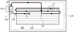
应予说明,在本实施方式中,如图4至图6所示,搬运车CV停在田地外。接着,在外周区域SA中,在搬运车CV的附近位置设定停车位置PP。如图5和图6所示,停车位置PP被设定在与脱离返回路径LW重叠的位置。It should be noted that, in this embodiment, as shown in FIGS. 4 to 6 , the transport vehicle CV is parked outside the field. Next, in the outer peripheral area SA, the parking position PP is set in the vicinity of the transport vehicle CV. As shown in FIGS. 5 and 6 , the parking position PP is set at a position overlapping with the escape return route LW.
搬运车CV能够收集并搬运联合收割机1从谷粒排出装置18排出的谷粒。在排出谷粒时,联合收割机1在停车位置PP停车,并且利用谷粒排出装置18将谷粒排出到搬运车CV。The conveyance vehicle CV can collect and convey the grain which the
联合收割机1持续进行割取行驶,如果谷粒箱14内的谷粒的量达到了规定量,则如图7所示,行驶控制部23控制联合收割机1的行驶以脱离割取行驶路径LI。另外,伴随着联合收割机1脱离割取行驶路径LI,割取离合器C15从接合状态切换到分离状态。The
应予说明,在本实施方式中,假设在图7所示的割取行驶路径LI上的位置P1,联合收割机1脱离割取行驶路径LI。In addition, in this embodiment, it is assumed that the
如图7所示,在联合收割机1脱离割取行驶路径LI之后,行驶控制部23控制联合收割机1以使其朝向脱离返回路径LW行驶。并且,如果联合收割机1到达了脱离返回路径LW附近,则行驶控制部23以通过沿着脱离返回路径LW的自动行驶进行非割取行驶的方式,对联合收割机1的行驶进行控制。As shown in FIG. 7, after the
在此,在联合收割机1脱离割取行进路径LI后,供给到脱粒装置13的割取谷秆的量减少。在本实施方式中,假设在联合收割机1脱离割取行驶路径LI之后,分选处理物量从等级5下降到等级1。并且,假设在分选处理物量为等级1的状态持续了第一期间的时刻,联合收割机1位于图7所示的位置P2。Here, after the
在该情况下,在联合收割机1到达位置P2的时刻,判定部25判定为脱粒装置13的脱粒效率降低。因此,在位置P2,脱粒装置停止部27将脱粒离合器C13从接合状态切换到切换状态。由此,停止脱粒装置13的驱动。In this case, the
如图7所示,联合收割机1在通过位置P2后,继续进行沿着脱离返回路径LW的自动行驶,并在停车位置PP停车。并且,利用谷粒排出装置18将谷粒排出到搬运车CV。As shown in FIG. 7 , the
在排出谷粒后,如图8所示,联合收割机1重新开始沿着脱离返回路径LW的自动行驶。并且,联合收割机1为了恢复到沿着割取行驶路径LI的自动行驶而在位置P3处转弯。该转弯是通过行驶控制部23的控制而自动进行的。After the grains are discharged, as shown in FIG. 8 , the
此时,脱粒装置开始部26将脱粒离合器C13从分离状态切换到接合状态。由此,在位置P3处重新开始脱粒装置13的驱动。另外,与此同时,割取离合器C15从分离状态切换到接合状态。接着,联合收割机1在割取行驶路径LI上的位置P4处,恢复到沿着割取行驶路径LI的自动行驶。At this time, the threshing
应予说明,本发明不限于此,也可以在联合收割机1接近了作业对象区域CA中的未割取部分的时刻,将脱粒离合器C13和割取离合器C15从分离状态切换到接合状态。例如,可以在联合收割机1的割取装置15和作业对象区域CA中的未割取部分之间的距离变为2米的时刻,脱粒离合器C13和割取离合器C15从分离状态切换到接合状态。In addition, this invention is not limited to this, You may switch the threshing clutch C13 and the reaping clutch C15 from disengaged state to engaged state when the
另外,关于联合收割机1恢复到沿着割取行驶路径LI的自动行驶的位置,其被确定为作业对象区域CA中的未割取部分中的距停车位置PP最近的位置。即,与联合收割机1脱离割取行驶路径LI的位置无关地,确定联合收割机1恢复到沿着割取行驶路径LI的自动行驶的位置。因此,上述位置P1和位置P4不同。Moreover, the position where the
并且,如果沿着作业对象区域CA中的所有的割取行驶路径LI的割取行驶都结束,则整个田地完成收获。And, when the harvesting travel along all the harvesting travel routes LI in the work target area CA is completed, the harvesting of the entire field is completed.
应予说明,如上说明,在本实施方式中,直到联合收割机1脱离割取行驶路径LI并开始沿着脱离返回路径LW行驶为止的期间,联合收割机1的行驶都在行驶控制部23的控制下通过自动行驶来进行。It should be noted that, as described above, in the present embodiment, the travel of the
另外,在本实施方式中,直到联合收割机1离开脱离返回路径LW并重新开始沿着割取行驶路径LI行驶为止的期间,联合收割机1的行驶都在行驶控制部23的控制下通过自动行驶来进行。In addition, in the present embodiment, until the
〔关于再计算返回路径〕[About recalculating the return path]
在联合收割机1恢复到沿着割取行驶路径LI的自动行驶时,脱离返回路径计算部22b能够计算出与脱离返回路径LW不同的再计算返回路径LR。再计算返回路径LR是用于供联合收割机1恢复到沿着割取行驶路径LI的自动行驶的行驶路径。以下,对再计算返回路径LR进行说明。When the
如上所述,控制部20具有行驶禁止区域存储部28。行驶禁止区域存储单元28存储着田地中的行驶禁止区域PA。如图2所示,脱离返回路径计算部22b从行驶禁止区域存储部28获取表示行驶禁止区域PA的数据。As described above, the
应予说明,行驶禁止区域PA是指田地中由于存在树木等原因而禁止联合收割机1行驶的区域。In addition, travel prohibition area|region PA is the area|region which prohibits the travel of the
另外,如图2所示,本车位置计算部21将联合收割机1的经时位置坐标向脱离返回路径计算部22b发送。Moreover, as shown in FIG. 2, the host vehicle
并且,脱离返回路径计算部22b基于从本车位置计算部21接收到的联合收割机1的经时位置坐标和从区域计算部24接收到的计算结果,计算出作业对象区域CA中的未割取区域CA1和已割取区域CA2。Then, the escape return
而且,脱离返回路径计算部22b基于从行驶禁止区域存储部28获取的表示行驶禁止区域PA的数据、联合收割机1的当前位置坐标、从区域计算部24接收到的计算结果以及如上所述地计算出的未割取区域CA1及已割取区域CA2,计算出再计算返回路径LR。Furthermore, the escape return
在此,按照以下三个条件来执行再计算返回路径LR的计算。即,再计算返回路径LR不能是通过行驶禁止区域PA的行驶路径。另外,再计算返回路径LR不能是通过田地外部的行驶路径。另外,再计算返回路径LR可以是通过已割取区域CA2的行驶路径。Here, calculation of the recalculation return route LR is performed according to the following three conditions. That is, the recalculated return route LR cannot be a travel route passing through the travel prohibition area PA. In addition, the recalculation return route LR cannot be a travel route passing outside the field. In addition, the recalculated return route LR may be a travel route passing through the already harvested area CA2.
以下,作为计算再计算返回路径LR的例子,对在图9所示的田地中计算再计算返回路径LR的情况下的流程进行说明。Hereinafter, as an example of calculating the recalculated return route LR, a flow in the case of calculating and recalculating the return route LR in the field shown in FIG. 9 will be described.
图9示出了联合收割机1从在停车位置PP停车的状态恢复到沿着割取行驶路径LI的自动行驶的情形。Fig. 9 shows a state in which the
在联合收割机1在停车位置PP停车期间,利用脱离返回路径计算部22b计算再计算返回路径LR。在该计算中,首先,在作业对象区域CA中的未收割区域CA1中,计算出距停车位置PP最近的位置。此时计算出的位置被确定为用于恢复到沿着割取行驶路径LI的自动行驶的位置。在图9所示的例子中,位置P5被确定为用于恢复到沿着割取行驶路径LI的自动行驶的位置。While the
接着,脱离返回路径计算部22b计算出作为再计算返回路径LR的候补的行驶路径。此时计算出的行驶路径是从停车位置PP到位置P5的行驶路径。Next, the departure and return
详细地说,脱离返回路径计算部22b首先计算出第一路线Rt1作为再计算返回路径LR的候补。第一路线Rt1是以使从停车位置PP到位置P5为止的行驶距离比较短的方式计算出的。Specifically, the departure and return
但是,第一路线Rt1横穿禁止行驶区域PA。即,第一路线Rt1是通过行驶禁止区域PA的行驶路径,所以从再计算返回路径LR的候补中排除。However, the first route Rt1 crosses the no-travel area PA. That is, the first route Rt1 is a travel route passing through the travel prohibition area PA, and therefore is excluded from the candidates for the recalculated return route LR.
接着,脱离返回路径计算部22b计算出第二路线Rt2和第三路线Rt3作为再计算返回路径LR的候选。第二路线Rt2和第三路线Rt3是以绕过行驶禁止区域PA的方式计算出的。第二路线Rt2和第三路线Rt3的长度彼此相同。Next, the departure return
在此,第二路线Rt2的一部分位于田地的外部。即,第二路线Rt2是通过田地外部的行驶路径,所以从再计算返回路径LR的候补中排除。Here, a part of the second route Rt2 is located outside the field. That is, the second route Rt2 is a travel route passing through the outside of the field, so it is excluded from the candidates for recalculating the return route LR.
另外,第三路线Rt3的一部分位于已割取区域CA2。即,第三路线Rt3是通过已割取区域CA2的行驶路径。另外,第三路径Rt3不是通过行驶禁止区域PA的行驶路径。另外,第三路线Rt3不是通过田地外部的行驶路径。因此,第三路线Rt3作为再计算返回路径LR的候选而被保留。In addition, a part of the third route Rt3 is located in the harvested area CA2. That is, the third route Rt3 is a traveling route passing through the harvested area CA2. In addition, the third route Rt3 is not a travel route passing through the travel prohibition area PA. In addition, the third route Rt3 is not a driving route passing outside the field. Therefore, the third route Rt3 is retained as a candidate for recalculating the return route LR.
即,在上述三个路线中,作为再计算返回路径LR的候补而保留下来的路线只有第三路线Rt3。因此,如图9所示,选择第三路线Rt3作为再计算返回路径LR。That is, among the above three routes, only the third route Rt3 remains as a candidate for recalculating the return route LR. Therefore, as shown in FIG. 9, the third route Rt3 is selected as the recalculation return route LR.
如以上说明,脱离返回路径计算部22b计算出再计算返回路径LR。接着,联合收割机1在行驶控制部23的控制下通过自动行驶沿着再计算返回路径LR行驶。由此,联合收割机1恢复到沿着割取行驶路径LI的自动行驶。As described above, the departure return
根据以上说明的结构,在联合收割机1脱离割取行驶路径LI后,在脱粒装置13的脱粒效率降低的情况下,利用脱粒装置停止部27停止脱粒装置13的驱动。因此,脱粒装置13的驱动很难产生浪费。由此,联合收割机1的油耗良好。According to the structure demonstrated above, when the threshing efficiency of the threshing
[第一实施方式的其他实施方式][Other embodiments of the first embodiment]
以下,对改变上述实施方式而得的其他实施方式进行说明。以下各实施方式中说明的事项以外的事项与上述实施方式中说明的事项相同。上述实施方式及以下各实施方式可以在不产生矛盾的范围内适当地组合。应予说明,本发明的范围并不限于上述实施方式及以下各其他实施方式。Hereinafter, other embodiments obtained by modifying the above-mentioned embodiments will be described. Matters other than those described in the following embodiments are the same as those described in the above-mentioned embodiments. The above-described embodiment and each of the following embodiments can be appropriately combined within a range that does not cause conflict. It should be noted that the scope of the present invention is not limited to the above-mentioned embodiment and the following other embodiments.
〔第一其他实施方式〕[First other embodiment]
在上述实施方式中,直到联合收割机1脱离割取行驶路径LI并开始沿着脱离返回路径LW行驶为止的期间,联合收割机1的行驶都在行驶控制部23的控制下通过自动行驶来进行。In the above-described embodiment, until the
另外,在上述实施方式中,直到联合收割机1离开脱离返回路径LW并重新开始沿着割取行驶路径LI行驶为止的期间,联合收割机1的行驶都在行驶控制部23的控制下通过自动行驶来进行。In addition, in the above-described embodiment, until the
但是,本发明不限于此。以下,以与上述实施方式的不同点为中心对第一实施方式的第一其他实施方式进行说明。以下说明的部分以外的结构与上述实施方式相同。另外,对于与上述实施方式相同的结构,标注了相同的附图标记。However, the present invention is not limited thereto. Hereinafter, a first other embodiment of the first embodiment will be described focusing on differences from the above-described embodiment. The configuration other than the parts described below is the same as that of the above-mentioned embodiment. In addition, the same code|symbol is attached|subjected to the same structure as the above-mentioned embodiment.
图10和图11是表示第一实施方式的第一其他实施方式中的联合收割机1的行驶的图。Fig. 10 and Fig. 11 are diagrams showing travel of the
在该第一其他实施方式中,通过由作业者手动操作联合收割机1,使联合收割机1脱离割取行驶路径LI。并且,在联合收割机1脱离割取行驶路径LI后,在行驶控制部23捕捉到脱离返回路径LW的情况下,开始在行驶控制部23的控制下自动行驶,联合收割机1进行沿着脱离返回路径LW的自动行驶。In this 1st other embodiment, the operator makes the
另外,在该第一其他实施方式中,通过由作业者手动操作联合收割机1,使联合收割机1离开脱离返回路径LW。并且,在联合收割机1离开脱离返回路径LW后,在行驶控制部23捕捉到割取行驶路径LI的情况下,开始在行驶控制部23的控制下自动行驶,联合收割机1进行沿着割取行驶路径LI的自动行驶。In addition, in this 1st other embodiment, the
即,在该第一其他实施方式中,在联合收割机1脱离割取行驶路径LI后,直到行驶控制部23捕捉到脱离返回路径LW为止的期间,都由作业者手动操作联合收割机1。同样地,在联合收割机1离开脱离返回路径LW后,直到行驶控制部23捕捉到割取行驶路径LI为止的期间,都由作业者手动操作联合收割机1。That is, in this 1st other embodiment, after the
以下,详细说明行驶控制部23捕捉脱离返回路径LW及割取行驶路径LI的情况。Hereinafter, the case where the
如图10所示,在联合收割机1脱离割取行驶路径LI后,行驶控制部23设定第一捕捉区域Ct1。第一捕捉区域Ct1是从联合收割机1的前端部的机体宽度方向中央位置向行进方向前侧扩展的扇形区域。另外,该扇形的半径和中心角是半径X和中心角w1。As shown in FIG. 10 , after the
在联合收割机1脱离割取行驶路径LI后,行驶控制部23监视第一捕捉区域Ct1是否与脱离返回路径LW重叠。另外,在联合收割机1脱离割取行驶路径LI后,行驶控制部23监视联合收割机1的前进方向相对于脱离返回路径LW的倾斜度即角度w2是否为规定角度WA以下。After the
并且,在第一捕捉区域Ct1与脱离返回路径LW重叠并且角度w2为规定角度WA以下时,行驶控制部23处于捕捉到脱离返回路径LW的状态。即,行驶控制部23捕捉到脱离返回路径LW与第一捕捉区域Ct1和脱离返回路径LW重叠且角度w2为规定角度WA以下是相同意思。Then, when the first capture region Ct1 overlaps the escape/return route LW and the angle w2 is equal to or less than the predetermined angle WA, the
如果行驶控制部23捕捉到脱离返回路径LW,则开始在行驶控制部23的控制下进行自动行驶,联合收割机1进行沿着脱离返回路径LW的自动行驶。When the running
另外,如图11所示,在联合收割机1离开脱离返回路径LW后,行驶控制部23设定第二捕捉区域Ct2。第二捕捉区域Ct2是从联合收割机1的前端部的机体宽度方向中央位置向前进方向前侧扩展的扇形区域。另外,该扇形的半径和中心角是半径Y和中心角r1。Moreover, as shown in FIG. 11, the traveling
在联合收割机1离开脱离返回路径LW后,行驶控制部23监视第二捕捉区域Ct2是否与割取行驶路径LI重叠。另外,在联合收割机1离开脱离返回路径LW后,行驶控制部23监视联合收割机1的前进方向相对于割取行驶路径LI的倾斜度即角度r2是否为规定角度RA以下。After the
并且,在第二捕捉区域Ct2与割取行驶路径LI重叠并且角度r2为规定角度RA以下时,行驶控制部23处于捕捉到割取行驶路径LI的状态。即,行驶控制部23捕捉到割取行驶路径LI与第二捕捉区域Ct2和割取行驶路径LI重叠且角度r2为规定角度RA以下是相同意思。Then, when the second capturing area Ct2 overlaps with the harvested traveling route LI and the angle r2 is equal to or smaller than the predetermined angle RA, the
如果行驶控制部23捕捉到割取行驶路径LI,则开始在行驶控制部23的控制下进行自动行驶,联合收割机1进行沿着割取行驶路径LI的自动行驶。When the
应予说明,如图10及图11所示,第二捕捉区域Ct2的半径Y小于第一捕捉区域Ct1的半径X。另外,第二捕捉区域Ct2的中心角r1小于第一捕捉区域Ct1的中心角w1。即,第二捕捉区域Ct2被设定为小于第一捕捉区域Ct1。It should be noted that, as shown in FIGS. 10 and 11 , the radius Y of the second capture region Ct2 is smaller than the radius X of the first capture region Ct1 . In addition, the central angle r1 of the second capture area Ct2 is smaller than the central angle w1 of the first capture area Ct1. That is, the second capture area Ct2 is set to be smaller than the first capture area Ct1.
另外,规定角度RA被设定为小于规定角度WA的角度。In addition, the predetermined angle RA is set to an angle smaller than the predetermined angle WA.
即,用于行驶控制部23捕捉到割取行驶路径LI的条件被设定为比用于行驶控制部23捕捉到脱离返回路径LW的条件更严格。由此,容易避免利用行驶控制部23捕捉到田地中的多条割取行驶路径LI中的、作业者意图之外的割取行驶路径LI的情况。另外,在作业者不希望沿着割取行驶路径LI行驶的情况下,容易避免利用行驶控制部23捕捉到割取行驶路径LI的情况。That is, the condition for the
另外,割取行驶路径LI及脱离返回路径LW是假想设定的行驶路径,并不是在实际的田地中作业者能够目视到的路径。因此,作业者在操作联合收割机1以使行驶控制部23捕捉脱离返回路径LW或割取行驶路径LI时,想定脱离返回路径LW或割取行驶路径LI的位置,操作联合收割机1以使其沿着该想定的脱离返回路径LW或割取行驶路径LI。In addition, the harvesting travel route LI and the escape return route LW are travel routes set virtually, and are not routes that can be seen by the operator in an actual field. Therefore, when the operator operates the
即,在作业者想定的脱离返回路径LW或割取行驶路径LI与实际的脱离返回路径LW或割取行驶路径LI偏移的情况下,行驶控制部23难以捕捉到脱离返回路径LW或割取行驶路径LI。That is, when the departure return route LW or harvesting travel route LI assumed by the operator deviates from the actual departure return route LW or harvesting travel route LI, it is difficult for the
在此,在开始沿着割取行驶路径LI行驶的情况下,该割取行驶路径LI大多位于田地的作业对象区域CA中的未割取部分的端部,并且沿着未割取部分和已割取部分之间的边界线延伸。因此,作业者想定的割取行驶路径LI与实际的割取行驶路径LI的偏移容易比较小。Here, when starting to travel along the harvested travel route LI, the harvested travel route LI is often located at the end of the uncut part of the work target area CA of the field, and along the uncut part and the Boundary lines between cut sections are extended. Therefore, the deviation between the harvesting travel route LI assumed by the operator and the actual harvesting travel route LI tends to be relatively small.
相对于此,在脱离返回路径LW的附近,大多不存在用于帮助作业者高精度地想定脱离返回路径LW的位置的记号。因此,作业者想定的脱离返回路径LW与实际的脱离返回路径LW的偏移容易比较大。由此,行驶控制部23难以捕捉到脱离返回路径LW。On the other hand, in the vicinity of the departure return route LW, there are often no marks for helping the operator to accurately imagine the position of the departure return route LW. Therefore, the deviation between the escape and return route LW assumed by the operator and the actual escape and return route LW tends to be relatively large. This makes it difficult for the
因此,如上所述,用于行驶控制部23捕捉到脱离返回路径LW的条件被设定得比用于行驶控制部23捕捉到割取行驶路径LI的条件缓和。由此,容易避免行驶控制部23无法捕捉到脱离返回路径LW的情况。Therefore, as described above, the condition for the
应予说明,可以同时设定第一捕捉区域Ct1和第二捕捉区域Ct2。即,在联合收割机1在不是脱离返回路径LW也不是割取行驶路径LI的位置行驶时,行驶控制部23能够将脱离返回路径LW和割取行驶路径LI都捕捉到。在该情况下,也可以沿着脱离返回路径LW及割取行驶路径LI中的行驶控制部23先捕捉到的一方的行驶路径进行自动行驶。It should be noted that the first capture region Ct1 and the second capture region Ct2 may be set simultaneously. That is, when the
〔其他实施方式〕[Other Embodiments]
(1)行驶装置11还可以是轮式,也可以是半履带式。(1) The traveling
(2)在上述实施方式中,由割取行驶路径计算部22a计算出的割取行驶路径LI是相互平行的多条平行线,但本发明不限于此,由割取行驶路径计算部22a计算出的割取行驶路径LI也可以不是相互平行的多条平行线。例如,由割取行驶路径计算部22a计算出的割取行驶路径LI也可以是旋涡状的行驶路径。(2) In the above-mentioned embodiment, the cutting running route LI calculated by the cutting running
(3)在上述实施方式中,作业者手动操作联合收割机1,如图4所示,在田地内的外周部分,以沿田地的边界线环绕的方式进行割取行驶。但是,本发明不限于此,也可以构成为联合收割机1自动行驶,在田地内的外周部分,以沿田地的边界线环绕的方式进行割取行驶。(3) In the above-described embodiment, the operator manually operates the
(4)在上述实施方式中,在分选处理物量为等级1的状态持续了规定的第一期间以上的情况下,判定部25判定为脱粒装置13的脱粒效率降低。但是,本发明不限于此。例如,判定部25可以构成为,在分选处理物量的等级降低的情况下,判定为脱粒装置13的脱粒效率降低。即,分选处理物量的等级降低相当于由筛传感器S1检测到的分选处理物量减少。(4) In the said embodiment, the
(5)本车位置计算部21、路径计算部22、行驶控制部23、区域计算部24、判定部25、脱粒装置开始部26、脱粒装置停止部27、行驶禁止区域存储部28中的一部分或全部可以设置在联合收割机1的外部,例如,也可以设置在设置于联合收割机1的外部的管理服务器。(5) A part of the host vehicle
(6)也可以不设置脱离返回路径计算部22b。(6) The escape return
(7)也可以不设置行驶禁止区域存储部28。(7) The travel prohibition
(8)也可以不设置脱粒装置开始部26。(8) The threshing
(9)也可以不设置筛传感器S1。(9) The sieve sensor S1 may not be provided.
(10)也可以不设置割取离合器传感器S2。(10) The reaping clutch sensor S2 may not be provided.
(11)也可以不设置通信终端4。(11) The communication terminal 4 may not be provided.
(12)由割取行驶路径计算部22a计算出的割取行驶路径LI可以是直线状的路径,也可以是弯曲的路径。另外,由脱离返回路径计算部22b计算出的脱离返回路径LW可以是直线状的路径,也可以是弯曲的路径。(12) The harvesting traveling route LI calculated by the harvesting traveling
(13)也可以构成为使计算机实现上述实施方式中的各部件的功能的联合收割机控制程序。另外,也可以构成为存储有使计算机实现上述实施方式中的各部件的功能的联合收割机控制程序的存储介质。另外,在上述实施方式中,也可以构成为通过多个步骤进行由各部件进行的作业的联合收割机控制方法。(13) It may be comprised as the combine control program which makes a computer realize the function of each component in said embodiment. Moreover, you may comprise as the storage medium which memorize|stored the combine control program which makes a computer realize the function of each component in said embodiment. In addition, in the said embodiment, you may comprise as a combine control method which performs the work by each member in a plurality of steps.
[第二实施方式][Second Embodiment]
以下,参照图12~图19,对本发明的第二实施方式进行说明。另外,对于方向的记载,只要没有特别的说明,就将图12所示的箭头F的方向设为“前”,将箭头B的方向设为“后”。另外,将图12所示的箭头U的方向设为“上”,将箭头D的方向设为“下”。Hereinafter, a second embodiment of the present invention will be described with reference to FIGS. 12 to 19 . In the description of directions, unless otherwise specified, the direction of the arrow F shown in FIG. 12 is referred to as "front", and the direction of the arrow B is referred to as "rear". In addition, let the direction of the arrow U shown in FIG. 12 be "up", and let the direction of the arrow D be "down".
〔联合收割机的整体结构〕〔The overall structure of the combine harvester〕
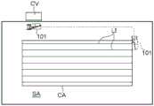
如图12所示,全喂入式的联合收割机101(相当于本发明的“收获机”)具备履带式的行驶装置111、驾驶部112、脱粒装置113、谷粒箱114(相当于本发明的“收获物箱”)、收获装置H、输送装置116、谷粒排出装置118(相当于本发明的“排出装置”)、卫星定位模块180。As shown in Figure 12, the combine harvester 101 (equivalent to the "harvester" of the present invention) of the full-feeding type is equipped with a crawler-
行驶装置111在联合收割机101中设置于下部。联合收割机101可以利用行驶装置111而自走行驶。The traveling
另外,驾驶部112、脱粒装置113、谷粒箱114设置在行驶装置111的上侧。监视联合收割机101的作业的作业者能够搭乘于驾驶部112。应予说明,作业者也可以从联合收割机101的机外监视联合收割机101的作业。Moreover, the driving
谷粒排出装置118设置在谷粒箱114的上侧。另外,卫星定位模块180安装于驾驶部112的上表面。The
收获装置H在联合收割机101中设置于前部。并且,输送装置116设置在收获装置H的后侧。另外,收获装置H具有割取装置115和滚筒117。The harvesting apparatus H is installed in the front part in the
割取装置115割取田地的植立谷秆。另外,滚筒117在旋转驱动的同时拨入收获对象的植立谷秆。通过该结构,收获装置H收获田地的谷物(相当于本发明的“农作物”)。并且,联合收割机101可以进行在利用割取装置115割取田地的植立谷秆的同时利用行驶装置111进行行驶的割取行驶。The
由割取装置115割取的割取谷秆利用输送装置116输送到脱粒装置113。在脱粒装置113中,对割取谷秆进行脱粒处理。通过脱粒处理获得的谷粒(相当于本发明的“收获物”)存储于谷粒箱114。存储于谷粒箱114的谷粒根据需要通过谷粒排出装置118排出到机外。The harvested grain stalks harvested by the
由此,联合收割机101具有收获田地的谷物的收获装置H、存储由收获装置H收获的谷粒的谷粒箱114以及排出存储于谷粒箱114的谷粒的谷粒排出装置118。Thereby, the
另外,如图12所示,在驾驶部112配置有通信终端104。通信终端104被构成为能够显示各种信息。在本实施方式中,通信终端104固定于驾驶部112。但是,本发明不限于此,通信终端104可以构成为能够相对于驾驶部112装卸,通信终端104也可以位于联合收割机101的机外。In addition, as shown in FIG. 12 , a
另外,如图13所示,联合收割机101包括发动机51以及排出离合器C18。Moreover, as shown in FIG. 13, the
从发动机151输出的动力被分配到排出离合器C18和行驶装置111。行驶装置111由来自发动机151的动力驱动。The motive power output from the
另外,排出离合器C18构成为能够在传递动力的接合状态和不传递动力的分离状态之间改变状态。In addition, the discharge clutch C18 is configured to be capable of changing a state between an engaged state in which power is transmitted and a disengaged state in which power is not transmitted.
在排出离合器C18处于分离状态时,从发动机151输出的动力不被传递到谷粒排出装置118。此时,谷粒排出装置118处于非驱动状态。When the discharge clutch C18 is in the disengaged state, the power output from the
在排出离合器C18处于接合状态时,从发动机151输出的动力被传递到谷粒排出装置118。此时,谷粒排出装置118由来自发动机151的动力驱动。即,此时,谷粒排出装置118处于驱动状态。When the discharge clutch C18 is in the engaged state, the motive power output from the
在此,联合收割机101构成为,在如图14所示地在田地的外周侧的区域一边收获谷物一边进行环绕行驶之后,如图16所示地在田地的内侧的区域进行割取行驶,从而收获田地的谷物。Here, the
并且,在收获作业中,联合收割机101由收割机控制系统A1控制。以下,对收获机控制系统A1的结构进行说明。Moreover, in harvesting work, the
〔收获机控制系统的结构〕[Structure of Harvester Control System]
如图13所示,收获机控制系统A1具备卫星定位模块180、本车方位检测装置181、控制部120、通信终端104。应予说明,本车方位检测装置181和控制部120设置在联合收割机101中。另外,如上所述,卫星定位模块180和通信终端104也设置在联合收割机101中。As shown in FIG. 13 , the harvester control system A1 includes a
控制部120具有本车位置计算部121、路径计算部122、行驶控制部123、区域计算部124、手动操作信号发送部125、位置存储部126、位置设定部127、方向存储部128、方向设定部129、排出离合器传感器S11。The
如图12所示,卫星定位模块180接收来自GPS(全球卫星定位系统)所使用的人造卫星GS的GPS信号。并且,如图13所示,卫星定位模块180基于接收到的GPS信号,将表示联合收割机101的本车位置的定位数据发送到本车位置计算部121。As shown in FIG. 12, the
本车位置计算部121基于由卫星定位模块180输出的定位数据,按照时间顺序计算出联合收割机101的位置坐标。计算出的联合收割机101的经时位置坐标被发送到行驶控制部123和区域计算部124。The own vehicle
区域计算部124基于从本车位置计算部121接收到的联合收割机101的经时位置坐标,如图15所示,计算出外周区域SA和作业对象区域CA。The
更具体地说,区域计算部124基于从本车位置计算部121接收到的联合收割机101的经时位置坐标,计算出田地的外周侧的环绕行驶中的联合收割机101的行驶轨迹。并且,区域计算部124基于计算出的联合收割机101的行驶轨迹,计算出联合收割机101在收获谷物的同时进行环绕行驶的田地的外周侧的区域,将其作为外周区域SA。另外,区域计算部124将计算出的外周区域SA的内部作为作业对象区域CA计算出来。More specifically, the
例如,在图14中,用箭头表示了用于在田地的外周侧进行环绕行驶的联合收割机101的行驶路径。在图14所示的例子中,联合收割机101进行3周的环绕行驶。并且,如果完成了沿着该行驶路径的割取行驶,则田地变为图15所示的状态。For example, in FIG. 14, the traveling route of the
如图15所示,区域计算部124计算出联合收割机1在收获谷物的同时进行环绕行驶的田地的外周侧的区域,将其为外周区域SA。另外,区域计算部124将计算出的外周区域SA的内侧作为作业对象区域CA计算出来。As shown in FIG. 15, the
并且,如图13所示,区域计算部124的计算结果被发送到路径计算部122。Then, as shown in FIG. 13 , the calculation result of the
路径计算部122基于从区域计算部124接收到的计算结果,如图15所示,计算出用于在作业对象区域CA中进行割取行驶的行驶路径即割取行驶路径LI。应予说明,如图15所示,在本实施方式中,割取行驶路径LI是相互平行的多条平行线。Based on the calculation results received from the
如图13所示,由路径计算部122计算出的割取行驶路径LI被发送到行驶控制部123。As shown in FIG. 13 , the cut travel route LI calculated by the
行驶控制部123构成为能够控制行驶装置111。并且,行驶控制部123基于从本车位置计算部121接收到的联合收割机101的位置坐标和从路径计算部122接收到的割取行驶路径LI,控制联合收割机101的自动行驶。更具体地,如图16所示,行驶控制部123以通过沿着割取行驶路径LI的自动行驶进行割取行驶的方式,对联合收割机101的行驶进行控制。Travel control unit 123 is configured to be able to control
在通过手动操作来移动了联合收割机101的情况下,手动操作信号发送部125将规定的信号发送到位置存储部126和方向存储部128。该信号是表示联合收割机101通过手动操作而移动的信号。When the
另外,本车位置计算部121将联合收割机101的位置坐标发送到位置存储部126。Moreover, the vehicle
另外,排出离合器传感器S11检测排出离合器C18的接合/分离状态。排出离合器传感器S11的检测结果被发送到位置存储部126和方向存储部128。In addition, the discharge clutch sensor S11 detects the engagement/disengagement state of the discharge clutch C18. The detection result of the discharge clutch sensor S11 is sent to the
在联合收割机101在通过手动操作而移动到的目的地位置利用谷粒排出装置118进行了排出作业的情况下,位置存储部126存储通过谷粒排出装置118进行排出作业的时刻的联合收割机101的停车位置。When the
更具体地,位置存储部126基于来自手动操作信号发送部125的信号和排出离合器传感器S11的检测结果,监视联合收割机101是否在通过手动操作而移动到的目的地位置利用谷粒排出装置118进行了排出作业。More specifically, the
应予说明,在从排出离合器传感器S11向位置存储部126发送了表示排出离合器C18从分离状态切换到了接合状态的检测结果的情况下,位置存储部126判定为通过谷粒排出装置118进行了排出作业。It should be noted that when the detection result indicating that the discharge clutch C18 has been switched from the disengaged state to the engaged state is transmitted from the discharge clutch sensor S11 to the
并且,在联合收割机101在通过手动操作而移动到的目的地位置利用谷粒排出装置118进行了排出作业的情况下,位置存储部126存储该时刻的联合收割机101的停车位置。And the
由此,收获机控制系统A1具备位置存储部126,在联合收割机101在通过手动操作而移动到的目的地位置利用谷粒排出装置118进行了排出作业的情况下,该位置存储部126存储利用谷粒排出装置118进行排出作业的时刻的联合收割机101的停车位置。Thus, the harvester control system A1 is equipped with the
存储于位置存储部126的停车位置被发送到位置设定部127。并且,位置设定部127基于存储于位置存储部126的联合收割机101的停车位置来设定目标停车位置TP。由位置设定部127设定的目标停车位置TP被发送到行驶控制部123。The parking position stored in the
由此,收获机控制系统A1具备位置设定部127,该位置设定部127基于存储于位置存储部126的联合收割机101的停车位置来设定目标停车位置TP。Thereby, harvester control system A1 is equipped with the
本车方位检测装置181检测联合收割机101的机体的方向。并且,如图13所示,本车方位检测装置181的检测结果被发送到方向存储部128。The vehicle
在联合收割机101在通过手动操作而移动到的目的地位置利用谷粒排出装置118进行了排出作业的情况下,方向存储部128存储利用谷粒排出装置118进行排出作业的时刻的联合收割机101的机体的方向。When the
更具体地说,方向存储部128基于来自手动操作信号发送部125的信号和排出离合器传感器S11的检测结果,监视联合收割机101是否在通过手动操作而移动到的目的地位置利用谷粒排出装置118进行了排出作业。More specifically, the
应予说明,在从排出离合器传感器S11向方向存储部128发送了表示排出离合器C18从分离状态切换到了接合状态的检测结果的情况下,方向存储部128判定为通过谷粒排出装置118进行了排出作业。It should be noted that when the detection result indicating that the discharge clutch C18 has been switched from the disengaged state to the engaged state is sent from the discharge clutch sensor S11 to the
并且,在联合收割机101在通过手动操作而移动到的目的地位置利用谷粒排出装置118进行了排出作业的情况下,方向存储部128存储该时刻的联合收割机101的机体的方向And when the
由此,收获机控制系统A1具备方向存储部128,在联合收割机101在通过手动操作而移动到的目的地位置利用谷粒排出装置118进行了排出作业的情况下,该方向存储部128存储利用谷粒排出装置118进行排出作业的时刻的联合收割机101的机体的方向Thus, the harvester control system A1 is provided with the
存储于方向存储部128的机体的方向被发送到方向设定部129。并且,方向设定部129基于存储于方向存储部128的联合收割机101的机体的方向来设定目标停车方向TD。由方向设定部129设定的目标停车方向TD被发送到行驶控制部123。The direction of the body stored in the
由此,收获机控制系统A1具备方向设定部129,该方向设定部129基于存储于方向存储部128的联合收割机101的机体的方向来设定目标停车方向TD。Thereby, harvester control system A1 is equipped with the
并且,在利用谷粒排出装置118进行排出作业的情况下,行驶控制部123以使联合收割机101在朝向目标停车方向TD的状态下自动地在目标停车位置TP停车的方式控制联合收割机101的行驶。And when performing discharge work by the
由此,收获机控制系统A1具有行驶控制部123,在利用谷粒排出装置118进行排出作业的情况下,该行驶控制部123以使联合收割机101自动地在目标停车位置TP停车的方式控制联合收割机101的行驶。Thus, the harvester control system A1 has the running control unit 123 that controls the
〔利用了联合收割机控制系统的收获作业的流程〕〔Flow of harvesting operation using combine harvester control system〕
以下,作为利用了收获机控制系统A1的收获作业的例子,对联合收割机101在图14所示的田地进行收获作业的情况下的流程进行说明。Hereinafter, as an example of the harvesting work using the harvester control system A1, the flow in the case where the
最初,作业者手动操作联合收割机101,如图14所示,在田地内的外周部分,以沿田地的边界线环绕的方式进行割取行驶。在图14所示的例子中,联合收割机101进行3周的环绕行驶。如果完成了该环绕行驶,则田地变为图15所示的状态。First, an operator manually operates the
区域计算部124基于从本车位置计算部121接收到的联合收割机101的经时位置坐标,计算出图14所示的环绕行驶中的联合收割机101的行驶轨迹。并且,如图15所示,区域计算部124基于计算出的联合收割机101的行驶轨迹,计算出联合收割机101在割取植立谷秆的同时进行环绕行驶的田地的外周侧的区域,将其为外周区域SA。另外,区域计算部124将计算出的外周区域SA的内侧作为作业对象区域CA计算出来。The
接着,路径计算部122基于从区域计算部124接收到的计算结果,如图15所示,设定作业对象区域CA中的割取行驶路径LI。Next, the
在图15所示的例子中,在开始作业对象区域CA中的收获作业前,联合收割机101通过手动操作向搬运车CV的附近移动。应予说明,在本实施方式中,搬运车CV在田地外停车。In the example shown in FIG. 15, the
并且,在联合收割机101在车辆CV的附近停车后,驱动谷粒排出装置118,排出谷粒。搬运车CV能够收集并搬运联合收割机101从谷粒排出装置118排出的谷粒。And after the
此时,位置存储部126存储利用谷粒排出装置118进行排出作业的时刻的联合收割机101的停车位置。另外,方向存储部128存储利用谷粒排出装置118进行排出作业的时刻的联合收割机101的机体的方向。At this time, the position memory|
并且,如图16所示,基于由位置存储部126存储的停车位置,利用位置设定部127设定目标停车位置TP。另外,基于由方向存储部128存储的机体的方向,利用方向设定部129设定目标停车方向TD。Then, as shown in FIG. 16 , based on the parking position stored in the
并且,通过由作业者按下自动行驶开始按钮(未图示),如图16所示,开始沿着割取行驶路径LI的自动行驶。此时,行驶控制部123以通过沿着割取行驶路径LI的自动行驶进行割取行驶的方式,对联合收割机101的行驶进行控制。Then, when an operator presses an automatic travel start button (not shown), as shown in FIG. 16 , automatic travel along the harvesting travel route LI is started. At this time, the traveling control part 123 controls the traveling of the
联合收割机101持续进行割取行驶,如果谷粒箱114内的谷粒的量达到了规定量,则如图17所示,行驶控制部123以使联合收割机101脱离割取行驶路径LI而向目标停车位置TP移动的方式控制联合收割机101的行驶。
接着,通过行驶控制部123的控制,联合收割机101在朝向目标停车方向TD的状态下自动地在目标停车位置TP停车。而且,驱动谷粒排出装置118,将谷粒排出到搬运车CV。如果谷粒排出装置118完成了排出作业,则联合收割机101恢复到沿着割取行驶路径LI的割取行驶。Next, the
并且,如果沿着作业对象区域CA中的所有的割取行驶路径LI的割取行驶都结束,则整个田地完成收获。And, when the harvesting travel along all the harvesting travel routes LI in the work target area CA is completed, the harvesting of the entire field is completed.
根据以上说明的结构,如果在田地的收获作业中进行了最初的排出作业,则利用位置存储部126存储该时刻的联合收割机101的停车位置。并且,在第二次以后的排出作业中,通过行驶控制部123的控制,使联合收割机101自动地在存储的停车位置停车。According to the structure demonstrated above, the parking position of the
即,根据以上说明的结构,仅最初的排出作业需要通过手动操作使联合收割机101在用于排出的位置停车。由此,能够减轻作业者的操作负担。That is, according to the structure demonstrated above, only the first discharge operation needs to park the
〔关于经由通信终端的目标停车位置的设定〕[About the setting of the target parking position via the communication terminal]
另外,收获机控制系统A1构成为,在田地的收获作业中,在通过谷粒排出装置118进行最初的排出作业之前,作业者能够经由通信终端104设定目标停车位置TP。Moreover, the harvester control system A1 is comprised so that an operator can set the target parking position TP via the
以下,对经由通信终端104的目标停车位置TP的设定进行说明。Hereinafter, setting of the target parking position TP via the
如图13所示,通信终端104具有操作部104a以及信号输出部104b。如图18所示,操作部104a由触摸面板构成。并且,作业者在田地的收获作业中,在进行谷粒排出装置118的最初的排出作业之前,能够通过操作操作部104a来设定目标停车位置TP。As shown in FIG. 13, the
详细地说,如图18所示,在操作部104a显示田地的整体图。并且,通过由作业者触摸操作部104a的任意部位,在被触摸的部位显示表示目标停车位置TP的标记。Specifically, as shown in FIG. 18 , an overall view of the field is displayed on the
并且,如图13所示,表示由作业者触摸的部位的信号被从操作部104a发送到信号输出部104b。信号输出部104b基于从操作部104a接收到的信号,输出指示信号。Then, as shown in FIG. 13 , a signal indicating a site touched by the operator is sent from the
该指示信号是对联合收割机101为了利用谷粒排出装置118进行排出作业的停车位置进行指示的信号。并且,该指示信号被发送到位置设定部127。This instruction signal is a signal which instructs the parking position for the
由此,收获机控制系统A1具备信号输出部104b,所述信号输出部104b输出对联合收割机101为了利用谷粒排出装置118进行排出作业的停车位置进行指示的指示信号。Thereby, the harvester control system A1 is equipped with the signal output part 104b which outputs the instruction|command signal which instructs the parking position of the
并且,此时,位置设定部127基于从信号输出部104b接收到的指示信号,设定目标停车位置TP。In addition, at this time, the
由此,位置设定部127构成为,在田地的收获作业中,在利用谷粒排出装置118进行最初的排出作业之前利用信号输出部104b输出了指示信号的情况下,基于指示信号来设定目标停车位置TP。Thus, the
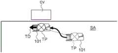
根据以上结构,作业者在田地的收获作业中,在利用谷粒排出装置118进行最初的排出作业前,能够通过操作操作部104a来设定目标停车位置TP。并且,在进行排出作业的情况下,联合收割机101自动地在基于来自信号输出部104b的指示信号而设定的目标停车位置TP停车。According to the said structure, an operator can set the target parking position TP by operating the
在此,基于来自信号输出部104b的指示信号而设定的目标停车位置TP是基于作业者的触摸操作而设定的。因此,目标停车位置TP有时是距搬运车CV较远的位置。Here, the target parking position TP set based on the instruction signal from the signal output unit 104b is set based on the operator's touch operation. Therefore, the target parking position TP may be a position far from the transport vehicle CV.
在该情况下,如图19所示,在联合收割机101自动在基于来自信号输出部104b的指示信号而设定的目标停车位置TP停车后,作业者能够通过手动操作使移动联合收割机101从该位置移动。In this case, as shown in FIG. 19 , after the
并且,在联合收割机101通过手动操作移动后利用谷粒排出装置118进行了排出作业的情况下,位置存储部126存储利用谷粒排出装置118进行排出作业的时刻的联合收割机101的停车位置。另外,方向存储部128存储利用谷粒排出装置118进行排出作业的时刻的联合收割机101的机体的方向。Moreover, when the
位置设定部127基于此时存储于位置存储部126的停车位置,如图19所示,重新设定目标停车位置TP。另外,方向设定部129基于此时存储于方向存储部128的机体的方向,如图19所示,设定目标停车方向TD。Based on the parking position stored in the
由此,在联合收割机101通过手动操作而从基于指示信号设定的目标停车位置TP移动后,利用谷粒排出装置118进行了排出作业的情况下,位置设定部127基于存储于位置存储部126的联合收割机101的停车位置而重新设定目标停车位置TP。Thus, when the
[第二实施方式的其他实施方式][Other embodiments of the second embodiment]
以下,对改变上述实施方式而得的其他实施方式进行说明。以下各实施方式中说明的事项以外的事项与上述实施方式中说明的事项相同。上述实施方式及以下各实施方式可以在不产生矛盾的范围内适当地组合。应予说明,本发明的范围并不限于上述实施方式及以下各其他实施方式。Hereinafter, other embodiments obtained by modifying the above-mentioned embodiments will be described. Matters other than those described in the following embodiments are the same as those described in the above-mentioned embodiments. The above-described embodiment and each of the following embodiments can be appropriately combined within a range that does not cause conflict. It should be noted that the scope of the present invention is not limited to the above-mentioned embodiment and the following other embodiments.
(1)行驶装置111还可以是轮式,也可以是半履带式。(1) The traveling
(2)在上述实施方式中,由路径计算部122计算出的割取行驶路径LI是相互平行的多条平行线,但本发明不限于此,由路径计算部122计算出的割取行驶路径LI也可以不是相互平行的多条平行线。例如,由路径计算部122计算出的割取行驶路径LI也可以是旋涡状的行驶路径。(2) In the above-mentioned embodiment, the cutting travel route LI calculated by the
(3)在上述实施方式中,作业者手动操作联合收割机101,如图14所示,在田地内的外周部分,以沿田地的边界线环绕的方式进行割取行驶。但是,本发明不限于此,也可以构成为联合收割机101自动行驶,在田地内的外周部分以沿田地的边界线环绕的方式进行割取行驶。(3) In the said embodiment, a worker manually operates the
(4)沿着割取行驶路径LI的割取行驶也可以由作业者通过手动操作联合收割机101来进行。(4) The harvesting traveling along the harvesting traveling route LI may be performed by an operator manually operating the
(5)本车位置计算部121、路径计算部122、行驶控制部123、区域计算部124、手动操作信号发送部125、位置存储部126、位置设定部127、方向存储部128、方向设定部129中的一部分或全部也可以设置在联合收割机101的外部,例如,也可以设置在设置于联合收割机101的外部的管理服务器。(5) The vehicle
(6)也可以不设置方向存储部128。(6) The
(7)也可以不设置方向设定部129。(7) The
(8)也可以不设置信号输出部104b。(8) The signal output unit 104b may not be provided.
(9)可以不设置通信终端104。(9) The
(10)由路径计算部122计算出的割取行驶路径LI可以是直线状的路径,也可以是弯曲的路径。(10) The cutting travel route LI calculated by the
(11)也可以构成为使计算机实现上述实施方式中的各部件的功能的收获机控制程序。另外,也可以构成为存储有使计算机实现上述实施方式中的各部件的功能的收获机控制程序的存储介质。另外,在上述实施方式中,也可以构成为通过多个步骤进行由各部件进行的作业的收获机控制方法。(11) It may be configured as a harvester control program that causes a computer to realize the functions of the respective components in the above-described embodiments. Moreover, you may comprise as a storage medium which stored the harvester control program which makes a computer realize the function of each component in the said embodiment. In addition, in the said embodiment, you may comprise as a harvester control method which performs the operation|work by each member in a plurality of steps.
工业实用性Industrial Applicability
本发明不仅可以用于全喂入型的联合收割机,也可以用于半喂入型的联合收割机。The present invention can be used not only for full-feeding combine harvesters, but also for half-feeding combine harvesters.
另外,本发明不仅可以用于全喂入型的联合收割机,也可以用于半喂入型的联合收割机。另外,也能够用于玉米收获机、马铃薯收获机、胡萝卜收获机、甘蔗收获机等各种收获机。In addition, the present invention can be used not only for a full-feed type combine but also for a half-feed type combine. Moreover, it can also be used for various harvesters, such as a corn harvester, a potato harvester, a carrot harvester, and a sugarcane harvester.
附图标记说明Explanation of reference signs
<第一实施方式><First Embodiment>
1联合收割机1 combine harvester
13脱粒装置13Threshing device
13b摆动分选部13b swing sorting department
15割取装置15 harvesting device
20控制部20 control department
22路径计算部22 Path Computation Department
22a割取行驶路径计算部22a harvesting travel route calculation unit
23行驶控制部(自动割取行驶控制部)23 Driving control unit (automatic harvesting driving control unit)
25判定部25 Judgment Department
26脱粒装置开始部26 The beginning of the threshing unit
27脱粒装置停止部27 Thresher stop part
A联合收割机控制系统A combine harvester control system
LI割取行驶路径LI cuts the driving path
S1筛传感器S1 sieve sensor
<第二实施方式><Second Embodiment>
101联合收割机(收获机)101 combine harvester (harvester)
104b信号输出部104b signal output unit
114谷粒箱(收获物箱)114 grain box (harvest box)
118谷粒排出装置(排出装置)118 grain discharge device (discharge device)
123行驶控制部123 Driving Control Department
126位置存储部126 position storage unit
127位置设定部127 Position Setting Department
128方向存储部128 direction storage department
129方向设定部129 Direction Setting Department
A1 收获机控制系统A1 harvester control system
H 收获装置H Harvesting device
TD 目标停车方向TD target parking direction
TP 目标停车位置TP target parking position
Claims (6)
Applications Claiming Priority (5)
| Application Number | Priority Date | Filing Date | Title |
|---|---|---|---|
| JP2017242049AJP6843037B2 (en) | 2017-12-18 | 2017-12-18 | Combine control system |
| JP2017-242049 | 2017-12-18 | ||
| JP2017245308AJP7142433B2 (en) | 2017-12-21 | 2017-12-21 | harvester control system |
| JP2017-245308 | 2017-12-21 | ||
| PCT/JP2018/045590WO2019124174A1 (en) | 2017-12-18 | 2018-12-12 | Combine control system, combine control program, recording medium with combine control program recorded therein, combine control method, harvester control system, harvester control program, recording medium with harvester control program recorded therein, and harvester control method |
Publications (2)
| Publication Number | Publication Date |
|---|---|
| CN111386033A CN111386033A (en) | 2020-07-07 |
| CN111386033Btrue CN111386033B (en) | 2023-05-23 |
Family
ID=66994215
Family Applications (1)
| Application Number | Title | Priority Date | Filing Date |
|---|---|---|---|
| CN201880074147.1AActiveCN111386033B (en) | 2017-12-18 | 2018-12-12 | Combine harvester control system and its program, method and storage medium |
Country Status (3)
| Country | Link |
|---|---|
| KR (1) | KR102788976B1 (en) |
| CN (1) | CN111386033B (en) |
| WO (1) | WO2019124174A1 (en) |
Families Citing this family (57)
| Publication number | Priority date | Publication date | Assignee | Title |
|---|---|---|---|---|
| US11589509B2 (en) | 2018-10-26 | 2023-02-28 | Deere & Company | Predictive machine characteristic map generation and control system |
| US11672203B2 (en) | 2018-10-26 | 2023-06-13 | Deere & Company | Predictive map generation and control |
| US12069978B2 (en) | 2018-10-26 | 2024-08-27 | Deere & Company | Predictive environmental characteristic map generation and control system |
| US11957072B2 (en) | 2020-02-06 | 2024-04-16 | Deere & Company | Pre-emergence weed detection and mitigation system |
| US11641800B2 (en) | 2020-02-06 | 2023-05-09 | Deere & Company | Agricultural harvesting machine with pre-emergence weed detection and mitigation system |
| US11653588B2 (en) | 2018-10-26 | 2023-05-23 | Deere & Company | Yield map generation and control system |
| US11079725B2 (en) | 2019-04-10 | 2021-08-03 | Deere & Company | Machine control using real-time model |
| US11467605B2 (en) | 2019-04-10 | 2022-10-11 | Deere & Company | Zonal machine control |
| US11778945B2 (en) | 2019-04-10 | 2023-10-10 | Deere & Company | Machine control using real-time model |
| US12225846B2 (en) | 2020-02-06 | 2025-02-18 | Deere & Company | Machine control using a predictive map |
| US12035648B2 (en) | 2020-02-06 | 2024-07-16 | Deere & Company | Predictive weed map generation and control system |
| US12329148B2 (en) | 2020-02-06 | 2025-06-17 | Deere & Company | Predictive weed map and material application machine control |
| US11477940B2 (en) | 2020-03-26 | 2022-10-25 | Deere & Company | Mobile work machine control based on zone parameter modification |
| JP7515362B2 (en)* | 2020-10-02 | 2024-07-12 | 株式会社クボタ | combine |
| JP7542388B2 (en)* | 2020-10-02 | 2024-08-30 | 株式会社クボタ | Agricultural machinery |
| JP7645625B2 (en)* | 2020-10-02 | 2025-03-14 | 株式会社クボタ | Agricultural machinery |
| US11592822B2 (en) | 2020-10-09 | 2023-02-28 | Deere & Company | Machine control using a predictive map |
| US11635765B2 (en) | 2020-10-09 | 2023-04-25 | Deere & Company | Crop state map generation and control system |
| US11983009B2 (en) | 2020-10-09 | 2024-05-14 | Deere & Company | Map generation and control system |
| US11711995B2 (en) | 2020-10-09 | 2023-08-01 | Deere & Company | Machine control using a predictive map |
| US12419220B2 (en) | 2020-10-09 | 2025-09-23 | Deere & Company | Predictive map generation and control system |
| US11474523B2 (en) | 2020-10-09 | 2022-10-18 | Deere & Company | Machine control using a predictive speed map |
| US11650587B2 (en) | 2020-10-09 | 2023-05-16 | Deere & Company | Predictive power map generation and control system |
| US11871697B2 (en) | 2020-10-09 | 2024-01-16 | Deere & Company | Crop moisture map generation and control system |
| US11864483B2 (en) | 2020-10-09 | 2024-01-09 | Deere & Company | Predictive map generation and control system |
| US11849672B2 (en) | 2020-10-09 | 2023-12-26 | Deere & Company | Machine control using a predictive map |
| US11927459B2 (en) | 2020-10-09 | 2024-03-12 | Deere & Company | Machine control using a predictive map |
| US12069986B2 (en) | 2020-10-09 | 2024-08-27 | Deere & Company | Map generation and control system |
| US11727680B2 (en) | 2020-10-09 | 2023-08-15 | Deere & Company | Predictive map generation based on seeding characteristics and control |
| US12422847B2 (en) | 2020-10-09 | 2025-09-23 | Deere & Company | Predictive agricultural model and map generation |
| US11874669B2 (en) | 2020-10-09 | 2024-01-16 | Deere & Company | Map generation and control system |
| US11675354B2 (en) | 2020-10-09 | 2023-06-13 | Deere & Company | Machine control using a predictive map |
| US11895948B2 (en) | 2020-10-09 | 2024-02-13 | Deere & Company | Predictive map generation and control based on soil properties |
| US12386354B2 (en) | 2020-10-09 | 2025-08-12 | Deere & Company | Predictive power map generation and control system |
| US11844311B2 (en) | 2020-10-09 | 2023-12-19 | Deere & Company | Machine control using a predictive map |
| US11825768B2 (en) | 2020-10-09 | 2023-11-28 | Deere & Company | Machine control using a predictive map |
| US12013245B2 (en) | 2020-10-09 | 2024-06-18 | Deere & Company | Predictive map generation and control system |
| US11946747B2 (en) | 2020-10-09 | 2024-04-02 | Deere & Company | Crop constituent map generation and control system |
| US12178158B2 (en) | 2020-10-09 | 2024-12-31 | Deere & Company | Predictive map generation and control system for an agricultural work machine |
| US11889788B2 (en) | 2020-10-09 | 2024-02-06 | Deere & Company | Predictive biomass map generation and control |
| US11845449B2 (en) | 2020-10-09 | 2023-12-19 | Deere & Company | Map generation and control system |
| US11849671B2 (en) | 2020-10-09 | 2023-12-26 | Deere & Company | Crop state map generation and control system |
| US12250905B2 (en) | 2020-10-09 | 2025-03-18 | Deere & Company | Machine control using a predictive map |
| US11889787B2 (en) | 2020-10-09 | 2024-02-06 | Deere & Company | Predictive speed map generation and control system |
| JP7487093B2 (en)* | 2020-12-22 | 2024-05-20 | ヤンマーホールディングス株式会社 | Route setting method, autonomous driving method, route setting device, autonomous driving system, and route setting program |
| US12127500B2 (en) | 2021-01-27 | 2024-10-29 | Deere & Company | Machine control using a map with regime zones |
| JP7627206B2 (en)* | 2021-12-03 | 2025-02-05 | ヤンマーホールディングス株式会社 | Autonomous driving method, work vehicle, and automated driving system |
| US12302791B2 (en) | 2021-12-20 | 2025-05-20 | Deere & Company | Crop constituents, predictive mapping, and agricultural harvester control |
| US12245549B2 (en) | 2022-01-11 | 2025-03-11 | Deere & Company | Predictive response map generation and control system |
| US12082531B2 (en) | 2022-01-26 | 2024-09-10 | Deere & Company | Systems and methods for predicting material dynamics |
| US12295288B2 (en) | 2022-04-05 | 2025-05-13 | Deere &Company | Predictive machine setting map generation and control system |
| US12358493B2 (en) | 2022-04-08 | 2025-07-15 | Deere & Company | Systems and methods for predictive power requirements and control |
| US12058951B2 (en) | 2022-04-08 | 2024-08-13 | Deere & Company | Predictive nutrient map and control |
| US12284934B2 (en) | 2022-04-08 | 2025-04-29 | Deere & Company | Systems and methods for predictive tractive characteristics and control |
| US12298767B2 (en) | 2022-04-08 | 2025-05-13 | Deere & Company | Predictive material consumption map and control |
| EP4568467A1 (en) | 2022-08-11 | 2025-06-18 | Deere & Company | Systems and methods for predictive harvesting logistics |
| CN119744655B (en)* | 2025-03-04 | 2025-05-13 | 洛阳拖拉机研究所有限公司 | A control method and device for realizing timed debris removal of a harvester |
Citations (2)
| Publication number | Priority date | Publication date | Assignee | Title |
|---|---|---|---|---|
| JPH11137062A (en)* | 1997-11-10 | 1999-05-25 | Yanmar Agricult Equip Co Ltd | General-purpose combine control unit |
| CN106163259A (en)* | 2014-03-07 | 2016-11-23 | 洋马株式会社 | Crops harvester |
Family Cites Families (15)
| Publication number | Priority date | Publication date | Assignee | Title |
|---|---|---|---|---|
| JP4053723B2 (en) | 2000-09-27 | 2008-02-27 | 株式会社東芝 | Method for manufacturing exposure mask |
| CN1737501A (en)* | 2004-08-20 | 2006-02-22 | 爱信精机株式会社 | Parking assistance device and parking assistance method for vehicle |
| US8437901B2 (en)* | 2008-10-15 | 2013-05-07 | Deere & Company | High integrity coordination for multiple off-road vehicles |
| JP2012025378A (en)* | 2010-06-25 | 2012-02-09 | Nissan Motor Co Ltd | Control device and control method for parking support |
| JP2012110305A (en)* | 2010-11-27 | 2012-06-14 | Iseki & Co Ltd | Combine harvester |
| JP2013048605A (en)* | 2011-08-31 | 2013-03-14 | Iseki & Co Ltd | Combine harvesting and threshing drive controller |
| JP6278682B2 (en)* | 2013-12-12 | 2018-02-14 | 株式会社クボタ | Field work machine |
| JP6351030B2 (en)* | 2014-03-07 | 2018-07-04 | ヤンマー株式会社 | Crop harvesting equipment |
| US9693502B2 (en)* | 2014-10-24 | 2017-07-04 | Agco Corporation | Active header control |
| JP2016086668A (en)* | 2014-10-30 | 2016-05-23 | 井関農機株式会社 | Combine |
| JP6267626B2 (en)* | 2014-11-13 | 2018-01-24 | ヤンマー株式会社 | Travel route setting device |
| JP2017035017A (en) | 2015-08-07 | 2017-02-16 | 株式会社クボタ | Combine |
| CN105573338A (en)* | 2015-12-25 | 2016-05-11 | 广东美嘉欣创新科技股份有限公司 | Targeted staying and return voyage control system of unmanned aerial vehicle |
| JP2017124659A (en)* | 2016-01-12 | 2017-07-20 | 三菱重工業株式会社 | Parking assisting system, parking assisting method and program |
| JP6755117B2 (en)* | 2016-04-26 | 2020-09-16 | ヤンマーパワーテクノロジー株式会社 | combine |
- 2018
- 2018-12-12CNCN201880074147.1Apatent/CN111386033B/enactiveActive
- 2018-12-12WOPCT/JP2018/045590patent/WO2019124174A1/ennot_activeCeased
- 2018-12-12KRKR1020207013086Apatent/KR102788976B1/enactiveActive
Patent Citations (2)
| Publication number | Priority date | Publication date | Assignee | Title |
|---|---|---|---|---|
| JPH11137062A (en)* | 1997-11-10 | 1999-05-25 | Yanmar Agricult Equip Co Ltd | General-purpose combine control unit |
| CN106163259A (en)* | 2014-03-07 | 2016-11-23 | 洋马株式会社 | Crops harvester |
Non-Patent Citations (1)
| Title |
|---|
| 李根平 ; .联合收割机故障分析与排除4例.农机使用与维修.2013,(第08期),第46页.* |
Also Published As
| Publication number | Publication date |
|---|---|
| WO2019124174A1 (en) | 2019-06-27 |
| KR102788976B1 (en) | 2025-04-01 |
| CN111386033A (en) | 2020-07-07 |
| KR20200096496A (en) | 2020-08-12 |
Similar Documents
| Publication | Publication Date | Title |
|---|---|---|
| CN111386033B (en) | Combine harvester control system and its program, method and storage medium | |
| JP6843037B2 (en) | Combine control system | |
| US12245535B2 (en) | Combine harvester | |
| JP2015170223A (en) | Crop harvesting equipment | |
| WO2021246384A1 (en) | Combine, system, program, storage medium, method, traveling path management system, and harvester | |
| JP2019110782A (en) | Travel route calculation system | |
| CN112868365B (en) | Combine harvester | |
| JP2025061784A (en) | Automatic driving method | |
| CN116391503A (en) | Automatic travel method, work vehicle, and automatic travel system | |
| EP4302584A1 (en) | Autonomous driving method, combine, and autonomous driving system | |
| JP2022181464A (en) | Autonomous Driving Method, Work Vehicle and Autonomous Driving System | |
| JP7506970B2 (en) | Yield map creation device | |
| JP7534993B2 (en) | Automatic driving method, combine and automatic driving system | |
| US12302789B2 (en) | Combine and self-driving method | |
| CN112868368B (en) | Combine harvester, harvester | |
| JP7195247B2 (en) | harvester | |
| JP7155097B2 (en) | Automatic travel control system and combine | |
| JP2024177765A (en) | Route generation method, route generation program, and route generation system | |
| JP2024177766A (en) | Route generation method, route generation program, and route generation system | |
| JP2024173795A (en) | Discharge method, discharge program, discharge system, and work vehicle | |
| JP2025149767A (en) | Discharge method, discharge program, discharge system, and work vehicle | |
| KR20240175300A (en) | Traveling method, traveling program and traveling system | |
| JPH089758A (en) | Combine | |
| WO2021261415A1 (en) | Harvester, harvester control program, recording medium in which harvester control program is stored, and harvester control method |
Legal Events
| Date | Code | Title | Description |
|---|---|---|---|
| PB01 | Publication | ||
| PB01 | Publication | ||
| SE01 | Entry into force of request for substantive examination | ||
| SE01 | Entry into force of request for substantive examination | ||
| GR01 | Patent grant | ||
| GR01 | Patent grant |