CN111381430A - Light source device and projector - Google Patents
Light source device and projectorDownload PDFInfo
- Publication number
- CN111381430A CN111381430ACN201911337163.8ACN201911337163ACN111381430ACN 111381430 ACN111381430 ACN 111381430ACN 201911337163 ACN201911337163 ACN 201911337163ACN 111381430 ACN111381430 ACN 111381430A
- Authority
- CN
- China
- Prior art keywords
- light
- light source
- source device
- wavelength conversion
- light guide
- Prior art date
- Legal status (The legal status is an assumption and is not a legal conclusion. Google has not performed a legal analysis and makes no representation as to the accuracy of the status listed.)
- Granted
Links
- 238000006243chemical reactionMethods0.000claimsabstractdescription125
- 230000005284excitationEffects0.000claimsabstractdescription27
- 230000003287optical effectEffects0.000claimsdescription55
- OAICVXFJPJFONN-UHFFFAOYSA-NPhosphorusChemical compound[P]OAICVXFJPJFONN-UHFFFAOYSA-N0.000claimsdescription22
- 239000011347resinSubstances0.000claimsdescription5
- 229920005989resinPolymers0.000claimsdescription5
- 230000001902propagating effectEffects0.000claimsdescription2
- 239000000463materialSubstances0.000abstractdescription12
- 238000005286illuminationMethods0.000description15
- 239000004973liquid crystal related substanceSubstances0.000description13
- 238000000034methodMethods0.000description10
- 239000000758substrateSubstances0.000description6
- 239000011521glassSubstances0.000description5
- 230000015572biosynthetic processEffects0.000description4
- 239000000919ceramicSubstances0.000description4
- 230000000694effectsEffects0.000description4
- 239000002245particleSubstances0.000description4
- 238000000926separation methodMethods0.000description4
- 238000003786synthesis reactionMethods0.000description4
- JNDMLEXHDPKVFC-UHFFFAOYSA-Naluminum;oxygen(2-);yttrium(3+)Chemical compound[O-2].[O-2].[O-2].[Al+3].[Y+3]JNDMLEXHDPKVFC-UHFFFAOYSA-N0.000description3
- 238000010586diagramMethods0.000description3
- 229910052751metalInorganic materials0.000description3
- 239000002184metalSubstances0.000description3
- 229910019901yttrium aluminum garnetInorganic materials0.000description3
- 239000000853adhesiveSubstances0.000description2
- 230000001070adhesive effectEffects0.000description2
- 239000002131composite materialSubstances0.000description2
- 230000007423decreaseEffects0.000description2
- 238000009792diffusion processMethods0.000description2
- 229910018072Al 2 O 3Inorganic materials0.000description1
- 229910018516Al—OInorganic materials0.000description1
- 229910052684CeriumInorganic materials0.000description1
- 239000012190activatorSubstances0.000description1
- 238000000149argon plasma sinteringMethods0.000description1
- 238000005452bendingMethods0.000description1
- 239000011230binding agentSubstances0.000description1
- GWXLDORMOJMVQZ-UHFFFAOYSA-NceriumChemical compound[Ce]GWXLDORMOJMVQZ-UHFFFAOYSA-N0.000description1
- 229910019990cerium-doped yttrium aluminum garnetInorganic materials0.000description1
- 238000000975co-precipitationMethods0.000description1
- 239000003086colorantSubstances0.000description1
- 150000001875compoundsChemical class0.000description1
- 239000013078crystalSubstances0.000description1
- 230000001747exhibiting effectEffects0.000description1
- 239000000284extractSubstances0.000description1
- 238000000605extractionMethods0.000description1
- 239000011159matrix materialSubstances0.000description1
- 239000000203mixtureSubstances0.000description1
- 238000012986modificationMethods0.000description1
- 230000004048modificationEffects0.000description1
- 239000012071phaseSubstances0.000description1
- 230000010287polarizationEffects0.000description1
- 239000000843powderSubstances0.000description1
- 239000002994raw materialSubstances0.000description1
- 229920002050silicone resinPolymers0.000description1
- 238000003980solgel methodMethods0.000description1
- 238000003746solid phase reactionMethods0.000description1
- 238000001694spray dryingMethods0.000description1
- 230000002194synthesizing effectEffects0.000description1
- 238000005979thermal decomposition reactionMethods0.000description1
- 238000002834transmittanceMethods0.000description1
Images


Classifications
- G—PHYSICS
- G03—PHOTOGRAPHY; CINEMATOGRAPHY; ANALOGOUS TECHNIQUES USING WAVES OTHER THAN OPTICAL WAVES; ELECTROGRAPHY; HOLOGRAPHY
- G03B—APPARATUS OR ARRANGEMENTS FOR TAKING PHOTOGRAPHS OR FOR PROJECTING OR VIEWING THEM; APPARATUS OR ARRANGEMENTS EMPLOYING ANALOGOUS TECHNIQUES USING WAVES OTHER THAN OPTICAL WAVES; ACCESSORIES THEREFOR
- G03B21/00—Projectors or projection-type viewers; Accessories therefor
- G03B21/14—Details
- G03B21/20—Lamp housings
- G03B21/2006—Lamp housings characterised by the light source
- G03B21/2033—LED or laser light sources
- G03B21/204—LED or laser light sources using secondary light emission, e.g. luminescence or fluorescence
- F—MECHANICAL ENGINEERING; LIGHTING; HEATING; WEAPONS; BLASTING
- F21—LIGHTING
- F21V—FUNCTIONAL FEATURES OR DETAILS OF LIGHTING DEVICES OR SYSTEMS THEREOF; STRUCTURAL COMBINATIONS OF LIGHTING DEVICES WITH OTHER ARTICLES, NOT OTHERWISE PROVIDED FOR
- F21V9/00—Elements for modifying spectral properties, polarisation or intensity of the light emitted, e.g. filters
- F21V9/30—Elements containing photoluminescent material distinct from or spaced from the light source
- F21V9/32—Elements containing photoluminescent material distinct from or spaced from the light source characterised by the arrangement of the photoluminescent material
- G—PHYSICS
- G02—OPTICS
- G02B—OPTICAL ELEMENTS, SYSTEMS OR APPARATUS
- G02B27/00—Optical systems or apparatus not provided for by any of the groups G02B1/00 - G02B26/00, G02B30/00
- G02B27/10—Beam splitting or combining systems
- G02B27/1006—Beam splitting or combining systems for splitting or combining different wavelengths
- G—PHYSICS
- G02—OPTICS
- G02B—OPTICAL ELEMENTS, SYSTEMS OR APPARATUS
- G02B27/00—Optical systems or apparatus not provided for by any of the groups G02B1/00 - G02B26/00, G02B30/00
- G02B27/10—Beam splitting or combining systems
- G02B27/14—Beam splitting or combining systems operating by reflection only
- G02B27/141—Beam splitting or combining systems operating by reflection only using dichroic mirrors
- G—PHYSICS
- G02—OPTICS
- G02B—OPTICAL ELEMENTS, SYSTEMS OR APPARATUS
- G02B6/00—Light guides; Structural details of arrangements comprising light guides and other optical elements, e.g. couplings
- G02B6/0001—Light guides; Structural details of arrangements comprising light guides and other optical elements, e.g. couplings specially adapted for lighting devices or systems
- G02B6/0003—Light guides; Structural details of arrangements comprising light guides and other optical elements, e.g. couplings specially adapted for lighting devices or systems the light guides being doped with fluorescent agents
- G—PHYSICS
- G02—OPTICS
- G02B—OPTICAL ELEMENTS, SYSTEMS OR APPARATUS
- G02B6/00—Light guides; Structural details of arrangements comprising light guides and other optical elements, e.g. couplings
- G02B6/0001—Light guides; Structural details of arrangements comprising light guides and other optical elements, e.g. couplings specially adapted for lighting devices or systems
- G02B6/0011—Light guides; Structural details of arrangements comprising light guides and other optical elements, e.g. couplings specially adapted for lighting devices or systems the light guides being planar or of plate-like form
- G—PHYSICS
- G03—PHOTOGRAPHY; CINEMATOGRAPHY; ANALOGOUS TECHNIQUES USING WAVES OTHER THAN OPTICAL WAVES; ELECTROGRAPHY; HOLOGRAPHY
- G03B—APPARATUS OR ARRANGEMENTS FOR TAKING PHOTOGRAPHS OR FOR PROJECTING OR VIEWING THEM; APPARATUS OR ARRANGEMENTS EMPLOYING ANALOGOUS TECHNIQUES USING WAVES OTHER THAN OPTICAL WAVES; ACCESSORIES THEREFOR
- G03B21/00—Projectors or projection-type viewers; Accessories therefor
- G03B21/14—Details
- G03B21/20—Lamp housings
- G03B21/2006—Lamp housings characterised by the light source
- G03B21/2013—Plural light sources
- G—PHYSICS
- G03—PHOTOGRAPHY; CINEMATOGRAPHY; ANALOGOUS TECHNIQUES USING WAVES OTHER THAN OPTICAL WAVES; ELECTROGRAPHY; HOLOGRAPHY
- G03B—APPARATUS OR ARRANGEMENTS FOR TAKING PHOTOGRAPHS OR FOR PROJECTING OR VIEWING THEM; APPARATUS OR ARRANGEMENTS EMPLOYING ANALOGOUS TECHNIQUES USING WAVES OTHER THAN OPTICAL WAVES; ACCESSORIES THEREFOR
- G03B21/00—Projectors or projection-type viewers; Accessories therefor
- G03B21/14—Details
- G03B21/20—Lamp housings
- G03B21/2006—Lamp housings characterised by the light source
- G03B21/2033—LED or laser light sources
- G—PHYSICS
- G03—PHOTOGRAPHY; CINEMATOGRAPHY; ANALOGOUS TECHNIQUES USING WAVES OTHER THAN OPTICAL WAVES; ELECTROGRAPHY; HOLOGRAPHY
- G03B—APPARATUS OR ARRANGEMENTS FOR TAKING PHOTOGRAPHS OR FOR PROJECTING OR VIEWING THEM; APPARATUS OR ARRANGEMENTS EMPLOYING ANALOGOUS TECHNIQUES USING WAVES OTHER THAN OPTICAL WAVES; ACCESSORIES THEREFOR
- G03B21/00—Projectors or projection-type viewers; Accessories therefor
- G03B21/14—Details
- G03B21/20—Lamp housings
- G03B21/2066—Reflectors in illumination beam
- G—PHYSICS
- G03—PHOTOGRAPHY; CINEMATOGRAPHY; ANALOGOUS TECHNIQUES USING WAVES OTHER THAN OPTICAL WAVES; ELECTROGRAPHY; HOLOGRAPHY
- G03B—APPARATUS OR ARRANGEMENTS FOR TAKING PHOTOGRAPHS OR FOR PROJECTING OR VIEWING THEM; APPARATUS OR ARRANGEMENTS EMPLOYING ANALOGOUS TECHNIQUES USING WAVES OTHER THAN OPTICAL WAVES; ACCESSORIES THEREFOR
- G03B21/00—Projectors or projection-type viewers; Accessories therefor
- G03B21/14—Details
- G03B21/20—Lamp housings
- G03B21/208—Homogenising, shaping of the illumination light
- H—ELECTRICITY
- H04—ELECTRIC COMMUNICATION TECHNIQUE
- H04N—PICTORIAL COMMUNICATION, e.g. TELEVISION
- H04N9/00—Details of colour television systems
- H04N9/12—Picture reproducers
- H04N9/31—Projection devices for colour picture display, e.g. using electronic spatial light modulators [ESLM]
- H04N9/3102—Projection devices for colour picture display, e.g. using electronic spatial light modulators [ESLM] using two-dimensional electronic spatial light modulators
- H04N9/3105—Projection devices for colour picture display, e.g. using electronic spatial light modulators [ESLM] using two-dimensional electronic spatial light modulators for displaying all colours simultaneously, e.g. by using two or more electronic spatial light modulators
- H—ELECTRICITY
- H04—ELECTRIC COMMUNICATION TECHNIQUE
- H04N—PICTORIAL COMMUNICATION, e.g. TELEVISION
- H04N9/00—Details of colour television systems
- H04N9/12—Picture reproducers
- H04N9/31—Projection devices for colour picture display, e.g. using electronic spatial light modulators [ESLM]
- H04N9/3141—Constructional details thereof
- H04N9/315—Modulator illumination systems
- H04N9/3158—Modulator illumination systems for controlling the spectrum
- H—ELECTRICITY
- H04—ELECTRIC COMMUNICATION TECHNIQUE
- H04N—PICTORIAL COMMUNICATION, e.g. TELEVISION
- H04N9/00—Details of colour television systems
- H04N9/12—Picture reproducers
- H04N9/31—Projection devices for colour picture display, e.g. using electronic spatial light modulators [ESLM]
- H04N9/3141—Constructional details thereof
- H04N9/315—Modulator illumination systems
- H04N9/3164—Modulator illumination systems using multiple light sources
- G—PHYSICS
- G02—OPTICS
- G02B—OPTICAL ELEMENTS, SYSTEMS OR APPARATUS
- G02B6/00—Light guides; Structural details of arrangements comprising light guides and other optical elements, e.g. couplings
- G02B6/0001—Light guides; Structural details of arrangements comprising light guides and other optical elements, e.g. couplings specially adapted for lighting devices or systems
- G02B6/0011—Light guides; Structural details of arrangements comprising light guides and other optical elements, e.g. couplings specially adapted for lighting devices or systems the light guides being planar or of plate-like form
- G02B6/0066—Light guides; Structural details of arrangements comprising light guides and other optical elements, e.g. couplings specially adapted for lighting devices or systems the light guides being planar or of plate-like form characterised by the light source being coupled to the light guide
- G02B6/0068—Arrangements of plural sources, e.g. multi-colour light sources
Landscapes
- Physics & Mathematics (AREA)
- General Physics & Mathematics (AREA)
- Optics & Photonics (AREA)
- Engineering & Computer Science (AREA)
- Multimedia (AREA)
- Signal Processing (AREA)
- Spectroscopy & Molecular Physics (AREA)
- General Engineering & Computer Science (AREA)
- Projection Apparatus (AREA)
- Planar Illumination Modules (AREA)
- Transforming Electric Information Into Light Information (AREA)
Abstract
Description
Translated fromChinese技术领域technical field
本发明涉及光源装置以及投影仪。The present invention relates to a light source device and a projector.
背景技术Background technique
作为投影仪中使用的光源装置,提出了利用荧光的光源装置,对荧光体照射从发光元件射出的激励光时从荧光体发出荧光。在下述专利文献1中公开了如下形式的照明装置:其具备具有波长转换作用的棒状的陶瓷体和射出激励光的发光二极管(LED),使激励光从陶瓷体的侧面入射,从陶瓷体的端面提取转换光。As a light source device used in a projector, a light source device using fluorescence has been proposed, which emits fluorescence from the phosphor when the phosphor is irradiated with excitation light emitted from a light-emitting element. The following Patent Document 1 discloses an illuminating device including a rod-shaped ceramic body having a wavelength conversion function and a light emitting diode (LED) that emits excitation light, the excitation light is incident from the side surface of the ceramic body, and the excitation light is emitted from the side of the ceramic body. The end face extracts the converted light.
专利文献1:日本特表2017-536664号公报Patent Document 1: Japanese Patent Publication No. 2017-536664
如专利文献1所记载的那样,使从LED射出的光入射到波长转换部件,由此,能够得到与从LED射出的光的波长不同的波长的光。例如,在波长转换部件包含黄色荧光体的情况下,能够由从LED射出的蓝色光得到黄色光。但是,为了得到作为投影仪用光源装置所需要的白色光,必须独立于专利文献1的照明装置地额外设置射出蓝色光的光源、对蓝色光和黄色光进行合成的光合成元件等光学系统。其结果,存在光源装置大型化这样的课题。此外,即使在得到白色以外的色光的情况下,也需要用于对荧光和其他色光进行合成的光学系统,存在光源装置大型化这样的课题。As described in Patent Document 1, light having a wavelength different from that of the light emitted from the LED can be obtained by making the light emitted from the LED enter the wavelength conversion member. For example, when the wavelength conversion member contains a yellow phosphor, yellow light can be obtained from blue light emitted from the LED. However, in order to obtain white light required as a light source device for projectors, an optical system such as a light source for emitting blue light and a light combining element for combining blue light and yellow light must be provided separately from the lighting device of Patent Document 1. As a result, there is a problem of increasing the size of the light source device. In addition, even when color light other than white is obtained, an optical system for synthesizing fluorescence and other color light is required, and there is a problem that the size of the light source device is increased.
发明内容SUMMARY OF THE INVENTION
为了解决上述课题,本发明的一个方式的光源装置具有:光源部,其射出具有第1波段的第1光和激励光;导光体,其用于传播从所述光源部射出的所述第1光;波长转换部,其包含荧光体,该荧光体被从所述光源部射出的所述激励光激励而发出具有与所述激励光的波段不同的波段的第2光;以及光合成部,其对从所述导光体射出的所述第1光和从所述波长转换部射出的所述第2光进行合成。所述导光体和所述波长转换部相互并列地配置,在所述光源部与所述导光体之间设置有使所述第1光透过的透光性部件。In order to solve the above-mentioned problems, a light source device according to an aspect of the present invention includes a light source unit that emits first light having a first wavelength band and excitation light, and a light guide body that propagates the first light emitted from the light source unit. 1 light; a wavelength conversion unit including a phosphor that is excited by the excitation light emitted from the light source unit to emit second light having a wavelength band different from that of the excitation light; and a light combining unit, It combines the first light emitted from the light guide body and the second light emitted from the wavelength conversion unit. The light guide body and the wavelength conversion portion are arranged in parallel with each other, and a light-transmitting member that transmits the first light is provided between the light source portion and the light guide body.
在本发明的一个方式的光源装置中,可以是,所述导光体具有相互对置的第1端面和第2端面、以及与所述第1端面和所述第2端面交叉的第1侧面,所述波长转换部具有相互对置的第3端面和第4端面、以及与所述第3端面和所述第4端面交叉的第2侧面,所述光源部设置在与所述第1侧面和所述第2侧面对置的位置,所述透光性部件设置在所述光源部与所述第1侧面之间。In the light source device according to one aspect of the present invention, the light guide body may have a first end surface and a second end surface facing each other, and a first side surface intersecting the first end surface and the second end surface. the wavelength conversion part has a third end surface and a fourth end surface facing each other, and a second side surface intersecting with the third end surface and the fourth end surface, and the light source part is provided on the first side surface The translucent member is provided between the light source portion and the first side surface at a position facing the second side surface.
在本发明的一个方式的光源装置中,可以是,所述光合成部配置在与所述第2端面和所述第4端面对置的位置。In the light source device according to one aspect of the present invention, the light combining unit may be arranged at a position facing the second end surface and the fourth end surface.
在本发明的一个方式的光源装置中,可以是,所述光合成部具有与所述第2端面对置的棱镜、和与所述第4端面对置的分色棱镜。In the light source device according to one aspect of the present invention, the light combining unit may include a prism facing the second end surface and a dichroic prism facing the fourth end surface.
在本发明的一个方式的光源装置中,可以是,所述透光性部件由透明树脂构成。In the light source device according to one aspect of the present invention, the translucent member may be formed of a transparent resin.
在本发明的一个方式的光源装置中,可以是,所述透光性部件的折射率与所述导光体的折射率相等。In the light source device according to one aspect of the present invention, the refractive index of the translucent member may be equal to the refractive index of the light guide body.
在本发明的一个方式的光源装置中,可以是,所述透光性部件与所述光源部和所述导光体接触。In the light source device according to one aspect of the present invention, the translucent member may be in contact with the light source unit and the light guide body.
在本发明的一个方式的光源装置中,可以是,所述导光体和所述波长转换部以所述导光体的长度方向与所述波长转换部的长度方向平行的方式相邻配置。In the light source device according to one aspect of the present invention, the light guide body and the wavelength conversion portion may be arranged adjacent to each other so that the longitudinal direction of the light guide body and the longitudinal direction of the wavelength conversion portion are parallel.
在本发明的一个方式的光源装置中,可以是,所述光源部具有发光二极管光源。In the light source device according to one aspect of the present invention, the light source unit may include a light emitting diode light source.
在本发明的一个方式的光源装置中,可以采用如下结构:所述第1光是蓝色的光,所述第2光是黄色的荧光,通过在所述光合成部中将所述第1光和所述第2光合成,从所述光合成部射出白色的合成光。In the light source device according to one aspect of the present invention, the first light is blue light, the second light is yellow fluorescence, and the first light is combined in the light combining section by combining the first light with blue light. Combined with the second light, white combined light is emitted from the light combining unit.
本发明的一个方式的投影仪具有:本发明的一个方式的光源装置;光调制装置,其根据图像信息对来自所述光源装置的光进行调制;以及投射光学装置,其投射由所述光调制装置调制后的光。A projector according to an aspect of the present invention includes: a light source device according to an aspect of the present invention; a light modulation device that modulates light from the light source device based on image information; and a projection optical device that projects projection by modulating the light Device modulated light.
附图说明Description of drawings
图1是第1实施方式的投影仪的概略结构图。FIG. 1 is a schematic configuration diagram of a projector according to the first embodiment.
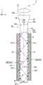
图2是光源装置的俯视图。FIG. 2 is a plan view of the light source device.
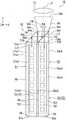
图3是光源装置的侧视图。FIG. 3 is a side view of the light source device.
图4是沿着图2的IV-IV线的剖视图。FIG. 4 is a cross-sectional view taken along line IV-IV of FIG. 2 .
图5是第2实施方式的光源装置的侧视图。5 is a side view of a light source device according to a second embodiment.
图6是第3实施方式的光源装置的俯视图。6 is a plan view of a light source device according to a third embodiment.
图7是第3实施方式的投影仪的概略结构图。7 is a schematic configuration diagram of a projector according to a third embodiment.
标号说明Label description
1、10:投影仪;2、16:光源装置;4B、4G、4R、13:光调制装置;6、14:投射光学装置;51:导光棒(导光体);51a:第1端面;51b:第2端面;51c1:第1侧面;51c3:第3侧面;51c5:第5侧面;51c7:第7侧面;53:光合成部;54:棱镜;55:分色棱镜;58:波长转换棒(波长转换部);58a:第3端面;58b:第4端面;58c2:第2侧面;58c4:第4侧面;58c6:第6侧面;58c8:第8侧面;62、72:光源部;622:发光二极管光源;732:第一LED光源;742:第二LED光源;L1:第1光;L11:第1光;L12:激励光;L2:第2光;N1、N2:长度方向。1, 10: projector; 2, 16: light source device; 4B, 4G, 4R, 13: light modulation device; 6, 14: projection optical device; 51: light guide rod (light guide body); 51a: first end face ;51b: 2nd side; 51c1: 1st side; 51c3: 3rd side; 51c5: 5th side; 51c7: 7th side; 53: Light combining part; 54: Prism; 55: Dichroic prism; 58: Wavelength conversion Rod (wavelength conversion part); 58a: 3rd end face; 58b: 4th end face; 58c2: 2nd side face; 58c4: 4th side face; 58c6: 6th side face; 58c8: 8th side face; 62, 72: Light source part; 622: light emitting diode light source; 732: first LED light source; 742: second LED light source; L1: first light; L11: first light; L12: excitation light; L2: second light; N1, N2: length direction.
具体实施方式Detailed ways
[第1实施方式][First Embodiment]
下面,使用图1~图4对本发明的第1实施方式进行说明。Next, a first embodiment of the present invention will be described with reference to FIGS. 1 to 4 .
本实施方式的投影仪是使用液晶面板作为光调制装置的液晶投影仪的一例。The projector of the present embodiment is an example of a liquid crystal projector using a liquid crystal panel as a light modulation device.
图1是第1实施方式的投影仪1的概略结构图。FIG. 1 is a schematic configuration diagram of the projector 1 according to the first embodiment.
另外,在以下的各附图中,为了容易观察各结构要素,有时根据结构要素的不同而以不同尺寸的比例尺进行示出。In addition, in each of the following drawings, in order to facilitate the observation of each component, the scale may be shown on a different scale depending on the component.
第1实施方式的投影仪1是在屏幕(被投射面)SCR上投射彩色图像的投射型图像显示装置。投影仪1使用与红色光LR、绿色光LG、蓝色光LB的各色光对应的3个光调制装置。The projector 1 according to the first embodiment is a projection-type image display device that projects a color image on a screen (projected surface) SCR. The projector 1 uses three light modulation devices corresponding to the respective colors of red light LR, green light LG, and blue light LB.
如图1所示,投影仪1具有光源装置2、均匀照明光学系统40、颜色分离光学系统3、光调制装置4R、光调制装置4G、光调制装置4B、合成光学系统5和投射光学装置6。As shown in FIG. 1 , the projector 1 has a
光源装置2朝向均匀照明光学系统40射出照明光WL。光源装置2的详细结构在后面详细说明。The
均匀照明光学系统40具有积分光学系统31、偏振转换元件32和重叠光学系统33。积分光学系统31具有第1透镜阵列31a和第2透镜阵列31b。均匀照明光学系统40使从光源装置2射出的照明光WL的强度分布在作为被照明区域的光调制装置4R、光调制装置4G和光调制装置4B中分别均匀化。从均匀照明光学系统40射出的照明光WL入射到颜色分离光学系统3。The uniform illumination
颜色分离光学系统3将白色的照明光WL分离成红色光LR、绿色光LG和蓝色光LB。颜色分离光学系统3具有第1分色镜7a、第2分色镜7b、第1反射镜8a、第2反射镜8b、第3反射镜8c、第1中继透镜9a、第2中继透镜9b。The color separation
第1分色镜7a将来自光源装置2的照明光WL分离成红色光LR和其他光(绿色光LG和蓝色光LB)。第1分色镜7a使分离后的红色光LR透过,并且反射其他光(绿色光LG和蓝色光LB)。另一方面,第2分色镜7b将其他光分离成绿色光LG和蓝色光LB。第2分色镜7b反射分离后的绿色光LG,使蓝色光LB透过。The first
第1反射镜8a配置在红色光LR的光路中,使透过第1分色镜7a的红色光LR朝向光调制装置4R反射。另一方面,第2反射镜8b和第3反射镜8c配置在蓝色光LB的光路中,使透过第2分色镜7b的蓝色光LB朝向光调制装置4B反射。此外,第2分色镜7b使绿色光LG朝向光调制装置4G反射。The first reflecting
第1中继透镜9a和第2中继透镜9b配置在蓝色光LB的光路中的第2分色镜7b的光射出侧。第1中继透镜9a和第2中继透镜9b对由于蓝色光LB的光路长度比红色光LR、绿色光LG的光路长度长而引起的蓝色光LB的照明分布差异进行修正。The
光调制装置4R根据图像信息对红色光LR进行调制,形成与红色光LR对应的图像光。光调制装置4G根据图像信息对绿色光LG进行调制,形成与绿色光LG对应的图像光。光调制装置4B根据图像信息对蓝色光LB进行调制,形成与蓝色光LB对应的图像光。The
光调制装置4R、光调制装置4G和光调制装置4B例如使用透过型的液晶面板。此外,构成为在液晶面板的入射侧和射出侧分别配置有偏振片(未图示),仅使特定方向的线偏振光通过。As the
在光调制装置4R、光调制装置4G和光调制装置4B的入射侧分别配置有场透镜10R、场透镜10G、场透镜10B。场透镜10R、场透镜10G和场透镜10B对入射到光调制装置4R的红色光LR、入射到光调制装置4G的绿色光LG、入射到光调制装置4B的蓝色光LB的各主光线进行平行化。A
从光调制装置4R、光调制装置4G和光调制装置4B射出的图像光入射到合成光学系统5,由此,合成光学系统5对与红色光LR、绿色光LG、蓝色光LB对应的图像光进行合成,使合成后的图像光朝向投射光学装置6射出。合成光学系统5例如使用十字分色棱镜。The image light emitted from the
投射光学装置6由多个投射透镜构成。投射光学装置6将由合成光学系统5合成的图像光放大并朝向屏幕SCR投射。由此,在屏幕SCR上显示图像。The projection optical device 6 is composed of a plurality of projection lenses. The projection optical device 6 amplifies the image light synthesized by the synthesis optical system 5 and projects it toward the screen SCR. Thereby, an image is displayed on the screen SCR.
以下,对光源装置2进行说明。Hereinafter, the
图2是示出光源装置2的概略结构的俯视图。图3是从导光棒51侧观察到的光源装置2的侧视图。图4是沿着图2的IV-IV线的光源装置2的剖视图。FIG. 2 is a plan view showing a schematic configuration of the
如图2及图3所示,光源装置2具有导光棒51(导光体)、波长转换棒58(波长转换部)、光源部62、透光性部件65、光合成部53、角度转换元件56以及准直透镜57。As shown in FIGS. 2 and 3 , the
导光棒51具备具有6个面的四棱柱状的形状。六个面包含相互对置的两个端面51a、51b和与两个端面51a、51b交叉的四个侧面51c1、51c3、51c5、51c7。The
在以下的说明中,将端面51a称为第1端面51a,将端面51b称为第2端面51b。位于远离后述的光合成部53的一侧的导光棒51的端面为第1端面51a,与第1端面51a对置并且从导光棒51射出光的一侧的端面为第2端面51b。另外,将侧面51c1称为第1侧面51c1,将侧面51c3称为第3侧面51c3,将侧面51c5称为第5侧面51c5,将侧面51c7称为第7侧面51c7。另外,将第1端面51a与第2端面51b对置的方向定义为导光棒51的长度方向N1。In the following description, the
同样地,波长转换棒58具备具有6个面的四棱柱状的形状。六个面包含相互对置的两个端面58a、58b以及与两个端面58a、58b交叉的四个侧面58c2、58c4、58c6、58c8。Similarly, the
在以下的说明中,将端面58a称为第3端面58a,将端面58b称为第4端面58b。位于与导光棒51的第1端面51a同一侧的波长转换棒58的端面为第3端面58a,与第3端面58a对置并且从波长转换棒58射出光的一侧的端面为第4端面58b。另外,将侧面58c2称为第2侧面58c2,将侧面58c4称为第4侧面58c4,将侧面58c6称为第6侧面58c6,将侧面58c8称为第8侧面58c8。另外,将第3端面58a与第4端面58b对置的方向定义为波长转换棒58的长度方向N2。另外,将穿过波长转换棒58的第3端面58a的中心和第4端面58b的中心的轴定义为光源装置2的光轴J1。来自光源装置2的合成光LW沿着光轴J1射出。In the following description, the
在本实施方式中,导光棒51与波长转换棒58具有大致相同的尺寸。导光棒51的长度方向N1的尺寸A比导光棒51的短边方向(与长度方向N1垂直的方向)的尺寸B长。例如尺寸A是尺寸B的十倍~几十倍左右。关于波长转换棒58,也与导光棒51同样。In this embodiment, the
导光棒51和波长转换棒58以导光棒51的第5侧面51c5与波长转换棒58的第6侧面58c6对置的方式隔着间隔相互并列配置。另外,在本说明书中,“导光棒与波长转换棒并列配置”的记载是指导光棒与波长转换棒以相互的侧面彼此对置的状态配置。The
在本实施方式的情况下,导光棒51和波长转换棒58以导光棒51的长度方向N1与波长转换棒58的长度方向N2平行的方式相邻配置。通过该配置,能够减小光源装置2的宽度(与光轴J1垂直的方向的尺寸)。但是,导光棒51的长度方向N1与波长转换棒58的长度方向N2不是必须平行,也可以相对于平行而倾斜。In the case of this embodiment, the
如图3所示,光源部62具有第1光源62A和第2光源62B。如图2所示,第1光源62A设置在与导光棒51和波长转换棒58对置的位置。更具体而言,第1光源62A设置在与导光棒51的第1侧面51c1和波长转换棒58的第2侧面58c2对置的位置。即,光源部62设置在与导光棒51和波长转换棒58对置的位置。As shown in FIG. 3 , the
虽然在图2中未图示,但第2光源62B也与第1光源62A同样地设置在与导光棒51和波长转换棒58对置的位置。更具体而言,第2光源62B设置在与导光棒51的第3侧面51c3和波长转换棒58的第4侧面58c4对置的位置。Although not shown in FIG. 2 , the second
第1光源62A和第2光源62B具有相同的结构,它们具有:基板621;多个发光二极管光源622(LED光源),它们安装在与导光棒51和波长转换棒58对置的基板621的一个面上。在本实施方式中,各光源62A、62B具有5个LED光源622,但LED光源622的个数没有特别限定。各LED光源622射出第1波段的第1光L1。第1波段例如是400nm~480nm的蓝色波段,峰值波长例如是445nm。另外,各光源62A、62B除了基板621和LED光源622之外,还可以具有导光板、扩散板、透镜等其他光学部件。The first
多个LED光源622分别与导光棒51的第1侧面51c1和第3侧面51c3、以及波长转换棒58的第2侧面58c2和第4侧面58c4对置地设置。即,从导光棒51的第1侧面51c1的法线方向观察时,构成第1光源62A的多个LED光源622设置在与导光棒51的第1侧面51c1和波长转换棒58的第2侧面58c2重叠的位置。另外,从导光棒51的第3侧面51c3的法线方向观察时,构成第2光源62B的多个LED光源622设置在与导光棒51的第3侧面51c3和波长转换棒58的第4侧面58c4重叠的位置。The plurality of LED
换言之,构成第1光源62A的多个LED光源622与导光棒51的第1侧面51c1和波长转换棒58的第2侧面58c2对置地设置。构成第2光源62B的多个LED光源622与导光棒51的第3侧面51c3和波长转换棒58的第4侧面58c4对置地设置。构成第1光源62A和第2光源62B的多个LED光源622沿着各棒51、58的长度方向N1、N2隔开间隔地排列。In other words, the plurality of LED
如图2所示,LED光源622的宽度D(与光轴J1垂直的方向的尺寸)小于导光棒51的宽度B与波长转换棒58的宽度C的合计,即小于从导光棒51的第7侧面51c7到波长转换棒58的第8侧面58c8的距离。但是,LED光源622的宽度D也可以等于导光棒51的宽度B与波长转换棒58的宽度C的合计,还可以大于导光棒51的宽度B与波长转换棒58的宽度C的合计。As shown in FIG. 2 , the width D of the LED light source 622 (the dimension in the direction perpendicular to the optical axis J1 ) is smaller than the sum of the width B of the
另外,在本实施方式中,在全部LED光源622中,LED光源622与导光棒51相互对置的区域的面积大致等于LED光源622与波长转换棒58相互对置的区域的面积。即,LED光源622的宽度D方向的中心线位于导光棒51与波长转换棒58之间。In this embodiment, among all the
如图4所示,从LED光源622射出的光L1中的一部分光L11在导光棒51的内部传播后,从导光棒51射出,作为构成照明光的一部分的蓝色光发挥功能。另一部分光L12在入射到波长转换棒58后,作为激励波长转换棒58所包含的荧光体的激励光发挥功能。在以下的说明中,将一部分光L11称为第1光L11,将另一部分光L12称为激励光L12。因此,第1光L11和激励光L12只是所入射的棒不同,是从一个LED光源622射出的相同波段的光。As shown in FIG. 4 , part of the light L11 of the light L1 emitted from the LED
这样,入射到导光棒51的第1光L11的功能和入射到波长转换棒58的激励光L12的功能相互不同。因此,LED光源622需要射出能够发挥任意功能的波长的光。In this way, the function of the first light L11 incident on the
导光棒51例如由玻璃等透光性材料构成。导光棒51入射有从各光源62A、62B射出的第1光L11,使第1光L11在内部传播。The
导光棒51具有设置在四个侧面51c1、51c3、51c5、51c7中的不与光源62A、62B对置的第5侧面51c5和第7侧面51c7上的反射镜64。此外,导光棒51具有设置在第1端面51a上的反射镜64。这些反射镜64由在构成导光棒51的透光性材料的表面形成的电介质多层膜、金属膜等材料构成。从抑制光损失的观点出发,优选反射镜64由电介质多层膜构成。The
波长转换棒58包含被从光源部62射出的激励光L12激励而发出第2光L2的荧光体。在本实施方式中,荧光体由陶瓷荧光体(多晶荧光体)构成。第2光L2的波段例如是490nm~750nm的黄色波段。即,第2光L2是黄色荧光。波长转换棒58也可以不由多晶荧光体而由单晶荧光体构成。或者,波长转换棒58也可以由荧光玻璃构成。或者,波长转换棒58也可以由将多个荧光体粒子分散到由玻璃或树脂构成的粘合剂中而得到的材料构成。The
具体而言,波长转换棒58例如由钇铝石榴石(YAG)系荧光体构成。当列举含有作为活化剂的铈(Ce)的YAG:Ce为例时,作为波长转换棒58的材料,能够使用:混合包含Y2O3、Al2O3、CeO3等结构元素在内的原料粉末并使它们进行固相反应而得的材料;通过共沉淀法、溶胶凝胶法等湿法得到的Y-Al-O非晶粒子;通过喷雾干燥法、火焰热分解法、热等离子体法等气相法得到的YAG粒子等。Specifically, the
如图2所示,波长转换棒58具有设置在第3端面58a上的反射镜63。反射镜63由电介质多层膜、金属膜等材料构成。As shown in FIG. 2 , the
如图3及图4所示,透光性部件65设置在各光源62A、62B与导光棒51之间。更详细地说,透光性部件65在第1光源62A的LED光源622与导光棒51的第1侧面51c1之间、以及第2光源62B的LED光源622与导光棒51的第3侧面51c3之间,以覆盖LED光源622的光射出面的方式设置。透光性部件65与光源部62和导光棒51接触。As shown in FIGS. 3 and 4 , the
透光性部件65例如由硅酮树脂等透明树脂、玻璃熔块等构成。在透光性部件65由透明树脂构成的情况下,能够容易地制造透光性部件65。另外,优选透光性部件65具有光透过性和耐热性。透光性部件65还作为固定各光源62A、62B和导光棒51的粘接材料发挥功能。The
优选透光性部件65的折射率与导光棒51的折射率相等。根据该结构,第1光L11以规定的角度入射到导光棒51,而不会产生第1光L11从透光性部件65入射到导光棒51时的无用的折射。由此,能够减少从导光棒51的侧面射出的第1光L11的量,能够提高第1光L11的利用效率。另外,本发明中的“透光性部件的折射率和导光体的折射率相等”是包含以下情况的概念:透光性部件和导光体具有仅产生光利用效率的降低不影响性能程度的微小折射的折射率差。The refractive index of the
如图4所示,优选在各光源62A、62B与波长转换棒58之间不设置透光性部件65。只要当激励光L12入射到波长转换棒58时,激励光L12到达荧光体即可,入射到波长转换棒58时的折射不会成为大的问题,因此,在各光源62A、62B与波长转换棒58之间可以不设置透光性部件65。但是,在各光源62A、62B与波长转换棒58之间也可以设置透光性部件65。As shown in FIG. 4 , it is preferable that the
如图2所示,光合成部53配置于与导光棒51的第2端面51b和波长转换棒58的第4端面58b对置的位置。光合成部53对从导光棒51射出的第1光L11和从波长转换棒58射出的第2光L2进行合成。光合成部53具有与导光棒51的第2端面51b对置的棱镜54以及与波长转换棒58的第4端面58b对置的分色棱镜55。As shown in FIG. 2 , the
棱镜54与导光棒51的第2端面51b接触设置。棱镜54由具有等腰直角三角形的截面的三棱柱状棱镜构成,具有光入射端面54a、反射面54c和光射出端面54b。棱镜54具有使所入射的第1光L11的光路弯曲90°而射出的功能。即,棱镜54使从导光棒51的第2端面51b射出的第1光L11在反射面54c反射从而使光路弯曲并从光射出端面54b射出。The
分色棱镜55与波长转换棒58的第4端面58b和棱镜54的光射出端面54b对置设置。分色棱镜55具有在棱镜主体的内部设置有分色镜551的结构。分色棱镜55具有立方体状的形状,具有光入射端面55a、光入射端面55b以及光射出端面55c。分色镜551具有反射蓝色波段的光而使黄色波段的光透过的特性。因此,从棱镜54射出的第1光L11被分色镜551反射而朝向光射出端面55c行进。另一方面,从波长转换棒58的第4端面58b射出的第2光L2透过分色镜551而朝向光射出端面55c行进。The
这样,分色棱镜55对从导光棒51的第2端面51b射出的蓝色的第1光L11和从波长转换棒58的第4端面58b射出的黄色的第2光L2进行合成。然后,由蓝色的第1光L11和黄色的第2光L2构成的白色的合成光LW从分色棱镜55射出。这样,在光合成部53中,通过对第1光L11和第2光L2进行合成,从光合成部53射出白色的合成光LW。In this way, the
角度转换元件56设置于分色棱镜55的光射出端面55c的光射出侧。角度转换元件56由具有供合成光LW入射的光入射端面56a和射出合成光LW的光射出端面56b的锥形棒构成。角度转换元件56具有四棱锥台状的形状,与光轴J1垂直的截面面积沿着合成光LW的行进方向扩大,光射出端面56b的面积比光入射端面56a的面积大。由此,合成光LW在角度转换元件56的内部行进的期间内,每当在侧面56c发生全反射时,朝与光轴J1平行的方向改变角度。这样,角度转换元件56使光射出端面56b处的合成光LW的扩散角比光入射端面56a处的合成光LW的扩散角小。The
角度转换元件56以光入射端面56a与分色棱镜55的光射出端面55c对置的方式固定于分色棱镜55。即,角度转换元件56和分色棱镜55经由光学粘接剂(省略图示)而接触,在角度转换元件56与分色棱镜55之间不设置空隙(空气层)。另外,角度转换元件56例如也可以通过任意的支承部件,以与分色棱镜55直接接触的方式进行固定。总之,优选在角度转换元件56与分色棱镜55之间不设置空隙。优选角度转换元件56的折射率和分色棱镜55的折射率尽可能一致。The
另外,作为角度转换元件56,也可以代替锥形棒而使用复合抛物面型聚光器(Compound Parabolic Concentrator,CPC)。在使用CPC作为角度转换元件56的情况下,也得到与使用锥形棒的情况相同的效果。In addition, as the
准直透镜57设置于角度转换元件56的光射出端面56b的光射出侧。准直透镜57对从角度转换元件56射出的合成光LW进行平行化。即,由角度转换元件56对角度分布进行转换后的合成光LW的平行度通过准直透镜57而进一步提高。准直透镜57由凸透镜构成。另外,在仅通过角度转换元件56就能够得到充分的平行度的情况下,不是必须设置准直透镜57。The
以下,对上述结构的光源装置2的作用进行说明。Hereinafter, the operation of the
如图4所示,第1光L11从LED光源622射出后,透过透光性部件65,从第1侧面51c1入射到导光棒51。入射到导光棒51的第1光L11以临界角以上的入射角到达任意一个侧面51c1、51c3、51c5、51c7。这样的第1光L11在被该侧面反射后,反复被侧面反射,并且如图3所示,在导光棒51的内部传播,朝向第1端面51a或第2端面51b行进。朝向第2端面51b行进的第1光L11从第2端面51b射出后,入射到棱镜54。另一方面,朝向第1端面51a行进的第1光L11被设置在第1端面51a上的反射镜64反射后,朝向第2端面51b行进。As shown in FIG. 4 , after being emitted from the LED
然后,如图2所示,从导光棒51的第2端面51b射出的第1光L11被棱镜54的反射面54c反射,而改变了行进方向并入射到分色棱镜55。另外,优选以使棱镜54和分色棱镜55不直接接触的方式在棱镜54与分色棱镜55之间设置间隙(空气层)。通过在棱镜54与分色棱镜55之间设置有间隙,抑制了在棱镜54与分色棱镜55的界面附近行进的第1光L11中的以小于临界角的入射角入射到界面的光泄漏到棱镜54或分色棱镜55的外部,能够提高光利用效率。Then, as shown in FIG. 2 , the first light L11 emitted from the
另一方面,如图4所示,激励光L12入射到波长转换棒58。此时,波长转换棒58所包含的荧光体被激励光L12激励,而从任意的发光点P1发出第2光L2。第2光L2从任意的发光点P1向所有方向行进,但向侧面58c2、58c4、58c6、58c8行进的第2光L2如图2所示,被侧面58c2、58c4、58c6、58c8反复全反射,并且朝向第3端面58a或第4端面58b行进。朝向第4端面58b行进的第2光L2从第4端面58b射出后,入射到分色棱镜55。另一方面,朝向第3端面58a行进的第2光L2被设置在第3端面58a上的反射镜63反射后,朝向第4端面58b行进。On the other hand, as shown in FIG. 4 , the excitation light L12 is incident on the
入射到分色棱镜55的第1光L11被分色镜551反射。另一方面,入射到分色棱镜55的第2光L2透过分色镜551。其结果,对蓝色的第1光L11和黄色的第2光L2进行合成,从分色棱镜55的光射出端面55c射出白色的合成光LW。从分色棱镜55射出的合成光LW由角度转换元件56和准直透镜57进行平行化后,从光源装置2射出。如图1所示,从光源装置2射出的合成光LW(照明光WL)朝向积分光学系统31行进。The first light L11 incident on the
在本实施方式的光源装置2中,射出蓝色的第1光L11的导光棒51与射出黄色的第2光L2的波长转换棒58相互并列配置,在导光棒51的第2端面51b和波长转换棒58的第4端面58b上配置有光合成部53,光源部62与导光棒51的第1侧面51c1和波长转换棒58的第2侧面58c2对置地设置。由此,能够实现可射出白色光的小型的光源装置2。In the
本实施方式的光源装置2具有通过导光棒51将从光源部62射出的蓝色的光L11引导至光合成部53的结构。因此,光源装置2无需额外使用例如紫外LED和蓝色荧光体的组合这样的能够发出蓝色光的荧光体光源,能够通过简单的结构高效地得到蓝色光。The
LED光源622示出朗伯配光,因此特别是在导光棒51的宽度(图2中的尺寸B)比LED光源622的宽度(图2中的尺寸D)小的情况下,有时难以使从LED光源622射出的第1光L11高效地入射到导光棒51的端面。因此,在使用LED光源622的情况下,如本实施方式那样,采用将LED光源622与导光棒51的侧面对置地配置、使第1光L11从导光棒51的侧面入射的结构是合理的。Since the LED
但是,即使是使LED光源622与导光棒51的侧面对置的结构,在LED光源622的宽度比导光棒51的宽度大的情况下,LED光源622的光射出面有时也从导光棒51的侧面向外侧露出。在这种情况下,从LED光源622射出的第1光L11的一部分不入射到导光棒51,因此存在第1光L11的利用效率降低的问题。通常,由于发光效率高的LED光源的尺寸大,因此,存在想要使用尺寸大的LED光源的要求。However, even in a configuration in which the
针对该问题,在本实施方式的光源装置2中,由于LED光源622的宽度(图2中的尺寸D)比导光棒51的宽度(图2中的尺寸B)与波长转换棒的宽度(图2中的尺寸C)的合计小,因此,LED光源622的光射出面不会从导光棒51和波长转换棒58的侧面向外侧露出。由此,能够使从LED光源622射出的第1光L11充分地入射到导光棒51和波长转换棒58,能够提高第1光L11的利用效率。另外,由于各LED光源622被导光棒51和波长转换棒58共用,因此不用过度增加LED光源622的数量,就能够实现光源装置2的小型化、低成本化以及低光学扩展量(Etendue)化。In order to solve this problem, in the
在本实施方式的光源装置2中,由于在LED光源622与导光棒51之间夹设有透光性部件65,因此,从LED光源622射出的第1光L11在透光性部件65的内部传播而入射到导光棒51。根据该结构,与LED光源622和导光棒51分开配置并且在它们之间存在空气的情况相比,能够抑制无用的折射和反射,能够增加入射到导光棒51的第1光L11的光量。特别是在本实施方式的情况下,由于透光性部件65的折射率与导光棒51的折射率相等,因此能够最大限度地增加入射到导光棒51的第1光L11的光量。由此,能够提高第1光L11的利用效率。特别是在本实施方式的情况下,由于透光性部件65与光源部62和导光棒51接触,因此能够抑制第1光L11的损失,能够进一步提高第1光L11的利用效率。In the
在本实施方式的光源装置2中,在分色棱镜55的光射出侧设置有角度转换元件56,因此,能够对从分色棱镜55射出的合成光LW进行平行化。进而,在角度转换元件56的光射出侧设置有准直透镜57,因此,能够进一步提高合成光LW的平行度。由此,能够提高光源装置2的后级的光学系统中的光利用效率。In the
本实施方式的投影仪1具有上述光源装置2,因此,实现了小型化,并且光利用效率优异。The projector 1 of the present embodiment has the above-described
[第2实施方式][Second Embodiment]
以下,使用图5对本发明的第2实施方式进行说明。Hereinafter, a second embodiment of the present invention will be described with reference to FIG. 5 .
第2实施方式的光源装置的基本结构与第1实施方式相同,光源部的结构与第1实施方式不同。因此,省略光源装置的整体结构的说明。The basic configuration of the light source device of the second embodiment is the same as that of the first embodiment, and the configuration of the light source unit is different from that of the first embodiment. Therefore, the description of the overall structure of the light source device is omitted.
图5是示出第2实施方式的光源装置的概略结构的侧视图。5 is a side view showing a schematic configuration of a light source device according to a second embodiment.
在图5中,对与图2相同的结构要素标注相同的标号并省略说明。In FIG. 5 , the same components as those in FIG. 2 are denoted by the same reference numerals and descriptions thereof are omitted.
如图5所示,光源装置16具有导光棒51(导光体)、波长转换棒58(波长转换部)、光源部62、透光性部件65、光合成部53、角度转换元件56以及准直透镜57。As shown in FIG. 5 , the
光源部62具有第1光源62A。第1光源62A设置在与导光棒51的第1侧面51c1和波长转换棒58的第2侧面58c2对置的位置。光源部62与第1实施方式不同,不具有设置在与导光棒51的第3侧面51c3和波长转换棒58的第4侧面58c4对置的位置上的第2光源62B。The
在导光棒51的第3侧面51c3上设置有反射镜64。反射镜64由在构成导光棒51的透光性材料的表面形成的电介质多层膜、金属膜等材料构成。从抑制光损失的观点出发,优选反射镜64由电介质多层膜构成。A
光源装置16的其他结构与第1实施方式相同。The other configuration of the
在本实施方式中,也得到能够实现小型且低光学扩展量的光源装置16这样的与第1实施方式相同的效果。Also in the present embodiment, the same effect as that of the first embodiment can be obtained in that a small and low etendue
本实施方式的光源部62仅具有与导光棒51的第1侧面51c1对置的第1光源62A,但由于在与第1侧面51c1相反的一侧的第3侧面51c3上设置有反射镜64,因此,抑制了从第1侧面51c1入射到导光棒51的第1光L11从第3侧面51c3向外部射出。由此,能够提高第1光L11的提取效率。The
[第3实施方式][Third Embodiment]
下面,使用图6对本发明的第3实施方式进行说明。Next, a third embodiment of the present invention will be described with reference to FIG. 6 .
第3实施方式的光源装置的基本结构与第1实施方式相同,光源部的结构与第1实施方式不同。因此,省略光源装置的整体结构的说明。The basic configuration of the light source device of the third embodiment is the same as that of the first embodiment, and the configuration of the light source unit is different from that of the first embodiment. Therefore, the description of the overall structure of the light source device is omitted.
图6是示出第3实施方式的光源装置18的概略结构的俯视图。FIG. 6 is a plan view showing a schematic configuration of a
在图6中,对与图2相同的结构要素标注相同的标号并省略说明。In FIG. 6 , the same components as those in FIG. 2 are denoted by the same reference numerals and descriptions thereof are omitted.
如图6所示,光源装置18具有导光棒51(导光体)、波长转换棒58(波长转换部)、光源部72、透光性部件65、光合成部53、角度转换元件56以及准直透镜57。As shown in FIG. 6 , the
光源部72具有导光棒用光源73和波长转换棒用光源74。导光棒用光源73和波长转换棒用光源74具有同样的结构,它们具有:基板621;以及多个LED光源732、742,它们安装在基板621的一个面上。具体而言,导光棒用光源73具有沿导光棒51的长度方向N1隔开间隔地排列的多个第一LED光源732。多个第一LED光源732分别向导光棒51射出第1光L11。波长转换棒用光源74具有沿波长转换棒58的长度方向N2隔开间隔地排列的多个第二LED光源742。多个第二LED光源742分别向波长转换棒58射出激励光L12。The
从第一LED光源732射出的第1光L11在导光棒51的内部传播后,从导光棒51射出,作为构成照明光的一部分的蓝色光发挥功能。另一方面,从第二LED光源742射出的激励光L12入射到波长转换棒58后,激励波长转换棒58的荧光体。这样,从第一LED光源732射出的第1光L11的功能与从第二LED光源742射出的激励光L12的功能相互不同。因此,第一LED光源732和第二LED光源742可以射出作为蓝色光或激励光而分别最优化后的相互不同的波长的光,也可以射出能共用于任意功能的相同波长的光。The first light L11 emitted from the first
光源装置18的其他结构与第1实施方式相同。The other configuration of the
在本实施方式中,也得到能够实现小型且低光学扩展量的光源装置18这样的与第1实施方式相同的效果。Also in the present embodiment, the same effect as that of the first embodiment can be obtained in that a small and low etendue
另外,从导光棒51射出蓝色的第1光L11,从波长转换棒58射出黄色的第2光L2,将它们合成而得到白色的合成光LW,因此,通过调整第1光L11光量与第2光L2的光量的平衡,能够调整白色光的白平衡。作为具体的白平衡的调整方法,例如可以采用如下结构:在光源装置18中预先具有检测第1光L11和第2光L2各自的光量的传感器,根据传感器检测出的各光量相对于标准值的偏差,来适当调整向第一LED光源732和第二LED光源742供给的电力。另外,作为设计阶段的白平衡的调整方法,可以调整第一LED光源732或第二LED光源742的数量,也可以调整导光棒51或波长转换棒58的长度或粗细。In addition, the blue first light L11 is emitted from the
[第4实施方式][4th Embodiment]
下面,使用图7对本发明的第4实施方式进行说明。Next, a fourth embodiment of the present invention will be described with reference to FIG. 7 .
在第1实施方式中,举出液晶投影仪的例子,而在第4实施方式中,列举具有微镜型的光调制装置的投影仪的一例进行说明。In the first embodiment, an example of a liquid crystal projector is given, and in the fourth embodiment, an example of a projector having a micromirror-type light modulation device is given and described.
如图7所示,第4实施方式的投影仪10具有照明装置11、导光光学系统12、微镜型的光调制装置13以及投射光学装置14。照明装置11具有光源装置2、色轮23以及拾取光学系统21。As shown in FIG. 7 , the
在第4实施方式中,使用第1实施方式的光源装置2作为光源装置2。但是,作为光源装置2,可以使用第2实施方式的光源装置16,也可以使用第3实施方式的光源装置18。因此,在第4实施方式中,省略光源装置2的说明。In the fourth embodiment, the
色轮23具有在可旋转的基板上沿着旋转轴的周向设置有红色、绿色、蓝色这3色的滤色器的结构。从光源装置2射出的白色的合成光LW通过高速旋转的色轮23,由此,以分时的方式从色轮23射出红色光LR、绿色光LG和蓝色光LB。The
拾取光学系统21由第1透镜211和第2透镜212构成。第1透镜211和第2透镜212分别由凸透镜构成。从色轮23射出的红色光LR、绿色光LG和蓝色光LB通过拾取光学系统21传递到导光光学系统12。The pickup
导光光学系统12由反射镜构成。导光光学系统12使从光源装置2射出的红色光LR、绿色光LG和蓝色光LB反射,并以分时的方式入射到光调制装置13。The light guide
作为微镜型的光调制装置13,例如使用DMD(Digital Micromirror Device:数字微镜器件)。DMD具有呈矩阵状排列有多个微镜的结构。DMD通过切换多个微镜的倾斜方向,而使入射光的反射方向在向投射光学装置14入射的方向与不向投射光学装置14入射的方向之间高速切换。这样,光调制装置13依次对从光源装置2射出的红色光LR、绿色光LG和蓝色光LB进行调制,生成绿色图像、红色图像和蓝色图像。As the
投射光学装置14向屏幕投射绿色图像、红色图像和蓝色图像。投射光学装置14例如由多个投射透镜构成。
本实施方式的投影仪10具有第1实施方式的光源装置2,因此,实现小型化,并且光利用效率优异。The
另外,本发明的技术范围不限于上述实施方式,能够在不脱离本发明主旨的范围内施加各种变更。In addition, the technical scope of the present invention is not limited to the above-described embodiments, and various modifications can be added without departing from the gist of the present invention.
例如在上述实施方式的光源装置中,列举了透光性部件的折射率与导光体的折射率相等的例子,但透光性部件的折射率和导光体的折射率也可以相互不同。For example, in the light source device of the above-described embodiment, the refractive index of the translucent member and the refractive index of the light guide body are equal to each other, but the refractive index of the translucent member and the refractive index of the light guide body may be different from each other.
当在LED光源与导光棒之间存在空气的情况下,第1光入射到导光棒时发生折射,向导光棒的侧面入射的入射角小于临界角的光增多,因此,存在从导光棒射出的光的量增加的问题。针对该问题,当在LED光源与导光棒之间存在透光性部件的情况下,与存在空气的情况相比,第1光的折射角变小,因此,向导光棒的侧面入射的入射角大于临界角的光增多,在导光棒中传播的第1光的量增加。这样,即使透光性部件的折射率与导光体的折射率不同,与未设置透光性部件的情况相比,也得到了能够提高第1光L11的利用效率的效果。When there is air between the LED light source and the light guide rod, the first light is refracted when incident on the light guide rod, and the incident angle of the incident angle smaller than the critical angle of the light guide rod increases. The problem of increasing the amount of light emitted by the rod. In order to solve this problem, when there is a translucent member between the LED light source and the light guide rod, the refraction angle of the first light becomes smaller than that in the case where there is air. Therefore, the incident light incident on the side of the light guide rod As the light with an angle larger than the critical angle increases, the amount of the first light propagating in the light guide rod increases. In this way, even if the refractive index of the translucent member is different from the refractive index of the light guide, the effect of improving the utilization efficiency of the first light L11 is obtained compared with the case where the translucent member is not provided.
在上述实施方式中,列举了LED光源与导光棒的侧面对置地配置、第1光从导光棒的侧面入射的结构的例子,但本发明的光源装置也可以具有如下结构:LED光源与导光棒的端面对置地配置,第1光经由透光性部件从导光棒的端面入射。In the above-described embodiments, the LED light source and the side surface of the light guide rod are arranged to face the side surface of the light guide rod, and the first light is incident from the side surface of the light guide rod. The end faces of the light guide rod are arranged to face each other, and the first light is incident from the end faces of the light guide rod through the translucent member.
在上述实施方式中,列举了波长转换棒包含射出黄色荧光的荧光体的例子,但是,波长转换棒也可以包含由射出绿色荧光的荧光体和射出红色荧光的荧光体构成的2种荧光体。在该情况下,2种荧光体可以在波长转换棒的内部均匀地混合存在,也可以划分区域而不均匀地存在。In the above-described embodiment, the wavelength conversion rod includes the phosphor emitting yellow fluorescence. However, the wavelength conversion rod may include two types of phosphors including a phosphor emitting green fluorescence and a phosphor emitting red fluorescence. In this case, the two types of phosphors may be uniformly mixed in the inside of the wavelength conversion rod, or may be divided into regions and not uniformly present.
在上述实施方式中,举出了射出白色光的光源装置的例子,但是,本发明还能够应用于射出白色以外的色光的光源装置。例如,也可以是如下的光源装置:具有射出蓝色光的导光棒和射出红色光的波长转换棒,从而射出通过合成蓝色光和红色光而生成的品红色的光。在该情况下,根据本发明,也能够实现射出品红色的光的小型且低光学扩展量的光源装置。进而,也可以使用该光源装置和射出绿色光的光源装置构成射出白色光的光源装置。In the above-described embodiments, the example of a light source device that emits white light is given, but the present invention can also be applied to a light source device that emits color light other than white. For example, a light source device including a light guide rod that emits blue light and a wavelength conversion rod that emits red light may emit magenta light generated by combining blue light and red light. Even in this case, according to the present invention, it is possible to realize a small-sized light source device with low etendue that emits magenta light. Furthermore, a light source device that emits white light may be configured using this light source device and a light source device that emits green light.
在上述实施方式中,提示了使用棱镜和分色棱镜作为光合成部的结构例,但是,还能应用可进行光合成的其他光学部件。例如也可以代替棱镜而使用反射镜。此外,也可以代替分色棱镜而使用在内部具有光散射构造的散射体。作为散射体的例子,可举出包含散射粒子的玻璃、包含各向异性散射层的光学部件等。在使用散射体的情况下,光利用效率稍微降低,但是,通过使蓝色光的一部分和黄色光的一部分向相同方向散射,能够进行光合成。In the above-described embodiment, a configuration example in which a prism and a dichroic prism are used as the light combining section is shown, but other optical components that can perform light combining can also be applied. For example, a mirror may be used instead of a prism. In addition, instead of the dichroic prism, a scatterer having a light-scattering structure inside may be used. As an example of a scatterer, the glass containing a scattering particle, the optical member containing an anisotropic scattering layer, etc. are mentioned. When a scatterer is used, the light utilization efficiency is slightly lowered, but light synthesis can be performed by scattering a part of the blue light and a part of the yellow light in the same direction.
此外,构成光源装置的各结构要素的形状、数量、配置、材料等具体结构不限于上述实施方式,能够适当变更。In addition, the specific structure, such as the shape, number, arrangement, material, etc. of each component which comprises a light source device, is not limited to the said embodiment, It can change suitably.
在上述第1实施方式中,说明了在透过型的液晶投影仪中应用本发明的情况的例子,但是,本发明还能够应用于反射型的液晶投影仪。这里,“透过型”是指包含液晶面板等的液晶光阀使光透过的形式。“反射型”是指液晶光阀使光反射的形式。In the above-described first embodiment, an example in which the present invention is applied to a transmissive liquid crystal projector has been described, but the present invention can also be applied to a reflective liquid crystal projector. Here, the "transmissive type" refers to a form in which a liquid crystal light valve including a liquid crystal panel or the like transmits light. "Reflective type" refers to a form in which the liquid crystal light valve reflects light.
在上述第1实施方式中,举出了使用3个液晶面板的投影仪的例子,但是,本发明还能够应用于仅使用1个液晶光阀的投影仪、使用4个以上的液晶光阀的投影仪。In the above-described first embodiment, an example of a projector using three liquid crystal panels is given. However, the present invention can also be applied to a projector using only one liquid crystal light valve, or a projector using four or more liquid crystal light valves. projector.
在上述实施方式中,示出了将本发明的光源装置搭载在投影仪中的例子,但是不限于此。本发明的光源装置还能够应用于照明器具、汽车的前照灯等。In the above-mentioned embodiment, the example in which the light source device of the present invention is mounted in a projector is shown, but the present invention is not limited to this. The light source device of the present invention can also be applied to lighting fixtures, headlamps of automobiles, and the like.
Claims (11)
Translated fromChineseApplications Claiming Priority (2)
| Application Number | Priority Date | Filing Date | Title |
|---|---|---|---|
| JP2018-241204 | 2018-12-25 | ||
| JP2018241204AJP6988782B2 (en) | 2018-12-25 | 2018-12-25 | Light source device and projector |
Publications (2)
| Publication Number | Publication Date |
|---|---|
| CN111381430Atrue CN111381430A (en) | 2020-07-07 |
| CN111381430B CN111381430B (en) | 2021-09-24 |
Family
ID=71097628
Family Applications (1)
| Application Number | Title | Priority Date | Filing Date |
|---|---|---|---|
| CN201911337163.8AActiveCN111381430B (en) | 2018-12-25 | 2019-12-23 | Light source device and projector |
Country Status (3)
| Country | Link |
|---|---|
| US (1) | US11175574B2 (en) |
| JP (1) | JP6988782B2 (en) |
| CN (1) | CN111381430B (en) |
Cited By (2)
| Publication number | Priority date | Publication date | Assignee | Title |
|---|---|---|---|---|
| WO2023141880A1 (en)* | 2022-01-27 | 2023-08-03 | 许俊甫 | Active sensor high-efficiency light field projection device |
| CN116643441A (en)* | 2022-02-22 | 2023-08-25 | 株式会社理光 | Light source device and display device |
Families Citing this family (3)
| Publication number | Priority date | Publication date | Assignee | Title |
|---|---|---|---|---|
| JP7211402B2 (en)* | 2020-09-01 | 2023-01-24 | セイコーエプソン株式会社 | Light guiding unit, light source device and projector |
| TWI815139B (en)* | 2021-07-02 | 2023-09-11 | 揚明光學股份有限公司 | Projection apparatus and fabrication method thereof |
| JP2025035413A (en)* | 2023-09-01 | 2025-03-13 | セイコーエプソン株式会社 | Light source device and projector |
Citations (6)
| Publication number | Priority date | Publication date | Assignee | Title |
|---|---|---|---|---|
| EP1341387A1 (en)* | 2002-02-28 | 2003-09-03 | Kabushiki Kaisha Toshiba | Lighting device and projection type display apparatus using the same |
| JP2009529220A (en)* | 2006-03-06 | 2009-08-13 | イノベーションズ イン オプティクス, インコーポレイテッド | Light emitting diode projection system |
| US7753535B2 (en)* | 2005-08-09 | 2010-07-13 | Hitachi Ltd. | Projection type image display apparatus |
| JP2016537770A (en)* | 2013-10-25 | 2016-12-01 | フィリップス ライティング ホールディング ビー ヴィ | Light emitting device |
| CN106707669A (en)* | 2016-12-23 | 2017-05-24 | 海信集团有限公司 | Fluorescence excitation device, projection light source and projection equipment |
| CN108693690A (en)* | 2017-03-29 | 2018-10-23 | 精工爱普生株式会社 | Light supply apparatus and projecting apparatus |
Family Cites Families (5)
| Publication number | Priority date | Publication date | Assignee | Title |
|---|---|---|---|---|
| DE102005031336B4 (en)* | 2005-05-13 | 2008-01-31 | Osram Opto Semiconductors Gmbh | projection device |
| JPWO2008078820A1 (en)* | 2006-12-27 | 2010-04-30 | Hoya株式会社 | Integrator and optical unit using the same |
| CN107002978B (en) | 2014-11-11 | 2020-03-31 | 亮锐控股有限公司 | Lighting device with ceramic garnet |
| JP6597200B2 (en)* | 2015-06-17 | 2019-10-30 | 株式会社リコー | Illumination device and image projection device |
| WO2018141625A1 (en)* | 2017-02-03 | 2018-08-09 | Philips Lighting Holding B.V. | Light concentrator module |
- 2018
- 2018-12-25JPJP2018241204Apatent/JP6988782B2/enactiveActive
- 2019
- 2019-12-23USUS16/724,506patent/US11175574B2/enactiveActive
- 2019-12-23CNCN201911337163.8Apatent/CN111381430B/enactiveActive
Patent Citations (6)
| Publication number | Priority date | Publication date | Assignee | Title |
|---|---|---|---|---|
| EP1341387A1 (en)* | 2002-02-28 | 2003-09-03 | Kabushiki Kaisha Toshiba | Lighting device and projection type display apparatus using the same |
| US7753535B2 (en)* | 2005-08-09 | 2010-07-13 | Hitachi Ltd. | Projection type image display apparatus |
| JP2009529220A (en)* | 2006-03-06 | 2009-08-13 | イノベーションズ イン オプティクス, インコーポレイテッド | Light emitting diode projection system |
| JP2016537770A (en)* | 2013-10-25 | 2016-12-01 | フィリップス ライティング ホールディング ビー ヴィ | Light emitting device |
| CN106707669A (en)* | 2016-12-23 | 2017-05-24 | 海信集团有限公司 | Fluorescence excitation device, projection light source and projection equipment |
| CN108693690A (en)* | 2017-03-29 | 2018-10-23 | 精工爱普生株式会社 | Light supply apparatus and projecting apparatus |
Cited By (2)
| Publication number | Priority date | Publication date | Assignee | Title |
|---|---|---|---|---|
| WO2023141880A1 (en)* | 2022-01-27 | 2023-08-03 | 许俊甫 | Active sensor high-efficiency light field projection device |
| CN116643441A (en)* | 2022-02-22 | 2023-08-25 | 株式会社理光 | Light source device and display device |
Also Published As
| Publication number | Publication date |
|---|---|
| US11175574B2 (en) | 2021-11-16 |
| JP6988782B2 (en) | 2022-01-05 |
| CN111381430B (en) | 2021-09-24 |
| JP2020101751A (en) | 2020-07-02 |
| US20200201156A1 (en) | 2020-06-25 |
Similar Documents
| Publication | Publication Date | Title |
|---|---|---|
| CN111381430B (en) | Light source device and projector | |
| CN110737163B (en) | Light source units and projectors | |
| JP7238294B2 (en) | Light source device and projector | |
| CN111381429B (en) | Light source device and projector | |
| CN110780522A (en) | Light source device and projector | |
| JP6885375B2 (en) | Light source device and projector | |
| CN111221209B (en) | Light source units and projectors | |
| CN113433782A (en) | Light source device and projector | |
| JP7070620B2 (en) | Light source device and projector | |
| CN115113468B (en) | Wavelength conversion components, lighting devices and projectors | |
| JP2020034884A (en) | Light source device and projector | |
| CN111258162B (en) | Light source device and projector | |
| CN110865504A (en) | Light source units and projectors | |
| CN111427227B (en) | Light source device, projector, and phosphor rod | |
| CN110780524B (en) | Light source device and projector |
Legal Events
| Date | Code | Title | Description |
|---|---|---|---|
| PB01 | Publication | ||
| PB01 | Publication | ||
| SE01 | Entry into force of request for substantive examination | ||
| SE01 | Entry into force of request for substantive examination | ||
| GR01 | Patent grant | ||
| GR01 | Patent grant |