CN111381246A - Lidar receiving components and Lidar systems - Google Patents
Lidar receiving components and Lidar systemsDownload PDFInfo
- Publication number
- CN111381246A CN111381246ACN201811613937.0ACN201811613937ACN111381246ACN 111381246 ACN111381246 ACN 111381246ACN 201811613937 ACN201811613937 ACN 201811613937ACN 111381246 ACN111381246 ACN 111381246A
- Authority
- CN
- China
- Prior art keywords
- lens
- field
- laser
- lidar
- lenses
- Prior art date
- Legal status (The legal status is an assumption and is not a legal conclusion. Google has not performed a legal analysis and makes no representation as to the accuracy of the status listed.)
- Granted
Links
Images


Classifications
- G—PHYSICS
- G01—MEASURING; TESTING
- G01S—RADIO DIRECTION-FINDING; RADIO NAVIGATION; DETERMINING DISTANCE OR VELOCITY BY USE OF RADIO WAVES; LOCATING OR PRESENCE-DETECTING BY USE OF THE REFLECTION OR RERADIATION OF RADIO WAVES; ANALOGOUS ARRANGEMENTS USING OTHER WAVES
- G01S17/00—Systems using the reflection or reradiation of electromagnetic waves other than radio waves, e.g. lidar systems
- G01S17/88—Lidar systems specially adapted for specific applications
- G01S17/89—Lidar systems specially adapted for specific applications for mapping or imaging
- G—PHYSICS
- G01—MEASURING; TESTING
- G01S—RADIO DIRECTION-FINDING; RADIO NAVIGATION; DETERMINING DISTANCE OR VELOCITY BY USE OF RADIO WAVES; LOCATING OR PRESENCE-DETECTING BY USE OF THE REFLECTION OR RERADIATION OF RADIO WAVES; ANALOGOUS ARRANGEMENTS USING OTHER WAVES
- G01S7/00—Details of systems according to groups G01S13/00, G01S15/00, G01S17/00
- G01S7/48—Details of systems according to groups G01S13/00, G01S15/00, G01S17/00 of systems according to group G01S17/00
- G01S7/481—Constructional features, e.g. arrangements of optical elements
- G01S7/4816—Constructional features, e.g. arrangements of optical elements of receivers alone
- G—PHYSICS
- G01—MEASURING; TESTING
- G01S—RADIO DIRECTION-FINDING; RADIO NAVIGATION; DETERMINING DISTANCE OR VELOCITY BY USE OF RADIO WAVES; LOCATING OR PRESENCE-DETECTING BY USE OF THE REFLECTION OR RERADIATION OF RADIO WAVES; ANALOGOUS ARRANGEMENTS USING OTHER WAVES
- G01S7/00—Details of systems according to groups G01S13/00, G01S15/00, G01S17/00
- G01S7/48—Details of systems according to groups G01S13/00, G01S15/00, G01S17/00 of systems according to group G01S17/00
- G01S7/491—Details of non-pulse systems
- G01S7/4912—Receivers
Landscapes
- Engineering & Computer Science (AREA)
- Physics & Mathematics (AREA)
- Computer Networks & Wireless Communication (AREA)
- General Physics & Mathematics (AREA)
- Radar, Positioning & Navigation (AREA)
- Remote Sensing (AREA)
- Electromagnetism (AREA)
- Optical Radar Systems And Details Thereof (AREA)
Abstract
Translated fromChinese
Description
Translated fromChinese技术领域technical field
本发明涉及激光应用技术,具体涉及一种激光雷达接收组件及激光雷达系统。The invention relates to laser application technology, in particular to a laser radar receiving component and a laser radar system.
背景技术Background technique
激光雷达系统是无人驾驶设备的关键传感器之一,它相当于汽车的眼睛,能够精确的识别障碍物的位置、大小等信息。一般的,激光雷达系统通过激光雷达发射组件向目标区域发射激光光束,然后再通过激光雷达接收组件接收由目标区域反射回来的激光回波信号,从而通过分析激光的飞行时间来获取待测空间的三维信息。The lidar system is one of the key sensors of unmanned equipment. It is equivalent to the eyes of a car and can accurately identify the location, size and other information of obstacles. Generally, the lidar system transmits a laser beam to the target area through the lidar transmitting component, and then receives the laser echo signal reflected by the target area through the lidar receiving component, so as to obtain the space to be measured by analyzing the flight time of the laser. three-dimensional information.
在现有技术中,激光雷达接收组件包括有透镜以及接收探测器,其中,受限于半导体工艺水平,接收探测器的尺寸是有限的。而该接收探测器的尺寸也大大制约了激光雷达接收组件的视场大小,进而影响了激光雷达系统的探测性能。In the prior art, a lidar receiving assembly includes a lens and a receiving detector, wherein, limited by the level of semiconductor technology, the size of the receiving detector is limited. The size of the receiving detector also greatly restricts the field of view of the lidar receiving component, which in turn affects the detection performance of the lidar system.
因此,在不改变现有接收探测器尺寸的情况下,如何提高激光雷达接收组件的视场大小,以提高激光雷达接收组件和激光雷达系统的性能成为难点。Therefore, without changing the size of the existing receiving detector, how to increase the field of view of the lidar receiving component to improve the performance of the lidar receiving component and the lidar system becomes difficult.
发明内容SUMMARY OF THE INVENTION
为了解决现有技术中的激光雷达接收组件的视场受限的问题,本发明提供了一种激光雷达接收组件及激光雷达系统。In order to solve the problem of the limited field of view of the laser radar receiving assembly in the prior art, the present invention provides a laser radar receiving assembly and a laser radar system.
本发明提供了一种激光雷达接收组件,包括:接收透镜组、视场光阑、场镜以及光电探测器;The invention provides a laser radar receiving assembly, comprising: a receiving lens group, a field diaphragm, a field lens and a photoelectric detector;
其中,所述接收透镜组包括多个透镜;不同透镜的主光轴之间成预设角度;不同透镜用于接收不同视场方向上的激光回波光束,以使接收到的各所述激光回波光束依次通过所述视场光阑和所述场镜并成像在所述光电探测器上。The receiving lens group includes a plurality of lenses; the main optical axes of different lenses form a preset angle; the different lenses are used to receive laser echo beams in different field of view directions, so that the received laser beams The echo beam passes through the field diaphragm and the field lens in sequence and is imaged on the photodetector.
在其中一种可选的实施方式中,所述接收透镜组中的各透镜的焦点重合设置。In an optional implementation manner, the focal points of each lens in the receiving lens group are set to coincide.
在其中一种可选的实施方式中,所述各透镜的焦点位于所述视场光阑的孔径所在平面上。In one optional implementation manner, the focal point of each lens is located on the plane where the aperture of the field diaphragm is located.
在其中一种可选的实施方式中,所述接收透镜组中的各透镜为汇聚透镜,用于将各激光回波光束汇聚在所述视场光阑内。In one optional implementation manner, each lens in the receiving lens group is a converging lens, which is used for converging each laser echo beam in the field diaphragm.
在其中一种可选的实施方式中,所述场镜用于将透过所述视场光阑的各激光回波光束进行压缩汇聚,以使压缩汇聚后的回波光束成像在所述光电探测器的探测区域内。In one of the optional implementation manners, the field lens is used to compress and converge the laser echo beams passing through the field diaphragm, so that the compressed and converged echo beams are imaged on the photoelectric within the detection area of the detector.
在其中一种可选的实施方式中,相邻的两个透镜的主光轴之间的预设夹角小于等于该两个透镜的视场角之和的二分之一。In one of the optional implementation manners, the preset angle between the main optical axes of two adjacent lenses is less than or equal to half of the sum of the field angles of the two lenses.
在其中一种可选的实施方式中,所述视场光阑的孔径大小等于任一透镜的上视场角的正切值与下视场角的正切值之和,乘以该任一透镜的焦距;In one optional implementation manner, the aperture size of the field diaphragm is equal to the sum of the tangent of the upper field of view and the tangent of the lower field of view of any lens, multiplied by the focal length;
其中,所述上视场角为该透镜所接收的上视场激光回波光束的传播方向与该透镜主光轴之间的夹角;所述下视场角为该透镜所接收的下视场激光回波光束的传播方向与该透镜主光轴之间的夹角。Wherein, the upper view angle is the angle between the propagation direction of the upper view field laser echo beam received by the lens and the main optical axis of the lens; the lower view angle is the lower view angle received by the lens The angle between the propagation direction of the field laser echo beam and the main optical axis of the lens.
在其中一种可选的实施方式中,所述相邻的两个透镜的上、下视场角之间满足如下公式1:In one of the optional implementation manners, the following

其中,所述f1为相邻的两个透镜中其中一个透镜的焦距,

另一方面,本发明提供了一种激光雷达系统,包括前述任一项所述的激光雷达接收组件以及激光雷达发射组件。In another aspect, the present invention provides a lidar system, including the lidar receiving assembly and the lidar transmitting assembly described in any one of the foregoing.
在其中一种可选的实施方式中,所述激光雷达发射组件包括激光发射器;In one of the optional embodiments, the lidar transmitting component includes a laser transmitter;
所述激光发射器用于发射激光发射光束至被测目标,并经由所述被测目标反射形成射入所述激光雷达接收组件的激光回波光束。The laser transmitter is used for emitting a laser beam to a measured target, and is reflected by the measured target to form a laser echo beam that is injected into the laser radar receiving component.
所述各透镜的焦点位于所述视场光阑的孔径所在平面上。The focal point of each lens is located on the plane where the aperture of the field stop is located.
本发明提供的激光雷达接收组件及激光雷达系统,通过在激光雷达接收组件中设置接收透镜组、视场光阑、场镜以及光电探测器;其中,所述接收透镜组包括多个透镜;不同透镜的主光轴之间成预设角度;不同透镜用于接收不同视场方向上的激光回波光束,以使接收到的各所述激光回波光束依次通过所述视场光阑和所述场镜并成像在所述光电探测器上。通过采用设置多个透镜的方式,以使不同透镜可接收来自不同视场方向上的激光回波光束,并经视场光阑和场镜成像在光电探测器,从而有效提高了光电探测器的可探测视场,进而提高激光雷达接收组件和激光雷达系统的探测性能。In the laser radar receiving assembly and the laser radar system provided by the present invention, a receiving lens group, a field diaphragm, a field lens and a photodetector are arranged in the laser radar receiving assembly; wherein, the receiving lens group includes a plurality of lenses; The main optical axes of the lenses form a preset angle; different lenses are used to receive laser echo beams in different field of view directions, so that each of the received laser echo beams sequentially passes through the field diaphragm and all the laser echo beams. The field lens is imaged on the photodetector. By arranging multiple lenses, different lenses can receive laser echo beams from different field of view directions, and image them on the photodetector through the field diaphragm and field lens, thereby effectively improving the photodetector’s performance. The field of view can be detected, thereby improving the detection performance of the lidar receiver assembly and lidar system.
附图说明Description of drawings
此处的附图被并入说明书中并构成本说明书的一部分,示出了符合本公开的实施例,并与说明书一起用于解释本公开的原理。The accompanying drawings, which are incorporated in and constitute a part of this specification, illustrate embodiments consistent with the disclosure and together with the description serve to explain the principles of the disclosure.
图1为本发明实施例一提供的一种激光雷达接收组件的结构示意图;FIG. 1 is a schematic structural diagram of a lidar receiving assembly according to
图2为本发明实施例一提供的激光雷达接收组件中的主透镜的路示意图;2 is a schematic diagram of a main lens in a lidar receiving assembly provided in
图3为本发明实施例一提供的激光雷达接收组件中主透镜的工作原理示意图;3 is a schematic diagram of the working principle of the main lens in the lidar receiving assembly provided in
图4为本发明实施例二提供的一种激光雷达接收组件的结构示意图;FIG. 4 is a schematic structural diagram of a lidar receiving assembly according to
图5为本发明实施例二提供的一种激光雷达接收组件的主透镜的工作原理示意图;FIG. 5 is a schematic diagram of the working principle of a main lens of a lidar receiving assembly according to
图6为本发明实施例三提供的一种激光雷达系统的结构示意图。FIG. 6 is a schematic structural diagram of a laser radar system according to
通过上述附图,已示出本公开明确的实施例,后文中将有更详细的描述。这些附图和文字描述并不是为了通过任何方式限制本公开构思的范围,而是通过参考特定实施例为本领域技术人员说明本公开的概念。The above-mentioned drawings have shown clear embodiments of the present disclosure, and will be described in more detail hereinafter. These drawings and written descriptions are not intended to limit the scope of the disclosed concepts in any way, but rather to illustrate the disclosed concepts to those skilled in the art by referring to specific embodiments.
具体实施方式Detailed ways
为使本发明实施例的目的、技术方案和优点更加清楚,下面将结合本发明实施例中的附图,对本发明实施例中的技术方案进行清楚、完整地描述。In order to make the purpose, technical solutions and advantages of the embodiments of the present invention clearer, the technical solutions in the embodiments of the present invention will be described clearly and completely below with reference to the accompanying drawings in the embodiments of the present invention.
在现有技术中,激光雷达接收组件包括有透镜以及接收探测器,其中,受限于半导体工艺水平,接收探测器的尺寸是有限的。而该接收探测器的尺寸也大大制约了激光雷达接收组件的视场大小,进而影响了激光雷达系统的探测性能。In the prior art, a lidar receiving assembly includes a lens and a receiving detector, wherein, limited by the level of semiconductor technology, the size of the receiving detector is limited. The size of the receiving detector also greatly restricts the field of view of the lidar receiving component, which in turn affects the detection performance of the lidar system.
因此,在不改变现有接收探测器尺寸的情况下,如何提高激光雷达接收组件的视场大小,以提高激光雷达接收组件和激光雷达系统的性能成为难点。Therefore, without changing the size of the existing receiving detector, how to increase the field of view of the lidar receiving component to improve the performance of the lidar receiving component and the lidar system becomes difficult.
需要说明的是,这里将详细地对示例性实施例进行说明,其示例表示在附图中。下面的描述涉及附图时,除非另有表示,不同附图中的相同数字表示相同或相似的要素。以下示例性实施例中所描述的实施方式并不代表与本公开相一致的所有实施方式。相反,它们仅是与如所附权利要求书中所详述的、本公开的一些方面相一致的装置和方法的例子。It should be noted that exemplary embodiments will be described in detail herein, examples of which are illustrated in the accompanying drawings. Where the following description refers to the drawings, the same numerals in different drawings refer to the same or similar elements unless otherwise indicated. The implementations described in the illustrative examples below are not intended to represent all implementations consistent with this disclosure. Rather, they are merely examples of apparatus and methods consistent with some aspects of the present disclosure as recited in the appended claims.
下面以具体地实施例对本发明的技术方案以及本申请的技术方案如何解决上述技术问题进行详细说明。下面这几个具体的实施例可以相互结合,对于相同或相似的概念或过程可能在某些实施例中不再赘述。下面将结合附图,对本发明的实施例进行描述。The technical solutions of the present invention and how the technical solutions of the present application solve the above-mentioned technical problems will be described in detail below with specific examples. The following specific embodiments may be combined with each other, and the same or similar concepts or processes may not be repeated in some embodiments. Embodiments of the present invention will be described below with reference to the accompanying drawings.
为了解决上述问题,本发明提供了一种激光雷达接收组件,该激光雷达接收组件可适配于激光雷达系统,为激光雷达系统提供激光回波光束的探测和接收功能。In order to solve the above problems, the present invention provides a laser radar receiving assembly, which can be adapted to a laser radar system, and provides the laser radar system with the detection and reception functions of laser echo beams.
其中,为了在不改变光电探测器的尺寸的情况下,提高激光雷达接收组件所能提供的视场大小,在本发明提供的激光雷达接收组件中设置有接收透镜组、视场光阑、场镜以及光电探测器。其中,接收透镜组包括多个透镜;不同透镜的主光轴之间成预设角度;不同透镜用于接收不同视场方向上的激光回波光束,以使接收到的各所述激光回波光束依次通过所述视场光阑和所述场镜并成像在所述光电探测器上。Among them, in order to improve the field of view provided by the laser radar receiving assembly without changing the size of the photodetector, the laser radar receiving assembly provided by the present invention is provided with a receiving lens group, a field diaphragm, a field of view mirrors and photodetectors. The receiving lens group includes a plurality of lenses; the main optical axes of different lenses form a preset angle; the different lenses are used to receive laser echo beams in different field of view directions, so that the received laser echoes The light beam sequentially passes through the field diaphragm and the field lens and is imaged on the photodetector.
图1为本发明实施例一提供的一种激光雷达接收组件的结构示意图。FIG. 1 is a schematic structural diagram of a laser radar receiving assembly according to
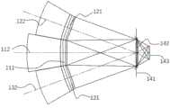
如图1所示,该激光雷达接收组件包括:接收透镜组、视场光阑141、场镜142以及光电探测器143;As shown in FIG. 1 , the lidar receiving assembly includes: a receiving lens group, a
其中,接收透镜组包括多个透镜,为了便于说明,如图1所示,本实施例中将以透镜的数量为3个进行说明,即接收透镜组包括第一透镜111,第二透镜121,第三透镜131。Among them, the receiving lens group includes a plurality of lenses. For the convenience of description, as shown in FIG. 1 , in this embodiment, the number of lenses is 3, that is, the receiving lens group includes a
所述第一透镜111的光轴为112,所述第二透镜121的光轴为122,所述第三透镜131的光轴为132,而不同透镜的主光轴之间成预设角度,不同透镜用于接收不同视场方向上的激光回波光束,以使接收到的各所述激光回波光束依次通过所述视场光阑141和所述场镜142并成像在所述光电探测器143上。The optical axis of the
具体的,所述的第一透镜111,第二透镜121,第三透镜131的焦长分别为f1、f2、f3。所述的视场光阑141的尺寸为D。所述第一透镜111用于接收来自中间视场方向的激光回波光束,且所述第一透镜111的视场大小ω1;所述的第二透镜121可用于接收来自上方视场方向的激光回波光束,且所述第二透镜121视场大小ω2;所述的第三透镜131用于接收来自下方视场方向的激光回波光束,且第三透镜131的视场大小ω3。Specifically, the focal lengths of the
而所述的第一透镜光轴112与所述的第二透镜光轴122之间的夹角表示为α1,所述的第一透镜光轴112与所述的第三透镜光轴132之间的夹角表示为α2。优选的,相邻的两个透镜的主光轴之间的预设夹角小于等于该两个透镜的视场角之和的二分之一。The angle between the
具体的,各夹角与各透镜视场大小之间的关系需满足如下公式a和公式b:Specifically, the relationship between each included angle and the size of the field of view of each lens needs to satisfy the following formula a and formula b:
a1≤(ω1+ω2)/2 公式aa1 ≤(ω1 +ω2 )/2 Formula a
a3≤(ω1+ω3)/2 公式b。a3 ≤(ω1 +ω3 )/2 Formula b.
而在各透镜接收有其相应视场方向上的激光回波光束之后,各透镜将分别引导激光回波光束穿过视场光阑141的孔径,并经过场镜142的汇聚作用,最终成像在光电探测器143上。After each lens receives the laser echo beam in its corresponding field of view direction, each lens will respectively guide the laser echo beam to pass through the aperture of the
此时,整个激光雷达接收组件的整体视场ω将满足公式c:At this time, the overall field of view ω of the entire lidar receiving component will satisfy the formula c:
ω≤α1+α2+(ω4+ω3)/2 公式cω≤α1 +α2 +(ω4 +ω3 )/2 Formula c
在上述实施方式的基础上,优选的,接收透镜组中的各透镜的焦点重合设置。通过采用该焦点重合的透镜设置方式,能够便于进一步缩小视场光阑的孔径尺寸,降低整个组件的尺寸。On the basis of the above-mentioned embodiment, preferably, the focal points of each lens in the receiving lens group are set to coincide with each other. By adopting the lens arrangement with the coincident focus, the aperture size of the field diaphragm can be further reduced, and the size of the entire assembly can be reduced.
而更优的所述各透镜的焦点位于所述视场光阑的孔径所在平面上。也就是说,所述的第一透镜111、所述的第二透镜121以及所述的第三透镜131的像方焦点重合,并且所述的像方焦点位于所述的视场光阑141的中心。如前所述的,当各透镜的焦点均位于所述视场光阑141的孔径所在平面上,此时的视场光阑141的孔径尺寸将达到最小值。More preferably, the focal point of each lens is located on the plane where the aperture of the field diaphragm is located. That is to say, the image-side focal points of the
此外,在上述实施方式的基础上,接收透镜组中的各透镜为汇聚透镜,用于将各激光回波光束汇聚在所述视场光阑141内。由于采用分别汇聚的方式,视场光阑141是传统的接收系统光电探测器的1/3,有效的减少了探测器的尺寸。In addition, on the basis of the above-mentioned embodiment, each lens in the receiving lens group is a condensing lens, which is used for converging each laser echo beam in the
此外,可选的,所述场镜142用于将透过所述视场光阑141的各激光回波光束进行压缩汇聚,以使压缩汇聚后的回波光束成像在所述光电探测器143的探测区域内。通过设置用于近一步缩小成像尺寸的场镜142,第一透镜111、第二透镜121和第三透镜131对应的视场内的回波光束均汇聚到视场光阑141内,并由场镜142将汇聚后的光线进行进一步压缩,汇聚到所述的光电探测器143上,实现最终成像。In addition, optionally, the
图2为本发明实施例一提供的激光雷达接收组件中的主透镜的路示意图,所述第一透镜111所能接收的视场为-ω11~ω12,ω11+ω12=ω1。对于第一透镜111,其接收视场外的光线将被所述的视场光阑141遮挡,不能够进入所述的场镜142以及后方的所述的探测器143上。其中的下视场的激光回波光束113与所述的第一透镜光轴112之间的夹角为-ω11,经过所述的第一透镜111后汇聚到所述的视场光阑141的上部。所述的场镜142位于所述的视场光阑141的后方附近。汇聚后的光线经过所述的场镜142后,光线高度被压缩,最终成像在所述的探测器143上。所述的上视场激光回波光束114与所述的第一透镜光轴112之间的夹角为ω12,经过所述的第一透镜111后汇聚到所述的视场光阑141的下部。汇聚后的光线经过所述的场镜142后,光线高度被压缩,最终成像在所述的探测器143上。使用所述的场镜141,入射光线的高度被压缩,像面尺寸被进一步的缩小,可以有效的缩小所述的探测器143的尺寸,降低成本。FIG. 2 is a schematic diagram of the main lens in the lidar receiving assembly according to
优选的,在本实施方式中,视场光阑141的孔径大小等于任一透镜的上视场角的正切值与下视场角的正切值之和,乘以该任一透镜的焦距;其中,所述上视场角为该透镜所接收的上视场激光回波光束的传播方向与该透镜主光轴之间的夹角;所述下视场角为该透镜所接收的下视场激光回波光束的传播方向与该透镜主光轴之间的夹角。Preferably, in this embodiment, the aperture size of the
而相应的,所述相邻的两个透镜的上、下视场角之间满足如下公式1:Correspondingly, the following

其中,所述f1为相邻的两个透镜中其中一个透镜的焦距,

具体的,图3为本发明实施例一提供的激光雷达接收组件中主透镜的工作原理示意图。Specifically, FIG. 3 is a schematic diagram of the working principle of the main lens in the lidar receiving assembly provided by
所述的第一接收透镜111负责正前方视场,因此,将所述的第一透镜111的高斯像面与所述的视场光阑141重合。所述的第一透镜的下视场激光回波光束113经过所述的第一透镜111后汇聚点的高度D11=f1×tanω11。第一透镜的上视场激光回波光束114经过所述的第一透镜111后汇聚点的高度D12=f1×tanω12。所述的视场光阑141的整体高度D=D11+D12。The
所述的第二透镜的下视场激光回波光束123与所述的第二透镜光轴112之间的夹角为ω21,经过所述的第二透镜121后汇聚到所述的第二透镜122的高斯像面145的高度D21=f2×tanω21。为了保证所述的第二透镜的下视场激光回波光束123的所有光线都能够透过所述的视场光阑141,因此必须保证汇聚光束的最上端通过所述的视场光阑141。所述的第二接收透镜121的口径为

因此,所述的第二透镜122的下视场角应满足公式d:Therefore, the lower viewing angle of the

所述的第二上视场激光回波信号124与所述的第二透镜光轴112之间的夹角为ω22,经过所述的第二透镜121后汇聚到所述的第二透镜121的高斯像面145的高度D22=f2×tanω22。其中ω2=ω21+ω22。为了保证所述的第二透镜的上视场激光回波光束123的所有光线都能够透过所述的视场光阑141,因此必须保证汇聚光束的最下端通过所述的视场光阑141。通过计算可知,所述的第二透镜的上视场激光回波光束123经过所述的第二透镜The angle between the second upper field of view laser echo signal 124 and the
121后汇聚到所述的第二透镜122的高斯像面145的高度应满足公式eThe height of the

因此,所述的第二透镜的上视场角应满足公式f:Therefore, the upper field of view of the second lens should satisfy the formula f:

本发明的激光雷达接收组件,通过在接收透镜组中设置多个可用于接收不同视场方向上激光回波光束,并利用视场光阑和场镜将激光回波光束进行汇聚成像在光电探测器上,以使激光雷达接收组件的整体视场在不改变光电探测器尺寸的情况下得到有效扩展,也有效的减小探测器的尺寸,突破现有半导体制备工艺水平的限制,降低激光雷达成本。此外,在本实施方式中,由于多个透镜共用一个视场光阑、场镜以及光电探测器,也避免采用多个视场光阑、场镜以及光电探测器进行视场拼接时所造成的成本升高的问题。In the laser radar receiving assembly of the present invention, a plurality of laser echo beams in different field of view directions are arranged in the receiving lens group, and the laser echo beams are converged and imaged by the field diaphragm and the field lens in the photoelectric detector. On the device, so that the overall field of view of the lidar receiving component can be effectively expanded without changing the size of the photodetector, and the size of the detector can also be effectively reduced, breaking through the limitations of the existing semiconductor manufacturing technology level, reducing the laser radar. cost. In addition, in this embodiment, since multiple lenses share one field diaphragm, field lens, and photodetector, it also avoids the occurrence of field splicing by using multiple field diaphragms, field lenses, and photodetectors. the issue of rising costs.
为了进一步提高激光雷达接收组件的器件性能,接收透镜组中的多个透镜可采用不同的排布方式,以接收不同视场方向的激光回波光束。In order to further improve the device performance of the lidar receiving component, the multiple lenses in the receiving lens group can be arranged in different ways to receive laser echo beams in different field of view directions.
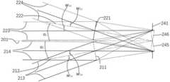
具体来说,图4为本发明实施例二提供的一种激光雷达接收组件的结构示意图。Specifically, FIG. 4 is a schematic structural diagram of a lidar receiving assembly according to
在本发明中,接收透镜组中各透镜的排布可如图1所示,多个透镜沿同一弯曲方向依次排布,其还可采用如图4所示的排布方式,即多个透镜沿不同的弯曲方向依次排布。In the present invention, the arrangement of each lens in the receiving lens group can be as shown in FIG. 1 , and multiple lenses are arranged in sequence along the same bending direction, and the arrangement as shown in FIG. 4 can also be used, that is, multiple lenses Arranged in sequence along different bending directions.
在图4所示结构中,激光雷达接收组件包括第一透镜211,第二透镜221,第三透镜231,第四透镜241,视场光阑251,场镜252以及光电探测器253。In the structure shown in FIG. 4 , the lidar receiving assembly includes a
其中所述第一透镜211的光轴为212,所述第二透镜221的光轴为222,所述第三透镜231的光轴为232,所述第四透镜211的光轴为212。其中,水平基准面为201,与所述的视场光阑251的Dx方向一致,竖直基准面为202,与所述的视场光阑251的Dy方向一致。The optical axis of the
所述的第一透镜211,第二透镜221,第三透镜231,第四透镜241的焦长分别为f1、f2、f3、f4。所述的视场光阑251的尺寸为Dx×Dy。所述的第一透镜211的视场大小:ω1x,ω1y;第二透镜221的视场大小ω2x,ω2y;所述的第三透镜231视场大小ω3x,ω3y;所述的第四透镜241的视场大小ω4x,ω4y。The focal lengths of the
其中,所述的第一透镜111、所述的第二透镜121、所述的第三透镜131以及所述的第四透镜141的像方焦点重合,并且所述的像方焦点位于所述的视场光阑251的中心。所述的第一透镜光轴212与所述的竖直基准202之间的夹角为α1,所述的第一透镜光轴212与所述的水平基准201之间的夹角为β1,且
所述的第二透镜光轴222与所述的竖直基准202之间的夹角为α2,所述的第二透镜光轴222与所述的水平基准201之间的夹角为β2,且
所述的第三透镜光轴232与所述的竖直基准202之间的夹角为α3,所述的第三透镜光轴232与所述的水平基准201之间的夹角为β3,且
所述的第四透镜光轴242与所述的竖直基准202之间的夹角为α4,所述的第四透镜光轴242与所述的水平基准201之间的夹角为β4,且
进一步来说,图5为本发明实施例二提供的一种激光雷达接收组件的主透镜的工作原理示意图。图5为相邻两个接收透镜在所述的水平基准面201上的投影。所述的第一透镜的下视场激光回波光束113与所述的第一透镜光轴112之间的夹角为ω1x1,经过所述的第一透镜211后汇聚到所述的第一透镜211的高斯像面245的高度D11=f1×tanω1x1。为了保证所述的第一透镜的下视场激光回波光束213的所有光线都能够透过所述的视场光阑241,因此必须保证汇聚光束的最上端通过所述的视场光阑241。所述的第一接收透镜211的口径为

因此,所述的第一透镜的下视场角为
所述的第一透镜的上视场激光回波光束214与所述的第一透镜光轴211之间的夹角为ω1x2,经过所述的第一透镜121后汇聚到所述的第一透镜211的高斯像面145的高度D12=f2×tanω1x2。为了保证所述的第一透镜的上视场激光回波光束214的所有光线都能够透过所述的视场光阑241,因此必须保证汇聚光束的最下端通过所述的视场光阑241。通过计算可知,所述的第一透镜的下视场激光回波光束213经过所述的第一透镜211后汇聚到所述的第一透镜211的高斯像面145的高度为The angle between the upper field of view

因此,所述的第二透镜的上视场角为Therefore, the upper field of view of the second lens is

同理,第二透镜对应的上下视场角ω21、ω22,满足公式g:Similarly, the upper and lower field angles ω21 and ω22 corresponding to the second lens satisfy the formula g:

其中ω2x=ω2x1+ω2x2。where ω2x =ω2x1 +ω2x2 .
同理,还可获得在所述的竖直平面202上,相邻两路视场ω1y1、ω1y2、ω2y2、ω2y2需要满足公式h:Similarly, it can also be obtained that on the

本发明实施例二提供的激光雷达组件,通过多个透镜可采用不同的排布方式,以接收不同视场方向的激光回波光束,以进一步提高激光雷达接收组件的性能。The laser radar assembly provided by the second embodiment of the present invention can adopt different arrangements through multiple lenses to receive laser echo beams in different field of view directions, so as to further improve the performance of the laser radar receiving assembly.
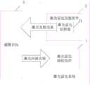
在上述实施例的基础上,图6为本发明实施例三提供的一种激光雷达系统的结构示意图。On the basis of the foregoing embodiment, FIG. 6 is a schematic structural diagram of a lidar system according to
如图6所示,该激光雷达系统包括上述任一项所述的激光雷达接收组件1以及激光雷达发射组件2。As shown in FIG. 6 , the lidar system includes the
其中,所述激光雷达发射组件2包括激光发射器21;所述激光发射器21用于发射激光发射光束至被测目标3,并经由所述被测目标反射形成射入所述激光雷达接收组件1的激光回波光束。Wherein, the
本发明实施例三提供的激光雷达系统,通过在激光雷达接收组件中设置接收透镜组、视场光阑、场镜以及光电探测器;其中,所述接收透镜组包括多个透镜;不同透镜的主光轴之间成预设角度;不同透镜用于接收不同视场方向上的激光回波光束,以使接收到的各所述激光回波光束依次通过所述视场光阑和所述场镜并成像在所述光电探测器上。通过采用设置多个透镜的方式,以使不同透镜可接收来自不同视场方向上的激光回波光束,并经视场光阑和场镜成像在光电探测器,从而有效提高了光电探测器的可探测视场,进而提高激光雷达接收组件和激光雷达系统的探测性能。In the laser radar system provided by the third embodiment of the present invention, a receiving lens group, a field diaphragm, a field lens and a photodetector are arranged in the laser radar receiving assembly; wherein, the receiving lens group includes a plurality of lenses; A preset angle is formed between the main optical axes; different lenses are used to receive laser echo beams in different field of view directions, so that each received laser echo beam passes through the field diaphragm and the field in turn mirror and image on the photodetector. By arranging multiple lenses, different lenses can receive laser echo beams from different field of view directions, and image them on the photodetector through the field diaphragm and field lens, thereby effectively improving the photodetector’s performance. The field of view can be detected, thereby improving the detection performance of the lidar receiver assembly and lidar system.
以上所述的具体实施例,对本发明的目的、技术方案和有益效果进行了进一步详细说明,所应理解的是,以上所述仅为本发明的具体实施例而已,并不用于限定本发明的保护范围,凡在本发明的精神和原则之内,所做的任何修改、等同替换、改进等,均应包含在本发明的保护范围之内。The specific embodiments described above further describe the purpose, technical solutions and beneficial effects of the present invention in detail. It should be understood that the above-mentioned specific embodiments are only specific embodiments of the present invention, and are not intended to limit the scope of the present invention. Any modification, equivalent replacement, improvement, etc. made within the spirit and principle of the present invention shall be included within the protection scope of the present invention.
最后应说明的是:以上各实施例仅用以说明本发明的技术方案,而非对其限制;尽管参照前述各实施例对本发明进行了详细的说明,本领域的普通技术人员应当理解:其依然可以对前述各实施例所记载的技术方案进行修改,或者对其中部分或者全部技术特征进行等同替换;而这些修改或者替换,并不使相应技术方案的本质脱离本发明各实施例技术方案的范围。Finally, it should be noted that the above embodiments are only used to illustrate the technical solutions of the present invention, but not to limit them; although the present invention has been described in detail with reference to the foregoing embodiments, those of ordinary skill in the art should understand that: The technical solutions described in the foregoing embodiments can still be modified, or some or all of the technical features thereof can be equivalently replaced; and these modifications or replacements do not make the essence of the corresponding technical solutions deviate from the technical solutions of the embodiments of the present invention. scope.
Claims (10)
Translated fromChinese


Priority Applications (1)
| Application Number | Priority Date | Filing Date | Title |
|---|---|---|---|
| CN201811613937.0ACN111381246B (en) | 2018-12-27 | 2018-12-27 | Laser radar receiving component and laser radar system |
Applications Claiming Priority (1)
| Application Number | Priority Date | Filing Date | Title |
|---|---|---|---|
| CN201811613937.0ACN111381246B (en) | 2018-12-27 | 2018-12-27 | Laser radar receiving component and laser radar system |
Publications (2)
| Publication Number | Publication Date |
|---|---|
| CN111381246Atrue CN111381246A (en) | 2020-07-07 |
| CN111381246B CN111381246B (en) | 2025-07-11 |
Family
ID=71214693
Family Applications (1)
| Application Number | Title | Priority Date | Filing Date |
|---|---|---|---|
| CN201811613937.0AActiveCN111381246B (en) | 2018-12-27 | 2018-12-27 | Laser radar receiving component and laser radar system |
Country Status (1)
| Country | Link |
|---|---|
| CN (1) | CN111381246B (en) |
Cited By (7)
| Publication number | Priority date | Publication date | Assignee | Title |
|---|---|---|---|---|
| CN112612014A (en)* | 2020-11-27 | 2021-04-06 | 西安知微传感技术有限公司 | High-performance MEMS laser radar receiving system |
| CN114325640A (en)* | 2021-11-18 | 2022-04-12 | 杭州宏景智驾科技有限公司 | A lidar receiving device and lidar |
| CN114460556A (en)* | 2020-11-09 | 2022-05-10 | 北京万集科技股份有限公司 | Laser radar assembly and laser radar system |
| CN114594449A (en)* | 2020-12-04 | 2022-06-07 | 上海禾赛科技有限公司 | Detection device, detection method and lidar |
| CN117368886A (en)* | 2022-06-30 | 2024-01-09 | 深圳市速腾聚创科技有限公司 | Laser emission module and laser radar |
| CN117518125A (en)* | 2022-07-29 | 2024-02-06 | 深圳市速腾聚创科技有限公司 | Lidar and lidar design methods |
| WO2025113397A1 (en)* | 2023-11-27 | 2025-06-05 | 北京石头世纪科技股份有限公司 | Optical module and cleaning device |
Citations (13)
| Publication number | Priority date | Publication date | Assignee | Title |
|---|---|---|---|---|
| JPH04218790A (en)* | 1990-12-19 | 1992-08-10 | Mitsubishi Electric Corp | Measuring apparatus of distance |
| DE10226444A1 (en)* | 2002-06-13 | 2004-01-15 | Samland, Thomas, Dipl.-Math. | Apparatus for micro optical position measuring such as for incremental or absolute measurement of angles or lengths where a bending angle is calculated from the order of a diffractive optical element |
| CN1967284A (en)* | 2006-09-14 | 2007-05-23 | 中国科学院安徽光学精密机械研究所 | Laser radar transmission type dual-focus light receiving and emitting optical system |
| CN102571204A (en)* | 2011-12-09 | 2012-07-11 | 西安电子科技大学 | Optical transmitting antenna system and beam control method thereof |
| CN103018735A (en)* | 2012-12-13 | 2013-04-03 | 中国科学院上海光学精密机械研究所 | Synthetic aperture laser imaging radar large-visual-field heterodyne detection device |
| CN105403877A (en)* | 2015-11-12 | 2016-03-16 | 中国科学院上海光学精密机械研究所 | Large dynamic range optical sub-field detection laser radar |
| CN106338725A (en)* | 2016-08-31 | 2017-01-18 | 深圳市微觉未来科技有限公司 | Optical module for low cost laser distance measurement |
| CN206114895U (en)* | 2016-09-13 | 2017-04-19 | 深圳市佶达德科技有限公司 | Laser radar optical receiving device |
| CN207457496U (en)* | 2017-11-23 | 2018-06-05 | 北京万集科技股份有限公司 | Laser radar Optical devices and laser radar system based on more visual field light combination mirrors |
| CN108445619A (en)* | 2018-05-11 | 2018-08-24 | 中国工程物理研究院流体物理研究所 | Optical scanning system and method |
| CN108710135A (en)* | 2018-06-14 | 2018-10-26 | 浙江华是科技股份有限公司 | A kind of video mosaic system configuring big visual field laser three-D detection for different axis |
| CN109416399A (en)* | 2016-04-26 | 2019-03-01 | 深瞳科技公司 | 3D imaging system |
| CN209842063U (en)* | 2018-12-27 | 2019-12-24 | 北京万集科技股份有限公司 | Laser radar receiving assembly and laser radar system |
- 2018
- 2018-12-27CNCN201811613937.0Apatent/CN111381246B/enactiveActive
Patent Citations (13)
| Publication number | Priority date | Publication date | Assignee | Title |
|---|---|---|---|---|
| JPH04218790A (en)* | 1990-12-19 | 1992-08-10 | Mitsubishi Electric Corp | Measuring apparatus of distance |
| DE10226444A1 (en)* | 2002-06-13 | 2004-01-15 | Samland, Thomas, Dipl.-Math. | Apparatus for micro optical position measuring such as for incremental or absolute measurement of angles or lengths where a bending angle is calculated from the order of a diffractive optical element |
| CN1967284A (en)* | 2006-09-14 | 2007-05-23 | 中国科学院安徽光学精密机械研究所 | Laser radar transmission type dual-focus light receiving and emitting optical system |
| CN102571204A (en)* | 2011-12-09 | 2012-07-11 | 西安电子科技大学 | Optical transmitting antenna system and beam control method thereof |
| CN103018735A (en)* | 2012-12-13 | 2013-04-03 | 中国科学院上海光学精密机械研究所 | Synthetic aperture laser imaging radar large-visual-field heterodyne detection device |
| CN105403877A (en)* | 2015-11-12 | 2016-03-16 | 中国科学院上海光学精密机械研究所 | Large dynamic range optical sub-field detection laser radar |
| CN109416399A (en)* | 2016-04-26 | 2019-03-01 | 深瞳科技公司 | 3D imaging system |
| CN106338725A (en)* | 2016-08-31 | 2017-01-18 | 深圳市微觉未来科技有限公司 | Optical module for low cost laser distance measurement |
| CN206114895U (en)* | 2016-09-13 | 2017-04-19 | 深圳市佶达德科技有限公司 | Laser radar optical receiving device |
| CN207457496U (en)* | 2017-11-23 | 2018-06-05 | 北京万集科技股份有限公司 | Laser radar Optical devices and laser radar system based on more visual field light combination mirrors |
| CN108445619A (en)* | 2018-05-11 | 2018-08-24 | 中国工程物理研究院流体物理研究所 | Optical scanning system and method |
| CN108710135A (en)* | 2018-06-14 | 2018-10-26 | 浙江华是科技股份有限公司 | A kind of video mosaic system configuring big visual field laser three-D detection for different axis |
| CN209842063U (en)* | 2018-12-27 | 2019-12-24 | 北京万集科技股份有限公司 | Laser radar receiving assembly and laser radar system |
Cited By (7)
| Publication number | Priority date | Publication date | Assignee | Title |
|---|---|---|---|---|
| CN114460556A (en)* | 2020-11-09 | 2022-05-10 | 北京万集科技股份有限公司 | Laser radar assembly and laser radar system |
| CN112612014A (en)* | 2020-11-27 | 2021-04-06 | 西安知微传感技术有限公司 | High-performance MEMS laser radar receiving system |
| CN114594449A (en)* | 2020-12-04 | 2022-06-07 | 上海禾赛科技有限公司 | Detection device, detection method and lidar |
| CN114325640A (en)* | 2021-11-18 | 2022-04-12 | 杭州宏景智驾科技有限公司 | A lidar receiving device and lidar |
| CN117368886A (en)* | 2022-06-30 | 2024-01-09 | 深圳市速腾聚创科技有限公司 | Laser emission module and laser radar |
| CN117518125A (en)* | 2022-07-29 | 2024-02-06 | 深圳市速腾聚创科技有限公司 | Lidar and lidar design methods |
| WO2025113397A1 (en)* | 2023-11-27 | 2025-06-05 | 北京石头世纪科技股份有限公司 | Optical module and cleaning device |
Also Published As
| Publication number | Publication date |
|---|---|
| CN111381246B (en) | 2025-07-11 |
Similar Documents
| Publication | Publication Date | Title |
|---|---|---|
| CN111381246A (en) | Lidar receiving components and Lidar systems | |
| US10151905B2 (en) | Image capture system and imaging optical system | |
| CN109661594B (en) | Medium Range Optical Systems for Remote Sensing Receivers | |
| CN103323113B (en) | Multispectral imager based on light fieldd imaging technique | |
| JP2016005198A (en) | Imaging apparatus | |
| CN105635530B (en) | Optical field imaging system | |
| CN108027425A (en) | Laser radar sensor | |
| CN120233370A (en) | Light emitting device, light detecting device, and laser radar | |
| CN108169847A (en) | A kind of large field of view scan imaging optical system | |
| US9746323B2 (en) | Enhanced optical detection and ranging | |
| CN102289056B (en) | Front objective lens with large field of view and large relative aperture for imaging spectrograph | |
| CN209842063U (en) | Laser radar receiving assembly and laser radar system | |
| US10178372B2 (en) | Long focal length monocular 3D imager | |
| EP3343208B1 (en) | Device provided with optical unit | |
| US20240085532A1 (en) | Optical detection system with anamorphic prism | |
| CN207937636U (en) | A large field of view scanning imaging optical system | |
| CN207336913U (en) | Omnidirectional imaging system and electronic equipment | |
| US20210278640A1 (en) | Set of negative meniscus lenses, wide-angle optical system, image pickup apparatus, and projection apparatus | |
| WO2024051214A1 (en) | Three-dimensional image collection apparatus and method, and related device | |
| CN214315372U (en) | Cameras and their imaging components | |
| CN207336912U (en) | Omnidirectional imaging system and electronic equipment | |
| JP2017110965A (en) | Light wave distance-measuring device | |
| CN113419247A (en) | Laser detection system | |
| CN221977108U (en) | LiDAR | |
| CN115963478B (en) | Optical system, transmitting device, receiving device and laser radar |
Legal Events
| Date | Code | Title | Description |
|---|---|---|---|
| PB01 | Publication | ||
| PB01 | Publication | ||
| SE01 | Entry into force of request for substantive examination | ||
| SE01 | Entry into force of request for substantive examination | ||
| TA01 | Transfer of patent application right | ||
| TA01 | Transfer of patent application right | Effective date of registration:20231214 Address after:430200, 7th floor, Building 3, Phase II, Modern Service Industry Demonstration Base, Huazhong University of Science and Technology Science Park, Guandong Street, Donghu New Technology Development Zone, Wuhan City, Hubei Province Applicant after:Wuhan Wanji Photoelectric Technology Co.,Ltd. Address before:Wanji space, building 12, Zhongguancun Software Park, yard 8, Dongbei Wangxi Road, Haidian District, Beijing 100193 Applicant before:BEIJING WANJI TECHNOLOGY Co.,Ltd. | |
| GR01 | Patent grant | ||
| GR01 | Patent grant |