CN111379551A - Natural potential logging method - Google Patents
Natural potential logging methodDownload PDFInfo
- Publication number
- CN111379551A CN111379551ACN202010093117.4ACN202010093117ACN111379551ACN 111379551 ACN111379551 ACN 111379551ACN 202010093117 ACN202010093117 ACN 202010093117ACN 111379551 ACN111379551 ACN 111379551A
- Authority
- CN
- China
- Prior art keywords
- reference electrode
- measuring
- potential
- electrode
- measurement
- Prior art date
- Legal status (The legal status is an assumption and is not a legal conclusion. Google has not performed a legal analysis and makes no representation as to the accuracy of the status listed.)
- Granted
Links
Images


Classifications
- E—FIXED CONSTRUCTIONS
- E21—EARTH OR ROCK DRILLING; MINING
- E21B—EARTH OR ROCK DRILLING; OBTAINING OIL, GAS, WATER, SOLUBLE OR MELTABLE MATERIALS OR A SLURRY OF MINERALS FROM WELLS
- E21B47/00—Survey of boreholes or wells
- E—FIXED CONSTRUCTIONS
- E21—EARTH OR ROCK DRILLING; MINING
- E21B—EARTH OR ROCK DRILLING; OBTAINING OIL, GAS, WATER, SOLUBLE OR MELTABLE MATERIALS OR A SLURRY OF MINERALS FROM WELLS
- E21B49/00—Testing the nature of borehole walls; Formation testing; Methods or apparatus for obtaining samples of soil or well fluids, specially adapted to earth drilling or wells
Landscapes
- Life Sciences & Earth Sciences (AREA)
- Engineering & Computer Science (AREA)
- Geology (AREA)
- Mining & Mineral Resources (AREA)
- Physics & Mathematics (AREA)
- Environmental & Geological Engineering (AREA)
- Fluid Mechanics (AREA)
- General Life Sciences & Earth Sciences (AREA)
- Geochemistry & Mineralogy (AREA)
- Geophysics (AREA)
- Geophysics And Detection Of Objects (AREA)
Abstract
Description
Translated fromChinese技术领域technical field
本发明涉及测井领域,尤其涉及一种自然电位测井方法。The invention relates to the field of well logging, in particular to a natural potential logging method.
背景技术Background technique
测井是一种勘探与开发油气田的重要方法技术,其工作原理是:把各种专门仪器,下入井中并沿井筒移动,以测量并记录随深度变化的各种地球物理参数,利用这些参数和地质信息之间的对应关系,来识别地下的油、气、水层。Well logging is an important method and technology for exploration and development of oil and gas fields. Its working principle is: put various special instruments into the well and move along the wellbore to measure and record various geophysical parameters that vary with depth, and use these parameters. and the corresponding relationship between geological information to identify underground oil, gas and water layers.
自然电位测井是一种电法测井,由于自然电位测井曲线在渗透层处有明显的异常显示,因此,它是划分和评价储集层的重要方法之一。其基本原理为:由于井中流体与地层流体之间会发生电化学作用,井中存在着自然电场,具体现象是,在未通电的情况下,井中电极与地面电极之间存在电位差,且该电位差随着地层的不同而变化,并具有一定的规律性。自然电位测井测量的是这种自然电位差随井深变化的曲线。Spontaneous potential logging is a kind of electrical logging. Since the spontaneous potential logging curve shows obvious abnormality at the permeable layer, it is one of the important methods to divide and evaluate the reservoir. The basic principle is: due to the electrochemical interaction between the fluid in the well and the formation fluid, there is a natural electric field in the well. The difference varies with the stratum and has a certain regularity. Spontaneous potential logging measures the curve of this spontaneous potential difference as a function of well depth.
目前自然电位测量方法有两种,分别是:有地面参考电极的测量方法和无地面参考电极的测量方法,其中前者为主流的自然电位测量方法,后者只在5700测井仪中有少量应用。At present, there are two kinds of spontaneous potential measurement methods, namely: the measurement method with ground reference electrode and the measurement method without ground reference electrode. .
如图1所示,有地面参考电极的测量方法是将一个电极R放在地面上接地,另一个电极M放入井中,在不存在任何人工电场的情况下,由于存在自然电场,电极R具有电位ER,电极M具有电位EM,用测量电位差的仪器可测量M电极相对于R电极之间的电位差ΔE=EM-ER。当电极M在井内连续移动时,电极M具有的电位就是一个随深度变化的函数EM(h),用测量电位差的仪器测得的就是井内自然电位差沿井剖面的变化曲线SP=EM(h)-ER,即自然电位曲线。由于固定在地面上的R电极的电位ER是一个恒定值,但上述方法由于有地面参考电极的自然电位测井测得的是井中电极相对于地面参考电极的电位差,其中需要用电缆将井中电极和提供恒定参考电位的地面参考电极相连,所以此方法只适用于传统的电缆测井,不适用于无电缆过钻具存储式测井以及随钻测井等无电缆测井施工工艺。As shown in Figure 1, the measurement method with ground reference electrodes is to place one electrode R on the ground to ground, and the other electrode M into the well. In the absence of any artificial electric field, due to the existence of a natural electric field, the electrode R has The potential ER , the electrode M has the potential EM , and the potential difference ΔE=EM - ER between theM electrode and the R electrode can be measured with an instrument for measuring the potential difference. When the electrode M moves continuously in the well, the potential of the electrode M is a function EM (h) that changes with the depth. What is measured by the instrument for measuring the potential difference is the variation curve of the natural potential difference in the well along the well profile SP=EM (h)-ER , the spontaneous potential curve. Since the potential ER of the R electrode fixed on the ground is a constant value, the above method measures the potential difference between the electrode in the well relative to the ground reference electrode due to the natural potential logging with the ground reference electrode, which requires a cable to connect The electrode in the well is connected to the ground reference electrode that provides a constant reference potential, so this method is only suitable for traditional wireline logging, and is not suitable for wireline-free logging construction techniques such as wireless through-drilling logging and logging while drilling.
如图2所示,目前的无地面参考电极的测量方法,是在下井仪器上设置一个测量电极,以下井仪器的外壳或井下管柱作参考电极,由于参考电极范围较大,不是一个点,且仪器或管柱在不断移动,所以所获取的参考电位是不断变化的,不是一个恒定值,因此,测得的自然电位是不准确的。目前还没有可用的无地面参考电极的自然电位测井方法。As shown in Figure 2, the current measurement method without ground reference electrode is to set a measurement electrode on the downhole tool, and use the casing of the downhole tool or the downhole pipe string as the reference electrode. Because the reference electrode has a large range, it is not a point. And the instrument or the string is constantly moving, so the obtained reference potential is constantly changing, not a constant value, therefore, the measured natural potential is inaccurate. There is currently no available spontaneous potential logging method without a ground reference electrode.
发明内容SUMMARY OF THE INVENTION
为了解决上述问题,本发明提供一种无地面参考电极但有恒定参考电位的自然电位测量方法。In order to solve the above problems, the present invention provides a method for measuring the natural potential without a ground reference electrode but with a constant reference potential.
为达到上述目的,本发明的技术方案为:For achieving the above object, the technical scheme of the present invention is:
一种自然电位测井方法,其特征在于,测量仪器上设有至少一个参考电极,以及与所述参考电极按照预设间隔设置的多个测量电极,该方法包括如下步骤:将所述参考电极移动至第一预设深度,测量每个所述测量电极与所述参考电极之间的电位差,移动测量仪器以使所述参考电极移动至上一测量点时其中一个所述测量电极的测量位置,测量此时每个所述测量电极与所述参考电极之间的电位差,以上述方式移动测量仪器至所述参考电极移动至第二预设深度,根据所述参考电极位于所述第一预设深度或第二预设深度的电位,以及各个测量位置处所述测量电极与所述参考电极的电位差计算每个测量点处的电位。A self-potential logging method, characterized in that a measuring instrument is provided with at least one reference electrode, and a plurality of measuring electrodes arranged at preset intervals from the reference electrode, the method comprising the steps of: connecting the reference electrode to Move to a first preset depth, measure the potential difference between each of the measurement electrodes and the reference electrode, and move the measuring instrument to make the reference electrode move to the measurement position of one of the measurement electrodes at the last measurement point , measure the potential difference between each of the measuring electrodes and the reference electrode at this time, move the measuring instrument in the above-mentioned manner until the reference electrode moves to a second preset depth, according to the position of the reference electrode in the first The potential at the preset depth or the second preset depth, and the potential difference between the measurement electrode and the reference electrode at each measurement position are used to calculate the potential at each measurement point.
作为优选,多个所述测量电极和所述参考电极均匀距离间隔设置,该方法还包括如下步骤:将所述测量仪器按照所述测量电极的间距依次移动。Preferably, a plurality of the measuring electrodes and the reference electrodes are arranged at a uniform distance, and the method further includes the step of: moving the measuring instrument in sequence according to the distance between the measuring electrodes.
作为优选,还包括如下步骤:该测量位置处所述参考电极的电位为:Preferably, it also includes the following steps: the potential of the reference electrode at the measurement position is:

其中,


作为优选,还包括如下步骤:将第i-1处测量点测量所得的所述参考电极的电位以及多个所述测量电极的电位差的数据的SP曲线进行插值计算,从而求得

作为优选,还包括如下步骤:根据上一测量点处所述参考电极的电位,以及上一测量位置和该测量点的多个所述测量电极与所述参考电极的电位差数据,计算出多组该测量点处所述参考电极的电位数据,排除异常数据后将其余数据进行平均计算,作为该测量位置处所述参考电极的电位。Preferably, the method further includes the following step: according to the potential of the reference electrode at the last measurement point, and the data of the potential difference between the measurement electrodes and the reference electrode at the last measurement position and the measurement point, calculate the number of The potential data of the reference electrode at the measurement point is grouped, and after excluding abnormal data, the remaining data are averaged and calculated as the potential of the reference electrode at the measurement position.
与现有技术相比,本发明的有益效果在于:Compared with the prior art, the beneficial effects of the present invention are:
本发明所述的自然电位测井方法无需恒定的地面参考电极,因此无需使用电缆,适用于随钻测井、储存式测井等无电缆作业,此外,在常规的有电缆测井作业中也可使用本方法,用本方法无需地面的参考电极,且在没有恒定参考电极的情况下也可进行精准的测量,测量精确、操作简单且适用范围广。The natural potential logging method of the present invention does not require a constant ground reference electrode, so it does not need to use cables, and is suitable for cableless operations such as logging while drilling and storage logging. The method can be used, the ground reference electrode is not required, and accurate measurement can be performed without a constant reference electrode, the measurement is accurate, the operation is simple, and the application range is wide.
附图说明Description of drawings
图1为现有有地面参考电极的测量方法示意图;1 is a schematic diagram of a measurement method with a ground reference electrode in the prior art;
图2为现有无地面参考电极的测量方法示意图;2 is a schematic diagram of an existing measurement method without a ground reference electrode;
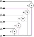
图3为本发明所述的自然电位测量方法参考电极和测量电极的排布示意图;Fig. 3 is the arrangement schematic diagram of the reference electrode and the measuring electrode of the spontaneous potential measurement method of the present invention;
图4为本发明所述的自然电位测量方法测量流程的示意图。FIG. 4 is a schematic diagram of the measurement flow of the spontaneous potential measurement method according to the present invention.
具体实施方式Detailed ways
下面,通过示例性的实施方式对本发明进行具体描述。然而应当理解,在没有进一步叙述的情况下,一个实施方式中的元件、结构和特征也可以有益地结合到其他实施方式中。Hereinafter, the present invention will be specifically described through exemplary embodiments. It should be understood, however, that elements, structures and features of one embodiment may be beneficially combined in other embodiments without further recitation.
参考图3-4,本发明提出一种自然电位测井方法,测量仪器上设有至少一个参考电极,以及与所述参考电极按照预设间隔设置的多个测量电极,该方法包括如下步骤:将所述参考电极移动至第一预设深度,测量每个所述测量电极与所述参考电极之间的电位差,移动测量仪器以使所述参考电极移动至上次测量点时其中一个所述测量电极的测量位置,测量此时每个所述测量电极与所述参考电极之间的电位差,以上述方式移动测量仪器至所述参考电极移动至第二预设深度,根据所述参考电极位于所述第一预设深度或第二预设深度的电位,以及各个测量位置处所述测量电极与所述参考电极的电位差计算每个测量点处的电位。Referring to FIGS. 3-4 , the present invention proposes a spontaneous potential logging method. The measuring instrument is provided with at least one reference electrode and a plurality of measuring electrodes arranged at preset intervals with the reference electrode. The method includes the following steps: Move the reference electrode to a first preset depth, measure the potential difference between each of the measurement electrodes and the reference electrode, and move the measuring instrument to move the reference electrode to one of the last measurement points. Measure the measurement position of the electrode, measure the potential difference between each of the measurement electrodes and the reference electrode at this time, move the measuring instrument in the above-mentioned manner until the reference electrode moves to a second preset depth, according to the reference electrode The potential at each measurement point is calculated from the potential at the first preset depth or the second preset depth, and the potential difference between the measurement electrode and the reference electrode at each measurement position.
本发明所述的自然电位测井方法无需恒定的地面参考电极,因此无需使用电缆,适用于随钻测井、储存式测井等无电缆作业,此外,在常规的有电缆作业中也可使用本方法,用本方法无需地面的参考电极,且在没有恒定参考电极的情况下也可进行精准的测量,测量精确、操作简单且适用范围广。The self-potential logging method of the present invention does not need a constant ground reference electrode, so it does not need to use cables, and is suitable for cableless operations such as logging while drilling, storage logging, etc. In addition, it can also be used in conventional cabled operations. In this method, a reference electrode on the ground is not required, and accurate measurement can be performed without a constant reference electrode, and the measurement is accurate, the operation is simple, and the application range is wide.
如图3所示,在下井的测量仪器的外壳上自下而上且等间距地依次放置一个参考电极R和N个测量电极M1、M2、......、MN,每个所述测量电极通过一个可以测量电位差的仪器与参考电极相连。理论上,所述测量电极的数量等于2即可实现本方法,但为了提高自然电位测量的准确度,需增加测量电极的数量,一般选取N≥3,图3为N=5的电极排列示意图。As shown in Fig. 3, a reference electrode R andN measurement electrodes M1 , M2 , . Each of the measuring electrodes is connected to the reference electrode by means of an instrument capable of measuring the potential difference. Theoretically, this method can be realized if the number of the measuring electrodes is equal to 2, but in order to improve the accuracy of the spontaneous potential measurement, the number of measuring electrodes needs to be increased. Generally, N≥3 is selected. Figure 3 is a schematic diagram of the electrode arrangement with N=5. .
下面以5个测量电极为例,介绍工作原理,如图4所示:The following takes 5 measuring electrodes as an example to introduce the working principle, as shown in Figure 4:
设最初6个电极R、M1、M2、M3、M4、M5分别位于图4中(a)所示的位置,电极间距为Δh,第一预设深度参考电极R所在的深度为h0,若将测量仪器向上移动1个电极间距的距离Δh,如图4中(b)所示,则所有的电极相对于图4中(a)的位置均向上移动了Δh,则参考电极R所在的深度为h1=h0+Δh。同理,继续将测量仪器向上移动1个电极间距的距离,到达图4中(c)所示位置,则参考电极和测量电极均相对于(a)的位置都向上移动了2Δh,则参考电极所在的深度为h2=h0+2Δh。以此类推,若参考电极和测量电极相对于最初的位置移动i个电极间距的距离,则第i次测量时所述参考电极所在的深度为hi=h0+iΔh。Assume that the first six electrodes R, M1 , M2 , M3 , M4 , and M5 are respectively located at the positions shown in (a) in FIG. 4 , the electrode spacing is Δh, and the first preset depth refers to the depth where the electrode R is located. is h0 , if the measuring instrument is moved upward by a distance Δh of one electrode spacing, as shown in (b) in Figure 4, then the positions of all electrodes relative to (a) in Figure 4 are moved upward by Δh, then the reference The depth at which the electrode R is located is h1 =h0 +Δh. In the same way, continue to move the measuring instrument up a distance of one electrode spacing to reach the position shown in (c) in Figure 4, then both the reference electrode and the measuring electrode move up 2Δh relative to the position of (a), then the reference electrode The depth is h2 =h0 +2Δh. By analogy, if the reference electrode and the measurement electrode are moved by a distance of i electrode pitches relative to the initial position, the depth at which the reference electrode is located in the i-th measurement is hi =h0 +iΔh.
设在初始位置h0,参考电极R的电位为


剔除上述5个值中的异常值,对其余的值求平均,即可得到位置h1处较准确的电位
同理,在位置h2,设参考电极R的电位为


剔除上述5个值中的异常值,对其余的值求平均,即可得到位置h2处较准确的电位
以此类推,可用以下5种方法得到位置hi处的电位


剔除上述5个值中的异常值,对其余的值求平均,即可得到位置hi处较准确的电位
需要说明的是,因此处所述测量电极为5个,所及计算方法为5个,如所述测量电极的数量改变,则计算方法的数量会有相应的调整。It should be noted that, therefore, the number of measurement electrodes described here is 5, and the number of calculation methods involved is 5. If the number of the measurement electrodes changes, the number of calculation methods will be adjusted accordingly.
以此操作,直至将所述参考电极移动至第二预设深度,此时所述参考电极的电位是固定且可知的,从而进行迭代计算,即当前参考电极的电位由当前各测量电极的测量值与上一次测量参考电极的电位以及各测量电极的测量值来求得。当有N个测量电极时,求第i次测量的参考电极的电位的迭代公式为:This operation is performed until the reference electrode is moved to the second preset depth. At this time, the potential of the reference electrode is fixed and known, so that the iterative calculation is performed, that is, the current potential of the reference electrode is determined by the current measurement of each measuring electrode. The value is obtained from the potential of the reference electrode in the last measurement and the measurement value of each measurement electrode. When there are N measurement electrodes, the iterative formula for finding the potential of the reference electrode measured for the i-th time is:


并根据计算所得到的多组数据,提出异常数据后求得的这N个

实际测井中,下井的测量仪器以等时的方式采集井下数据,再经过时深转换得到随深度变化的测井数据。但是由于测量仪器在井中移动的速度不均匀,导致虽然以相同的时间间隔采样,测量仪器移动的距离却不是等间隔的,即测量仪器每次移动的距离是变化的,不能保证是1个电极间距Δh,例如第次测量相对于第i-1次测量上移了0.6Δh,第i+1次测量相对于第i次测量上移了0.7Δh,针对上述问题,可以采用插值法解决此问题,具体方法如下:若第i次测量相对于第i-1次测量上移了0.6Δh,则迭代公式


以上所述,仅是本发明的较佳实施例而已,并非是对本发明作其它形式的限制,任何熟悉本专业的技术人员可能利用上述揭示的技术内容加以变更或改型为等同变化的等效实施例应用于其它领域,但是凡是未脱离本发明技术方案内容,依据本发明的技术实质对以上实施例所作的任何简单修改、等同变化与改型,仍属于本发明技术方案的保护范围。The above are only preferred embodiments of the present invention, and are not intended to limit the present invention in other forms. Any person skilled in the art may use the technical content disclosed above to make changes or modifications to equivalent changes. The embodiments are applied to other fields, but any simple modifications, equivalent changes and modifications made to the above embodiments according to the technical essence of the present invention still belong to the protection scope of the technical solutions of the present invention without departing from the content of the technical solutions of the present invention.
Claims (5)


Priority Applications (1)
| Application Number | Priority Date | Filing Date | Title |
|---|---|---|---|
| CN202010093117.4ACN111379551B (en) | 2020-02-14 | 2020-02-14 | Natural potential logging method |
Applications Claiming Priority (1)
| Application Number | Priority Date | Filing Date | Title |
|---|---|---|---|
| CN202010093117.4ACN111379551B (en) | 2020-02-14 | 2020-02-14 | Natural potential logging method |
Publications (2)
| Publication Number | Publication Date |
|---|---|
| CN111379551Atrue CN111379551A (en) | 2020-07-07 |
| CN111379551B CN111379551B (en) | 2023-05-09 |
Family
ID=71221454
Family Applications (1)
| Application Number | Title | Priority Date | Filing Date |
|---|---|---|---|
| CN202010093117.4AExpired - Fee RelatedCN111379551B (en) | 2020-02-14 | 2020-02-14 | Natural potential logging method |
Country Status (1)
| Country | Link |
|---|---|
| CN (1) | CN111379551B (en) |
Cited By (1)
| Publication number | Priority date | Publication date | Assignee | Title |
|---|---|---|---|---|
| CN112378362A (en)* | 2020-11-11 | 2021-02-19 | 南通中远海运川崎船舶工程有限公司 | Bottom clearance measurement method for automobile walking experiment of roll-on-roll-off ship |
Citations (4)
| Publication number | Priority date | Publication date | Assignee | Title |
|---|---|---|---|---|
| CN106089192A (en)* | 2016-06-14 | 2016-11-09 | 王伟男 | A kind of with boring induced polarization log instrument, system and method |
| CN106597551A (en)* | 2016-12-02 | 2017-04-26 | 中国海洋大学 | Seabed natural gas hydrate production methane leakage in-situ electrical monitoring method and device |
| CN106761724A (en)* | 2016-12-02 | 2017-05-31 | 中国海洋大学 | Sea bed gas hydrate decomposes electricity monitoring method and device in well in situ |
| CN110187398A (en)* | 2019-07-11 | 2019-08-30 | 中南大学 | A Multi-Electrode Detection Method for Finding Interwell Targets |
- 2020
- 2020-02-14CNCN202010093117.4Apatent/CN111379551B/ennot_activeExpired - Fee Related
Patent Citations (4)
| Publication number | Priority date | Publication date | Assignee | Title |
|---|---|---|---|---|
| CN106089192A (en)* | 2016-06-14 | 2016-11-09 | 王伟男 | A kind of with boring induced polarization log instrument, system and method |
| CN106597551A (en)* | 2016-12-02 | 2017-04-26 | 中国海洋大学 | Seabed natural gas hydrate production methane leakage in-situ electrical monitoring method and device |
| CN106761724A (en)* | 2016-12-02 | 2017-05-31 | 中国海洋大学 | Sea bed gas hydrate decomposes electricity monitoring method and device in well in situ |
| CN110187398A (en)* | 2019-07-11 | 2019-08-30 | 中南大学 | A Multi-Electrode Detection Method for Finding Interwell Targets |
Cited By (2)
| Publication number | Priority date | Publication date | Assignee | Title |
|---|---|---|---|---|
| CN112378362A (en)* | 2020-11-11 | 2021-02-19 | 南通中远海运川崎船舶工程有限公司 | Bottom clearance measurement method for automobile walking experiment of roll-on-roll-off ship |
| CN112378362B (en)* | 2020-11-11 | 2022-02-11 | 南通中远海运川崎船舶工程有限公司 | A method for measuring the bottom clearance of a ro-ro ship vehicle walking test |
Also Published As
| Publication number | Publication date |
|---|---|
| CN111379551B (en) | 2023-05-09 |
Similar Documents
| Publication | Publication Date | Title |
|---|---|---|
| CN110596757B (en) | Method for correcting longitudinal wave and transverse wave velocities of shale formation | |
| CN102767364B (en) | High-resolution dual-side-direction logging instrument and resistivity measurement method | |
| CN102767367B (en) | High-resolution lateral logger and resistivity-measuring method | |
| CN102435543A (en) | Stable flow pumping test equipment for online full-hole continuous detection and detection method thereof | |
| RU2408039C1 (en) | Method of electrical logging of cased wells | |
| CN109667576B (en) | High-salinity-formation-factor low-resistance oil layer logging identification method | |
| CN106761666A (en) | A kind of four probes scattering gamma logging and the method and device of nonlinear data inverting | |
| US11199646B2 (en) | Performing dynamic time warping with null or missing data | |
| CN112145165B (en) | Microcrack-pore type reservoir dynamic and static permeability conversion method | |
| CN110593855B (en) | Well logging resistivity correction method and oil layer identification method | |
| CN111379551A (en) | Natural potential logging method | |
| US7260478B2 (en) | Method and device for determining the resistivity in a geological formation crossed by a cased well | |
| CN110646847A (en) | Method for identifying low-order fault breakpoint position based on well logging data of close well pattern area | |
| CN112268923B (en) | A method for obtaining formation thermal conductivity based on logging curve | |
| CN103485772A (en) | Well logging equipment, method and device | |
| CN103590813A (en) | Method, tubular column and device for testing dynamic reserves of two-layer commingled gas production well | |
| CN109061737B (en) | Reservoir prediction method and device based on synthetic seismic record | |
| CN108729910A (en) | Dual laterolog equipment is popped one's head in and the dual laterolog equipment with the probe | |
| CN105507891A (en) | Method and device for obtaining anisotropic coefficient of formation resistivity of highly deviated well | |
| CN106761667B (en) | A method and device for four-probe scattered gamma logging and linear data inversion | |
| CN109994161B (en) | Calculation method of formation organic carbon content by trend baseline method combined with dynamic linkage method | |
| CN108647417B (en) | Simple method for determining gas saturation of shale gas reservoir | |
| CN108627878A (en) | The crack identification method and system of tight sand formation | |
| JP2007285728A (en) | Stratoelectric potential method and its auxiliary equipment | |
| CN114427454A (en) | Method for correcting real formation resistivity of reservoir greatly influenced by mud invasion |
Legal Events
| Date | Code | Title | Description |
|---|---|---|---|
| PB01 | Publication | ||
| PB01 | Publication | ||
| SE01 | Entry into force of request for substantive examination | ||
| SE01 | Entry into force of request for substantive examination | ||
| GR01 | Patent grant | ||
| GR01 | Patent grant | ||
| CF01 | Termination of patent right due to non-payment of annual fee | Granted publication date:20230509 | |
| CF01 | Termination of patent right due to non-payment of annual fee |