CN111376322A - A Balloon Catheter Outer Tube Removal Mechanism - Google Patents
A Balloon Catheter Outer Tube Removal MechanismDownload PDFInfo
- Publication number
- CN111376322A CN111376322ACN202010220810.3ACN202010220810ACN111376322ACN 111376322 ACN111376322 ACN 111376322ACN 202010220810 ACN202010220810 ACN 202010220810ACN 111376322 ACN111376322 ACN 111376322A
- Authority
- CN
- China
- Prior art keywords
- catheter
- outer tube
- base
- cutting
- sliding
- Prior art date
- Legal status (The legal status is an assumption and is not a legal conclusion. Google has not performed a legal analysis and makes no representation as to the accuracy of the status listed.)
- Pending
Links
Images


Classifications
- B—PERFORMING OPERATIONS; TRANSPORTING
- B26—HAND CUTTING TOOLS; CUTTING; SEVERING
- B26D—CUTTING; DETAILS COMMON TO MACHINES FOR PERFORATING, PUNCHING, CUTTING-OUT, STAMPING-OUT OR SEVERING
- B26D1/00—Cutting through work characterised by the nature or movement of the cutting member or particular materials not otherwise provided for; Apparatus or machines therefor; Cutting members therefor
- B26D1/01—Cutting through work characterised by the nature or movement of the cutting member or particular materials not otherwise provided for; Apparatus or machines therefor; Cutting members therefor involving a cutting member which does not travel with the work
- B26D1/04—Cutting through work characterised by the nature or movement of the cutting member or particular materials not otherwise provided for; Apparatus or machines therefor; Cutting members therefor involving a cutting member which does not travel with the work having a linearly-movable cutting member
- B26D1/06—Cutting through work characterised by the nature or movement of the cutting member or particular materials not otherwise provided for; Apparatus or machines therefor; Cutting members therefor involving a cutting member which does not travel with the work having a linearly-movable cutting member wherein the cutting member reciprocates
- A—HUMAN NECESSITIES
- A61—MEDICAL OR VETERINARY SCIENCE; HYGIENE
- A61M—DEVICES FOR INTRODUCING MEDIA INTO, OR ONTO, THE BODY; DEVICES FOR TRANSDUCING BODY MEDIA OR FOR TAKING MEDIA FROM THE BODY; DEVICES FOR PRODUCING OR ENDING SLEEP OR STUPOR
- A61M25/00—Catheters; Hollow probes
- A61M25/0009—Making of catheters or other medical or surgical tubes
- A—HUMAN NECESSITIES
- A61—MEDICAL OR VETERINARY SCIENCE; HYGIENE
- A61M—DEVICES FOR INTRODUCING MEDIA INTO, OR ONTO, THE BODY; DEVICES FOR TRANSDUCING BODY MEDIA OR FOR TAKING MEDIA FROM THE BODY; DEVICES FOR PRODUCING OR ENDING SLEEP OR STUPOR
- A61M25/00—Catheters; Hollow probes
- A61M25/10—Balloon catheters
- A61M25/1027—Making of balloon catheters
- B—PERFORMING OPERATIONS; TRANSPORTING
- B26—HAND CUTTING TOOLS; CUTTING; SEVERING
- B26D—CUTTING; DETAILS COMMON TO MACHINES FOR PERFORATING, PUNCHING, CUTTING-OUT, STAMPING-OUT OR SEVERING
- B26D1/00—Cutting through work characterised by the nature or movement of the cutting member or particular materials not otherwise provided for; Apparatus or machines therefor; Cutting members therefor
- B26D1/0006—Cutting members therefor
- B—PERFORMING OPERATIONS; TRANSPORTING
- B26—HAND CUTTING TOOLS; CUTTING; SEVERING
- B26D—CUTTING; DETAILS COMMON TO MACHINES FOR PERFORATING, PUNCHING, CUTTING-OUT, STAMPING-OUT OR SEVERING
- B26D7/00—Details of apparatus for cutting, cutting-out, stamping-out, punching, perforating, or severing by means other than cutting
- B26D7/01—Means for holding or positioning work
- B—PERFORMING OPERATIONS; TRANSPORTING
- B26—HAND CUTTING TOOLS; CUTTING; SEVERING
- B26D—CUTTING; DETAILS COMMON TO MACHINES FOR PERFORATING, PUNCHING, CUTTING-OUT, STAMPING-OUT OR SEVERING
- B26D1/00—Cutting through work characterised by the nature or movement of the cutting member or particular materials not otherwise provided for; Apparatus or machines therefor; Cutting members therefor
- B26D1/0006—Cutting members therefor
- B26D2001/006—Cutting members therefor the cutting blade having a special shape, e.g. a special outline, serrations
- B—PERFORMING OPERATIONS; TRANSPORTING
- B26—HAND CUTTING TOOLS; CUTTING; SEVERING
- B26D—CUTTING; DETAILS COMMON TO MACHINES FOR PERFORATING, PUNCHING, CUTTING-OUT, STAMPING-OUT OR SEVERING
- B26D7/00—Details of apparatus for cutting, cutting-out, stamping-out, punching, perforating, or severing by means other than cutting
- B26D7/01—Means for holding or positioning work
- B26D2007/013—Means for holding or positioning work the work being tubes, rods or logs
Landscapes
- Life Sciences & Earth Sciences (AREA)
- Health & Medical Sciences (AREA)
- Engineering & Computer Science (AREA)
- Forests & Forestry (AREA)
- Mechanical Engineering (AREA)
- Heart & Thoracic Surgery (AREA)
- Biomedical Technology (AREA)
- Anesthesiology (AREA)
- Pulmonology (AREA)
- Biophysics (AREA)
- Hematology (AREA)
- Animal Behavior & Ethology (AREA)
- General Health & Medical Sciences (AREA)
- Public Health (AREA)
- Veterinary Medicine (AREA)
- Child & Adolescent Psychology (AREA)
- Surgical Instruments (AREA)
Abstract
Description
Translated fromChinese技术领域technical field
本发明涉及机械切除装置技术领域,尤其涉及一种球囊导管外管切除机构。The invention relates to the technical field of mechanical cutting devices, in particular to a balloon catheter outer tube cutting mechanism.
背景技术Background technique
介入治疗技术具有创伤小、安全、成功率高、恢复快等优点,被广泛应用于心血管、冠状动脉等血管疏通手术中。在心血管介入治疗手术中,可以通过球囊导管直接在血管的狭窄处膨胀扩张血管,也可以借助导引导管、球囊导管将支架送入血管的狭窄处,然后扩张球囊撑开压装在球囊上的支架,支架镶在血管内壁,从而使已经变窄的血管恢复正常大小,保证血流的畅通。Interventional therapy has the advantages of less trauma, safety, high success rate, and quick recovery, and is widely used in cardiovascular, coronary and other vascular dredging operations. In cardiovascular interventional surgery, the blood vessel can be directly inflated and expanded at the stenosis of the blood vessel through a balloon catheter, or the stent can be sent into the stenosis of the blood vessel with the help of a guiding catheter and a balloon catheter, and then the expansion balloon can be opened and pressed into the stenosis. The stent on the balloon is embedded in the inner wall of the blood vessel, so that the narrowed blood vessel can be restored to its normal size and the blood flow can be guaranteed.
目前生产的球囊导管通常由球囊、内管41、外管40、海波管、铂环和针座等组成,如图1所述,在使用时为了配合Y阀的使用,往往需要设置三通导管方便连接,因此需要在对外管40的部分进行切除并露出内管41,使得在三通导管处分离出外管40内的通液腔42以及内管41内的导丝腔8,同时外管40会外接连通有与Y阀配合连接的通液管9,因此需要一种能够对外管40进行部分切除的装置。The currently produced balloon catheter is usually composed of a balloon, an
发明内容SUMMARY OF THE INVENTION
本发明为了解决以上问题,提供了一种结构设计合理,方便对外管定位切割、切割效率高、实用性强的球囊导管外管切除机构。In order to solve the above problems, the present invention provides a balloon catheter outer tube excision mechanism with reasonable structure design, convenient positioning and cutting of the outer tube, high cutting efficiency and strong practicability.
为了解决上述技术问题,本发明通过下述技术方案得以解决:In order to solve the above-mentioned technical problems, the present invention is solved by the following technical solutions:
一种球囊导管外管切除机构,包括底座、连接在底座上的导管定位座、靠近导管定位座设置且连接在底座远端上的定转单元、连接在底座后端的转动控制单元以及连接在底座上的切除装置,所述切除装置用于切除部分外管,所述切除装置在底座上滑动且滑动距离限定在导管定位座与转动控制单元之间;A balloon catheter outer tube excision mechanism, comprising a base, a catheter positioning seat connected on the base, a fixed rotation unit arranged close to the catheter positioning seat and connected to the distal end of the base, a rotation control unit connected at the rear end of the base, and a a cutting device on the base, the cutting device is used for cutting part of the outer tube, the cutting device slides on the base and the sliding distance is limited between the catheter positioning seat and the rotation control unit;
所述切除装置包括滑动基座、开设在滑动基座两侧的滑槽、连接在滑动基座上且沿滑槽前后动作的定向滑块、与定向滑块上端配合连接的横向安装座、垂直连接在横向安装座前端的竖向安装座、开设在竖向安装座上的装配刀槽以及与装配刀槽配合连接的刀具,所述滑槽两端还设有用于限制定向滑块滑动位置的限位板。The cutting device includes a sliding base, a chute on both sides of the sliding base, a directional sliding block connected to the sliding base and moving forward and backward along the sliding groove, a lateral mounting seat matched with the upper end of the directional sliding block, and a vertical sliding block. A vertical mounting seat connected to the front end of the lateral mounting seat, an assembly knife slot opened on the vertical mounting seat, and a tool connected with the assembly knife groove, the two ends of the chute are also provided with a sliding position for limiting the sliding position of the directional slider. limit plate.
作为优选:所述刀具包括呈U型设置的刀具本体以及用于连接刀具本体与装配刀槽槽壁的连接件,所述刀具本体的前端至少有部分伸出竖向安装座,所述刀具本体在切除外管时处于通液腔的位置。Preferably, the tool includes a tool body arranged in a U shape and a connecting piece for connecting the tool body and the wall of the assembling slot groove, the front end of the tool body at least partially protrudes from the vertical mounting seat, and the tool body When the outer tube is removed, it is in the position of the liquid-passing cavity.
作为优选:所述定转单元包括定转台以及连接在定转台前侧的转动件,所述转动件与导管后端配合可拆卸连接。Preferably, the fixed-rotation unit includes a fixed-turntable and a rotating piece connected to the front side of the fixed-turntable, and the rotating piece is detachably connected with the rear end of the catheter.
作为优选:所述横向安装座侧壁连接有调控把手。Preferably, a control handle is connected to the side wall of the lateral mounting seat.
作为优选:所述底座上开设有方便滑动基座滑动的限定滑槽。Preferably, a limited chute is provided on the base to facilitate the sliding of the sliding base.
作为优选:所述转动控制单元包括固定架、设置在固定架内侧的驱动安装座、与驱动安装座配合连接的驱动元件、与驱动元件配合连接的主轴以及与主轴同心设置且延伸至刀具本体外部的导管定位轴,所述导管定位轴前端一体设置有能与内管插接的台阶轴,所述台阶轴穿过刀具并前伸至靠近导管定位座的位置。Preferably, the rotation control unit comprises a fixed frame, a drive mounting seat arranged inside the fixed frame, a driving element matched with the drive mounting seat, a main shaft matched with the driving element, and a main shaft arranged concentrically with the main shaft and extending to the outside of the tool body The front end of the catheter positioning shaft is integrally provided with a stepped shaft that can be inserted into the inner tube, the stepped shaft passes through the cutter and extends forward to a position close to the catheter positioning seat.
作为优选:所述导管定位座包括导管座本体、沿限定滑槽方向开设在导管座本体上的限定槽以及连接在导管座本体上的限定压板,所述导管定位在限位槽内并通过限定压板限位。Preferably: the catheter positioning seat comprises a catheter seat body, a limiting groove opened on the catheter seat body along the direction of the limiting chute, and a limiting pressure plate connected to the catheter seat body, the catheter is positioned in the limiting groove and passes through the limiting groove. Platen limit.
作为优选:所述定向滑块上连接有缓冲防撞单元,所述缓冲防撞单元包括L型设置的固定座以及分别锁定在固定座两侧的缓冲器。Preferably, a buffer and anti-collision unit is connected to the directional slider, and the buffer and anti-collision unit includes an L-shaped fixed seat and buffers respectively locked on both sides of the fixed seat.
作为优选:所述导管定位轴的外径大于台阶轴的外径,所述导管套接在台阶轴上且靠近台阶轴的外端抵触在导管定位轴的尾端。Preferably, the outer diameter of the catheter positioning shaft is larger than the outer diameter of the stepped shaft, the catheter is sleeved on the stepped shaft, and an outer end close to the stepped shaft abuts against the tail end of the catheter positioning shaft.
作为优选:还包括外接在固定架上的调控器,所述调控器与电机配合电性连接。Preferably, it also includes a regulator externally connected to the fixing frame, and the regulator is electrically connected with the motor.
本发明有益效果:本发明结构设计合理,根据要求在导管上标记相应的切除点,进而通过导管定位座及转动控制单元定位导管的前后位置,同时定转单元与导管的轴端连接,然后利用转动控制单元将切除装置移动至导管的通液腔腔口位置,进而控制切除装置推进将外管切除至标记点即可,不仅方便对外管进行定位切割,而且提高了导管外管的切割效率。Beneficial effects of the present invention: the structure design of the present invention is reasonable, the corresponding cutting points are marked on the catheter according to the requirements, and then the front and rear positions of the catheter are positioned through the catheter positioning seat and the rotation control unit, and the fixed rotation unit is connected with the shaft end of the catheter, and then use Rotating the control unit moves the cutting device to the position of the catheter's liquid-passing cavity, and then controls the cutting device to advance to cut the outer tube to the marked point, which not only facilitates the positioning and cutting of the outer tube, but also improves the cutting efficiency of the outer tube of the catheter.
附图说明Description of drawings
图1是本发明的导管结构应用示意图。FIG. 1 is a schematic diagram of the application of the catheter structure of the present invention.
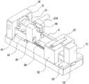
图2是本发明的结构示意图。Figure 2 is a schematic structural diagram of the present invention.
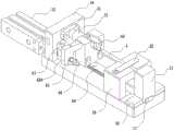
图3也是本发明的结构示意图。FIG. 3 is also a schematic structural diagram of the present invention.
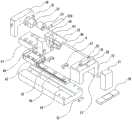
图4是本发明的分解结构示意图。Figure 4 is a schematic diagram of the exploded structure of the present invention.
图5是本发明的刀具结构示意图。FIG. 5 is a schematic diagram of the tool structure of the present invention.
图6是本发明实施例2结构示意图。FIG. 6 is a schematic structural diagram of
图7是本发明实施例2中缓冲防撞单元分解示意图。FIG. 7 is an exploded schematic diagram of the buffer and anti-collision unit in
图8是本发明实施例2中缓冲器结构简图。FIG. 8 is a schematic diagram of a buffer structure in
图9是本发明实施例3中的滑动机构示意图。FIG. 9 is a schematic diagram of a sliding mechanism in
附图标记:1、底座;2、导管定位座;3、转动控制单元;4、导管;5、定转单元;6、切除装置;7、调控器;8、导丝腔;9、通液管;10、限定滑槽;11、限位块;12、推动气缸;20、导管座本体;21、限定槽;22、限定压板;30、固定架;31、驱动安装座;32、驱动元件;33、主轴;34、导管定位轴;35、台阶轴;40、外管;41、内管;42、通液腔;50、定转台;51、定转台;52、转动件; 60、滑动基座;61、滑槽;62、定向滑块;63、横向安装座;64、竖向安装座;65、装配刀槽;66、刀具;67、限位板;620、缓冲防撞单元;621、固定座;622、缓冲器;641、驱动电机;642、推轴;643、推盘;6220、缓冲轴壳;6221、螺栓;6222、定位槽;6223、回位弹簧;6224、缓冲顶杆;6600、红外位移传感器;630、调控把手;660、刀具本体;661、连接件;662、刀刃。Reference numerals: 1. Base; 2. Catheter positioning seat; 3. Rotation control unit; 4. Catheter; 5. Fixed rotation unit; 6. Cutting device; 7. Regulator; 8. Guide wire cavity; Tube; 10. Limiting chute; 11. Limiting block; 12. Pushing cylinder; 20. Catheter base body; 21. Limiting groove; 22. Limiting pressure plate; 30. Fixing frame; 31. Driving mounting seat; 32. Driving element ;33, Main shaft; 34, Catheter positioning shaft; 35, Step shaft; 40, Outer tube; 41, Inner tube; 42, Fluid passage; 50, Fixed turntable; 51, Fixed turntable; Base; 61, Chute; 62, Orientation Slider; 63, Horizontal Mounting Seat; 64, Vertical Mounting Seat; 65, Assembly Slot; 66, Tool; 67, Limiting Plate; 621, fixed seat; 622, buffer; 641, drive motor; 642, push shaft; 643, push plate; 6220, buffer shaft shell; 6221, bolt; 6222, positioning groove; 6223, return spring; 6224, buffer top Rod; 6600, infrared displacement sensor; 630, control handle; 660, tool body; 661, connecting piece; 662, blade.
具体实施方式Detailed ways
下面结合附图与实施例对本发明作进一步详细描述。The present invention will be described in further detail below with reference to the accompanying drawings and embodiments.
实施例1Example 1
如图1至图5所示,一种球囊导管外管切除机构,包括底座1、连接在底座1上的导管定位座2、靠近导管定位座2设置且连接在底座远端上的定转单元5、连接在底座后端的转动控制单元3以及连接在底座1上的切除装置6,所述切除装置6用于切除部分外管40,所述切除装置6在底座1上滑动且滑动距离限定在导管定位座2与转动控制单元3之间;As shown in FIGS. 1 to 5 , a balloon catheter outer tube resection mechanism includes a
所述切除装置6包括滑动基座60、开设在滑动基座60两侧的滑槽61、连接在滑动基座60上且沿滑槽61前后动作的定向滑块62、与定向滑块62上端配合连接的横向安装座63、垂直连接在横向安装座63前端的竖向安装座64、开设在竖向安装座64上的装配刀槽65以及与装配刀槽65配合连接的刀具66,所述滑槽61两端还设有用于限制定向滑块62滑动位置的限位板67;所述装配刀槽65配合刀具66设置为U形,匹配导管4内通液腔42的截面形状,在能够配合刀具66安装的同时,方便对导管4的外管40进行部分切除;所述限位板67能够有效限定定位滑块在滑槽61上两端的滑动位置,提高对切除过程中的控制精度;以上结构根据需求在导管4上标记相应的切除点,进而通过导管定位座2及转动控制单元3对导管4前后段定位,同时定转单元5与导管4的轴端连接定位,然后利用转动控制单元3将导管4移动至通液腔42,再推动切除装置6对应通液腔42位置对导管4的外管40切除至标记点即可,从而方便对外管40定位切割,而且切割效率高,提高了导管外管切除机构的实用性。The cutting device 6 includes a
本实施例中,所述刀具66包括呈U型设置的刀具本体660以及用于连接刀具本体660与装配刀槽65槽壁的连接件661,所述刀具本体660的前端至少有部分伸出竖向安装座64,所述刀具本体660在切除外管40时处于通液腔42的位置,优选的所述连接件661采用定位螺钉,用于刀具本体660与装配刀槽65定位连接,将所述刀具本体660前端从竖向安装座64伸出的刀刃662,能够避免转动控制单元3对导管4前段的切除产生干涉的情况,保证切除机构的合理性;所述刀具本体660底端对应通液腔42设置,是为了在切除外管40时避免切到内管41,提高切除效率,而且刀刃662的外形刚好会与通液腔42对应,在切除时紧贴内管41外壁的位置切削,进而保留了内管41的完整性。In this embodiment, the
本实施例中,所述定转单元包括定转台50以及连接在定转台前侧的转动件52,所述转动件52与导管4后端配合可拆卸连接;所述转动件52设为滚动轴承,同时在导管4尾端套设连接套,同时与滚动轴承配合连接,方便配合导管4在切削时的转动;所述定转台50通过在限定滑槽10内滑动,转动件52与导管4端部直接套接,能够在外管40切除过程中,保证导管4正常转动,为导管4提供了端部的限定位置,避免在切除过程中导管4会产生后退等情况,而且在限定滑槽10的槽端设有限位块11限制定转台50的位置,同时又能为导管4的插接拔出提供活动空间。In this embodiment, the fixed-rotation unit includes a fixed-
本实施例中,所述横向安装座63侧壁连接有调控把手630,所述调控把手630的设置能够在导管4定位后,通过手动前后调控把手630的位置,然后按照需要切除的标记点为基准进行切除即可;也可以在固定架30后侧连接有推动气缸12,所述推动气缸12的前端与横向安装座63连接,通过调控器7控制推动气缸12来回活动,方便对导管4进行切削。In this embodiment, the side wall of the
本实施例中,所述底座1上开设有方便滑动基座60滑动的限定滑槽10,所述限定滑槽10能够对滑动基座60起到导向作用,提高滑动基座60的滑动稳定性。In this embodiment, the
本实施例中,所述转动控制单元3包括固定架30、设置在固定架30内侧的驱动安装座31、与驱动安装座31配合连接的驱动元件32、与驱动元件32配合连接的主轴33以及与主轴33同心设置且延伸至刀具本体660外部的导管定位轴34,所述导管定位轴34前端一体设置有能与内管41插接的台阶轴35,所述台阶轴35穿过刀具66并前伸至靠近导管定位座2的位置;优选的所述驱动元件32设置为电机,所述驱动安装座31对电机进行定位,然后利用电机驱动主轴33同步转动,进而导管4转动,将导管4的通液腔42转动至刀具本体660的位置,从而为下一步的切除作准备;所述导管定位轴34前端的台阶轴35是为了匹配导管4的内管41和外管40进行分别限位,同时方便切除外管40,内管41会套接在台阶轴35上,同时外管40前端限位在导管定位轴34的轴端处,在切除时,刀具本体660被前推切削外管40,实现球囊导管4外腔管的切除过程。In this embodiment, the
本实施例中,所述导管定位座2包括导管座本体20、沿限定滑槽10方向开设在导管座本体20上的限定槽21以及连接在导管座本体20上的限定压板22,所述导管4定位在限位槽内并通过限定压板22限位,所述导管座本体20上的限定槽21能够有效的对导管4后段的横向位移进行限定,同时再利用导管座本体20上的限定压板22对导管4后段的纵向位移进行同步限定,使得导管4被限定在限定槽21内转动,保证了球囊导管4外腔管切除机构运行的稳定性。In this embodiment, the
本实施例中,所述导管定位轴34的外径大于台阶轴35的外径,所述导管4套接在台阶轴35上且靠近台阶轴35的外端抵触在导管定位轴34的尾端,所述导管4通过内管41套接在台阶轴35外壁上,同时抵触在导管定位轴34的尾端面上,从而对导管4的前段位置进行限定。In this embodiment, the outer diameter of the
本实施例中,还包括外接在固定架30上的调控器7,所述调控器7内设有PCB控制板,所述调控器7与电机32配合电性连接,用于控制电机的启闭,同时也能够控制电机32的转速,方便配合切除装置6同步使用。In this embodiment, it also includes a regulator 7 externally connected to the fixing
本实施例的具体工作过程如下:The specific working process of this embodiment is as follows:
首先对外管40的切除位置标记切除点,再将导管4前段插入至导管定位轴34的轴端处,同时导管4后端插入轴套53内,利用限定压板22将导管定位轴34的后段限定在限定槽21内,然后调控器7控制驱动元件32驱动,使得主轴33转动,从而带动导管4转动,使得导管4的通液腔42转动至与刀具本体660的刀刃662处,进而前推调控把手630,横向安装座63会沿着限定滑槽10动作,使得刀具本体660随着纵向安装座被前推至通液腔42切削外管40,当切除至标记点停止推进即可,实现球囊导管4外腔管的切除过程,提高了导管外管切除机构的实用性。First mark the excision point at the excision position of the
实施例2Example 2
如图6至图8所示,所述定向滑块62上连接有缓冲防撞单元620,所述缓冲防撞单元620包括L型设置的固定座621以及锁定在固定座621外侧的缓冲器622,所述缓冲器622的两端分别对应导管定位座2及固定架30内侧设置,所述缓冲器622包括穿过固定座621的缓冲轴壳6220、分设在缓冲轴壳6220上且抵触在固定座621两侧的螺栓622、至少开设在缓冲轴壳6220一端的定位槽6222、设置在定位槽6222内的回位弹簧6223以及轴接在定位槽6222内且抵触在回位弹簧6223前端的缓冲顶杆6224,所述缓冲防撞单元620的设置方便横向安装座63沿定向滑块62动作时进行限位,在缓冲器622抵至导管座本体20后,在缓冲轴壳6220内侧回位弹簧6223的作用下,避免横向安装座63会撞击至导管座本体20上,提高球囊导管外腔管切除机构的使用寿命;所述固定座621设为L型,能够匹配定向滑块52的上平面与侧面,同时进行两面定位,从而增强缓冲防撞单元620与定向滑块62的连接强度。As shown in FIG. 6 to FIG. 8 , the
实施例3Example 3
如图9所示,所述竖向安装座64后侧设有方便控制刀具66前后动作的滑动机构640,所述滑动机构640包括与调控器7配合电性连接的驱动电机641、连接在驱动电机641前端的推轴642以及与推轴642前端连接的推盘643,所述推轴642穿设至竖向安装座64内侧,同时推盘643抵触在竖向安装座64内侧;As shown in FIG. 9 , the rear side of the vertical mounting
所述刀具66后侧开设有定位槽6222,所述推盘643连接在定位槽6222内,同时在所述刀具66的侧壁上连接有红外位移传感器6600,以推盘643抵触在竖向安装座64内侧为零点位置开始移动,配合红外位移传感器6600设定刀具66的位移距离,从而有效控制刀具66切割导管4的精度;The rear side of the
在对导管4进行切除时,刀具66首先配合竖向安装座64动作至导管外管40端部,也就是在需要切除的通液腔42腔口,然后启动驱动电机641控制推盘643推动刀具66动作,使得刀具66前推切削外管40,同时红外线位移传感器6600会通过调控器7设定刀具66位移距离,提升刀具66对外管40的切割精度。When cutting the catheter 4, the
以上内容仅为本发明的较佳实施例,对于本领域的普通技术人员,依据本发明的思想,在具体实施方式及应用范围上均会有改变之处,本说明书内容不应理解为对本发明的限制。The above contents are only preferred embodiments of the present invention. For those of ordinary skill in the art, according to the idea of the present invention, there will be changes in the specific embodiments and application scope. limits.
Claims (10)
Translated fromChinesePriority Applications (1)
| Application Number | Priority Date | Filing Date | Title |
|---|---|---|---|
| CN202010220810.3ACN111376322A (en) | 2020-03-26 | 2020-03-26 | A Balloon Catheter Outer Tube Removal Mechanism |
Applications Claiming Priority (1)
| Application Number | Priority Date | Filing Date | Title |
|---|---|---|---|
| CN202010220810.3ACN111376322A (en) | 2020-03-26 | 2020-03-26 | A Balloon Catheter Outer Tube Removal Mechanism |
Publications (1)
| Publication Number | Publication Date |
|---|---|
| CN111376322Atrue CN111376322A (en) | 2020-07-07 |
Family
ID=71220077
Family Applications (1)
| Application Number | Title | Priority Date | Filing Date |
|---|---|---|---|
| CN202010220810.3APendingCN111376322A (en) | 2020-03-26 | 2020-03-26 | A Balloon Catheter Outer Tube Removal Mechanism |
Country Status (1)
| Country | Link |
|---|---|
| CN (1) | CN111376322A (en) |
Cited By (3)
| Publication number | Priority date | Publication date | Assignee | Title |
|---|---|---|---|---|
| CN113546278A (en)* | 2021-08-10 | 2021-10-26 | 杨晶 | External intervention catheter windowing equipment |
| CN115025366A (en)* | 2022-07-01 | 2022-09-09 | 惠州市顺美医疗科技有限公司 | Medical catheter and rotary cutting method thereof |
| CN115194886A (en)* | 2022-07-14 | 2022-10-18 | 惠州市顺美医疗科技有限公司 | Advanced small catheter and preparation method thereof |
Citations (5)
| Publication number | Priority date | Publication date | Assignee | Title |
|---|---|---|---|---|
| CN1230914A (en)* | 1996-09-16 | 1999-10-06 | 萨考斯公司 | Method and apparatus for forming cuts in catheters, guidewires and the like |
| JP2001096421A (en)* | 1999-09-28 | 2001-04-10 | Sango Co Ltd | Pipe cutter |
| CN208788729U (en)* | 2018-08-28 | 2019-04-26 | 杭州富通通信技术股份有限公司 | A casing bulge repair device |
| CN110653866A (en)* | 2019-10-30 | 2020-01-07 | 苏州超硕凡塑料制品有限公司 | Rotatable plastic pipe cutting device |
| CN211993097U (en)* | 2020-03-26 | 2020-11-24 | 宁波韦科医疗科技有限公司 | Cutting mechanism for outer tube of balloon catheter |
- 2020
- 2020-03-26CNCN202010220810.3Apatent/CN111376322A/enactivePending
Patent Citations (5)
| Publication number | Priority date | Publication date | Assignee | Title |
|---|---|---|---|---|
| CN1230914A (en)* | 1996-09-16 | 1999-10-06 | 萨考斯公司 | Method and apparatus for forming cuts in catheters, guidewires and the like |
| JP2001096421A (en)* | 1999-09-28 | 2001-04-10 | Sango Co Ltd | Pipe cutter |
| CN208788729U (en)* | 2018-08-28 | 2019-04-26 | 杭州富通通信技术股份有限公司 | A casing bulge repair device |
| CN110653866A (en)* | 2019-10-30 | 2020-01-07 | 苏州超硕凡塑料制品有限公司 | Rotatable plastic pipe cutting device |
| CN211993097U (en)* | 2020-03-26 | 2020-11-24 | 宁波韦科医疗科技有限公司 | Cutting mechanism for outer tube of balloon catheter |
Cited By (3)
| Publication number | Priority date | Publication date | Assignee | Title |
|---|---|---|---|---|
| CN113546278A (en)* | 2021-08-10 | 2021-10-26 | 杨晶 | External intervention catheter windowing equipment |
| CN115025366A (en)* | 2022-07-01 | 2022-09-09 | 惠州市顺美医疗科技有限公司 | Medical catheter and rotary cutting method thereof |
| CN115194886A (en)* | 2022-07-14 | 2022-10-18 | 惠州市顺美医疗科技有限公司 | Advanced small catheter and preparation method thereof |
Similar Documents
| Publication | Publication Date | Title |
|---|---|---|
| CN111376322A (en) | A Balloon Catheter Outer Tube Removal Mechanism | |
| JP6737829B2 (en) | Biopsy device | |
| CN111790044A (en) | A separate ablation catheter and sheath combined drive device | |
| CN208677514U (en) | Disposable blood vessel punch | |
| CN211993097U (en) | Cutting mechanism for outer tube of balloon catheter | |
| CN203861292U (en) | One-time intra-cavity incision anastomat rotary joint assembly | |
| CN212631403U (en) | Combined driving device for separated ablation catheter and sheath catheter | |
| CN115572669A (en) | In-vitro blastocyst biopsy sampling device and operation method thereof | |
| CN212089662U (en) | Bone resection device | |
| US20240285267A1 (en) | Motorized end-cut biopsy device with disposable syringe and reusable handpiece | |
| CN212089661U (en) | Bone resection device | |
| CN112792422B (en) | Upper needle and lower needle device for electric discharge machining three-edged needle | |
| CN115444515A (en) | An intravascular rotational atherectomy device | |
| CN114711954A (en) | Easily adjustable telescopic smoking knife | |
| CN117322961B (en) | Uropoiesis surgery protector | |
| CN113693642A (en) | Gynecological tumor sample tissue sampling device | |
| CN106821461B (en) | Suction cutting tube | |
| CN221712127U (en) | Ultrasonic intervention puncture device | |
| CN223395362U (en) | Automatic cutting device for medical catheter | |
| CN112454804B (en) | Production equipment and manufacturing method of puncture needle ultrasonic area | |
| CN119897919A (en) | Three-way valve PICC catheter incision device | |
| CN120678496A (en) | A catheter device for removing vascular thrombus | |
| CN213283232U (en) | Artery blood vessel plaque rotary-cut system based on self-propelled control | |
| CN222130217U (en) | A blood vessel punch | |
| CN212044986U (en) | Cutting device for spherical bag blank |
Legal Events
| Date | Code | Title | Description |
|---|---|---|---|
| PB01 | Publication | ||
| PB01 | Publication | ||
| SE01 | Entry into force of request for substantive examination | ||
| SE01 | Entry into force of request for substantive examination | ||
| RJ01 | Rejection of invention patent application after publication | ||
| RJ01 | Rejection of invention patent application after publication | Application publication date:20200707 |