CN111374810A - Coated vascular stent with improved wall-adhering performance - Google Patents
Coated vascular stent with improved wall-adhering performanceDownload PDFInfo
- Publication number
- CN111374810A CN111374810ACN201910255852.8ACN201910255852ACN111374810ACN 111374810 ACN111374810 ACN 111374810ACN 201910255852 ACN201910255852 ACN 201910255852ACN 111374810 ACN111374810 ACN 111374810A
- Authority
- CN
- China
- Prior art keywords
- annular
- wave
- stent
- proximal end
- film
- Prior art date
- Legal status (The legal status is an assumption and is not a legal conclusion. Google has not performed a legal analysis and makes no representation as to the accuracy of the status listed.)
- Granted
Links
Images


Classifications
- A—HUMAN NECESSITIES
- A61—MEDICAL OR VETERINARY SCIENCE; HYGIENE
- A61F—FILTERS IMPLANTABLE INTO BLOOD VESSELS; PROSTHESES; DEVICES PROVIDING PATENCY TO, OR PREVENTING COLLAPSING OF, TUBULAR STRUCTURES OF THE BODY, e.g. STENTS; ORTHOPAEDIC, NURSING OR CONTRACEPTIVE DEVICES; FOMENTATION; TREATMENT OR PROTECTION OF EYES OR EARS; BANDAGES, DRESSINGS OR ABSORBENT PADS; FIRST-AID KITS
- A61F2/00—Filters implantable into blood vessels; Prostheses, i.e. artificial substitutes or replacements for parts of the body; Appliances for connecting them with the body; Devices providing patency to, or preventing collapsing of, tubular structures of the body, e.g. stents
- A61F2/82—Devices providing patency to, or preventing collapsing of, tubular structures of the body, e.g. stents
- A61F2/86—Stents in a form characterised by the wire-like elements; Stents in the form characterised by a net-like or mesh-like structure
- A61F2/90—Stents in a form characterised by the wire-like elements; Stents in the form characterised by a net-like or mesh-like structure characterised by a net-like or mesh-like structure
- A61F2/91—Stents in a form characterised by the wire-like elements; Stents in the form characterised by a net-like or mesh-like structure characterised by a net-like or mesh-like structure made from perforated sheets or tubes, e.g. perforated by laser cuts or etched holes
- A61F2/915—Stents in a form characterised by the wire-like elements; Stents in the form characterised by a net-like or mesh-like structure characterised by a net-like or mesh-like structure made from perforated sheets or tubes, e.g. perforated by laser cuts or etched holes with bands having a meander structure, adjacent bands being connected to each other
Landscapes
- Health & Medical Sciences (AREA)
- Engineering & Computer Science (AREA)
- Biomedical Technology (AREA)
- Heart & Thoracic Surgery (AREA)
- Life Sciences & Earth Sciences (AREA)
- Cardiology (AREA)
- Oral & Maxillofacial Surgery (AREA)
- Transplantation (AREA)
- Physics & Mathematics (AREA)
- Vascular Medicine (AREA)
- Optics & Photonics (AREA)
- Animal Behavior & Ethology (AREA)
- General Health & Medical Sciences (AREA)
- Public Health (AREA)
- Veterinary Medicine (AREA)
- Media Introduction/Drainage Providing Device (AREA)
- Prostheses (AREA)
Abstract
Translated fromChinese
Description
Translated fromChinese技术领域technical field
本发明涉及可植入血管技术领域,尤其涉及一种改进贴壁性能的覆膜血管支架,所述覆膜血管支架利用经皮穿刺的方式通过输送导管将其输送到血管病变位置,将血管支架释放在血管病变位置并膨胀形成血管腔,以起到重塑血管的作用。The present invention relates to the technical field of implantable blood vessels, and in particular to a covered vascular stent with improved adherence performance. Released at the site of vascular lesions and expanded to form a vascular lumen to remodel blood vessels.
背景技术Background technique
目前可以采用微创伤介入术治疗血管疾病,此类方法对病人的创伤小,安全性高,有效性高,因此受到医生与患者的肯定,已成为血管疾病的重要治疗方法。介入性治疗方法是指用输送系统将血管支架植入患者血管病变段,植入的血管支架通过扩张可以支撑狭窄闭塞段血管或封堵血管夹层破口,减少血管弹性回缩及再塑形,保持管腔血流通畅,还具有预防再狭窄的作用。At present, micro-invasive interventional surgery can be used to treat vascular diseases. Such methods are less traumatic to patients, have high safety and high effectiveness, so they are affirmed by doctors and patients and have become an important treatment method for vascular diseases. Interventional therapy refers to the use of a delivery system to implant a vascular stent into a patient's vascular disease segment. The implanted vascular stent can support the narrowed and occluded segment of the blood vessel or block the vascular dissection rupture through expansion, reducing the elastic retraction and reshaping of the blood vessel. Keeping lumen blood flow unobstructed also has the effect of preventing restenosis.
覆膜血管支架是目前应用较广的一种血管支架,能够隔绝血流和有病变的血管,从而免除血管破裂的致命性风险。然而,现有的覆膜血管支架存在内漏的缺点,所述内漏是指覆膜血管支架置入血管后,在覆膜血管支架腔外且在被此覆膜血管支架所治疗的动脉瘤腔及邻近血管腔内出现持续性血流的现象。内漏的后果:(1)瘤腔继续增大,最终促使主动脉瘤破裂或转向传统手术。(2)将瘤腔内血栓冲挤入正常血流内引起远端动脉栓塞。Covered vascular stent is a widely used vascular stent, which can isolate blood flow and diseased blood vessels, thereby avoiding the fatal risk of blood vessel rupture. However, the existing covered vascular stents have the disadvantage of endoleak, which refers to an aneurysm outside the lumen of the covered vascular stent and treated by the covered vascular stent after the covered vascular stent is inserted into the blood vessel. Persistent blood flow in the lumen and adjacent vessel lumen. Consequences of endoleak: (1) The aneurysm cavity continues to grow, eventually prompting rupture of the aortic aneurysm or turning to traditional surgery. (2) The thrombus in the tumor cavity is pushed into the normal blood flow to cause distal arterial embolism.
内漏按漏血来源分为4种类型:因覆膜血管支架与自体血管无法紧密帖合而形成内漏,包括近端和远端接口;漏血来自侧支血管血液的返流,包括腰动脉、肠系膜下动脉、骶中动脉、髂内动脉等;因覆膜血管支架自身接口无法紧密结合或覆膜血管支架破裂而形成内漏;经覆盖支架的覆膜编织缝隙形成的渗漏。其中覆膜血管支架与自体血管无法紧密帖合而形成内漏常见原因:(1)血管成角:动脉瘤的不断扩张、动脉壁结构的改变以及血液动力学变化使血管发生扭曲,这种扭曲常发生在动脉瘤的近端颈部血管及髂动脉。当支架锚定部位处于近、远端血管成角区域时,血管成角可造成支架放置后不能与血管紧密贴合。成角越大越易造成漏血。(2)瘤颈过短:近端瘤颈过短造成支架不能与自体血管紧密贴合是引起近端内漏的另一重要原因。(3)颈部血管形态:近端颈部血管粗细均匀对覆膜血管支架的牢固锚定非常重要。(4)血管钙化:钙化是动脉瘤常见病理改变,当钙化斑块位于覆膜血管支架的锚定区域可造成支架不能与自体血管紧密贴合。(5)覆膜血管支架直径选择错误:当近、远端锚定部位支架直径选择过小可造成内漏。(6)覆膜血管支架塑型:覆膜血管支架置入后一定时期内的再塑型是发生继发性内漏的重要因素。覆膜血管支架锚定部位不充分造成覆膜血管支架放置后稳定性差是导致塑型后内漏的主要原因。上述因素常常同时存在。目前内漏处理方法一般为球囊扩张或附加支架型血管;但目前的处理方法仍然无法完全消除内漏。Endoleak is divided into 4 types according to the source of blood leakage: endoleak is formed because the covered vascular stent cannot be closely attached to the native blood vessel, including proximal and distal interfaces; blood leakage comes from the backflow of blood from collateral vessels, including lumbar Arterial, inferior mesenteric artery, middle sacral artery, internal iliac artery, etc.; endoleak is formed due to the failure of the self-interface of the covered vascular stent or the rupture of the covered vascular stent; the leakage formed by the covered braided gap of the stent. Among them, the covered vascular stent cannot be closely attached to the autologous blood vessel, and the common causes of endoleak are: (1) Blood vessel angulation: the continuous expansion of the aneurysm, the changes in the structure of the arterial wall and the changes in the hemodynamics cause the blood vessels to be distorted. It usually occurs in the proximal neck vessels and iliac arteries of aneurysms. When the anchoring site of the stent is in the angulated area of the proximal and distal blood vessels, the angulation of the blood vessel may cause the stent to be unable to closely fit the blood vessel after placement. The larger the angle, the more likely to cause blood leakage. (2) Too short aneurysm neck: Another important cause of proximal endoleak is that the proximal end of the aneurysm neck is too short and the stent cannot fit closely with the autologous blood vessel. (3) Morphology of the neck blood vessels: The uniform thickness of the proximal neck blood vessels is very important for the firm anchoring of the covered vascular stent. (4) Vascular calcification: Calcification is a common pathological change in aneurysms. When the calcified plaque is located in the anchoring area of the covered vascular stent, the stent cannot be closely attached to the native blood vessel. (5) Wrong selection of the diameter of the covered vascular stent: When the diameter of the stent at the proximal and distal anchoring sites is too small, endoleak may be caused. (6) Remodeling of covered stents: Remodeling within a certain period of time after implantation of covered stents is an important factor for the occurrence of secondary endoleaks. The poor stability of the stent-graft after placement due to the insufficient anchoring site of the stent-graft is the main reason for endoleak after molding. The above factors often coexist. The current treatment methods for endoleaks are generally balloon dilation or stent-attached vessels; however, the current treatment methods still cannot completely eliminate endoleaks.
发明内容SUMMARY OF THE INVENTION
本发明的目的在于提供一种能改进贴壁性能,以消除内漏的覆膜血管支架。The purpose of the present invention is to provide a covered vascular stent which can improve the adherence performance to eliminate endoleak.
为了解决上述技术问题,本发明提供了一种改进贴壁性能的覆膜血管支架,其包括覆膜、设置于所述覆膜上的主体支撑架,以及设置于所述覆膜的近端和/或远端的扩撑定位件,在所述覆膜血管支架受到径向挤压后,所述扩撑定位件的径向支撑力能维持覆膜的近端和/或远端的完全扩张。In order to solve the above technical problems, the present invention provides a covered vascular stent with improved adherence performance, which comprises a film, a main body support frame arranged on the film, and a proximal end and a stent provided on the film. / or the distal expansion and positioning member, after the stent-graft is radially compressed, the radial support force of the expansion and positioning member can maintain the complete expansion of the proximal and/or distal ends of the membrane .
本发明提供的覆膜血管支架通过在覆膜的近端和/或远端设置所述扩撑定位件,所述扩撑定位件具有径向的支撑力。因此,当所述覆膜血管支架在植入的血管内展开后,所述扩撑定位件的径向支撑力能扩撑所述覆膜的近端和/或远端贴合于所述血管的内壁,以维持所述覆膜的近端和/或远端与所述血管的内壁的密封贴合,从而使所述覆膜与所述血管的内壁之间没有间隙,避免内漏。In the stent-grafted blood vessel provided by the present invention, the expansion and expansion positioning member is provided at the proximal end and/or the distal end of the coating, and the expansion and expansion positioning member has a radial supporting force. Therefore, after the stent-graft is deployed in the implanted blood vessel, the radial support force of the expansion and positioning member can expand and expand the proximal end and/or the distal end of the stent to adhere to the blood vessel The inner wall of the membrane can maintain the sealing fit between the proximal end and/or the distal end of the membrane and the inner wall of the blood vessel, so that there is no gap between the membrane and the inner wall of the blood vessel to avoid endoleak.
附图说明Description of drawings
为了更清楚地说明本发明实施例的技术方案,下面将对实施方式中所需要使用的附图作简单地介绍,显而易见地,下面描述中的附图是本发明一些实施方式,对于本领域普通技术人员来讲,在不付出创造性劳动的前提下,还可以根据这些附图获得其他的附图。In order to illustrate the technical solutions of the embodiments of the present invention more clearly, the following briefly introduces the accompanying drawings used in the implementation manner. As far as technical personnel are concerned, other drawings can also be obtained based on these drawings without any creative effort.
图1是本发明第一实施例提供的覆膜血管支架的结构示意图。FIG. 1 is a schematic structural diagram of the covered stent provided by the first embodiment of the present invention.
图2是图1中的II部分的放大图。FIG. 2 is an enlarged view of part II in FIG. 1 .
图3是本发明第二实施例提供的覆膜血管支架的结构示意图。FIG. 3 is a schematic structural diagram of the covered stent provided by the second embodiment of the present invention.
图4是本发明第三实施例提供的覆膜血管支架的结构示意图。FIG. 4 is a schematic structural diagram of the covered stent provided by the third embodiment of the present invention.
图5是图4中的V部分的放大图。FIG. 5 is an enlarged view of the portion V in FIG. 4 .
图6是图4中的VI部分的放大图。FIG. 6 is an enlarged view of part VI in FIG. 4 .
图7是本发明第四实施例提供的覆膜血管支架的结构示意图。FIG. 7 is a schematic structural diagram of the covered stent provided by the fourth embodiment of the present invention.
图8是图7中的VIII部分的放大图。FIG. 8 is an enlarged view of part VIII in FIG. 7 .
图9是本发明第五实施例提供的覆膜血管支架的结构示意图。FIG. 9 is a schematic structural diagram of the covered stent provided by the fifth embodiment of the present invention.
图10是本发明第六实施例提供的覆膜血管支架的结构示意图。FIG. 10 is a schematic structural diagram of the covered stent provided by the sixth embodiment of the present invention.
图11是本发明第七实施例提供的覆膜血管支架的结构示意图。FIG. 11 is a schematic structural diagram of the covered stent provided by the seventh embodiment of the present invention.
图12是图11中的XII部分的放大图。FIG. 12 is an enlarged view of part XII in FIG. 11 .
图13是本发明第八实施例提供的覆膜血管支架的结构示意图。FIG. 13 is a schematic structural diagram of the covered stent provided by the eighth embodiment of the present invention.
图14是图13中的XIV部分的放大图。FIG. 14 is an enlarged view of part XIV in FIG. 13 .
图15是本发明第九实施例提供的覆膜血管支架的结构示意图。FIG. 15 is a schematic structural diagram of the covered stent provided by the ninth embodiment of the present invention.
图16是图15中的XVI部分的放大图。FIG. 16 is an enlarged view of part XVI in FIG. 15 .
具体实施方式Detailed ways
下面将结合本发明实施例中的附图,对本发明实施例中的技术方案进行清楚、完整地描述,显然,所描述的实施例仅仅是本发明一部分实施例,而不是全部的实施例。基于本发明中的实施例,本领域普通技术人员在没有付出创造性劳动前提下所获得的所有其他实施例,都属于本发明保护的范围。The technical solutions in the embodiments of the present invention will be clearly and completely described below with reference to the accompanying drawings in the embodiments of the present invention. Obviously, the described embodiments are only a part of the embodiments of the present invention, but not all of the embodiments. Based on the embodiments of the present invention, all other embodiments obtained by those of ordinary skill in the art without creative efforts shall fall within the protection scope of the present invention.
此外,以下各实施例的说明是参考附加的图示,用以例示本发明可用以实施的特定实施例。本发明中所提到的方向用语,例如,“上”、“下”、“前”、“后”、“左”、“右”、“内”、“外”、“侧面”等,仅是参考附加图式的方向,因此,使用的方向用语是为了更好、更清楚地说明及理解本发明,而不是指示或暗指所指的装置或元件必须具有特定的方位、以特定的方位构造和操作,因此不能理解为对本发明的限制。Furthermore, the following descriptions of the various embodiments refer to the accompanying drawings to illustrate specific embodiments in which the invention may be practiced. Directional terms mentioned in the present invention, such as "up", "down", "front", "rear", "left", "right", "inside", "outside", "side", etc., only Reference is made to the directions of the accompanying drawings, therefore, the directional terms used are for better and clearer description and understanding of the present invention, rather than indicating or implying that the device or element referred to must have a specific orientation, in a specific orientation construction and operation, and therefore should not be construed as limiting the invention.
在本发明的描述中,本发明所述“近端”是指靠近心脏位置的一端,所述“远端”为远离心脏位置的一端。本发明中所述的高、低是相对于覆膜而言,超出覆膜的端面称为高,未超出覆膜端面的称为低,该定义只是为了表述方便,并不能理解为对本发明的限制。In the description of the present invention, the "proximal end" of the present invention refers to the end close to the position of the heart, and the "distal end" refers to the end away from the position of the heart. The high and low mentioned in the present invention are relative to the film. The end face that exceeds the film is called high, and the end face that does not exceed the end face of the film is called low. This definition is only for the convenience of expression, and should not be understood as a limit.
请参阅图1及图2,图1是本发明第一实施例提供的覆膜血管支架的结构示意图;图2是图1中的II部分的放大图。本发明提供一种改进贴壁性能的覆膜血管支架100,其包括管状的覆膜20、设置于所述覆膜20上的主体支撑架40,以及设置于所述覆膜20的近端和/或远端的扩撑定位件60。在所述覆膜血管支架100植入血管内后,即所述膜支架100受到扩张的径向挤压,所述扩撑定位件60的径向支撑力能维持覆膜20的近端和/或远端完全扩张,从而使覆膜20与所述血管的内壁的密封贴合,以避免内漏发生。本实施例中,所述扩撑定位件60的径向支撑力能维持覆膜20的近端和/或远端呈完整的圆环结构。Please refer to FIG. 1 and FIG. 2 , FIG. 1 is a schematic structural diagram of the stent-graft provided by the first embodiment of the present invention; FIG. 2 is an enlarged view of part II in FIG. 1 . The present invention provides a stent-
所述扩撑定位件60为自膨胀式的环状定位架,所述环状定位架能径向扩展,所述覆膜20固定于所述环状定位架上。所述环状定位架可以设置于所述覆膜20的近端和/或远端,所述覆膜20的近端和/或远端固定于所述环状定位架的外表面和/或内表面。本实施例中,所述扩撑定位件60设置于所述覆膜20的近端,所述覆膜20的近端面延伸至所述扩撑定位件60上,即所述覆膜20的近端至少有一部分与所述扩撑定位件60重叠。优选的,所述覆膜20的近端面与所述扩撑定位件60的近端面齐平。在所述覆膜血管支架100展开的状态下,所述扩撑定位件60的径向支撑力扩撑所述覆膜20贴合于血管的内壁,使覆膜20与所述血管的内壁之间密封,防止内漏。The expansion and
在其他实施例中,所述覆膜20的近端面可以高出所述扩撑定位件60的近端面,并将高出所述扩撑定位件60的近端面的覆膜20向内或向外翻折后,再连接于所述扩撑定位件60。In other embodiments, the proximal end surface of the covering
本发明提供的覆膜血管支架100通过在覆膜20的近端和/或远端设置所述扩撑定位件60,所述扩撑定位件60具有径向的支撑力。因此,当所述覆膜血管支架100在植入的血管内展开后,所述扩撑定位件60的径向支撑力能扩撑所述覆膜20的近端和/或远端贴合于所述血管的内壁,以维持所述覆膜20的近端和/或远端与所述血管的内壁的密封贴合,从而使所述覆膜20与所述血管的内壁之间没有间隙,避免内漏。In the stent-
所述覆膜20的横端面的形状是与血管配合的圆形或椭圆形,所述覆膜20采用涤纶布、聚四氟乙烯、聚酯纤维或其他医用高分子材料制成。The shape of the transverse end surface of the covering
所述主体支撑架40为自膨胀式的支撑骨架,所述支撑骨架可以是弹性的金属支撑骨架或弹性的非金属如弹性圈、高分子材料的支撑骨架,所述主体支撑架40也可以通过机械膨胀的方式恢复初始形状,例如球囊扩张膨胀。本实施例中,所述支撑骨架为镍钛合金支架,当所述支撑骨架通过鞘管输送时,所述支撑骨架的直径可收缩至较小状态以便在鞘管中输送;当主体支撑架40在病变血管内释放时,所述主体支撑架40可自动膨胀至所需形状尺寸,以使所述主体支撑架40能支撑于病变血管的内壁上,所述主体支撑架40对所述血管的内壁产生径向的支撑作用。本实施例中,所述主体支撑架40是采用金属丝编织而成的裸支架。The main
所述主体支撑架40可以是径向压缩的网格状结构、杆状结构、框架结构或软性可折叠结构等,也可以采用金属管切割后形成网格状或者框架结构。所述金属丝可为镍钛合金、钴铬合金、不锈钢或其他生物相容性良好的金属材料,优选超弹性形状记忆合金镍钛丝,其制作工艺与传统支架制作工艺相同,在此不再赘述。The main
如图1所示,所述主体支撑架40包括若干个Z形或正弦波形的波形支撑杆42构成,这些波形支撑杆42通过医用缝合线缝合或通过医用胶水贴接在覆膜20内表面或者外表面,或者通过热压的方式固定在两层覆膜20之间,这些波形支撑杆42沿所述主体支撑架40的轴向间隔排列。每一波形支撑杆42可以是等波支撑杆或高低波支撑杆等,所述等波支撑杆是指波形支撑杆42上的各个波峰的高度相同,且各个波谷的高度也相同,即,各个波峰及各个波谷分别在同一平面上。所述高低波支撑杆是指波形支撑杆42上的各个波峰的高度不相同,各个波谷的高度也可以不相同。As shown in FIG. 1 , the main
本实施例中,所述主体支撑架40由若干个等波支撑杆轴向间隔排列而成,所述波形支撑杆42采用0.5mm直径的镍钛丝编织而成,正弦波数量可以是任意数量,波形支撑杆42的垂直高度可以是任意高度。每一波形支撑杆42通过缝线缝合在覆膜20上,所述缝线可以沿着每一波形支撑杆42的波形走向而伴随整个主体支撑架40,所述缝线优选高分子缝合线,所述高分子缝合线可以是PTFE或者PET缝合线。In this embodiment, the main
每一波形支撑杆42由若干个支撑单元首尾相接组成,每个所述支撑单元包括一波峰421、一波谷423,以及连接于所述波峰421与所述波谷423之间的一波杆425。每一个波形支撑杆42可以通过一条超弹性镍钛丝弯曲而成,每一个波形支撑杆42上设置有一连接套,所述连接套将所述波形支撑杆42相对的两端连接,即,所述波形支撑杆42相对的两端均收纳于所述连接套内,然后再通过机械压紧或者焊接方式将镍钛丝的两个端固定在连接套的内部。Each
在本实施例中,相邻近的两个波形支撑杆42之间的波峰421与波峰421相对应,波谷423与波谷423相对应。In this embodiment, the wave crests 421 between the two adjacent
在其他实施例中,所述波形支撑杆42也可以是高低波支撑杆。In other embodiments, the
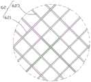
本实施例中的扩撑定位件60为环状编织网62,所述环状编织网62设置于所述覆膜20的近端,所述环状编织网62由相互交错的经线丝621及纬线丝623编织而成;所述环状编织网62由具有弹性的记忆合金丝编织而成,即所述经线丝621及纬线丝623均由具有弹性的记忆合金丝编织而成。所述环状编织网62包括近端面625及远端面626,所述覆膜20固定于所述环状编织网62上,所述覆膜20的近端面位于所述环状编织网62的近端面625与远端面626之间。所述环状编织网62可以由一根具有弹性的记忆合金丝编织而成,也可以由若干根具有弹性的记忆合金丝编织而成,所述记忆合金丝优选为镍钛丝。所述镍钛丝的丝径小于0.1mm。In this embodiment, the expansion and
所述环状编织网62的编织网孔可以是菱形、矩形或多边形等其他形状。The woven mesh of the annular woven
所述环状编织网62可以通过缝合、热压或胶接的方式连接于所述覆膜20的内表面或者外表面上,以使所述环状编织网62与所述覆膜20能紧密固定。The endless woven
在其他实施例中,所述覆膜20的近端面可以与所述环状编织网62的近端面齐平。In other embodiments, the proximal end surface of the
在其他实施例中,所述覆膜20的近端面可以高出所述环状编织网62的近端面,并将高出所述环状编织网62的近端面的覆膜20向内或向外翻折后,再连接于所述环状编织网62。In other embodiments, the proximal end surface of the covering
在其他实施例中,所述环状编织网62的近端边缘和/或远端边缘上设置有显影标记,所述显影标记可以是连续或间断地缠绕于所述环状编织网62的近端边缘和/或远端边缘上的显影丝,或者是连续或者间隔地设置于所述环状编织网62的近端边缘和/或远端边缘上的点式显影标记等显影件;所述显影件材料可以采用不透X射线性能好、耐腐蚀性强、生物相容性好的材料制成,包括但不限于金、铂、钽、锇、铼、钨、铱、铑等材料或这些金属的合金或复合物。In other embodiments, the proximal edge and/or the distal edge of the endless woven
在其他实施例中,覆膜20的近端边缘或远端边缘上设置有显影标记。In other embodiments, a visualization marker is provided on the proximal edge or the distal edge of the
请参阅图3,图3是本发明第二实施例提供的覆膜血管支架的结构示意图。本发明的第二实施例提供的覆膜血管支架的结构与第一实施例的结构相似,不同之处在于:在第二实施例中,覆膜20的近端及远端均设置有扩撑定位件60,具体的,所述覆膜20的近端及远端分别设置有环状编织网62,所述覆膜20的近端连接于所述覆膜20的近端的环状编织网62上,覆膜20的远端连接于所述覆膜20的远端的环状编织网62上。所述覆膜20的近端面位于近端的环状编织网62的近端面625与远端面626之间,优选所述覆膜20的近端面与所述近端的环状编织网62的近端面625齐平;所述覆膜20的远端面位于远端的环状编织网62的近端面625与远端面626之间,优选所述覆膜20的远端面与远端的环状编织网62的远端面626齐平。Please refer to FIG. 3 . FIG. 3 is a schematic structural diagram of a stent-grafted vessel provided by a second embodiment of the present invention. The structure of the covered vascular stent provided by the second embodiment of the present invention is similar to that of the first embodiment, the difference is that in the second embodiment, the proximal end and the distal end of the covering 20 are provided with expansion struts The positioning
在其他实施例中,覆膜20的近端的环状编织网62的近端边缘和/或远端边缘上设置有显影标记;覆膜20的远端的环状编织网62的近端边缘和/或远端边缘上也可以设置有显影标记。In other embodiments, the proximal edge and/or the distal edge of the annular woven
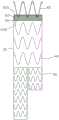
请一并参阅图4至图6,本发明的第三实施例提供的覆膜血管支架的结构与第一实施例的结构相似,不同之处在于:在第三实施例中,扩撑定位件60还包括环状波形扩撑杆65,所述环状波形扩撑杆65包括若干个Z形或正弦波形的支撑单元首尾相接组成,每个所述支撑单元包括一波峰651、一波谷653,以及连接于所述波峰651与所述波谷653之间的一波杆655。所述环状波形扩撑杆65由超弹性镍钛通过激光一体切割而成。所述环状波形扩撑杆65的波谷653连接于所述环状编织网62上,在覆膜血管支架植入对应的血管内并展开时,所述环状波形扩撑杆65展开带动所述环状编织网62,使所述环状编织网62与所述环状波形扩撑杆65一并展开,通过两者的径向支撑力一并将覆膜20紧密地贴合于所述血管的内壁,使覆膜20与血管的内壁之间密封贴合,防止内漏;由于所述主体支撑架40、环状编织网62及所述环状波形扩撑杆65展开后均对所述血管的内壁有径向的扩撑力,能将覆膜血管支架稳定的定位于血管的内壁上,防止所述覆膜血管支架位移。Please refer to FIG. 4 to FIG. 6 together, the structure of the stent-graft provided by the third embodiment of the present invention is similar to that of the first embodiment, the difference is: 60 also includes a ring-shaped
本实施例中,所述环状波形扩撑杆65具有5个波峰和波谷,环状波形扩撑杆65的壁厚为0.4mm,波杆宽度为0.45mm,使环状波形扩撑杆65具有较大的径向支撑强度。环状编织网62的近端边缘与覆膜20的近端边缘平齐,环状波形扩撑杆65的波谷连接于所述环状编织网62邻近近端边缘处。由于环状编织网62本身具有超弹性和一定的刚度,另外环状波形扩撑杆65的径向支撑力通过环状编织网62为中间体均匀作用在覆膜20的近端,使覆膜20的近端边缘与血管壁完全贴合,大大提高了覆膜血管支架100的贴壁性能,防止内漏发生。In this embodiment, the annular
如图5所示,所述环状波形扩撑杆65与所述环状编织网62之间通过医用缝合线缝合连接或医用胶水连接。具体的,所述环状波形扩撑杆65的波谷653与所述环状编织网62相交处通过医用缝合线以波谷653为路径螺旋缠绕一周,所述缝合线将缝合路径上的覆膜20和环状编织网62与环状波形扩撑杆65一并缝合;或者在环状波形扩撑杆65的波谷653与所述环状编织网62相交处通过医用胶水将环状波形扩撑杆65的波谷653、覆膜20及环状编织网62胶合于一体。As shown in FIG. 5 , the annular
如图6所示,所述环状波形扩撑杆65上设置有锚定倒刺656,这些锚定倒刺656沿所述环状波形扩撑杆65的周向设置至少一圈,所述覆膜血管支架100植入后,锚定倒刺656能剌入血管的内壁以进一步锚定所述覆膜血管支架100,采用锚定倒刺656锚定稳定性更好,能防止覆膜血管支架100脱落。As shown in FIG. 6 , anchoring
本实施例中,锚定倒刺656设置于所述环状波形扩撑杆65的每一个波峰651上,所述波峰651相对的两个内侧面分别倾斜地朝向环状编织网62延伸一锚定倒刺656。In this embodiment, the anchoring
在其他实施例中,所述环状波形扩撑杆65的波杆655和/或波谷653上均可以设置锚定倒刺656。In other embodiments, anchoring
在其他实施例中,所述环状波形扩撑杆65及环状编织网62上均可以设置锚定倒剌。In other embodiments, anchoring bars may be provided on both the annular wave-shaped expanding struts 65 and the annular woven
在其他实施例中,覆膜20的远端也可以一并设置环状编织网62及环状波形扩撑杆65。具体的,环状波形扩撑杆65的各波峰连接于所述环状编织网62上,所述环状波形扩撑杆65除波峰外的其他部分外露出所述覆膜20的远端面。远端的环状波形扩撑杆65上也可以设置有锚定倒刺656。覆膜20的远端面延伸至远端的环状波形扩撑杆65的波峰上。In other embodiments, the distal end of the
在其他实施例中,环状波形扩撑杆65上沿周向可以设置至少一圈的显影标记。In other embodiments, at least one circle of developing marks may be provided on the annular wave-shaped expanding
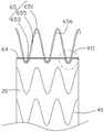
请一并参阅图7及图8,本发明的第四实施例提供的覆膜血管支架的结构与第三实施例的结构相似,不同之处在于:在第四实施例中,环状波形扩撑杆65的波峰651连接于覆膜20近端的环状编织网62上,优选的,环状编织网62的近端面625与所述环状波形扩撑杆65的波峰651齐平。具体的,所述环状波形扩撑杆65低于环状编织网62的近端面,即所述环状波形扩撑杆65没有外露出所述环状编织网62的近端面625,从而使所述环状波形扩撑杆65的各个波峰651与所述环状编织网62连接,且所述覆膜20的近端面延伸至所述环状编织网62上,优选的,所述覆膜20的近端面与所述环状编织网62的近端面齐平。在所述覆膜血管支架100展开的状态下,所述环状波形扩撑杆65的波峰651的径向支撑力阔撑所述环状编织网62,连同所述环状编织网62一并将覆膜20的近端紧密地贴合于血管的内壁,使覆膜20与所述血管的内壁之间密封,防止内漏;且所述环状波形扩撑杆65的波谷653及波杆655均可以径向地扩撑覆膜20,使覆膜20与所述血管的内壁之间的贴合更密封。Please refer to FIG. 7 and FIG. 8 together, the structure of the stent-graft provided by the fourth embodiment of the present invention is similar to that of the third embodiment, the difference is: in the fourth embodiment, the annular waveform expands The wave crests 651 of the
本实施例中的环状波形扩撑杆65上也设置有锚定倒刺656,具体的,锚定倒刺656设置于所述环状波形扩撑杆65的每一波峰651处。Anchoring
请参阅图9,本发明的第五实施例提供的覆膜血管支架的结构与第三实施例的结构相似,不同之处在于:在第五实施例中,主体支撑架40的远端连接有分支支架42,所述分支支架42的外径小于所述主体支撑架40的外径,具体的,所述主体支撑架40的远端设置有两个分支支架42,每一分支支架42的结构与主体支撑架40的结构相似,即包括管状的覆膜及设置于所述覆膜上的若干个Z形或正弦波形的波形支撑杆。Referring to FIG. 9 , the structure of the stent-graft provided by the fifth embodiment of the present invention is similar to that of the third embodiment, except that in the fifth embodiment, the distal end of the main
在其他实施例中,所述覆膜20的外周壁上开设有开口,所述开口向主体支撑架40的腔内延伸设置有内嵌分支。In other embodiments, the outer peripheral wall of the
请参阅图10,本发明的第六实施例提供的覆膜血管支架的结构与第一实施例的结构相似,不同之处在于:在第六实施例中,环状编织网62上设置有锚定倒刺627,具体的,所述环状编织网62的近端边缘沿周向设置有若干锚定倒刺627,在覆膜血管支架植入后,锚定倒刺627能刺入血管的内壁以进一步锚定覆膜血管支架,使锚定稳定性更好,防止覆膜血管支架脱落。Referring to FIG. 10 , the structure of the stent-graft provided by the sixth embodiment of the present invention is similar to that of the first embodiment, except that in the sixth embodiment, the annular woven
在其他实施例中,所述环状编织网62的中部或远端均可以设置锚定倒刺627。In other embodiments, anchoring
请一并参阅图11及图12,本发明的第七实施例提供的覆膜血管支架的结构与第三实施例的结构相似,不同之处在于:在第七实施例中,环状定位架为一根环状定位杆64,所述环状定位杆64固定于所述覆膜20近端或远端的外表面或内表面。本实施例中,所述环状定位杆64固定于所述覆膜20的近端,所述环状定位杆64采用大于0.1mm的镍钛合金丝。Please refer to FIG. 11 and FIG. 12 together, the structure of the stent-graft provided by the seventh embodiment of the present invention is similar to that of the third embodiment, the difference is that in the seventh embodiment, the annular spacer It is an
所述环状定位杆64是由具有弹性的记忆合金制成的膨胀式的支撑圈,优选的,所述环状定位杆64是镍钛合金的支撑圈。所述环状定位杆64可以由一根记忆合金丝编织而成,也可以由记忆合金通过激光一体切割而成。The
所述环状定位杆64可以通过缝合、热压或胶接等方式连接于所述覆膜20上,以使所述环状定位杆64与所述覆膜20能紧密固定,且所述环状定位杆64与所述环状波形扩撑杆65之间也通过缝合、热压或胶接等方式连接。在所述覆膜血管支架100植入血管内后,所述环状波形扩撑杆65展开扩撑所述环状定位杆64一并通过径向支撑力扩撑所述覆膜20,使覆膜20与所述血管20的内壁密封贴合,以避免内漏发生。The
本实施例中,所述环状定位杆64及环状波形扩撑杆65均位于所述覆膜20的近端,环状波形扩撑杆65的波谷653连接于环状定位杆64,即所述环状波形扩撑杆65的波谷653低于所述覆膜20的近端面,所述环状波形扩撑杆65除波谷653外,波杆655及波峰651均外露出所述覆膜20的近端面。所述环状波形扩撑杆65的波谷653与所述环状定位杆64之间通过医用缝合线连接。所述环状定位杆64设置有与所述环状波形扩撑杆65的波谷653对应的连接弧杆642,所述连接弧杆642沿对应的波谷653弯曲延伸,每一波谷653连接于对应的连接弧杆642。具体的,所述环状定位杆64对应所述环状波形扩撑杆65的每一波谷653处朝远端弯曲,形成弧形的连接弧杆642,所述连接弧杆642沿对应的波谷653的弯曲而弯曲。所述环状波形扩撑杆65的波谷653与对应的连接弧杆642之间的医用缝线沿着每一波谷653的波形走向而伴随整个波谷653,且所述医用缝线缝合对应的覆膜20。In the present embodiment, both the
所述环状定位杆64上沿其周向也可以设置有锚定倒刺。The
所述环状定位杆64上设置有与波谷653对应的连接弧杆642,能增大所述环状定位杆64与环状波形扩撑杆65的连接长度,使环状定位杆64与环状波形扩撑杆65之间的连接更牢固,便于环状波形扩撑杆65将径向支撑力通过环状定位杆64传至覆膜20上。The
在其他实施例中,所述覆膜20的远端也可以一并设置有环状定位杆64及环状波形扩撑杆65,环状波形扩撑杆65的波峰651连接于环状定位杆64,即所述环状波形扩撑杆65的波峰651贴接于所述覆膜20的远端,所述环状波形扩撑杆65除波峰651外,波杆655及波谷653均外露出所述覆膜20的远端面。所述环状波形扩撑杆65的波峰651与所述环状定位杆64之间通过医用缝合线连接。所述环状定位杆64设置有与所述环状波形扩撑杆65的波峰651对应的连接弧杆,所述连接弧杆沿对应的波峰651弯曲延伸,每一波峰651连接于对应的连接弧杆642。具体的,所述环状定位杆64对应所述环状波形扩撑杆65的每一波峰651处朝近端弯曲,形成弧形的连接弧杆,所述连接弧杆沿对应的波峰651的弯曲而弯曲。所述环状波形扩撑杆65的波峰651与对应的连接弧杆之间的医用缝线沿着每一波峰651的波形走向而伴随整个波峰651,且所述医用缝线缝合对应的覆膜20。In other embodiments, the distal end of the
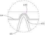
请一并参阅图13及图14,本发明的第八实施例提供的覆膜血管支架的结构与第七实施例的结构相似,不同之处在于:在第八实施例中,环状波形扩撑杆65的波峰651连接于覆膜20近端的环状定位杆64上。具体的,环状定位杆64及环状波形扩撑杆65均设置于覆膜的近端,所述环状定位杆64较所述环状波形扩撑杆65更邻近所述覆膜20的近端面,所述环状波形扩撑杆65低于环状编织网62的近端面,即所述环状波形扩撑杆65没有外露出所述环状编织网62的近端面625,且环状波形扩撑杆65较所述环状定位杆64更邻近远端。所述环状定位杆64与所述环状波形扩撑杆65的波峰651连接,在所述覆膜血管支架100展开的状态下,所述环状波形扩撑杆65的波峰651的径向支撑力扩撑所述环状定位杆64,所述环状定位杆64的径向支撑力与所述环状波形扩撑杆65的径向支撑力一并扩撑覆膜20的近端,使覆膜20与所述血管的内壁之间密封,防止内漏;且所述环状波形扩撑杆65的波谷653及波杆655均可以径向地扩撑覆膜20,使覆膜20密封贴合于血管的内壁。Please refer to FIG. 13 and FIG. 14 together. The structure of the stent-graft provided by the eighth embodiment of the present invention is similar to the structure of the seventh embodiment, the difference is that in the eighth embodiment, the annular waveform expands The
所述环状定位杆64上设置有与所述环状波形扩撑杆65的波峰651对应的连接弧杆645,所述连接弧杆645沿对应的波峰651弯曲延伸,每一波峰651连接于对应的连接弧杆645。具体的,所述环状定位杆64对应所述环状波形扩撑杆65的每一波峰651处朝近端弯曲,形成弧形的连接弧杆645,所述连接弧杆645沿对应的波峰651的弯曲而弯曲。所述环状波形扩撑杆65的波峰651与对应的连接弧杆645之间的医用缝线沿着每一波峰651的波形走向而伴随整个波峰651,且所述医用缝线缝合对应的覆膜20。The
请一并参阅图15及图16,本发明的第九实施例提供的覆膜血管支架的结构与第三实施例的结构相似,不同之处在于:在第九实施例中,环状定位架为至少一环状连接绳68,所述环状连接绳68固定于所述覆膜20的外表面或内表面。具体的,所述环状连接绳68固定于所述覆膜20的近端或远端的外表面或内表面。本实施例中,所述环状连接绳68固定于所述覆膜20的近端,具体的,所述环状连接绳68连接于所述环状波形扩撑杆65的波谷653与最近端的波形支撑杆42的波峰421之间。Please refer to FIG. 15 and FIG. 16 together, the structure of the stent-graft provided by the ninth embodiment of the present invention is similar to the structure of the third embodiment, the difference is: in the ninth embodiment, the annular spacer At least one looped connecting
所述环状连接绳68是由具有弹性的记忆合金制成的膨胀式的支撑圈,优选的,所述环状连接绳68是镍钛合金的支撑圈。所述环状连接绳68由一根记忆合金丝编织而成。The annular connecting
所述环状连接绳68可以通过缝合、热压或胶接等方式连接于所述覆膜20上,以使所述环状连接绳68与所述覆膜20能紧密固定,且所述环状连接绳68与所述环状波形扩撑杆65之间的连接,由环状连接绳68缠绕于环状波形扩撑杆65的波谷653完成。在所述覆膜血管支架100植入血管内后,所述环状定位杆64及所述环状波形扩撑杆65径向扩撑所述与环状连接绳68,以带动所述最近端的波形支撑杆42径向地一并扩撑覆膜20,使覆膜20与血管的内壁之间密封贴合,防止内漏;且所述主体支撑架40、环状连接绳68及所述环状波形扩撑杆65展开后均对所述血管的内壁有径向的扩撑力,能将覆膜血管支架稳定的定位于血管的内壁上,防止所述覆膜血管支架位移。The looped connecting
所述环状连接绳68绕环状波形扩撑杆65的每一波谷653至少缠绕一圈,本实施例中,所述环状连接绳68绕环状波形扩撑杆65的每一波谷653缠绕了两圈。The annular connecting
在其他实施例中,所述覆膜20的远端也可以一并设置有环状连接绳68及环状波形扩撑杆65,环状连接绳68缠绕于环状波形扩撑杆65的波峰651与最远端的波形支撑杆42的波谷之间,即所述环状波形扩撑杆65的波峰651贴接于所述覆膜20的远端,所述环状波形扩撑杆65除波峰651外,波杆655及波谷653均外露出所述覆膜20的远端面。所述环状连接绳68缠绕于所述环状波形扩撑杆65的波峰651与最远端的波形支撑杆42的波谷之间。In other embodiments, the distal end of the
在其它实施例中,所述环状连接绳68与所述环状波形扩撑杆65的波谷653/波峰651,以及环状连接绳68与波形支撑杆42的波峰/波谷的缠绕处可打结固定。In other embodiments, the looped connecting
在其他实施例中,所述环状连接绳68可以用含显影材料的显影丝取代,所述显影丝优选采用由含钽的镍钛合金金属丝。In other embodiments, the endless connecting
以上是本发明实施例的实施方式,应当指出,对于本技术领域的普通技术人员来说,在不脱离本发明实施例原理的前提下,还可以做出若干改进和润饰,这些改进和润饰也视为本发明的保护范围。The above are the implementations of the embodiments of the present invention. It should be pointed out that for those of ordinary skill in the art, without departing from the principles of the embodiments of the present invention, several improvements and modifications can also be made. These improvements and modifications are also It is regarded as the protection scope of the present invention.
Claims (16)
Translated fromChineseApplications Claiming Priority (2)
| Application Number | Priority Date | Filing Date | Title |
|---|---|---|---|
| CN201811653975 | 2018-12-29 | ||
| CN2018116539759 | 2018-12-29 |
Publications (2)
| Publication Number | Publication Date |
|---|---|
| CN111374810Atrue CN111374810A (en) | 2020-07-07 |
| CN111374810B CN111374810B (en) | 2025-03-07 |
Family
ID=70135337
Family Applications (2)
| Application Number | Title | Priority Date | Filing Date |
|---|---|---|---|
| CN201910255852.8AActiveCN111374810B (en) | 2018-12-29 | 2019-03-30 | A coated vascular stent with improved wall adhesion performance |
| CN201920425338.XUActiveCN210301319U (en) | 2018-12-29 | 2019-03-30 | A covered vascular stent with improved adherence properties |
Family Applications After (1)
| Application Number | Title | Priority Date | Filing Date |
|---|---|---|---|
| CN201920425338.XUActiveCN210301319U (en) | 2018-12-29 | 2019-03-30 | A covered vascular stent with improved adherence properties |
Country Status (1)
| Country | Link |
|---|---|
| CN (2) | CN111374810B (en) |
Cited By (3)
| Publication number | Priority date | Publication date | Assignee | Title |
|---|---|---|---|---|
| CN112386364A (en)* | 2020-11-10 | 2021-02-23 | 苏州中天医疗器械科技有限公司 | Hybrid braided stent |
| CN113749719A (en)* | 2021-05-31 | 2021-12-07 | 宁波迪创医疗科技有限公司 | Implanting instrument with fishbone-shaped anchoring structure and conveying system thereof |
| WO2023125387A1 (en)* | 2021-12-31 | 2023-07-06 | 先健科技(深圳)有限公司 | Covered stent |
Families Citing this family (6)
| Publication number | Priority date | Publication date | Assignee | Title |
|---|---|---|---|---|
| CN111374810B (en)* | 2018-12-29 | 2025-03-07 | 杭州唯强医疗科技有限公司 | A coated vascular stent with improved wall adhesion performance |
| CN112472381B (en)* | 2019-09-12 | 2023-06-16 | 先健科技(深圳)有限公司 | bracket |
| CN112472380B (en)* | 2019-09-12 | 2023-05-02 | 先健科技(深圳)有限公司 | Tectorial membrane support |
| CN113693777B (en)* | 2020-05-06 | 2025-09-12 | 杭州唯强医疗科技有限公司 | Vascular shunts and stents |
| CN114681121A (en)* | 2020-12-31 | 2022-07-01 | 深圳市先健畅通医疗有限公司 | stent graft |
| CN116370143B (en)* | 2023-03-30 | 2025-08-15 | 杭州唯强医疗科技有限公司 | Wall-attached vascular stent and tectorial stent system |
Citations (8)
| Publication number | Priority date | Publication date | Assignee | Title |
|---|---|---|---|---|
| CN2741534Y (en)* | 2004-10-12 | 2005-11-23 | 微创医疗器械(上海)有限公司 | Anti internal leakage film coated rack |
| US20060142836A1 (en)* | 2004-09-28 | 2006-06-29 | William A. Cook Australia Pty. Ltd. | Device for treating aortic dissection |
| US20080195191A1 (en)* | 2005-05-24 | 2008-08-14 | Qiyi Luo | Flexible Stent-Graft |
| US20140005764A1 (en)* | 2012-06-30 | 2014-01-02 | Cordis Corporation | Sealing mechanism for expandable vascular device |
| CN105769383A (en)* | 2016-03-18 | 2016-07-20 | 唯强医疗科技(上海)有限公司 | A kind of aortic bare stent and aortic dissection stent |
| CN106344209A (en)* | 2016-10-11 | 2017-01-25 | 有研医疗器械(北京)有限公司 | Abdominal aorta covered stent and conveying device thereof and using method |
| CN208229020U (en)* | 2017-08-01 | 2018-12-14 | 有研医疗器械(北京)有限公司 | A kind of branch type film-coated vascular bracket |
| CN210301319U (en)* | 2018-12-29 | 2020-04-14 | 杭州唯强医疗科技有限公司 | A covered vascular stent with improved adherence properties |
- 2019
- 2019-03-30CNCN201910255852.8Apatent/CN111374810B/enactiveActive
- 2019-03-30CNCN201920425338.XUpatent/CN210301319U/enactiveActive
Patent Citations (8)
| Publication number | Priority date | Publication date | Assignee | Title |
|---|---|---|---|---|
| US20060142836A1 (en)* | 2004-09-28 | 2006-06-29 | William A. Cook Australia Pty. Ltd. | Device for treating aortic dissection |
| CN2741534Y (en)* | 2004-10-12 | 2005-11-23 | 微创医疗器械(上海)有限公司 | Anti internal leakage film coated rack |
| US20080195191A1 (en)* | 2005-05-24 | 2008-08-14 | Qiyi Luo | Flexible Stent-Graft |
| US20140005764A1 (en)* | 2012-06-30 | 2014-01-02 | Cordis Corporation | Sealing mechanism for expandable vascular device |
| CN105769383A (en)* | 2016-03-18 | 2016-07-20 | 唯强医疗科技(上海)有限公司 | A kind of aortic bare stent and aortic dissection stent |
| CN106344209A (en)* | 2016-10-11 | 2017-01-25 | 有研医疗器械(北京)有限公司 | Abdominal aorta covered stent and conveying device thereof and using method |
| CN208229020U (en)* | 2017-08-01 | 2018-12-14 | 有研医疗器械(北京)有限公司 | A kind of branch type film-coated vascular bracket |
| CN210301319U (en)* | 2018-12-29 | 2020-04-14 | 杭州唯强医疗科技有限公司 | A covered vascular stent with improved adherence properties |
Cited By (4)
| Publication number | Priority date | Publication date | Assignee | Title |
|---|---|---|---|---|
| CN112386364A (en)* | 2020-11-10 | 2021-02-23 | 苏州中天医疗器械科技有限公司 | Hybrid braided stent |
| CN113749719A (en)* | 2021-05-31 | 2021-12-07 | 宁波迪创医疗科技有限公司 | Implanting instrument with fishbone-shaped anchoring structure and conveying system thereof |
| WO2022252878A1 (en)* | 2021-05-31 | 2022-12-08 | 宁波迪创医疗科技有限公司 | Implantation device having fishbone-shaped anchoring structures and delivery system therefor |
| WO2023125387A1 (en)* | 2021-12-31 | 2023-07-06 | 先健科技(深圳)有限公司 | Covered stent |
Also Published As
| Publication number | Publication date |
|---|---|
| CN111374810B (en) | 2025-03-07 |
| CN210301319U (en) | 2020-04-14 |
Similar Documents
| Publication | Publication Date | Title |
|---|---|---|
| CN210301319U (en) | A covered vascular stent with improved adherence properties | |
| JP5421929B2 (en) | Stent graft for reinforcing vascular abnormalities and methods related thereto | |
| JP5667544B2 (en) | Delivery system and method for automatically centering the proximal end of a stent graft | |
| JP4825665B2 (en) | Lumen device with enhanced mounting characteristics | |
| JP5350399B2 (en) | Stent / stent graft and related methods for reinforcing vascular abnormalities | |
| JP4783876B2 (en) | Stent graft, stent graft delivery (delivery) system and kit, and method for placing a stent graft | |
| US8663309B2 (en) | Asymmetric stent apparatus and method | |
| JP4282997B2 (en) | Upper renal prosthesis and renal artery bypass | |
| JP4081522B2 (en) | Temporary indwelling stent and stent graft | |
| JP4394125B2 (en) | Multi-lumen prosthesis system and method | |
| JP4476550B2 (en) | Prosthesis | |
| AU2018203557A1 (en) | Occluder and anastomosis devices | |
| CN209107690U (en) | Segmented overlay film frame | |
| CN111227991B (en) | Vascular stent and embedded branch stent | |
| BRPI0414109B1 (en) | stent graft, stent graft delivery system and kit and method for implanting stent graft | |
| US9398964B2 (en) | Device for securing a prosthesis to the internal wall of a body lumen | |
| CN118370625A (en) | Lumen stent and delivery system thereof | |
| CN111317595B (en) | A vascular stent for preventing the covering from slipping off | |
| CN209827101U (en) | Blood vessel stent and embedded branch stent thereof | |
| CN113116613A (en) | Covered stent | |
| CN110547896B (en) | Vascular tectorial membrane support | |
| WO2022022143A1 (en) | Membrane-covered stent | |
| WO2020108548A1 (en) | Developing mechanism for facilitating fixation and vascular stent thereof | |
| JP3878971B2 (en) | Temporary indwelling stent graft | |
| CN212592564U (en) | A film-carrying stent |
Legal Events
| Date | Code | Title | Description |
|---|---|---|---|
| PB01 | Publication | ||
| PB01 | Publication | ||
| SE01 | Entry into force of request for substantive examination | ||
| SE01 | Entry into force of request for substantive examination | ||
| GR01 | Patent grant | ||
| GR01 | Patent grant |