CN111374689A - CT scanning device and scanning frame thereof - Google Patents
CT scanning device and scanning frame thereofDownload PDFInfo
- Publication number
- CN111374689A CN111374689ACN201811610519.6ACN201811610519ACN111374689ACN 111374689 ACN111374689 ACN 111374689ACN 201811610519 ACN201811610519 ACN 201811610519ACN 111374689 ACN111374689 ACN 111374689A
- Authority
- CN
- China
- Prior art keywords
- window
- scanning
- housing
- engagement
- annular
- Prior art date
- Legal status (The legal status is an assumption and is not a legal conclusion. Google has not performed a legal analysis and makes no representation as to the accuracy of the status listed.)
- Granted
Links
Images


Classifications
- A—HUMAN NECESSITIES
- A61—MEDICAL OR VETERINARY SCIENCE; HYGIENE
- A61B—DIAGNOSIS; SURGERY; IDENTIFICATION
- A61B6/00—Apparatus or devices for radiation diagnosis; Apparatus or devices for radiation diagnosis combined with radiation therapy equipment
- A61B6/02—Arrangements for diagnosis sequentially in different planes; Stereoscopic radiation diagnosis
- A61B6/03—Computed tomography [CT]
- A61B6/032—Transmission computed tomography [CT]
- A61B6/035—Mechanical aspects of CT
- A—HUMAN NECESSITIES
- A61—MEDICAL OR VETERINARY SCIENCE; HYGIENE
- A61B—DIAGNOSIS; SURGERY; IDENTIFICATION
- A61B6/00—Apparatus or devices for radiation diagnosis; Apparatus or devices for radiation diagnosis combined with radiation therapy equipment
- A61B6/10—Safety means specially adapted therefor
- A61B6/102—Protection against mechanical damage, e.g. anti-collision devices
- A—HUMAN NECESSITIES
- A61—MEDICAL OR VETERINARY SCIENCE; HYGIENE
- A61B—DIAGNOSIS; SURGERY; IDENTIFICATION
- A61B6/00—Apparatus or devices for radiation diagnosis; Apparatus or devices for radiation diagnosis combined with radiation therapy equipment
- A61B6/44—Constructional features of apparatus for radiation diagnosis
- A61B6/4429—Constructional features of apparatus for radiation diagnosis related to the mounting of source units and detector units
Landscapes
- Health & Medical Sciences (AREA)
- Life Sciences & Earth Sciences (AREA)
- Engineering & Computer Science (AREA)
- Medical Informatics (AREA)
- Radiology & Medical Imaging (AREA)
- Molecular Biology (AREA)
- Biophysics (AREA)
- Nuclear Medicine, Radiotherapy & Molecular Imaging (AREA)
- Optics & Photonics (AREA)
- Pathology (AREA)
- Physics & Mathematics (AREA)
- Biomedical Technology (AREA)
- Heart & Thoracic Surgery (AREA)
- High Energy & Nuclear Physics (AREA)
- Surgery (AREA)
- Animal Behavior & Ethology (AREA)
- General Health & Medical Sciences (AREA)
- Public Health (AREA)
- Veterinary Medicine (AREA)
- Pulmonology (AREA)
- Theoretical Computer Science (AREA)
- Apparatus For Radiation Diagnosis (AREA)
Abstract
Translated fromChinese
Description
Translated fromChinese技术领域technical field
本文所述的实施例总体上涉及计算机断层(CT)成像设备,更具体地涉及用于CT扫描装置及其扫描架。Embodiments described herein relate generally to computed tomography (CT) imaging apparatus, and more particularly to apparatus for CT scanning and gantry thereof.
背景技术Background technique
扫描架(Gantry)是CT成像装置中非常重要的部分,其可保持X射线管及检测器。扫描装置具有供成像用X射线出入的环形扫描窗。在操作中,X射线源(X射线管)和检测器围绕待成像的对象旋转,或待成像物体旋转而X射线源和检测器静止。The gantry (Gantry) is a very important part of the CT imaging device, which can hold the X-ray tube and the detector. The scanning device has an annular scanning window through which X-rays for imaging enter and exit. In operation, the X-ray source (X-ray tube) and detector rotate around the object to be imaged, or the object to be imaged rotates while the X-ray source and detector are stationary.
医用电气设备国际标准IEC60601要求在评估设备安全性时,外壳的外部部件能经受250N的稳定测试力,这是为了模拟患者或操作员可以施加到扫描装置的力。对于CT扫描装置,扫描窗应尽可能薄,以衰减最少量的X射线,从而有助于系统能够对体积较大的患者进行成像。然而,随着扫描窗变薄,由所要求的250N测试力所带来的变形可能导致扫描窗与CT扫描装置内的旋转部件接触,从而对位于扫描装置腔内的患者或操作员造成潜在危害。The international standard for medical electrical equipment, IEC60601, requires that the outer parts of the enclosure can withstand a steady test force of 250N when evaluating the safety of the equipment, which is to simulate the force that a patient or operator can apply to the scanning device. For CT scanners, the scan window should be as thin as possible to attenuate the least amount of X-rays, helping the system to image larger patients. However, as the scan window becomes thinner, the deformation caused by the required 250N test force can cause the scan window to come into contact with rotating components within the CT scan unit, potentially causing harm to the patient or operator located within the scan unit cavity .
因此,需要一种新的用于锁定扫描窗的技术方案,其能够满足:1)在250N的推力下扫描窗不接触旋转部件;2)能够使用更薄的扫描窗材料;3)扫描装置壳体与扫描窗之间的液体密封。Therefore, there is a need for a new technical solution for locking the scanning window, which can satisfy: 1) the scanning window does not contact the rotating part under the thrust of 250N; 2) thinner scanning window material can be used; 3) the scanning device casing Fluid seal between body and scan window.
发明内容SUMMARY OF THE INVENTION
本发明的示例性实施例的目的正是在于提供这样一种CT扫描装置的扫描架,其能够通过硬性或半硬性接合来实现低变形的扫描窗啮合锁定结构,并且具有安全防护性。The purpose of the exemplary embodiments of the present invention is to provide such a scanning gantry of a CT scanning device, which can realize a low-deformation scanning window engaging and locking structure through rigid or semi-rigid engagement, and has safety protection.
具体地,本发明的示例性实施例提供了一种CT扫描装置的扫描架,包括:第一壳体,所述第一壳体具有第一腔膛;第二壳体,所述第二壳体与所述第一壳体相对地设置,所述第二壳体具有第二腔膛,其中在所述第一腔膛与所述第二腔膛之间存在间隙作为射线扫描腔膛;扫描窗组件,所述扫描窗组件包括具有内表面和外表面的环形窗主体,所述扫描窗组件与所述第一壳体和第二壳体啮合锁定且密封并覆盖所述射线扫描腔膛。以此方式,啮合锁定能够使得当外力被施加在所述扫描窗组件上时限制所述环形窗主体的变形,而密封能够防止所述第一壳体和第二壳体内的液体漏出并且防止扫描窗组件内侧的液体漏进所述第一壳体和第二壳体内。Specifically, an exemplary embodiment of the present invention provides a scanning gantry of a CT scanning device, including: a first casing, the first casing having a first cavity; a second casing, the second casing The body is arranged opposite to the first casing, the second casing has a second cavity, and a gap exists between the first cavity and the second cavity as a ray scanning cavity; scanning A window assembly includes an annular window body having an inner surface and an outer surface, the scan window assembly is engaged with the first housing and the second housing to lock and seal and cover the radiation scanning cavity. In this way, the engagement lock can limit the deformation of the annular window body when an external force is applied to the scanning window assembly, and the sealing can prevent the leakage of liquid in the first and second housings and prevent scanning Liquid inside the window assembly leaks into the first and second housings.
较佳地,所述扫描窗组件进一步包括:第一窗接合件与第二窗接合件,所述第一窗接合件与所述第二窗接合件分别设置在所述环形窗主体的外表面的两侧,所述第一窗接合件用于与所述第一壳体啮合并且所述第二窗接合件用于与所述第二壳体啮合。Preferably, the scanning window assembly further comprises: a first window engaging member and a second window engaging member, the first window engaging member and the second window engaging member are respectively disposed on the outer surface of the annular window body On both sides of the first window engaging member for engaging with the first housing and the second window engaging member for engaging with the second housing.
较佳地,所述第一窗接合件与所述第一壳体的啮合和所述第二窗接合件与所述第二壳体的啮合分别通过采用以下方式中的一种来实现:凸面/凹面啮合锁定、凸面/凹面旋转接触啮合锁定、紧密附着的表面啮合锁定、粘合剂啮合锁定、搭扣啮合锁定。Preferably, the engagement of the first window engagement member with the first housing and the engagement of the second window engagement member with the second housing are achieved by using one of the following methods: a convex surface /Female Mesh Lock, Male/Female Rotary Contact Mesh Lock, Adhesive Surface Mesh Lock, Adhesive Mesh Lock, Snap Mesh Lock.
较佳地,在采用凸面/凹面啮合锁定来实现的情况下,所述第一和/或第二窗接合件包括齿件,所述齿件在所述环形窗主体的轴向上具有一层或多层凸齿,所述第一和/或第二壳体在所述环形窗主体的轴向上包括一层或多层凹形的齿槽。优选地,啮合锁定的凸齿与齿槽的形状和尺寸是匹配的。Preferably, in the case of using male/female engaging locking, the first and/or second window engaging members comprise teeth having a layer in the axial direction of the annular window body or multiple layers of convex teeth, the first and/or second housings include one or more layers of concave teeth grooves in the axial direction of the annular window body. Preferably, the engaging and locking protruding teeth are matched in shape and size to the tooth slots.
较佳地,在采用凸面/凹面旋转接触啮合锁定来实现的情况下,所述第一窗接合件包括沿所述环形窗主体的周向分布的一个或多个扁平的齿件,所述第二窗接合件包括沿所述环形窗主体的周向分布的一个或多个凸块,所述第一壳体包括扁平的齿槽以用于啮合所述一个或多个扁平的齿件,所述第二壳体包括一个或多个倾斜或螺旋形的内齿槽以用于啮合所述一个或多个凸块。Preferably, in the case of using the convex/concave rotational contact engaging and locking to realize, the first window engaging member includes one or more flat teeth distributed along the circumferential direction of the annular window body, and the first window engaging member comprises one or more flat teeth The two-window engaging member includes one or more lugs distributed along the circumference of the annular window body, and the first housing includes a flat tooth slot for engaging the one or more flat teeth, so The second housing includes one or more inclined or helical internal tooth slots for engaging the one or more lugs.
较佳地,在采用紧密附着的表面啮合锁定来实现的情况下,所述第一和/或第二窗接合件是圆筒状或锥体状的,并且由半硬性材料构成,所述第一和/或第二壳体具有与之对应的圆筒形或锥体形硬质内表面。优选地,所述半硬性材料为半硬性橡胶材料。Preferably, the first and/or second window engaging elements are cylindrical or conical in shape, and constructed of The first and/or second shells have corresponding cylindrical or conical hard inner surfaces. Preferably, the semi-rigid material is a semi-rigid rubber material.
较佳地,在采用搭扣啮合锁定来实现的情况下,所述第一窗接合件和/或第二窗接合件以及对应的第一壳体和/或第二壳体分别为Velcro钩件和Velcro环件以构成一组搭扣啮合锁定。Preferably, in the case of using hasp engagement and locking, the first and/or second window engaging pieces and the corresponding first and/or second housings are Velcro hooks, respectively. and Velcro rings to form a set of snaps to engage and lock.
较佳地,在采用所述粘合剂啮合锁定来实现的情况下,所述第一窗接合件和/或第二窗接合件以及对应的第一壳体和/或第二壳体的啮合锁定使用可多次拆装的粘接剂来构成啮合锁定。Preferably, the engagement of the first and/or second window engagement members and the corresponding first and/or second housings, where the adhesive engagement locking is employed The lock uses a multi-removable adhesive to form an engaging lock.
较佳地,所述第一窗接合件和/或所述第二窗接合件沿所述环形窗主体的环周方向是连续的。Preferably, the first window joint member and/or the second window joint member is continuous along the circumferential direction of the annular window body.
较佳地,所述第一窗接合件和/或所述第二窗接合件沿所述环形窗主体的环周方向具有多个离散的子接合件。Preferably, the first window joint and/or the second window joint has a plurality of discrete sub joints along the circumferential direction of the annular window body.
较佳地,所述第一窗接合件和/或所述第二窗接合件环绕所述环形窗主体的整个环周,或者所述第一窗接合件和/或所述第二窗接合件环绕所述环形窗主体的部分环周。Preferably, the first window joint and/or the second window joint surrounds the entire circumference of the annular window body, or the first window joint and/or the second window joint surrounding a portion of the circumference of the annular window body.
较佳地,所述扫描窗组件还包括:弹性带,所述弹性带沿所述环形窗主体的边缘设置在所述环形窗主体的内表面的两侧,以提供压力将所述扫描窗组件在整周沿其外径方向朝向所述第一壳体和所述第二壳体按压。Preferably, the scanning window assembly further comprises: elastic bands arranged on both sides of the inner surface of the annular window body along the edge of the annular window body to provide pressure to hold the scanning window assembly together. It presses toward the said 1st case and the said 2nd case along the outer diameter direction of the whole circumference.
较佳地,所述扫描窗组件还包括:弹性软密封材料,所述弹性软密封材料沿所述环形窗主体的边缘设置在所述环形窗主体的外表面的两侧,所述弹性软密封材料在扫描窗组件的弹性压力作用下被压缩变形以实现第一壳体与扫描窗组件和第二壳体与扫描窗组件的密封。以此方式,可以防止第一壳体和第二壳体内的液体漏出,并且防止扫描窗组件内侧的液体漏进第一壳体和第二壳体内。Preferably, the scanning window assembly further comprises: elastic soft sealing material, the elastic soft sealing material is arranged on both sides of the outer surface of the annular window main body along the edge of the annular window main body, the elastic soft sealing material is The material is compressed and deformed under the action of the elastic pressure of the scanning window assembly to achieve the sealing between the first casing and the scanning window assembly and the second casing and the scanning window assembly. In this way, it is possible to prevent the liquid inside the first and second housings from leaking out and the liquid inside the scanning window assembly from leaking into the first and second housings.
较佳地,所述第一壳体进一步包括:第一壳体接合件,所述第一壳体接合件设置在所述第一腔膛靠近所述射线扫描腔膛的内侧,用于与所述扫描窗组件啮合锁定;所述第二壳体进一步包括:第二壳体接合件,所述第二壳体接合件设置在所述第二腔膛靠近所述射线扫描腔膛的内侧,用于与所述扫描窗组件啮合锁定。作为一示例,所述第一壳体接合件和/或所述第二壳体接合件沿所述环形窗主体的环周方向是连续的。作为另一示例,所述第一壳体接合件和/或所述第二壳体接合件沿所述环形窗主体的环周方向具有多个离散的子接合件。Preferably, the first casing further comprises: a first casing engaging member, the first casing engaging member is arranged on the inner side of the first cavity close to the ray scanning cavity, and is used for connecting with the ray scanning cavity. The scanning window assembly is engaged and locked; the second casing further comprises: a second casing engaging member, the second casing engaging member is arranged on the inner side of the second cavity close to the ray scanning cavity, and is used for to engage and lock with the scan window assembly. As an example, the first housing engaging member and/or the second housing engaging member are continuous along the circumferential direction of the annular window body. As another example, the first housing engaging member and/or the second housing engaging member has a plurality of discrete sub-engaging members along the circumferential direction of the annular window body.
较佳地,所述第一壳体还包括:第一密封区,所述第一密封区位于所述第一腔膛内,用于与对应的扫描窗组件的第一弹性软密封材料形成密封;所述第二壳体还包括:第二密封区,所述第二密封区位于所述第二腔膛内,用于与对应的扫描窗组件的第二弹性软密封材料形成密封。Preferably, the first housing further comprises: a first sealing area, the first sealing area is located in the first cavity, and is used to form a seal with the first elastic soft sealing material of the corresponding scanning window assembly ; the second housing further comprises: a second sealing area, the second sealing area is located in the second cavity, and is used for forming a seal with the second elastic soft sealing material of the corresponding scanning window assembly.
较佳地,所述第一壳体接合件和/或所述第二壳体接合件环绕所述环形窗主体的整个环周,或者所述第一壳体接合件和/或所述第二壳体接合件环绕所述环形窗主体的部分环周。Preferably, the first housing engaging member and/or the second housing engaging member surrounds the entire circumference of the annular window body, or the first housing engaging member and/or the second housing engaging member A housing engagement member surrounds a portion of the circumference of the annular window body.
较佳地,所述环形窗主体由低X射线衰减的薄层材料制成。优选地,所述低X射线衰减的薄层材料包括聚碳酸酯。Preferably, the annular window body is made of a low X-ray attenuation thin layer material. Preferably, the low X-ray attenuation sheet material comprises polycarbonate.
较佳地,所述环形窗主体自身可具齿件功能以直接与所述第一壳体和第二壳体紧密附着啮合锁定。Preferably, the annular window body itself can have a tooth function to directly engage and lock with the first housing and the second housing.
根据本发明的另一示例性实施例,提供了一种CT扫描装置,包括:如上所述的扫描架;以及设置在所述扫描架上的X射线源与检测器组件。According to another exemplary embodiment of the present invention, there is provided a CT scanning apparatus, comprising: the scanning gantry as described above; and an X-ray source and detector assembly disposed on the scanning gantry.
在根据上述示例性实施例的扫描架和CT扫描装置中,该扫描窗组件,当它被放在所述第一壳体的第一腔膛内和所述第二壳体的第二腔膛内,与所述第一壳体和第二壳体啮合锁定和密封时,该扫描窗组件具有的恢复原形状的回弹性力,将所述扫描窗组件朝向所述第一壳体和所述第二壳体按压,以达到紧密啮合锁定和密封。In the scanning gantry and the CT scanning apparatus according to the above-described exemplary embodiments, the scanning window assembly, when it is placed in the first cavity of the first housing and the second cavity of the second housing Inside, when engaging with the first housing and the second housing to lock and seal, the scanning window assembly has a resilient force that restores its original shape to move the scanning window assembly toward the first housing and the The second housing is pressed to achieve tight engagement locking and sealing.
此外,该扫描窗组件具有一定的易变形性以易于该扫描窗的安装和拆卸,并且当无外力或扫描窗组件从扫描装置拆卸下时,扫描装置上和扫描窗组件上的所有部件在回弹力作用下能恢复到原来的形状。In addition, the scanning window assembly has a certain deformability to facilitate the installation and removal of the scanning window, and when there is no external force or the scanning window assembly is detached from the scanning device, all the parts on the scanning device and the scanning window assembly return to the back. It can return to its original shape under the action of elasticity.
而且,该扫描窗组件具有安全防护性,且具有一定的易变形性和当无外力时具有恢复原形状的回弹性,第一窗接合件、第二窗接合件、弹性软密封材料和弹性带都固定在环形窗主体上。Moreover, the scanning window assembly has safety protection, and has certain easy deformation and resilience to restore the original shape when there is no external force. The first window joint, the second window joint, the elastic soft sealing material and the elastic band are fixed on the main body of the annular window.
进一步地,当来自患者或操作者的力可能施加于扫描窗组件时,扫描窗组件的受力区域想要向外径方向移动,受力区域附近想要倾斜,但扫描窗组件与第一壳体和第二壳体之间的硬性或半硬性啮合锁定,即,具有足够刚度的啮合锁定会阻挡环形窗主体的移动和倾斜,由此,环形窗主体的变形显著减小了。这里所述的硬性啮合锁定表示在压力的作用下啮合锁定物之间的变形比较小或没有。这里所述的半硬性啮合锁定表示在压力的作用下啮合锁定物之间有一些变形但是不大。这里所述的弹性软密封表示在压力作用下弹性软密封材料有大的变形。Further, when the force from the patient or the operator may be applied to the scanning window assembly, the force-bearing area of the scanning window assembly wants to move in the outer radial direction, and the vicinity of the force-bearing area wants to be inclined, but the scanning window assembly is connected to the first housing. A rigid or semi-rigid engagement lock between the body and the second housing, ie an engagement lock with sufficient rigidity, blocks movement and tilting of the annular window body, whereby deformation of the annular window body is significantly reduced. Hard engagement locks as described herein mean little or no deformation between the engagement locks under pressure. The semi-rigid engagement lock described here means that there is some deformation between the engagement locks under pressure but not much. The elastic soft seal described here means that the elastic soft sealing material has a large deformation under the action of pressure.
附图说明Description of drawings
通过结合附图对于本发明的示例性实施例进行描述,可以更好地理解本发明,在附图中:The present invention may be better understood by describing exemplary embodiments of the present invention in conjunction with the accompanying drawings, in which:
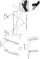
图1示出了根据本发明示例性实施例的CT扫描装置的扫描架10的示意图;FIG. 1 shows a schematic diagram of a
图2示出了传统CT扫描装置中扫描窗的变形示意图;Fig. 2 shows the deformation schematic diagram of the scanning window in the conventional CT scanning device;
图3示出了根据本发明的第一实施例的用于CT扫描装置的扫描架10的扫描窗组件30的示意图;FIG. 3 shows a schematic diagram of the
图4示出了根据本发明的第一实施例的CT扫描装置的扫描架10的第一壳体12和第二壳体14的示意图;4 shows a schematic diagram of the
图5示出了根据本发明第一实施例的图3所示的扫描窗组件30与图4所示的第一壳体12和第二壳体14之间的啮合锁定密封结构的示意图;FIG. 5 shows a schematic diagram of the engagement locking sealing structure between the
图6示出了根据本发明的第二实施例的扫描窗组件30与第一壳体12和第二壳体14之间的啮合锁定密封结构的示意图;FIG. 6 shows a schematic diagram of the engagement locking sealing structure between the
图7示出了根据本发明的第三实施例的扫描窗组件30与第一壳体12和第二壳体14之间的啮合锁定密封结构的示意图;FIG. 7 shows a schematic diagram of the engagement locking sealing structure between the
图8示出了根据本发明的第四实施例的扫描窗组件30与第一壳体12和第二壳体14之间的啮合锁定密封结构的示意图;FIG. 8 shows a schematic diagram of the engagement locking sealing structure between the
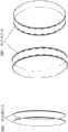
图9和图10示出了根据本发明的第五实施例的扫描窗组件30与第一壳体12和第二壳体14之间的啮合锁定密封结构的示意图;FIG. 9 and FIG. 10 are schematic diagrams illustrating the engagement locking and sealing structure between the
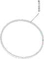
图11示出了根据本发明实施例的啮合锁定密封结构中的360°的齿件分布;FIG. 11 shows a 360° distribution of teeth in a meshing and locking sealing structure according to an embodiment of the present invention;
图12示出了根据本发明实施例的啮合锁定密封结构中的部分区域的齿件分布;FIG. 12 shows the distribution of teeth in a partial area of the meshing and locking sealing structure according to an embodiment of the present invention;
图13示出了根据本发明实施例的啮合锁定密封结构中的连续的齿槽分布;以及Figure 13 shows a continuous distribution of cogging in a mesh lock seal structure according to an embodiment of the present invention; and
图14示出了根据本发明实施例的啮合锁定密封结构中的离散的齿槽分布。14 illustrates a discrete cogging distribution in a mesh lock seal structure according to an embodiment of the present invention.
具体实施方式Detailed ways
以下将描述本发明的具体实施方式,需要指出的是,在这些实施方式的具体描述过程中,为了进行简明扼要的描述,本说明书不可能对实际的实施方式的所有特征均作详尽的描述。应当可以理解的是,在任意一种实施方式的实际实施过程中,正如在任意一个工程项目或者设计项目的过程中,为了实现开发者的具体目标,为了满足系统相关的或者商业相关的限制,常常会做出各种各样的具体决策,而这也会从一种实施方式到另一种实施方式之间发生改变。此外,还可以理解的是,虽然这种开发过程中所作出的努力可能是复杂并且冗长的,然而对于与本发明公开的内容相关的本领域的普通技术人员而言,在本公开揭露的技术内容的基础上进行的一些设计,制造或者生产等变更只是常规的技术手段,不应当理解为本公开的内容不充分。The specific embodiments of the present invention will be described below. It should be noted that, in the specific description of these embodiments, for the sake of brevity and conciseness, this specification may not describe all the features of the actual embodiments in detail. It should be understood that, in the actual implementation process of any embodiment, just as in the process of any engineering project or design project, in order to achieve the developer's specific goals, in order to meet the system-related or business-related constraints, Often a variety of specific decisions are made, which also vary from one implementation to another. Furthermore, it will also be appreciated that while such development efforts may be complex and tedious, for those of ordinary skill in the art to which this disclosure pertains, the techniques disclosed in this disclosure will Some changes in design, manufacture or production based on the content are only conventional technical means, and it should not be understood that the content of the present disclosure is insufficient.
除非另作定义,权利要求书和说明书中使用的技术术语或者科学术语应当为本发明所属技术领域内具有一般技能的人士所理解的通常意义。本发明专利申请说明书以及权利要求书中使用的“第一”、“第二”以及类似的词语并不表示任何顺序、数量或者重要性,而只是用来区分不同的组成部分。“一个”或者“一”等类似词语并不表示数量限制,而是表示存在至少一个。“包括”或者“包含”等类似的词语意指出现在“包括”或者“包含”前面的元件或者物件涵盖出现在“包括”或者“包含”后面列举的元件或者物件及其等同元件,并不排除其他元件或者物件。“连接”或者“相连”等类似的词语并非限定于物理的或者机械的连接,也不限于是直接的还是间接的连接。Unless otherwise defined, technical or scientific terms used in the claims and the specification shall have the ordinary meaning as understood by those with ordinary skill in the technical field to which this invention belongs. The terms "first", "second" and similar terms used in the description of the patent application and the claims of the present invention do not denote any order, quantity or importance, but are only used to distinguish different components. "A" or "an" and the like do not denote a quantitative limitation, but rather denote the presence of at least one. Words like "including" or "comprising" mean that the elements or items appearing before "including" or "including" cover the elements or items listed after "including" or "including" and their equivalents, and do not exclude other components or objects. Words like "connected" or "connected" are not limited to physical or mechanical connections, nor are they limited to direct or indirect connections.
图1示出根据本发明实施例的CT扫描装置的扫描架10的示意图。参照图1,CT扫描装置包括扫描架10,该扫描架10包括第一壳体12、第二壳体14、上盖16、侧盖18、底盖20、扫描窗组件30。扫描架10上可以相对地设置有X射线源与检测器组件(未示出)。在操作中,X射线源将X射线束透过扫描窗组件30和患者(未示出)投射到扫描装置的扫描架10的相对侧的检测器(例如,检测器阵列),检测器组件收集衰减的X射线束数据。扫描架10的第一壳体12、第二壳体14、上盖16、侧盖18和底盖20可以各自独立安装和拆卸,也可以是部分或全部一体形成的。例如,第一壳体12与侧盖18可以是一体式形成的单个构件,或者第二壳体14、侧盖18与底盖20可以是一体式形成的单个构件,等等。特别地,在一些实施例中,扫描架10的壳部可以仅由第一壳体12和第二壳体14构成。FIG. 1 shows a schematic diagram of a
第一壳体12和第二壳体14可以分别包括贯穿其的第一腔膛122和第二腔膛142。在第一壳体12的第一腔膛122与第二壳体14的第二腔膛142之间存在一间隙,即射线扫描腔膛。可使X射线束穿过该间隙和患者以进行CT扫描。扫描窗组件30覆盖该间隙,由此可防止扫描装置内液体泄漏出扫描装置的扫描架10或外部的液体渗入扫描装置的扫描架10内,同时当患者或操作员在扫描窗组件30上施加力时他们不接触旋转部件以确保安全,而且这样一来使整个结构具有较小的X射线衰减,并且易于组装和拆卸。The
如图2所示,在传统的CT扫描装置中,当在扫描窗组件的窗口层上施加力时,扫描窗组件的窗口层会发生比较大的变形。产生该变形的因素上可以归因于五个因素:泡沫变形、弹性带倾斜、窗口层移动、窗口层伸长、第一壳体的第一腔膛靠近射线扫描腔膛侧和第二壳体的第二腔膛靠近射线扫描腔膛侧的变形。其中前三个因素是主要的。在经受250N测试时,传统CT扫描装置的扫描窗的变形较大。As shown in FIG. 2 , in a conventional CT scanning device, when a force is applied to the window layer of the scanning window assembly, the window layer of the scanning window assembly will undergo relatively large deformation. The causes of this deformation can be attributed to five factors: foam deformation, inclination of the elastic band, movement of the window layer, elongation of the window layer, the first cavity of the first shell being close to the side of the ray scanning cavity and the second shell The deformation of the second cavity close to the ray scanning cavity side. The first three factors are the main ones. When subjected to the 250N test, the deformation of the scanning window of the conventional CT scanning device is relatively large.
第一实施例first embodiment
图3示出根据本发明的第一实施例的用于扫描架10的扫描窗组件30的示意图,其示例性地示出了扫描窗组件30的第一窗接合件308和第二窗接合件310。图4示出根据本发明的第一实施例的扫描架10的第一壳体12和第二壳体14的示意图,其示例性地示出了第一壳体12上的第一壳体接合件408和第二壳体14上的第二壳体接合件410。3 shows a schematic diagram of the
参照图3,扫描窗组件30可以包括具有内表面和外表面的环形窗主体302(例如,环形的薄层)、弹性带304、弹性软密封材料306、第一窗接合件308和第二窗接合件310。扫描窗组件30可以是可拆卸的部件。在组装扫描装置的扫描架10时,扫描窗组件30被置于第一壳体12的第一腔膛122与第二壳体14的第二腔膛142内,以与第一壳体12和第二壳体14啮合并且覆盖第一腔膛122与第二腔膛142之间的间隙,即射线扫描腔膛。这样的啮合使得当外力被施加在扫描窗组件30上时可以限制环形窗主体302的变形,同时被压缩的弹性软密封材料防止了扫描装置内外液体的泄漏。3, the
环形窗主体302可以由低X射线衰减的薄层材料制成,具有安全防护性,且具有易变形性和当无外力时具有恢复原形状的回弹性。下文中描述的第一窗接合件、第二窗接合件、弹性软密封材料和弹性带都固定或粘接在环形窗主体上。在本发明的示例性实施例中,环形窗主体302可以由聚碳酸酯或其它具有弹性的低X射线衰减的薄层材料构成。The
弹性带304沿环形窗主体302的边缘设置在环形窗主体302的内表面的两侧,提供弹性压力在第一腔膛122和第二腔膛142内整周将扫描窗组件30朝向第一壳体和第二壳体按压。在本发明的示例性实施例中,弹性带304可以由不锈钢或其他弹性材料构成。
弹性软密封材料306可以沿环形窗主体302的边缘设置在环形窗主体302的外表面的两侧,当弹性带在第一腔膛122和第二腔膛142内整周将扫描窗组件30朝向第一壳体和第二壳体按压时,在环形窗主体与第一壳体上的第一弹性密封区之间和第二壳体上的第二弹性密封区之间的弹性软密封材料被压缩,它们之间达到密封状态,以防止经过所述第一壳体12与环形窗主体302之间和第二壳体14与环形窗主体302之间的液体泄漏。弹性软密封材料306可以具有大的易变形性并且在无外力时在弹力作用下恢复原形状。在本发明的示例性实施例中,弹性软密封材料306可以是比较软的弹性材料,例如泡沫橡胶。The elastic
参照图4,第一壳体接合件408可以被固定在第一壳体12的腔膛122内或者可以是第一壳体12的一部分,第二壳体接合件410可以被固定在第二壳体14的腔膛142内或者可以是第二壳体14的一部分。4, the first
第一窗接合件308以及第二窗接合件310分别设置在环形窗主体302的外表面的两侧,该第一窗接合件308用于与第一壳体12的第一壳体接合件408啮合,并且该第二窗接合件310用于与第二壳体14的第二壳体接合件410啮合。第一窗接合件308与第一壳体接合件408的啮合以及第二窗接合件310与第二壳体接合件410的啮合分别通过采用以下方式中的一种来实现:凸面/凹面啮合锁定,搭扣啮合锁定(Velcro啮合锁定),凸面/凹面旋转接触啮合锁定,紧密附着的表面啮合锁定、粘合剂啮合锁定。The first
在当前实施例中,采用凸面/凹面接合来实现第一窗接合件308与第一壳体接合件408的啮合以及第二窗接合件310与第二壳体接合件410的啮合。具体地,第一窗接合件308和/或第二窗接合件310包括沿环形窗主体302的周向分布的一个或多个齿件(即,凸面),所述一个或多个齿件在环形窗主体302的轴向上具有一层或多层凸齿,所述第一壳体接合件408和/或第二壳体接合件410在环形窗主体302的轴向上包括一层或多层环形凹槽(即,凹面)的齿槽。In the current embodiment, a male/female engagement is employed to achieve the engagement of the first
结合附图11可知,可选地,多个齿件可环绕环形窗主体302的整个环周(即360°)分布,并且第一壳体接合件408和第二壳体接合件410上的齿槽也是360°环形的。或者,如图12所示,多个齿件可环绕环形窗主体302的环周的多个局部而非整个环周,并且相应地仅在第一壳体接合件408和第二壳体接合件410的部分区域上存在齿槽。11 , optionally, a plurality of teeth may be distributed around the entire circumference (ie, 360°) of the
另外,可选地,如图13所示,齿槽绕着环形窗主体302的环周可以是连续分布的。或者,如图14所示,齿槽绕着环形窗主体302的环周可以以一定间隔离散地分布。Additionally, alternatively, as shown in FIG. 13 , the gullets may be continuously distributed around the circumference of the
此外,齿件可以是环形窗主体302表面上的凸面体。例如,齿件可以是沿着环形窗主体302的外表面旋转分布的凸部所形成的实体,或者可以是扫掠环形窗主体302的外表面的凸部所形成的实体。齿槽可以是表面上的凹陷。例如,齿槽可以是沿着壳体的腔膛的内表面旋转分布的凹部所形成的凹槽,或者可以是扫掠壳体的腔膛的内表面的凹部所形成的凹槽。齿件与齿槽之间的形状和尺寸相匹配。当齿件与齿槽啮合时,可以阻止沿环形窗主体302的外径方向和轴向上的齿件与齿槽之间的相对移动和倾斜。Additionally, the teeth may be convex bodies on the surface of the
在一些实施例中,可以在扫描窗组件30上提供离散或连续的齿件。当连续的齿件可以确保扫描窗组件30具有足够的可恢复变形性以易于它的组装和拆卸时,可以使用连续的齿件。当连续的齿件无法确保扫描窗组件30具有足够的可恢复变形性以易于组装和拆卸时,可以使用离散的齿件。例如,扫描窗组件30可以具有离散的硬质齿件,或者可以具有连续的半硬质橡胶齿件。当然,扫描窗组件30也可以具有离散的半硬质齿件,例如离散的橡胶齿件。In some embodiments, discrete or continuous teeth may be provided on
回到图3,在第一实施例中,第一窗接合件308以及第二窗接合件310分别被示为以一定间隔分布的多个齿件(即,凸面),并且所述多个齿件中的每一个在环形窗主体302的轴向上具有两层凸齿。如图4所示,第一壳体接合件408和第二壳体接合件410各自在环形窗主体302的轴向上包括两个齿槽,分别用于与第一窗接合件308和第二窗接合件310上的对应的两层凸齿齿件相互啮合锁定。Returning to FIG. 3, in the first embodiment, the first
图5示出了根据第一实施例的图3所示的扫描窗组件30与图4所示的第一壳体12和第二壳体14之间的啮合锁定密封结构的示意图。环形窗主体302的外表面两侧上的第一窗接合件308和第二窗接合件310可以相对地啮合在第一壳体接合件408和第二壳体接合件410中,通过将每一个窗接合件(例如,图3中的齿件)与相应的壳体接合件(即,图4中的齿槽)相啮合锁定来固定扫描窗组件30,从而实现扫描窗组件30与第一壳体12和第二壳体14之间的硬性或半硬性啮合。由此,即使使用较薄的环形窗主体(例如,环形的薄层),当被施加力时,其变形也很小。以此方式,扫描窗组件30可以同时实现液体的密封性、针对外力的安全防护性、较小的X射线衰减以及易于组装和拆卸的便利性。FIG. 5 shows a schematic diagram of the engagement locking sealing structure between the scanning
第二实施例Second Embodiment
图6示出了根据本发明的第二实施例的扫描窗组件30与第一壳体12和第二壳体14之间的啮合锁定密封结构的示意图。根据第二实施例的啮合锁定密封结构的大部分细节与根据第一实施例的啮合锁定密封结构是相同的,在此不再赘述。以下主要描述第二实施例与第一实施例的不同之处。FIG. 6 shows a schematic diagram of the engagement locking sealing structure between the scanning
参照图6,不同于第一实施例中所采用的凸面/凹面接合,根据第二实施例的啮合锁定密封结构采用搭扣啮合锁定(Velcro啮合锁定)(即,魔术贴)来实现第一窗接合件308与第一壳体接合件408的啮合以及第二窗接合件310与第二壳体接合件410的啮合锁定。Referring to FIG. 6 , unlike the convex/concave joint employed in the first embodiment, the mesh lock sealing structure according to the second embodiment employs a snap mesh lock (Velcro mesh lock) (ie, Velcro) to realize the first window The engagement of the
具体地,第一窗接合件308和/或第二窗接合件310以及对应的第一壳体接合件408和/或第二壳体接合件410分别为Velcro钩件(Hook)和Velcro环件(Loop)以构成一组Velcro紧固件,由此实现扫描窗组件30与第一壳体12和第二壳体14之间的啮合锁定。Specifically, the first
第三实施例Third Embodiment
图7示出了根据本发明的第三实施例的扫描窗组件30与第一壳体12和第二壳体14之间的啮合锁定密封结构的示意图。根据第三实施例的啮合锁定密封结构的大部分细节与根据第一实施例的啮合锁定密封结构是相同的,在此不再赘述。以下主要描述第三实施例与第一实施例的不同之处。FIG. 7 shows a schematic diagram of the engagement locking sealing structure between the scanning
参照图7,与第一实施例中的两层凸齿齿件与两层齿槽的组合不同,在第三实施例中,扫描窗组件30上的多个齿件在环形窗主体302的外表面的两侧分别为单层凸齿齿件。即,第一窗接合件308和/或第二窗接合件310包括一个或多个齿件(即,凸面),所述一个或多个齿件在环形窗主体302的轴向上具有单层凸齿,所述第一和/或第二壳体接合件408、410在环形窗主体302的轴向上包括一层凹形的齿槽。Referring to FIG. 7 , different from the combination of two layers of protruding teeth and two layers of teeth in the first embodiment, in the third embodiment, the plurality of teeth on the
第四实施例Fourth Embodiment
图8示出了根据本发明的第四实施例的扫描窗组件30与第一壳体12和第二壳体14之间的啮合锁定密封结构的示意图。根据第四实施例的啮合锁定密封结构的大部分细节与根据第一实施例的啮合锁定密封结构是相同的,在此不再赘述。以下主要描述第四实施例与第一实施例的不同之处。FIG. 8 shows a schematic diagram of the engagement locking sealing structure between the scanning
参照图8,与第一实施例中的两层凸齿齿件与两层凹槽齿槽的组合不同,在第四实施例中,第一窗接合件308包括沿环形窗主体302的周向分布的一个或多个扁平的齿件,而第二窗接合件310包括沿环形窗主体302的周向分布的一个或多个凸块。第一壳体接合件408包括扁平的齿槽以用于啮合所述一个或多个扁平的齿件,而第一壳体接合件410包括一个或多个倾斜或螺旋形的内齿以用于啮合所述一个或多个凸块,从而实现扫描窗组件30与第一壳体12和第二壳体14之间的啮合锁定。Referring to FIG. 8 , in the fourth embodiment, the first
此外,具有扁平的齿槽的第一壳体接合件408能够使具有扁平的齿件的扫描窗组件30沿环形窗主体302的周向自由旋转,而没有轴向的移动,从而使得扫描窗组件30可以旋转,直到扫描窗组件30上的凸块接触至第二壳体接合件的倾斜或螺旋形的内齿的表面。In addition, the first
第五实施例Fifth Embodiment
图9和图10示出了根据本发明的第五实施例的扫描窗组件30与第一壳体12和第二壳体14之间的啮合锁定密封结构的示意图。根据第五实施例的啮合锁定密封结构的大部分细节与根据第一实施例的啮合锁定密封结构是相同的,在此不再赘述。以下主要描述第五实施例与第一实施例的不同之处。FIGS. 9 and 10 are schematic diagrams illustrating the engagement and locking sealing structure between the scanning
不同于第一实施例中所采用的凸面/凹面接合,第五实施例中采用紧密附着的表面啮合来实现第一窗接合件308与第一壳体接合件408的啮合以及第二窗接合件310与第二壳体接合件410的啮合。当采用紧密附着的表面啮合时,第一窗接合件和/或第二窗接合件是连续圆筒状或连续锥体状的并且由半硬性材料构成,而且第一壳体接合件和/或第二壳体接合件具有圆筒形或锥体形硬质内表面以与圆筒状或锥体状的第一窗接合件和/或第二窗接合件相匹配。半硬性材料可以是指具有一定的变形性和当无外力时具有恢复原形状的回弹性的材料,以确保扫描窗组件30具有足够的可恢复变形性以易于它的组装和拆卸。Unlike the convex/concave engagement employed in the first embodiment, the fifth embodiment employs a close-adhering surface engagement to achieve engagement of the first
理论上,可以将紧密附着的表面啮合看作是凸面/凹面啮合当凹面/凸面的凹度/凸度接近零时的特例,此时啮合变成圆筒或锥体啮合。当力被施加在扫描窗组件30上时,半硬性圆筒或锥体啮合可以限制环形窗主体302的变形。In theory, closely attached surface meshes can be viewed as a special case of convex/concave meshes when the concavity/convexity of the concave/convex surface approaches zero, and the mesh becomes a cylindrical or cone mesh. The semi-rigid cylinder or cone engagement may limit deformation of the
具体参照图9,第一窗接合件308和第二窗接合件310是连续的半硬质圆筒,并且第一壳体接合件408和第二壳体接合件410具有圆筒形硬质内表面以用于分别啮合锁定连续的半硬质圆筒状第一窗接合件308和第二窗接合件310,从而实现扫描窗组件30与第一壳体12和第二壳体14之间的半硬性啮合锁定。9, the first window joint 308 and the second window joint 310 are continuous semi-rigid cylinders, and the first shell joint 408 and the second shell joint 410 have a cylindrical hard inner Surfaces for engaging and locking the continuous semi-rigid cylindrical first
再参照图10,第一窗接合件308和第二窗接合件310是连续的半硬质锥体,并且第一壳体接合件408和第二壳体接合件410具有锥体形硬质内表面以用于接合连续的半硬质锥体状的第一窗接合件308和第二窗接合件310,从而实现扫描窗组件30与第一壳体12和第二壳体14之间的半硬性的啮合锁定。Referring again to FIG. 10 , the first
在上述两种情况(圆筒啮合锁定或锥体啮合锁定)下,采用硬度合适(即,半硬性)的材料来形成扫描窗组件30上的圆筒状或锥体状第一窗接合件308和第二窗接合件310。同时,扫描窗组件30上的圆筒状或锥体状第一窗接合件308与第一壳体接合件408材料之间和第二窗接合件310与第二壳体接合件410材料之间要有足够高的摩擦系数和摩擦力以阻止它们之间的相对滑动。具体地,可比如使用橡胶材料,作为圆筒状或锥体状第一窗接合件308和第二窗接合件310具有合适硬度的材料之一,由于啮合锁定件之间存在高摩擦系数,在弹性带304的弹力按压下有较大的摩擦力,可以阻止扫描窗组件30与扫描架的第一壳体12和第二壳体14之间发生相对移动。当然,也可使用其它任何硬度和摩擦系数合适的材料,只要其能够阻止扫描窗组件30与扫描架的第一壳体12和第二壳体14之间发生相对移动就可以。In both cases described above (cylindrical engagement lock or cone engagement lock), the cylindrical or conical first
例如,扫描窗组件30的第一窗接合件308和/或第二窗接合件310可以由沿环形扫描窗主体302离散分布的圆筒状或锥体状的半硬性材料构成。For example, the first
第六实施例Sixth Embodiment
图6示出了根据本发明的第二实施例的扫描窗组件30与第一壳体12和第二壳体14之间的啮合锁定密封结构的示意图。根据第六实施例的啮合锁定密封结构的大部分细节与根据第一实施例的啮合锁定密封结构是相同的,在此不再赘述。以下主要描述第六实施例与第一实施例的不同之处。FIG. 6 shows a schematic diagram of the engagement locking sealing structure between the scanning
参照图6,不同于第一实施例中所采用的凸面/凹面接合,根据第六实施例的啮合锁定密封结构采用可多次拆装的粘接剂啮合锁定来实现第一窗接合件308与第一壳体接合件408的啮合锁定密封以及第二窗接合件310与第二壳体接合件410的啮合锁定密封。Referring to FIG. 6 , different from the convex/concave engagement used in the first embodiment, the engagement-locking sealing structure according to the sixth embodiment employs a multi-removable adhesive engagement and locking to realize the engagement between the first
上述根据第二到第六实施例的啮合锁定密封结构可以互相结合应用,也可部分或全部地与第一实施例结合应用。而且与第一实施例相同,根据这些实施例的啮合锁定密封结构使得即使使用较薄的环形窗主体(例如,环形的薄层),当被施加力时,其变形也很小。以此方式,扫描窗组件30可以同时实现液体的密封性、针对外力的安全防护性、较小的X射线衰减以及易于组装和拆卸的便利性。不过需要注意的是,根据本发明的啮合锁定密封结构并不限于本文所述的具体实施例,其还可以包括其他替代实现方式。例如,可以采用其他类型的啮合锁定齿件,或者环形窗主体自身可具齿件功能直接与所述第一壳体和第二壳体紧密附着啮合锁定,也可以采用其他数量的齿层。作为另一个示例,可以设置其他的齿件分布,或者可以在扫描窗组件的外表面两侧结合不同类型的接合件。The above-described engaging and locking sealing structures according to the second to sixth embodiments may be used in combination with each other, and may also be used in part or in whole with the first embodiment. Also like the first embodiment, the engagement lock seal structure according to these embodiments allows even a thinner annular window body (eg, an annular thin layer) to deform little when a force is applied. In this way, the
以上详细描述了根据本发明的示例性实施例的用于CT扫描装置的扫描窗组件及包含该扫描窗组件的CT扫描装置。所述扫描窗组件包括硬性或半硬性啮合、弹性软材料密封和弹性带按压的组合。特别地,该弹性软密封材料密封扫描架壳体和扫描窗之间的液体泄漏进出,以获得高防水性;而该硬性或半硬性啮合则可以限制弹性带和扫描窗组件的倾斜和移动,从而减小扫描窗的变形;该弹性带则可提供压力以将扫描窗朝向扫描架壳体腔膛的外径方向按压,从而保持其密封和啮合;环形窗主体的弹性也可以提供类似的按压力。上述配置还能保持扫描窗组件具有一定的弹性变形性以易于组装和拆卸的灵活性。The scan window assembly for a CT scanning apparatus and a CT scanning apparatus including the same according to the exemplary embodiments of the present invention have been described above in detail. The scan window assembly includes a combination of rigid or semi-rigid engagement, elastic soft material sealing, and elastic band compression. In particular, the elastic soft sealing material seals liquid leakage in and out between the gantry housing and the scanning window to obtain high water resistance; while the rigid or semi-rigid engagement can limit the inclination and movement of the elastic band and the scanning window assembly, Thereby reducing the deformation of the scanning window; the elastic band can provide pressure to press the scanning window towards the outer diameter of the gantry housing cavity, so as to keep it sealed and engaged; the elasticity of the annular window body can also provide a similar pressing force . The above configuration can also maintain the flexibility of the scanning window assembly to have a certain elastic deformability for easy assembly and disassembly.
此外,包含上述扫描窗组件的CT扫描装置特别具有以下优点:In addition, the CT scanning device including the above-mentioned scanning window assembly has the following advantages:
1)保持对较薄扫描窗的外力安全防护性1) Maintain external force safety protection for thinner scanning windows
由于扫描窗组件与扫描装置壳体之间采用啮合锁定密封结构,环形窗主体的变形减小了,这意味着即使比如患者的身体特殊肘部在较薄的窗主体上用力按压,患者身体也会是安全的。Due to the engagement locking sealing structure between the scanning window assembly and the scanning device housing, the deformation of the annular window body is reduced, which means that even if a special elbow of the patient's body presses hard on the thinner window body, the patient's body will will be safe.
2)较小环形窗主体变形下获得较小的X射线衰减2) Smaller X-ray attenuation is obtained under the smaller deformation of the annular window body
因为环形窗主体的变形较小,所以可以实现在患者用力安全条件下使用较薄的扫描窗层,这可带来较小的X射线衰减。Because the deformation of the annular window body is smaller, it is possible to use thinner scanning window layers under patient force-safe conditions, which results in less X-ray attenuation.
应当理解,上述说明是示意性的而非限制性的。例如,上述实施例(和/或其各方面)可以彼此结合起来使用。此外,在不脱离本发明的范围的情况下,可以进行许多修改,以使特定的状况或材料适应于本发明各个实施例的教导。虽然本文所述的材料的尺寸和类型用来限定本发明各个实施例的参数,但是各个实施例并不意味着是限制性的,而是示例性的实施例。在阅读上述说明的情况下,许多其它实施例对于本领域技术人员而言是明显的。因此,本发明的各个实施例的范围应当参考所附权利要求,以及这些权利要求所要求保护的等同形式的全部范围来确定。It should be understood that the above description is illustrative and not restrictive. For example, the above-described embodiments (and/or aspects thereof) may be used in combination with each other. In addition, many modifications may be made to adapt a particular situation or material to the teachings of various embodiments of the invention without departing from the scope of the invention. While the dimensions and types of materials described herein are used to define the parameters of the various embodiments of the invention, the various embodiments are not meant to be limiting, but rather illustrative. Many other embodiments will be apparent to those skilled in the art upon reading the above description. Therefore, the scope of various embodiments of the present invention should be determined with reference to the appended claims, along with the full scope of equivalents to which such claims are entitled.
Claims (14)
Translated fromChinesePriority Applications (2)
| Application Number | Priority Date | Filing Date | Title |
|---|---|---|---|
| CN201811610519.6ACN111374689B (en) | 2018-12-27 | 2018-12-27 | CT scanning device and scanning frame thereof |
| US16/719,210US11219419B2 (en) | 2018-12-27 | 2019-12-18 | CT scanning device and gantry thereof |
Applications Claiming Priority (1)
| Application Number | Priority Date | Filing Date | Title |
|---|---|---|---|
| CN201811610519.6ACN111374689B (en) | 2018-12-27 | 2018-12-27 | CT scanning device and scanning frame thereof |
Publications (2)
| Publication Number | Publication Date |
|---|---|
| CN111374689Atrue CN111374689A (en) | 2020-07-07 |
| CN111374689B CN111374689B (en) | 2025-04-08 |
Family
ID=71122370
Family Applications (1)
| Application Number | Title | Priority Date | Filing Date |
|---|---|---|---|
| CN201811610519.6AActiveCN111374689B (en) | 2018-12-27 | 2018-12-27 | CT scanning device and scanning frame thereof |
Country Status (2)
| Country | Link |
|---|---|
| US (1) | US11219419B2 (en) |
| CN (1) | CN111374689B (en) |
Families Citing this family (4)
| Publication number | Priority date | Publication date | Assignee | Title |
|---|---|---|---|---|
| CN111374689B (en)* | 2018-12-27 | 2025-04-08 | 通用电气公司 | CT scanning device and scanning frame thereof |
| US12324692B2 (en)* | 2022-02-23 | 2025-06-10 | GE Precision Healthcare LLC | Joint for a scan window formed to a cylinder |
| FI20225453A1 (en)* | 2022-05-24 | 2023-11-25 | Ametek Finland Oy | Method for manufacturing a radiation window with an edge strengthening structure and a radiation window with an edge strengthening structure |
| GB2623777B (en)* | 2022-10-26 | 2025-08-13 | Elekta ltd | Bore tube of a radiotherapy device |
Citations (8)
| Publication number | Priority date | Publication date | Assignee | Title |
|---|---|---|---|---|
| US20080165915A1 (en)* | 2007-01-04 | 2008-07-10 | Battle Ronald K | Protective coverings for radiological equipment |
| DE102007010061A1 (en)* | 2007-03-01 | 2008-09-04 | Siemens Ag | Device for backup of assembly of sleeve shaped covering part in annular housing of device for medical imaging device, has detection arrangement arranged in annular hollow chamber of housing |
| CN101516268A (en)* | 2006-09-29 | 2009-08-26 | 皇家飞利浦电子股份有限公司 | Fly-by scanning |
| CN202982025U (en)* | 2012-10-31 | 2013-06-12 | 株式会社东芝 | Stand device and X-ray captive test (CT) device |
| CN203953688U (en)* | 2014-01-15 | 2014-11-26 | 上海西门子医疗器械有限公司 | Holster shell and CT machine |
| US20150265229A1 (en)* | 2014-03-18 | 2015-09-24 | General Electric Company | Gantry with bore safety mechanism |
| CN105358064A (en)* | 2013-07-10 | 2016-02-24 | 阿里内塔有限公司 | Radiation window for medical imaging systems |
| CN107280701A (en)* | 2017-07-20 | 2017-10-24 | 刘正 | A kind of new X-ray CT scanner |
Family Cites Families (35)
| Publication number | Priority date | Publication date | Assignee | Title |
|---|---|---|---|---|
| US2956281A (en)* | 1954-09-08 | 1960-10-11 | Edward B Mcmillan | Dielectric walls for transmission of electromagnetic radiation |
| US4939763A (en)* | 1988-10-03 | 1990-07-03 | Crystallume | Method for preparing diamond X-ray transmissive elements |
| US5258091A (en)* | 1990-09-18 | 1993-11-02 | Sumitomo Electric Industries, Ltd. | Method of producing X-ray window |
| US5329569A (en)* | 1993-02-18 | 1994-07-12 | Sandia Corporation | X-ray transmissive debris shield |
| JP3724848B2 (en)* | 1995-07-14 | 2005-12-07 | 則夫 岡田 | Optical window |
| US7403596B1 (en)* | 2002-12-20 | 2008-07-22 | Varian Medical Systems, Inc. | X-ray tube housing window |
| US7414246B2 (en)* | 2006-01-03 | 2008-08-19 | Koninklijke Philips Electronics N.V. | Achieving accurate time-of-flight calibrations with a stationary coincidence point source |
| US7737424B2 (en)* | 2007-06-01 | 2010-06-15 | Moxtek, Inc. | X-ray window with grid structure |
| US7709820B2 (en)* | 2007-06-01 | 2010-05-04 | Moxtek, Inc. | Radiation window with coated silicon support structure |
| US7660393B2 (en)* | 2007-06-19 | 2010-02-09 | Oxford Instruments Analytical Oy | Gas tight radiation window, and a method for its manufacturing |
| US9305735B2 (en)* | 2007-09-28 | 2016-04-05 | Brigham Young University | Reinforced polymer x-ray window |
| US8498381B2 (en)* | 2010-10-07 | 2013-07-30 | Moxtek, Inc. | Polymer layer on X-ray window |
| US8503616B2 (en)* | 2008-09-24 | 2013-08-06 | Varian Medical Systems, Inc. | X-ray tube window |
| WO2010048626A2 (en)* | 2008-10-24 | 2010-04-29 | University Of Washington | Improved data-processing electronics for use in a positron-emission tomography system |
| FI20105626A0 (en)* | 2010-06-03 | 2010-06-03 | Hs Foils Oy | Extremely thin beryllium window and method for its manufacture |
| US8494119B2 (en)* | 2010-06-18 | 2013-07-23 | Oxford Instruments Analytical Oy | Radiation window, and a method for its manufacturing |
| JP2012112882A (en)* | 2010-11-26 | 2012-06-14 | Fujifilm Corp | Grid for radiographic imaging, manufacturing method thereof, and radiographic imaging system |
| US8929515B2 (en)* | 2011-02-23 | 2015-01-06 | Moxtek, Inc. | Multiple-size support for X-ray window |
| JP5846744B2 (en)* | 2011-03-09 | 2016-01-20 | 株式会社東芝 | X-ray CT system |
| US9076628B2 (en)* | 2011-05-16 | 2015-07-07 | Brigham Young University | Variable radius taper x-ray window support structure |
| US8989354B2 (en)* | 2011-05-16 | 2015-03-24 | Brigham Young University | Carbon composite support structure |
| US20130053676A1 (en)* | 2011-08-23 | 2013-02-28 | General Electric Company | Method and system for reducing patient motion during medical diagnostic imaging |
| WO2013121078A1 (en)* | 2012-02-15 | 2013-08-22 | Hs Foils Oy | Method and arrangement for manufacturing a radiation window |
| US9299469B2 (en)* | 2012-03-11 | 2016-03-29 | Mark Larson | Radiation window with support structure |
| US9044152B2 (en)* | 2012-04-05 | 2015-06-02 | Analogic Corporation | Rotatable drum assembly for radiology imaging modalities |
| DE102012107342B4 (en)* | 2012-08-09 | 2019-10-10 | Ketek Gmbh | X-ray transmission window for a radiation detector, radiation detector with such an X-ray transmission window and method for producing an X-ray transmission window |
| JP5848216B2 (en)* | 2012-09-04 | 2016-01-27 | 株式会社リガク | X-ray CT system |
| JP6099270B2 (en)* | 2012-11-07 | 2017-03-22 | 株式会社リガク | X-ray CT system |
| CA2987294A1 (en)* | 2015-05-26 | 2016-12-01 | Douglas Scientific, LLC | Seed grinder and consumable for seed grinder |
| KR20170047813A (en)* | 2015-10-23 | 2017-05-08 | 삼성전자주식회사 | Computed tomography apparatus |
| US10478133B2 (en)* | 2016-10-20 | 2019-11-19 | General Electric Company | Systems and methods for calibrating a nuclear medicine imaging system |
| WO2019099551A1 (en)* | 2017-11-14 | 2019-05-23 | Reflexion Medical, Inc. | Systems and methods for patient monitoring for radiotherapy |
| US11229409B2 (en)* | 2018-10-18 | 2022-01-25 | medPhoton GmbH | Mobile imaging ring system |
| US11389126B2 (en)* | 2018-10-31 | 2022-07-19 | General Electric Company | Gantry housing, and medical apparatus |
| CN111374689B (en)* | 2018-12-27 | 2025-04-08 | 通用电气公司 | CT scanning device and scanning frame thereof |
- 2018
- 2018-12-27CNCN201811610519.6Apatent/CN111374689B/enactiveActive
- 2019
- 2019-12-18USUS16/719,210patent/US11219419B2/enactiveActive
Patent Citations (9)
| Publication number | Priority date | Publication date | Assignee | Title |
|---|---|---|---|---|
| CN101516268A (en)* | 2006-09-29 | 2009-08-26 | 皇家飞利浦电子股份有限公司 | Fly-by scanning |
| US20080165915A1 (en)* | 2007-01-04 | 2008-07-10 | Battle Ronald K | Protective coverings for radiological equipment |
| DE102007010061A1 (en)* | 2007-03-01 | 2008-09-04 | Siemens Ag | Device for backup of assembly of sleeve shaped covering part in annular housing of device for medical imaging device, has detection arrangement arranged in annular hollow chamber of housing |
| CN202982025U (en)* | 2012-10-31 | 2013-06-12 | 株式会社东芝 | Stand device and X-ray captive test (CT) device |
| CN105358064A (en)* | 2013-07-10 | 2016-02-24 | 阿里内塔有限公司 | Radiation window for medical imaging systems |
| US20160374632A1 (en)* | 2013-07-10 | 2016-12-29 | Arineta Ltd. | Radiation window for medical imaging systems |
| CN203953688U (en)* | 2014-01-15 | 2014-11-26 | 上海西门子医疗器械有限公司 | Holster shell and CT machine |
| US20150265229A1 (en)* | 2014-03-18 | 2015-09-24 | General Electric Company | Gantry with bore safety mechanism |
| CN107280701A (en)* | 2017-07-20 | 2017-10-24 | 刘正 | A kind of new X-ray CT scanner |
Also Published As
| Publication number | Publication date |
|---|---|
| US11219419B2 (en) | 2022-01-11 |
| CN111374689B (en) | 2025-04-08 |
| US20200205752A1 (en) | 2020-07-02 |
Similar Documents
| Publication | Publication Date | Title |
|---|---|---|
| CN111374689A (en) | CT scanning device and scanning frame thereof | |
| JP6039420B2 (en) | Pressure release device with a support member having a recessed area | |
| US7687790B2 (en) | EMI shielding of digital x-ray detectors with non-metallic enclosures | |
| CN101808582B (en) | Systems and methods for tomosynthesis | |
| KR101405747B1 (en) | A pneumatic curved compression paddle for digital breast Tomosynthesis system with stationary detector | |
| EP3059614A1 (en) | Radiography apparatus | |
| US20250275729A1 (en) | Joint for a scan window formed to a cylinder | |
| Rana et al. | Evaluation of external beam hardening filters on image quality of computed tomography and single photon emission computed tomography/computed tomography | |
| CN103957808B (en) | X ray CT device | |
| CN104545974B (en) | The photographic window of medical supply and the medical supply with this photographic window | |
| FI2979013T3 (en) | Matrix split rotary seal | |
| CN1421634A (en) | Inserting pipe joint | |
| US3578361A (en) | Rotary coupling and seal combination | |
| Funama et al. | Image noise and radiation dose using an automatic tube current modulation technique at 64-detector computed tomography: effect of off-center patient position, bowtie filter type, and scan projection radiograph | |
| Rigauts | A one year experience with the multislice helical CT | |
| Jeon et al. | Theoretical investigation of metal artifact reduction based on sinogram normalization in computed tomography | |
| JP7293480B1 (en) | X-ray shielding tool and X-ray shielding set | |
| KR20140018467A (en) | Multiple fan-beam helical computed tomography system and computed tomography method using thereof | |
| JP2569738Y2 (en) | Packing | |
| Robinson et al. | Experimental demonstration of a dynamic bowtie for region-based CT fluence optimization | |
| JP7287989B2 (en) | A sealing member that provides a seal between surfaces that are fixed together | |
| Xue et al. | Exact Image Reconstruction for Translation Based Tomography | |
| JP2005172194A (en) | Shaft seal device | |
| Tang et al. | Interior tomography with radial Hilbert filtering and a priori information in a small circular area | |
| Webber | Radon Transforms and Microlocal Analysis in Compton Scattering Tomography |
Legal Events
| Date | Code | Title | Description |
|---|---|---|---|
| PB01 | Publication | ||
| PB01 | Publication | ||
| SE01 | Entry into force of request for substantive examination | ||
| SE01 | Entry into force of request for substantive examination | ||
| GR01 | Patent grant | ||
| GR01 | Patent grant | ||
| TA01 | Transfer of patent application right | ||
| TA01 | Transfer of patent application right | Effective date of registration:20250403 Address after:Wisconsin Applicant after:Ge precision medical Co.,Ltd. Country or region after:U.S.A. Address before:New York, United States Applicant before:General Electric Co. Country or region before:U.S.A. |