CN111373603B - Communication device - Google Patents
Communication deviceDownload PDFInfo
- Publication number
- CN111373603B CN111373603BCN201880075685.2ACN201880075685ACN111373603BCN 111373603 BCN111373603 BCN 111373603BCN 201880075685 ACN201880075685 ACN 201880075685ACN 111373603 BCN111373603 BCN 111373603B
- Authority
- CN
- China
- Prior art keywords
- antenna
- branch
- main body
- coupling
- frequency band
- Prior art date
- Legal status (The legal status is an assumption and is not a legal conclusion. Google has not performed a legal analysis and makes no representation as to the accuracy of the status listed.)
- Active
Links
Images


Classifications
- H—ELECTRICITY
- H01—ELECTRIC ELEMENTS
- H01Q—ANTENNAS, i.e. RADIO AERIALS
- H01Q1/00—Details of, or arrangements associated with, antennas
- H01Q1/52—Means for reducing coupling between antennas; Means for reducing coupling between an antenna and another structure
- H01Q1/521—Means for reducing coupling between antennas; Means for reducing coupling between an antenna and another structure reducing the coupling between adjacent antennas
- H—ELECTRICITY
- H01—ELECTRIC ELEMENTS
- H01Q—ANTENNAS, i.e. RADIO AERIALS
- H01Q1/00—Details of, or arrangements associated with, antennas
- H01Q1/52—Means for reducing coupling between antennas; Means for reducing coupling between an antenna and another structure
- H—ELECTRICITY
- H01—ELECTRIC ELEMENTS
- H01Q—ANTENNAS, i.e. RADIO AERIALS
- H01Q1/00—Details of, or arrangements associated with, antennas
- H01Q1/12—Supports; Mounting means
- H01Q1/22—Supports; Mounting means by structural association with other equipment or articles
- H01Q1/2291—Supports; Mounting means by structural association with other equipment or articles used in bluetooth or WI-FI devices of Wireless Local Area Networks [WLAN]
- H—ELECTRICITY
- H01—ELECTRIC ELEMENTS
- H01Q—ANTENNAS, i.e. RADIO AERIALS
- H01Q1/00—Details of, or arrangements associated with, antennas
- H01Q1/12—Supports; Mounting means
- H01Q1/22—Supports; Mounting means by structural association with other equipment or articles
- H01Q1/24—Supports; Mounting means by structural association with other equipment or articles with receiving set
- H01Q1/241—Supports; Mounting means by structural association with other equipment or articles with receiving set used in mobile communications, e.g. GSM
- H01Q1/242—Supports; Mounting means by structural association with other equipment or articles with receiving set used in mobile communications, e.g. GSM specially adapted for hand-held use
- H—ELECTRICITY
- H01—ELECTRIC ELEMENTS
- H01Q—ANTENNAS, i.e. RADIO AERIALS
- H01Q21/00—Antenna arrays or systems
- H01Q21/28—Combinations of substantially independent non-interacting antenna units or systems
- H—ELECTRICITY
- H01—ELECTRIC ELEMENTS
- H01Q—ANTENNAS, i.e. RADIO AERIALS
- H01Q5/00—Arrangements for simultaneous operation of antennas on two or more different wavebands, e.g. dual-band or multi-band arrangements
- H01Q5/30—Arrangements for providing operation on different wavebands
- H01Q5/307—Individual or coupled radiating elements, each element being fed in an unspecified way
- H01Q5/342—Individual or coupled radiating elements, each element being fed in an unspecified way for different propagation modes
- H01Q5/357—Individual or coupled radiating elements, each element being fed in an unspecified way for different propagation modes using a single feed point
- H01Q5/364—Creating multiple current paths
- H01Q5/371—Branching current paths
- H—ELECTRICITY
- H01—ELECTRIC ELEMENTS
- H01Q—ANTENNAS, i.e. RADIO AERIALS
- H01Q9/00—Electrically-short antennas having dimensions not more than twice the operating wavelength and consisting of conductive active radiating elements
- H01Q9/04—Resonant antennas
- H01Q9/30—Resonant antennas with feed to end of elongated active element, e.g. unipole
- H01Q9/42—Resonant antennas with feed to end of elongated active element, e.g. unipole with folded element, the folded parts being spaced apart a small fraction of the operating wavelength
Landscapes
- Engineering & Computer Science (AREA)
- Computer Networks & Wireless Communication (AREA)
- Details Of Aerials (AREA)
- Variable-Direction Aerials And Aerial Arrays (AREA)
- Support Of Aerials (AREA)
Abstract
Description
Translated fromChinese技术领域technical field
本发明涉及包括用于无线通信的天线的通信设备。The invention relates to a communication device comprising an antenna for wireless communication.
背景技术Background technique
一些用于无线通信的通信设备包括多个天线,以对应于多个标准或改善通信质量。例如,存在已知的通信设备,其包括符合蓝牙(注册商标)标准的天线和符合无线局域网(LAN)标准的天线。此外,在多输入多输出(MIMO)技术中,将多个天线用于单个无线通信连接。Some communication devices for wireless communication include multiple antennas to correspond to multiple standards or to improve communication quality. For example, there are known communication devices that include an antenna conforming to the Bluetooth (registered trademark) standard and an antenna conforming to the Wireless Local Area Network (LAN) standard. Furthermore, in multiple-input multiple-output (MIMO) technology, multiple antennas are used for a single wireless communication connection.
发明内容Contents of the invention
[技术问题][technical problem]
在上述传统通信设备中,当多个天线在相同的频带内发射和接收无线电波时,天线之间发生相互干扰,从而在某些情况下使通信性能劣化。为了防止这种干扰并改善天线之间的隔离,有一种已知的技术,诸如增加天线之间的物理距离或在天线之间提供短截线。然而,这种技术具有诸如需要设备中大空间或结构复杂等限制。In the conventional communication apparatus described above, when a plurality of antennas transmit and receive radio waves in the same frequency band, mutual interference occurs between the antennas, deteriorating communication performance in some cases. In order to prevent such interference and improve the isolation between the antennas, there is a known technique such as increasing the physical distance between the antennas or providing a stub between the antennas. However, this technique has limitations such as requiring a large space in the device or having a complicated structure.
本发明是考虑到上述情况而做出的,并且其目的之一是提供一种使用相对节省的空间并且能够容易地抑制天线之间的干扰的通信设备。The present invention has been made in consideration of the above circumstances, and one of its objects is to provide a communication device that uses a relatively saved space and can easily suppress interference between antennas.
[问题的解决方案][Solution to problem]
根据本发明的通信设备包括第一天线和第二天线,其在相互至少部分重叠的频带中进行无线通信。所述第一天线和所述第二天线中的每一个包括主体部分和从所述主体部分分支出的支路部分,所述主体部分在作为所述无线通信的目标的频带中与所述第一天线和所述第二天线中的每一个共振。所述第一天线的所述支路部分和所述第二天线的所述支路部分中的每一个包括耦合部分,所述第一天线中的所述耦合部分和所述第二天线中的所述耦合部分被设置成留有间隔以引起容性耦合。A communication device according to the present invention includes a first antenna and a second antenna that perform wireless communication in frequency bands that at least partially overlap each other. Each of the first antenna and the second antenna includes a main body part and a branch part branched from the main body part, and the main body part communicates with the second antenna in a frequency band targeted for the wireless communication. An antenna resonates with each of the second antennas. Each of the branch portion of the first antenna and the branch portion of the second antenna includes a coupling portion, and the coupling portion in the first antenna and the branch portion in the second antenna The coupling portion is provided with a space to cause capacitive coupling.
附图说明Description of drawings
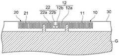
图1是示意性地示出根据本发明第一实施例的通信设备的内部配置的平面图。FIG. 1 is a plan view schematically showing the internal configuration of a communication device according to a first embodiment of the present invention.
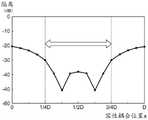
图2A是示出根据本发明第一实施例的通信设备的天线之间的隔离性能的图表。FIG. 2A is a graph showing isolation performance between antennas of the communication device according to the first embodiment of the present invention.
图2B是示出当不包括本发明实施例的配置时天线之间的隔离性能的图表。FIG. 2B is a graph showing the isolation performance between antennas when the configuration of the embodiment of the present invention is not included.
图3是示出本发明第一实施例中的每一个天线的方向性的视图。Fig. 3 is a view showing the directivity of each antenna in the first embodiment of the present invention.
图4是示出本发明第一实施例中的天线之间的相关性的图表。Fig. 4 is a graph showing the correlation between antennas in the first embodiment of the present invention.
图5是示出当馈送点之间的距离改变时隔离性能的改变的图表。FIG. 5 is a graph showing changes in isolation performance when the distance between feeding points is changed.
图6是示出当容性耦合位置改变时隔离性能的改变的图表。FIG. 6 is a graph showing changes in isolation performance when capacitive coupling positions are changed.
图7是示意性地示出根据本发明第二实施例的通信设备的内部配置的平面图。Fig. 7 is a plan view schematically showing the internal configuration of a communication device according to a second embodiment of the present invention.
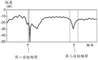
图8是示出根据本发明第二实施例的通信设备的天线之间的隔离性能的图表。8 is a graph showing isolation performance between antennas of a communication device according to a second embodiment of the present invention.
图9是示出本发明的第一变型例的平面图。Fig. 9 is a plan view showing a first modification example of the present invention.
图10是示出本发明的第二变型例的透视图。Fig. 10 is a perspective view showing a second modification example of the present invention.
图11是示出本发明的第三变型例的平面图。Fig. 11 is a plan view showing a third modification example of the present invention.
图12是示出本发明的第四变型例的平面图。Fig. 12 is a plan view showing a fourth modification example of the present invention.
图13是示出本发明的第五变型例的平面图。Fig. 13 is a plan view showing a fifth modification example of the present invention.
图14是示出本发明的第六变型例的平面图。Fig. 14 is a plan view showing a sixth modification example of the present invention.
图15是示出本发明的第七变型例的透视图。Fig. 15 is a perspective view showing a seventh modification example of the present invention.
图16是示出本发明的第八变型例的透视图。Fig. 16 is a perspective view showing an eighth modification of the present invention.
图17是示出本发明的第九变型例的透视图。Fig. 17 is a perspective view showing a ninth modification example of the present invention.
图18是示出本发明的第十变型例的透视图。Fig. 18 is a perspective view showing a tenth modification example of the present invention.
具体实施方式Detailed ways
在下文中,将参照附图详细描述本发明的实施例。Hereinafter, embodiments of the present invention will be described in detail with reference to the accompanying drawings.
[第一实施例][first embodiment]
图1是示意性地示出根据本发明第一实施例的设置在通信设备1a内的多个天线的状态的平面图。通信设备1a的示例包括个人计算机、固定游戏机、便携式游戏机、智能手机和平板计算机。通信设备1a包括第一天线10、第二天线20和基板30。Fig. 1 is a plan view schematically showing a state of a plurality of antennas provided in a
第一天线10和第二天线20中的每一个发送和/或接收无线信号(电磁波),并且用于使通信设备1a与另一通信设备无线通信。在本实施例中,第一天线10和第二天线20发射和接收其频带至少部分相互重叠的无线信号。例如,第一天线10和第二天线20中的一个可用于基于电气和电子工程师学会(IEEE)802.11标准的无线LAN通信,并且第一天线10和第二天线20中的另一个可用于蓝牙通信。可选地,第一天线10和第二天线20都可以用于使用相同标准(诸如基于例如MIMO的技术的无线LAN或蓝牙)通信。可选地,第一天线10和第二天线20可用于在部分相互重叠的预定频带(诸如长期演进(LTE)中的频带12和频带17)中进行通信。可选地,第一天线10和第二天线20可用于相互不同的应用,其中,例如,一个用于传输,并且另一个用于基于公共通信标准的接收。Each of the
在下文中,将第一天线10和第二天线20中的每一个用于发送和接收的无线信号的频带称为目标频带。在本实施例中,假设第一天线10和第二天线20的目标频带基本上彼此相等,并且是5GHz左右的频带。Hereinafter, a frequency band for wireless signals transmitted and received by each of the
基板30是例如安装了处理由第一天线10和第二天线20发送和接收的无线信号的电子电路的电路基板。图1中的阴影部分指示与基板30的接地(参考电势)形成的区域(在下文中称为接地模式G)。第一天线10和第二天线20各自配置有在基板30的外边缘上没有形成接地的区域中形成为平面形状的导体。第一天线10和第二天线20连接到共同的参考电势。图1中的点P1和点P2分别指示第一天线10和第二天线20的馈送点的位置。The
在下文中,将描述本实施例中的第一天线10和第二天线20的特征。如图1所示,第一天线10包括主体部分11和支路部分12。Hereinafter, features of the
主体部分11是用于发送和接收无线信号的部分,其作为第一天线10的原始对象,并且具有用于与目标频带中的无线信号共振的尺寸和形状。在本实施例中,主体部分11具有从馈送点P1向与第二天线20相反延伸的矩形,并且用作单极天线。The
支路部分12具有从主体部分11分支和伸出的细长杆形状。更具体地,支路部分12是在从靠近第二天线20的主体部分11的一侧分支的同时形成的。支路部分12形成为从与馈送点P1的一侧(即,更靠近接地的一侧)相对的主体部分11的一端向第二天线20伸出。支路部分12包括从主体部分11向第二天线20(即,沿着第一天线10和第二天线20对齐的方向)以基本恒定的宽度延伸的延伸部分12a、以及连接到延伸部分12a的尖端的耦合部分12b。换言之,耦合部分12b设置在最靠近第二天线20的位置。耦合部分12b具有在延伸部分12a的尖端弯曲并向接地延伸的形状。通过延伸部分12a和耦合部分12b,支路部分12整体上形成为大致L形状。耦合部分12b的长度短于主体部分11的高度和延伸部分12a的长度,并且沿着面向第二天线20的方向设置。利用该配置,使得沿整个支路部分12的延伸方向的耦合位置(耦合部分12b的位置,最接近第二天线20)处的宽度比在分支位置(延伸部分12a连接到主体部分11的位置)处的宽度更宽。The
与第一天线10类似,第二天线20也包括主体部分21和支路部分22。支路部分22包括延伸部分22a和耦合部分22b。如图1所示,第二天线20具有通过将第一天线10整体横向反转而形成的形状,并且被设置成与第一天线10对称。主体部分21和支路部分22的功能分别类似于第一天线10中的主体部分11和支路部分12。Similar to the
特别地,在本实施例中,支路部分22从主体部分21分支以向第一天线10伸出。在支路部分22的尖端形成的耦合部分22b被设置成面向第一天线10的耦合部分12b。具体地,耦合部分12b和耦合部分22b之间设置有间隔。另外,耦合部分12b和耦合部分22b之间的距离相对较短,使得耦合部分12b和耦合部分22b彼此邻近。这引起耦合部分12b和耦合部分22b之间的容性耦合。在本实施例中,耦合部分12b和耦合部分22b设置成在相同的平面(在本文中,包括第一天线10和第二天线20的平面)中彼此面对。In particular, in the present embodiment, the
利用上述配置,第一天线10和第二天线20总共以四种共振模式共振。这些共振模式的配置由图1中的虚线箭头指示。具体地,第一天线10的主体部分11在第一共振模式中引起共振。该共振实现在目标频带内与第一天线10的无线通信。此外,第二天线20的主体部分21在第二共振模式中引起共振。该共振实现在目标频带内与第二天线20的无线通信。With the configuration described above, the
此外,在从第一天线10的馈送点P1到第二天线20的馈送点P2的第三共振模式中,经由第一天线10的主体部分11和支路部分12、耦合部分12b和耦合部分22b之间的容性耦合、以及第二天线20的支路部分22和主体部分21引起共振。另外,第四共振模式中的共振是在与第三共振模式相反的方向上引起的。第三和第四共振模式中的共振包括与第一和第二共振模式中共振的频率分量接近或重叠的频率分量,因此对抵消第一和第二共振模式中的共振对另一天线的影响起作用。具体地,第三共振模式对第二天线20施加影响,以消除由第一共振模式引起的影响。第四共振模式对第一天线10施加影响,以消除由第二共振模式引起的影响。Furthermore, in the third resonance mode from the feeding point P1 of the
换言之,通过在每一个天线中设置从作为原始对象的主体部分分支的支路部分,以引起共振并且电容性地耦合到另一天线,可以获得减小对另一天线的影响的效果。通过这种配置,天线本身可以改善天线之间的隔离度,而无需在天线外部单独设置短截线或其他组件。此外,第一天线10和第二天线20需要在某种程度上彼此靠近地设置,以使这些天线彼此容性耦合。因此,当使用该配置时,第一天线10和第二天线20之间的距离不必大幅度增加。In other words, by providing in each antenna a branch portion branched from the main body portion as the original object to cause resonance and capacitively coupled to the other antenna, an effect of reducing influence on the other antenna can be obtained. With this configuration, the antenna itself can improve isolation between antennas without the need for separate stubs or other components outside the antenna. Furthermore, the
图2A是示出通过仿真对本实施例中的天线之间的隔离性能的考察结果的图。图的水平轴表示频率,并且垂直轴表示隔离值。这表明,垂直轴上的值越小,天线之间的隔离度越可靠。为了比较的目的,图2B示出了在不提供支路部分12和支路部分22的情况下,两个分别仅配置有主体部分的天线在类似于本实施例设置的情况下的仿真结果。如图2A和2B所示,可以理解,根据本实施例,在目标频带(约5GHz的频带)中改善了隔离。FIG. 2A is a graph showing the results of investigation of isolation performance between antennas in this embodiment by simulation. The horizontal axis of the graph represents frequency, and the vertical axis represents isolation value. This shows that the smaller the value on the vertical axis, the more reliable the isolation between the antennas. For the purpose of comparison, FIG. 2B shows the simulation results of two antennas respectively configured with only the main body part in the case of setting similar to the present embodiment without providing the
当使用该配置时,第一天线10和第二天线20被双对称地设置。因此,天线的方向性基本上也是对称的。图3示出了第一天线10和第二天线20中的每一个的方向性。利用这样的特性,可以在目标频带内将天线之间的相关性系数降低。图4指示第一天线10和第二天线20之间的相关性系数。When using this configuration, the
本申请的发明人通过仿真进一步研究了当与例如每一个天线的形状和设置位置有关的参数改变时隔离性能的改变。研究结果如下所述。The inventors of the present application further studied, by simulation, changes in isolation performance when parameters related to, for example, the shape and placement position of each antenna are changed. The results of the study are described below.
图5示出了当第一天线10的馈送点P1和第二天线20的馈送点P2之间的距离(在下文中称为馈送点之间的距离L)改变时隔离性能的变化。在该图中,水平轴表示馈送点之间的距离L,并且垂直轴表示隔离值。此外,λ表示与目标频带的代表值(例如,频带的中心值或主体部分共振最强烈的频率值)相对应的波长。在本文中,主体部分11和21的形状、耦合部分12b和22b的形状以及耦合部分之间的距离是固定的,并且延伸部分12a和22a的各自长度对应于馈送点之间的距离L的改变以相等的比率改变。FIG. 5 shows changes in isolation performance when the distance between the feed point P1 of the
如图5所示,当馈送点之间的距离L约为1/2λ时,隔离性能得到最大改善。当馈送点之间的距离L小于1/4λ(即天线之间的距离太小)时,支路部分12和22的效果减小。当馈送点间的距离L超过3/4λ时,仍有一定程度效果,但与馈送点间的距离L在1/2λ左右时相比,隔离性能下降。因此,关于对应于目标频带的代表值的波长λ,期望馈送点之间的距离L大于或等于1/4λ且小于或等于3/4λ。注意,在这种情况下,馈送点之间的距离L可以是电长度,而不是物理长度。当介电常数为1时,作为电长度的馈送点之间的距离L与物理距离一致。然而,例如,当构成基板30的电介质的介电常数大于1时,电长度的值变为大于物理距离。因此,当在馈送点P1和馈送点P2之间设置具有大介电常数的电介质时,可以固定所需的电长度,同时减小这些馈送点之间的物理距离。As shown in Figure 5, the isolation performance is most improved when the distance L between the feeding points is about 1/2λ. When the distance L between the feed points is less than 1/4λ (ie, the distance between the antennas is too small), the effects of the
接下来,图6示出了当容性耦合位置(即,耦合部分12b和耦合部分22b彼此面对的位置)改变时隔离性能的改变。在该图中,水平轴表示容性耦合位置x,垂直轴表示隔离值。在本文中,主体部分11和21的形状、耦合部分12b和22b的形状、耦合部分之间的距离和馈送点之间的距离L是固定的,并且调整延伸部分12a和22a的各自长度以改变容性耦合位置。将容性耦合位置最接近主体部分21(当延伸部分22a的长度为零时)的情况表示为x=0。相反,将容性耦合位置最接近主体部分11的情况(当延伸部分12a的长度为零时)表示为x=D。因此,x=1/2D表示延伸部分12a和22a的长度彼此相等的情况,并且容性耦合位置位于主体部分11和主体部分21之间的中心位置处(与主体部分11和主体部分21具有相等距离的位置)。Next, FIG. 6 shows changes in isolation performance when the capacitive coupling position (ie, the position where the
如图6所示,即使在使容性耦合位置更接近天线中的任何一个的状态下,也可以改善隔离性能。然而,当容性耦合位置设置在两个天线的中心附近时,可以特别地改善隔离性能。因此,期望将容性耦合位置设置在1/4D到3/4D范围内的位置处,即,在比到任何一个主体部分的距离更接近主体部分之间的中心的位置处。As shown in FIG. 6 , even in a state where the capacitive coupling position is brought closer to any of the antennas, the isolation performance can be improved. However, isolation performance can be particularly improved when the capacitive coupling position is set near the center of the two antennas. Therefore, it is desirable to set the capacitive coupling position at a position in the range of 1/4D to 3/4D, that is, at a position closer to the center between the main body parts than the distance to any one main body part.
通过使用根据上述本实施例的通信设备1a,除了在目标频带中共振的主体部分,两个天线中的每一个都具有导致与另一支路部分容性耦合的支路部分,从而在不在天线外部提供短截线或其他组件的情况下改善两个天线之间的隔离性能。By using the
[第二实施例][Second embodiment]
随后,将描述根据本发明第二实施例的通信设备1b的配置。注意,在下文中,与第一实施例中的组件相对应的组件被附有相同的参考符号,并且省略对其的详细描述。Subsequently, the configuration of the
与第一实施例类似,根据本实施例的通信设备1b被配置成包括第一天线10、第二天线20和基板30,但在每一个天线的形状上与第一实施例不同,从而区分可以发送和接收的无线信号的频带。具体地,每一个天线使用彼此不同的第一目标频带和第二目标频带来实现无线通信。例如,第一目标频带可以是约2.4GHz的频带,而第二目标频带可以是约5GHz的频带。Similar to the first embodiment, the
图7是示出本实施例中的第一天线10和第二天线20的形状的平面图。如图7所示,在本实施例中,第一天线10被配置成包括主体部分11和支路部分12。主体部分11被配置成包括第一共振部分11a和第二共振部分11d。FIG. 7 is a plan view showing the shapes of the
第一共振部分11a是在第一目标频带中共振的部分。第一共振部分11a被配置成包括从馈送点P1垂直于基板30延伸的基础部分11b、和从基础部分11b的尖端与第二天线20相反地延伸的延伸部分11c。延伸部分11c的尖端具有向馈送点P1弯曲的L形状,从而使得第一共振部分11a整体上具有大致C形状。调整第一共振部分11a的总长度以在第一目标频带中共振。The
第二共振部分11d是在第二频带中共振的部分。第二共振部分11d由从第一共振部分11a的基础部分11b在靠近馈送点P1的位置处分支而形成,并且具有与第二天线20相反地延伸的线性形状。利用这两个共振部分,第一天线10可以在第一目标频带和第二目标频带中的每一个中发射和接收无线信号。The
与第一实施例类似,支路部分12被配置成包括延伸部分12a和耦合部分12b。延伸部分12a从第一共振部分11a的更靠近第二天线20的一侧的一端朝向第二天线20延伸。连接到延伸部分12a的尖端的耦合部分12b被设置成与第二天线20的耦合部分22b留有间隔地邻近。Similar to the first embodiment, the
在本文中,第一共振部分11a的延伸部分11c和支路部分12的延伸部分12a通过从基础部分11b的尖端分支而形成。延伸部分11c的宽度比延伸部分12a的宽度更宽。换言之,在支路部分12从主体部11分支的分支点处,支路部分12的宽度比从分支点向前延伸的主体部分11的宽度更窄。通过这样的形状,流过主体部分11的电流的大小可以大于流过支路部分12的电流的大小。Herein, the
与第一天线10类似,第二天线20也被配置成包括主体部分21和支路部分22。主体部分21被配置成包括第一共振部分21a和第二共振部分22d。第一共振部分21a被配置成包括基础部分21b和延伸部分21c。此外,支路部分22被配置成包括延伸部分22a和耦合部分22b。与第一实施例类似,在本实施例中,第二天线20也具有与第一天线10的形状相似的形状,并且设置成与第一天线10对称。该配置使得设置成彼此邻近的第一天线10的耦合部分12b和第二天线20的耦合部分22b容性耦合,从而通过与第一实施例中的第三共振模式和第四共振模式相似的路径来引起共振。Similar to the
特别地,在本实施例中,通过容性耦合进行的共振模式引起共振,以抵消第一目标频带中的共振和第二目标频带中的共振的影响。因此,通过提供支路部分12和支路部分22,可以在第一目标频带和第二目标频带两者中改善隔离性能。In particular, in the present embodiment, the resonance mode by capacitive coupling causes resonance to cancel the influence of the resonance in the first target frequency band and the resonance in the second target frequency band. Therefore, by providing the
图8是示出本实施例中天线之间的隔离性能的图,并且示出了实际测量结果。如图8所示,通过使用根据本实施例的通信设备1b,第一目标频带(在本文中,是约2.4GHz的频带)和第二目标频带(在本文中,是约5GHz的频带)中的隔离值都得到了改善。此外,还证实了对于各天线的电压驻波比(VSWR)和效率,也可以获得令人满意的性能。FIG. 8 is a graph showing isolation performance between antennas in this embodiment, and shows actual measurement results. As shown in FIG. 8, by using the
注意,同样在本实施例中,容性耦合位置优选地为相对靠近第一天线10和第二天线20之间的中间点的位置。此外,在假定与第一频带的代表值相对应的波长为λ1、并且与第二频带的代表值相对应的波长为λ2的情况下,当馈送点之间的距离L大于或等于1/4λ1且小于或等于3/4λ1时,期望第一目标频段的隔离性能得到改善。此外,当馈送点之间的距离L大于或等于1/4λ2且小于或等于3/4λ2时,期望第二目标频带的隔离性能得到改善。因此,馈送点之间的距离L对于两个波长都满足这些条件是优选的,但是即使馈送点之间的距离L对于两个波长中的任何一个满足该条件,也可以期望特定频带中的隔离性能与不满足任何条件的情况相比可以得到改善。Note that also in this embodiment, the capacitive coupling position is preferably a position relatively close to the middle point between the
如上所述,通过使用根据本实施例的通信设备1b,当在多个目标频带中进行无线通信时,可以在不提供短截线或其他组件的情况下改善每一个频带中的隔离性能。As described above, by using the
[变型例][Modification]
本发明的实施例不限于上述实施例。具体地,支路部分12和支路部分22可以具有各种形状,只要这些形状能够实现天线之间的容性耦合。主体部分11和主体部分21也可以具有各种形状,只要这些形状能够在目标频带中引起共振。支路部分从主体部分分支的位置也不限于远离接地的一侧的端部,并且可以是各种位置。另外,关于天线本身的设置位置,在上述描述中,两个天线以对齐的方式设置在基板的一侧表面上。然而,本发明不限于这种设置。在下文中,将描述适用于根据本发明实施例的通信设备的各种变型例。注意,下面要描述的变型例适用于上面描述的第一实施例和第二实施例中的任何一个,但是会把第一实施例中天线的设置位置和形状被变型例的情况(即,主体部分11和21在单个目标频带中共振的配置的情况)作为具体示例在下文中描述。Embodiments of the present invention are not limited to the above-described embodiments. Specifically, the
图9是示出第一变型例中的每一个天线的形状和设置的平面图。在该第一变型例中,第一天线10和第二天线20被设置成插入在基板30上形成的接地模式G的角(顶点)中。在本文中,两个天线被设置成相对于通过接地模式G的顶点的斜直线对称,并且第一天线10的主体部分11和第二天线20的主体部分21一起形成90度的角度。基于该配置,延伸部分12a具有首先沿平行于第一天线10连接到的接地模式G的一侧的方向延伸,然后向第二天线20弯曲以在中间形成钝角。延伸部分22a具有类似于延伸部分12a的结构,并且延伸部分12a和延伸部分22a被设置成彼此对称。利用这种配置,即使当主体部分11和主体部分21被设置为形成90度角时,耦合部分12b和22b也被留有间隔地邻近地设置,从而使导电耦合成为可能。Fig. 9 is a plan view showing the shape and arrangement of each antenna in the first modification. In this first modification, the
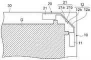
图10是示出第二变型例中的每一个天线的形状和设置的透视图。在上述描述中,第一天线10和第二天线20均以扁平形状形成在基板30上。然而,在该第二变型例中,第一天线10和第二天线20中的每一个由固定在基板30的表面上的扁平导电材料形成,以便沿着基板30的厚度方向升起。同样在该第二变型例中,第一天线10和第二天线20形成在基本相同的平面中。利用该配置,耦合部分12b和耦合部分22b被设置成在相同平面中彼此面对。Fig. 10 is a perspective view showing the shape and arrangement of each antenna in a second modification. In the above description, both the
图11是示出第三变型例中的每一个天线的形状和设置的平面图。该第三变型例在支路部分12和22的各自形状上与第一实施例不同。具体地,支路部分12和22中的每一个具有基本上梯形的形状,并且当从主体部分分支后向其尖端前进时,其宽度变得更宽。同样,在该配置中,在支路部分件12和22中的每一个中,沿着延伸方向的耦合位置(要导电地耦合到另一个的位置)处的宽度比分支位置(要连接到主体部分的位置)处的宽度更宽,从而促进导电耦合。Fig. 11 is a plan view showing the shape and arrangement of each antenna in a third modification. This third modification differs from the first embodiment in the respective shapes of the
图12是示出第四变型例中的每一个天线的形状和设置的平面图。该第四变型例在每一个支路部分12和22到相应的主体部分的连接位置(分支位置)上与上述变型例不同。换言之,支路部分12从主体部分11的更靠近第二天线20的一侧的端部分支。然而,支路部分12不是从远离接地的一侧分支,而是从靠近接地的一侧分支。同样适用于支路部分22。注意,支路部分从主体部分分支的分支位置不限于上述变型例,并且可以是任何位置。Fig. 12 is a plan view showing the shape and arrangement of each antenna in a fourth modification. This fourth modification differs from the above-described modification in the connection position (branch position) of each
图13是示出第五变型例中的每一个天线的形状和设置的平面图。该第五次变型例在主体部分11和21的各自形状上与上述变型例不同。具体地,主体部分11和21中的每一个具有与相应支路部分相反地延伸的杆形状。同样在这种情况下,主体部分11和21使能目标频带中的无线通信。Fig. 13 is a plan view showing the shape and arrangement of each antenna in a fifth modification. This fifth modification differs from the above-described modification in the respective shapes of the
图14是示出第六变型例中的每一个天线的形状和设置的平面图。该第六次变型例在主体部分和支路部分的形状上与上述变型例不同。两个部分都有弯曲多次以迂回的曲折形状。利用这种形状,可以在相对狭窄的范围内使天线的距离变长。这允许配置例如在相对的低频带中以节省空间的方式进行无线通信的天线。注意,在本文中,主体部分和支路部分都具有曲折形状,但是主体部分和支路部分中的任何一个可以具有本变型例中描述的配置。Fig. 14 is a plan view showing the shape and arrangement of each antenna in a sixth modification. This sixth modification differs from the above-described modification in the shapes of the main body portion and the branch portion. Both parts have a zigzag shape that bends multiple times to meander. With this shape, the distance of the antenna can be made long within a relatively narrow range. This allows configuring an antenna for wireless communication in a space-saving manner, for example, in a relatively low frequency band. Note that, herein, both the main body portion and the branch portion have meandering shapes, but either one of the main body portion and the branch portion may have the configuration described in this modification.
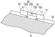
图15是示出第七变型例中的每一个天线的形状和设置的透视图。在该第七变型例中,第一天线10和第二天线20被设置成在彼此相反的方向中插入基板30的接地模式G。利用该配置,延伸部分12a和22a各自具有弯曲以形成90度角的形状,并且在弯曲后在天线之间的中间位置处彼此面对。Fig. 15 is a perspective view showing the shape and arrangement of each antenna in a seventh modification. In this seventh modification, the
此外,在本变型例中,不将耦合部分12b和22b中的每一个形成为具有比相应延伸部分的宽度更宽的宽度,并且其具有与支路部分从主体部分分支的分支位置的宽度相同的宽度。这样,只要能够获得允许通过支路部分的共振模式发生的程度的导电耦合,则不一定将耦合部分形成为具有更宽的宽度。Also, in the present modification, each of the
图16是示出第八变型例中的每一个天线的形状和设置的透视图。在上述所有变型例中,第一天线10和第二天线20设置在同一平面中。注意,在第二变型例中,不将天线设置在基板30上,而是将第一天线10和第二天线20设置在同一平面上以引起导电耦合,同时使耦合部分彼此面对。然而,在该第八变型例中,将第一天线10和第二天线20分别设置在彼此不同且平行的平面上。更具体地,在本文中,假设基板30是多层基板,并且假设第一天线10和第二天线20分别连接到基板30的彼此不同的层,并且各自设置在与所连接的层相同的平面上。Fig. 16 is a perspective view showing the shape and arrangement of each antenna in an eighth modification. In all the variants described above, the
在该变型例中,将耦合部分12b和耦合部分22b设置成在平面视图中彼此重叠(即,从垂直于基板30的表面的方向看)。换言之,在上述变型例中,耦合部分12b和耦合部分22b被设置成在相同平面中彼此面对。相比之下,在本变型例中,耦合部分12b和耦合部分22b沿垂直于基板30的表面的方向(基板30的厚度方向)留有间隔地设置,从而允许这种设置引起导电耦合。这种设置还可以通过导电耦合引起共振,从而改善隔离度。In this modification, the
图17是示出第九变型例中的每一个天线的形状和设置的透视图。在图17中的该变型例中,与第八变型例类似,将第一天线10和第二天线20分别设置在彼此不同且平行的平面上。将支路部分12的尖端处的耦合部分12b和支路部分22的尖端处的耦合部分22b设置成在平面视图中留有间隔地彼此重叠。Fig. 17 is a perspective view showing the shape and arrangement of each antenna in a ninth modification. In this modified example in FIG. 17 , similar to the eighth modified example, the
同样,在本变型例中,与第七变型例类似,耦合部分12b和22b中的每一个的宽度基本上与对应分支位置处的宽度一致。然而,通过调整平面视图中的重叠区域,可以保证所需的导电耦合。Also in the present modification, similarly to the seventh modification, the width of each of the
图18是示出第十变型例的透视图。在上述变型例中,每一个天线的形状和配置都与第一实施例中的不同。然而,在本变型例中,第一天线10和第二天线20的形状和配置与第一实施例中的类似,但是形成在基板30上的接地模式G的形状与第一实施例中的不同。如图18所示,接地模式G的形状可以是任何形状,并且不同于上述变型例,可将第一天线10和第二天线20设置在与接地模式G邻近的位置。注意,第一天线10和第二天线20应连接到相同的接地,以通过导电耦合引起共振。Fig. 18 is a perspective view showing a tenth modification. In the modification described above, the shape and configuration of each antenna are different from those in the first embodiment. However, in this modified example, the shapes and configurations of the
注意,可以以任何方式组合和应用上述每一个变型例的特征。例如,可将每一个具有曲折形状的支路部分的天线分别连接到多层基板中彼此不同的层。Note that the features of each modification described above may be combined and applied in any manner. For example, antennas each having a zigzag-shaped branch portion may be respectively connected to layers different from each other in the multilayer substrate.
[参考符号列表][List of Reference Symbols]
1a,1b通信设备,1a, 1b communication equipment,
10第一天线,10 first antenna,
20第二天线,20 second antenna,
11,21主体部分,11, 21 main part,
12,22支路部分,12, 22 branch road part,
12a,22a延伸部分,12a, 22a extension,
12b,22b耦合部分,12b, 22b coupling part,
30基板。30 substrates.
Claims (4)
Translated fromChineseApplications Claiming Priority (3)
| Application Number | Priority Date | Filing Date | Title |
|---|---|---|---|
| JP2017-230134 | 2017-11-30 | ||
| JP2017230134 | 2017-11-30 | ||
| PCT/JP2018/044238WO2019107553A1 (en) | 2017-11-30 | 2018-11-30 | Communication device |
Publications (2)
| Publication Number | Publication Date |
|---|---|
| CN111373603A CN111373603A (en) | 2020-07-03 |
| CN111373603Btrue CN111373603B (en) | 2022-11-01 |
Family
ID=66664911
Family Applications (1)
| Application Number | Title | Priority Date | Filing Date |
|---|---|---|---|
| CN201880075685.2AActiveCN111373603B (en) | 2017-11-30 | 2018-11-30 | Communication device |
Country Status (5)
| Country | Link |
|---|---|
| US (1) | US11233322B2 (en) |
| EP (1) | EP3719928A4 (en) |
| JP (1) | JP6903158B2 (en) |
| CN (1) | CN111373603B (en) |
| WO (1) | WO2019107553A1 (en) |
Families Citing this family (1)
| Publication number | Priority date | Publication date | Assignee | Title |
|---|---|---|---|---|
| DE102019124713B4 (en)* | 2018-11-27 | 2025-08-14 | Samsung Electronics Co., Ltd. | Devices and methods for controlling exposure to wireless communications |
Citations (3)
| Publication number | Priority date | Publication date | Assignee | Title |
|---|---|---|---|---|
| CN101779332A (en)* | 2007-08-09 | 2010-07-14 | 松下电器产业株式会社 | Antenna device and portable wireless device |
| CN103368626A (en)* | 2012-04-03 | 2013-10-23 | 财团法人工业技术研究院 | Multi-frequency multi-antenna system and communication device thereof |
| CN103688406A (en)* | 2011-06-01 | 2014-03-26 | 讯宝科技公司 | Low Profile Multiband Antenna for Wireless Communication Devices |
Family Cites Families (9)
| Publication number | Priority date | Publication date | Assignee | Title |
|---|---|---|---|---|
| KR100699472B1 (en)* | 2005-09-27 | 2007-03-26 | 삼성전자주식회사 | Flat Panel Array Antenna with Isolation Element |
| US8937578B2 (en) | 2009-09-01 | 2015-01-20 | Skycross, Inc. | High isolation antenna system |
| US8890763B2 (en)* | 2011-02-21 | 2014-11-18 | Funai Electric Co., Ltd. | Multiantenna unit and communication apparatus |
| JP5626024B2 (en)* | 2011-03-02 | 2014-11-19 | 船井電機株式会社 | Multi-antenna device and communication device |
| JP2013126120A (en)* | 2011-12-15 | 2013-06-24 | Samsung Yokohama Research Institute Co Ltd | Antenna device, and radio communication device |
| TW201511407A (en)* | 2013-09-05 | 2015-03-16 | Quanta Comp Inc | Antenna module |
| TWM478254U (en) | 2013-12-19 | 2014-05-11 | Tongda Comm Co Ltd | Inverted F type antenna containing insulation element |
| CN205452544U (en)* | 2016-01-07 | 2016-08-10 | 中磊电子(苏州)有限公司 | Antenna device |
| TWI618296B (en)* | 2017-03-15 | 2018-03-11 | 智易科技股份有限公司 | Antenna structure |
- 2018
- 2018-11-30CNCN201880075685.2Apatent/CN111373603B/enactiveActive
- 2018-11-30USUS16/765,211patent/US11233322B2/enactiveActive
- 2018-11-30JPJP2019556755Apatent/JP6903158B2/enactiveActive
- 2018-11-30EPEP18883585.4Apatent/EP3719928A4/enactivePending
- 2018-11-30WOPCT/JP2018/044238patent/WO2019107553A1/ennot_activeCeased
Patent Citations (3)
| Publication number | Priority date | Publication date | Assignee | Title |
|---|---|---|---|---|
| CN101779332A (en)* | 2007-08-09 | 2010-07-14 | 松下电器产业株式会社 | Antenna device and portable wireless device |
| CN103688406A (en)* | 2011-06-01 | 2014-03-26 | 讯宝科技公司 | Low Profile Multiband Antenna for Wireless Communication Devices |
| CN103368626A (en)* | 2012-04-03 | 2013-10-23 | 财团法人工业技术研究院 | Multi-frequency multi-antenna system and communication device thereof |
Also Published As
| Publication number | Publication date |
|---|---|
| JPWO2019107553A1 (en) | 2020-11-26 |
| WO2019107553A1 (en) | 2019-06-06 |
| JP6903158B2 (en) | 2021-07-14 |
| US20200280126A1 (en) | 2020-09-03 |
| US11233322B2 (en) | 2022-01-25 |
| EP3719928A4 (en) | 2021-08-18 |
| EP3719928A1 (en) | 2020-10-07 |
| CN111373603A (en) | 2020-07-03 |
Similar Documents
| Publication | Publication Date | Title |
|---|---|---|
| US9590304B2 (en) | Broadband antenna | |
| JP6446547B2 (en) | Stripline coupled antenna with periodic slots for wireless electronic devices | |
| KR101505595B1 (en) | Microstrip chip antenna with top loading structure | |
| KR20120138758A (en) | Antennas with novel current distribution and radiation patterns, for enhanced antenna isolation | |
| CN109075436A (en) | Ultra wideband dual polarization radiating element for antenna for base station | |
| EP3214697B1 (en) | Antenna and antenna module comprising the same | |
| CN105917524A (en) | Antenna directivity control system and wireless device provided with same | |
| TW201345177A (en) | Multiple-input multiple-output antenna | |
| TW201433000A (en) | Antenna assembly and wireless communication device having the same | |
| US20170170555A1 (en) | Decoupled Antennas For Wireless Communication | |
| TWI487191B (en) | Antenna system | |
| US10283869B2 (en) | MIMO antenna and wireless device | |
| JP2009111959A (en) | Parallel 2-wire antenna and wireless communication device | |
| US20090015506A1 (en) | Planar antenna | |
| CN101378144A (en) | Radio apparatus and antenna thereof | |
| US9660329B2 (en) | Directional antenna | |
| CN111373603B (en) | Communication device | |
| CN112673522B (en) | Antenna and wireless communication device | |
| JP5324608B2 (en) | Multiband antenna | |
| JP6548112B2 (en) | Broadband antenna | |
| JP6183269B2 (en) | Antenna device and portable wireless terminal equipped with the same | |
| CN113875087A (en) | Antenna units and communication equipment | |
| TWI580111B (en) | Communication device | |
| JP7278158B2 (en) | antenna | |
| JP6059779B1 (en) | Dipole antenna and manufacturing method thereof |
Legal Events
| Date | Code | Title | Description |
|---|---|---|---|
| PB01 | Publication | ||
| PB01 | Publication | ||
| SE01 | Entry into force of request for substantive examination | ||
| SE01 | Entry into force of request for substantive examination | ||
| GR01 | Patent grant | ||
| GR01 | Patent grant |