CN1113735C - Rapid prototyping system with filament supply spool monitoring - Google Patents
Rapid prototyping system with filament supply spool monitoringDownload PDFInfo
- Publication number
- CN1113735C CN1113735CCN99802420ACN99802420ACN1113735CCN 1113735 CCN1113735 CCN 1113735CCN 99802420 ACN99802420 ACN 99802420ACN 99802420 ACN99802420 ACN 99802420ACN 1113735 CCN1113735 CCN 1113735C
- Authority
- CN
- China
- Prior art keywords
- fiber
- spool
- fibers
- modeling
- extrusion head
- Prior art date
- Legal status (The legal status is an assumption and is not a legal conclusion. Google has not performed a legal analysis and makes no representation as to the accuracy of the status listed.)
- Expired - Lifetime
Links
- 238000012544monitoring processMethods0.000titledescription2
- 239000000835fiberSubstances0.000claimsabstractdescription128
- 239000000463materialSubstances0.000claimsdescription71
- 238000001125extrusionMethods0.000claimsdescription65
- 238000000151depositionMethods0.000claimsdescription5
- 238000010276constructionMethods0.000claimsdescription3
- 238000012546transferMethods0.000claimsdescription2
- 239000012768molten materialSubstances0.000claims2
- 230000013011matingEffects0.000claims1
- 239000010410layerSubstances0.000description23
- 239000003570airSubstances0.000description18
- 238000010438heat treatmentMethods0.000description18
- 238000013016dampingMethods0.000description13
- 238000001035dryingMethods0.000description9
- 229910052751metalInorganic materials0.000description5
- 239000002184metalSubstances0.000description5
- 238000000034methodMethods0.000description5
- 239000000203mixtureSubstances0.000description5
- 239000004676acrylonitrile butadiene styreneSubstances0.000description4
- 230000006870functionEffects0.000description4
- 230000005291magnetic effectEffects0.000description4
- 238000007789sealingMethods0.000description4
- 229910000831SteelInorganic materials0.000description3
- 238000013461designMethods0.000description3
- 150000002739metalsChemical class0.000description3
- 239000007787solidSubstances0.000description3
- 239000010959steelSubstances0.000description3
- 229920002994synthetic fiberPolymers0.000description3
- 239000002699waste materialSubstances0.000description3
- 229910000906BronzeInorganic materials0.000description2
- RYGMFSIKBFXOCR-UHFFFAOYSA-NCopperChemical compound[Cu]RYGMFSIKBFXOCR-UHFFFAOYSA-N0.000description2
- PXHVJJICTQNCMI-UHFFFAOYSA-NNickelChemical compound[Ni]PXHVJJICTQNCMI-UHFFFAOYSA-N0.000description2
- RTAQQCXQSZGOHL-UHFFFAOYSA-NTitaniumChemical compound[Ti]RTAQQCXQSZGOHL-UHFFFAOYSA-N0.000description2
- 229920000122acrylonitrile butadiene styrenePolymers0.000description2
- 229910052782aluminiumInorganic materials0.000description2
- XAGFODPZIPBFFR-UHFFFAOYSA-NaluminiumChemical compound[Al]XAGFODPZIPBFFR-UHFFFAOYSA-N0.000description2
- 238000005452bendingMethods0.000description2
- DMFGNRRURHSENX-UHFFFAOYSA-Nberyllium copperChemical compound[Be].[Cu]DMFGNRRURHSENX-UHFFFAOYSA-N0.000description2
- 230000015572biosynthetic processEffects0.000description2
- 239000010974bronzeSubstances0.000description2
- 239000002131composite materialSubstances0.000description2
- 238000011960computer-aided designMethods0.000description2
- 239000004020conductorSubstances0.000description2
- 229910052802copperInorganic materials0.000description2
- 239000010949copperSubstances0.000description2
- KUNSUQLRTQLHQQ-UHFFFAOYSA-Ncopper tinChemical compound[Cu].[Sn]KUNSUQLRTQLHQQ-UHFFFAOYSA-N0.000description2
- 238000010586diagramMethods0.000description2
- 239000002657fibrous materialSubstances0.000description2
- 239000011888foilSubstances0.000description2
- 239000011521glassSubstances0.000description2
- PCHJSUWPFVWCPO-UHFFFAOYSA-NgoldChemical compound[Au]PCHJSUWPFVWCPO-UHFFFAOYSA-N0.000description2
- 229910052737goldInorganic materials0.000description2
- 239000010931goldSubstances0.000description2
- 239000011133leadSubstances0.000description2
- 239000007788liquidSubstances0.000description2
- 238000012423maintenanceMethods0.000description2
- 239000003550markerSubstances0.000description2
- 238000002844meltingMethods0.000description2
- 230000008018meltingEffects0.000description2
- BASFCYQUMIYNBI-UHFFFAOYSA-NplatinumChemical compound[Pt]BASFCYQUMIYNBI-UHFFFAOYSA-N0.000description2
- 229920003223poly(pyromellitimide-1,4-diphenyl ether)Polymers0.000description2
- 239000011343solid materialSubstances0.000description2
- 239000010936titaniumSubstances0.000description2
- 229910052719titaniumInorganic materials0.000description2
- 239000001993waxSubstances0.000description2
- -1ABS compoundChemical class0.000description1
- 229910001369BrassInorganic materials0.000description1
- 239000004593EpoxySubstances0.000description1
- FYYHWMGAXLPEAU-UHFFFAOYSA-NMagnesiumChemical compound[Mg]FYYHWMGAXLPEAU-UHFFFAOYSA-N0.000description1
- PWHULOQIROXLJO-UHFFFAOYSA-NManganeseChemical compound[Mn]PWHULOQIROXLJO-UHFFFAOYSA-N0.000description1
- ZOKXTWBITQBERF-UHFFFAOYSA-NMolybdenumChemical compound[Mo]ZOKXTWBITQBERF-UHFFFAOYSA-N0.000description1
- 239000004793PolystyreneSubstances0.000description1
- BQCADISMDOOEFD-UHFFFAOYSA-NSilverChemical compound[Ag]BQCADISMDOOEFD-UHFFFAOYSA-N0.000description1
- 239000004809TeflonSubstances0.000description1
- 229920006362Teflon®Polymers0.000description1
- 230000001133accelerationEffects0.000description1
- NIXOWILDQLNWCW-UHFFFAOYSA-Nacrylic acid groupChemical groupC(C=C)(=O)ONIXOWILDQLNWCW-UHFFFAOYSA-N0.000description1
- XECAHXYUAAWDEL-UHFFFAOYSA-Nacrylonitrile butadiene styreneChemical compoundC=CC=C.C=CC#N.C=CC1=CC=CC=C1XECAHXYUAAWDEL-UHFFFAOYSA-N0.000description1
- 239000000853adhesiveSubstances0.000description1
- 230000001070adhesive effectEffects0.000description1
- 229910045601alloyInorganic materials0.000description1
- 239000000956alloySubstances0.000description1
- 239000004411aluminiumSubstances0.000description1
- 239000012080ambient airSubstances0.000description1
- 235000013871bee waxNutrition0.000description1
- 239000012166beeswaxSubstances0.000description1
- 239000010951brassSubstances0.000description1
- 239000002775capsuleSubstances0.000description1
- 238000005266castingMethods0.000description1
- 230000015556catabolic processEffects0.000description1
- 238000004140cleaningMethods0.000description1
- 239000003086colorantSubstances0.000description1
- 238000004891communicationMethods0.000description1
- 239000000470constituentSubstances0.000description1
- 238000001816coolingMethods0.000description1
- 230000008021depositionEffects0.000description1
- 230000000994depressogenic effectEffects0.000description1
- 230000000694effectsEffects0.000description1
- 125000003700epoxy groupChemical group0.000description1
- 239000000945fillerSubstances0.000description1
- 239000002783friction materialSubstances0.000description1
- 239000011344liquid materialSubstances0.000description1
- 239000011777magnesiumSubstances0.000description1
- 229910052749magnesiumInorganic materials0.000description1
- 239000011572manganeseSubstances0.000description1
- 229910052748manganeseInorganic materials0.000description1
- 238000004519manufacturing processMethods0.000description1
- 230000007246mechanismEffects0.000description1
- 229910001092metal group alloyInorganic materials0.000description1
- 229910052750molybdenumInorganic materials0.000description1
- 239000011733molybdenumSubstances0.000description1
- 229910052759nickelInorganic materials0.000description1
- 239000012188paraffin waxSubstances0.000description1
- 235000019809paraffin waxNutrition0.000description1
- 235000019271petrolatumNutrition0.000description1
- 239000010957pewterSubstances0.000description1
- 229910000498pewterInorganic materials0.000description1
- 239000004033plasticSubstances0.000description1
- 229920003023plasticPolymers0.000description1
- 229910052697platinumInorganic materials0.000description1
- 229920000647polyepoxidePolymers0.000description1
- 229920002223polystyrenePolymers0.000description1
- 238000003825pressingMethods0.000description1
- 229910052709silverInorganic materials0.000description1
- 239000004332silverSubstances0.000description1
- 239000002356single layerSubstances0.000description1
- 238000007711solidificationMethods0.000description1
- 230000008023solidificationEffects0.000description1
- 239000007858starting materialSubstances0.000description1
- 238000003860storageMethods0.000description1
- 239000000758substrateSubstances0.000description1
- 239000012815thermoplastic materialSubstances0.000description1
- 229920005992thermoplastic resinPolymers0.000description1
- WFKWXMTUELFFGS-UHFFFAOYSA-NtungstenChemical compound[W]WFKWXMTUELFFGS-UHFFFAOYSA-N0.000description1
- 229910052721tungstenInorganic materials0.000description1
- 239000010937tungstenSubstances0.000description1
- 235000012431wafersNutrition0.000description1
Images


Classifications
- B—PERFORMING OPERATIONS; TRANSPORTING
- B33—ADDITIVE MANUFACTURING TECHNOLOGY
- B33Y—ADDITIVE MANUFACTURING, i.e. MANUFACTURING OF THREE-DIMENSIONAL [3-D] OBJECTS BY ADDITIVE DEPOSITION, ADDITIVE AGGLOMERATION OR ADDITIVE LAYERING, e.g. BY 3-D PRINTING, STEREOLITHOGRAPHY OR SELECTIVE LASER SINTERING
- B33Y30/00—Apparatus for additive manufacturing; Details thereof or accessories therefor
- B—PERFORMING OPERATIONS; TRANSPORTING
- B29—WORKING OF PLASTICS; WORKING OF SUBSTANCES IN A PLASTIC STATE IN GENERAL
- B29C—SHAPING OR JOINING OF PLASTICS; SHAPING OF MATERIAL IN A PLASTIC STATE, NOT OTHERWISE PROVIDED FOR; AFTER-TREATMENT OF THE SHAPED PRODUCTS, e.g. REPAIRING
- B29C64/00—Additive manufacturing, i.e. manufacturing of three-dimensional [3D] objects by additive deposition, additive agglomeration or additive layering, e.g. by 3D printing, stereolithography or selective laser sintering
- B29C64/10—Processes of additive manufacturing
- B29C64/106—Processes of additive manufacturing using only liquids or viscous materials, e.g. depositing a continuous bead of viscous material
- B29C64/118—Processes of additive manufacturing using only liquids or viscous materials, e.g. depositing a continuous bead of viscous material using filamentary material being melted, e.g. fused deposition modelling [FDM]
- B—PERFORMING OPERATIONS; TRANSPORTING
- B29—WORKING OF PLASTICS; WORKING OF SUBSTANCES IN A PLASTIC STATE IN GENERAL
- B29C—SHAPING OR JOINING OF PLASTICS; SHAPING OF MATERIAL IN A PLASTIC STATE, NOT OTHERWISE PROVIDED FOR; AFTER-TREATMENT OF THE SHAPED PRODUCTS, e.g. REPAIRING
- B29C64/00—Additive manufacturing, i.e. manufacturing of three-dimensional [3D] objects by additive deposition, additive agglomeration or additive layering, e.g. by 3D printing, stereolithography or selective laser sintering
- B29C64/20—Apparatus for additive manufacturing; Details thereof or accessories therefor
- B29C64/255—Enclosures for the building material, e.g. powder containers
- B29C64/259—Interchangeable
- B—PERFORMING OPERATIONS; TRANSPORTING
- B33—ADDITIVE MANUFACTURING TECHNOLOGY
- B33Y—ADDITIVE MANUFACTURING, i.e. MANUFACTURING OF THREE-DIMENSIONAL [3-D] OBJECTS BY ADDITIVE DEPOSITION, ADDITIVE AGGLOMERATION OR ADDITIVE LAYERING, e.g. BY 3-D PRINTING, STEREOLITHOGRAPHY OR SELECTIVE LASER SINTERING
- B33Y40/00—Auxiliary operations or equipment, e.g. for material handling
Landscapes
- Chemical & Material Sciences (AREA)
- Engineering & Computer Science (AREA)
- Materials Engineering (AREA)
- Manufacturing & Machinery (AREA)
- Physics & Mathematics (AREA)
- Mechanical Engineering (AREA)
- Optics & Photonics (AREA)
Abstract
Translated fromChineseDescription
Translated fromChinese本发明涉及三维原机建造领域。特别是,本发明是一种通过从挤压头到底部多层沉积液态材料来形成预先设计的三维目标的快速建模系统。材料是经由挑选的且其温度可控以便于其在挤压头上能固化或能分发到底部,用多层的逐步建立形成所期望的目标。在本发明中,用从卷轴供应的纤维来形成三维目标,其中的卷轴具有一个用于保存有关卷轴上的纤维的类型和数量的数据的相关电路。The invention relates to the field of three-dimensional prototype construction. In particular, the present invention is a rapid modeling system for forming predesigned three-dimensional objects by depositing liquid material in multiple layers from the extrusion head to the bottom. The material is selected and its temperature controlled so that it can be solidified on the extrusion head or dispensed to the bottom, with the gradual build-up of multiple layers to form the desired target. In the present invention, a three-dimensional object is formed from a supply of fiber from a spool having an associated circuit for storing data regarding the type and amount of fiber on the spool.
快速建模系统包括根据设计数据而制造三维目标,其中数据由计算机辅助设计系统(CAD)提供。装置的例子及通过多层沉积固态材料进行三维目标的快速建模的方法在Crump的美国专利5,121,329,授予Batchelder的美国专利5,303,141,Crump的美国专利5,340,433,Batchelder的美国专利5,402,351,Batchelder的美国专利5,426,722,授予Crump的美国专利5,503,785,以及授予Abrams的美国专利5,587,913中进行了描述,所有这些专利都转让给了Stratasys有限公司。具有一个纤维进给或一个固体棒进给的快速建模系统在Crump的329专利及Crump的433专利中进行了描述。Rapid prototyping systems involve the fabrication of three-dimensional objects from design data provided by a computer-aided design system (CAD). Examples of devices and methods for rapid modeling of three-dimensional objects by depositing multiple layers of solid material are in US Patent 5,121,329 to Crump, US Patent 5,303,141 to Batchelder, US Patent 5,340,433 to Crump, US Patent 5,402,351 to Batchelder, US Patent 5,426,722 to Batchelder , US Patent 5,503,785 to Crump, and US Patent 5,587,913 to Abrams, all of which are assigned to Stratasys, Inc. Rapid prototyping systems with a fiber feed or a solid rod feed are described in Crump's '329 patent and Crump's '433 patent.
在使用一个固体棒进给的快速建模系统中,建模材料的棒或“晶片”通常储存在磁带上,其中磁带把棒分发到系统中,如正在受理中的转让给Stratasys有限公司的申请No.08/556,583所描述的。在使用纤维流动的快速建模系统中,绕纤维卷轴缠绕的纤维长度提供给系统。In rapid prototyping systems using a solid rod feed, rods or "wafers" of modeling material are typically stored on magnetic tape, which dispenses the rods into the system, as in pending application assigned to Stratasys, Inc. As described in No. 08/556,583. In rapid modeling systems using fiber flow, the length of fiber wound around a fiber spool is supplied to the system.
在使用纤维进给或固体棒进给的过程中,控制快速建模系统以将建模材料数量的踪迹保存在磁带上或卷轴上是我们所希望的。对于控制系统而言,知道在磁带上或卷轴上的建模材料的类型,以及用于分发材料的正确参数也是我们所希望的。In processes using fiber feed or solid rod feed, it is desirable to control the rapid build system to keep a trace of the amount of material built on tape or reel. It is also desirable for the control system to know the type of build material on tape or reel, and the correct parameters for dispensing the material.
一个分发到具有一个电子可读可写记忆装置的磁带上的棒在正在受理的申请No.08/556,583中进行了描述,其中电子可读可写记忆装置给控制系统提供数据。记忆装置安装在磁带上,以便制造电子触点在人工插入磁带时通过联接件控制系统。记忆仪器作为一个电子标记进行工作,其中电子标记通知系统磁带上的材料类型,分发材料的正确挤压参数,当前磁带中棒的个数,以及磁带的连续个数。A stick dispensed onto magnetic tape having an EROM providing data to a control system is described in pending application Ser. No. 08/556,583. The memory device is mounted on the tape to make electrical contacts to control the system through the connectors when the tape is manually inserted. The memory instrument works as an electronic marker, where the electronic marker notifies the system of the type of material on the tape, the correct extrusion parameters for the dispensed material, the number of rods currently in the tape, and the consecutive number of tapes.
本发明是一种纤维卷轴及一种提供纤维的快速建模系统,其中系统提供了一个监控关于纤维卷轴上纤维的数据的电路。特别是,本发明提供了有关卷轴上的纤维类型和数量的数据,并在如果纤维的类型与目标规格数据所允许的材料类型不匹配时,或在卷轴上纤维的数量不够建立所期望的目标时,通知操作者。本发明的卷轴还在纤维完全从卷轴上移开之前阻止系统的操作,以便于操作者可以抓住纤维并把纤维从纤维驱动器和挤压头上移开,从而利于取下用过的卷轴和纤维并随后用新纤维卷轴替换。The present invention is a fiber spool and a rapid modeling system for providing fibers, wherein the system provides a circuit for monitoring data about the fibers on the fiber spool. In particular, the present invention provides data regarding the type and amount of fiber on the spool and establishes the desired target if the type of fiber does not match the type of material allowed by the target specification data, or the amount of fiber on the spool is insufficient. , notify the operator. The spool of the present invention also prevents operation of the system until the fiber is completely removed from the spool so that the operator can grab the fiber and remove it from the fiber drive and extrusion head, thereby facilitating removal of the used spool and fiber and then replace it with a new fiber spool.
图1是本发明优选实施例的一个外部正视图,示出了处于建造状态的系统。Figure 1 is an external elevation view of the preferred embodiment of the present invention, showing the system in the as-built state.
图2是本发明优选实施例的一个右侧外部正视图。Figure 2 is a right side exterior elevation view of the preferred embodiment of the present invention.
图3是本发明优选实施例的一个左侧外部正视图。Figure 3 is a left side exterior elevation view of the preferred embodiment of the present invention.
图4是一个建模封壳的一正视图,示出了处于建造状态的系统。Figure 4 is an elevational view of a modeling enclosure showing the system in the as-built state.
图5是本发明优选实施例的控制系统的电路方框图。Fig. 5 is an electrical block diagram of the control system of the preferred embodiment of the present invention.
图6是建模封壳的局部分解立体图,示出了处于建造位置的建模挤压头。Figure 6 is a partially exploded perspective view of the modeling capsule showing the modeling extrusion head in a build position.
图6A是图5的一部分,示出真空平台槽的一个详细部位图。FIG. 6A is a portion of FIG. 5 showing a detailed view of the vacuum platform tank.
图6B是图5的一部分,示出线性电机的气体轴承的一个详细部位图。FIG. 6B is a portion of FIG. 5 showing a detailed view of the gas bearing of the linear motor.
图7是图2和图3所示的纤维转轴和纤维卷轴的一个分解图。Figure 7 is an exploded view of the fiber shaft and fiber spool shown in Figures 2 and 3 .
图7A是一个EEPROM板的一个外向立体图。Figure 7A is an outward perspective view of an EEPROM board.
图8是建模挤压头的一个正视图,其中局部为剖视图。Figure 8 is a front view of a modeling extrusion head, partly in section.
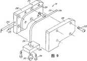
图9是一个液化器的分解图。Figure 9 is an exploded view of a liquefier.
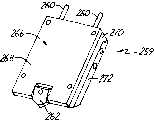
图10A和10B示出了一个变化的液化器实施例。Figures 10A and 10B show an alternate liquefier embodiment.
如图1所示,在优选实施例中,快速建模系统10包含在一个机箱12中。在机箱12的前边、左边和右边有挡板及盖板。在机箱12的前边有一个封挡板14,封挡板14的右边有一个靠模废物托架挡板16,靠模废物托架挡板16的右边有一个触摸屏显示板21,封挡板14的左边有一个支撑废物托架挡板18,而在封挡板14的下边有一个平台盖板20。一个靠模干燥箱挡板22及一个电子仓挡板24位于机箱12的右手边。一个支撑干燥箱挡板26位于机箱12左手边的压缩机仓盖板28之上。In the preferred embodiment,
机箱12的右手边上部容装了一个靠模挤压装置30,该装置包括一个安装在靠模x-y压机33下面并且与靠模臂34的端部相连的靠模挤压头32,其中靠模臂34绕建模枢轴接头36旋转。建模挤压装置30接收来自建模纤维卷轴42的建模材料纤维40,其中卷轴42安装在建模干燥箱45(图2)中位于枢轴接头36之下并且可通过建模干燥箱挡板22获得。干燥箱45维持低湿度的条件以使纤维40的状态达到最佳。建模挤压装置30用于把建模材料分层分发到底层60上。安装在干燥箱45里的建模转轴43上的建模纤维卷轴42在图2中有更清楚的显示。The upper right hand side of the cabinet 12 houses a
机箱12的左手边容装了一个支撑挤压装置44,该装置包括一个安在支撑x-y压机52的下面并与支撑臂48的端部相连的支撑挤压头46,其中支撑臂48绕支撑枢轴接头50旋转。支撑挤压装置44接收来自支撑纤维卷轴56的支撑材料纤维54,其中卷轴56位于支撑纤维干燥箱57(图3)中位于支撑枢轴接头50下面并且可通过支撑干燥箱挡板26获得。干燥箱57维持低湿度的条件以使纤维54的状态达到最佳。支撑挤压装置44用于分层地分发建模材料。安装在干燥箱57里的支撑转轴58上的支撑纤维卷轴56在图3中有更清楚的显示。The left hand side of the cabinet 12 accommodates a
由建模挤压装置30分层挤出的建模材料形成目标64。当目标建造时支撑材料用于支撑任何悬挂部。在建造目标的过程中,不能直接由建模材料支撑在最终几何形状的悬挂部或部分需要一个支撑结构。支撑纤维54供给支撑挤压头46,其中挤压头46用于沉积材料以提供所需的支撑。支撑材料如建模材料被沉积在多层中。The modeling material extruded in layers by the
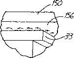
在建造目标时,每次仅有一个挤压装置处于激活的挤压状态。在图1中,示出系统10正在建造一个三维目标64,其中,建模挤压装置30处于激活的建造状态,而支撑挤压装置44处于休止位置。当建模挤压装置30处于激活状态时,建模纤维40经由臂34穿过臂34到达挤压头32,并于此加热成为液体状态。处于熔化状态的建模材料的层次由头32通过一个液化器59沉积,其中液化器59突出通过头32的底面到达底层60上。底层60由一个真空压盘62支撑且被真空力保持到位。当支撑挤压装置44处于激活的建造状态时,支撑挤压头46同样接收经过臂48的支撑纤维54,并将其加热成为液体状态。处于熔化状态的支撑材料的层次由头46通过一个液化器59沉积,其中液化器59突出通过头32的底面到达底层60上。When building a target, only one extrusion is active at a time. In FIG. 1 ,
建模的纤维及支撑材料都是一种固体材料,该固体材料可以在其固化温度之上相对迅速地被加热,且可以在从挤压头分发后以一个略低的温度迅速凝固。为建模材料选择一种在贮存时自身具有相对高的粘附力的成分。为支撑材料选择一种在贮存时自身具有相对低的粘附力的成分,这样支撑材料同建模材料一起形成一个不牢固的、易碎的结合物。当目标完成时,支撑材料由操作员打破,留下完整的由建模材料形成的目标。Both the modeled fiber and the support material are a solid material that can be heated relatively quickly above its solidification temperature and solidify quickly at a slightly lower temperature after being dispensed from the extrusion head. Choose a composition for the build material that itself has relatively high adhesion when stored. A composition is selected for the support material that itself has relatively low adhesion in storage so that the support material forms a weak, brittle bond with the build material. When the target is complete, the support material is broken by the operator, leaving the target formed of the modeling material intact.
建模材料最好是热塑性材料。可以用于建模材料纤维的其他材料包括蜂蜡、铸造蜡、可加工的及工业蜡、石蜡、各种热塑性树脂、金属及金属合金。适用的金属包括银、金、铂、镍、这些金属的合金、铝、铜、金、铅、镁、钢、钛、白蜡、锰及青铜。玻璃及独特的康宁玻璃也是可以的。化学合成材料,包括二部分的环氧树脂也是适用的。已发现的特别适用的一种建模材料是丙烯腈-丁二烯-苯乙烯(ABS)的合成物。已发现的特别适用于支撑材料的材料是在丙烯腈-丁二烯-苯乙烯(ABS)合成物中加入聚苯乙烯共聚物作为一种填充物(达到约80%),以产生ABS合成物的低表面能量,并提供一种低内聚力和低粘附力的材料。两种材料的纤维都最好是一种直径非常小,在0.070英寸数量级的材料。但是,纤维的直径可以是0.001英寸那么小。The modeling material is preferably a thermoplastic material. Other materials that can be used for modeling material fibers include beeswax, casting waxes, processable and industrial waxes, paraffin waxes, various thermoplastic resins, metals and metal alloys. Suitable metals include silver, gold, platinum, nickel, alloys of these metals, aluminium, copper, gold, lead, magnesium, steel, titanium, pewter, manganese and bronze. Glass and the unique Corning glass are also available. Chemically synthetic materials, including two-part epoxies, are also suitable. One build material that has been found to be particularly suitable is the acrylonitrile-butadiene-styrene (ABS) composite. A material that has been found to be particularly useful as a support material is the addition of polystyrene copolymer as a filler (up to about 80%) to an acrylonitrile-butadiene-styrene (ABS) composition to produce an ABS composition low surface energy and provides a material with low cohesion and low adhesion. The fibers of both materials are preferably a material with a very small diameter, on the order of 0.070 inches. However, the diameter of the fibers can be as small as 0.001 inches.
图4示出了一个建造封壳70,该封壳是系统10的中心内部区,可通过封壳14进入其中。图4中的挡板14、平盖板20以及机箱12邻接的面板都被去除了。封壳70是建造三维目标的地方。封壳70包含一个建造平台,该平台包括一个由一组倚靠在平台抽屉78上的腿76支撑的真空台62。建造平台74在封壳70内沿z方向垂直移动。建造平台74的移动由一个z驱动链80控制,z驱动链80由一个z电机114驱动(图5用示意图示出)。建造平台74在一个单层的形成过程中保持静止。当每另外一层沉积到底层60上时,建造平台74略微地降低以为随后形成的层提供空间。平台抽屉78向前拉动以使操作者可以准备接近真空台62。FIG. 4 shows a build enclosure 70 , which is the central interior region of
图5中的示意图示出了一个电气系统90,用于控制系统10。一个CPU92与第一输入/输出(IO)卡94和第二输入/输出卡(IO)96一起控制整个电气系统90的操作。CPU92接收来自操作者通过触摸屏幕显示器21传达的指示。同样,CPU92与触摸屏幕显示器21连通以为操作者显示指示并要求来自操作者的输入。CPU92又与IO卡94和96连通。电源98为电气系统提供能量。The schematic diagram in FIG. 5 shows an electrical system 90 for controlling the
封壳加热器100和封壳鼓风机102在封壳70内建立并维持在大约80℃的温度。一个封壳热量切断(THCO)开关108通过机器的主压力机致动线圈运送电流。如果温度到达近似120℃时,THCO开关就打开,通过主压力机到达系统的电流就被中断。头部送风机104和106在周围温度环境下提供空气以在纤维40和54分别进入建模挤压头32和支撑挤压头46时冷却其路径。Enclosure heater 100 and enclosure blower 102 establish and maintain a temperature within enclosure 70 of approximately 80°C. An enclosure thermal cutoff (THCO) switch 108 carries current through the machine's main press actuation coil. If the temperature reaches approximately 120°C, the THCO switch opens and the current to the system through the main press is interrupted. Head blowers 104 and 106 provide air at ambient temperature to cool the path of
CPU92还控制一个压缩机110。压缩机110给x-y压机33和52交替提供压缩气体给台62提供真空。CPU92提供层次驱动信号以有选择地致动Z电机114,电机沿z轴线方向驱动平台74。CPU 92 also controls a compressor 110 . Compressor 110 alternately supplies compressed gas to
在CPU92的控制下IO卡94发送并接收与建模挤压头32及向其提供的纤维有关的信号。IO卡94发送控制x-y压机33的活动及位置的驱动信号。IO卡94进一步发送并接收到达以及来自建模挤压头32的信号,其中包括一个热电偶222(TC),一个加热器220(HTR),一个电机246(MTR)以及一个安全开关210(SS)(图8-10中示出)。当建模挤压头32里的温度太高时安全开关210就关闭系统。IO card 94 under the control of CPU 92 sends and receives signals related to
IO卡94通过与一个建模干燥箱处理器板116连通而监控涉及到建模材料纤维卷轴42的数据。建模干燥箱处理器板116安装在建模纤维干燥箱45内部。建模干燥箱处理器板116接收涉及来自建模纤维传感器118(如图8中所示位于纤维导向件236的入口处)和建模EEPROM板120的建模纤维的数据,EEPROM板120是一个电路板,其支承一个连在建模材料纤维卷轴42上的电子可读写装置(如图7中,EEPROM188)。EEPROM板120起一个具有许多功能的电子标记的作用。它通知在卷轴上且在卷轴的纤维直脚上的纤维的类型控制系统90。当纤维40从卷轴42脱落时,CPU跟踪有多少材料已经被指令挤出,从EEPROM188上的总数减去这个数量并把新的值写在EEPROM188上。EEPROM板120上的数据最好加密以便其只能由CPU92更新。纤维传感器118判断并指示在纤维导入管的入口处纤维存在亦或不存在。对于剩余在卷轴上的纤维,操作者则可以抓住纤维并从挤压头32中抽出纤维。从而卸下已用的纤维和卷轴并再安装上一个新的卷轴是很容易的。The IO card 94 monitors data related to the modeling
CPU 92接收来自IO卡94的建模纤维数据。在工作的开始,CPU92将计算是否卷轴42或56含有足够的纤维以完成工作。然后通过触摸屏幕显示器21通知操作者,标明或者纤维足够完成工作,或者在工作的过程中将需要更换并重新安装纤维卷轴。而且在工作的开始,CPU也会检验卷轴上的建模纤维材料是否与目标数据指定的材料相同。如果这些材料不相同,就通过触摸屏幕显示器21通知操作者,给操作者提供一个转换卷轴的机会。CPU 92 receives modeled fiber data from IO card 94. At the start of a job, the CPU 92 will calculate whether the
此外在封壳70里的IO卡94通过从热电偶122接收的信号监控温度,并向一个建模头接近传感器124,一个高z接近传感器126,一个低z接近传感器128以及一个xyz非接触端部位置传感器130传送或传回信号,所有这些传感器将在后面介绍。Additionally the IO card 94 within the enclosure 70 monitors temperature by receiving signals from thermocouples 122 and providing a modeling head proximity sensor 124, a high-z proximity sensor 126, a low-z proximity sensor 128, and an xyz non-contact terminal The external position sensor 130 transmits or returns a signal, all of which will be described later.
IO卡96对支撑挤压头52和向其供应的纤维与IO卡94具有类似功能。IO卡96发送控制x-y压机52的运动和位置的驱动信号。IO卡96还把信号发送到支撑挤压头46并从其接收信号,支撑挤压头46包括一个热电偶(TC),一个加热器(HTR),一个电机(MTR)以及一个安全开关(SS)。在支撑挤压头46中的温度过高时安全开关SS切断系统。IO card 96 has a similar function to IO card 94 for supporting
IO卡96通过与一支撑干燥箱处理器板132的连接监控关于支撑材料纤维卷轴56的数据。它从连到支撑材料纤维卷轴56的一个支撑纤维传感器134和一个支撑EEPROM板136接收关于支撑纤维的数据。与EEPROM板120相同,EEPROM板136也起一个电子标记的作用。CPU92接收来自支撑处理器板132的支撑纤维数据,并用其以如前所述的关于建模纤维相同方式为操作者提供信息。The IO card 96 monitors data pertaining to the support
IO卡96还控制第一压力阀138及第二压力阀140,这两个阀可以交替打开和关闭以引导空气从压缩机110中流动。当阀138关闭而阀140打开时,来自压缩机110的空气被导入建模头x-y压机33。当阀138打开而阀140关闭时,来自压缩机110的空气被导入支撑头x-y压机52。IO卡96还与支撑头接近传感器142相通,这将在后面介绍。The IO card 96 also controls the first pressure valve 138 and the second pressure valve 140 , which can be alternately opened and closed to direct the flow of air from the compressor 110 . Air from compressor 110 is directed to build
为了使用快速建模系统10建立一个目标,操作者必须首先通过按下触摸屏幕显示器21上的动力开关(未示出)为系统提供动力。然后系统10进入一个维持模式,在其中系统执行一个工作过程以校准建模挤压头32,支撑挤压头46以及建造平台74的位置。校准分两个阶段进行。第一步,系统为挤压头和平台设立运动范围。建模头接近传感器142设立建模头32的活动范围,而支撑头接近传感器126设置支撑头44的活动范围。高z接近传感器126和低z接近传感器128一起设置平台74的活动范围。第二步,xyz非接触端部位置传感器130设置液化器59和65的端部位置。xyz非接触端部位置传感器130是一种嵌入平台74中的磁性传感器,可以用三个移动自由度探测液化器端部的位置。端部位置传感器130是在在审申请08/556,583号中所描述的类型,在此做为参考。To establish a target using the
校准完成后系统就退出了维持模式进入一种备用状态。在备用阶段中,三维目标64的设计通过一个LAN网络连接(在图5中示意示出)利用例如来自Stratasys有限公司的QUICKSLICE的CAD软件输入CPU92,其将目标设计分为三个层次以提供与每个独立层的特殊形状相协调的多层数据。收到层次数据后,系统10进入加热阶段,在这个阶段封壳70被加热。在达到80℃的温度时,系统进入一个建造状态,在此阶段创建三维目标。After calibration is complete, the system exits maintenance mode and enters a standby state. In the standby phase, the design of the three-
建模挤压装置30在图6中有更具体的展示。建模挤压装置30在一个水平的平面上可以沿x和y的方向移动。建模x-y压机33安装在一个平面定子150下面并与其平行,该平面定子包括一个定子件格栅(未示出)。x-y压机和平面定子150一起组成一个电磁线性步进电机152。线性步进电机可从加州Santa Clarita的Northern Magnetics有限公司买到。x-y压机33由两组彼此成90°安装的单轴压机及把压机33靠定子(未示出)固定的永磁铁组成。由压缩机110供给的压缩空气供给154在当建模装置30工作时设置在x-y压机33上。如图6B所示,压缩空气供给154通过x-y压机33向上流动然后通过其上表面排出。排出的空气在x-y压机33和平面定子150之间形成一个空气轴承156,该轴承能使压机在平面定子150下的水平平面上几乎无摩擦的运动。传给x-y压机33的驱动信号通过一个电气供应装置158接收,该电气供应装置为位于x-y压机33内的步进电机驱动机(未示出)提供动力以使其运动。通常,这种类型的线性步进电机突然振动而产生机械共振。这种共振一般排除了在例如快速建模系统的高精系统中使用这种电机。如前所述,一个头部的连接管道创造了惊人的结果:提供充足的阻尼效应以使高精度的沉积作用的速度远远超出现有技术的快速建模系统中可能有的速度。The
建模挤压臂34是一个柔性链支承件,其在一个水平平面上是柔性的而在其它方向上是基本刚性的。臂34支承其内部的空气供给装置154和压机电气供给器158。臂34还支承其内部的建模挤压头电气供给装置160和一个包含一个周围空气供应装置及建模纤维40的弹性空气管162,如图8所示。臂34与空气供应装置154,压机电气供应装置158,挤压头电气供应装置160及包含纤维40的空气管162一起组成连接到挤压头32的连接管道163。连接管道163产生了惊人的结果:减少了相对于定子30的挤压头32的机械共振,这通过由压机33对头32进行加速和减速产生。在优选实施例中,头32和x-y压机33的组合重量小于或近似等于8lbs。
小振动的共振频率大约在55赫兹,大振动的共振频率大约在45赫兹,本实施例中达到98%最终值(大约为阻尼时间常数的4倍)的阻尼时间小于或等于约150ms。机械共振的振动和阻尼可以表示为:A=A。sin(ωt+)e-t/T,此处,A=振幅,A。=初始未阻尼振幅,ω=2πf,f=系统共振频率,Φ=相位常数,t=时间,T=阻尼时间常数。当T=1/ω时,产生临界阻尼。在所述的优选实施例中,从临界阻尼产生起系统近似有十个因子。因此,如果希望的话可以加入进一步的阻尼。阻尼时间常数受挤压头32和x-y压机33的组合重量的影响。重量越轻,阻尼时间常数越短。The resonance frequency of the small vibration is about 55 Hz, and the resonance frequency of the large vibration is about 45 Hz. In this embodiment, the damping time to reach 98% of the final value (about 4 times the damping time constant) is less than or equal to about 150 ms. The vibration and damping of mechanical resonance can be expressed as: A=A. sin(ωt+)e−t/T , where A=amplitude, A. = initial undamped amplitude, ω = 2πf, f = system resonance frequency, Φ = phase constant, t = time, T = damping time constant. When T=1/ω, critical damping occurs. In the preferred embodiment described, the system approximates a factor of ten from when critical damping occurs. Therefore, further damping can be added if desired. The damping time constant is affected by the combined weight of
机械共振的阻尼是在连接管道163运动的过程中主要由摩擦力的产生而实现的。此外,也可以使用其它的阻尼结构,如在挤压头32中运送的振动耗散器(或振动减振器)。进一步地,还可以通过降低定子150(如通过使用铜而非钢)突然振动的抵抗力以提高启动器150内涡流的损失来实现阻尼作用。The damping of mechanical resonance is mainly realized by the generation of friction force during the movement of the connecting pipe 163 . In addition, other damping structures such as vibration dissipators (or vibration dampers) carried in the
尽管图5已对描述建模装置30进行了描述,但应理解支撑头装置44有一个与所述建模装置30相类似的结构及相同类型的连接管道。特别是,支撑x-y压机52共有了平面定子150,这样x-y压机52及定子150组成一个第二个线性电机。支撑装置44开始于机箱12的相对的建模装置30的对边。为了简便,只详细示出了一个头。Although FIG. 5 has been described to describe the
真空平台62和底板60在图6中以分解图的方式示出。真空平台62有一个上表面167,该表面包括一个槽格栅164,该槽格栅在图6A中详细示出。在优选实施例中,槽164深0.06英寸,宽0.06英寸,并距中央部分1英寸。孔166通过真空平台62的中心延伸。孔166接收一个连接在真空泵112上的真空软管168。当系统10被供给能量时,真空由真空软管168和真空泵112供给真空平台62。提供给平台62的真空通过槽64抽出空气以沿平台分布真空。此真空将底板60保持在平台62的上表面167上。在优选实施例中,底板60是一个柔性薄板。一种合成材料构成了适当的柔性薄底板。一个大约0.06英寸厚的丙烯酸薄板已成功地用做一底板。当所希望的目标形成后,操作者可以从平台62通过升高薄板的一个角并破坏所应用的真空密封来移动底板60。The
如果在底板60和目标之间有一个脆弱易碎的结合物,柔性底板60可以离开目标弯曲以将底板从目标上剥离。这种脆弱易碎的结合物可以通过在底板60上沉积第一层(或多层)建模材料形成,其中第一层建模材料后面跟随第二层支撑材料。建模材料和底板是可以选择以便建模材料完全地粘附在底板上。在目标形成的过程中,建模材料被一层或多层沉积在底板60上。支撑材料然后被一层或多层地沉积在建模材料上面。于是目标就使用建模和/或支撑材料的多层建造在支撑材料上。当目标完成时,真空就被通过升高底板60的一角而被打破,且底板60由操作者从平台62移走。通过弯曲底板60,操作者可以把底板从目标上剥离。建模材料的第一层保持粘附在底板上,但建模材料的第一层与和支撑材料第二层之间脆弱的结合物是一种容易分离的结合物,该结合物的破坏使得底板60的移动不会损坏目标。If there is a weak and fragile bond between the
其它弹性的薄板材料可以作为底板60使用。例如,平整的或涂层的,金属箔或其它合成材料都适用。对高温支撑和建模材料,一种合成材料(例如,卡普顿)或金属箔尤其令人满意。Other flexible sheet materials can be used as the
尽管真空是一种优选的用可释放的固定力量将底板60固定在平台62上的方法,但其它能提供可释放的固定力量的方法也可以使用。例如,底板60可以由一个电子吸盘或一个脆弱地粘附在底板60的底面上或平台62顶面(或两者)上的粘结剂固定在平台62上。While vacuum is the preferred method of securing
图7示出了图2和图3中纤维卷轴和转轴的详细分解图。纤维卷轴和转轴的机械结构对建模纤维及支撑纤维都是相同的。为了更方便,图7特定地示出建模纤维卷轴42和建模转轴43。转轴43从干燥箱45水平延伸且具有一个半圆体。具有一组六个可压缩的连接件销176的半圆连接件174安装于邻近干燥箱45的转轴上部。一个弹簧载荷闩锁178在一外边179嵌入转轴43的端部。Figure 7 shows a detailed exploded view of the fiber spool and shaft of Figures 2 and 3 . The mechanics of fiber spools and shafts are the same for both modeled and supported fibers. For more convenience, FIG. 7 specifically shows the
纤维卷轴42包括一个纤维可以缠绕在其上的中心筒体180,一对分别从筒体180的端部延伸的卷轴法兰181,一个配合于筒体180内用于接收转轴43的套体182,以及安装于套体182内并垂直于筒体180的建模EEPROM板120。筒体180绕套体182旋转以便纤维40从卷轴42上解开。套体182在其一端有一个法兰184,在其另一端有一个法兰186,以及一个用于接收转轴43的内部半圆腔室。在优选实施例中,法兰184可去除而法兰186是固定的。去除法兰184可使套体182从筒体180中取出。如上所述,EEPROM板120支承EEPROM188。在一个优选实施例中,EEPROM板120由一对螺栓190靠近固定法兰186安装,这样EEPROM板188面朝里朝向套体182以受到保护。EEPROM板120在其面朝外的那边上支承一组六个圆形电接头192,如图7A所示。接头192构造成当卷轴42安装在转轴43上时为连接销176提供一个接收表面。The
闩锁178必须手动压下以使转轴43从套体182中插入或移出。当套体182安装在转轴43上时,闩锁178被搁在一个向上的位置以把卷轴42锁到位,以使连接件192完全压住连接销176。当纤维卷轴42人工插入卷轴固定器43中时,EEPROM板120和干燥箱处理器盖板116之间的电接触就通过连接件190实现。The
挤压装置的细节在图8中示出。尽管图8示出了建模挤压装置30,但应明白支撑挤压装置44包含与建模挤压装置相同部件并转动180°以与建模挤压装置30相同的方式工作。挤压头32由一对安装板200安装在x-y压机38的下面。两对螺栓202将头32连接到板200上。两个螺栓204将板200连接到x-y压机38上以固定头32。Details of the extrusion device are shown in FIG. 8 . Although FIG. 8 shows the
挤压头32由一个固定液化器59的外壳206,一个纤维驱动器208及一个安全开关210形成。液化器59包括一个热量传导薄壁导管212,一个加热区214,一个挤压端部216,一个端部固定器218,加热器220以及热电偶222。图9是一个液化器59的分解图。如图9所示,薄壁导管212具有一个输入端224,一个输出端226,且导管可弯曲成90°角。在优选实施例中,端部216钎焊在导管212的输出端内。或者端部216可以铜焊或焊接在导管212上。若用0.070英寸的纤维,导管的内径最好大约为0.074英寸。导管212的厚度最好介于0.005-0.015英寸之间。使导管212的壁尽可能达到能通过导管212传输最大可能的热量到纤维40的薄度是我们所期望的。也可以使用其他的材料,如黄铜,青铜,钨,钛,钼,铍铜或其它钢。其它热量传导材料如一种有高熔点的塑料polymide(卡普顿)也可以用于形成薄壁导管。The
导管212装配在加热区214的通道229内位于加热区的前部228和后部230之间。加热区214由导热材料如铝或铍铜制成。一组四个螺钉232通过加热区214的外部228和后部230延伸以固定导管212。在安装到加热区214中之后,导管212邻近输入端224的第一部分位于加热区214的外部,而导管212的第二中部卡在加热区214中,然后导管212的包括端部216的第三部分通过区214的底部延伸。导管212的第一部分形成了一个液化器59的顶区,导管212的第二个部分形成了一个加热区,第三个部分形成了一个喷嘴区。喷嘴区被包含在挤压端部216之内并银焊在挤压端部216上,挤压端部由端部固定器218支撑在加热区214上,其中固定器218是一个有个中心孔的正方形板。端部固定器218压装在挤压尖端216的周围,并由一对螺栓234安装在加热区214的下面。
导管212的顶区的长度在0.15到2英寸的范围内。顶区必须能够忍受从摄氏70度的封壳温度到摄氏280度的液化器温度的范围梯度。一个较短的顶区能通过系统产生超过熔化纤维被挤压的速率(如流速)的更强大的控制,但为通过顶区的纤维维持凉爽的温度就更困难了。加热区的长度无论何处都在0.04到7英寸的范围内。加热区的长度越长,最大的挤压流速越高,但变缓的流速可以被加速或减速。具有一个在0.02-0.04英寸之间的顶区长度以及大约2.5英寸长的加热区的液化器已成功地用于本优选实施例的系统中。The length of the top region of
圆柱形加热器220及热电偶222水平地延伸进加热区214的后部230中。加热器220安置成用于相对于导管212的加热区进行热交换,以把导管加热至刚好在纤维熔点温度之上。当对纤维40使用ABS化合物时,把导管加热到大约摄氏270度。热电偶222邻近导管212安置以监控导管内的温度。如果温度超过了预定的水平,安全开关210将使系统10关闭。
导管236将纤维40从枢轴36导向挤压头32,导管236由适合的低摩擦材料如特氟隆制成以在运动中支撑。如上所述,导管36中的纤维40位于包含在臂34内的柔性管60中。纤维40通过一个输入孔238进入挤压头32。在挤压头32的内部,纤维40通过一个具有限制导管通道242的锥形导管240供给。纤维驱动器208包括一个步进电机246,一个带轮248以及一对进给辊子250和252。辊子250具有一个由步进电机246驱动的驱动杆254。辊子252是一个橡胶涂层的惰轮。纤维40从锥形导管240的引导通道246流进辊子250和252之间的一个压辊间隙中。辊子250的旋转促进了纤维朝向液化器59进给。薄壁导管212的输入端224设置成当纤维40通过辊子250和252时接收纤维。熔化纤维的流出液化器59的流速由纤维驱动器208促进纤维40进入液化器59中的速度控制。
鼓风机256在常温下将空气吹入弹性导管60中以冷却导管236和纤维40。纤维40的冷却很重要,以便维持纤维处在一个足够低的温度下,使纤维在导向液化器59的通道内不易弯曲并堵住。来自鼓风机256的空气通过管60流动并通过一个空气导管258进入挤压头32。空气导管258为空气提供了一条路径,该路径是一个平行于挤压头32里的纤维40的方向。The
图10A和图10B示出了液化器的一个变化的实施例。图10A是示出液化器259的装配图,而图10B是一个示出液化器259的分解图。在本实施例中,两个如前所述类型的薄壁导管260A和260B导入一个喷嘴262中。这种类型的液化器可以替换在图8所示的分配头中以提供一个交替分发两种不同成分材料的挤压头。两种不同成分的材料可以是一个建模和一个提供材料,或者它们可以是两种不同颜色的或者有其它不同特性的建模材料。喷嘴262铜焊或焊接在导管260A和260B的输出端头264上。喷嘴262处于一个垂直的方位,而导管260A和260B可以与水平方向成角度。为导管260A和260B提供独立的进给机构(未示出)以便使纤维材料在任何设定的时间只流入一个导管。Figures 10A and 10B show an alternate embodiment of a liquefier. FIG. 10A is an assembled view showing the
薄壁导管260A和260B由加热区266固定到位。加热区266包括一个外板268,一个内板270以及一个后板272。后板272安装在挤压头内,并固定一个在导管260间延伸的加热器274。固定导管260A和260B的两个通道276通过内部区270延伸。一组五个螺栓(未示出)通过外板268,内板270和后板272延伸以将液化器259可分离地固定在一起。液化器可以从加热区取下的优点利于更换和清理。Thin
虽然本发明已参考优选实施例进行了描述,但本领域的技术人员可以理解在不脱离本发明的精神和范围的前提下进行的形式和细节上的变化。Although the present invention has been described with reference to preferred embodiments, workers skilled in the art will recognize that changes may be made in form and detail without departing from the spirit and scope of the invention.
Claims (8)
Translated fromChineseApplications Claiming Priority (2)
| Application Number | Priority Date | Filing Date | Title |
|---|---|---|---|
| US09/013,797 | 1998-01-26 | ||
| US09/013,797US6022207A (en) | 1998-01-26 | 1998-01-26 | Rapid prototyping system with filament supply spool monitoring |
Publications (2)
| Publication Number | Publication Date |
|---|---|
| CN1289284A CN1289284A (en) | 2001-03-28 |
| CN1113735Ctrue CN1113735C (en) | 2003-07-09 |
Family
ID=21761794
Family Applications (1)
| Application Number | Title | Priority Date | Filing Date |
|---|---|---|---|
| CN99802420AExpired - LifetimeCN1113735C (en) | 1998-01-26 | 1999-01-14 | Rapid prototyping system with filament supply spool monitoring |
Country Status (7)
| Country | Link |
|---|---|
| US (1) | US6022207A (en) |
| EP (1) | EP1087862B1 (en) |
| JP (1) | JP4076723B2 (en) |
| CN (1) | CN1113735C (en) |
| DE (1) | DE69938926D1 (en) |
| TW (1) | TW411313B (en) |
| WO (1) | WO1999037454A1 (en) |
Cited By (1)
| Publication number | Priority date | Publication date | Assignee | Title |
|---|---|---|---|---|
| CN108430744A (en)* | 2015-12-04 | 2018-08-21 | 金翰成 | How to change printing filament automatically |
Families Citing this family (187)
| Publication number | Priority date | Publication date | Assignee | Title |
|---|---|---|---|---|
| US20050023710A1 (en)* | 1998-07-10 | 2005-02-03 | Dmitri Brodkin | Solid free-form fabrication methods for the production of dental restorations |
| US7314591B2 (en)* | 2001-05-11 | 2008-01-01 | Stratasys, Inc. | Method for three-dimensional modeling |
| US6776602B2 (en)* | 1999-04-20 | 2004-08-17 | Stratasys, Inc. | Filament cassette and loading system |
| US7754807B2 (en)* | 1999-04-20 | 2010-07-13 | Stratasys, Inc. | Soluble material and process for three-dimensional modeling |
| US6722872B1 (en)* | 1999-06-23 | 2004-04-20 | Stratasys, Inc. | High temperature modeling apparatus |
| US6895296B2 (en)* | 2001-10-19 | 2005-05-17 | Kimberly-Clark Worldwide, Inc. | Spindle system, apparatus, and methods for applying spindle apparatus |
| US6963351B2 (en)* | 2001-12-21 | 2005-11-08 | Datacard Corporation | Radio frequency identification tags on consumable items used in printers and related equipment |
| KR100938451B1 (en)* | 2002-04-17 | 2010-01-25 | 스트래터시스,인코포레이티드 | Smoothing method for layered deposition modeling |
| US20030230577A1 (en)* | 2002-06-18 | 2003-12-18 | Printsource Incorporated | Method for inhibiting the leakage of containers during shipping and containers formed therefrom |
| US7063285B1 (en) | 2003-11-04 | 2006-06-20 | Stratasys, Inc. | Cassette device for reliable filament delivery |
| US7726599B2 (en)* | 2003-12-31 | 2010-06-01 | Kimberly-Clark Worldwide, Inc. | Apparatus and method for dispensing sheet material |
| US7774096B2 (en)* | 2003-12-31 | 2010-08-10 | Kimberly-Clark Worldwide, Inc. | Apparatus for dispensing and identifying product in washrooms |
| US7261542B2 (en)* | 2004-03-18 | 2007-08-28 | Desktop Factory, Inc. | Apparatus for three dimensional printing using image layers |
| US7236166B2 (en)* | 2005-01-18 | 2007-06-26 | Stratasys, Inc. | High-resolution rapid manufacturing |
| US7590467B2 (en)* | 2005-01-24 | 2009-09-15 | Kimberly-Clark Worldwide, Inc. | Spindle system, apparatus, and methods for applying spindle apparatus |
| CA2625771C (en)* | 2005-10-13 | 2013-01-29 | Stratasys, Inc. | Transactional method for building three-dimensional objects |
| US7555357B2 (en)* | 2006-01-31 | 2009-06-30 | Stratasys, Inc. | Method for building three-dimensional objects with extrusion-based layered deposition systems |
| US7604470B2 (en)* | 2006-04-03 | 2009-10-20 | Stratasys, Inc. | Single-motor extrusion head having multiple extrusion lines |
| US7403833B2 (en)* | 2006-04-03 | 2008-07-22 | Stratasys, Inc. | Method for optimizing spatial orientations of computer-aided design models |
| US7680555B2 (en)* | 2006-04-03 | 2010-03-16 | Stratasys, Inc. | Auto tip calibration in an extrusion apparatus |
| US20080006966A1 (en)* | 2006-07-07 | 2008-01-10 | Stratasys, Inc. | Method for building three-dimensional objects containing metal parts |
| US7910041B1 (en) | 2006-11-27 | 2011-03-22 | Stratasys, Inc. | Build materials containing nanofibers for use with extrusion-based layered depositions systems |
| US8765045B2 (en)* | 2007-01-12 | 2014-07-01 | Stratasys, Inc. | Surface-treatment method for rapid-manufactured three-dimensional objects |
| WO2008100467A1 (en)* | 2007-02-12 | 2008-08-21 | Stratasys, Inc. | Viscosity pump for extrusion-based deposition systems |
| US20090295032A1 (en)* | 2007-03-14 | 2009-12-03 | Stratasys, Inc. | Method of building three-dimensional object with modified ABS materials |
| USRE49778E1 (en) | 2007-03-22 | 2024-01-02 | Firehawk Aerospace, Inc. | Persistent vortex generating high regression rate solid fuel grain for a hybrid rocket engine |
| US10286599B2 (en)* | 2007-03-22 | 2019-05-14 | Ronald D Jones | Additive manufactured thermoplastic-nanocomposite aluminum hybrid rocket fuel grain and method of manufacturing same |
| US10309346B2 (en) | 2007-03-22 | 2019-06-04 | Ronald D Jones | Persistent vortex generating high regression rate solid fuel grain for a hybrid rocket engine |
| USRE49765E1 (en)* | 2007-03-22 | 2023-12-26 | Firehawk Aerospace, Inc. | Additive manufactured thermoplastic-nanocomposite aluminum hybrid rocket fuel grain and method of manufacturing same |
| US9453479B1 (en)* | 2007-03-22 | 2016-09-27 | Ronald D. Jones | Solid fuel grain for a hybrid propulsion system of a rocket and method for manufacturing same |
| US9890091B2 (en)* | 2007-03-22 | 2018-02-13 | Ronald D Jones | Persistent vortex generating high regression rate solid fuel grain for a hybrid rocket engine and method for manufacturing same |
| US9822045B2 (en)* | 2007-03-22 | 2017-11-21 | Ronald D Jones | Additive manufactured thermoplastic-aluminum nanocomposite hybrid rocket fuel grain and method of manufacturing same |
| US20100140849A1 (en)* | 2007-03-22 | 2010-06-10 | Stratasys, Inc. | Extrusion-based layered deposition systems using selective radiation exposure |
| US8287959B2 (en)* | 2007-04-19 | 2012-10-16 | Stratasys, Inc. | Syringe tip assembly and layered deposition systems utilizing the same |
| US7744364B2 (en) | 2007-06-21 | 2010-06-29 | Stratasys, Inc. | Extrusion tip cleaning assembly |
| US8050786B2 (en)* | 2007-07-11 | 2011-11-01 | Stratasys, Inc. | Method for building three-dimensional objects with thin wall regions |
| US7625200B2 (en)* | 2007-07-31 | 2009-12-01 | Stratasys, Inc. | Extrusion head for use in extrusion-based layered deposition modeling |
| EP2243097B1 (en) | 2008-01-08 | 2020-07-15 | Stratasys, Inc. | Consumable assembly for use in extrusion-based layered deposition systems |
| US8215371B2 (en)* | 2008-04-18 | 2012-07-10 | Stratasys, Inc. | Digital manufacturing with amorphous metallic alloys |
| USD600247S1 (en)* | 2008-04-21 | 2009-09-15 | Martin-Baker Aircraft Co. Ltd. | Housing for reels |
| US7897074B2 (en)* | 2008-04-30 | 2011-03-01 | Stratasys, Inc. | Liquefier assembly for use in extrusion-based digital manufacturing systems |
| US7896209B2 (en) | 2008-04-30 | 2011-03-01 | Stratasys, Inc. | Filament drive mechanism for use in extrusion-based digital manufacturing systems |
| US7942987B2 (en)* | 2008-06-24 | 2011-05-17 | Stratasys, Inc. | System and method for building three-dimensional objects with metal-based alloys |
| US8075300B2 (en)* | 2008-06-30 | 2011-12-13 | Stratasys, Inc. | Vapor smoothing surface finishing system |
| US8033811B2 (en)* | 2008-07-25 | 2011-10-11 | Stratasys, Inc. | Pantograph assembly for digital manufacturing system |
| US8155775B2 (en)* | 2008-10-02 | 2012-04-10 | Stratasys, Inc. | Support structure packaging |
| US8246888B2 (en)* | 2008-10-17 | 2012-08-21 | Stratasys, Inc. | Support material for digital manufacturing systems |
| USD598733S1 (en) | 2008-10-22 | 2009-08-25 | Stratasys, Inc. | Filament spool |
| USD598922S1 (en) | 2008-10-22 | 2009-08-25 | Stratasys, Inc. | Filament spool container |
| US7938351B2 (en)* | 2008-10-22 | 2011-05-10 | Stratasys, Inc. | Filament guide mechanism for filament spool container |
| US7938356B2 (en)* | 2008-10-22 | 2011-05-10 | Stratasys, Inc. | Filament spool |
| GB0819935D0 (en) | 2008-10-30 | 2008-12-10 | Mtt Technologies Ltd | Additive manufacturing apparatus and method |
| US20100161105A1 (en)* | 2008-12-22 | 2010-06-24 | Stratasys, Inc. | Combined process for building three-dimensional models |
| US8245757B2 (en)* | 2009-02-02 | 2012-08-21 | Stratasys, Inc. | Inorganic ionic support materials for digital manufacturing systems |
| EP2408862B1 (en) | 2009-03-19 | 2015-02-18 | Stratasys, Inc. | Biobased polymer compositions |
| CN102596543B (en)* | 2009-06-23 | 2014-09-17 | 斯特拉塔西斯公司 | Consumable materials having customized characteristics |
| US8221669B2 (en) | 2009-09-30 | 2012-07-17 | Stratasys, Inc. | Method for building three-dimensional models in extrusion-based digital manufacturing systems using ribbon filaments |
| US8439665B2 (en) | 2009-09-30 | 2013-05-14 | Stratasys, Inc. | Ribbon liquefier for use in extrusion-based digital manufacturing systems |
| US8236227B2 (en)* | 2009-09-30 | 2012-08-07 | Stratasys, Inc. | Method for building three-dimensional models in extrusion-based digital manufacturing systems using tracked filaments |
| US20110117268A1 (en)* | 2009-11-19 | 2011-05-19 | Stratasys, Inc. | Consumable materials having encoded markings for use with direct digital manufacturing systems |
| US20110121476A1 (en)* | 2009-11-19 | 2011-05-26 | Stratasys, Inc. | Encoded consumable materials and sensor assemblies for use in additive manufacturing systems |
| US9592539B2 (en) | 2010-01-05 | 2017-03-14 | Stratasys, Inc. | Support cleaning system |
| US8983643B2 (en)* | 2010-01-15 | 2015-03-17 | Stratasys, Inc. | Method for generating and building support structures with deposition-based digital manufacturing systems |
| US8222908B2 (en)* | 2010-02-16 | 2012-07-17 | Stratasys, Inc. | Capacitive detector for use in extrusion-based digital manufacturing systems |
| US9022769B2 (en) | 2010-07-22 | 2015-05-05 | Stratasys, Inc. | Multiple-zone liquefier assembly for extrusion-based additive manufacturing systems |
| EP2616229B1 (en) | 2010-09-17 | 2019-09-04 | Stratasys, Inc. | Extrusion-based additive manufacturing method |
| US8920697B2 (en) | 2010-09-17 | 2014-12-30 | Stratasys, Inc. | Method for building three-dimensional objects in extrusion-based additive manufacturing systems using core-shell consumable filaments |
| US8815141B2 (en) | 2010-09-22 | 2014-08-26 | Stratasys, Inc. | Method for building three-dimensional models with extrusion-based additive manufacturing systems |
| US8647098B2 (en) | 2010-09-22 | 2014-02-11 | Stratasys, Inc. | Liquefier assembly for use in extrusion-based additive manufacturing systems |
| US8663533B2 (en) | 2010-12-22 | 2014-03-04 | Stratasys, Inc. | Method of using print head assembly in fused deposition modeling system |
| US9238329B2 (en) | 2010-12-22 | 2016-01-19 | Stratasys, Inc. | Voice coil mechanism for use in additive manufacturing system |
| EP2655046B1 (en) | 2010-12-22 | 2019-05-22 | Stratasys, Inc. | Print head assembly for use in fused deposition modeling system |
| US8419996B2 (en) | 2010-12-22 | 2013-04-16 | Stratasys, Inc. | Print head assembly for use in fused deposition modeling system |
| USD660353S1 (en) | 2010-12-22 | 2012-05-22 | Stratasys, Inc. | Print head |
| USD682490S1 (en) | 2011-01-05 | 2013-05-14 | Stratasys, Inc. | Support cleaning system |
| US8512024B2 (en)* | 2011-01-20 | 2013-08-20 | Makerbot Industries, Llc | Multi-extruder |
| WO2012135279A1 (en) | 2011-03-30 | 2012-10-04 | Stratasys, Inc. | Additive manufacturing system and method for printing customized chocolate confections |
| US8986767B2 (en) | 2011-03-30 | 2015-03-24 | Stratsys, Inc. | Additive manufacturing system and method with interchangeable cartridges for printing customized chocolate confections |
| US8460755B2 (en) | 2011-04-07 | 2013-06-11 | Stratasys, Inc. | Extrusion-based additive manufacturing process with part annealing |
| US9359499B2 (en) | 2011-05-05 | 2016-06-07 | Stratasys, Inc. | Radiation curable polymers |
| US8459280B2 (en) | 2011-09-23 | 2013-06-11 | Stratasys, Inc. | Support structure removal system |
| US9050788B2 (en) | 2011-12-22 | 2015-06-09 | Stratasys, Inc. | Universal adapter for consumable assembly used with additive manufacturing system |
| US8985497B2 (en) | 2011-12-22 | 2015-03-24 | Stratasys, Inc. | Consumable assembly with payout tube for additive manufacturing system |
| US9321608B2 (en) | 2011-12-22 | 2016-04-26 | Stratasys, Inc. | Spool assembly with locking mechanism for additive manufacturing system, and methods of use thereof |
| US9073263B2 (en) | 2011-12-22 | 2015-07-07 | Stratasys, Inc. | Spool assembly for additive manufacturing system, and methods of manufacture and use thereof |
| US9050753B2 (en) | 2012-03-16 | 2015-06-09 | Stratasys, Inc. | Liquefier assembly having inlet liner for use in additive manufacturing system |
| US9364986B1 (en) | 2012-05-22 | 2016-06-14 | Rapid Prototype and Manufacturing LLC | Method for three-dimensional manufacturing and high density articles produced thereby |
| US9708457B2 (en) | 2012-06-28 | 2017-07-18 | Stratasys, Inc. | Moisture scavenger composition |
| US9511547B2 (en) | 2012-08-16 | 2016-12-06 | Stratasys, Inc. | Method for printing three-dimensional parts with additive manufacturing systems using scaffolds |
| US9174388B2 (en) | 2012-08-16 | 2015-11-03 | Stratasys, Inc. | Draw control for extrusion-based additive manufacturing systems |
| US9636868B2 (en) | 2012-08-16 | 2017-05-02 | Stratasys, Inc. | Additive manufacturing system with extended printing volume, and methods of use thereof |
| US9327350B2 (en) | 2012-08-16 | 2016-05-03 | Stratasys, Inc. | Additive manufacturing technique for printing three-dimensional parts with printed receiving surfaces |
| US9168697B2 (en) | 2012-08-16 | 2015-10-27 | Stratasys, Inc. | Additive manufacturing system with extended printing volume, and methods of use thereof |
| US10029415B2 (en) | 2012-08-16 | 2018-07-24 | Stratasys, Inc. | Print head nozzle for use with additive manufacturing system |
| US11020899B2 (en) | 2012-08-16 | 2021-06-01 | Stratasys, Inc. | Additive manufacturing system with extended printing volume, and methods of use thereof |
| US9233504B2 (en) | 2012-10-29 | 2016-01-12 | Makerbot Industries, Llc | Tagged build material for three-dimensional printing |
| US9527242B2 (en) | 2012-11-21 | 2016-12-27 | Stratasys, Inc. | Method for printing three-dimensional parts wtih crystallization kinetics control |
| US12064917B2 (en) | 2012-11-21 | 2024-08-20 | Stratasys, Inc. | Method for printing three-dimensional parts with cyrstallization kinetics control |
| US9592530B2 (en) | 2012-11-21 | 2017-03-14 | Stratasys, Inc. | Additive manufacturing with polyamide consumable materials |
| US9744722B2 (en) | 2012-11-21 | 2017-08-29 | Stratasys, Inc. | Additive manufacturing with polyamide consumable materials |
| US9233506B2 (en) | 2012-12-07 | 2016-01-12 | Stratasys, Inc. | Liquefier assembly for use in additive manufacturing system |
| US9321609B2 (en) | 2012-12-07 | 2016-04-26 | Stratasys, Inc. | Filament drive mechanism for use in additive manufacturing system |
| US9090428B2 (en) | 2012-12-07 | 2015-07-28 | Stratasys, Inc. | Coil assembly having permeable hub |
| US8961167B2 (en) | 2012-12-21 | 2015-02-24 | Stratasys, Inc. | Automated additive manufacturing system for printing three-dimensional parts, printing farm thereof, and method of use thereof |
| US9216544B2 (en) | 2012-12-21 | 2015-12-22 | Stratasys, Inc. | Automated additive manufacturing system for printing three-dimensional parts, printing farm thereof, and method of use thereof |
| US8944802B2 (en) | 2013-01-25 | 2015-02-03 | Radiant Fabrication, Inc. | Fixed printhead fused filament fabrication printer and method |
| US20140232035A1 (en)* | 2013-02-19 | 2014-08-21 | Hemant Bheda | Reinforced fused-deposition modeling |
| US10093039B2 (en) | 2013-03-08 | 2018-10-09 | Stratasys, Inc. | Three-dimensional parts having interconnected Hollow patterns, method of manufacturing and method of producing composite part |
| US9399320B2 (en) | 2013-03-08 | 2016-07-26 | Stratasys, Inc. | Three-dimensional parts having interconnected hollow patterns, and method for generating and printing thereof |
| US9421713B2 (en) | 2013-03-08 | 2016-08-23 | Stratasys, Inc. | Additive manufacturing method for printing three-dimensional parts with purge towers |
| US10857655B2 (en)* | 2013-03-13 | 2020-12-08 | Applied Materials, Inc. | Substrate support plate with improved lift pin sealing |
| US9527240B2 (en) | 2013-03-15 | 2016-12-27 | Stratasys, Inc. | Additive manufacturing system and method for printing three-dimensional parts using velocimetry |
| US9138940B2 (en)* | 2013-03-15 | 2015-09-22 | Type A Machines, Inc. | Winchester print head |
| US9364995B2 (en) | 2013-03-15 | 2016-06-14 | Matterrise, Inc. | Three-dimensional printing and scanning system and method |
| US9802360B2 (en) | 2013-06-04 | 2017-10-31 | Stratsys, Inc. | Platen planarizing process for additive manufacturing system |
| US9523934B2 (en) | 2013-07-17 | 2016-12-20 | Stratasys, Inc. | Engineering-grade consumable materials for electrophotography-based additive manufacturing |
| US9176016B2 (en) | 2013-07-23 | 2015-11-03 | Lamplight Games | System and method for 3D printer material management |
| US9714318B2 (en) | 2013-07-26 | 2017-07-25 | Stratasys, Inc. | Polyglycolic acid support material for additive manufacturing systems |
| CN104417083B (en) | 2013-08-23 | 2017-05-03 | 三纬国际立体列印科技股份有限公司 | Printhead assembly and three-dimensional printing apparatus |
| US9950474B2 (en) | 2013-09-13 | 2018-04-24 | Statasys, Inc. | Additive manufacturing system and process with precision substractive technique |
| US10131131B2 (en) | 2013-10-04 | 2018-11-20 | Stratasys, Inc. | Liquefier assembly with multiple-zone plate heater assembly |
| US9327447B2 (en) | 2013-10-04 | 2016-05-03 | Stratasys, Inc. | Liquefier assembly for additive manufacturing systems, and methods of use thereof |
| US10201931B2 (en) | 2013-10-04 | 2019-02-12 | Stratasys, Inc. | Additive manufacturing system and process with material flow feedback control |
| US10086564B2 (en) | 2013-10-04 | 2018-10-02 | Stratsys, Inc. | Additive manufacturing process with dynamic heat flow control |
| US9744730B2 (en) | 2013-11-22 | 2017-08-29 | Stratasys, Inc. | Magnetic platen assembly for additive manufacturing system |
| WO2015091817A1 (en) | 2013-12-18 | 2015-06-25 | Styrolution Group Gmbh | Moulding compositions based on vinylaromatic copolymers for 3d printing |
| ES2726660T3 (en)* | 2013-12-18 | 2019-10-08 | Ineos Styrolution Group Gmbh | Use of moldable doughs based on vinyl-diene aromatic compound block copolymers for 3D printing |
| US8827684B1 (en)* | 2013-12-23 | 2014-09-09 | Radiant Fabrication | 3D printer and printhead unit with multiple filaments |
| US20160332387A1 (en)* | 2014-01-29 | 2016-11-17 | Stocklyn Venture, Llc | A device and method for removing 3d print material from build plates of 3d printers |
| DE102014104321A1 (en) | 2014-03-27 | 2015-10-01 | Leonhard Kurz Stiftung & Co. Kg | Shaped body and method for its production |
| US9964944B2 (en) | 2014-05-15 | 2018-05-08 | Hurco Companies, Inc. | Material processing unit controlled by rotation |
| USD741149S1 (en) | 2014-07-21 | 2015-10-20 | Stratasys, Inc. | Filament spool |
| KR102209307B1 (en)* | 2014-08-18 | 2021-01-28 | 엘지전자 주식회사 | 3D printer |
| US10059053B2 (en) | 2014-11-04 | 2018-08-28 | Stratasys, Inc. | Break-away support material for additive manufacturing |
| US9694545B2 (en) | 2014-12-18 | 2017-07-04 | Stratasys, Inc. | Remotely-adjustable purge station for use in additive manufacturing systems |
| US9610733B2 (en) | 2015-01-06 | 2017-04-04 | Stratasys, Inc. | Additive manufacturing with soluble build sheet and part marking |
| GB201501382D0 (en)* | 2015-01-28 | 2015-03-11 | Structo Pte Ltd | Additive manufacturing device with release mechanism |
| WO2016158835A1 (en)* | 2015-03-31 | 2016-10-06 | 武藤工業株式会社 | Three-dimensional modeling device and method for controlling same |
| KR101689116B1 (en)* | 2015-04-02 | 2016-12-23 | (주)하이비젼시스템 | Apparatus for installing spool of 3d printer |
| KR101681203B1 (en)* | 2015-05-13 | 2016-12-01 | 주식회사 신도리코 | Apparatus for feeding/discharging filament for 3D printer |
| US20160361763A1 (en) | 2015-06-15 | 2016-12-15 | Stratasys, Inc. | Magnetically throttled liquefier assembly |
| RU2609179C1 (en) | 2015-09-04 | 2017-01-30 | Виктор Владимирович ИСУПОВ | Method of printing on three-dimensional jet printer |
| KR101732018B1 (en)* | 2015-10-23 | 2017-05-24 | 김한성 | A spool has a structure that can connect two filaments together |
| US10670019B2 (en) | 2015-10-30 | 2020-06-02 | Stratasys, Inc. | Conical viscosity pump with axially positionable impeller and method of printing a 3D part |
| US10399326B2 (en) | 2015-10-30 | 2019-09-03 | Stratasys, Inc. | In-situ part position measurement |
| KR101712433B1 (en)* | 2015-12-11 | 2017-03-06 | 주식회사 시티일렉 | Cooling system for 3d printer nozzle |
| JP6602678B2 (en)* | 2016-01-22 | 2019-11-06 | 国立大学法人岐阜大学 | Manufacturing method of three-dimensional structure |
| KR101801457B1 (en)* | 2016-01-26 | 2017-12-20 | 이경렬 | 3D printer device |
| US10150260B2 (en)* | 2016-03-08 | 2018-12-11 | General Electric Company | Method and apparatus for dispensing refrigerated fiber prepreg rolls |
| EP3430081B1 (en) | 2016-03-17 | 2020-01-22 | INEOS Styrolution Group GmbH | Use of moulding compounds based on blends of san-copolymers and polyamide for 3d printing |
| JP6758876B2 (en)* | 2016-03-30 | 2020-09-23 | キヤノン株式会社 | Modeling control device, its method and program |
| CN106054692A (en)* | 2016-04-29 | 2016-10-26 | 武汉光迅科技股份有限公司 | Fiber winding system and automatic control method |
| CN108770350B (en)* | 2016-05-12 | 2021-04-16 | 惠普发展公司,有限责任合伙企业 | Data unit for building material identification in additive manufacturing |
| CN109070475B (en)* | 2016-05-12 | 2021-07-09 | 惠普发展公司,有限责任合伙企业 | Additive Manufacturing Material Management Station |
| US10442179B2 (en) | 2016-08-15 | 2019-10-15 | Stratasys, Inc. | 3D printer with spool and material container |
| WO2018143956A1 (en) | 2017-01-31 | 2018-08-09 | Hewlett-Packard Development Company, L.P. | A 3d printing apparatus and methods of operating a 3d printing apparatus |
| JP2018134803A (en)* | 2017-02-22 | 2018-08-30 | 株式会社リコー | 3D printer and 3D printer system |
| USD888115S1 (en) | 2017-03-16 | 2020-06-23 | Stratasys, Inc. | Nozzle |
| IT201700099382A1 (en)* | 2017-09-06 | 2019-03-06 | Fazzini Gianfranco | METHOD AND APPARATUS FOR THE CONTROL AND MANAGEMENT OF THE MATERIAL TO EXTRUDE IN 3D PRINTERS |
| US10967576B2 (en) | 2017-11-10 | 2021-04-06 | Local Motors IP, LLC | Additive manufactured structure having a plurality of layers in a stacking direction and method for making the same |
| KR20190065653A (en) | 2017-12-04 | 2019-06-12 | 박성호 | Three-dimensional structure printing apparatus having transparent display window |
| US11086296B2 (en) | 2018-01-04 | 2021-08-10 | Hurco Companies, Inc. | Additive manufacturing tool |
| JP6900920B2 (en)* | 2018-02-20 | 2021-07-07 | 新東工業株式会社 | Stage mechanism, additional manufacturing equipment and additional manufacturing method |
| US11731342B2 (en) | 2018-04-23 | 2023-08-22 | Rapidflight Holdings, Llc | Additively manufactured structure and method for making the same |
| US11745423B2 (en) | 2018-04-23 | 2023-09-05 | Rapidflight Holdings, Llc | Method and apparatus for additive manufacturing |
| CA3100846C (en)* | 2018-06-11 | 2023-08-01 | Local Motors IP, LLC | Additively manufactured structure and method for making the same |
| US11203156B2 (en) | 2018-08-20 | 2021-12-21 | NEXA3D Inc. | Methods and systems for photo-curing photo-sensitive material for printing and other applications |
| US11247387B2 (en) | 2018-08-30 | 2022-02-15 | Stratasys, Inc. | Additive manufacturing system with platen having vacuum and air bearing |
| US20200086563A1 (en)* | 2018-09-13 | 2020-03-19 | Cc3D Llc | System and head for continuously manufacturing composite structure |
| US11097695B2 (en)* | 2018-10-30 | 2021-08-24 | Waymo Llc | Non-contact cleaning system |
| CA3129247A1 (en) | 2018-11-09 | 2020-05-14 | NEXA3D Inc. | Three-dimensional printing system |
| JP7014143B2 (en)* | 2018-12-11 | 2022-02-01 | 新東工業株式会社 | Additional manufacturing equipment |
| KR102442534B1 (en) | 2019-03-18 | 2022-09-14 | 넥사3디 인코포레이티드 | Additive Manufacturing Methods and Systems |
| US11760001B2 (en) | 2019-03-29 | 2023-09-19 | Stratasys, Inc. | Filament supply with sealed connector for use with a 3D printer |
| US10967573B2 (en) | 2019-04-02 | 2021-04-06 | NEXA3D Inc. | Tank assembly and components thereof for a 3D printing system |
| US11813790B2 (en) | 2019-08-12 | 2023-11-14 | Rapidflight Holdings, Llc | Additively manufactured structure and method for making the same |
| JP2022545694A (en)* | 2019-08-23 | 2022-10-28 | ビーエーエスエフ ソシエタス・ヨーロピア | Method for manufacturing 3D objects by fused filament manufacturing |
| US20210122911A1 (en)* | 2019-10-29 | 2021-04-29 | Board Of Trustees Of Michigan State University | Filled-filament for 3d printing |
| EP4172236A4 (en) | 2020-06-10 | 2025-02-12 | Inkbit, LLC | MATERIALS FOR PHOTOINITIATED CATIONIC RING-OPENING POLYMERIZATION AND USES THEREOF |
| JP2023540859A (en)* | 2020-09-04 | 2023-09-27 | ジャビル インク | Apparatus, system and method for characterizing filament properties and adjusting 3D printer parameters to reduce filament deposition variations |
| US20230382051A1 (en)* | 2020-09-22 | 2023-11-30 | Jabil Inc. | Apparatus, system, and method for blockchain tracking of spooled additive manufacturing print material |
| USD1020439S1 (en)* | 2020-10-20 | 2024-04-02 | Loxa Llc | Tie down organizer |
| US20230174439A1 (en)* | 2021-12-07 | 2023-06-08 | Firehawk Aerospace, Inc. | Hybrid rocket engine fuel grains with radial energy compositional variations |
| US12168322B2 (en) | 2022-07-07 | 2024-12-17 | Stratasys, Inc. | Tethered spool assembly and methods of use thereof |
| JP3251731U (en) | 2022-07-07 | 2025-06-25 | ストラタシス,インコーポレイテッド | Tethered spool assembly and method of use |
| US12285907B2 (en) | 2022-07-07 | 2025-04-29 | Stratasys, Inc. | 3D printer providing spool chip dock outside of spool cabinet environment and methods of use thereof |
| WO2024039993A1 (en) | 2022-08-19 | 2024-02-22 | Stratasys, Inc. | Method and computer for simplified tuning of 3d printers |
Citations (4)
| Publication number | Priority date | Publication date | Assignee | Title |
|---|---|---|---|---|
| US4274605A (en)* | 1980-01-24 | 1981-06-23 | Gruber Jr George P | Reel technology |
| US4977331A (en)* | 1985-07-31 | 1990-12-11 | Zinser Textilmaschinen Gmbh | Method of and apparatus for detecting the degree of filling of supply spools on a spinning or twisting frame |
| US5121329A (en)* | 1989-10-30 | 1992-06-09 | Stratasys, Inc. | Apparatus and method for creating three-dimensional objects |
| US5503785A (en)* | 1994-06-02 | 1996-04-02 | Stratasys, Inc. | Process of support removal for fused deposition modeling |
Family Cites Families (9)
| Publication number | Priority date | Publication date | Assignee | Title |
|---|---|---|---|---|
| US4151403A (en)* | 1977-10-05 | 1979-04-24 | Molins Machine Company, Inc. | Control system for an unwinding roll |
| US4286487A (en)* | 1979-11-16 | 1981-09-01 | Rubel Laurence P | Apparatus for monitoring the delivery of material |
| US4749347A (en)* | 1985-08-29 | 1988-06-07 | Viljo Valavaara | Topology fabrication apparatus |
| JPH0698689B2 (en)* | 1988-11-11 | 1994-12-07 | 松下電工株式会社 | Method for manufacturing optical model |
| JP2597778B2 (en)* | 1991-01-03 | 1997-04-09 | ストラタシイス,インコーポレイテッド | Three-dimensional object assembling system and assembling method |
| JP3231853B2 (en)* | 1992-08-10 | 2001-11-26 | 旭化成株式会社 | Manufacturing control method of concrete panel |
| JP2558431B2 (en)* | 1993-01-15 | 1996-11-27 | ストラタシイス,インコーポレイテッド | Method for operating system for manufacturing three-dimensional structure and apparatus for manufacturing three-dimensional structure |
| US5764521A (en)* | 1995-11-13 | 1998-06-09 | Stratasys Inc. | Method and apparatus for solid prototyping |
| US5738817A (en)* | 1996-02-08 | 1998-04-14 | Rutgers, The State University | Solid freeform fabrication methods |
- 1998
- 1998-01-26USUS09/013,797patent/US6022207A/ennot_activeExpired - Lifetime
- 1999
- 1999-01-14CNCN99802420Apatent/CN1113735C/ennot_activeExpired - Lifetime
- 1999-01-14DEDE69938926Tpatent/DE69938926D1/ennot_activeExpired - Lifetime
- 1999-01-14JPJP2000528411Apatent/JP4076723B2/ennot_activeExpired - Lifetime
- 1999-01-14WOPCT/US1999/000890patent/WO1999037454A1/enactiveApplication Filing
- 1999-01-14EPEP99903113Apatent/EP1087862B1/ennot_activeExpired - Lifetime
- 1999-03-02TWTW088101089Apatent/TW411313B/ennot_activeIP Right Cessation
Patent Citations (5)
| Publication number | Priority date | Publication date | Assignee | Title |
|---|---|---|---|---|
| US4274605A (en)* | 1980-01-24 | 1981-06-23 | Gruber Jr George P | Reel technology |
| US4977331A (en)* | 1985-07-31 | 1990-12-11 | Zinser Textilmaschinen Gmbh | Method of and apparatus for detecting the degree of filling of supply spools on a spinning or twisting frame |
| US5121329A (en)* | 1989-10-30 | 1992-06-09 | Stratasys, Inc. | Apparatus and method for creating three-dimensional objects |
| US5340433A (en)* | 1989-10-30 | 1994-08-23 | Stratasys, Inc. | Modeling apparatus for three-dimensional objects |
| US5503785A (en)* | 1994-06-02 | 1996-04-02 | Stratasys, Inc. | Process of support removal for fused deposition modeling |
Cited By (2)
| Publication number | Priority date | Publication date | Assignee | Title |
|---|---|---|---|---|
| CN108430744A (en)* | 2015-12-04 | 2018-08-21 | 金翰成 | How to change printing filament automatically |
| CN108430744B (en)* | 2015-12-04 | 2020-09-29 | 金翰成 | Method and device for automatic replacement of printing filament |
Also Published As
| Publication number | Publication date |
|---|---|
| CN1289284A (en) | 2001-03-28 |
| JP4076723B2 (en) | 2008-04-16 |
| TW411313B (en) | 2000-11-11 |
| DE69938926D1 (en) | 2008-07-31 |
| US6022207A (en) | 2000-02-08 |
| HK1034695A1 (en) | 2001-11-02 |
| WO1999037454A1 (en) | 1999-07-29 |
| JP2002500966A (en) | 2002-01-15 |
| EP1087862A1 (en) | 2001-04-04 |
| EP1087862A4 (en) | 2006-10-18 |
| EP1087862B1 (en) | 2008-06-18 |
Similar Documents
| Publication | Publication Date | Title |
|---|---|---|
| CN1113735C (en) | Rapid prototyping system with filament supply spool monitoring | |
| US5939008A (en) | Rapid prototyping apparatus | |
| US5968561A (en) | High performance rapid prototyping system | |
| JP2002500965A (en) | Thin wall tube liquefier | |
| CN204196254U (en) | Universal adapters and consumable components for use with additive manufacturing systems | |
| JP5618834B2 (en) | Consumable assemblies used in laminated deposition systems by extrusion | |
| US10946578B2 (en) | 3-D printing device | |
| EP0869864A2 (en) | Method and apparatus for solid prototyping | |
| JP4911651B2 (en) | Apparatus and method for selectively depositing molten plastic material | |
| US8070473B2 (en) | System for building three-dimensional objects containing embedded inserts, and method of use thereof | |
| EP0610442A4 (en) | Multiple powder delivery for selective laser sintering. | |
| US11760015B2 (en) | Local Z print head positioning system in a 3D printer | |
| US10434719B2 (en) | Magnetically coupled print head for additive manufacturing system | |
| Luposchainsky et al. | Melt Electrowriting of Poly (dioxanone) Filament Using a Multi‐Axis Robot | |
| HK1034695B (en) | Rapid prototyping system with filament supply spool monitoring | |
| CN113699599B (en) | Supportless melt electrostatic spinning direct-writing device with micro three-dimensional structure | |
| CN110561741A (en) | 3D printer | |
| JP2023022818A (en) | Metal drop ejection three-dimensional (3D) object printer and method of operation for forming metal support structures | |
| CN222552175U (en) | A laser for metal additive manufacturing | |
| CN210877380U (en) | Tectorial membrane sand heating device | |
| JP2024008254A (en) | machine tool equipment | |
| JPH05271920A (en) | Sputtering device for powder coating |
Legal Events
| Date | Code | Title | Description |
|---|---|---|---|
| C06 | Publication | ||
| PB01 | Publication | ||
| C10 | Entry into substantive examination | ||
| SE01 | Entry into force of request for substantive examination | ||
| C14 | Grant of patent or utility model | ||
| GR01 | Patent grant | ||
| CX01 | Expiry of patent term | ||
| CX01 | Expiry of patent term | Granted publication date:20030709 |