CN111372650A - Flow-through electroporation apparatus - Google Patents
Flow-through electroporation apparatusDownload PDFInfo
- Publication number
- CN111372650A CN111372650ACN201880074763.7ACN201880074763ACN111372650ACN 111372650 ACN111372650 ACN 111372650ACN 201880074763 ACN201880074763 ACN 201880074763ACN 111372650 ACN111372650 ACN 111372650A
- Authority
- CN
- China
- Prior art keywords
- channel
- cells
- inlet
- ftep
- flow
- Prior art date
- Legal status (The legal status is an assumption and is not a legal conclusion. Google has not performed a legal analysis and makes no representation as to the accuracy of the status listed.)
- Pending
Links
- 238000004520electroporationMethods0.000titleclaimsabstractdescription118
- 238000012545processingMethods0.000claimsabstractdescription79
- 210000004027cellAnatomy0.000claimsdescription546
- 239000012530fluidSubstances0.000claimsdescription125
- 239000000126substanceSubstances0.000claimsdescription63
- 239000011148porous materialSubstances0.000claimsdescription36
- 239000000463materialSubstances0.000claimsdescription35
- 238000004891communicationMethods0.000claimsdescription17
- 230000007423decreaseEffects0.000claimsdescription13
- 240000004808Saccharomyces cerevisiaeSpecies0.000claimsdescription10
- 210000004962mammalian cellAnatomy0.000claimsdescription6
- 241000894006BacteriaSpecies0.000claimsdescription5
- 210000005253yeast cellAnatomy0.000claimsdescription5
- 108020004707nucleic acidsProteins0.000description50
- 102000039446nucleic acidsHuman genes0.000description50
- 150000007523nucleic acidsChemical class0.000description50
- 238000000034methodMethods0.000description48
- 239000003153chemical reaction reagentSubstances0.000description43
- 230000009466transformationEffects0.000description39
- PEDCQBHIVMGVHV-UHFFFAOYSA-NGlycerineChemical compoundOCC(O)COPEDCQBHIVMGVHV-UHFFFAOYSA-N0.000description27
- 108091034117OligonucleotideProteins0.000description25
- 230000010261cell growthEffects0.000description25
- 230000008569processEffects0.000description25
- 230000012010growthEffects0.000description24
- 238000013515scriptMethods0.000description22
- JLCPHMBAVCMARE-UHFFFAOYSA-N[3-[[3-[[3-[[3-[[3-[[3-[[3-[[3-[[3-[[3-[[3-[[5-(2-amino-6-oxo-1H-purin-9-yl)-3-[[3-[[3-[[3-[[3-[[3-[[5-(2-amino-6-oxo-1H-purin-9-yl)-3-[[5-(2-amino-6-oxo-1H-purin-9-yl)-3-hydroxyoxolan-2-yl]methoxy-hydroxyphosphoryl]oxyoxolan-2-yl]methoxy-hydroxyphosphoryl]oxy-5-(5-methyl-2,4-dioxopyrimidin-1-yl)oxolan-2-yl]methoxy-hydroxyphosphoryl]oxy-5-(6-aminopurin-9-yl)oxolan-2-yl]methoxy-hydroxyphosphoryl]oxy-5-(6-aminopurin-9-yl)oxolan-2-yl]methoxy-hydroxyphosphoryl]oxy-5-(6-aminopurin-9-yl)oxolan-2-yl]methoxy-hydroxyphosphoryl]oxy-5-(6-aminopurin-9-yl)oxolan-2-yl]methoxy-hydroxyphosphoryl]oxyoxolan-2-yl]methoxy-hydroxyphosphoryl]oxy-5-(5-methyl-2,4-dioxopyrimidin-1-yl)oxolan-2-yl]methoxy-hydroxyphosphoryl]oxy-5-(4-amino-2-oxopyrimidin-1-yl)oxolan-2-yl]methoxy-hydroxyphosphoryl]oxy-5-(5-methyl-2,4-dioxopyrimidin-1-yl)oxolan-2-yl]methoxy-hydroxyphosphoryl]oxy-5-(5-methyl-2,4-dioxopyrimidin-1-yl)oxolan-2-yl]methoxy-hydroxyphosphoryl]oxy-5-(6-aminopurin-9-yl)oxolan-2-yl]methoxy-hydroxyphosphoryl]oxy-5-(6-aminopurin-9-yl)oxolan-2-yl]methoxy-hydroxyphosphoryl]oxy-5-(4-amino-2-oxopyrimidin-1-yl)oxolan-2-yl]methoxy-hydroxyphosphoryl]oxy-5-(4-amino-2-oxopyrimidin-1-yl)oxolan-2-yl]methoxy-hydroxyphosphoryl]oxy-5-(4-amino-2-oxopyrimidin-1-yl)oxolan-2-yl]methoxy-hydroxyphosphoryl]oxy-5-(6-aminopurin-9-yl)oxolan-2-yl]methoxy-hydroxyphosphoryl]oxy-5-(4-amino-2-oxopyrimidin-1-yl)oxolan-2-yl]methyl [5-(6-aminopurin-9-yl)-2-(hydroxymethyl)oxolan-3-yl] hydrogen phosphatePolymersCc1cn(C2CC(OP(O)(=O)OCC3OC(CC3OP(O)(=O)OCC3OC(CC3O)n3cnc4c3nc(N)[nH]c4=O)n3cnc4c3nc(N)[nH]c4=O)C(COP(O)(=O)OC3CC(OC3COP(O)(=O)OC3CC(OC3COP(O)(=O)OC3CC(OC3COP(O)(=O)OC3CC(OC3COP(O)(=O)OC3CC(OC3COP(O)(=O)OC3CC(OC3COP(O)(=O)OC3CC(OC3COP(O)(=O)OC3CC(OC3COP(O)(=O)OC3CC(OC3COP(O)(=O)OC3CC(OC3COP(O)(=O)OC3CC(OC3COP(O)(=O)OC3CC(OC3COP(O)(=O)OC3CC(OC3COP(O)(=O)OC3CC(OC3COP(O)(=O)OC3CC(OC3COP(O)(=O)OC3CC(OC3COP(O)(=O)OC3CC(OC3CO)n3cnc4c(N)ncnc34)n3ccc(N)nc3=O)n3cnc4c(N)ncnc34)n3ccc(N)nc3=O)n3ccc(N)nc3=O)n3ccc(N)nc3=O)n3cnc4c(N)ncnc34)n3cnc4c(N)ncnc34)n3cc(C)c(=O)[nH]c3=O)n3cc(C)c(=O)[nH]c3=O)n3ccc(N)nc3=O)n3cc(C)c(=O)[nH]c3=O)n3cnc4c3nc(N)[nH]c4=O)n3cnc4c(N)ncnc34)n3cnc4c(N)ncnc34)n3cnc4c(N)ncnc34)n3cnc4c(N)ncnc34)O2)c(=O)[nH]c1=OJLCPHMBAVCMARE-UHFFFAOYSA-N0.000description21
- 101710163270NucleaseProteins0.000description19
- 238000011084recoveryMethods0.000description19
- 229920000089Cyclic olefin copolymerPolymers0.000description17
- 238000010362genome editingMethods0.000description17
- 239000002609mediumSubstances0.000description15
- 108020004414DNAProteins0.000description14
- 238000001914filtrationMethods0.000description13
- 239000000758substrateSubstances0.000description12
- 239000004713Cyclic olefin copolymerSubstances0.000description11
- 230000006870functionEffects0.000description11
- 239000010410layerSubstances0.000description11
- -1polyethylenePolymers0.000description11
- 239000007788liquidSubstances0.000description10
- 239000013598vectorSubstances0.000description10
- 241000588724Escherichia coliSpecies0.000description9
- 238000002474experimental methodMethods0.000description9
- 239000000203mixtureSubstances0.000description9
- 235000014680Saccharomyces cerevisiaeNutrition0.000description8
- PPBRXRYQALVLMV-UHFFFAOYSA-NStyreneChemical compoundC=CC1=CC=CC=C1PPBRXRYQALVLMV-UHFFFAOYSA-N0.000description8
- 238000006243chemical reactionMethods0.000description8
- 238000010586diagramMethods0.000description8
- 230000005684electric fieldEffects0.000description8
- 238000004519manufacturing processMethods0.000description8
- 238000001878scanning electron micrographMethods0.000description8
- 238000012546transferMethods0.000description8
- 239000004698PolyethyleneSubstances0.000description7
- 230000001580bacterial effectEffects0.000description7
- 239000013604expression vectorSubstances0.000description7
- 230000001939inductive effectEffects0.000description7
- 229920000573polyethylenePolymers0.000description7
- 238000000746purificationMethods0.000description7
- 230000008685targetingEffects0.000description7
- 239000004696Poly ether ether ketoneSubstances0.000description6
- 230000010307cell transformationEffects0.000description6
- 238000001746injection mouldingMethods0.000description6
- 229920002530polyetherether ketonePolymers0.000description6
- 230000002829reductive effectEffects0.000description6
- 239000000243solutionSubstances0.000description6
- 238000003860storageMethods0.000description6
- FBPFZTCFMRRESA-FSIIMWSLSA-ND-GlucitolNatural productsOC[C@H](O)[C@H](O)[C@@H](O)[C@H](O)COFBPFZTCFMRRESA-FSIIMWSLSA-N0.000description5
- 230000008901benefitEffects0.000description5
- 239000003990capacitorSubstances0.000description5
- 210000000170cell membraneAnatomy0.000description5
- 239000006285cell suspensionSubstances0.000description5
- 230000000694effectsEffects0.000description5
- 239000000600sorbitolSubstances0.000description5
- 229910001220stainless steelInorganic materials0.000description5
- 239000010935stainless steelSubstances0.000description5
- 239000006228supernatantSubstances0.000description5
- 239000000725suspensionSubstances0.000description5
- 108091032973(ribonucleotides)n+mProteins0.000description4
- 238000004113cell cultureMethods0.000description4
- 238000003776cleavage reactionMethods0.000description4
- 238000006073displacement reactionMethods0.000description4
- 239000011521glassSubstances0.000description4
- 230000006698inductionEffects0.000description4
- 230000007246mechanismEffects0.000description4
- 229910052751metalInorganic materials0.000description4
- 239000002184metalSubstances0.000description4
- 239000008188pelletSubstances0.000description4
- 239000013612plasmidSubstances0.000description4
- 229920003023plasticPolymers0.000description4
- 239000004033plasticSubstances0.000description4
- 108090000623proteins and genesProteins0.000description4
- 230000007017scissionEffects0.000description4
- 238000000926separation methodMethods0.000description4
- 230000004083survival effectEffects0.000description4
- 238000012360testing methodMethods0.000description4
- 239000004952PolyamideSubstances0.000description3
- 239000004743PolypropyleneSubstances0.000description3
- 229910052782aluminiumInorganic materials0.000description3
- XAGFODPZIPBFFR-UHFFFAOYSA-NaluminiumChemical compound[Al]XAGFODPZIPBFFR-UHFFFAOYSA-N0.000description3
- 239000011324beadSubstances0.000description3
- 229920001577copolymerPolymers0.000description3
- 238000011033desaltingMethods0.000description3
- 239000001963growth mediumSubstances0.000description3
- 238000002347injectionMethods0.000description3
- 239000007924injectionSubstances0.000description3
- 238000002955isolationMethods0.000description3
- 230000033001locomotionEffects0.000description3
- 239000012528membraneSubstances0.000description3
- 229920002492poly(sulfone)Polymers0.000description3
- 229920002647polyamidePolymers0.000description3
- 239000004417polycarbonateSubstances0.000description3
- 229920000515polycarbonatePolymers0.000description3
- 229920000642polymerPolymers0.000description3
- 229920001155polypropylenePolymers0.000description3
- 229920002635polyurethanePolymers0.000description3
- 239000004814polyurethaneSubstances0.000description3
- 239000004800polyvinyl chlorideSubstances0.000description3
- 229920000915polyvinyl chloridePolymers0.000description3
- 230000002441reversible effectEffects0.000description3
- 150000003839saltsChemical class0.000description3
- 238000012216screeningMethods0.000description3
- 238000001890transfectionMethods0.000description3
- XLYOFNOQVPJJNP-UHFFFAOYSA-NwaterSubstancesOXLYOFNOQVPJJNP-UHFFFAOYSA-N0.000description3
- 229920001817AgarPolymers0.000description2
- FBPFZTCFMRRESA-JGWLITMVSA-ND-glucitolChemical compoundOC[C@H](O)[C@@H](O)[C@H](O)[C@H](O)COFBPFZTCFMRRESA-JGWLITMVSA-N0.000description2
- 102000004190EnzymesHuman genes0.000description2
- 108090000790EnzymesProteins0.000description2
- XUIMIQQOPSSXEZ-UHFFFAOYSA-NSiliconChemical compound[Si]XUIMIQQOPSSXEZ-UHFFFAOYSA-N0.000description2
- 239000008272agarSubstances0.000description2
- 238000004458analytical methodMethods0.000description2
- 230000004888barrier functionEffects0.000description2
- 244000309464bullSpecies0.000description2
- NTXGQCSETZTARF-UHFFFAOYSA-Nbuta-1,3-diene;prop-2-enenitrileChemical compoundC=CC=C.C=CC#NNTXGQCSETZTARF-UHFFFAOYSA-N0.000description2
- 230000005779cell damageEffects0.000description2
- 208000037887cell injuryDiseases0.000description2
- 230000003833cell viabilityEffects0.000description2
- 230000001413cellular effectEffects0.000description2
- 230000008859changeEffects0.000description2
- 238000010367cloningMethods0.000description2
- 230000001332colony forming effectEffects0.000description2
- 230000000052comparative effectEffects0.000description2
- 230000000295complement effectEffects0.000description2
- 150000001875compoundsChemical class0.000description2
- 230000003750conditioning effectEffects0.000description2
- 230000006378damageEffects0.000description2
- 238000001514detection methodMethods0.000description2
- 238000009826distributionMethods0.000description2
- 239000003814drugSubstances0.000description2
- 229940079593drugDrugs0.000description2
- 238000001312dry etchingMethods0.000description2
- 210000003527eukaryotic cellAnatomy0.000description2
- 239000011152fibreglassSubstances0.000description2
- 239000011888foilSubstances0.000description2
- PCHJSUWPFVWCPO-UHFFFAOYSA-NgoldChemical compound[Au]PCHJSUWPFVWCPO-UHFFFAOYSA-N0.000description2
- 229910052737goldInorganic materials0.000description2
- 239000010931goldSubstances0.000description2
- 230000020169heat generationEffects0.000description2
- 210000005260human cellAnatomy0.000description2
- 238000000338in vitroMethods0.000description2
- 238000003780insertionMethods0.000description2
- 230000037431insertionEffects0.000description2
- 230000010354integrationEffects0.000description2
- 230000003834intracellular effectEffects0.000description2
- 238000003754machiningMethods0.000description2
- 238000005259measurementMethods0.000description2
- 239000003921oilSubstances0.000description2
- 239000013618particulate matterSubstances0.000description2
- 230000008823permeabilizationEffects0.000description2
- BASFCYQUMIYNBI-UHFFFAOYSA-NplatinumChemical compound[Pt]BASFCYQUMIYNBI-UHFFFAOYSA-N0.000description2
- 229920003229poly(methyl methacrylate)Polymers0.000description2
- 239000004926polymethyl methacrylateSubstances0.000description2
- 108091033319polynucleotideProteins0.000description2
- 102000040430polynucleotideHuman genes0.000description2
- 239000002157polynucleotideSubstances0.000description2
- 108090000765processed proteins & peptidesProteins0.000description2
- 102000004196processed proteins & peptidesHuman genes0.000description2
- 102000004169proteins and genesHuman genes0.000description2
- 230000001105regulatory effectEffects0.000description2
- 230000008439repair processEffects0.000description2
- 239000011347resinSubstances0.000description2
- 229920005989resinPolymers0.000description2
- 230000001568sexual effectEffects0.000description2
- 229910052710siliconInorganic materials0.000description2
- 239000010703siliconSubstances0.000description2
- 239000007787solidSubstances0.000description2
- 230000000638stimulationEffects0.000description2
- 230000001052transient effectEffects0.000description2
- 238000001039wet etchingMethods0.000description2
- 2380000101463D printingMethods0.000description1
- UZOVYGYOLBIAJR-UHFFFAOYSA-N4-isocyanato-4'-methyldiphenylmethaneChemical compoundC1=CC(C)=CC=C1CC1=CC=C(N=C=O)C=C1UZOVYGYOLBIAJR-UHFFFAOYSA-N0.000description1
- 241000203069ArchaeaSpecies0.000description1
- 241000193830Bacillus <bacterium>Species0.000description1
- 229910001369BrassInorganic materials0.000description1
- OKTJSMMVPCPJKN-UHFFFAOYSA-NCarbonChemical compound[C]OKTJSMMVPCPJKN-UHFFFAOYSA-N0.000description1
- 102000019034ChemokinesHuman genes0.000description1
- 108010012236ChemokinesProteins0.000description1
- RYGMFSIKBFXOCR-UHFFFAOYSA-NCopperChemical compound[Cu]RYGMFSIKBFXOCR-UHFFFAOYSA-N0.000description1
- 229920000742CottonPolymers0.000description1
- 102000004127CytokinesHuman genes0.000description1
- 108090000695CytokinesProteins0.000description1
- 239000006144Dulbecco’s modified Eagle's mediumSubstances0.000description1
- 108020005004Guide RNAProteins0.000description1
- 102000003960LigasesHuman genes0.000description1
- 108090000364LigasesProteins0.000description1
- 241000124008MammaliaSpecies0.000description1
- 101800004910Nuclease AProteins0.000description1
- 108091028043Nucleic acid sequenceProteins0.000description1
- CXOFVDLJLONNDW-UHFFFAOYSA-NPhenytoinChemical compoundN1C(=O)NC(=O)C1(C=1C=CC=CC=1)C1=CC=CC=C1CXOFVDLJLONNDW-UHFFFAOYSA-N0.000description1
- 239000004793PolystyreneSubstances0.000description1
- 239000006146Roswell Park Memorial Institute mediumSubstances0.000description1
- BQCADISMDOOEFD-UHFFFAOYSA-NSilverChemical compound[Ag]BQCADISMDOOEFD-UHFFFAOYSA-N0.000description1
- 108020004459Small interfering RNAProteins0.000description1
- RTAQQCXQSZGOHL-UHFFFAOYSA-NTitaniumChemical compound[Ti]RTAQQCXQSZGOHL-UHFFFAOYSA-N0.000description1
- HCHKCACWOHOZIP-UHFFFAOYSA-NZincChemical compound[Zn]HCHKCACWOHOZIP-UHFFFAOYSA-N0.000description1
- 239000002253acidSubstances0.000description1
- NIXOWILDQLNWCW-UHFFFAOYSA-Nacrylic acid groupChemical groupC(C=C)(=O)ONIXOWILDQLNWCW-UHFFFAOYSA-N0.000description1
- 229910045601alloyInorganic materials0.000description1
- 239000000956alloySubstances0.000description1
- 239000003242anti bacterial agentSubstances0.000description1
- 229940088710antibiotic agentDrugs0.000description1
- 238000013459approachMethods0.000description1
- 230000002238attenuated effectEffects0.000description1
- 229910000963austenitic stainless steelInorganic materials0.000description1
- 230000009286beneficial effectEffects0.000description1
- 239000012620biological materialSubstances0.000description1
- 230000005540biological transmissionEffects0.000description1
- 239000010951brassSubstances0.000description1
- FPPNZSSZRUTDAP-UWFZAAFLSA-NcarbenicillinChemical compoundN([C@H]1[C@H]2SC([C@@H](N2C1=O)C(O)=O)(C)C)C(=O)C(C(O)=O)C1=CC=CC=C1FPPNZSSZRUTDAP-UWFZAAFLSA-N0.000description1
- 229960003669carbenicillinDrugs0.000description1
- 230000007910cell fusionEffects0.000description1
- 238000005119centrifugationMethods0.000description1
- 229960005091chloramphenicolDrugs0.000description1
- WIIZWVCIJKGZOK-RKDXNWHRSA-NchloramphenicolChemical compoundClC(Cl)C(=O)N[C@H](CO)[C@H](O)C1=CC=C([N+]([O-])=O)C=C1WIIZWVCIJKGZOK-RKDXNWHRSA-N0.000description1
- 238000000576coating methodMethods0.000description1
- 239000012141concentrateSubstances0.000description1
- 230000001276controlling effectEffects0.000description1
- 238000007796conventional methodMethods0.000description1
- 229910052802copperInorganic materials0.000description1
- 239000010949copperSubstances0.000description1
- 230000007797corrosionEffects0.000description1
- 238000005260corrosionMethods0.000description1
- 238000010908decantationMethods0.000description1
- 238000010790dilutionMethods0.000description1
- 239000012895dilutionSubstances0.000description1
- 238000007599dischargingMethods0.000description1
- 238000004090dissolutionMethods0.000description1
- VHJLVAABSRFDPM-QWWZWVQMSA-NdithiothreitolChemical compoundSC[C@@H](O)[C@H](O)CSVHJLVAABSRFDPM-QWWZWVQMSA-N0.000description1
- 239000007772electrode materialSubstances0.000description1
- 238000005868electrolysis reactionMethods0.000description1
- 238000004049embossingMethods0.000description1
- 230000007613environmental effectEffects0.000description1
- 238000010353genetic engineeringMethods0.000description1
- 229910002804graphiteInorganic materials0.000description1
- 239000010439graphiteSubstances0.000description1
- 229940088597hormoneDrugs0.000description1
- 239000005556hormoneSubstances0.000description1
- 210000004408hybridomaAnatomy0.000description1
- 230000002209hydrophobic effectEffects0.000description1
- 230000002401inhibitory effectEffects0.000description1
- 150000002500ionsChemical class0.000description1
- 238000012804iterative processMethods0.000description1
- 210000002429large intestineAnatomy0.000description1
- 230000000670limiting effectEffects0.000description1
- 150000002632lipidsChemical class0.000description1
- 238000009630liquid cultureMethods0.000description1
- XIXADJRWDQXREU-UHFFFAOYSA-Mlithium acetateChemical compound[Li+].CC([O-])=OXIXADJRWDQXREU-UHFFFAOYSA-M0.000description1
- 238000011068loading methodMethods0.000description1
- 231100000053low toxicityToxicity0.000description1
- 229910021645metal ionInorganic materials0.000description1
- 150000002739metalsChemical class0.000description1
- 238000012986modificationMethods0.000description1
- 230000004048modificationEffects0.000description1
- 238000010369molecular cloningMethods0.000description1
- 238000000465mouldingMethods0.000description1
- 229910000510noble metalInorganic materials0.000description1
- 238000001821nucleic acid purificationMethods0.000description1
- 235000015097nutrientsNutrition0.000description1
- 230000009438off-target cleavageEffects0.000description1
- 230000003204osmotic effectEffects0.000description1
- 230000036961partial effectEffects0.000description1
- 230000035699permeabilityEffects0.000description1
- 229910052697platinumInorganic materials0.000description1
- 238000003752polymerase chain reactionMethods0.000description1
- 229920001296polysiloxanePolymers0.000description1
- 229920002223polystyrenePolymers0.000description1
- 239000004810polytetrafluoroethyleneSubstances0.000description1
- 229920001343polytetrafluoroethylenePolymers0.000description1
- 239000000843powderSubstances0.000description1
- 238000002360preparation methodMethods0.000description1
- 239000000651prodrugSubstances0.000description1
- 229940002612prodrugDrugs0.000description1
- 239000000047productSubstances0.000description1
- 210000001236prokaryotic cellAnatomy0.000description1
- 238000010188recombinant methodMethods0.000description1
- 230000009467reductionEffects0.000description1
- 238000011160researchMethods0.000description1
- 238000012552reviewMethods0.000description1
- 229910052703rhodiumInorganic materials0.000description1
- 239000010948rhodiumSubstances0.000description1
- MHOVAHRLVXNVSD-UHFFFAOYSA-Nrhodium atomChemical compound[Rh]MHOVAHRLVXNVSD-UHFFFAOYSA-N0.000description1
- 238000005488sandblastingMethods0.000description1
- 238000007789sealingMethods0.000description1
- 229910052709silverInorganic materials0.000description1
- 239000004332silverSubstances0.000description1
- 239000002356single layerSubstances0.000description1
- 150000003384small moleculesChemical class0.000description1
- 239000007790solid phaseSubstances0.000description1
- 125000006850spacer groupChemical group0.000description1
- 241000894007speciesSpecies0.000description1
- 238000005507sprayingMethods0.000description1
- 239000007858starting materialSubstances0.000description1
- 239000004094surface-active agentSubstances0.000description1
- 230000026676system processEffects0.000description1
- 238000003856thermoformingMethods0.000description1
- 239000010936titaniumSubstances0.000description1
- 229910052719titaniumInorganic materials0.000description1
- 230000001988toxicityEffects0.000description1
- 231100000419toxicityToxicity0.000description1
- 230000001131transforming effectEffects0.000description1
- 230000014616translationEffects0.000description1
- 238000005406washingMethods0.000description1
- 239000002918waste heatSubstances0.000description1
- 239000002699waste materialSubstances0.000description1
- 239000002676xenobiotic agentSubstances0.000description1
- 229910052725zincInorganic materials0.000description1
- 239000011701zincSubstances0.000description1
Images


Classifications
- C—CHEMISTRY; METALLURGY
- C12—BIOCHEMISTRY; BEER; SPIRITS; WINE; VINEGAR; MICROBIOLOGY; ENZYMOLOGY; MUTATION OR GENETIC ENGINEERING
- C12N—MICROORGANISMS OR ENZYMES; COMPOSITIONS THEREOF; PROPAGATING, PRESERVING, OR MAINTAINING MICROORGANISMS; MUTATION OR GENETIC ENGINEERING; CULTURE MEDIA
- C12N15/00—Mutation or genetic engineering; DNA or RNA concerning genetic engineering, vectors, e.g. plasmids, or their isolation, preparation or purification; Use of hosts therefor
- C12N15/09—Recombinant DNA-technology
- C12N15/87—Introduction of foreign genetic material using processes not otherwise provided for, e.g. co-transformation
- C—CHEMISTRY; METALLURGY
- C12—BIOCHEMISTRY; BEER; SPIRITS; WINE; VINEGAR; MICROBIOLOGY; ENZYMOLOGY; MUTATION OR GENETIC ENGINEERING
- C12M—APPARATUS FOR ENZYMOLOGY OR MICROBIOLOGY; APPARATUS FOR CULTURING MICROORGANISMS FOR PRODUCING BIOMASS, FOR GROWING CELLS OR FOR OBTAINING FERMENTATION OR METABOLIC PRODUCTS, i.e. BIOREACTORS OR FERMENTERS
- C12M23/00—Constructional details, e.g. recesses, hinges
- C12M23/44—Multiple separable units; Modules
- C—CHEMISTRY; METALLURGY
- C12—BIOCHEMISTRY; BEER; SPIRITS; WINE; VINEGAR; MICROBIOLOGY; ENZYMOLOGY; MUTATION OR GENETIC ENGINEERING
- C12M—APPARATUS FOR ENZYMOLOGY OR MICROBIOLOGY; APPARATUS FOR CULTURING MICROORGANISMS FOR PRODUCING BIOMASS, FOR GROWING CELLS OR FOR OBTAINING FERMENTATION OR METABOLIC PRODUCTS, i.e. BIOREACTORS OR FERMENTERS
- C12M35/00—Means for application of stress for stimulating the growth of microorganisms or the generation of fermentation or metabolic products; Means for electroporation or cell fusion
- C12M35/02—Electrical or electromagnetic means, e.g. for electroporation or for cell fusion
- C—CHEMISTRY; METALLURGY
- C12—BIOCHEMISTRY; BEER; SPIRITS; WINE; VINEGAR; MICROBIOLOGY; ENZYMOLOGY; MUTATION OR GENETIC ENGINEERING
- C12M—APPARATUS FOR ENZYMOLOGY OR MICROBIOLOGY; APPARATUS FOR CULTURING MICROORGANISMS FOR PRODUCING BIOMASS, FOR GROWING CELLS OR FOR OBTAINING FERMENTATION OR METABOLIC PRODUCTS, i.e. BIOREACTORS OR FERMENTERS
- C12M41/00—Means for regulation, monitoring, measurement or control, e.g. flow regulation
- C12M41/48—Automatic or computerized control
- C—CHEMISTRY; METALLURGY
- C12—BIOCHEMISTRY; BEER; SPIRITS; WINE; VINEGAR; MICROBIOLOGY; ENZYMOLOGY; MUTATION OR GENETIC ENGINEERING
- C12N—MICROORGANISMS OR ENZYMES; COMPOSITIONS THEREOF; PROPAGATING, PRESERVING, OR MAINTAINING MICROORGANISMS; MUTATION OR GENETIC ENGINEERING; CULTURE MEDIA
- C12N15/00—Mutation or genetic engineering; DNA or RNA concerning genetic engineering, vectors, e.g. plasmids, or their isolation, preparation or purification; Use of hosts therefor
- C12N15/09—Recombinant DNA-technology
- C12N15/63—Introduction of foreign genetic material using vectors; Vectors; Use of hosts therefor; Regulation of expression
- C12N15/70—Vectors or expression systems specially adapted for E. coli
- C—CHEMISTRY; METALLURGY
- C12—BIOCHEMISTRY; BEER; SPIRITS; WINE; VINEGAR; MICROBIOLOGY; ENZYMOLOGY; MUTATION OR GENETIC ENGINEERING
- C12N—MICROORGANISMS OR ENZYMES; COMPOSITIONS THEREOF; PROPAGATING, PRESERVING, OR MAINTAINING MICROORGANISMS; MUTATION OR GENETIC ENGINEERING; CULTURE MEDIA
- C12N15/00—Mutation or genetic engineering; DNA or RNA concerning genetic engineering, vectors, e.g. plasmids, or their isolation, preparation or purification; Use of hosts therefor
- C12N15/09—Recombinant DNA-technology
- C12N15/63—Introduction of foreign genetic material using vectors; Vectors; Use of hosts therefor; Regulation of expression
- C12N15/79—Vectors or expression systems specially adapted for eukaryotic hosts
- C12N15/80—Vectors or expression systems specially adapted for eukaryotic hosts for fungi
- C12N15/81—Vectors or expression systems specially adapted for eukaryotic hosts for fungi for yeasts
Landscapes
- Health & Medical Sciences (AREA)
- Life Sciences & Earth Sciences (AREA)
- Engineering & Computer Science (AREA)
- Genetics & Genomics (AREA)
- Chemical & Material Sciences (AREA)
- Bioinformatics & Cheminformatics (AREA)
- Organic Chemistry (AREA)
- Zoology (AREA)
- Wood Science & Technology (AREA)
- Biotechnology (AREA)
- General Engineering & Computer Science (AREA)
- Biomedical Technology (AREA)
- General Health & Medical Sciences (AREA)
- Microbiology (AREA)
- Biochemistry (AREA)
- Physics & Mathematics (AREA)
- Sustainable Development (AREA)
- Biophysics (AREA)
- Plant Pathology (AREA)
- Molecular Biology (AREA)
- Analytical Chemistry (AREA)
- Mycology (AREA)
- Electromagnetism (AREA)
- Cell Biology (AREA)
- Computer Hardware Design (AREA)
- Clinical Laboratory Science (AREA)
- Apparatus Associated With Microorganisms And Enzymes (AREA)
- Micro-Organisms Or Cultivation Processes Thereof (AREA)
Abstract
Description
Translated fromChinese相关申请Related applications
本国际PCT申请要求下列申请的优先权:2017年9月30日提交的标题为“Electroporation Device”的美国专利申请序列号62/566,374;2017年9月30日提交的标题为“Electroporation Device”的美国专利申请序列号62/566,375;2017年10月2日提交的标题为“Introduction of Exogenous Materials into Cells”的美国专利申请序列号62/566,688;2017年10月3日提交的标题为“Automated Nucleic Acid Assembly andIntroduction of Nucleic Acids into Cells”的美国专利申请序列号62/567,697;2018年1月22日提交的标题为“Automated Filtration and Manipulation of Viable Cells”的美国专利申请序列号62/620,370;2018年3月29日提交的标题为“Automated Control ofCell Growth Rates for Induction and Transformation”的美国专利申请序列号62/649,731;2018年5月14日提交的标题为“Automated Control of Cell Growth Rates forInduction and Transformation”的美国专利申请序列号62/671,385;2018年3月26日提交的标题为“Genomic Editing in Automated Systems”的美国专利申请序列号62/648,130;2018年4月13日提交的标题为“Combination Reagent Cartridge and ElectroporationDevice”的美国专利申请序列号62/657,651;2018年4月13日提交的标题为“AutomatedCell Processing Systems Comprising Cartridges”的美国专利申请序列号62/657,654;以及2018年6月23日提交的标题为“Nucleic Acid Purification Protocol for Use inAutomated Cell Processing Systems”的美国专利申请序列号62/689,068。所有上面识别的申请为了所有目的特此通过引用被全部并入。This International PCT Application claims priority to: US Patent Application Serial No. 62/566,374, filed September 30, 2017, entitled "Electroporation Device"; US Patent Application Serial No. 62/566,375; US Patent Application Serial No. 62/566,688, filed October 2, 2017, entitled "Introduction of Exogenous Materials into Cells;" U.S. Patent Application Serial No. 62/567,697, "Acid Assembly and Introduction of Nucleic Acids into Cells"; U.S. Patent Application Serial No. 62/620,370, filed January 22, 2018, titled "Automated Filtration and Manipulation of Viable Cells"; 2018 U.S. Patent Application Serial No. 62/649,731, filed March 29, entitled "Automated Control of Cell Growth Rates for Induction and Transformation"; filed May 14, 2018, entitled "Automated Control of Cell Growth Rates for Induction and Transformation" U.S. Patent Application Serial No. 62/671,385, filed March 26, 2018, entitled "Genomic Editing in Automated Systems," U.S. Patent Application Serial No. 62/648,130; filed April 13, 2018, entitled "Combination Reagent Cartridge and Electroporation Device" US Patent Application Serial No. 62/657,651; US Patent Application Serial No. 62/657,654, filed April 13, 2018, entitled "AutomatedCell Processing Systems Comprising Cartridges"; and filed June 23, 2018 Titled "Nucleic Acid Purification Protocol for Use in Automated Cell Processing g Systems" U.S. Patent Application Serial No. 62/689,068. All applications identified above are hereby incorporated by reference in their entirety for all purposes.
发明背景Background of the Invention
在下面的讨论中,将为了背景和介绍性目的而描述某些文章(articles)和方法。本文包含的任何内容不应被解释为现有技术的“承认”。申请人明确地保留下面的权利:在适当的情况下证明在本文提及的文章和方法在适用的法定条文下不构成现有技术。In the following discussion, certain articles and methods will be described for background and introductory purposes. Nothing contained herein should be construed as an "admission" of prior art. Applicants expressly reserve the right, under appropriate circumstances, to demonstrate that the articles and methods mentioned herein do not constitute prior art under applicable statutory provisions.
细胞膜构成对在细胞的内部和外部之间的分子和离子的输运的主要屏障。也被称为电通透的电穿孔在存在脉冲电场的情况下明显增加细胞膜通透性。传统的电穿孔系统被广泛地使用;然而,传统系统需要高电压输入,并遭受不利的环境条件,例如电场畸变、局部pH变化、金属离子溶解和余热产生,所有这些都可能带来低的电穿孔效率和/或细胞生存力。此外,传统的电穿孔系统不容易被自动化或合并到自动化细胞处理系统内,其中电穿孔仅仅是所执行的一个过程。因此,存在对能够以高效和自动化的方式转化多个细胞的自动化多模块细胞处理系统及其部件的需要。本发明解决这个需要。The cell membrane constitutes the primary barrier to the transport of molecules and ions between the interior and exterior of the cell. Electroporation, also known as electrical permeabilization, significantly increases cell membrane permeability in the presence of a pulsed electric field. Conventional electroporation systems are widely used; however, conventional systems require high voltage input and suffer from unfavorable environmental conditions such as electric field distortion, local pH changes, metal ion dissolution, and waste heat generation, all of which may result in low electroporation. Perforation efficiency and/or cell viability. Furthermore, conventional electroporation systems are not easily automated or incorporated into automated cell processing systems, where electroporation is only one process performed. Therefore, there is a need for an automated multi-module cell processing system and components thereof capable of transforming multiple cells in an efficient and automated manner. The present invention addresses this need.
发明概述SUMMARY OF THE INVENTION
本概述被提供来以简化形式引入下面在详细描述中进一步描述的许多概念。本概述既不意欲识别所主张的主题的关键或基本特征,它也不意欲用于限制所主张的主题的范围。所主张的主题的其他特征、细节、效用和优点从下面文字记叙的详细描述(包括在附图中示出和在所附的权利要求中限定的那些方面)将是明显的。This Summary is provided to introduce in a simplified form many concepts that are further described below in the Detailed Description. This Summary is not intended to identify key or essential features of the claimed subject matter, nor is it intended to be used to limit the scope of the claimed subject matter. Other features, details, utilities, and advantages of the claimed subject matter will be apparent from the detailed description set forth below, including those illustrated in the accompanying drawings and defined in the appended claims.
本公开提供了一种配置成用作独立的电穿孔设备和在自动化多模块细胞处理环境中使用的电穿孔设备二者。该设备包括用于将外源性物质引入到液体培养基中的细胞内的流通式电穿孔(FTEP)设备,其中该设备包括:用于将细胞和外源性物质引入到FTEP设备内的入口和入口通道;用于从FTEP设备移除转化的细胞的出口通道和出口;位于入口通道和出口通道之间的流动通道,其中流动通道在入口通道进入流动通道和出口通道离开流动通道的点之间在宽度上可选地减小;以及两个电极。在一些实施例中,两个电极形成流动通道的壁的一部分,其中流动通道在宽度上减小。在其他实施例中,电极可以被定位成使得第一电极通道将第一电极流体地连接到在入口通道和流动通道的狭窄部分之间的流动通道,并且第二电极通道将第二电极流体地连接到在流动通道的狭窄部分和出口通道之间的流动通道。The present disclosure provides an electroporation device configured for use as both a stand-alone electroporation device and for use in an automated multi-module cell processing environment. The apparatus includes a flow-through electroporation (FTEP) apparatus for introducing exogenous substances into cells in a liquid culture medium, wherein the apparatus includes: an inlet for introducing cells and exogenous substances into the FTEP apparatus and inlet channel; outlet channel and outlet for removing transformed cells from the FTEP device; flow channel between the inlet channel and outlet channel, where the flow channel is between the points where the inlet channel enters the flow channel and the outlet channel leaves the flow channel interval is optionally reduced in width; and two electrodes. In some embodiments, the two electrodes form part of the wall of the flow channel, wherein the flow channel decreases in width. In other embodiments, the electrodes may be positioned such that the first electrode channel fluidly connects the first electrode to the flow channel between the inlet channel and the narrow portion of the flow channel, and the second electrode channel fluidly connects the second electrode Connected to the flow channel between the narrow portion of the flow channel and the outlet channel.
因此,在某些实施例中,提供了用于将外源性物质引入到流体中的细胞内的流通式电穿孔(FTEP)设备,其中FTEP设备包括:用于将包括细胞和外源性物质的流体引入到FTEP设备内的至少第一入口和至少第一入口通道;用于从FTEP设备移除包括转化的细胞和外源性物质的流体的出口和出口通道;与第一入口通道和出口通道相交并定位在第一入口通道和出口通道之间的流动通道,其中流动通道在第一入口通道和流动通道的中心之间以及在出口通道和流动通道的中心之间在宽度上减小;以及位于在流动通道与第一入口通道的交点(intersection)和流动通道与出口通道的交点之间的电极通道中并且在流动通道在宽度上减小之处的两端上的两个电极;其中电极与在流动通道中的流体处于流体连通中;并且其中当流体中的细胞穿过流动通道时,电极将一个或更多个电脉冲施加到细胞,从而将外源性物质引入到流体中的细胞内。Accordingly, in certain embodiments, a flow-through electroporation (FTEP) device for introducing exogenous substances into cells in a fluid is provided, wherein the FTEP device includes: The fluid is introduced into at least a first inlet and at least a first inlet channel within the FTEP device; an outlet and an outlet channel for removing fluid including transformed cells and exogenous substances from the FTEP device; and the first inlet channel and outlet a flow channel that intersects and is positioned between the first inlet channel and the outlet channel, wherein the flow channel decreases in width between the first inlet channel and the center of the flow channel and between the outlet channel and the center of the flow channel; and two electrodes located in the electrode channel between the intersection of the flow channel and the first inlet channel and the intersection of the flow channel and the outlet channel and on both ends where the flow channel decreases in width; wherein The electrodes are in fluid communication with the fluid in the flow channel; and wherein as cells in the fluid pass through the flow channel, the electrodes apply one or more electrical pulses to the cells, thereby introducing exogenous substances into the fluid in the cell.
在该实施例的一些方面中,FTEP设备还包括连接到至少第一入口用于将流体中的细胞引入到FTEP设备内的储器以及连接到出口用于从FTEP设备移除转化的细胞的储器。在该实施例的一些方面中,耦合到入口和出口的储器在体积上范围从100μl到10ml或者从0.5ml到7ml或者从1ml到5ml。In some aspects of this embodiment, the FTEP device further includes a reservoir connected to at least the first inlet for introducing cells in the fluid into the FTEP device and a reservoir connected to the outlet for removing transformed cells from the FTEP device device. In some aspects of this embodiment, the reservoirs coupled to the inlet and outlet range in volume from 100 μl to 10 ml or from 0.5 ml to 7 ml or from 1 ml to 5 ml.
在该实施例的一些方面中,FTEP设备包括两个入口和两个入口通道,并且还包括连接到第二入口用于将外源性物质引入到FTEP设备内的储器。在该方面的一些配置中,第二入口和第二入口通道位于第一入口和第一入口通道与电极之间;并且在一些配置中,第二入口和第二入口通道位于电极与出口通道和出口之间。In some aspects of this embodiment, the FTEP device includes two inlets and two inlet channels, and further includes a reservoir connected to the second inlet for introducing exogenous substances into the FTEP device. In some configurations of this aspect, the second inlet and the second inlet channel are positioned between the first inlet and the first inlet channel and the electrode; and in some configurations, the second inlet and the second inlet channel are positioned between the electrode and the outlet channel and between exports.
在该实施例的一些方面中,在FTEP设备中的两个电极定位成相隔从0.5mm至10mm,或者相隔从1mm至8mm,或者相隔从3mm至7mm,或者相隔从4mm至6mm。在该实施例的一些方面中,FTEP设备在长度上在3cm到15cm之间,或者在长度上在4cm到12cm之间,或者在长度上从4.5cm到10cm,或者在长度上从5cm到8cm。在该实施例的一些方面中,FTEP设备的该实施例在宽度上在0.5cm至5cm之间,或者在宽度上从0.75cm至3cm,或者在宽度上从1cm至2.5cm,或者在宽度上从1cm至1.5cm。在该实施例的一些方面中,在FTEP设备中的通道宽度的最窄部分是从10μm到5mm。In some aspects of this embodiment, the two electrodes in the FTEP device are positioned from 0.5 mm to 10 mm apart, or from 1 mm to 8 mm apart, or from 3 mm to 7 mm apart, or from 4 mm to 6 mm apart. In some aspects of this embodiment, the FTEP device is between 3 cm and 15 cm in length, or between 4 cm and 12 cm in length, or between 4.5 cm and 10 cm in length, or between 5 cm and 8 cm in length . In some aspects of this embodiment, this embodiment of the FTEP device is between 0.5 cm to 5 cm in width, or 0.75 cm to 3 cm in width, or 1 cm to 2.5 cm in width, or From 1cm to 1.5cm. In some aspects of this embodiment, the narrowest portion of the channel width in the FTEP device is from 10 μm to 5 mm.
在该实施例的一些方面中,在FTEP中的流速范围从每分钟0.1ml至5ml,或从每分钟0.5ml至3ml,或从每分钟1ml至2.5ml。In some aspects of this embodiment, the flow rate in FTEP ranges from 0.1 to 5 ml per minute, or from 0.5 to 3 ml per minute, or from 1 to 2.5 ml per minute.
在该实施例的一些方面中,电极被配置为输送1-25Kv/cm或10-20Kv/cm。In some aspects of this embodiment, the electrodes are configured to deliver 1-25 Kv/cm or 10-20 Kv/cm.
在该实施例的一些方面中,FTEP设备还包括在一个或更多个入口通道和出口通道之间的一个或更多个过滤器。在一些方面中,有两个过滤器,一个在入口通道和流动通道的狭窄部分之间,以及一个在流动通道的狭窄部分和出口通道之间。在该实施例的一些方面中,过滤器在孔尺寸上是渐变的,其中较大的孔靠近入口室或出口室以及较小的孔靠近流动通道的狭窄部分。在一些方面中,小孔具有与流动通道的狭窄部分的尺寸的相同尺寸或大于流动通道的狭窄部分的尺寸。在该实施例的一些方面中,过滤器与FTEP设备的主体分开地形成,并在它被组装时放置到FTEP设备中。可选地,在该实施例的一些方面中,过滤器可以被形成为FTEP设备的主体的一部分并且对FTEP设备的主体是不可缺的。In some aspects of this embodiment, the FTEP apparatus further includes one or more filters between the one or more inlet channels and the outlet channels. In some aspects, there are two filters, one between the inlet channel and the narrow portion of the flow channel, and one between the narrow portion of the flow channel and the outlet channel. In some aspects of this embodiment, the filter is tapered in pore size, with larger pores proximate the inlet or outlet chambers and smaller pores proximate narrow portions of the flow channel. In some aspects, the orifice is the same size as or larger than the size of the narrowed portion of the flow channel. In some aspects of this embodiment, the filter is formed separately from the body of the FTEP device and placed into the FTEP device when it is assembled. Optionally, in some aspects of this embodiment, the filter may be formed as part of and integral to the body of the FTEP device.
在该实施例的一些方面中,FTEP设备可以提供每分钟103至1012个细胞或每分钟104至1010个细胞或每分钟105至109个细胞或每分钟106至108个细胞的细胞转化率。通常,每分钟可转化108个酵母细胞,以及每分钟可转化1010-1011个细菌细胞。In some aspects of this embodiment, theFTEP device may provide103 to1012 cells per minute or104 to1010 cells per minute or 105 to109 cells per minute or 106 to 108 cells perminute cell transformation rate. Typically,108 yeast cells can be transformed per minute, and1010-1011bacterial cells can be transformed per minute.
在该实施例的一些方面中,细胞的转化导致至少90%的活细胞或95%的活细胞以及高达99%的活细胞。In some aspects of this embodiment, transformation of the cells results in at least 90% viable cells or 95% viable cells and up to 99% viable cells.
在该实施例的一些方面中,FTEP设备通过从结晶苯乙烯、环烯烃聚合物或环烯烃共聚物注射成型而被制造,并且在该实施例的一些方面中,电极由不锈钢制造。In some aspects of this embodiment, the FTEP device is fabricated by injection molding from crystalline styrene, cyclic olefin polymer, or cyclic olefin copolymer, and in some aspects of this embodiment, the electrodes are fabricated from stainless steel.
又一个实施例提供了一种用于将外源性物质引入到流体中的细胞内的流通式电穿孔(FTEP)设备,该设备包括:用于将包括细胞和外源性物质的流体引入到FTEP设备内的至少一个入口和至少一个入口通道;用于从FTEP设备移除转化的细胞和外源性物质的出口和出口通道;位于第一入口通道和出口通道之间的流动通道,其中流动通道与第一入口通道和出口通道相交,并且其中流动通道的一部分在入口通道与流动通道的交点和出口通道与流动通道的交点之间变窄;以及位于流动通道的任一侧上并与流动通道中的流体直接接触的电极,以及其中电极限定流动通道的狭窄部分;并且其中当流体中的细胞穿过流动通道时,电极将一个或更多个电脉冲施加到细胞,从而将外源性物质引入到流体中的细胞内。Yet another embodiment provides an intracellular flow-through electroporation (FTEP) apparatus for introducing an exogenous substance into a fluid, the apparatus comprising: for introducing a fluid comprising cells and an exogenous substance into a cell; at least one inlet and at least one inlet channel within the FTEP device; outlet and outlet channels for removing transformed cells and exogenous material from the FTEP device; a flow channel between the first inlet channel and the outlet channel, wherein flow The channel intersects the first inlet channel and the outlet channel, and wherein a portion of the flow channel narrows between the intersection of the inlet channel and the flow channel and the intersection of the outlet channel and the flow channel; and on either side of the flow channel and with the flow channel An electrode in direct contact with the fluid in the channel, and wherein the electrode defines a narrow portion of the flow channel; and wherein the electrode applies one or more electrical pulses to the cell as cells in the fluid pass through the flow channel, thereby exogenous Substances are introduced into cells in a fluid.
在一些方面中,FTEP设备还包括连接到入口用于将流体中的细胞引入到FTEP设备内的储器以及连接到出口用于从FTEP设备移除转化的细胞的储器,并且在一些方面中,FTEP设备包括两个入口和两个入口通道,并且还包括连接到第二入口用于将外源性物质引入到FTEP设备内的储器。在该实施例的一些方面中,耦合到入口和出口的储器在体积上范围从100μl到10ml或者从0.5ml到7ml或者从1ml到5ml。In some aspects, the FTEP device further includes a reservoir connected to the inlet for introducing cells in the fluid into the FTEP device and a reservoir connected to the outlet for removing the transformed cells from the FTEP device, and in some aspects , the FTEP device includes two inlets and two inlet channels, and also includes a reservoir connected to the second inlet for introducing exogenous substances into the FTEP device. In some aspects of this embodiment, the reservoirs coupled to the inlet and outlet range in volume from 100 μl to 10 ml or from 0.5 ml to 7 ml or from 1 ml to 5 ml.
在该实施例的一些方面中,第二入口和第二入口通道位于第一入口和第一入口通道与电极之间,并且在一些方面中,第二入口和第二入口通道位于电极与出口通道和出口之间。In some aspects of this embodiment, the second inlet and the second inlet channel are located between the first inlet and the first inlet channel and the electrode, and in some aspects the second inlet and the second inlet channel are located between the electrode and the outlet channel and export.
在该实施例的一些方面中,在FTEP设备中的两个电极定位成相隔从10μm至1mm,或相隔从25μm至3mm,或相隔从50μm至2mm,或相隔从75μm至1mm。在该实施例的一些方面中,FTEP设备在长度上在3cm至15cm之间,或者在长度上在4cm至12cm之间,或者在长度上在4.5cm至10cm之间,或者在长度上在0.5cm至8cm之间。在该实施例的一些方面中,FTEP设备在宽度上在0.5cm至5cm之间,或者在宽度上从0.75cm至3cm,或者在宽度上从1cm至2.5cm,或者在宽度上从1cm至1.5cm。在该实施例的一些方面中,FTEP设备的通道宽度的最窄部分是从10μm到5mm,并且在一些方面中,通道宽度的最窄部分是从10μm到1mm。In some aspects of this embodiment, the two electrodes in the FTEP device are positioned from 10 μm to 1 mm apart, or from 25 μm to 3 mm apart, or from 50 μm to 2 mm apart, or from 75 μm to 1 mm apart. In some aspects of this embodiment, the FTEP device is between 3 cm and 15 cm in length, or between 4 cm and 12 cm in length, or between 4.5 cm and 10 cm in length, or 0.5 cm in length cm to 8cm. In some aspects of this embodiment, the FTEP device is between 0.5 cm to 5 cm in width, or 0.75 cm to 3 cm in width, or 1 cm to 2.5 cm in width, or 1 cm to 1.5 cm in width cm. In some aspects of this embodiment, the narrowest portion of the channel width of the FTEP device is from 10 μm to 5 mm, and in some aspects, the narrowest portion of the channel width is from 10 μm to 1 mm.
在该实施例的一些方面中,在FTEP中的流速范围从每分钟0.1ml至5ml,或从每分钟0.5ml至3ml,或从每分钟1ml至2.5ml。In some aspects of this embodiment, the flow rate in FTEP ranges from 0.1 to 5 ml per minute, or from 0.5 to 3 ml per minute, or from 1 to 2.5 ml per minute.
在该实施例的一些方面中,电极被配置为输送1-25Kv/cm或10-20Kv/cm。In some aspects of this embodiment, the electrodes are configured to deliver 1-25 Kv/cm or 10-20 Kv/cm.
在该实施例的一些方面中,FTEP设备还包括在一个或更多个入口通道和出口通道之间的一个或更多个过滤器。在一些方面中,有两个过滤器,一个在入口通道和流动通道的狭窄部分之间,以及一个在流动通道的狭窄部分和出口通道之间。在该实施例的一些方面中,过滤器在孔尺寸上是渐变的,其中较大的孔靠近入口室或出口室以及较小的孔靠近流动通道的狭窄部分。在一些方面中,小孔具有与流动通道的狭窄部分的尺寸的相同尺寸或大于流动通道的狭窄部分的尺寸。在该实施例的一些方面中,过滤器与FTEP设备的主体分开地形成,并在它被组装时放置到FTEP设备中。可选地,在该实施例的一些方面中,过滤器可以被形成为FTEP设备的主体的一部分并且对FTEP设备的主体是不可缺的。In some aspects of this embodiment, the FTEP apparatus further includes one or more filters between the one or more inlet channels and the outlet channels. In some aspects, there are two filters, one between the inlet channel and the narrow portion of the flow channel, and one between the narrow portion of the flow channel and the outlet channel. In some aspects of this embodiment, the filter is tapered in pore size, with larger pores proximate the inlet or outlet chambers and smaller pores proximate narrow portions of the flow channel. In some aspects, the orifice is the same size as or larger than the size of the narrowed portion of the flow channel. In some aspects of this embodiment, the filter is formed separately from the body of the FTEP device and placed into the FTEP device when it is assembled. Optionally, in some aspects of this embodiment, the filter may be formed as part of and integral to the body of the FTEP device.
在该实施例的一些方面中,FTEP设备可以提供每分钟103至1012个细胞或每分钟104至1010个细胞或每分钟105至109个细胞或每分钟106至108个细胞的细胞转化率。通常,每分钟可转化108个酵母细胞,以及每分钟可转化1010-1011个细菌细胞。In some aspects of this embodiment, theFTEP device may provide103 to1012 cells per minute or104 to1010 cells per minute or 105 to109 cells per minute or 106 to 108 cells perminute cell transformation rate. Typically,108 yeast cells can be transformed per minute, and1010-1011bacterial cells can be transformed per minute.
在该实施例的一些方面中,细胞的转化导致至少90%的活细胞或95%的活细胞以及高达99%的活细胞。In some aspects of this embodiment, transformation of the cells results in at least 90% viable cells or 95% viable cells and up to 99% viable cells.
在该实施例的一些方面中,FTEP设备通过从结晶苯乙烯、环烯烃聚合物或环烯烃共聚物注射成型而被制造,并且在一些方面中,电极由不锈钢制造。In some aspects of this embodiment, the FTEP device is fabricated by injection molding from crystalline styrene, cyclic olefin polymer, or cyclic olefin copolymer, and in some aspects, the electrodes are fabricated from stainless steel.
在任一实施例的一些方面中,FTEP设备并行地被制造为在单个基底上的多个FTEP设备,其中FTEP设备然后被分离用于使用。In some aspects of any of the embodiments, the FTEP devices are fabricated in parallel as multiple FTEP devices on a single substrate, where the FTEP devices are then separated for use.
在任一实施例的一些方面中,FTEP设备是试剂盒的部分,并且在一些方面中,试剂盒包括为FTEP设备提供操作指令的脚本。In some aspects of any of the embodiments, the FTEP device is part of a kit, and in some aspects the kit includes a script that provides operational instructions for the FTEP device.
在任一实施例的一些方面中,FTEP设备被包括在作为自动化多模块细胞处理系统的一部分的模块中,其中自动化多模块细胞处理系统包括用于细胞的一个或更多个容器、用于待电穿孔到细胞内的核酸或其他物质的一个或更多个容器、生长模块、过滤模块、恢复模块、核酸组装模块、纯化模块、编辑模块、切割和生长模块、选择模块、储存模块和处理器。In some aspects of any of the embodiments, the FTEP device is included in a module that is part of an automated multi-module cell processing system, wherein the automated multi-module cell processing system includes one or more containers for cells, One or more containers, growth modules, filtration modules, recovery modules, nucleic acid assembly modules, purification modules, editing modules, cleavage and growth modules, selection modules, storage modules, and processors for nucleic acid or other substances perforated into cells.
此外,提出了用于将外源性物质引入到流体中的细胞内的流通式电穿孔(FTEP)设备的另一个实施例,该FTEP设备包括:用于接收包括细胞或外源性物质的流体的至少第一入口;具有流体地耦合到第一入口用于接收流体的狭窄区域的流动通道,其中狭窄区域限制流体的流动;定位成与流动通道的狭窄区域中的流体电连通的至少两个电极,电极被配置成当细胞或外源性物质横穿流动通道的狭窄区域时将电场施加到细胞或外源性物质,所述电场使细胞电穿孔,从而形成转化的细胞;以及耦合到流动通道的狭窄区域并被配置成接收转化的细胞的至少一个出口。在一些方面中,至少两个电极被配置成与流体直接接触。在该实施例的一些方面中,流动通道遵循非线性路径,该路径将动量赋予细胞,使得细胞的至少一部分在位于通道中的物体周围流动。在一些方面中,FTEP设备还包括靠近流动通道的狭窄区域用于接收第一电极的近端的至少一个开孔(aperture),由此,第一电极放置成与流体直接接触。此外,在一些方面中,开孔包括圆形边缘。在该实施例的一些方面中,流动通道的狭窄区域具有第一横截面尺寸,并且至少两个电极沿着该尺寸仅部分地越过流动通道的狭窄区域延伸。In addition, another embodiment of a flow-through electroporation (FTEP) device for introducing exogenous substances into cells in a fluid is presented, the FTEP device comprising: for receiving a fluid comprising cells or exogenous substances at least a first inlet of; having a flow channel fluidly coupled to the first inlet for receiving a narrow area of fluid, wherein the narrow area restricts the flow of fluid; at least two positioned in electrical communication with fluid in the narrow area of the flow channel an electrode configured to apply an electric field to the cell or exogenous material as the cell or exogenous material traverses a narrow region of the flow channel, the electric field electroporating the cell to form a transformed cell; and coupled to the flow A narrow region of the channel and configured to receive at least one outlet of transformed cells. In some aspects, at least two electrodes are configured to be in direct contact with the fluid. In some aspects of this embodiment, the flow channel follows a non-linear path that imparts momentum to the cells such that at least a portion of the cells flow around objects located in the channel. In some aspects, the FTEP device further includes at least one aperture proximate the narrow region of the flow channel for receiving the proximal end of the first electrode, whereby the first electrode is placed in direct contact with the fluid. Additionally, in some aspects, the apertures include rounded edges. In some aspects of this embodiment, the narrow region of the flow channel has a first cross-sectional dimension, and the at least two electrodes extend only partially across the narrow region of the flow channel along the dimension.
如同其他实施例一样,FTEP设备还包括连接到入口用于将流体中的细胞引入到FTEP设备内的储器以及连接到出口用于从FTEP设备移除转化的细胞的储器。As with the other embodiments, the FTEP device also includes a reservoir connected to the inlet for introducing cells in the fluid into the FTEP device and a reservoir connected to the outlet for removing transformed cells from the FTEP device.
在所有实施例的一些方面中,FTEP设备还包括密封件以允许FTEP设备的加压并供应压力驱动流。在一些方面中,FTEP设备还包括泵以驱动流体通过流动通道,使得至少多个细胞穿过流动通道的狭窄区域多于一次。In some aspects of all embodiments, the FTEP device further includes a seal to allow pressurization of the FTEP device and supply pressure-driven flow. In some aspects, the FTEP device further includes a pump to drive the fluid through the flow channel such that at least the plurality of cells traverse the narrow region of the flow channel more than once.
在所有实施例的一些方面中,FTEP设备还包括电压源以将时变电压施加到至少两个电极。In some aspects of all embodiments, the FTEP device further includes a voltage source to apply the time-varying voltage to the at least two electrodes.
如同早些时候描述的实施例一样,FTEP的该实施例的一个方面还包括连接到第一入口用于接收和保持流体的第一储器和连接到出口用于接收转化的细胞的第二储器,并且在一些方面中,FTEP设备还包括在FTEP设备中接收被引入到细胞内的外源性物质的第二入口,所述入口与流动通道的狭窄区域流体连通。此外在一些方面中,FTEP设备还包括被配置成防止比细胞明显更大的任何物体传输到流动通道的狭窄区域的过滤元件,并且在该实施例的一些方面中,过滤元件与形成流动通道的狭窄区域的结构整体地形成,并且在一些方面中,过滤元件具有在更靠近流动通道的狭窄区域的位置处的逐渐更小的开孔。As with the embodiments described earlier, an aspect of this embodiment of the FTEP also includes a first reservoir connected to the first inlet for receiving and holding fluid and a second reservoir connected to the outlet for receiving transformed cells. The device, and in some aspects, the FTEP device further includes a second inlet in the FTEP device for receiving the exogenous substance introduced into the cell, the inlet being in fluid communication with the constricted region of the flow channel. Also in some aspects, the FTEP device further includes a filter element configured to prevent the transmission of any objects significantly larger than cells into the constricted region of the flow channel, and in some aspects of this embodiment, the filter element is associated with the flow channel-forming The structure of the narrow region is integrally formed, and in some aspects, the filter element has progressively smaller openings at locations closer to the narrow region of the flow channel.
在其他实施例中,提供了一种用于将外源性物质引入到流体中的细胞内的流通式电穿孔(FTEP)设备,该设备包括:用于将包括细胞和外源性物质的流体引入到FTEP设备内的至少一个入口和至少一个入口通道;用于从FTEP设备移除转化的细胞和外源性物质的出口和出口通道;位于第一入口通道和出口通道之间的流动通道,其中流动通道与第一入口通道和出口通道相交,并且其中流动通道的一部分在入口通道交点和出口通道交点之间变窄;以及位于流动通道的狭窄部分的任一侧上并与流动通道中的流体直接接触的电极,电极限定流动通道的狭窄部分;并且其中当流体中的细胞穿过流动通道时,电极将一个或更多个电脉冲施加到细胞,从而将外源性物质引入到流体中的细胞内。In other embodiments, there is provided a flow-through electroporation (FTEP) apparatus for introducing an exogenous substance into cells in a fluid, the apparatus comprising: a fluid for introducing an exogenous substance into a cell and an exogenous substance at least one inlet and at least one inlet channel introduced into the FTEP device; outlet and outlet channels for removing transformed cells and exogenous material from the FTEP device; a flow channel between the first inlet channel and the outlet channel, wherein the flow channel intersects the first inlet channel and the outlet channel, and wherein a portion of the flow channel narrows between the inlet channel intersection and the outlet channel intersection; and on either side of the narrowed portion of the flow channel and with the flow channel An electrode in direct contact with the fluid, the electrode defining a narrow portion of a flow channel; and wherein as cells in the fluid pass through the flow channel, the electrode applies one or more electrical pulses to the cells, thereby introducing exogenous substances into the fluid within the cells.
又一些其它实施例提供了一种用于将外源性物质引入到流体中的细胞内的流通式电穿孔(FTEP)设备,FTEP设备包括:用于将包括细胞和/或外源性物质的流体接收到FTEP设备中的至少第一入口和至少第一入口通道;用于从FTEP设备移除包括转化的细胞和外源性物质的流体的出口和出口通道;与至少第一入口通道和出口通道相交并定位在至少第一入口通道和出口通道之间的流动通道;位于在流动通道与第一入口通道的交点和流动通道与出口通道的交点之间的电极通道中的两个电极;其中电极与流动通道中的流体处于流体和电连通中;并且其中当流体中的细胞穿过流动通道时,电极将一个或更多个电脉冲施加到细胞,从而将外源性物质引入到流体中的细胞内;以及位于至少第一入口通道和电极通道之间的过滤器。Still other embodiments provide a flow-through electroporation (FTEP) device for introducing exogenous substances into cells in a fluid, the FTEP device comprising: Fluid is received into at least a first inlet and at least a first inlet channel in the FTEP device; an outlet and outlet channel for removing fluid including transformed cells and exogenous material from the FTEP device; and at least a first inlet channel and outlet a flow channel that intersects and is positioned between at least the first inlet channel and the outlet channel; two electrodes located in the electrode channel between the intersection of the flow channel and the first inlet channel and the intersection of the flow channel and the outlet channel; wherein The electrodes are in fluid and electrical communication with the fluid in the flow channel; and wherein as cells in the fluid pass through the flow channel, the electrodes apply one or more electrical pulses to the cells, thereby introducing exogenous substances into the fluid intracellular; and a filter positioned between at least the first inlet channel and the electrode channel.
在一些方面中,过滤器被整体地形成为FTEP设备的一部分,并且在一些方面中,过滤器和FTEP设备通过注射成型而形成。在一些方面中,过滤器是梯度过滤器,并且在一些方面中,梯度包括靠近至少第一入口通道的大孔和靠近电极通道的小孔。在具有过滤器的FTEP设备的一些方面中,有位于电极和出口通道之间的第二过滤器,并且在一些方面中,两个过滤器都被整体地形成为FTEP设备的一部分。在该实施例的一些方面中,两个过滤器都是梯度过滤器,并且在一些方面中,一个梯度过滤器包括靠近至少第一入口通道的大孔和靠近电极通道的小孔,并且其中另一个梯度过滤器包括靠近出口通道的大孔和靠近电极通道的小孔。In some aspects, the filter is integrally formed as part of the FTEP device, and in some aspects the filter and FTEP device are formed by injection molding. In some aspects, the filter is a gradient filter, and in some aspects, the gradient includes large pores near at least the first inlet channel and small pores near the electrode channel. In some aspects of the FTEP device with a filter, there is a second filter between the electrode and the outlet channel, and in some aspects both filters are integrally formed as part of the FTEP device. In some aspects of this embodiment, both filters are gradient filters, and in some aspects one gradient filter includes large pores proximate at least the first inlet channel and small pores proximate the electrode channel, and wherein the other A gradient filter includes large pores near the outlet channel and small pores near the electrode channel.
在该实施例的一些方面中,流动通道在第一入口通道和流动通道的中心之间以及在出口通道和流动通道的中心之间在宽度上减小,并且在该实施例的一些方面中,两个电极位于流动通道与第一入口通道的交点和流动通道与出口通道的交点之间的电极通道中,并且在流动通道在宽度上减小之处的两端上。In some aspects of this embodiment, the flow channel decreases in width between the first inlet channel and the center of the flow channel and between the outlet channel and the center of the flow channel, and in some aspects of this embodiment, Two electrodes are located in the electrode channel between the intersection of the flow channel and the first inlet channel and the intersection of the flow channel and the outlet channel, and on both ends where the flow channel decreases in width.
在包括过滤器的FTEP设备的实施例的方面中,过滤器元件包括“栓(pegs)”或“突出物”,并且“栓”或“突出物”可以在形状上是圆形的、卵形的、椭圆形的或多边形的。In aspects of an embodiment of a FTEP device that includes a filter, the filter element includes "pegs" or "protrusions", and the "pegs" or "protrusions" may be circular, oval in shape , oval or polygonal.
又一个实施例提供了一种使细胞电穿孔的方法,其包括:提供流通式电穿孔(FTEP)设备,其中流通式电穿孔设备包括:用于将包括电转感受态(electrocompetent)细胞和外源性物质的流体接收到FTEP设备中的入口和至少一个入口通道;用于从FTEP设备移除包括转化的细胞和外源性物质的流体的出口和出口通道;与入口通道和出口通道相交并定位在入口通道和出口通道之间的流动通道;以及位于流动通道与入口通道的交点和流动通道与出口通道的交点之间的两个电极;其中电极与流动通道中的流体处于流体和电连通中;使包括电转感受态细胞的细胞和外源性物质流到入口和入口通道内;使细胞流动穿过流动通道并经过两个电极;当细胞流动穿过流动通道经过电极时向流体中的细胞提供电脉冲,产生电穿孔细胞;以及从出口通道和出口移除电穿孔细胞。Yet another embodiment provides a method of electroporating a cell, comprising: providing a flow-through electroporation (FTEP) device, wherein the flow-through electroporation device comprises: for incorporating electrocompetent cells and an exogenous Inlet and at least one inlet channel for receiving fluid of exogenous material into the FTEP device; outlet and outlet channel for removing fluid including transformed cells and exogenous material from the FTEP device; intersecting and positioned with the inlet channel and the outlet channel a flow channel between the inlet channel and the outlet channel; and two electrodes located between the intersection of the flow channel and the inlet channel and the intersection of the flow channel and the outlet channel; wherein the electrodes are in fluid and electrical communication with the fluid in the flow channel ; flow cells, including electrocompetent cells, and exogenous materials into the inlet and inlet channels; flow cells through the flow channel and through both electrodes; flow cells through the flow channel through the electrodes to cells in the fluid Electrical pulses are provided, electroporated cells are generated; and electroporated cells are removed from the outlet channel and outlet.
在一些方面中,FTEP设备中的流动通道在入口通道和流动通道的中间区域之间以及在出口通道和流动通道的中间区域之间在宽度上减小,并且在该实施例的一些方面中,流动通道在宽度上减小到10μm和5mm之间或者减小到50μm和2mm之间,或者减小到不小于被电穿孔的细胞的直径的至少2倍的尺寸。In some aspects, the flow channels in the FTEP device decrease in width between the inlet channel and the intermediate region of the flow channel and between the outlet channel and the intermediate region of the flow channel, and in some aspects of this embodiment, The flow channel is reduced in width to between 10 μm and 5 mm or to between 50 μm and 2 mm, or to a size not smaller than at least 2 times the diameter of the cells being electroporated.
在一些方面中,电极被配置成输送1-25Kv/cm的电压或者5-20Kv/cm的电压或者10-20Kv/cm的电压。在一些方面中,FTEP设备的流速在每分钟0.1ml至5ml之间或者在每分钟0.5ml至3ml之间。In some aspects, the electrodes are configured to deliver a voltage of 1-25 Kv/cm or a voltage of 5-20 Kv/cm or a voltage of 10-20 Kv/cm. In some aspects, the flow rate of the FTEP device is between 0.1 and 5 ml per minute or between 0.5 and 3 ml per minute.
在该实施例的一些方面中,两个电极每个布置在电极通道内,以及一个电极位于入口通道和流动通道的中间区域之间,以及一个电极位于出口通道和流动通道的中间区域之间。在这个方面的一些配置中,电极相隔0.5mm到10mm之间或者相隔3mm到7mm之间。In some aspects of this embodiment, two electrodes are each disposed within the electrode channel, and one electrode is located between the inlet channel and the intermediate region of the flow channel, and one electrode is located between the outlet channel and the intermediate region of the flow channel. In some configurations of this aspect, the electrodes are between 0.5 mm and 10 mm apart, or between 3 mm and 7 mm apart.
在该实施例的一些方面中,电极位于流动通道的任一侧上,与流动通道中的流体直接接触,并限定在流动通道的宽度上的减小。在这个方面的一些配置中,电极相隔10μm到5mm之间或者相隔25μm到2mm之间。In some aspects of this embodiment, the electrodes are located on either side of the flow channel, are in direct contact with the fluid in the flow channel, and define a reduction in the width of the flow channel. In some configurations of this aspect, the electrodes are between 10 μm and 5 mm apart, or between 25 μm and 2 mm apart.
在该实施例的一些方面中,FTEP设备还包括布置在流动通道内的至少一个过滤器,并且在该方面的一些配置中,过滤器被整体地形成为FTEP设备的一部分。在一些配置中,过滤器是梯度过滤器,并且在一些配置中,梯度包括靠近入口通道的大孔和靠近电极的小孔。此外,在一些配置中,FTEP设备还包括位于电极和出口通道之间的第二过滤器,并且在一些配置中,两个过滤器都被整体地形成为FTEP设备的一部分。此外,在有两个过滤器的一些配置中,一个梯度过滤器包括靠近入口通道的大孔和靠近电极的小孔,并且其中第二梯度过滤器包括靠近出口通道的大孔和靠近电极的小孔。In some aspects of this embodiment, the FTEP device further includes at least one filter disposed within the flow channel, and in some configurations of this aspect, the filter is integrally formed as part of the FTEP device. In some configurations, the filter is a gradient filter, and in some configurations, the gradient includes large pores near the inlet channel and small pores near the electrodes. Additionally, in some configurations, the FTEP device further includes a second filter between the electrode and the outlet channel, and in some configurations, both filters are integrally formed as part of the FTEP device. Furthermore, in some configurations with two filters, one gradient filter includes large pores near the inlet channel and small pores near the electrode, and wherein the second gradient filter includes large pores near the outlet channel and small pores near the electrode. hole.
另外提供了一种电穿孔细胞的方法,包括:提供流通式电穿孔(FTEP)设备,其中流通式电穿孔设备包括用于将包括电转感受态细胞和外源性物质的流体接收到FTEP设备中的入口和入口通道;用于从FTEP设备移除包括转化的细胞和外源性物质的流体的出口和出口通道;与入口通道和出口通道相交并定位在入口通道和出口通道之间的流动通道;以及位于流动通道与通道的交点和流动通道与出口通道的交点之间的两个电极;其中电极与流动通道中的流体处于流体和电连通中;使包括电转感受态细胞的细胞和外源性物质流入入口和入口通道内;使细胞流动穿过流动通道并经过两个电极;当细胞流动穿过流动通道经过电极时,向流体中的细胞提供电脉冲,产生电穿孔细胞;使电穿孔细胞流到出口通道和出口;使细胞的流动反向以使细胞从出口流动、穿过出口通道、穿过流动通道并经过两个电极;当细胞流动穿过流动通道时,向流体中的细胞提供电脉冲;以及使电穿孔细胞流入入口通道和入口内。Also provided is a method of electroporating a cell, comprising: providing a flow-through electroporation (FTEP) device, wherein the flow-through electroporation device includes means for receiving a fluid comprising electrocompetent cells and an exogenous substance into the FTEP device The inlet and inlet channels; outlet and outlet channels for removing fluids including transformed cells and exogenous material from the FTEP device; flow channels intersecting and positioned between the inlet and outlet channels ; and two electrodes located between the intersection of the flow channel and the channel and the intersection of the flow channel and the outlet channel; wherein the electrodes are in fluid and electrical communication with the fluid in the flow channel; cells including electrocompetent cells and exogenous The flow of sexual substances into the inlet and inlet channels; the flow of cells through the flow channel and past the two electrodes; as the cells flow through the flow channel past the electrodes, provide electrical impulses to the cells in the fluid, producing electroporated cells; make the electroporated cells Cells flow to the outlet channel and outlet; reverse the flow of cells so that cells flow from the outlet, through the outlet channel, through the flow channel and through both electrodes; as cells flow through the flow channel, to the cells in the fluid providing electrical pulses; and flowing electroporated cells into the inlet channel and inlet.
该实施例的一些方面还包括,在使电穿孔细胞流入入口内的步骤之后,再次使细胞的流动反向以使细胞从入口流动、穿过入口通道、穿过流动通道并经过两个电极,当细胞流动穿过流动通道经过两个电极时,向流体中的细胞提供电脉冲;以及从出口通道和出口移除电穿孔细胞。Some aspects of this embodiment further include, after the step of flowing the electroporated cells into the inlet, reversing the flow of the cells again to cause the cells to flow from the inlet, through the inlet channel, through the flow channel, and past the two electrodes, As cells flow through the flow channel past the two electrodes, electrical pulses are provided to cells in the fluid; and electroporated cells are removed from the outlet channel and outlet.
在该实施例的一些方面中,FTEP设备中的流动通道在入口通道和流动通道的中间区域之间以及在出口通道和流动通道的中间区域之间在宽度上减小,并且在一些方面中,流动通道在宽度上减小到不小于被电穿孔的细胞的直径的至少2倍的尺寸。In some aspects of this embodiment, the flow channels in the FTEP device decrease in width between the inlet channel and the intermediate region of the flow channel and between the outlet channel and the intermediate region of the flow channel, and in some aspects, The flow channel is reduced in width to a size not smaller than at least 2 times the diameter of the cell being electroporated.
下面更详细地描述本发明的这些方面和其他特征和优点。These aspects and other features and advantages of the present invention are described in greater detail below.
附图简述Brief Description of Drawings
从结合附图的说明性实施例的下面的详细描述中,本发明的前述和其它特征和优点将被更充分地理解,其中:The foregoing and other features and advantages of the present invention will be more fully understood from the following detailed description of illustrative embodiments taken in conjunction with the accompanying drawings, wherein:
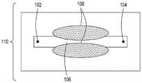
图1A是本公开的FTEP设备的一个方面的顶视图的图示。图1B是图1A所示的设备的该方面的横截面的顶视图的图示。图1C是图1A和图1B所示的设备的该方面的横截面的侧视图的图示。1A is an illustration of a top view of one aspect of the FTEP apparatus of the present disclosure. FIG. 1B is an illustration of a top view of a cross-section of this aspect of the apparatus shown in FIG. 1A . 1C is an illustration of a side view of a cross-section of this aspect of the apparatus shown in FIGS. 1A and 1B .
图2A是本公开的FTEP设备的另一方面的顶视图的图示。图2B是图2A所示的设备的该方面的横截面的顶视图的图示。图2C是图2A和图2B所示的设备的该方面的横截面的侧视图的图示。2A is an illustration of a top view of another aspect of the FTEP apparatus of the present disclosure. 2B is an illustration of a top view of a cross-section of this aspect of the apparatus shown in FIG. 2A. Figure 2C is an illustration of a side view of a cross-section of this aspect of the apparatus shown in Figures 2A and 2B.
图3A是本公开的FTEP设备的又一方面的顶视图的图示。图3B是图3A所示的设备的该方面的横截面的顶视图的图示。图3C是图3A和图3B所示的设备的该方面的横截面的侧视图的图示。3A is an illustration of a top view of yet another aspect of the FTEP apparatus of the present disclosure. 3B is an illustration of a top view of a cross-section of this aspect of the apparatus shown in FIG. 3A. Figure 3C is an illustration of a side view of a cross-section of this aspect of the apparatus shown in Figures 3A and 3B.
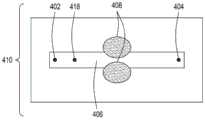
图4A是具有用于细胞和外源性物质的单独入口的本文描述的FTEP设备的另一方面的横截面的顶视图的图示。图4B是图4A所示的设备的该方面的横截面的顶视图的图示。图4C是图4C所示的设备的该方面的横截面的侧视图的图示。图4D是对图4D所示的设备的该方面的变形的横截面的侧视图的图示。图4E是对图4C和图4D所示的设备的该方面的另一变形的横截面的侧视图的图示。4A is an illustration of a top view of a cross-section of another aspect of the FTEP device described herein with separate inlets for cells and exogenous substances. 4B is an illustration of a top view of a cross-section of this aspect of the apparatus shown in FIG. 4A. Figure 4C is an illustration of a side view of a cross-section of this aspect of the apparatus shown in Figure 4C. Figure 4D is an illustration of a side view of a cross-section of a variation of this aspect of the device shown in Figure 4D. 4E is an illustration of a cross-sectional side view of another variation of this aspect of the apparatus shown in FIGS. 4C and 4D.
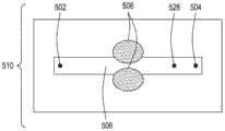
图5A是本公开的FTEP设备的又一方面的横截面的顶视图的图示,其中FTEP包括用于细胞和外源性物质的两个单独入口。图5B是图5A所示的设备的该方面的横截面的侧视图的图示。图5C是图5A和图5B所示的设备的该方面的横截面的侧视图的图示。5A is an illustration of a top view of a cross-section of yet another aspect of the FTEP device of the present disclosure, wherein the FTEP includes two separate inlets for cells and exogenous substances. 5B is an illustration of a side view of a cross-section of this aspect of the apparatus shown in FIG. 5A. Figure 5C is an illustration of a side view of a cross-section of this aspect of the apparatus shown in Figures 5A and 5B.
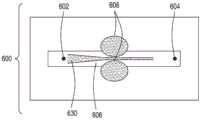
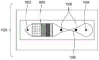
图6是本公开的FTEP设备的又一额外方面的横截面的顶视图的图示,在这里包括来自输入通道的流体的流动聚焦。6 is an illustration of a top view of a cross-section of yet another additional aspect of the FTEP apparatus of the present disclosure, here including flow focusing of fluid from an input channel.
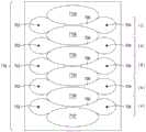
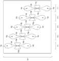
图7A是本公开的FTEP设备的第一多路复用方面的横截面的顶视图的图示。图7B是本公开的设备的第二多路复用方面的横截面的顶视图的图示。图7C是本公开的设备的第三多路复用方面的横截面的顶视图的图示。图7D是本公开的设备的第四多路复用方面的横截面的顶视图的图示。图7E是本公开的设备的第五多路复用方面的横截面的顶视图的图示。7A is an illustration of a top view of a cross-section of a first multiplexing aspect of a FTEP device of the present disclosure. 7B is an illustration of a top view of a cross-section of a second multiplexing aspect of the apparatus of the present disclosure. 7C is an illustration of a top view of a cross-section of a third multiplexing aspect of the apparatus of the present disclosure. 7D is an illustration of a top view of a cross-section of a fourth multiplexing aspect of the apparatus of the present disclosure. 7E is an illustration of a top view of a cross-section of a fifth multiplexing aspect of the apparatus of the present disclosure.
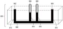
图8A是本公开的FTEP设备的又一方面的顶视图的图示。图8B是图8A所示的设备的该方面的横截面的顶视图的图示。图8C是图8A和图8B所示的设备的该方面的横截面的侧视图的图示。图8D是图8A、图8B和图8C所示的设备的该方面的下半部分的横截面的侧视图的图示。图8E是图8A-8D所示的设备的该方面的变形的横截面的侧视图的图示,其中在这里电极位于FTEP设备的底部上。8A is an illustration of a top view of yet another aspect of the FTEP apparatus of the present disclosure. 8B is an illustration of a top view of a cross-section of this aspect of the apparatus shown in FIG. 8A. Figure 8C is an illustration of a side view of a cross-section of this aspect of the apparatus shown in Figures 8A and 8B. 8D is an illustration of a side view of a cross-section of the lower half of the aspect of the apparatus shown in FIGS. 8A, 8B, and 8C. Figure 8E is an illustration of a side view of a cross-section of a variation of this aspect of the device shown in Figures 8A-8D, where electrodes are here on the bottom of the FTEP device.
图9A是本公开的FTEP设备的又一方面的顶视图的图示。图9B是图9A所示的设备的该方面的横截面的顶视图的图示。图9C是图9A和图9B所示的设备的该方面的横截面的侧视图的图示。9A is an illustration of a top view of yet another aspect of the FTEP apparatus of the present disclosure. 9B is an illustration of a top view of a cross-section of this aspect of the apparatus shown in FIG. 9A. 9C is an illustration of a side view of a cross-section of this aspect of the apparatus shown in FIGS. 9A and 9B.
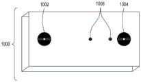
图10A是本公开的FTEP设备的替代方面的顶视图的图示。图10B是图10A所示的设备的该方面的横截面的顶视图的图示。图10C是图10A和图10B所示的设备的该方面的变形的横截面的顶视图的图示。图10D是图10A-10C所示的设备的该方面的横截面的侧视图的图示。图10E是图10A-10D所示的设备的该方面的下半部分的横截面的侧视图的图示。10A is an illustration of a top view of an alternate aspect of the FTEP apparatus of the present disclosure. 10B is an illustration of a top view of a cross-section of this aspect of the apparatus shown in FIG. 10A. 10C is an illustration of a top view of a cross-section of a variation of this aspect of the apparatus shown in FIGS. 10A and 10B . 10D is an illustration of a side view of a cross-section of this aspect of the apparatus shown in FIGS. 10A-10C. Figure 10E is an illustration of a side view of a cross-section of the lower half of the aspect of the apparatus shown in Figures 10A-10D.
图11A是本公开的FTEP设备的又一方面的顶视图的图示。图11B是图11A所示的设备的该方面的横截面的顶视图的图示。图11C是图11A-11B所示的本公开的设备的该方面的横截面的侧视图的图示。图11D是对图11A-11B所示的设备的该方面的变形的横截面的侧视图的图示。图11E是对图11A-11B所示的设备的方面的变形的横截面的侧视图的图示。11A is an illustration of a top view of yet another aspect of the FTEP apparatus of the present disclosure. 11B is an illustration of a top view of a cross-section of this aspect of the apparatus shown in FIG. 11A. 11C is an illustration of a side view of a cross-section of this aspect of the apparatus of the present disclosure shown in FIGS. 11A-11B . 11D is an illustration of a side view of a cross-section of a variation of this aspect of the apparatus shown in FIGS. 11A-11B . 11E is an illustration of a side view of a cross-section of a variation of the aspect of the apparatus shown in FIGS. 11A-11B .
图12A是本公开的FTEP设备的又一方面的横截面的顶视图的图示。图12B是图12A所示的设备的该方面的横截面的顶视图的图示。图12C是图12A和图12B所示的设备的该方面的横截面的侧视图的图示。12A is an illustration of a top view of a cross-section of yet another aspect of the FTEP apparatus of the present disclosure. Figure 12B is an illustration of a top view of a cross-section of this aspect of the apparatus shown in Figure 12A. Figure 12C is an illustration of a side view of a cross-section of this aspect of the apparatus shown in Figures 12A and 12B.
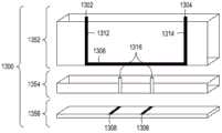
图13A是本公开的FTEP设备的另一方面的横截面的侧视图的图示。图13B是图13A所示的设备的该方面的横截面的顶视图的图示。13A is an illustration of a cross-sectional side view of another aspect of the FTEP apparatus of the present disclosure. 13B is an illustration of a top view of a cross-section of this aspect of the apparatus shown in FIG. 13A.
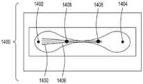
图14是具有流动聚焦特征的FTEP设备的一个方面的横截面的顶视图的图示。14 is an illustration of a top view of a cross-section of an aspect of a FTEP device with flow focusing features.
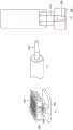
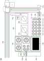
图15A至15C分别是流通式电穿孔设备的顶透视图、底透视图和底视图,流通式电穿孔设备可以是独立FTEP模块的一部分或者作为在自动化多模块细胞处理系统中的一个模块。图15D示出了在图15C中描绘的FTEP单元的扫描电子显微照片。图15E示出了在图15B和图15C中被描绘为黑条的过滤器1570和1572的扫描电子显微照片。图15F描绘(i)在插入到FTEP设备内之前的电极;(ii)电极;以及(iii)插入到电极通道内的电极,该电极和电极通道相邻于流动通道。图15G示出了开孔的两种不同配置的两个扫描电子显微照片,其中电极通道与流动通道交会。Figures 15A to 15C are top, bottom, and bottom views, respectively, of a flow-through electroporation apparatus that may be part of a stand-alone FTEP module or as a module in an automated multi-module cell processing system. Figure 15D shows a scanning electron micrograph of the FTEP cell depicted in Figure 15C. Figure 15E shows scanning electron micrographs of
图16A和图16B描绘了组合试剂盒和电穿孔设备的替代实施例。Figures 16A and 16B depict an alternate embodiment of a combination kit and electroporation device.
图17描绘了包括FTEP设备和附加可选模块的示例性自动化多模块细胞处理系统。Figure 17 depicts an exemplary automated multi-module cell processing system including a FTEP device and additional optional modules.
图18是用于使用包括在转化模块中的FTEP的自动化多模块细胞处理系统的方法的实施例的框图。18 is a block diagram of an embodiment of a method for an automated multi-module cell processing system using FTEP included in a transformation module.
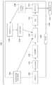
图19是示例性自动化多模块细胞处理系统的简化框图,其中可以使用本文描述的FTEP设备中的一个或更多个。19 is a simplified block diagram of an exemplary automated multi-module cell processing system in which one or more of the FTEP devices described herein may be used.
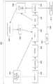
图20是示例性自动化多模块细胞处理系统的不同实施例的简化框图,其中可以使用本文描述的FTEP设备中的一个或更多个。20 is a simplified block diagram of various embodiments of an exemplary automated multi-module cell processing system in which one or more of the FTEP devices described herein may be used.
图21是示例性自动化多模块细胞处理系统的又一实施例的简化框图,其中可以使用本文描述的FTEP设备中的一个或更多个。21 is a simplified block diagram of yet another embodiment of an exemplary automated multi-module cell processing system in which one or more of the FTEP devices described herein may be used.
图22是示例性自动化多模块细胞处理系统的实施例的简化框图,其中可以使用本文描述的FTEP设备中的一个或更多个。22 is a simplified block diagram of an embodiment of an exemplary automated multi-module cell processing system in which one or more of the FTEP devices described herein may be used.
图23是示例性自动化多模块细胞处理系统的实施例的简化框图,其中可以使用本文描述的FTEP设备中的一个或更多个。23 is a simplified block diagram of an embodiment of an exemplary automated multi-module cell processing system in which one or more of the FTEP devices described herein may be used.
图24是展示穿过本公开的FTEP设备的流动通道的在缓冲液中的细胞和外源性物质的层流的照片。24 is a photograph showing the laminar flow of cells and exogenous material in buffer through the flow channel of the FTEP device of the present disclosure.
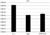
图25A是示出使用本公开的设备和比较器电穿孔设备对大肠杆菌进行的电穿孔的结果的柱状图。图25B是示出如本文所述以比较器电穿孔设备作为基准的通过FTEP转化的大肠杆菌细胞的摄取、切割和编辑效率的柱状图。25A is a bar graph showing the results of electroporation of E. coli using the device of the present disclosure and a comparator electroporation device. Figure 25B is a bar graph showing the uptake, cleavage and editing efficiencies of E. coli cells transformed by FTEP as described herein using a comparator electroporation device as a benchmark.
图26是示出使用本公开的FTEP设备和比较器电穿孔方法对酿酒酵母进行的电穿孔的结果的柱状图。26 is a bar graph showing the results of electroporation of Saccharomyces cerevisiae using the FTEP device of the present disclosure and the comparator electroporation method.
图27示出了FTEP流量和压力相对于过去的时间的关系曲线图(顶部)以及压力系统和FTEP的简单描述(底部)。Figure 27 shows a graph of FTEP flow and pressure versus elapsed time (top) and a brief description of the pressure system and FTEP (bottom).
应当理解,附图不一定是按比例的,以及相似的参考数字指相似的特征。It should be understood that the drawings are not necessarily to scale and that like reference numerals refer to like features.
详细描述Detailed Description
结合一个实施例描述的所有功能被规定为可适用于本文描述的附加实施例,除非其中被明确规定或者其中特征或功能与附加实施例不兼容。例如,在给定的特征或功能结合一个实施例被明确描述但没有结合替代实施例被明确提及的情况下,应当理解,该特征或功能可以结合替代实施例被部署、利用或实现,除非该特征或功能与替代实施例不兼容。All functions described in connection with one embodiment are intended to be applicable to additional embodiments described herein, unless explicitly stated therein or in which the feature or function is incompatible with the additional embodiment. For example, where a given feature or function is expressly described in connection with one embodiment but not explicitly mentioned in connection with alternative embodiments, it should be understood that the feature or function can be deployed, utilized or implemented in conjunction with alternative embodiments, unless This feature or function is not compatible with alternative embodiments.
除非另外指示,本文描述的技术的实践可以采用在本领域中实践的技术人员的技能内的分子生物学(包含重组技术)、细胞生物学、生物化学和基因工程技术的常规技术和描述。这样的常规技术和描述可以在标准实验室手册中被找到,例如Green和Sambrook的Molecular Cloning:ALaboratory Manual,第4版,Cold Spring Harbor LaboratoryPress,冷泉港(Cold Spring Harbor),N.Y.,(2014);Ausubel等人eds.的CurrentProtocols in Molecular Biology(2017);Neumann等人的Electroporation andElectrofusion in Cell Biology,Plenum Press,纽约,1989;以及Chang等人的Guide toElectroporation and Electrofusion,Academic Press,加利佛尼亚(1992),所有这些文献为了所有目的通过引用被全部并入本文。Unless otherwise indicated, the practice of the techniques described herein may employ conventional techniques and descriptions of molecular biology (including recombinant techniques), cell biology, biochemistry and genetic engineering techniques that are within the skill of those skilled in the art. Such routine techniques and descriptions can be found in standard laboratory manuals, such as Green and Sambrook's Molecular Cloning: A Laboratory Manual, 4th Edition, Cold Spring Harbor Laboratory Press, Cold Spring Harbor, N.Y., (2014); Ausubel et al. eds. Current Protocols in Molecular Biology (2017); Neumann et al. Electroporation and Electrofusion in Cell Biology, Plenum Press, New York, 1989; and Chang et al., Guide to Electroporation and Electrofusion, Academic Press, California ( 1992), all of which are hereby incorporated by reference in their entirety for all purposes.
注意,如在本文和在所附的权利要求中使用的,单数形式“一(a)”、“一(an)”和“该(the)”包括复数所指对象,除非上下文另外清楚地规定。因此,例如对“寡核苷酸”的提及指提供相同功能的一种或更多种寡核苷酸,并且对“方法”的提及包括对本领域中的技术人员已知的等效步骤和方法的提及,等等。也就是说,除非另有明确规定,如本文使用的,词“一(a)”、“一(an)”和“该(the)”具有“一个或更多个”的含义。此外,应当理解,可以在本文使用的术语例如“左”、“右”、“顶”、“底”、“前”、“后”、“侧”、“高度”、“长度”、“宽度”、“上”、“下”、“内部”、“外部”、“内”、“外”仅描述参考点,且并不一定将本公开的实施例限制到任何特定的定向或配置。此外,术语例如“第一”、“第二”、“第三”等仅仅标识如本文公开的多个部分、部件、步骤、操作、功能和/或参考点中的一个,并且同样不一定将本公开的实施例限制到任何特定的配置或定向。Note that, as used herein and in the appended claims, the singular forms "a (a)," "an (an)," and "the (the)" include plural referents unless the context clearly dictates otherwise. . Thus, for example, reference to an "oligonucleotide" refers to one or more oligonucleotides that provide the same function, and reference to a "method" includes equivalent steps known to those skilled in the art and method mentions, etc. That is, as used herein, the words "a (a)," "an (an)," and "the (the)" have the meaning of "one or more," unless expressly stated otherwise. In addition, it should be understood that terms such as "left", "right", "top", "bottom", "front", "rear", "side", "height", "length", "width" may be used herein. "," "upper," "lower," "inner," "outer," "inner," and "outer" describe points of reference only, and do not necessarily limit embodiments of the present disclosure to any particular orientation or configuration. Furthermore, terms such as "first," "second," "third," etc. merely identify one of a number of parts, components, steps, operations, functions, and/or points of reference as disclosed herein, and likewise do not necessarily Embodiments of the present disclosure are limited to any particular configuration or orientation.
此外,术语“大约”、“近似”、“较小”和类似术语通常指包括在20%、10%或优选地在某些实施例中5%内的裕度内的所识别的值以及在其间的任何值的范围。Furthermore, the terms "about", "approximately", "less than" and similar terms generally refer to the identified value included within a margin of 20%, 10%, or preferably within 5% in some embodiments and within Any range of values in between.
除非另外规定,本文使用的所有技术和科学术语具有与本发明所属的领域内的普通技术人员通常理解的相同的含义。在本文提到的所有的出版物为了所有目的(包括描述和公开可以结合目前描述的发明使用的设备、构想和方法的目的)通过引用被并入。Unless otherwise defined, all technical and scientific terms used herein have the same meaning as commonly understood by one of ordinary skill in the art to which this invention belongs. All publications mentioned herein are incorporated by reference for all purposes, including the purpose of describing and disclosing devices, concepts, and methods that may be used in connection with the presently described invention.
当值的范围被提供时,应该理解,在那个范围的上限和下限之间的每一个中间值和在那个规定的范围中的任何其他规定值或中间值被包括在本发明内。这些较小的范围的上限和下限可以独立地被包括在较小的范围内,且也被包括在本发明内,受制于在规定的范围中的任何特别排除的限制。在规定的范围包括限制中的一个或两个时,排除那些所包括的限制中的任一个或两个的范围也被包括在本发明内。When a range of values is provided, it should be understood that every intervening value between the upper and lower limit of that range and any other stated or intervening value in that stated range is encompassed within the invention. The upper and lower limits of these smaller ranges may independently be included in the smaller ranges, and are also encompassed within the invention, subject to any specifically excluded limit in the stated range. Where the stated range includes one or both of the limitations, ranges excluding either or both of those included limitations are also included in the invention.
在下面的描述中,阐述许多具体细节以提供本发明的更彻底的理解。然而,对本领域中的技术人员将明显,可以在没有这些具体细节中的一个或更多个的情况下实践本发明。在其他实例中,没有描述本领域中的技术人员已知的特征和过程,以避免使本发明含混不清。本文使用的术语意欲具有如本领域中的技术人员所理解的平常且普通的含义。In the following description, numerous specific details are set forth in order to provide a more thorough understanding of the present invention. However, it will be apparent to one skilled in the art that the present invention may be practiced without one or more of these specific details. In other instances, features and procedures known to those skilled in the art have not been described in order to avoid obscuring the present invention. Terms used herein are intended to have their plain and ordinary meanings as understood by those skilled in the art.
发明综述Invention overview
电穿孔是一种用于细胞膜的透化的广泛使用的方法,其通过用电刺激在细胞膜上暂时生成孔来工作。电穿孔的应用包括DNA、RNA、siRNA、肽、蛋白质、抗体、药物或其他物质到各种细胞(例如,哺乳动物细胞(包括人类细胞)、植物细胞、古生菌、酵母、其他真核细胞、细菌和其他细胞类型的输送。此外,细胞类型的混合物也可以在单次运行中被电穿孔;例如大肠杆菌菌株的混合物、细菌菌株的混合物、酵母菌株的混合物、哺乳动物细胞的混合物。电刺激也可用于在杂交瘤或其他融合细胞的产生中的细胞融合。在典型的电穿孔过程期间,细胞悬浮在有利于细胞存活的缓冲液或培养基中。对于细菌细胞电穿孔,低电导培养基(例如,水、甘油溶液和诸如此类)常常用于减少由瞬时高电流引起的热产生。然后将细胞和待电穿孔到细胞中的物质(共同地称为“细胞样品”)放置在嵌有两个扁平电极的试管中用于放电。例如,Bio-Rad(加州Hercules)建造产品的GENE PULSER XCELLTM线以使在试管中的细胞电穿孔。传统上,电穿孔需要高场强。Electroporation is a widely used method for permeabilization of cell membranes, which works by temporarily creating pores in the cell membrane with electrical stimulation. Applications of electroporation include DNA, RNA, siRNA, peptides, proteins, antibodies, drugs or other substances into various cells (eg, mammalian cells (including human cells), plant cells, archaea, yeast, other eukaryotic cells , bacteria and other cell types. Additionally, mixtures of cell types can also be electroporated in a single run; e.g. mixtures of E. coli strains, mixtures of bacterial strains, mixtures of yeast strains, mixtures of mammalian cells. Electroporation Stimulation can also be used for cell fusion in the production of hybridomas or other fused cells. During a typical electroporation process, cells are suspended in a buffer or medium that favors cell survival. For bacterial cell electroporation, low-conductance cultures Bases (eg, water, glycerol solutions, and the like) are often used to reduce heat generation caused by transient high currents. The cells and the substance to be electroporated into the cells (collectively referred to as "cell samples") are then placed on the embedded Two flat electrodes are used in a test tube for discharge. For example, Bio-Rad (Hercules, Calif.) builds the GENE PULSER XCELL™ line of products to electroporate cells in the test tube. Traditionally, electroporation requires high field strengths.
一般来说,使用小于约20ml和低至1μl的细胞悬液体积的微流控电穿孔允许对转染或转化过程的更精确的控制,并且与实验室规模的电穿孔设备相比允许与其他细胞处理工具的灵活集成。因此,微流控电穿孔为例如单细胞转化、处理和分析、多单元FTEP设备配置以及综合的自动化多模块细胞处理和分析提供了独特的优点。In general, the use of microfluidic electroporation with cell suspension volumes of less than about 20 ml and as low as 1 μl allows more precise control of the transfection or transformation process and allows comparison with other laboratory-scale electroporation devices Flexible integration of cell processing tools. Thus, microfluidic electroporation offers unique advantages for, for example, single-cell transformation, processing and analysis, multi-unit FTEP device configuration, and comprehensive automated multi-module cell processing and analysis.
本公开提供了实现具有低毒性的高效细胞电穿孔的电穿孔设备、电穿孔系统和方法,其中电穿孔设备和系统可以与其他自动化细胞处理工具集成。此外,本公开的电穿孔设备允许多路复用,其中两个到许多个电穿孔单元被构造和并行地使用,这允许与机器人液体操纵仪器的特别容易的集成。这种自动化仪器包括但不限于来自Tecan(瑞士Mannedorf)、Hamilton(内华达州Reno)、Beckman Coulter(科罗拉多州Fort Collins)等的现成自动化液体操纵系统。The present disclosure provides electroporation devices, electroporation systems, and methods that enable high-efficiency cell electroporation with low toxicity, wherein the electroporation devices and systems can be integrated with other automated cell processing tools. Furthermore, the electroporation apparatus of the present disclosure allows for multiplexing, wherein two to many electroporation units are constructed and used in parallel, which allows for particularly easy integration with robotic liquid handling instruments. Such automated instruments include, but are not limited to, off-the-shelf automated liquid handling systems from Tecan (Mannedorf, Switzerland), Hamilton (Reno, NV), Beckman Coulter (Fort Collins, CO), and the like.
在电穿孔过程期间,重要的是使用足以实现物质到细胞内的电穿孔的电压,但不是太大的电压,因为太大的功率将降低细胞生存力。例如,为了使人类细胞系的悬液电穿孔,在来自大约1000μF的电容器的指数放电的情况下对于在4mm间隙试管中的0.2ml样品需要200伏。然而,如果将相同的0.2ml细胞悬液放置在具有2cm电极距离(试管间隙距离的5倍)的较长容器中,所需的电压将为1000伏,但仅仅需要40μF的电容器(1000μF的1/25),因为来自电容器的电能遵循以下方程式:During the electroporation process, it is important to use a voltage that is sufficient to effect electroporation of the substance into the cells, but not too high, as too much power will reduce cell viability. For example, to electroporate a suspension of a human cell line, 200 volts is required for a 0.2 ml sample in a 4 mm gap tube with exponential discharge from a capacitor of approximately 1000 μF. However, if the same 0.2 ml of cell suspension were placed in a longer vessel with a 2 cm electrode distance (5 times the tube gap distance), the required voltage would be 1000 volts, but only a 40 μF capacitor (1000 μF of 1 /25), because the power from the capacitor follows the equation:
E=0.5U2CE=0.5U2 C
其中,E是电能,U是电压以及C是电容。因此,高压脉冲发生器易于制造,因为它需要小得多的电容器来存储相似量的能量。类似地,生成更高电压的其他波形也不是困难的。where E is electrical energy, U is voltage and C is capacitance. Therefore, a high-voltage pulse generator is easy to manufacture because it requires a much smaller capacitor to store a similar amount of energy. Similarly, other waveforms of higher voltages are not difficult to generate.
本发明的电穿孔设备可以允许在相对短的时间量内的细胞转化的高速率。细胞转化的速率取决于细胞类型和被转化的细胞的数量。例如,对于大肠杆菌,电穿孔设备可提供每分钟103到1012、每分钟104到1010、每分钟105到109、每分钟106到108个细胞的细胞转化率。通常,每分钟可转化108个酵母细胞,以及每分钟可转化1010-1011个细菌细胞。电穿孔设备还允许使用平行设备在单个转化过程中转化范围从1个细胞到1011个细胞的成批细胞。The electroporation device of the present invention can allow a high rate of cellular transformation in a relatively short amount of time. The rate of cell transformation depends on the cell type and the number of cells transformed. For example, for E. coli, the electroporation device can provide cell transformation rates of103 to1012 per minute,104 to1010 per minute,105 to109 per minute,106 to108 cells per minute. Typically,108 yeast cells can be transformed per minute, and1010-1011bacterial cells can be transformed per minute. The electroporation device also allows for the transformation of batches of cells ranging from 1 cell to 1011 cells in a single transformation process using parallel devices.
示例性FTEP实施例Exemplary FTEP Embodiment
本文描述的本发明的第一方面在图1A-1C中示出。图1A示出了具有入口102和出口104的FTEP设备100的平面顶视图,入口102用于将包含细胞和待输送到细胞中的外源性物质的流体引入到FTEP设备100内,以及出口104用于在电穿孔之后移除转化的细胞。椭圆形电极108被定位成限定流动通道(未示出)的中心部分,其中通道基于电极的曲率而变窄。图1B示出了从设备100的顶部看的剖视图110,其中入口102、出口104和电极108相对于流动通道106被定位。注意,电极108限定流动通道106的变窄。图1C示出具有入口102和入口通道112以及出口104和出口通道114的设备100的侧剖视图120。电极108是椭圆形的,并且被定位成使得它们限定流动通道106的狭窄部分。A first aspect of the invention described herein is illustrated in Figures 1A-1C. Figure 1A shows a top plan view of a
在本公开的FTEP设备中,转化的毒性水平导致在电穿孔之后的大于30%的活细胞,优选地在转化之后的大于35%、40%、45%、50%、55%、60%、70%、75%、80%、85%、90%、95%或甚至99%的活细胞,这取决于细胞类型和被引入到细胞内的核酸。In the FTEP device of the present disclosure, the level of toxicity of transformation results in greater than 30% viable cells after electroporation, preferably greater than 35%, 40%, 45%, 50%, 55%, 60%, 70%, 75%, 80%, 85%, 90%, 95% or even 99% of living cells, depending on the cell type and the nucleic acids introduced into the cells.
FTEP设备的壳体可以根据FTEP设备是否将被重新使用、进行高压灭菌的或是用后即可丢弃的而由许多材料制成,包括不锈钢、硅、玻璃、树脂、聚氯乙烯、聚乙烯、聚酰胺、聚苯乙烯、聚乙烯、聚丙烯、丙烯腈丁二烯、聚碳酸酯、聚醚醚酮(PEEK)、聚砜和聚氨酯、这些和其它聚合物的共聚物。类似地,在设备中的通道的壁可以由任何合适的材料制成,包括硅树脂、树脂、玻璃、玻璃纤维、聚氯乙烯、聚乙烯、聚酰胺、聚乙烯、聚丙烯、丙烯腈丁二烯、聚碳酸酯、聚醚醚酮(PEEK)、聚砜和聚氨酯、这些和其它聚合物的共聚物。优选的材料包括结晶苯乙烯、环烯烃聚合物(COP)和环烯烃共聚物(COC),其允许设备完全通过注射成型在一个零件中形成,除电极和例如底部密封膜(如果存在的话)之外(见例如图16B(v))。The housing of the FTEP device can be made from a number of materials, including stainless steel, silicon, glass, resin, polyvinyl chloride, polyethylene, depending on whether the FTEP device will be reused, autoclaved, or disposable , polyamide, polystyrene, polyethylene, polypropylene, acrylonitrile butadiene, polycarbonate, polyetheretherketone (PEEK), polysulfone and polyurethane, copolymers of these and other polymers. Similarly, the walls of the channels in the device can be made of any suitable material, including silicone, resin, glass, fiberglass, polyvinyl chloride, polyethylene, polyamide, polyethylene, polypropylene, acrylonitrile butadiene alkene, polycarbonate, polyetheretherketone (PEEK), polysulfone and polyurethane, copolymers of these and other polymers. Preferred materials include crystalline styrene, cyclic olefin polymers (COP), and cyclic olefin copolymers (COC), which allow the device to be formed entirely in one part by injection molding, except for electrodes and, for example, a bottom seal film (if present) outside (see, eg, Figure 16B(v)).
本文描述的FTEP设备(或FTEP设备的部分)可以通过各种技术例如作为整个设备或者通过被融合或以其他方式耦合的结构层的创建来被创建或制造。例如,对于金属FTEP设备,制造可以包括精密机械加工或激光加工;对于硅FTEP设备,制造可以包括干法或湿法蚀刻;对于玻璃FTEP设备,制造可以包括干法或湿法蚀刻、喷粉、喷沙或光结构化;以及对于塑料FTEP设备,制造可以包括热成型、注射成型、热压印或激光加工。FTEP设备的部件可以单独地被制造,且然后被组装,或者FTEP设备的某些部件(或者甚至除电极之外的整个FTEP设备)可以被制造(例如,使用3D印刷)或者成型(例如,使用注射成型)为单个实体,其他部件在成型之后被添加。例如,壳体和通道可以被制造或成型为单个实体,电极稍后被添加以形成FTEP单元(见例如图16F)。在一些实施例中,如图16B(v)所示,膜或平坦基底可用于密封设备的底部。在一些实施例中,膜由与FTEP设备相同的材料(在这种情况下,例如结晶苯乙烯、环烯烃聚合物(COP)或环烯烃共聚物(COC))制成。FTEP设备也可以在两个或更多个平行层(例如,具有水平通道和过滤器的层、具有垂直通道的层以及具有入口和出口端口的层)中形成,这些层被单独地制造和/或成型并在制造之后被组装(见例如图13A)。The FTEP devices (or portions of FTEP devices) described herein may be created or fabricated by various techniques, eg, as a whole device or by the creation of structural layers that are fused or otherwise coupled. For example, for metal FTEP devices, fabrication may include precision machining or laser processing; for silicon FTEP devices, fabrication may include dry or wet etching; for glass FTEP devices, fabrication may include dry or wet etching, powder spraying, Sandblasting or photostructuring; and for plastic FTEP devices, fabrication can include thermoforming, injection molding, hot embossing, or laser machining. Components of the FTEP device may be fabricated individually and then assembled, or certain components of the FTEP device (or even the entire FTEP device except the electrodes) may be fabricated (eg, using 3D printing) or formed (eg, using injection molding) as a single entity, other parts are added after molding. For example, the housing and channel can be fabricated or shaped as a single entity, with electrodes added later to form the FTEP unit (see eg, Figure 16F). In some embodiments, as shown in Figure 16B(v), a film or flat substrate can be used to seal the bottom of the device. In some embodiments, the membrane is made of the same material as the FTEP device (in this case, eg, crystalline styrene, cyclic olefin polymer (COP), or cyclic olefin copolymer (COC)). FTEP devices can also be formed in two or more parallel layers (eg, a layer with horizontal channels and filters, a layer with vertical channels, and a layer with inlet and outlet ports) that are fabricated separately and/or or formed and assembled after manufacture (see eg Figure 13A).
在特定的方面中,可以使用电路板作为底座来制造FTEP设备,其中电极、过滤器和/或流动通道在期望的配置中在电路板上形成,并且设备的剩余壳体包含例如一个或更多个入口和出口通道和/或流动通道被形成为单独层,该单独层然后被密封到电路板上。壳体的顶部到电路板上的密封提供本公开的FTEP设备的不同元件的期望配置。此外,两个到许多个FTEP设备(多达48个或更多个)可以在单个基底上并行地被制造,然后与彼此分离或并行地被使用。在某些实施例中,FTEP设备是可重新使用的,并且在一些实施例中,FTEP设备是用后即可丢弃的。在额外的实施例中,FTEP设备可以是耐高压灭菌的。In certain aspects, a FTEP device may be fabricated using a circuit board as a base, with electrodes, filters, and/or flow channels formed on the circuit board in a desired configuration, and the remaining housing of the device containing, for example, one or more The inlet and outlet channels and/or flow channels are formed as a single layer, which is then sealed to the circuit board. The sealing of the top of the housing to the circuit board provides the desired configuration of the different elements of the FTEP device of the present disclosure. Furthermore, two to many FTEP devices (up to 48 or more) can be fabricated in parallel on a single substrate and then used separately from each other or in parallel. In some embodiments, the FTEP device is reusable, and in some embodiments, the FTEP device is disposable. In additional embodiments, the FTEP device may be autoclavable.
电极108可以由任何合适的金属(例如,铜、不锈钢、钛、铝、黄铜、银、铑、金或铂)或石墨形成。一种优选的电极材料是合金303(UNS330300)奥氏体不锈钢。外加电场可能破坏由金属如铝制成的电极。如果多次使用(例如,非用后即可丢弃的)流通式FTEP设备是需要的,与用后即可丢弃的一次性流通式FTEP设备相反,电极板可以被涂覆有抗电化学腐蚀的金属。导电涂层如贵金属(例如金)可以用来保护电极板。
此外,FTEP设备可以包括推挽式气动装置以允许多遍(multi-pass)电穿孔过程;也就是说,待电穿孔的细胞可以从入口被“拉”向出口用于一遍电穿孔,然后从流通式FTEP设备的出口端被“推”向入口端以再次在电极之间通过用于另一遍电穿孔。这个过程可以重复一到许多次。Additionally, the FTEP apparatus can include push-pull pneumatics to allow for a multi-pass electroporation process; that is, cells to be electroporated can be "pulled" from the inlet to the outlet for one pass of electroporation, and then from the The outlet end of the flow-through FTEP device is "pushed" towards the inlet end to pass again between the electrodes for another pass of electroporation. This process can be repeated one to many times.
根据待电穿孔的细胞的类型(例如,细菌、酵母、哺乳动物)和电极的配置,在流动通道中的电极之间的距离可以广泛地改变。例如,在图1A-1C、图2A-2C、图3A-3C、图4A-4E、图5A-5C、图6和图7A-7E所示的实施例中,其中电极形成流动通道壁的一部分,其中流动通道在宽度上减小,在流动通道中的电极之间的距离可以在10μm和5mm之间,或者在25μm和3mm之间,或者在50μm和2mm之间,或者在75μm和1mm之间。在例如在图8A-8E、图9A-9C、图10A-10E、图11A-11E、图12A-12C、图13A-13B、图14和图16A-16D所示的其他实施例中,其中电极位于通道变窄的两端上,在流动通道中的电极之间的距离可以在1mm和10mm之间,或者在2mm和8mm之间,或者在3mm和7mm之间,或者在4mm和6mm之间。FTEP设备的总尺寸可以是在长度上从3cm到15cm,或者在长度上4cm到12cm,或者在长度上4.5cm到10cm。FTEP设备的总宽度可以从0.5cm到5cm,或者从0.75cm到3cm,或者从1cm到2.5cm,或者从1cm到1.5cm。Depending on the type of cells to be electroporated (eg, bacteria, yeast, mammals) and the configuration of the electrodes, the distance between electrodes in a flow channel can vary widely. For example, in the embodiments shown in Figures 1A-1C, Figures 2A-2C, Figures 3A-3C, Figures 4A-4E, Figures 5A-5C, Figures 6, and Figures 7A-7E, where the electrodes form part of the walls of the flow channel , where the flow channel decreases in width, the distance between electrodes in the flow channel may be between 10 μm and 5 mm, or between 25 μm and 3 mm, or between 50 μm and 2 mm, or between 75 μm and 1 mm between. In other embodiments such as shown in FIGS. 8A-8E, 9A-9C, 10A-10E, 11A-11E, 12A-12C, 13A-13B, 14, and 16A-16D, the electrodes On both ends of the channel narrowing, the distance between the electrodes in the flow channel may be between 1mm and 10mm, or between 2mm and 8mm, or between 3mm and 7mm, or between 4mm and 6mm . The overall dimensions of the FTEP device may be from 3 cm to 15 cm in length, or 4 cm to 12 cm in length, or 4.5 cm to 10 cm in length. The overall width of the FTEP device can be from 0.5 cm to 5 cm, or from 0.75 cm to 3 cm, or from 1 cm to 2.5 cm, or from 1 cm to 1.5 cm.
变窄的流动通道的区域通常足够宽,使得至少两个细胞可以并排配合在狭窄部分中。例如,典型的细菌细胞在直径上为1μm;因此,用于转化这种细菌细胞的FTEP设备的流动通道的狭窄部分将为至少2μm宽。在另一个例子中,如果哺乳动物细胞在直径上为约50μm,用于转化这种哺乳动物细胞的FTEP设备的流动通道的狭窄部分将为至少100μm宽。也就是说,FTEP设备的狭窄部分将不在物理上扭曲或“挤压”被转化的细胞。The area of the narrowed flow channel is generally wide enough that at least two cells can fit side by side in the narrow section. For example, a typical bacterial cell is 1 μm in diameter; therefore, the narrow portion of the flow channel of a FTEP device used to transform such bacterial cells will be at least 2 μm wide. In another example, if mammalian cells are about 50 μm in diameter, the narrow portion of the flow channel of the FTEP device used to transform such mammalian cells will be at least 100 μm wide. That is, the narrow sections of the FTEP device will not physically twist or "squeeze" the transformed cells.
在其中储器用于将细胞和外源性物质引入到FTEP设备内的FTEP设备的实施例中,储器在体积上范围从100μl到10mL,或从500μl到75mL,或从1mL到5mL。在FTEP中的流速范围从每分钟0.1mL至5mL,或从每分钟0.5mL至3mL,或从每分钟1.0mL至2.5mL。在FTEP设备中的压力范围从1到30psi,或从2到10psi,或从3到5psi。In embodiments of the FTEP device in which the reservoir is used to introduce cells and exogenous material into the FTEP device, the reservoir ranges in volume from 100 μl to 10 mL, or from 500 μl to 75 mL, or from 1 mL to 5 mL. Flow rates in FTEP ranged from 0.1 to 5 mL per minute, or from 0.5 to 3 mL per minute, or from 1.0 to 2.5 mL per minute. Pressures in FTEP equipment range from 1 to 30 psi, or from 2 to 10 psi, or from 3 to 5 psi.
为了避免在电极之间的不同场强,电极应该平行地被布置。此外,电极的表面应尽可能光滑而没有针孔或峰。具有1至10μm的粗糙度Rz的电极是优选的。在本发明的另一个实施例中,流通式电穿孔设备包括将地电位施加到FTEP设备的至少一个附加电极。In order to avoid different field strengths between the electrodes, the electrodes should be arranged in parallel. Furthermore, the surface of the electrode should be as smooth as possible without pinholes or peaks. Electrodes having a roughness Rz of 1 to 10 μm are preferred. In another embodiment of the invention, the flow-through electroporation device includes at least one additional electrode that applies ground potential to the FTEP device.
电极被配置为输送1-25Kv/cm或5-20Kv/cm或10-20Kv/cm。电极间隔开越远,越多的电压就需要被提供;此外,所输送的电压当然取决于被穿孔的细胞的类型、细胞被悬浮于的培养基、电穿孔通道的大小以及电极的长度和直径。存在可以对FTEP设备采用的许多不同的脉冲形式,包括指数衰减波、方波或矩形波、任意波形或波形的选定组合。一种类型的常见脉冲形式是通常通过使加载电容器放电到细胞样品而产生的指数衰减波。通过将电感器链接到细胞样品使得初始峰值电流可以被衰减,可以使指数衰减波较不陡峭。当在指定序列中的多个波形被使用时,它们可以在同一方向(直流电)或不同的方向(交流电)上。使用交流电可能是有益的,因为细胞的两个局部表面而不是仅仅一个表面可以用于分子输运,且交流电可以防止电解。脉冲发生器可以由数字或模拟面板控制。在一些实施例中,方波形式是优选的,并且在其他实施例中,在方波之前的初始波尖峰是优选的。The electrodes were configured to deliver 1-25 Kv/cm or 5-20 Kv/cm or 10-20 Kv/cm. The farther the electrodes are spaced apart, the more voltage needs to be supplied; furthermore, the voltage delivered will of course depend on the type of cells being perforated, the medium in which the cells are suspended, the size of the electroporation channel, and the length and diameter of the electrodes . There are many different pulse forms that can be applied to the FTEP device, including exponentially decaying waves, square or rectangular waves, arbitrary waveforms, or selected combinations of waveforms. One type of common pulse form is an exponentially decaying wave, usually produced by discharging a loading capacitor to the cellular sample. By linking the inductor to the cell sample so that the initial peak current can be attenuated, the exponential decay wave can be made less steep. When multiple waveforms in a given sequence are used, they can be in the same direction (DC) or different directions (AC). The use of alternating current may be beneficial because two localized surfaces of the cell instead of just one surface can be used for molecular transport, and alternating current can prevent electrolysis. The pulse generator can be controlled from a digital or analog panel. In some embodiments, a square wave form is preferred, and in other embodiments, an initial wave peak preceding the square wave is preferred.
FTEP设备可被配置为使在1μl至5ml、10μl至2ml、25μl至1ml或50μl至750μl之间的细胞样品体积电穿孔。用于使细胞和被电穿孔到细胞内的物质(试剂)悬浮以用于电穿孔过程的培养基或缓冲液可以是针对被转化或转染的细胞的类型的任何合适的培养基或缓冲液,例如SOC、MEM、DMEM、IMDM、RPMI、Hanks'、PBS和Ringer's溶液,其中培养基可以作为成套材料的一部分在试剂盒中被提供。此外,因为细胞必须在转化或转染之前成为电转感受态的,所以缓冲液也可以包括甘油或山梨醇,且也可以包括表面活性剂。对于大多数真核细胞的电穿孔,培养基或缓冲液通常包含盐以维持适当的渗透压力。在培养基或缓冲液中的盐也使培养基变成导电的。对于非常小的原核细胞(例如细菌)的电穿孔,有时使用水或10%甘油作为低电导培养基以允许非常高的电场强度。在这种情况下,待输送的带电分子仍然使水基培养基变得比脂基细胞膜更导电,并且该培养基仍然可以被粗略地考虑为导电的,特别是与细胞膜相比。The FTEP device can be configured to electroporate cell sample volumes between 1 μl to 5 ml, 10 μl to 2 ml, 25 μl to 1 ml, or 50 μl to 750 μl. The medium or buffer used to suspend the cells and the substances (reagents) electroporated into the cells for the electroporation process can be any suitable medium or buffer for the type of cells being transformed or transfected , such as SOC, MEM, DMEM, IMDM, RPMI, Hanks', PBS, and Ringer's solution, wherein the medium can be provided in the kit as part of a kit. In addition, because the cells must be electrocompetent prior to transformation or transfection, the buffer may also include glycerol or sorbitol, and may also include surfactants. For electroporation of most eukaryotic cells, the medium or buffer usually contains salts to maintain proper osmotic pressure. Salts in the medium or buffer also make the medium conductive. For electroporation of very small prokaryotic cells (eg bacteria) water or 10% glycerol is sometimes used as a low conductance medium to allow very high electric field strengths. In this case, the charged molecules to be transported still make the water-based medium more conductive than lipid-based cell membranes, and the medium can still be roughly considered conductive, especially compared to cell membranes.
待电穿孔到细胞中的化合物可以是在本领域中已知对电穿孔有用的任何化合物,例如核酸、寡核苷酸、多核苷酸、DNA、RNA、肽、蛋白质和小分子,如激素、细胞因子、趋化因子、药物或药物前体。The compound to be electroporated into a cell can be any compound known in the art to be useful for electroporation, such as nucleic acids, oligonucleotides, polynucleotides, DNA, RNA, peptides, proteins, and small molecules such as hormones, Cytokines, chemokines, drugs or prodrugs.
本文描述的FTEP设备的第二方面在图2A-2C中示出。图2A示出了具有用于将包含细胞和外源性物质的流体引入到FTEP设备200内的入口202和用于在电穿孔之后移除转化的细胞的出口204的FTEP设备200的顶部平面图。圆柱形电极208被定位成限定流动通道(未示出)的中心部分,其中流动通道作为电极的曲率的结果而变窄。图2B示出了从FTEP设备200的顶部看的剖视图210,其中入口202、出口204和电极208相对于流动通道206被定位。再次注意,电极208限定流动通道206的狭窄部分或区域。图2C示出了具有入口202和入口通道212以及出口204和出口通道214的设备200的侧剖视图220。电极208是圆柱形的,并且位于流动通道206中,限定流动通道206的狭窄部分。A second aspect of the FTEP apparatus described herein is illustrated in Figures 2A-2C. 2A shows a top plan view of the
本公开的FTEP设备的第三方面在图3A-3C中示出。图3A示出了具有用于将包含细胞和外源性物质的流体引入到FTEP设备300内的入口302和用于在电穿孔之后移除转化的细胞的出口304的FTEP设备300的顶部平面图。半圆柱形电极308定位成限定流动通道(未示出)的狭窄部分,其中通道基于电极的曲率从两端变窄。图3B示出了从设备300的顶部看的剖视图310,其中入口302、出口304和电极308相对于流动通道306被定位。图3C示出了具有入口302和入口通道312以及出口304和出口通道314的设备300的侧剖视图320。半圆柱形电极308位于流动通道306中,使得它们限定流动通道306的狭窄部分。应该注意,在图1A-1C、图2A-2C和图3A-3C中描绘的设备示出实质上位于沿着流动通道的中路的电极;然而,在该设备的其他方面中,电极可以定位在流动通道的更朝着设备的入口或更朝着设备的出口的狭窄区域中。A third aspect of the FTEP apparatus of the present disclosure is shown in Figures 3A-3C. 3A shows a top plan view of the
图4A-4E示出了具有用于细胞和外源性物质的单独入口的本公开的FTEP设备的多个方面。图4A示出了FTEP设备400的顶部平面图,FTEP设备400具有:用于将包含细胞的流体引入到FTEP设备400内的第一入口402;用于将包含待电穿孔到细胞内的外源性物质的流体引入到FTEP设备400内的第二入口418;电极408;以及用于在电穿孔之后移除转化的细胞的出口404。尽管这些方面用圆柱形电极示出,如图4A所示,但具有弯曲边缘的其它形状(例如,如关于图1A-1C和图3A-3C所示的椭圆形、半圆柱形和诸如此类)的电极可以用于限定流动通道,如在本文更详细描述的。图4B示出了从设备400的顶部看的剖视图410,其中第一入口402、第二入口418、出口404和电极408相对于流动通道406被定位。4A-4E illustrate aspects of the FTEP device of the present disclosure with separate inlets for cells and xenobiotics. 4A shows a top plan view of a
图4C示出了FTEP设备400的该方面的第一侧剖视图420,其中第一入口402和第二入口418如图4A和图4B所示被定位。在图4C中,第一入口通道412和第二入口通道422独立地与流动通道406交会,并且液体(细胞和待穿孔或输送到细胞的物质)通过流动通道406流到出口通道414和出口404,其中转化的细胞从FTEP设备被移除。电极408位于流动通道406中,使得它们限定流动通道406的狭窄部分。图4D示出了对在图4C中描绘的FTEP设备400的方面的变形的侧剖视图430。在这里,第一入口通道412和第二入口通道424在三通接头处与流动通道406相交,并且液体(细胞和待穿孔或输送到细胞的物质)通过流动通道406流到出口通道414和出口404,其中转化的细胞从FTEP设备被移除。电极408位于流动通道406中,限定流动通道406的狭窄部分。图4E示出了图4A和图4B所示的FTEP设备400的又一变形的第一侧剖视图440。在这里,第一入口402和第二入口418在交叉点426处相交,其中在将组合流体引入到流动通道406之前,细胞和外源性物质混合。流体通过流动通道406流到出口通道414和出口404,其中转化的细胞从FTEP设备被移除。电极408位于流动通道406中,使得它们限定流动通道406的狭窄部分。Figure 4C shows a first side
图5A-5C示出了具有用于细胞和外源性物质的单独入口的本公开的FTEP设备的另一个方面。图5A示出了电穿孔设备500的顶部平面图,该电穿孔设备500具有用于引入包含细胞的流体的第一入口502、用于引入待电穿孔到细胞内的外源性物质的第二出口518以及用于在电穿孔之后移除转化的细胞的出口504。电极508位于第一入口502和第二入口528之间,在第一入口502处细胞被引入到FTEP设备内,以及在第二入口528处外源性物质被引入到FTEP设备内。图5B示出了从FTEP设备500的顶部看的剖视图510,其中第一入口502、第二入口528、出口504和电极508位于第一入口通道502和第二入口通道528之间,其中电极508形成流动通道506的狭窄部分。图5C示出了具有第一入口502和第一入口通道512、第二入口528和第二入口通道532以及出口通道514和出口504的FTEP设备500的侧剖视图520,在第一入口502处细胞被引入到FTEP设备内,在第二入口528处外源性物质被引入到FTEP设备内,以及在出口504处转化的细胞从出口504和设备被移除。电极508位于流动通道506中限定流动通道506的狭窄部分,并且位于第一入口通道512和第二入口通道532之间,使得待引入到细胞内的物质在细胞被电穿孔之后被添加到包括细胞的流体。5A-5C illustrate another aspect of the FTEP device of the present disclosure with separate inlets for cells and exogenous substances. Figure 5A shows a top plan view of an
图6示出了FTEP设备,其中从输入通道引入到流动通道内的流体的流例如使用不互溶流体(例如油或空气流)被聚焦,以在包含细胞和外源性物质的流体流经过电极时使它变窄。图6示出了从FTEP设备600的顶部看的剖视图,其中第一入口602、第二入口630、出口604和电极608位于第一入口通道602和出口604之间。使用不互溶流体产生流动聚焦,其中电极608形成流动通道606的狭窄部分。(例如,见例如Kumacheva的美国公开号2010/0184928)。Figure 6 shows a FTEP device in which the flow of fluid introduced into the flow channel from the input channel is focused, for example using an immiscible fluid (eg, oil or air flow), to pass the electrode in the flow of fluid containing cells and exogenous species make it narrower. FIG. 6 shows a cross-sectional view from the top of the
示例性FTEP设备的多路复用方面在图7A-7E中示出。图7A示出了本公开的FTEP设备的第一多路复用方面的横截面的顶视图。图7A中的FTEP设备是多路复用FTEP设备700,其中对于每个FTEP单元的平行流动通道706部分地由形成设备(i)、(ii)、(iii)、(iv)和(v)的共享圆柱形电极708a-708f限定。每个流动通道706具有用于将不同组的细胞和/或外源性物质引入到FTEP单元内的入口702和用于从FTEP单元移除转化的细胞的出口704。相邻单元共享电极,其中电极使电荷交替,例如+/-/+/-/+(也就是说,如果电极708a是+,电极708b是-,电极708c是+,电极708d是-,以此类推)。图7B是本公开的FTEP设备710的第二多路复用方面的横截面的顶视图的图示。这是多路复用设备710,其中平行流动通道706部分地由共享椭圆形电极708a-708f限定。每个流动通道706具有用于将不同组的细胞和/或外源性物质引入到流动通道706内的入口702以及用于从FTEP单元(i)、(ii)、(iii)、(iv)和(v)移除转化的细胞的出口。再次,相邻的设备共享电极,其中电极使电荷交替,例如+/-/+/-/+。Multiplexing aspects of an exemplary FTEP device are shown in Figures 7A-7E. 7A shows a top view of a cross-section of a first multiplexing aspect of the FTEP device of the present disclosure. The FTEP apparatus in Figure 7A is a multiplexed
图7C是本公开的FTEP设备的第三多路复用方面的横截面的顶视图的图示。在该示例性多路复用FTEP设备720中,单独的FTEP单元是交错的。平行流动通道706部分地由未被共享的单独圆柱形电极714a-714j限定,如图7A和7B所示。每个流动通道706具有它自己的电极对708、用于将不同组的细胞和/或外源性物质引入到FTEP设备内的入口702以及用于从FTEP单元(i)、(ii)、(iii)、(iv)和(v)移除转化的细胞的出口。图7D是另一示例性多路复用FTEP设备的横截面的顶视图的图示。在该多路复用FTEP设备730中,交错的平行流动通道706部分地由单独椭圆形电极716a-716j限定。每个流动通道706具有它自己的非共享电极对716(例如,716a/716b、716c/716d、716e/716f、716g/716h和716i/716j)、用于将不同组的细胞和/或外源性物质引入到FTEP单元内的入口702和用于从FTEP单元移除转化的细胞的出口704。图7E是另一示例性多路复用FTEP设备的横截面的顶视图的图示。在该示例性多路复用设备740中,交错的平行流动通道706部分地由单独半圆柱形电极716a-716j限定。每个流动通道706具有它自己的电极对716、用于将不同组的细胞和/或外源性物质引入到FTEP单元内的单独入口702以及用于从FTEP单元移除转化的细胞的出口704。7C is an illustration of a top view of a cross-section of a third multiplexing aspect of the FTEP apparatus of the present disclosure. In this exemplary multiplexed
本公开的FTEP设备的其他方面在图8A-8E中示出。注意,在图8A-8E中(和在图9-14中)的FTEP设备中,电极不位于流动通道的任一侧上以使流动通道变窄;替代地,电极被放置成使得第一电极放置在入口和流动通道的狭窄区域之间,以及第二电极放置在流动通道的狭窄区域和出口之间。图8A示出了具有用于将包含细胞和外源性物质的流体引入到FTEP设备800内的入口802和用于在电穿孔之后从FTEP移除转化的细胞的出口804的FTEP设备800的顶部平面图。电极808通过设备中的通道(未示出)被引入。图8B示出了从设备800的顶部看的剖视图810,其中入口802、出口804和电极808相对于流动通道806被定位。图8C示出了具有入口802和入口通道812以及出口804和出口通道814的设备800的侧剖视图820。电极808位于电极通道816中,使得它们与流动通道806流体连通,但不直接在细胞行进通过流动通道806的路径中。再次注意,第一电极放置在入口和流动通道的狭窄区域之间,以及第二电极放置在流动通道的狭窄区域和出口之间。Additional aspects of the FTEP apparatus of the present disclosure are shown in Figures 8A-8E. Note that in the FTEP devices of FIGS. 8A-8E (and in FIGS. 9-14 ), the electrodes are not located on either side of the flow channel to narrow the flow channel; instead, the electrodes are placed such that the first electrode A second electrode is placed between the inlet and the narrow region of the flow channel, and a second electrode is placed between the narrow region of the flow channel and the outlet. Figure 8A shows the top of the
图8D中的设备800的底部的展开侧剖视图830示出在设备830的这个第一方面中的电极808位于通常垂直于流动通道806的电极通道816中,使得包含细胞和外源性物质的流体从入口通道812通过流动通道806流到出口通道814,并且在该过程中流体流入电极通道816内以与电极808接触。在这个方面中,入口通道、出口通道和电极通道都源自设备的同一平面侧,如图8C和图8D所示。然而,在某些方面例如在图8E中所示的方面中,电极从FTEP设备的与入口和出口通道不同的平面侧被引入。在这里,在设备800的这个替代方面840中的电极808位于垂直于流动通道806的电极通道816中,使得包含细胞和外源性物质的流体从入口通道812通过流动通道806流到出口通道814。在缓冲液中的细胞和外源性物质流入电极通道816内以与两个电极808接触。在这个方面中,入口通道和出口通道源自设备的与电极和电极通道源自的不同的平面侧。The expanded side
图9A-9C示出了本公开的FTEP设备的又一方面。图9A示出了具有用于将包含细胞的流体引入到FTEP设备900内的第一入口902和用于在电穿孔之后从FTEP设备移除转化的细胞的出口904的FTEP设备900的顶部平面图。然而,在该FTEP设备中,有用于引入待电穿孔到细胞内的外源性物质的第二入口922。电极908通过用机器加工到设备中的通道(未示出)被引入。图9B示出了从FTEP设备900的顶部看的剖视图910,其中第一入口902、第二入口922、出口904和电极908相对于流动通道906被定位。图9C示出了具有入口902和入口通道912以及出口904和出口通道914的设备900的侧剖视图920。电极908位于电极通道916中,使得它们与流动通道906流体连通,但实质上不在细胞行进通过流动通道906的路径中。在FTEP设备920的这个方面中的电极908位于电极通道916中,其中电极通道916通常垂直于流动通道906,使得包含细胞的流体和包含外源性物质的流体从入口902、922通过入口通道912、924流入流动通道906内并直通地到出口通道914,并且在该过程中在培养基中的外源性物质和细胞流入电极通道916内以与电极908接触。两个电极908之一和电极通道916位于入口902和922以及入口通道912和924与流动通道906的狭窄区域(未示出)之间,以及另一个电极908和电极通道916位于流动通道906的狭窄区域(未示出)与出口通道914和出口904之间。在图9C中,入口通道、出口通道和电极通道都源自设备的同一平面侧,尽管电极(以及入口和出口)也可以被配置为源自例如图8E所示的FTEP设备的不同平面侧。9A-9C illustrate yet another aspect of the FTEP apparatus of the present disclosure. 9A shows a top plan view of the
图10A-10E示出了本公开的设备的又一方面。图10A示出了具有用于将包含细胞和外源性物质的流体引入到FTEP设备1000内的入口1002和用于在电穿孔之后从FTEP设备1000移除转化的细胞的出口1004的电穿孔设备1000的顶部平面图。电极1008通过用机器加工到设备中的通道(未示出)被引入。图10B示出了从设备1000的顶部看的剖视图1010,其示出相对于流动通道1006定位的入口1002、出口1004、实质上均匀的密度的过滤器1050和电极1008。图10C示出了从设备1000的替代配置的顶部看的剖视图1020,其中入口1002、出口1004、实质上增加的梯度密度的过滤器1050和电极1008相对于流动通道1006被定位。在图10A-E中,像图9A-9C一样,第一电极放置在入口和流动通道的狭窄区域之间,以及第二电极放置在流动通道的狭窄区域和出口之间。在一些实施例(例如在图10A-10E中描绘的实施例)中,FTEP设备包括布置在流动通道内的过滤器,其位于在入口通道之后和在第一电极通道之前的流动通道中。过滤器可以在孔隙率方面是实质上均匀的(例如,具有如在图10B中的均匀密度);可选地,过滤器可以在梯度密度方面增加,其中过滤器的靠近入口的端部是密度较小的,以及过滤器的靠近流动通道的狭窄部分的端部具有较大的梯度密度(如图10C所示)。该过滤器可由任何合适的且优选地廉价的材料(包括多孔塑料、疏水聚乙烯、棉花、玻璃纤维)制成,或者该过滤器可与FTEP设备主体成一整体并被制造为FTEP设备主体的一部分(见例如图15E)。10A-10E illustrate yet another aspect of the apparatus of the present disclosure. Figure 10A shows an electroporation device with an
图10D示出了具有入口1002和入口通道1012以及出口1004和出口通道1014的设备1000的侧剖视图1030。电极1008位于电极通道1016中,使得它们与流动通道1006流体连通,但不直接在流动通道1006中。注意,过滤器1050位于入口1002和入口通道1012以及电极1008和电极通道1016之间。图10E中的FTEP设备1000的底部的展开侧剖视图1040示出在FTEP设备1000的该方面中的电极1008位于电极通道1016中并且垂直于流动通道1006,使得包含细胞和外源性物质的流体从入口通道1012通过流动通道1006流到出口通道1014,并且在该过程中流体流入电极通道1016内以与两个电极1008接触。在图10D和图10E中,入口通道、出口通道和电极通道都源自设备的同一平面侧,尽管电极(以及入口和出口)也可以被配置为源自例如图8E所示的不同的平面侧。FIG. 10D shows a side
图11A-11E示出了本公开的FTEP设备的其他方面。图11A示出了具有用于将包含细胞的流体引入到FTEP设备内的第一入口1102和用于将包含外源性物质的流体引入到FTEP设备内的第二入口1122、位于电极通道(未示出)中的电极1108以及用于在电穿孔之后移除转化的细胞的出口1104的FTEP设备1100的顶视图。图11B示出了从包括相对于流动通道1106定位的第一入口1102、第二入口1122、出口1104、过滤器1150和电极1108的设备1100的顶部看的剖视图1110。再次注意,电极1108被定位成使得第一电极在流动通道1106中的狭窄区域的“入口端”上,而第二电极在流动通道1106中的狭窄区域的“出口端”上。图11C示出了设备1100的第五方面的第一侧剖视图1120,其中第一入口1102和第二入口1122如图11A所示被定位。第一入口通道1112和第二入口通道1124在遇到过滤器1150之前单独地与流动通道1106交会,并且液体从入口通道1112和1124通过流动通道1106(和过滤器1150)流到出口通道1114和出口1104。电极1108位于电极通道1116中,使得它们与流动通道1106流体连通,但不直接在流动通道1106中。注意,在一些实施例中,电极1108可以位于电极通道1116中,使得电极1108与流动通道1106的壁齐平(例如,见图15F(iii))。可选地,电极1108可以延伸最小距离到流动通道1106内;然而,在这么做时,电极1108不延伸到流动通道1106中到电极阻碍细胞通过流动通道的流动的程度。11A-11E illustrate other aspects of the FTEP device of the present disclosure. Figure 11A shows a
图11D示出了图11A-11C所示的FTEP设备1100的该方面的变形的侧剖视图1130,其中第一入口1102和第二入口1122如图11A所示被定位。第一入口通道1112和第二入口通道1124在与流动通道1106的三通接头处和在遇到过滤器1150之前与流动通道1106相交。液体通过流动通道1106流到出口通道1114和出口1104。电极1108位于电极通道1116中,使得它们与流动通道1106流体连通,但不直接在流动通道1106中。再次,电极1108被定位成使得第一电极在流动通道1106中的狭窄区域的“入口端”上,而第二电极在流动通道1106中的狭窄区域的“出口端”上。图11E示出了对图11A-11C所示的FTEP设备1100的该方面的又一变形的侧剖视图1140。第一入口通道1112和第二入口通道1126在与流动通道1106相交之前在交叉点处交叉到单个通道内。流体从入口1102和1122通过入口通道1112和1126流入并通过流动通道1106和过滤器1150流入电极通道1116内(使得电极1108与流动通道1106流体连通),并继续通过流动通道1106到出口通道1114,并最终到出口1104,在出口1104处转化的细胞从FTEP设备1100被移除。电极1108位于电极通道1116中,使得它们与流动通道1106流体连通,但不直接在细胞行进穿过流动通道1106的流动路径中。尽管图11C-11E中的每一个示出了源自该设备的同一平面侧的入口通道、出口通道和电极通道,但在这些方面的每一个中所有的入口、出口和电极也可以被配置成源自FTEP设备的不同平面侧。11D shows a side
图12A-12C示出了本公开的FTEP设备的另一方面。图12A示出了具有用于将包含细胞的流体引入到FTEP设备1200内的第一入口1202、用于将被穿孔到细胞内的外源性物质引入到FTEP设备1200内的第二入口1228以及用于在电穿孔之后从FTEP设备1200移除转化的细胞的出口1204的电穿孔设备1200的顶视图。电极1208通过用机器加工到设备中的通道(未示出)被引入,并位于第一入口1202和第二入口1228之间。图12B示出了从设备1200的顶部看的剖视图1210,其中第一入口1202、第二入口1228、出口1204和电极1208相对于流动通道1206被定位。此外,在图12B中描绘的FTEP设备包括布置在第一入口1202和第一电极1208之间并且在流动通道1206的狭窄区域之前的过滤器。该实施例中的过滤器1250具有从大到小的孔尺寸的梯度。图12C示出了包括第一入口1202和第一入口通道1212、过滤器1250、第二入口1228和第二入口通道1232以及出口1204和出口通道1214的FTEP设备1200的侧剖视图1220。电极1208位于垂直于流动通道1206以及在第一和第二入口之间的电极通道1216中。电极1208与流动通道1206流体连通,但实质上不在细胞行进穿过流动通道1206的流动路径中。外源性物质经由第二入口1228并通过第二入口通道1232被添加到FTEP设备1200,并且在细胞被电穿孔后遇到细胞。在图12C中,入口通道、出口通道和电极通道都源自设备的同一平面侧,尽管这些特征也可以被配置为源自FTEP设备1200的不同平面侧。12A-12C illustrate another aspect of the FTEP device of the present disclosure. Figure 12A shows having a
图13A和13B分别示出了本发明的又一方面的侧剖视图和顶部剖视图。图13A示出了具有顶层1352的多层设备1300,顶层1352具有入口1302和入口通道1312、流动通道1306以及出口1304和出口通道1314。电极1308在底层1356上,例如,作为条带被设置在固体基底上。中间层1354是固体基底,电极通道1316设置在其中,以及电极通道1316在这个方面中提供在底层1356的电极1308和顶层1352的流动通道1306之间的流体连通。在流体中的细胞和外源性物质经由入口1302被引入到FTEP设备1300,并流过入口通道1312并进入流动通道1306内,且然后到出口通道1314。在该过程中,流体流入电极通道1316内,使得电极1308与流动通道1306流体接触。当细胞穿过在两个电极1308之间的流动通道1306时,细胞被穿孔。图13B示出了FTEP设备1300的该方面的局部剖面1310的顶视图,其示出入口1302、出口1304、电极1308和电极通道1316相对于流动通道1306的位置。尽管电极在这里被示为条带,但它们也可以被配置为其他形状,例如圆形、圆柱形、不对称、矩形或正方形。13A and 13B show a side cross-sectional view and a top cross-sectional view, respectively, of yet another aspect of the present invention. FIG. 13A shows a
图14示出了FTEP设备,其中从输入通道引入到流动通道内的流体的流动聚焦1430例如使用不互溶流体(例如油)或使用空气而发生,以当流体遇到电极通道和电极时使包含细胞和外源性物质的流体流聚焦(变窄)。图14示出了从设备1400的顶部看的剖视图,其具有第一入口1402、在流体离开入口通道并进入流动通道1406之后的流体的流动聚焦以及位于入口1402和出口1404之间的电极1408,其中电极1408位于流动通道1406的狭窄部分的两端上。FIG. 14 shows a FTEP apparatus in which flow focusing 1430 of fluid introduced into the flow channel from the input channel occurs, for example, using an immiscible fluid (eg, oil) or using air to cause the fluid to contain the electrode channels and electrodes as it encounters the electrode channels and electrodes. The fluid flow of cells and foreign substances is focused (narrowed). Figure 14 shows a cross-sectional view from the top of the
图15A至15C分别是六个共同连接的FTEP设备1550的顶部透视图、底部透视图和底视图,这些设备可以是例如下面在图16A和16B中的试剂盒1600的一部分(即,用作在试剂盒1600中的FTEP 1606)。图15A描绘布置在单个整体地形成的注射成型的环烯烃共聚物(COC)基底1556上的六个FTEP单元1550。图15B所示的通道1506用具有50微米至1mm的厚度的COC膜(未示出)密封。COC膜可以热粘合到组件1500的基部(在图15B中最突出地显示的表面)。在图15B和15C中,共同连接的FTEP设备具有不同的通道架构和电极布置,其在各种应用中可能是有利的。例如,设备(i)、(iv)和(v)的弯曲通道利用惯性来引导流体中的细胞远离电极。电极可以在通道中偏离中心被定位以进一步增强细胞流动并降低对细胞的损害的可能性。这对于对电解效应或在电极附近的pH的局部变化特别敏感的细胞或物质是尤其重要的。如实施例(iii)和(iv)所示,电极可以至少部分地嵌入通道壁中,以便进一步减少这些效应。Figures 15A to 15C are top perspective, bottom perspective and bottom views, respectively, of six commonly connected
六个FTEP单元1550中的每一个具有限定细胞样品入口的阱1552和限定细胞样品出口的阱1554。图15B是图15A的六个共同连接的FTEP设备1550的底部透视图,其也描绘布置在单个基底1556上的六个FTEP单元1550。可以看到六个入口阱1552,对于每个流通式电穿孔单元1550有一个入口阱1552,以及可以看到一个出口阱1554。在图15B中还可以看到针对每个FTEP单元1550的入口1502、出口1504、流动通道1506和在流动通道1506中的狭窄区域的两端上的两个电极1508。过滤器1570和1572被包括在通道中以防止通道的堵塞,特别是在流动通道的狭窄区域处。图15C是图15A和15B的六个共同连接的FTEP设备1550的底视图。在图15C中描绘了布置在单个基底1556上的六个FTEP单元1550,其中每个FTEP单元1550包括入口1502、出口1504、流动通道1506和在每个FTEP单元1550中的流动通道1506中的狭窄区域的两端上的两个电极1508。一旦六个FTEP单元1550被制造,它们就可以在所描绘的划线上从彼此分离(例如,“折断开”),并且一次被使用一个,如在图16A或16B中所描绘的盒中看到的;可选地,可以在两个或更多个FTEP单元1550并行地被使用的实施例中使用FTEP单元。Each of the six
图15D示出了在图15C中描绘的FTEP单元的扫描电子显微照片,其中图15D中的单元(i)、(ii)、(iii)、(iv)、(v)和(vi)对应于图15C中的单元(i)、(ii)、(iii)、(iv)、(v)和(vi)。在图15D中,对于每个单元,电极通道1516和流动通道1506都可以被看到。每散列标记的标度为1mm,如在每个显微照片的右下角中所示的。可以看到,在该实施例中,入口开孔具有圆形边缘,其优点包括对空气滞留的抗性、层流的促进和细胞损伤的风险的降低。圆形边缘可以具有大约10、20、30、40、50、60、70、80、90、100、150、200或250微米的曲率半径。Figure 15D shows a scanning electron micrograph of the FTEP cell depicted in Figure 15C, where cells (i), (ii), (iii), (iv), (v) and (vi) in Figure 15D correspond to Elements (i), (ii), (iii), (iv), (v) and (vi) in Figure 15C. In Figure 15D, for each cell, both
图15E示出了在图15B和15C中描绘为黑条的过滤器1570和1572的扫描电子显微照片。注意,在该实施例中,过滤器1572的孔隙率朝着流动通道(未示出)从大孔(靠近入口1502)变化到小孔。在该实施例中,通道可选地但不一定变窄。如果存在第二过滤器,第二过滤器的孔隙率也可以变化。在第二过滤器在第二电极和出口通道之间的情况下,过滤器可以朝着出口通道从大孔(靠近第二电极)变化到小孔。标度信息显示在每张显微照片中。Figure 15E shows scanning electron micrographs of
在某些实施例中,过滤器提供在流体遇到流动通道的狭窄部分之前过滤包含细胞和DNA的流体的目的。过滤器因此降低了细胞或其它物质不堵塞流动通道的狭窄部分的可能性。替代地,如果存在对堵塞流动通道的狭窄部分造成威胁的颗粒物质,过滤器将捕获颗粒物质,留下细胞/DNA/流体的其余部分可以移动通过的其它孔。所描绘的结构(与通道壁整体地成型)特别是有利的,因为它降低了设备的成本和复杂性,同时也降低了过滤器本身的零件可能移动和堵塞通道或以其他方式干扰设备操作的风险。注意,在该实施例中,过滤器具有梯度孔尺寸(从靠近入口的大孔到靠近流动通道的狭窄部分的小孔);然而,在替代实施例中,孔可以是相同的尺寸或者在尺寸上不是梯度的。In certain embodiments, the filter serves the purpose of filtering the fluid containing cells and DNA before the fluid encounters the constricted portion of the flow channel. The filter thus reduces the likelihood that cells or other substances will not block the narrow parts of the flow channel. Alternatively, if there is particulate matter that threatens to block the narrow portion of the flow channel, the filter will trap the particulate matter, leaving other pores through which the rest of the cells/DNA/fluid can move. The depicted structure (formed integrally with the channel walls) is particularly advantageous because it reduces the cost and complexity of the device, as well as the potential for parts of the filter itself to move and block the channel or otherwise interfere with the operation of the device. risk. Note that in this embodiment, the filter has a gradient of pore sizes (from large pores near the inlet to small pores near the narrow portion of the flow channel); however, in alternate embodiments, the pores may be the same size or the same size is not gradient.
此外,在另外其他实施例中,流动通道可以不变窄。在这些特定的实施例中,孔本身可用于提供这种用于增强电穿孔的变窄功能,并且当流体流过通道时流动通道壁不收缩或最小程度地收缩。这些实施例可以允许控制通过该设备的细胞的流速以优化外源性物质到各种细胞类型内的引入。Furthermore, in yet other embodiments, the flow channel may not be narrowed. In these particular embodiments, the pores themselves may be used to provide this narrowing function for enhanced electroporation, with no or minimal constriction of the flow channel walls as fluid flows through the channel. These embodiments may allow control of the flow rate of cells through the device to optimize the introduction of exogenous substances into various cell types.
此外,尽管图15E中的扫描电子显微镜照片将过滤元件显示为圆形“栓”,但应该理解,过滤器元件可以是三角形、正方形、矩形、五边形、六边形、卵形、椭圆形或其他多面形状的栓。Additionally, although the scanning electron micrograph in Figure 15E shows the filter elements as circular "plugs", it should be understood that the filter elements can be triangular, square, rectangular, pentagonal, hexagonal, oval, oval or other faceted pegs.
图15F描绘了(i)在插入到具有入口储器1552和出口储器1554的FTEP设备1500(在这里,六单元FTEP设备)内之前的电极1508。在优选实施例中,设备1500在相对于图15F(i)所示反转的定向上被使用。图15F(ii)描绘了被包含在护套内并从护套突出的电极1508。图15F(iii)描绘了插入到电极通道1516中的电极1508,其中电极通道1516(和电极1508)相邻于流动通道1506。在图15F(iii)所示的实施例中,电极与流动通道的壁齐平;也就是说,电极不在流过流动通道1506的细胞/DNA/流体的路径中,然而,电极也不在电极通道1516内凹进。实际上,电极1508可以在电极通道1516内凹进,可以延伸到电极通道1516的端部,并因此与流动通道1506的壁齐平,或者电极1508可以延伸最小的距离到流动通道1506内,只要电极不妨碍细胞通过流动通道的运动。在流动通道1506中的开孔的圆形或有斜面的边缘有助于防止截留空气并减少电场的不连续性。Figure 15F depicts (i)
图15G示出了开孔(其中电极通道1516与流动通道1506交会)的两种不同配置的两个扫描电子显微照片。在图15G(i)(顶部)中,电极通道1516和流动通道1506的交叉点处的边缘包括锐边缘。相反,在图15G(ii)(底部)中,电极通道1516和流动通道1506的交叉点处的边缘包括圆形边缘。这两种配置都被测试(数据未示出),并且发现圆形边缘配置降低了空气被截留在流动通道1506和在电极通道1516中的电极(在该图中未看到)之间的可能性。事实上,FTEP设备的电极应该是“湿的”;即浸没在流体/细胞/DNA中。Figure 15G shows two scanning electron micrographs of two different configurations of apertures where
包括FTEP的自动化多模块细胞处理系统Automated multi-module cell processing system including FTEP
图16A描绘了可以在自动化多模块细胞处理系统中使用的示例性组合试剂盒和FTEP设备1600(“盒”)。盒1600包括主体1602和试剂容器或储器1604。此外,盒1600包括FTEP设备1606,FTEP设备的各方面关于图1-6和图8-15被描述(例如,在盒的该实施例中,有单个FTEP设备)。盒1600可以是用后即可丢弃的,或者盒1600可以被配置为可重新使用的。优选地,盒1600是用后即可丢弃的。盒1600可由各种合适的材料制成,包括不锈钢、铝或塑料(包括聚氯乙烯、聚乙烯、聚酰胺、聚乙烯、聚丙烯、丙烯腈丁二烯、聚碳酸酯、聚醚醚酮(PEEK)、聚甲基丙烯酸甲酯(PMMA)、聚砜和聚氨酯以及这些和其它聚合物的共聚物)。如果盒是用后即可丢弃的,优选地,它由塑料制成。优选地,用于制造盒的材料是导热的,因为在某些实施例中盒1600接触加热或冷却在试剂容器或储器1604中的试剂的热设备(未示出)。在一些实施例中,热设备是珀尔帖设备或热电冷却器。试剂容器或储器1604可以是试剂的单独管如图16A所示被插入到其中的容器、一个或更多个共同连接的管被插入到其中的容器(例如,共同连接的五个管的行插入到试剂容器中,如在图16B(iv)中所看到的),或者试剂容器可以容纳试剂而没有插入的管。此外,在试剂盒中的容器可以针对管、共同连接的管和试剂的直接填充(direct-fill)的任何组合被配置。Figure 16A depicts an exemplary combination kit and FTEP device 1600 ("cartridge") that can be used in an automated multi-module cell processing system.
在一个实施例中,试剂盒1600的试剂容器或储器1604被配置成容纳各种尺寸的管,包括例如250ml管、25ml管、10ml管、5ml管和Eppendorf或微量离心管。在又一个实施例中,所有的容器可以被配置成容纳相同尺寸的管,例如5ml管,并且储器插入件可以用于容纳在试剂储器中的更小的管。在又一个实施例中,特别是在试剂盒是用后即可丢弃的实施例中,试剂储器容纳试剂而没有插入的管。在该用后即可丢弃的实施例中,试剂盒可以是套件的一部分,其中试剂盒被预先填充有试剂,并且容器或储器用例如箔、热封丙烯酸树脂或诸如此类被密封,并递呈给消费者,其中试剂盒然后可以在自动化多模块细胞处理系统中被使用。在试剂盒中包含的试剂将根据工作流程而变化;也就是说,试剂将根据细胞在自动化多模块细胞处理系统中所经受的过程而变化。In one embodiment, the reagent containers or
此外,图16A示出了对于试剂盒和FTEP设备的实施例的附加细节,其中试剂容器或储器1604被配置成接受管1660或热隔离物1662。此外,在热隔离物1662内的是当只需要小试剂体积时是有用的小管1654,例如Eppendorf或微量离心管。热隔离物1662是导热的,确保热或冷转移到在小管中包含的试剂,例如Eppendorf管1654。如上面所讨论的,在一些实施例中,试剂盒的主体本身是导热的,并且与热设备接触以如用户所希望的加热或冷却在其中包含的试剂。在图16A中还可以看到用于密封管1660和1654的箔密封件1658。可选地,如果试剂盒是可重新使用的,试剂盒可以包括加热和冷却在其中包含的试剂的热设备,与接触热设备相反。In addition, FIG. 16A shows additional details for an embodiment of a kit and FTEP device in which a reagent container or
在图16A所示的试剂盒1600的某些实施例中,试剂盒包括光学可读代码(例如,条形码或Aztec代码)或在板载存储器元件(未示出)中存储的指令/数据,其由自动化系统的互补传感器可读取(见通过引用并入的申请)并传输到自动化系统的处理器。代码、数据、指令或脚本提供用于由自动化系统分配试剂和控制在试剂盒1600内包含的电穿孔设备的指令((或实现指令的检索)。此外,作为在自动化多模块细胞处理系统中的一个部件的试剂盒1600可以包括指定由自动化多模块细胞处理系统执行的两个、三个、四个、五个、十个或更多个过程或者甚至指定由自动化多模块细胞处理系统执行的所有过程的代码、指令或脚本。在某些实施例中,试剂盒是用后即可丢弃的,并且被预先包装有适合于执行特定细胞处理方案(例如,基因组编辑或蛋白质产生)的试剂。因为试剂盒内容物改变而自动化多模块细胞处理系统的部件可以不改变,因此与特定试剂盒相关联的脚本与所使用的试剂和所执行的细胞处理相匹配。因此,例如试剂盒可以被预先包装有用于基因组编辑的试剂和指定用于在自动化多模块细胞处理系统中执行基因组编辑的过程步骤的脚本。In certain embodiments of the
图16B描绘了组合试剂盒和电穿孔设备的替代实施例。在16B(i)处,示出了试剂盒的主体1602,以及试剂容器或储器1604,其可被配置成容纳各种尺寸的管,包括例如250ml管、25ml管、10ml管、5ml管以及Eppendorf管或微量离心管。另外,有一个凹槽1610,FTEP设备(未示出)可以放置在凹槽1610中。图16B(ii)描绘了用于试剂盒的主体1602的盖1652。图16B(iii)描绘了组装的FTEP设备的主体1602和盖1652,其中组装的FTEP设备1660放置在凹槽1610(在(i)中看到的)内。图16B(iv)示出了可以放置在试剂容器或储器1604内的共同连接的管。图16B(v)是FTEP盒1606、带有与入口和出口储器配合的密封件或垫圈(未示出)的盖1608和用于密封FTEP设备的底部的膜1610的分解图。盖和密封件形成气密密封,允许足以以上述方式驱动在FTEP设备中的流体的气压的施加。元件1610对应于上面结合图15描述的COC膜,其密封在盒1606的下侧中的通道并用作FTEP设备1600的基部或底部。Figure 16B depicts an alternate embodiment of a combination kit and electroporation device. At 16B(i), the
图17描绘了示例性自动化多模块细胞处理仪器1700,其包括示例性FTEP设备1730作为试剂盒1710的一部分,以例如执行下面描述的示例性工作流程之一以及附加的示例性工作流程。所示的是提供自动化机械运动系统(致动器)(未示出)的台架1702,自动化机械运动系统向例如自动化多模块细胞处理仪器1700的模块(包括例如空气置换移液管1732)供应XYZ轴运动控制。在一些自动化多模块细胞处理仪器中,空气置换移液器由台架移动,且各种模块和试剂盒保持静止;然而,在其他实施例中,当各种模块移动时,移液系统可以保持静止。在自动化多模块细胞处理仪器1700中还包括洗涤或试剂盒1704,其包括储器1706。洗涤或试剂盒1704可被配置成容纳大的管,例如洗涤溶液或常常在整个迭代过程中使用的溶液。在一个例子中,当两个或更多个试剂盒1710被顺序地使用和更换时,洗涤或试剂盒1704可以被配置为保持在适当的位置上。尽管试剂盒1710和洗涤或试剂盒1704在图17中被示为单独的盒,但是洗涤盒304的内容物可以合并到试剂盒1710中。17 depicts an exemplary automated multi-module
图17的示例性自动化多模块细胞处理仪器1700还包括细胞生长模块1734。在图17所示的实施例中,细胞生长模块1734包括两个细胞生长单元1718、1720以及细胞浓缩模块1722。在替代实施例中,细胞浓缩模块1722可以与细胞生长模块1734分离,例如在单独的专用模块中。还被示为图17的自动化多模块细胞处理仪器1700的一部分的是由例如空气置换移液器1732和过滤模块1724服务的筛选/选择模块1728。还看到废物储器1726和核酸组装/脱盐模块1714,其包括反应室或管容器(未示出)且还包括磁体1716以允许使用例如磁性固相可逆固定(SPRI)珠(Applied Biological Materials Inc.,Richmond,BC)来纯化核酸。下面更详细地描述试剂盒、转化模块和细胞生长模块。The exemplary automated multi-module
图18是用于使用在图17中描绘的自动化多模块细胞处理系统的方法1800的一个实施例的框图。在第一步骤中,细胞从试剂盒1810转移1801到生长瓶1818。细胞被培养1802,例如直到它们生长到期望的OD 1803为止。然后将细胞转移1804到过滤模块1822以使细胞变成电转感受态的,并将细胞样品的体积减少到适于电穿孔的体积,以及从细胞样品除去不需要的成分,例如盐。一旦细胞变成电转感受态的并悬浮在合适的体积中用于转化,细胞样品就被转移1812到试剂盒1810中的FTEP设备1830。FIG. 18 is a block diagram of one embodiment of a
当细胞被处理用于电穿孔时,自动化多模块细胞处理系统可能正在准备待电穿孔到细胞中的核酸。作为第一步骤,将包括载体的核酸样品、包括寡核苷酸的核酸样品以及酶和其他反应组分从试剂盒的试剂储器转移1806到核酸组装模块中的用后即可丢弃的管中,且核酸组装混合物(载体+寡核苷酸+酶+试剂)被培养1807。一旦用于使核酸组装反应发生的足够的时间过去,核酸组装混合物与磁珠组合1808。混合物被培养足够的时间用于使组装的载体和寡核苷酸结合到磁珠。磁体被接合1809,使得组装的载体和寡核苷酸可以被洗涤1810和洗脱1811。一旦组装的载体被洗脱1811,组装的载体被转移1812到试剂盒中的FTEP设备。组装的载体和细胞因此在FTEP设备中组合,并且FTEP设备被接合1813。When cells are being processed for electroporation, the automated multi-module cell processing system may be preparing nucleic acids to be electroporated into cells. As a first step, the nucleic acid sample including the carrier, the nucleic acid sample including oligonucleotides, and the enzymes and other reaction components are transferred 1806 from the reagent reservoir of the kit to a disposable tube in the nucleic acid assembly module , and the nucleic acid assembly mixture (vector+oligonucleotide+enzyme+reagent) was incubated 1807. Once sufficient time has elapsed for the nucleic acid assembly reaction to occur, the nucleic acid assembly mixture is combined 1808 with the magnetic beads. The mixture is incubated for sufficient time for the assembled support and oligonucleotides to bind to the magnetic beads. The magnet is engaged 1809 so that the assembled support and oligonucleotides can be washed 1810 and eluted 1811. Once the assembled carrier is eluted 1811, the assembled carrier is transferred 1812 to the FTEP device in the kit. The assembled vector and cells are thus combined in the FTEP device, and the FTEP device is engaged 1813.
在电穿孔之后,转化的细胞可选地被转移1814到第二生长瓶以例如从转化过程中恢复,被呈递以选择,或者在该特定例子中用于基因组编辑。一旦转化的细胞已经恢复、被选择(例如,通过从试剂盒添加的抗生素或其他试剂,或者通过例如温度)或者基因组编辑已经发生,细胞就可以从仪器被去除并在进一步的研究中被使用1818,或者由过滤模块抽吸1815以被洗涤以去除死细胞和/或被浓缩、变成电转感受态的并且使用通过过滤器从在洗涤或试剂盒中的试剂储器分配的洗涤溶液被洗脱1816。洗脱的细胞然后可以被收集在洗涤盒的空器皿中。空气置换移液器可以将培养基从试剂盒转移到洗脱的细胞。步骤1801-1816的全部或一些可以对基因组编辑1817的递归循环重复;可选地,可在研究1818中使用转化的细胞。Following electroporation, the transformed cells are optionally transferred 1814 to a second growth flask, eg, to recover from the transformation process, to be presented for selection, or in this particular case for genome editing. Once transformed cells have recovered, been selected (for example, by antibiotics or other reagents added from the kit, or by, for example, temperature), or genome editing has occurred, cells can be removed from the instrument and used in further studies1818 , or aspirated 1815 by the filtration module to be washed to remove dead cells and/or to be concentrated, become electrocompetent and eluted using wash solution dispensed through the filter from the reagent reservoir in the wash or
在示例性自动化多模块细胞处理系统中的试剂盒的使用Use of the Kit in an Exemplary Automated Multi-Module Cell Processing System
如上所述,FTEP设备可在独立设备中被使用或被用作在自动化多模块处理系统中的模块。在图19示出了多模块细胞处理系统的一般示例性实施例。在一些实施例中,细胞处理系统1900可以包括壳体1960、用于引入待转化或转染的细胞的容器1902和生长模块(细胞生长设备)1904。将待转化的细胞从试剂盒转移到生长模块以被培养直到细胞达到目标OD为止。一旦细胞达到目标OD,生长模块可以冷却或冷冻细胞用于稍后处理,或者将细胞转移到过滤模块1920,其中细胞变成电转感受态的并浓缩。过滤模块1920包括例如过滤器以处理细胞以使它们变成电转感受态的并浓缩电转感受态细胞。在一个例子中,将20ml细胞+生长培养基浓缩至10%甘油中的400μl细胞。一旦电转感受态细胞被浓缩,细胞就被转移到试剂盒中的电穿孔设备以用期望核酸来转化。除了用于接收细胞的容器之外,多模块细胞处理系统还包括位于试剂盒中用于储存待电穿孔到细胞中的核酸的容器1906。核酸被转移到电穿孔设备1908,电穿孔设备1908已经包含生长到特定OD的浓缩电转感受态细胞,其中核酸被引入到细胞中。在电穿孔之后,转化的细胞被转移到例如恢复模块1910中。在这里,细胞被给予从电穿孔过程恢复的机会。As mentioned above, the FTEP device can be used in a stand-alone device or as a module in an automated multi-module processing system. A general exemplary embodiment of a multi-module cell processing system is shown in FIG. 19 . In some embodiments, the
在一些实施例中,在恢复之后,细胞被转移到储存模块1912以在例如4℃下被储存或被冷冻。然后细胞可以从取回模块1914被取回,并用于进一步离线地研究。自动化多模块细胞处理系统由被配置成基于用户输入或一个或更多个脚本来操作仪器的处理器1950控制,其中一个或更多个脚本可以与试剂盒相关联。处理器1950可以控制如由一个或更多个脚本指定的系统1900的各种模块的定时、持续时间、温度和其他操作(包括例如分配试剂)。除了一个或更多个脚本之外,或者作为一个或更多个脚本的备选方案,处理器可以用用户可以从中选择的标准协议参数来被编程;可选地,用户可以手动地选择一个或所有参数。该脚本可以指定例如OD在细胞生长模块中被读取时的波长、细胞生长到的目标OD以及细胞将达到目标OD时的目标时间。处理器可以通知用户(例如,通过对智能电话或其他设备的应用)细胞已经达到目标OD,以及对用户更新关于在自动化多模块细胞处理系统中的细胞生长模块、电穿孔设备、过滤模块、恢复模块等中的细胞的过程。In some embodiments, after recovery, cells are transferred to
在图20示出了自动化多模块细胞处理系统的第二实施例。如同图19所示的实施例一样,细胞处理系统2000可以包括壳体2060、在例如试剂盒中的细胞的储器(其中细胞将被转化或转染)2002和生长模块(细胞生长设备)2004。将待转化的细胞从例如试剂盒中的储器转移到生长模块以被培养直到细胞达到目标OD为止。一旦细胞达到目标OD,生长模块就可冷却或冷冻细胞用于稍后处理或将细胞转移至过滤模块2030,其中细胞变成电转感受态的并被浓缩至对细胞转化最佳的体积,如上面关于图19所述的。一旦被浓缩,细胞然后被转移到FTEP设备2008用于转化。A second embodiment of an automated multi-module cell processing system is shown in FIG. 20 . As with the embodiment shown in FIG. 19, the
除了用于储存细胞的储器之外,试剂盒还可以包括用于储存编辑寡核苷酸的储器2016和用于储存表达载体骨架的储器2018。编辑寡核苷酸和表达载体骨架都从例如试剂盒转移到核酸组装模块2020(例如上述核酸组装模块),其中编辑寡核苷酸被插入表达载体骨架内。组装的核酸可以转移到可选的纯化模块2022中,用于脱盐和/或制备用于转化的组装的核酸所需的其他纯化程序。一旦由纯化模块2022执行的过程完成,组装的核酸也转移到试剂盒2008中的FTEP设备,试剂盒2008已经包含生长到目标OD、被过滤并变成电转感受态的细胞培养物。在FTEP设备2008中,核酸被引入到细胞内。在电穿孔之后,细胞被转移到组合的恢复和编辑模块2010中。如上所述,在一些实施例中,自动化多模块细胞处理系统2000是执行基因编辑的系统,例如RNA直接核酸酶编辑系统。例如,参见2018年6月30日提交的USSN 16/024,816;2018年6月30日提交的USSN16/024,831;2017年10月2日提交的USSN 62/566,688;以及2017年10月3日提交的USSN 62/567,698。在恢复和编辑模块2010中,细胞被允许转化后恢复(post-transformation),并且细胞表达编辑寡核苷酸,其如下所述在细胞中编辑期望的基因。In addition to reservoirs for storing cells, the kit can include
在编辑之后,细胞被转移到储存模块2012,其中细胞可以在例如4℃下被储存,直到细胞被取回用于进一步研究。多模块细胞处理系统由处理器2050控制,处理器2050被配置为基于如由一个或更多个脚本指导的用户输入或者作为用户输入或脚本的组合来操作仪器。处理器2050可以控制系统2000的各种模块的定时、持续时间、温度和操作以及试剂从例如试剂盒的分配。处理器可以用用户可以从中选择的标准协议参数被编程,用户可以手动地指定一个或更多个参数,或者与试剂盒相关联的一个或更多个脚本可以指定一个或更多个操作和/或反应参数。此外,处理器可以通知用户(例如,通过对智能电话或其他设备的应用)细胞已经达到目标OD,以及对用户更新关于在多模块系统中的各种模块中的细胞的进展。After editing, the cells are transferred to a
多模块处理系统(例如在图20中描绘的系统)的某些实施例包括核酸组装模块(例如,促进在酵母中的缺口修复的组装模块和/或执行Gibson AssemblyTM反应、聚合酶链式反应、连接链式反应、连接酶检测反应、连接、环状聚合酶延伸克隆或其他组装或克隆方法的模块)2020。核酸组装模块2020被配置为组装便于基因组编辑事件所必需的核酸。在核酸酶导向基因组编辑系统中,载体包括可操作地链接到对核酸导向核酸酶编码的多核苷酸序列的一个或更多个调节元件。因此,在这些实施例中的核酸组装模块2020被配置为组装表达核酸导向核酸酶的表达载体。核酸组装模块2020可以根据在仪器中使用的核酸组装的类型而被温度控制。例如,当核酸组装方案被利用时,模块被配置为具有达到并保持50℃的能力。如果PCR作为自动化多模块细胞处理系统的一部分被执行,则核酸组装模块被配置为在温度之间进行热循环。温度和用于维持温度的持续时间可以通过预编程的一组参数来控制(如由脚本规定或被编程到处理器中),或者由用户使用处理器来手动地控制。Certain embodiments of multi-module processing systems, such as the system depicted in Figure 20, include nucleic acid assembly modules (e.g., assembly modules that facilitate gap repair in yeast and/or perform Gibson Assembly™ reactions, polymerase chain reaction , ligation chain reaction, ligase detection reaction, ligation, circular polymerase extension cloning or modules of other assembly or cloning methods) 2020. Nucleic
如上所述,在一个实施例中,自动化多模块细胞处理系统2000是核酸酶导向基因组编辑系统。多个基于核酸酶的系统存在,用于提供在细胞内的编辑,并且每一个基于核酸酶的系统可以在下面的任一系统中被使用:如可以在图19的自动化系统1900中执行的单个编辑系统;如可以在下面描述的图21的自动化系统2100中执行的顺序编辑系统,其例如顺序地使用不同的核酸酶导向系统来在细胞中提供两个或更多个基因组编辑;和/或如可以在图21的自动化系统2100中执行的递归编辑系统,其例如利用单个核酸酶导向系统来在细胞中同时和顺序地引入两个或更多个基因组编辑。自动化核酸酶导向处理系统使用核酸酶来切割细胞的基因组,将一个或更多个编辑引入到细胞基因组的目标区域内,或两者。核酸酶导向基因组编辑机制包括锌指编辑机制(见Urnov等人的Nature Reviews Genetics,11:636-64(2010))、大范围核酸酶编辑机制(见Epinat等人,Nucleic Acids Research,31(11):2952-62(2003));以及Arnould等人,Journal of Molecular Biology,371(1):49-65(2007)),和RNA导向编辑机制(见Jinek等人,Science,337:816-21(2012);以及Mali等人,Science,339:823-26(2013))。在特定实施例中,核酸酶编辑系统是允许控制编辑的定时的诱导系统(见Campbell,Biochem J.,473(17):2573–2589(2016);以及Dow等人,NatureBiotechnology,33390-94(2015))。也就是说,当包括核酸导向核酸酶编码DNA的细胞或细胞群体在诱导分子存在的情况下时,核酸酶的表达可以出现。调节核酸酶活性的能力可以减少离靶切割并便于精确的基因组工程。As noted above, in one embodiment, the automated multi-module
在图21中示出了多模块细胞处理系统的第三实施例。该实施例描绘了对细胞群体执行递归基因编辑的示例性系统。如同图19和图20所示的实施例,细胞处理系统2100可以包括壳体2160、用于储存待转化或转染的细胞的在例如试剂盒中的储器2102和细胞生长模块(细胞生长设备)2104。将待转化的细胞从试剂盒中的储器转移到细胞生长模块以被培养直到细胞达到目标OD为止。一旦细胞达到目标OD,生长模块就可以冷却或冷冻细胞用于稍后处理,或者生长模块可以将细胞转移到过滤模块2120,其中细胞变成电转感受态的,并且细胞的体积可以显著减小。一旦细胞被浓缩到合适的体积,细胞就被转移到试剂盒中的FTEP设备2108。除了用于储存细胞的储器之外,多模块细胞处理系统包括用于储存包括编辑寡核苷酸的载体的储器2106(也就是说,在该实施例中,自动化多模块细胞处理系统不包括核酸组装模块;替代地,核酸被预先组装地提供)。组装的核酸被转移到FTEP设备2108,其已经包含生长到目标OD的细胞培养物。在FTEP设备2108中,核酸被电穿孔到细胞中。在电穿孔之后,细胞被转移到恢复模块2124中。在恢复模块2124中,转化的细胞被允许转化后恢复。A third embodiment of a multi-module cell processing system is shown in FIG. 21 . This example depicts an exemplary system for performing recursive gene editing on a population of cells. 19 and 20, the
细胞被转移到储存模块2112,其中细胞可以被储存在例如4℃下,直到细胞被取回用于进一步研究为止,或者细胞可以被转移到第二可选的生长模块2126。一旦细胞达到目标OD,第二生长模块就可冷却或冷冻细胞以用于稍后处理,或者将细胞转移至例如编辑模块2128,其中例如可诱导核酸酶和可诱导导向核酸中的一个或两个例如通过引入热或引入用于表达核酸酶和/或导向核酸的诱导分子在细胞中被激活。在编辑之后,细胞被转移到分离和过滤模块2130,其中细胞从编辑溶液分离和/或浓缩,为转移到FTEP设备2108做准备。The cells are transferred to a
在FTEP设备2108中,细胞由第二组编辑寡核苷酸(或其他类型的寡核苷酸)转化,并且该循环重复,直到细胞由期望数量的编辑寡核苷酸转化和编辑为止。如上面关于图19和图20所讨论的,多模块细胞处理系统由被配置为基于用户输入来操作仪器的处理器2150控制,或者由包括与试剂盒相关联的至少一个脚本的一个或更多个脚本控制。处理器2150可以控制各种过程的定时、持续时间和温度、试剂的分配以及系统2100的各种模块的其他操作。例如,脚本或处理器可以控制细胞、试剂、载体和编辑寡核苷酸的分配;哪些编辑寡核苷酸用于细胞编辑以及以什么顺序;在恢复和表达模块中使用的时间、温度和其他条件,OD在细胞生长模块中被读取时的波长,细胞生长到的目标OD,以及细胞将达到目标OD时的目标时间。此外,处理器可以被编程为通知用户(例如,通过应用)关于在自动化多模块细胞处理系统中的细胞的进展。In the
图22是包括用于筛选已编辑细胞的分离模块的示例性自动化多模块细胞处理系统的实施例的简化框图。细胞处理系统2200可包括壳体2260、待转化或转染的细胞的储器2202和生长模块(细胞生长设备)2204。将待转化的细胞从储器转移到生长模块以被培养直到细胞达到目标OD为止。一旦细胞达到目标OD,生长模块就可冷却或冷冻细胞用于稍后处理,或者细胞可转移至可选的过滤模块2230,其中细胞变成电转感受态的并被浓缩至对细胞转化最佳的体积。一旦被浓缩,细胞然后转移到FTEP设备2208(转化/转染)。在本文公开的自动化多模块细胞处理系统中使用的示例性电穿孔设备包括在2017年9月30日提交的USSN 62/566,374、2017年9月30日提交的USSN 62/556,375、2018年4月13日提交的USSN62/657,651和2018年4月13日提交的USSN 62/657,654中描述的电穿孔设备,所有这些专利通过引入被全部并入本文。Figure 22 is a simplified block diagram of an embodiment of an exemplary automated multi-module cell processing system including isolation modules for screening edited cells. The
除了用于储存细胞的储器之外,系统2200还可以包括用于储存编辑寡核苷酸的储器2216和用于储存表达载体骨架的储器2218。编辑寡核苷酸和表达载体骨架都从例如试剂盒中的储器转移到核酸组装模块2220,其中编辑寡核苷酸被插入到表达载体骨架内。组装的核酸可以转移到可选的纯化模块2222,用于脱盐和/或制备用于转化的组装的核酸所需的其他纯化程序。可选地,预组装的核酸(例如编辑载体)可以储存在储器2216或2218中。一旦由纯化模块2222执行的过程完成,组装的核酸就被转移到例如FTEP设备2208,该设备已经包含生长到目标OD的细胞培养物。在FTEP设备2208中,组装的核酸被引入到细胞内。在电穿孔之后,细胞被转移到组合的恢复、细胞生长和编辑模块2210中。在一些实施例中,自动化多模块细胞处理系统2200是执行基因编辑的系统,例如RNA直接核酸酶编辑系统。例如,参见2018年6月30日提交的USSN 16/024,816和16/024,831、2017年10月2日提交的USSN62/566,688以及2017年10月3日提交的USSN 62/567,698,所有这些专利通过引用被全部并入本文。在组合的恢复、细胞生长和编辑模块2210中,细胞被允许转化后恢复,并且编辑开始。In addition to reservoirs for storing cells,
在编辑之后,细胞被转移到分离模块2240,其中细胞被排列成使得每隔室平均有一个细胞。在一些实施例中,隔室可以是阱,在一些实施例中,隔室可以是液滴,并且在一些实施例中,隔室可以是区域,例如在琼脂板上从彼此隔离的或者在功能化基底上排列的细胞。一旦被分离,细胞就被允许生长并建立菌落,菌落生长至终结大小或饱和,被例如营养物或物理界限限制。一旦菌落被建立,菌落就被池化(pooled)。分离克服了来自未经编辑的细胞的生长偏差(growth bias)和由不同编辑的适应度效果产生的生长偏差。After editing, the cells are transferred to
一旦细胞菌落被池化,细胞就可被储存在例如储存模块2212中,其中细胞可在例如4℃下被保持,直到细胞被取回用于进一步研究为止。可选地,细胞可用于另一轮编辑。多模块细胞处理系统由处理器2250控制,处理器2250被配置为基于如由一个或更多个脚本指导的用户输入或者作为用户输入或脚本的组合来操作仪器。处理器2250可以控制系统2200的各种模块的定时、持续时间、温度和操作以及试剂的分配。例如,处理器2250可以在转化后冷却细胞,直到编辑被需要为止,在那个时间温度可以升高到有助于基因组编辑和细胞生长的温度。处理器可以用用户可以从中选择的标准协议参数被编程,用户可以手动地指定一个或更多个参数,或者与试剂盒相关联的一个或更多个脚本可以指定一个或更多个操作和/或反应参数。此外,处理器可以通知用户(例如,通过对智能电话或其他设备的应用)细胞已经达到目标OD,以及对用户更新关于在多模块系统中的各种模块中的细胞的进展。Once the cell colonies are pooled, the cells can be stored, eg, in
自动化多模块细胞处理系统2200是核酸酶导向基因组编辑系统,且可以在单个编辑系统中被使用。下面所述的图23的系统被配置为执行顺序编辑,例如顺序地使用不同的核酸酶导向系统来在细胞中提供两个或更多个基因组编辑;和/或递归编辑,例如利用单个核酸酶导向系统来在细胞中引入两个或更多个基因组编辑。The automated multi-module
图23示出了多模块细胞处理系统的另一个实施例。该实施例描绘了示例性系统,其1)除了筛选之外还包括编辑诱导和细胞选择,以及2)对细胞群体执行递归基因编辑。如同图22所示的实施例一样,细胞处理系统2300可以包括壳体2360、用于储存待转化或转染的细胞的储器2302和细胞生长模块(细胞生长设备)2304。将待转化的细胞从储器转移到细胞生长模块以被培养直到细胞达到目标OD为止。一旦细胞达到目标OD,生长模块就可冷却或冷冻细胞用于随后处理,或者将细胞转移至可选的过滤模块2330,其中细胞变成电转感受态的,并且细胞的体积可显著减小。一旦细胞被浓缩到合适的体积,细胞就被转移到FTEP设备2308。除了用于储存细胞的储器之外,多模块细胞处理系统还包括用于储存包括编辑寡核苷酸2352的载体的储器。组装的核酸被转移到FTEP设备2308,其已经包含生长到目标OD的细胞培养物。在FTEP设备2308中,核酸被电穿孔到细胞中。在电穿孔之后,细胞被转移到可选的恢复模块2342中,其中细胞被允许暂时转化后恢复。Figure 23 shows another embodiment of a multi-module cell processing system. This example depicts an exemplary system that 1) includes editing induction and cell selection in addition to screening, and 2) performs recursive gene editing on a population of cells. As with the embodiment shown in FIG. 22, the cell processing system 2300 may include a housing 2360, a
在恢复之后,细胞可以被转移到储存模块2312,其中细胞可以在例如4℃下被储存,直到细胞被取回用于进一步研究为止,或者细胞可以被转移到分离和生长模块2344。在分离模块2344中,细胞被排列成使得每隔室平均有一个细胞。在一些实施例中,隔室可以是阱;液滴;或者区域,例如在琼脂板上从彼此隔离的或者在例如功能化基底上排列的细胞。一旦被分离,细胞就被允许生长几倍到很多倍,并建立菌落。一旦菌落被建立,带有细胞菌落的基底就被转移到诱导模块2346,其中诱导编辑的条件(温度、诱导或抑制化学物质的添加)存在。一旦编辑被发起并被允许继续,基底就被转移到选择模块2348,其可以包括例如选择细胞的小菌落的菌落测量和挑选设备;被配置为测量在阱或液滴中的OD并基于细胞生长来收集已编辑细胞的菌落的分光光度计;或者配置成测量在阱或液滴中的其他细胞特性并基于与细胞生长相关的细胞特性来收集已编辑细胞的菌落的分光光度计。注意,分离模块和选择模块可以被链接。一旦推定编辑的细胞被选择,它们就可以受到另一轮编辑,其以经由FTEP模块2308通过在另一个编辑盒中的另一个供体核酸的转化开始。After recovery, cells can be transferred to
在FTEP设备2308中,从第一轮编辑选择的细胞由第二组编辑寡核苷酸(或其他类型的寡核苷酸)转化,并且该循环重复,直到细胞由所需数量的例如供体核酸转化和编辑为止。在图23中例示的多模块细胞处理系统由被配置为基于用户输入来操作仪器的处理器2350控制,或者由包括与试剂盒相关联的至少一个脚本的一个或更多个脚本控制。处理器2350可以控制各种过程的定时、持续时间和温度、试剂的分配以及系统2300的各种模块的其他操作。例如,脚本或处理器可以控制细胞、试剂、载体和编辑寡核苷酸的分配;哪些编辑寡核苷酸用于细胞编辑和以什么顺序;在恢复和表达模块中使用的时间、温度和其他条件,OD在细胞生长模块中被读取时的波长,细胞生长到的目标OD,以及细胞将达到目标OD时的目标时间。此外,处理器可以被编程为通知用户(例如,通过应用)关于在自动化多模块细胞处理系统中的细胞的进展。In the
例子example
下面的例子被提出以便为本领域中的技术人员提供如何制造和使用本发明的完整公开和描述,且并不意欲限制发明人认为是他们的发明的内容的范围,它们也不意欲代表或暗示下面的实验是所执行的所有实验或仅有的实验。本领域中的技术人员将认识到,可以对如在特定方面中所示的发明做出许多变化和/或修改而不偏离如广泛描述的本发明的精神或范围。因此,当前的方面在所有方面中被考虑为说明性的而非限制性的。The following examples are presented to provide those skilled in the art with a complete disclosure and description of how to make and use the present invention, and are not intended to limit the scope of what the inventors believe to be their invention, nor are they intended to represent or imply The experiments below are all or only experiments performed. Those skilled in the art will recognize that many changes and/or modifications of the invention as shown in the specific aspects may be made without departing from the spirit or scope of the invention as broadly described. Accordingly, the present aspects are considered in all respects to be illustrative rather than restrictive.
例子1:电转感受态大肠杆菌的产生和转化Example 1: Generation and transformation of electrocompetent E. coli
为了测试FTEP设备的转化,电转感受态大肠杆菌细胞被创建。为了创建起子培养物,将6ml体积的LB chlor-25(具有25μg/ml氯霉素的LB)转移到14ml培养管。大肠杆菌的25μl等分试样用于注入LB chlor-25试管。在注入之后,试管以45°角放置在被设置到250RPM和30℃的振荡培养箱中用于在12-16小时之间的过夜生长。OD600值应该在2.0和4.0之间。将250ml LB chlor-25试管的1:100培养液体积转移到四个无菌的500ml带挡板的摇瓶中,即每250ml体积摇瓶有2.5ml。将烧瓶置于被设置到250PRM和30℃的振荡培养箱中。通过每1至2小时测量OD600来监控生长。当培养物的OD600在0.5-0.6之间(大约3-4小时)时,将烧瓶从培养箱中移除。细胞在4300RPM、4℃下用离心机分离10分钟。上清液被去除,且100ml冰冷10%甘油被转移到每个样品。细胞被轻轻地再悬浮,且洗涤程序被执行三次,每次细胞再悬浮于10%甘油中。在第四次离心分离后,将细胞再悬液转移到50ml圆锥形Falcon管,并添加另外的冰冷10%甘油以使体积达到30ml。细胞再次在4300RPM、4℃下用离心机分离10分钟,上清液被去除,且细胞团块再悬浮于10ml冰冷甘油中。细胞在细胞悬液和冰冷甘油的1:100稀释液中等分。To test the transformation of the FTEP device, electrocompetent E. coli cells were created. To create starter cultures, a 6 ml volume of LB chlor-25 (LB with 25 μg/ml chloramphenicol) was transferred to a 14 ml culture tube. A 25 μl aliquot of E. coli was used for injection into LB chlor-25 tubes. After injection, the tubes were placed at a 45° angle in a shaking incubator set to 250RPM and 30°C for overnight growth between 12-16 hours. The OD600 value should be between 2.0 and 4.0. A 1:100 volume of the 250ml LB chlor-25 tube was transferred to four sterile 500ml baffled shake flasks, ie 2.5ml per 250ml volume shake flask. The flask was placed in a shaking incubator set to 250 PRM and 30°C. Growth was monitored by measuring OD600 every 1 to 2 hours. When the OD600 of the culture was between 0.5-0.6 (approximately 3-4 hours), the flask was removed from the incubator. Cells were centrifuged at 4300 RPM, 4°C for 10 minutes. The supernatant was removed and 100 ml ice-cold 10% glycerol was transferred to each sample. Cells were gently resuspended, and washing procedures were performed three times, each time cells were resuspended in 10% glycerol. After the fourth centrifugation, the cell resuspension was transferred to a 50 ml conical Falcon tube and additional ice-cold 10% glycerol was added to bring the volume to 30 ml. The cells were centrifuged again at 4300 RPM, 4°C for 10 minutes, the supernatant was removed, and the cell pellet was resuspended in 10 ml ice-cold glycerol. Cells were aliquoted in a 1:100 dilution of cell suspension and ice-cold glycerol.
使用在图15B和15C的(ii)、(iii)和(vi)以及图15D的(ii)和(vi)处所示的FTEP设备的实施例来执行比较电穿孔实验以确定电转感受态大肠杆菌的转化效率。(对于展示细胞和外源性物质通过FTEP设备的流动通道的狭窄部分的层流的扫描电子显微照片,见图24)。用压力控制系统控制流速。将具有DNA的细胞的悬液装载到FTEP入口储器中。转化的细胞直接从入口和入口通道、通过流动通道、通过出口通道流动并进入包含恢复培养基的出口。细胞被转移到包含额外恢复培养基的试管中,在30℃下被置于培养箱中以250rpm振动3小时。细胞覆在板上以确定经受电穿孔且未能吸收(take up)质粒的菌落形成单位(CFU)以及经受电穿孔并吸收质粒的CFU。板在30℃下被培养;大肠杆菌菌落在24小时之后被计数。Comparative electroporation experiments were performed using the embodiments of the FTEP device shown at (ii), (iii) and (vi) of Figures 15B and 15C and at (ii) and (vi) of Figure 15D to determine electrocompetent large intestine Bacillus transformation efficiency. (See Figure 24 for a scanning electron micrograph showing laminar flow of cells and exogenous material through a narrow section of the flow channel of the FTEP device). The flow rate is controlled with a pressure control system. The suspension of cells with DNA was loaded into the FTEP inlet reservoir. Transformed cells flow directly from the inlet and inlet channels, through the flow channel, through the outlet channel and into the outlet containing the recovery medium. Cells were transferred to tubes containing additional recovery medium and placed in an incubator at 30°C for 3 hours with shaking at 250 rpm. Cells were plated to determine colony forming units (CFU) that underwent electroporation and failed to take up the plasmid and CFU that underwent electroporation and took up the plasmid. Plates were incubated at 30°C; E. coli colonies were counted after 24 hours.
使用体外高压电穿孔仪(NEPAGENETM ELEPO21)对照2mm电穿孔试管(Bull dogBio)来对流通式电穿孔实验进行基准检验。具有DNA的细胞悬液的储备管被制备并用于用NEPAGENETM和流通式电穿孔进行边对边实验。结果在图25A中示出。在图25A中,加阴影线///的最左侧条表示细胞输入,在加阴影线\\\的条左侧的条表示经受转化的细胞的数量,加阴影线///的右侧条表示实际上被转化的细胞的数量。与NEPAGENETM电穿孔仪相比,FTEP设备显示在不同电压下电转感受态大肠杆菌细胞的等效转化。如可以看到的,转化存活率至少为90%,且在一些实施例中至少为95%、96%、97%、98%或99%。在某些实施例中,恢复率(成功地被转化和恢复的所引入的细胞的部分)至少为0.001,且优选地在0.00001和0.01之间。在图25A中,恢复率约为0.0001。Flow-through electroporation experiments were benchmarked using an in vitro high voltage electroporator (NEPAGENE™ ELEPO21) versus 2 mm electroporation tubes (Bull dogBio). Stock tubes of cell suspensions with DNA were prepared and used for edge-to-edge experiments with NEPAGENE™ and flow-through electroporation. The results are shown in Figure 25A. In Figure 25A, the leftmost bar of hatched /// represents cell input, the bar to the left of the hatched \\\ bar represents the number of cells undergoing transformation, the right of hatched /// Bars indicate the number of cells actually transformed. Compared to the NEPAGENE™ electroporator, the FTEP device showed equivalent transformation of electro-competent E. coli cells at different voltages. As can be seen, the transformation survival rate is at least 90%, and in some embodiments at least 95%, 96%, 97%, 98% or 99%. In certain embodiments, the recovery rate (the fraction of introduced cells that are successfully transformed and recovered) is at least 0.001, and preferably between 0.00001 and 0.01. In Figure 25A, the recovery rate is about 0.0001.
此外,为了转化(摄取)、切割和编辑的效率而做出NEPAGENETMELEPO21和FTEP设备的比较。在图25B中,执行三重实验,其中加阴影线///的条表示用于转化的细胞输入的数量,以及加阴影线\\\的条表示被转化(摄取)的细胞的数量、其中细胞的基因组被从转化到细胞(切割)中的载体转录和转换的核酸酶切割的细胞的数量,以及其中编辑被实现(使用从转化到细胞中的载体转录和转换的核酸酶以及使用都从转化到细胞中的载体转录的导向RNA和供体DNA序列来切割和修复)的细胞的数量。再次,可以看到FTEP显示与NEPAGENETM电穿孔仪相当的转化、切割和编辑效率。在图25B中的FTEP的恢复率大于0.001。In addition, a comparison of the NEPAGENE™ ELEPO21 and FTEP devices was made for the efficiency of transformation (uptake), cleavage and editing. In Figure 25B, a triplicate experiment was performed, where the bars with hatched /// represent the number of cell inputs used for transformation, and the bars with hatched \\\ represent the number of cells transformed (uptake), where cells The number of cells whose genome was transcribed from the vector transformed into the cell and cleaved by the transformed nuclease, and the number of cells in which editing was achieved (using both the nuclease transcribed and transformed from the vector transformed into the cell and the use of both vector-transcribed guide RNAs and donor DNA sequences into cells to cut and repair) the number of cells. Again, it can be seen that FTEP shows comparable transformation, cleavage and editing efficiencies to the NEPAGENE™ electroporator. The recovery rate of the FTEP in Figure 25B is greater than 0.001.
例子2:电转感受态酿酒酵母的产生和转化Example 2: Generation and Transformation of Electrocompetent Saccharomyces cerevisiae
为了进一步测试FTEP设备的转化,使用如在Bergkessel和Guthrie的“MethodsEnzymol”(529:311-20(2013))中综合阐述的方法来产生酿酒酵母细胞。简要地,YFAP培养基被注入用于过夜生长,3ml注入以产生100ml的细胞。所处理的每100ml的培养物产生大约1ml的感受态细胞。细胞在30℃下在振动培养箱中被注入,直到它们达到1.5+/-0.1的OD600为止。To further test the transformation of the FTEP device, Saccharomyces cerevisiae cells were generated using the method as comprehensively described in Bergkessel and Guthrie, "Methods Enzymol" (529:311-20 (2013)). Briefly, YFAP medium was injected for overnight growth and 3 ml was injected to yield 100 ml of cells. Approximately 1 ml of competent cells were produced per 100 ml of culture treated. Cells were injected in a shaking incubator at 30°C until they reached an OD600 of 1.5+/-0.1.
对于被生长并被保持在室温下的每100mL的细胞使用100mM的乙酸锂、10mM的二硫苏糖醇和50mL的缓冲液来制备调节缓冲液。在250ml瓶中在4300rpm下收获细胞3分钟,并去除上清液。细胞团块悬浮在100ml的冷1M山梨醇中,在4300rpm下旋转3分钟,并且上清液再次被去除。细胞悬浮在调节缓冲液中,然后悬液被转移到合适的烧瓶中并在200RPM和30℃下被振动30分钟。悬液被转移到50ml锥形瓶,并在4300rpm下旋转3分钟。上清液被去除,且团块再悬浮于冷的1M山梨醇中。这些步骤对于总共三个洗涤-旋转-倾析步骤重复三次。团块悬浮在山梨醇中到150+/-20的最终OD。Conditioning buffer was prepared using 100 mM lithium acetate, 10 mM dithiothreitol, and 50 mL of buffer per 100 mL of cells grown and kept at room temperature. Cells were harvested in 250 ml flasks at 4300 rpm for 3 minutes and the supernatant was removed. The cell pellet was suspended in 100 ml of cold 1 M sorbitol, spun at 4300 rpm for 3 minutes, and the supernatant was again removed. Cells were suspended in conditioning buffer, then the suspension was transferred to a suitable flask and shaken for 30 minutes at 200 RPM and 30°C. The suspension was transferred to a 50 ml Erlenmeyer flask and spun at 4300 rpm for 3 minutes. The supernatant was removed and the pellet was resuspended in cold 1M sorbitol. These steps were repeated three times for a total of three wash-spin-decantation steps. The pellet was suspended in sorbitol to a final OD of 150+/-20.
使用FTEP设备来执行比较电穿孔实验以确定电转感受态酿酒酵母的转化效率。用注射泵(Harvard装置PHD ULTRATM4400)控制流速。在安装到泵上之前,具有DNA的细胞的悬液被装载到1mL玻璃注射器(Hamilton 81320注射器,PTFE Luer Lock)内。紧接着在开始流动之前,来自函数发生器的输出被开启。经处理的细胞直接流入具有1M山梨醇和羧苄青霉素的试管中。细胞被收集,直到在NEPAGENETM中被电穿孔的相同体积被处理为止,此时流动和来自函数发生器的输出停止。在30℃和250rpm下的培养箱振动器中的3小时恢复之后,细胞覆在板上以确定经受电穿孔但未能吸收质粒的菌落形成单位(CFU)和经受电穿孔并吸收质粒的CFU。板在30℃下被培养。酵母菌落在48-76小时之后被计数。Comparative electroporation experiments were performed to determine the transformation efficiency of electrocompetent S. cerevisiae using FTEP equipment. The flow rate was controlled with a syringe pump (Harvard Apparatus PHD ULTRA™ 4400). The suspension of cells with DNA was loaded into a 1 mL glass syringe (Hamilton 81320 syringe, PTFE Luer Lock) prior to mounting on the pump. Immediately before starting the flow, the output from the function generator is turned on. Treated cells flow directly into tubes with 1 M sorbitol and carbenicillin. Cells were collected until the same volume electroporated in the NEPAGENE™ was processed, at which point flow and output from the function generator ceased. After a 3 hour recovery in an incubator shaker at 30°C and 250 rpm, cells were plated to determine colony forming units (CFU) that underwent electroporation but failed to take up plasmid and CFU that underwent electroporation and took up plasmid. Plates were incubated at 30°C. Yeast colonies were counted after 48-76 hours.
使用体外高压电穿孔仪(NEPAGENETM ELEPO21)对照2mm电穿孔试管(Bull dogBio)来对流通式电穿孔实验进行基准检验。具有DNA的细胞悬液的储备管被制备并用于用NEPAGENETM和流通式电穿孔进行边对边实验。结果在图26中示出。与NEPAGENETM方法相比,该设备显示在2.5kV电压下的电转感受态酿酒酵母的更好的转化和存活。输入是被处理的细胞的总数。Flow-through electroporation experiments were benchmarked using an in vitro high voltage electroporator (NEPAGENE™ ELEPO21) versus 2 mm electroporation tubes (Bull dogBio). Stock tubes of cell suspensions with DNA were prepared and used for edge-to-edge experiments with NEPAGENE™ and flow-through electroporation. The results are shown in FIG. 26 . Compared to the NEPAGENE™ method, this device showed better transformation and survival of electrocompetent S. cerevisiae at a voltage of 2.5 kV. Input is the total number of cells processed.
例子3:FTEP压力感测和流速Example 3: FTEP Pressure Sensing and Flow Rate
在线流量传感器测量用于指示在包含细胞和DNA的液体流过FTEP芯片之后,入口储器何时、在哪里被倒空。大约65μL的液体被装载到输入储器中,并且自动化FTEP模块被通电。看在图27的顶部处的图,可以看到,在几个短暂的启动瞬变之后,流速显示在几乎8秒(8000ms)期间的大约每分钟3标准立方厘米(SCCM)的流量,直到它跳到24SCCM为止。这个瞬变出现在运行触发结束时,这是包含细胞和DNA的液体已经通过FTEP设备被处理以及空气没有流过FTEP设备的指示。该触发可构成在空气的压力(例如在从注射泵引出的导管处)中的增加的流速或突然的波动(增加或减少)的检测。在一个优选实施例中,图27中的流量传感器检测到空气流量的增加,指示流体完全从输入储器排出。在这一点上,压力可以反转以允许多遍电穿孔过程;也就是说,对于一遍电穿孔,待电穿孔的细胞可以从入口被“拉”向出口,并且一旦入口储器被倒空,传感器就可以反转压力,其中液体和细胞/DNA从流通式FTEP设备的出口端被“推”向入口端,以对于另一遍电穿孔再次在电极之间通过。这个过程可以重复一到很多次。可选地,可以完全停止压力,并取回在出口中的转化的细胞。In-line flow sensor measurements were used to indicate when and where the inlet reservoir was emptied after the liquid containing cells and DNA had flowed through the FTEP chip. Approximately 65 μL of liquid was loaded into the input reservoir and the automated FTEP module was powered up. Looking at the graph at the top of Figure 27, it can be seen that after a few brief start-up transients, the flow rate shows a flow of approximately 3 standard cubic centimeters per minute (SCCM) over a period of almost 8 seconds (8000ms) until it Skip to 24SCCM so far. This transient occurs at the end of the run trigger, which is an indication that the liquid containing cells and DNA has been processed through the FTEP device and that air is not flowing through the FTEP device. This trigger may constitute the detection of an increased flow rate or a sudden fluctuation (increase or decrease) in the pressure of the air (eg at a catheter leading from a syringe pump). In a preferred embodiment, the flow sensor in Figure 27 detects an increase in air flow, indicating that the fluid is completely drained from the input reservoir. At this point, the pressure can be reversed to allow multiple passes of the electroporation process; that is, for one pass, the cells to be electroporated can be "pulled" from the inlet to the outlet, and once the inlet reservoir is emptied, The sensor can then reverse the pressure, where the liquid and cells/DNA are "pushed" from the outlet end to the inlet end of the flow-through FTEP device to pass between the electrodes again for another pass of electroporation. This process can be repeated one to many times. Alternatively, the pressure can be stopped completely and the transformed cells retrieved in the outlet.
多周期方法可能是特别有利的,因为它限制了细胞和外源性物质在电场中的停留时间,这又可以防止细胞损伤并提高存活率。来回过程可以重复1、2、3、4、5、6、7、8、9或10次。图27在底部处示出压力系统和FTEP的简单描绘。压力歧管通过布置在歧管或储器上的一个或更多个互补的密封件或垫圈来与向上延伸的储器配合。歧管可以采取图16B(v)所示的“盖”1608的形式。The multi-cycle approach may be particularly advantageous because it limits the residence time of cells and exogenous substances in the electric field, which in turn prevents cell damage and improves survival. The back and forth process can be repeated 1, 2, 3, 4, 5, 6, 7, 8, 9 or 10 times. Figure 27 shows a simple depiction of the pressure system and FTEP at the bottom. The pressure manifold mates with the upwardly extending reservoir by one or more complementary seals or gaskets disposed on the manifold or reservoir. The manifold may take the form of a "cover" 1608 shown in Figure 16B(v).
虽然本发明由以很多不同形式的实施例满足,如关于本发明的优选实施例详细描述的,但是应理解,本公开应被考虑为本发明的原理的示范且不意欲将本发明限制到在本文说明和描述的特定实施例。很多变化可以由本领域中的技术人员做出而不偏离本发明的精神。将通过附加的权利要求和它们的等同物来估量本发明的范围。摘要和标题不应被解释为限制本发明的范围,因为它们的目的是使适当的管理机构以及一般公众能够迅速地确定本发明的一般性质。在接下来的权利要求中,除非术语“装置”被使用,否则依据35U.S.C.§112,
Claims (30)
Applications Claiming Priority (23)
| Application Number | Priority Date | Filing Date | Title |
|---|---|---|---|
| US201762566374P | 2017-09-30 | 2017-09-30 | |
| US201762566375P | 2017-09-30 | 2017-09-30 | |
| US62/566,374 | 2017-09-30 | ||
| US62/566,375 | 2017-09-30 | ||
| US201762566688P | 2017-10-02 | 2017-10-02 | |
| US62/566,688 | 2017-10-02 | ||
| US201762567697P | 2017-10-03 | 2017-10-03 | |
| US62/567,697 | 2017-10-03 | ||
| US201862620370P | 2018-01-22 | 2018-01-22 | |
| US62/620,370 | 2018-01-22 | ||
| US201862648130P | 2018-03-26 | 2018-03-26 | |
| US62/648,130 | 2018-03-26 | ||
| US201862649731P | 2018-03-29 | 2018-03-29 | |
| US62/649,731 | 2018-03-29 | ||
| US201862657654P | 2018-04-13 | 2018-04-13 | |
| US201862657651P | 2018-04-13 | 2018-04-13 | |
| US62/657,651 | 2018-04-13 | ||
| US62/657,654 | 2018-04-13 | ||
| US201862671385P | 2018-05-14 | 2018-05-14 | |
| US62/671,385 | 2018-05-14 | ||
| US201862689068P | 2018-06-23 | 2018-06-23 | |
| US62/689,068 | 2018-06-23 | ||
| PCT/US2018/053608WO2019068022A1 (en) | 2017-09-30 | 2018-09-28 | Flow through electroporation instrumentation |
Publications (1)
| Publication Number | Publication Date |
|---|---|
| CN111372650Atrue CN111372650A (en) | 2020-07-03 |
Family
ID=65895993
Family Applications (2)
| Application Number | Title | Priority Date | Filing Date |
|---|---|---|---|
| CN201880074763.7APendingCN111372650A (en) | 2017-09-30 | 2018-09-28 | Flow-through electroporation apparatus |
| CN201880076124.4APendingCN111386334A (en) | 2017-09-30 | 2018-09-30 | Automated cell processing methods, modules, instruments, and systems including flow-through electroporation devices |
Family Applications After (1)
| Application Number | Title | Priority Date | Filing Date |
|---|---|---|---|
| CN201880076124.4APendingCN111386334A (en) | 2017-09-30 | 2018-09-30 | Automated cell processing methods, modules, instruments, and systems including flow-through electroporation devices |
Country Status (7)
| Country | Link |
|---|---|
| US (9) | US10443074B2 (en) |
| EP (2) | EP3687621A4 (en) |
| JP (2) | JP6985508B2 (en) |
| CN (2) | CN111372650A (en) |
| AU (2) | AU2018338990B2 (en) |
| CA (2) | CA3074927A1 (en) |
| WO (3) | WO2019068022A1 (en) |
Families Citing this family (38)
| Publication number | Priority date | Publication date | Assignee | Title |
|---|---|---|---|---|
| EP3164482B1 (en) | 2014-07-03 | 2024-05-22 | Massachusetts Institute of Technology | Apparatus and method for optimization of cell electroporation |
| US10976232B2 (en) | 2015-08-24 | 2021-04-13 | Gpb Scientific, Inc. | Methods and devices for multi-step cell purification and concentration |
| US11208649B2 (en) | 2015-12-07 | 2021-12-28 | Zymergen Inc. | HTP genomic engineering platform |
| US9988624B2 (en) | 2015-12-07 | 2018-06-05 | Zymergen Inc. | Microbial strain improvement by a HTP genomic engineering platform |
| EP3440186A4 (en) | 2016-04-04 | 2019-12-11 | Cytequest, Inc. | SYSTEM, DEVICE AND METHOD FOR ELECTROPORATING CELLS |
| JP6985508B2 (en)* | 2017-09-30 | 2021-12-22 | インスクリプタ, インコーポレイテッド | Flow-through electroporation equipment organization |
| WO2019194799A1 (en)* | 2018-04-04 | 2019-10-10 | Hewlett-Packard Development Company, L.P. | Microfluidic cellular membrane modification devices |
| WO2019200004A1 (en)* | 2018-04-13 | 2019-10-17 | Inscripta, Inc. | Automated cell processing instruments comprising reagent cartridges |
| EP3844263A4 (en) | 2018-08-30 | 2022-05-25 | Inscripta, Inc. | Improved detection of nuclease edited sequences in automated modules and instruments |
| US10775395B2 (en)* | 2018-10-18 | 2020-09-15 | Arctoris Limited | System and method of performing a biological experiment with adaptive cybernetic control of procedural conditions |
| US11214781B2 (en) | 2018-10-22 | 2022-01-04 | Inscripta, Inc. | Engineered enzyme |
| AU2019368215B2 (en) | 2018-10-22 | 2023-05-18 | Inscripta, Inc. | Engineered enzymes |
| US11001831B2 (en) | 2019-03-25 | 2021-05-11 | Inscripta, Inc. | Simultaneous multiplex genome editing in yeast |
| WO2020210162A1 (en)* | 2019-04-08 | 2020-10-15 | Sqz Biotechnologies Company | Cartridge for use in a system for delivery of a payload into a cell |
| US20220145331A1 (en)* | 2019-06-24 | 2022-05-12 | Hewlett-Packard Development Company, L.P. | Single cell transfection with interchangeable reagent |
| KR20220098004A (en)* | 2019-11-11 | 2022-07-08 | 프레시전 인코포레이티드 | Electroporation apparatus and method |
| US11203762B2 (en) | 2019-11-19 | 2021-12-21 | Inscripta, Inc. | Methods for increasing observed editing in bacteria |
| TWI739329B (en)* | 2020-03-04 | 2021-09-11 | 瑞基海洋生物科技股份有限公司 | Nucleic acid purification mechanism |
| KR20220152304A (en) | 2020-03-10 | 2022-11-15 | 셀라레스 코포레이션 | Cell processing systems, devices and methods |
| US20220002755A1 (en)* | 2020-07-06 | 2022-01-06 | Inscripta, Inc. | Nucleic acid watermarks to assess and improve nucleic acid-guided nuclease or nickase fusion editing |
| USD965170S1 (en) | 2020-10-23 | 2022-09-27 | Life Technologies Corporation | Electroporation device |
| CN112526144B (en)* | 2020-12-29 | 2024-07-23 | 滁州瑞谷生物技术有限公司 | Platelet aggregation rate detection method and device |
| US11884924B2 (en) | 2021-02-16 | 2024-01-30 | Inscripta, Inc. | Dual strand nucleic acid-guided nickase editing |
| US12070744B2 (en)* | 2021-04-22 | 2024-08-27 | Illumina, Inc. | Valve assemblies and related systems |
| US20240425834A1 (en) | 2021-08-24 | 2024-12-26 | Inscripta, Inc. | Genome-wide rationally-designed mutations leading to enhanced cellobiohydrolase i production in s. cerevisiae |
| WO2023064444A1 (en)* | 2021-10-13 | 2023-04-20 | CyteQuest, Inc. | Devices, methods, and systems for electroporation using controlled parameters |
| US20250034595A1 (en) | 2021-12-02 | 2025-01-30 | Inscripta, Inc. | Trackable nucleic acid-guided editing |
| EP4410945A1 (en)* | 2023-02-02 | 2024-08-07 | Cellectis S.A. | Electroporation device and method |
| CN116098058B (en)* | 2023-03-01 | 2023-09-08 | 南通大学 | Device and method for puncturing and vacuumizing to induce doubling of willow chromosomes |
| US12180453B2 (en) | 2023-03-21 | 2024-12-31 | Cellares Corporation | Systems, devices, and methods for electroporation within a cell processing system |
| US12399193B2 (en) | 2023-05-05 | 2025-08-26 | Cellares Corporation | Systems, devices, and methods for combined cell processes |
| WO2024263564A2 (en)* | 2023-06-21 | 2024-12-26 | Lonza Cologne Gmbh | Multi-chambered electroporation cartridge and methods of use |
| WO2025021702A1 (en) | 2023-07-21 | 2025-01-30 | Alia Therapeutics S.R.L. | Cas9 orthologue nuclease and uses thereof |
| WO2025041046A1 (en) | 2023-08-21 | 2025-02-27 | Cellares Corporation | Systems, devices, and methods for fluid control in a cell processing system |
| WO2025041064A2 (en) | 2023-08-21 | 2025-02-27 | Cellares Corporation | Systems, devices, and methods for automatic cell sorting |
| CN117660177B (en)* | 2023-12-11 | 2024-08-20 | 中科院南昌高新技术产业协同创新研究院 | Device and method for improving protein expression effect |
| EP4624563A1 (en)* | 2024-03-25 | 2025-10-01 | The Automation Partnership (Cambridge) Ltd. | Method for performing a bioprocess on immune or naive cell cultures |
| WO2025202216A1 (en)* | 2024-03-25 | 2025-10-02 | The Automation Partnership (Cambridge) Limited | Method for performing a bioprocess on immune or naive cells in a cell culture |
Citations (6)
| Publication number | Priority date | Publication date | Assignee | Title |
|---|---|---|---|---|
| JP2007007430A (en)* | 1995-03-10 | 2007-01-18 | Maxcyte Inc | Flow electroporation chamber and method |
| EP1766004A1 (en)* | 2004-06-12 | 2007-03-28 | Digital Bio Technology Co., Ltd. | Electroporator having an elongated hollow member |
| CN101939047A (en)* | 2008-01-17 | 2011-01-05 | 基因特朗尼克斯公司 | Variable current density single needle electroporation system and method |
| EP2459696A1 (en)* | 2009-08-02 | 2012-06-06 | Qvella Corporation | Cell concentration, capture and lysis devices and methods of use thereof |
| CN106676001A (en)* | 2016-12-29 | 2017-05-17 | 中国科学院微电子研究所 | Cell electroporation system and method based on selective continuous flow of crossed narrow channels |
| WO2017160991A1 (en)* | 2016-03-16 | 2017-09-21 | Lavieu Gregory G | Methods, systems and devices for selection and generation of genome edited clones |
Family Cites Families (143)
| Publication number | Priority date | Publication date | Assignee | Title |
|---|---|---|---|---|
| CA1293460C (en) | 1985-10-07 | 1991-12-24 | Brian Lee Sauer | Site-specific recombination of dna in yeast |
| US4833080A (en) | 1985-12-12 | 1989-05-23 | President And Fellows Of Harvard College | Regulation of eucaryotic gene expression |
| US5098843A (en)* | 1987-06-04 | 1992-03-24 | Calvin Noel M | Apparatus for the high efficiency transformation of living cells |
| US6689610B1 (en) | 1989-08-22 | 2004-02-10 | University Of Utah Research Foundation | Cells and non-human organisms containing predetermined genomic modifications and positive-negative selection methods and vectors for making same |
| US5464764A (en) | 1989-08-22 | 1995-11-07 | University Of Utah Research Foundation | Positive-negative selection methods and vectors |
| KR100236506B1 (en) | 1990-11-29 | 2000-01-15 | 퍼킨-엘머시터스인스트루먼츠 | Apparatus for polymerase chain reaction |
| WO1992015694A1 (en) | 1991-03-08 | 1992-09-17 | The Salk Institute For Biological Studies | Flp-mediated gene modification in mammalian cells, and compositions and cells useful therefor |
| US6074605A (en) | 1995-03-10 | 2000-06-13 | Entremed, Inc. | Flow electroporation chamber and method |
| US5720921A (en)* | 1995-03-10 | 1998-02-24 | Entremed, Inc. | Flow electroporation chamber and method |
| DK0937098T3 (en) | 1995-06-07 | 2002-12-02 | Invitrogen Corp | Recombinational cloning using genetically engineered recombination sites |
| US5851804A (en) | 1996-05-06 | 1998-12-22 | Apollon, Inc. | Chimeric kanamycin resistance gene |
| US6774279B2 (en) | 1997-05-30 | 2004-08-10 | Carnegie Institution Of Washington | Use of FLP recombinase in mice |
| WO1999021977A1 (en) | 1997-10-24 | 1999-05-06 | Life Technologies, Inc. | Recombinational cloning using nucleic acids having recombination sites |
| CA2759882A1 (en) | 1997-12-05 | 1999-06-17 | Europaisches Laboratorium Fur Molekularbiologie | Novel dna cloning method |
| ES2229465T3 (en)* | 1998-05-04 | 2005-04-16 | F. Hoffmann-La Roche Ag | TREMO-VARIATOR THAT HAS A COVER THAT IS AUTOMATICALLY PLACED IN POSITION. |
| US6027488A (en) | 1998-06-03 | 2000-02-22 | Genetronics, Inc. | Flow-through electroporation system for ex vivo gene therapy |
| JP2003505114A (en) | 1998-07-13 | 2003-02-12 | ジェネトロニクス、インコーポレーテッド | Gene therapy targeting the skin and muscle with a pulsed electric field |
| US6150148A (en) | 1998-10-21 | 2000-11-21 | Genetronics, Inc. | Electroporation apparatus for control of temperature during the process |
| CA2361191A1 (en) | 1999-02-03 | 2000-08-10 | The Children's Medical Center Corporation | Gene repair involving the induction of double-stranded dna cleavage at a chromosomal target site |
| SE9900530D0 (en) | 1999-02-15 | 1999-02-15 | Vincenzo Vassarotti | A device for concentrating and / or purifying macromolecules in a solution and a method for manufacturing such a device |
| US6678558B1 (en) | 1999-03-25 | 2004-01-13 | Genetronics, Inc. | Method and apparatus for reducing electroporation-mediated muscle reaction and pain response |
| US6818185B1 (en) | 1999-05-28 | 2004-11-16 | Cepheid | Cartridge for conducting a chemical reaction |
| US6300108B1 (en) | 1999-07-21 | 2001-10-09 | The Regents Of The University Of California | Controlled electroporation and mass transfer across cell membranes |
| US7420659B1 (en)* | 2000-06-02 | 2008-09-02 | Honeywell Interantional Inc. | Flow control system of a cartridge |
| JP3638503B2 (en)* | 2000-06-12 | 2005-04-13 | アークレイ株式会社 | Measuring apparatus, measuring method and recording medium using cartridge type container |
| US6916632B2 (en) | 2000-08-21 | 2005-07-12 | Invitrogen Corporation | Methods and reagents for molecular cloning |
| FR2814642B1 (en) | 2000-10-03 | 2005-07-01 | Ass Pour Le Dev De La Rech En | TRANSGENIC MOUSE FOR THE TARGETED RECOMBINATION MEDIATED BY THE MODIFIED CRE-ER |
| US7029916B2 (en) | 2001-02-21 | 2006-04-18 | Maxcyte, Inc. | Apparatus and method for flow electroporation of biological samples |
| US20020139741A1 (en) | 2001-03-27 | 2002-10-03 | Henry Kopf | Integral gasketed filtration cassette article and method of making the same |
| EP1456345B1 (en) | 2001-08-22 | 2016-07-20 | Maxcyte, Inc. | Apparatus and method for electroporation of biological samples |
| US7166443B2 (en) | 2001-10-11 | 2007-01-23 | Aviva Biosciences Corporation | Methods, compositions, and automated systems for separating rare cells from fluid samples |
| US7018819B2 (en) | 2001-11-30 | 2006-03-28 | Cellectricon Ab | Method and apparatus for manipulation of cells and cell-like structures focused electric fields in microfludic systems and use thereof |
| AU2003206415A1 (en) | 2002-01-07 | 2003-07-24 | Uab Research Foundation | Electroporation cuvette-pipette tips, multi-well cuvette arrays, and electrode template apparatus adapted for automation and uses thereof |
| AU2003251286B2 (en) | 2002-01-23 | 2007-08-16 | The University Of Utah Research Foundation | Targeted chromosomal mutagenesis using zinc finger nucleases |
| CA2391641A1 (en) | 2002-06-28 | 2003-12-28 | Robert Longin | Robotic platform of cellular cultures in miniaturized reactor batteries, equipped with a system for real-time measurement of cell turbidity and all other optical properties |
| WO2004031353A2 (en) | 2002-09-30 | 2004-04-15 | Maxcyte, Inc. | Apparatus and method for streaming electroporation |
| EP1516920A1 (en) | 2003-09-19 | 2005-03-23 | The Automation Partnership | Cell culture vessel for the automated processing of cell cultures |
| US20050118705A1 (en)* | 2003-11-07 | 2005-06-02 | Rabbitt Richard D. | Electrical detectors for microanalysis |
| US8058056B2 (en)* | 2004-03-12 | 2011-11-15 | The Regents Of The University Of California | Method and apparatus for integrated cell handling and measurements |
| US7078227B2 (en) | 2004-03-26 | 2006-07-18 | Molecular Transfer | Ready-to-use electroporation cuvette including frozen electrocompetent cells |
| CA2565316C (en) | 2004-05-12 | 2017-05-30 | Maxcyte, Inc. | Methods and devices related to a regulated flow electroporation chamber |
| US7422889B2 (en) | 2004-10-29 | 2008-09-09 | Stowers Institute For Medical Research | Dre recombinase and recombinase systems employing Dre recombinase |
| BRPI0518824B1 (en)* | 2004-12-03 | 2017-11-28 | Cytonome/St, Llc | "PARTICLE CARTRIDGE FOR PARTICLE PROCESSING AND METHOD OF PROCESSING OF A SAMPLE" |
| DK2341149T3 (en) | 2005-08-26 | 2017-02-27 | Dupont Nutrition Biosci Aps | Use of CRISPR-associated genes (Cas) |
| US20070105206A1 (en)* | 2005-10-19 | 2007-05-10 | Chang Lu | Fluidic device |
| WO2007088517A2 (en)* | 2006-02-01 | 2007-08-09 | Ecole Polytechnique Federale De Lausanne (Epfl) | Apparatus for manipulating, modifying and characterizing particles in a micro channel |
| US7923238B2 (en) | 2006-02-10 | 2011-04-12 | Bio-Rad Laboratories, Inc. | Multi-channel electroporation system |
| US7799555B2 (en) | 2006-02-10 | 2010-09-21 | Bio-Rad Laboratories, Inc. | Apparatus for high-throughput electroporation |
| US8293524B2 (en)* | 2006-03-31 | 2012-10-23 | Fluxion Biosciences Inc. | Methods and apparatus for the manipulation of particle suspensions and testing thereof |
| WO2008052101A2 (en) | 2006-10-25 | 2008-05-02 | President And Fellows Of Harvard College | Multiplex automated genome engineering |
| EP2126037A1 (en) | 2006-11-14 | 2009-12-02 | Acme Biosystems, LLC | Cell culture apparatus and associated methods |
| US20110213288A1 (en) | 2007-04-23 | 2011-09-01 | The Board Of Regents, The University Of Texas System | Device And Method For Transfecting Cells For Therapeutic Uses |
| WO2008151093A1 (en) | 2007-05-30 | 2008-12-11 | Alburtylab, Inc. | Liquid to liquid biological particle concentrator |
| EP2279253B1 (en) | 2008-04-09 | 2016-11-16 | Maxcyte, Inc. | Engineering and delivery of therapeutic compositions of freshly isolated cells |
| EP2135626B1 (en) | 2008-06-19 | 2011-01-26 | Eppendorf Array Technologies SA | Strip for multiparametrics assays |
| JP5459903B2 (en) | 2008-09-02 | 2014-04-02 | 株式会社半導体エネルギー研究所 | Anthracene derivative, light emitting element, light emitting device, electronic device, and lighting device |
| US20100076057A1 (en) | 2008-09-23 | 2010-03-25 | Northwestern University | TARGET DNA INTERFERENCE WITH crRNA |
| KR101156886B1 (en) | 2008-11-04 | 2012-06-21 | 웅진코웨이주식회사 | Water level sensing apparatus |
| AU2009316660B2 (en) | 2008-11-19 | 2015-01-29 | Amrys, Inc. | Compositions and methods for the assembly of polynucleotides |
| EP2206723A1 (en) | 2009-01-12 | 2010-07-14 | Bonas, Ulla | Modular DNA-binding domains |
| US8677839B2 (en) | 2009-06-12 | 2014-03-25 | Innovaprep Llc | Surface sampler for biological particles |
| CA2769262C (en) | 2009-07-28 | 2019-04-30 | Sangamo Biosciences, Inc. | Methods and compositions for treating trinucleotide repeat disorders |
| US8584535B2 (en) | 2009-09-17 | 2013-11-19 | Innova Prep LLC | Liquid to liquid biological particle concentrator with disposable fluid path |
| US8584536B2 (en) | 2009-09-21 | 2013-11-19 | Innovaprep Llc | Devices, systems and methods for elution of particles from flat filters |
| TWI523950B (en)* | 2009-09-30 | 2016-03-01 | 凸版印刷股份有限公司 | Nucleic acid analysis apparatus |
| WO2011066498A2 (en) | 2009-11-28 | 2011-06-03 | Smartflow Technologies, Inc. | Portable filtration unit |
| SG181601A1 (en) | 2009-12-10 | 2012-07-30 | Univ Minnesota | Tal effector-mediated dna modification |
| DE102010001779A1 (en) | 2010-02-10 | 2011-08-11 | Hamilton Bonaduz Ag | Calibratable sensor unit for reaction vessels |
| US8726744B2 (en) | 2010-02-16 | 2014-05-20 | Innovaprep Llc | Portable concentrator |
| EP3078753B1 (en) | 2010-05-10 | 2018-04-18 | The Regents of The University of California | Methods using endoribonuclease compositions |
| EP2575954A4 (en)* | 2010-06-03 | 2013-11-06 | Univ California | CONFIGURATION OF ELECTROPORATION ELECTRODES AND METHODS RELATED THERETO |
| EP2395087A1 (en) | 2010-06-11 | 2011-12-14 | Icon Genetics GmbH | System and method of modular cloning |
| CN103675303B (en) | 2010-07-23 | 2016-02-03 | 贝克曼考尔特公司 | Sensing system |
| US9361427B2 (en) | 2011-02-01 | 2016-06-07 | The Regents Of The University Of California | Scar-less multi-part DNA assembly design automation |
| JP5874117B2 (en) | 2011-02-18 | 2016-03-02 | 学校法人東北学院 | Thermal conductivity sensor that calibrates the effects of fluid temperature and type, thermal flow sensor and thermal pressure sensor using the same |
| CA2834375C (en) | 2011-04-27 | 2020-07-14 | Amyris, Inc. | Methods for genomic modification |
| US9382510B2 (en) | 2011-08-25 | 2016-07-05 | Jian Chen | Methods and devices for electroporation |
| US20150136604A1 (en)* | 2011-10-21 | 2015-05-21 | Integenx Inc. | Sample preparation, processing and analysis systems |
| US8332160B1 (en) | 2011-11-17 | 2012-12-11 | Amyris Biotechnologies, Inc. | Systems and methods for engineering nucleic acid constructs using scoring techniques |
| DK3653698T3 (en)* | 2011-12-01 | 2025-07-07 | New York Stem Cell Found Inc | AUTOMATED SYSTEM FOR THE PRODUCTION OF INDUCED PLURIPOTENT STEM CELLS OR DIFFERENTIATED CELLS |
| MX382822B (en)* | 2011-12-05 | 2025-03-13 | Factor Bioscience Inc | METHODS AND PRODUCTS FOR CELL TRANSFECTION. |
| ITCO20120004A1 (en) | 2012-02-07 | 2013-08-08 | Giuseppe Caccia | APPARATUS FOR VAGINAL AND ANAL DYNAMIC ELECTROPORATION |
| CN108285491B (en) | 2012-02-29 | 2021-08-10 | 桑格摩生物科学股份有限公司 | Methods and compositions for treating huntington's disease |
| US9637739B2 (en) | 2012-03-20 | 2017-05-02 | Vilnius University | RNA-directed DNA cleavage by the Cas9-crRNA complex |
| FI3597749T3 (en) | 2012-05-25 | 2023-10-09 | Univ California | METHODS AND COMPOSITIONS FOR RNA-DIRECTED MODIFICATION OF TARGET DNA AND RNA-DIRECTED MODULATION OF TRANSCRIPTION |
| CA2877823A1 (en) | 2012-06-25 | 2014-01-03 | Gen9, Inc. | Methods for nucleic acid assembly and high throughput sequencing |
| JP2015527889A (en) | 2012-07-25 | 2015-09-24 | ザ ブロード インスティテュート, インコーポレイテッド | Inducible DNA binding protein and genomic disruption tools and their applications |
| US9020605B2 (en) | 2012-10-25 | 2015-04-28 | Oncosec Medical Incorporated | Electroporation device |
| ES2714154T3 (en) | 2012-12-06 | 2019-05-27 | Sigma Aldrich Co Llc | Modification and regulation of the genome based on CRISPR |
| US8697359B1 (en) | 2012-12-12 | 2014-04-15 | The Broad Institute, Inc. | CRISPR-Cas systems and methods for altering expression of gene products |
| USD731634S1 (en) | 2012-12-31 | 2015-06-09 | Innovaprep Llc | Aerosol filter and extraction cap |
| WO2014143381A1 (en) | 2013-03-09 | 2014-09-18 | Agilent Technologies, Inc. | Methods of in vivo engineering of large sequences using multiple crispr/cas selections of recombineering events |
| AU2013202805B2 (en)* | 2013-03-14 | 2015-07-16 | Gen-Probe Incorporated | System and method for extending the capabilities of a diagnostic analyzer |
| US9234213B2 (en) | 2013-03-15 | 2016-01-12 | System Biosciences, Llc | Compositions and methods directed to CRISPR/Cas genomic engineering systems |
| EP4286517A3 (en) | 2013-04-04 | 2024-03-13 | President and Fellows of Harvard College | Therapeutic uses of genome editing with crispr/cas systems |
| US9776138B2 (en) | 2013-06-25 | 2017-10-03 | Tetra Laval Holdings & Finance S.A. | Membrane filtration device having a hygienic suspension arrangement |
| SG10201913026TA (en) | 2013-07-09 | 2020-02-27 | Harvard College | Multiplex rna-guided genome engineering |
| US9029109B2 (en) | 2013-08-07 | 2015-05-12 | President And Fellows Of Harvard College | Microfluidic vortex-assisted electroporation system and method |
| US9977009B2 (en)* | 2013-08-30 | 2018-05-22 | Japan Science And Technology Agency | Planar patch clamp device and planar patch clamp system |
| US10822606B2 (en) | 2013-09-27 | 2020-11-03 | The Regents Of The University Of California | Optimized small guide RNAs and methods of use |
| US20150098954A1 (en) | 2013-10-08 | 2015-04-09 | Elwha Llc | Compositions and Methods Related to CRISPR Targeting |
| CN103555574A (en) | 2013-11-11 | 2014-02-05 | 苏州文曲生物微系统有限公司 | Flow-type electric punching device |
| JP6174811B2 (en) | 2013-12-11 | 2017-08-02 | リジェネロン・ファーマシューティカルズ・インコーポレイテッドRegeneron Pharmaceuticals, Inc. | Methods and compositions for targeted genomic modification |
| DE102013114732A1 (en) | 2013-12-20 | 2015-06-25 | Hamilton Bonaduz Ag | Covering device, in particular cover for the cover of reaction vessels |
| KR101598847B1 (en) | 2014-01-23 | 2016-03-02 | 부경대학교 산학협력단 | Device for micro droplet electroporation via direct charging and electrophoresis, apparatus therefor and method therefor |
| US10787654B2 (en) | 2014-01-24 | 2020-09-29 | North Carolina State University | Methods and compositions for sequence guiding Cas9 targeting |
| EP4063503A1 (en) | 2014-02-11 | 2022-09-28 | The Regents of the University of Colorado, a body corporate | Crispr enabled multiplexed genome engineering |
| SG11201608503UA (en) | 2014-04-14 | 2016-11-29 | Maxcyte Inc | Methods and compositions for modifying genomic dna |
| WO2015183026A1 (en) | 2014-05-28 | 2015-12-03 | 주식회사 툴젠 | Method for separating target dna using inactivated target-specific nuclease |
| EP3164482B1 (en) | 2014-07-03 | 2024-05-22 | Massachusetts Institute of Technology | Apparatus and method for optimization of cell electroporation |
| US20160053272A1 (en) | 2014-07-18 | 2016-02-25 | Whitehead Institute For Biomedical Research | Methods Of Modifying A Sequence Using CRISPR |
| US20160053304A1 (en) | 2014-07-18 | 2016-02-25 | Whitehead Institute For Biomedical Research | Methods Of Depleting Target Sequences Using CRISPR |
| WO2016014429A1 (en) | 2014-07-21 | 2016-01-28 | Beckman Coulter, Inc. | Methods and systems for tube inspection and liquid level detection |
| US20160076093A1 (en) | 2014-08-04 | 2016-03-17 | University Of Washington | Multiplex homology-directed repair |
| US9879283B2 (en) | 2014-10-09 | 2018-01-30 | Life Technologies Corporation | CRISPR oligonucleotides and gene editing |
| CN104263646A (en) | 2014-10-10 | 2015-01-07 | 国家开发投资公司 | Tube for microalgae photobioreactor |
| EP3037517A1 (en)* | 2014-12-28 | 2016-06-29 | Femtofab Co., Ltd. | Process for modifying a cell by putting material into the cell |
| KR102428463B1 (en) | 2014-12-28 | 2022-08-03 | 주식회사 펨토바이오메드 | Device for Putting Material into Cell |
| EP3247808B1 (en) | 2015-01-21 | 2021-05-05 | Fred Hutchinson Cancer Research Center | Point-of-care and/or portable platform for gene therapy |
| CA3017108A1 (en) | 2015-03-12 | 2016-09-15 | The Trustees Of The University Of Pennsylvania | System, method, and device for high-throughput, automated culturing of genetically modified organisms |
| US11608511B2 (en) | 2015-04-13 | 2023-03-21 | Maxcyte, Inc. | Methods for modifying genomic DNA |
| SG11201708579WA (en) | 2015-04-21 | 2017-11-29 | Gen Automation Lab Tech Inc | High resolution systems, kits, apparatus, and methods for high throughput microbiology applications |
| US20180023045A1 (en) | 2015-04-21 | 2018-01-25 | General Automation Lab Technologies, Inc. | High resolution systems, kits, apparatus, and methods using combinatorial media strategies for high throughput microbiology applications |
| US10677793B2 (en) | 2015-04-21 | 2020-06-09 | General Automation Lab Technologies Inc. | High resolution systems, kits, apparatus, and methods using lateral flow for high throughput microbiology applications |
| US9790490B2 (en) | 2015-06-18 | 2017-10-17 | The Broad Institute Inc. | CRISPR enzymes and systems |
| EP3138920B1 (en) | 2015-09-07 | 2018-06-13 | Miltenyi Biotec GmbH | Disposable cartridge for electroporation |
| WO2017049129A2 (en)* | 2015-09-18 | 2017-03-23 | President And Fellows Of Harvard College | Methods of making guide rna |
| EP3365269A4 (en)* | 2015-10-19 | 2019-06-19 | The Methodist Hospital | DISTRIBUTION, BY MEMBRANE DEFORMATION, FROM CRISPR-CAS9 TO DIFFICULT CELLS TO BE TRANSFERRED |
| WO2017078631A1 (en) | 2015-11-05 | 2017-05-11 | Agency For Science, Technology And Research | Chemical-inducible genome engineering technology |
| US9988624B2 (en) | 2015-12-07 | 2018-06-05 | Zymergen Inc. | Microbial strain improvement by a HTP genomic engineering platform |
| US11151497B2 (en) | 2016-04-27 | 2021-10-19 | Zymergen Inc. | Microbial strain design system and methods for improved large-scale production of engineered nucleotide sequences |
| JP7033535B2 (en) | 2016-01-12 | 2022-03-10 | スクイーズ バイオテクノロジーズ カンパニー | Intracellular delivery of complex |
| US9896696B2 (en) | 2016-02-15 | 2018-02-20 | Benson Hill Biosystems, Inc. | Compositions and methods for modifying genomes |
| EP3440186A4 (en) | 2016-04-04 | 2019-12-11 | Cytequest, Inc. | SYSTEM, DEVICE AND METHOD FOR ELECTROPORATING CELLS |
| EP3463667A1 (en) | 2016-05-31 | 2019-04-10 | Massachusetts Institute of Technology | Hydrodynamically controlled electric fields for high throughput transformation&high throughput parallel transformation platform |
| WO2017207822A1 (en) | 2016-06-03 | 2017-12-07 | Lonza Limited | Single use bioreactor |
| US10017760B2 (en) | 2016-06-24 | 2018-07-10 | Inscripta, Inc. | Methods for generating barcoded combinatorial libraries |
| WO2018015419A1 (en) | 2016-07-22 | 2018-01-25 | Tecan Trading Ag | Pipette tip for an automated pipetting device and production method thereof |
| DE102016115403A1 (en) | 2016-08-19 | 2018-02-22 | Hamilton Bonaduz Ag | Autonomous device for detecting properties of a measuring medium and method therefor |
| US20180179485A1 (en) | 2016-12-22 | 2018-06-28 | The Charles Stark Draper Laboratory, Inc. | System and method of using a microfluidic electroporation device for cell treatment |
| US20180362590A1 (en) | 2017-04-14 | 2018-12-20 | Synthetic Genomics, Inc. | Polypeptides with type v crispr activity and uses thereof |
| US9982279B1 (en) | 2017-06-23 | 2018-05-29 | Inscripta, Inc. | Nucleic acid-guided nucleases |
| JP6985508B2 (en)* | 2017-09-30 | 2021-12-22 | インスクリプタ, インコーポレイテッド | Flow-through electroporation equipment organization |
- 2018
- 2018-09-28JPJP2020518536Apatent/JP6985508B2/enactiveActive
- 2018-09-28CACA3074927Apatent/CA3074927A1/enactivePending
- 2018-09-28EPEP18862546.1Apatent/EP3687621A4/ennot_activeWithdrawn
- 2018-09-28USUS16/147,353patent/US10443074B2/enactiveActive
- 2018-09-28USUS16/147,120patent/US10435713B2/enactiveActive
- 2018-09-28WOPCT/US2018/053608patent/WO2019068022A1/ennot_activeCeased
- 2018-09-28CNCN201880074763.7Apatent/CN111372650A/enactivePending
- 2018-09-28AUAU2018338990Apatent/AU2018338990B2/ennot_activeCeased
- 2018-09-30USUS16/147,871patent/US10415058B2/enactiveActive
- 2018-09-30EPEP18862549.5Apatent/EP3688137A4/ennot_activeWithdrawn
- 2018-09-30USUS16/147,865patent/US10323258B2/enactiveActive
- 2018-09-30WOPCT/US2018/053671patent/WO2019068062A1/ennot_activeCeased
- 2018-09-30CNCN201880076124.4Apatent/CN111386334A/enactivePending
- 2018-09-30AUAU2018342583Apatent/AU2018342583A1/ennot_activeAbandoned
- 2018-09-30WOPCT/US2018/053670patent/WO2019068061A1/ennot_activeCeased
- 2018-09-30JPJP2020518546Apatent/JP6980910B2/enactiveActive
- 2018-09-30CACA3074929Apatent/CA3074929A1/ennot_activeAbandoned
- 2019
- 2019-05-30USUS16/426,310patent/US10907178B2/enactiveActive
- 2019-08-22USUS16/548,208patent/US10822621B2/enactiveActive
- 2019-08-26USUS16/550,790patent/US10851389B2/enactiveActive
- 2019-09-14USUS16/571,087patent/US10508288B1/enactiveActive
- 2019-09-14USUS16/571,080patent/US10557150B1/enactiveActive
Patent Citations (6)
| Publication number | Priority date | Publication date | Assignee | Title |
|---|---|---|---|---|
| JP2007007430A (en)* | 1995-03-10 | 2007-01-18 | Maxcyte Inc | Flow electroporation chamber and method |
| EP1766004A1 (en)* | 2004-06-12 | 2007-03-28 | Digital Bio Technology Co., Ltd. | Electroporator having an elongated hollow member |
| CN101939047A (en)* | 2008-01-17 | 2011-01-05 | 基因特朗尼克斯公司 | Variable current density single needle electroporation system and method |
| EP2459696A1 (en)* | 2009-08-02 | 2012-06-06 | Qvella Corporation | Cell concentration, capture and lysis devices and methods of use thereof |
| WO2017160991A1 (en)* | 2016-03-16 | 2017-09-21 | Lavieu Gregory G | Methods, systems and devices for selection and generation of genome edited clones |
| CN106676001A (en)* | 2016-12-29 | 2017-05-17 | 中国科学院微电子研究所 | Cell electroporation system and method based on selective continuous flow of crossed narrow channels |
Also Published As
| Publication number | Publication date |
|---|---|
| US10851389B2 (en) | 2020-12-01 |
| US10907178B2 (en) | 2021-02-02 |
| US20190376085A1 (en) | 2019-12-12 |
| EP3687621A1 (en) | 2020-08-05 |
| CN111386334A (en) | 2020-07-07 |
| US10557150B1 (en) | 2020-02-11 |
| JP2021509803A (en) | 2021-04-08 |
| WO2019068022A1 (en) | 2019-04-04 |
| US20190100721A1 (en) | 2019-04-04 |
| CA3074927A1 (en) | 2019-04-04 |
| US20190100722A1 (en) | 2019-04-04 |
| US10435713B2 (en) | 2019-10-08 |
| JP6985508B2 (en) | 2021-12-22 |
| US10508288B1 (en) | 2019-12-17 |
| US10323258B2 (en) | 2019-06-18 |
| EP3687621A4 (en) | 2021-08-11 |
| US20190382795A1 (en) | 2019-12-19 |
| US10415058B2 (en) | 2019-09-17 |
| AU2018338990B2 (en) | 2022-06-23 |
| US10822621B2 (en) | 2020-11-03 |
| US10443074B2 (en) | 2019-10-15 |
| WO2019068062A1 (en) | 2019-04-04 |
| US20190100774A1 (en) | 2019-04-04 |
| US20190284579A1 (en) | 2019-09-19 |
| EP3688137A4 (en) | 2021-07-21 |
| EP3688137A1 (en) | 2020-08-05 |
| AU2018338990A1 (en) | 2020-05-14 |
| US20190100720A1 (en) | 2019-04-04 |
| JP2020535821A (en) | 2020-12-10 |
| AU2018342583A1 (en) | 2020-05-07 |
| CA3074929A1 (en) | 2019-04-04 |
| WO2019068061A1 (en) | 2019-04-04 |
| JP6980910B2 (en) | 2021-12-15 |
Similar Documents
| Publication | Publication Date | Title |
|---|---|---|
| JP6985508B2 (en) | Flow-through electroporation equipment organization | |
| US10639637B1 (en) | Automated cell processing instruments comprising reagent cartridges | |
| US10787683B1 (en) | Electroporation cuvettes for automation | |
| CN113939593A (en) | Treatment for recursive nucleic acid-directed cell editing | |
| Madison et al. | Scalable device for automated microbial electroporation in a digital microfluidic platform | |
| CA3134168A1 (en) | Simultaneous multiplex genome editing in yeast | |
| US11746347B2 (en) | Simultaneous multiplex genome editing in yeast | |
| KR20210018239A (en) | Automated instrumentation for the generation of T-cell receptor peptide libraries | |
| Tseng et al. | Micro/nanofluidic devices for single cell analysis |
Legal Events
| Date | Code | Title | Description |
|---|---|---|---|
| PB01 | Publication | ||
| PB01 | Publication | ||
| SE01 | Entry into force of request for substantive examination | ||
| SE01 | Entry into force of request for substantive examination | ||
| WD01 | Invention patent application deemed withdrawn after publication | ||
| WD01 | Invention patent application deemed withdrawn after publication | Application publication date:20200703 |