CN111372641A - guide wire - Google Patents
guide wireDownload PDFInfo
- Publication number
- CN111372641A CN111372641ACN201780094314.4ACN201780094314ACN111372641ACN 111372641 ACN111372641 ACN 111372641ACN 201780094314 ACN201780094314 ACN 201780094314ACN 111372641 ACN111372641 ACN 111372641A
- Authority
- CN
- China
- Prior art keywords
- coil body
- guide wire
- mandrel
- resin film
- wound
- Prior art date
- Legal status (The legal status is an assumption and is not a legal conclusion. Google has not performed a legal analysis and makes no representation as to the accuracy of the status listed.)
- Pending
Links
Images


Classifications
- A—HUMAN NECESSITIES
- A61—MEDICAL OR VETERINARY SCIENCE; HYGIENE
- A61M—DEVICES FOR INTRODUCING MEDIA INTO, OR ONTO, THE BODY; DEVICES FOR TRANSDUCING BODY MEDIA OR FOR TAKING MEDIA FROM THE BODY; DEVICES FOR PRODUCING OR ENDING SLEEP OR STUPOR
- A61M25/00—Catheters; Hollow probes
- A61M25/01—Introducing, guiding, advancing, emplacing or holding catheters
- A61M25/09—Guide wires
- A—HUMAN NECESSITIES
- A61—MEDICAL OR VETERINARY SCIENCE; HYGIENE
- A61B—DIAGNOSIS; SURGERY; IDENTIFICATION
- A61B17/00—Surgical instruments, devices or methods
- A61B17/22—Implements for squeezing-off ulcers or the like on inner organs of the body; Implements for scraping-out cavities of body organs, e.g. bones; for invasive removal or destruction of calculus using mechanical vibrations; for removing obstructions in blood vessels, not otherwise provided for
- A61B2017/22001—Angioplasty, e.g. PCTA
- A—HUMAN NECESSITIES
- A61—MEDICAL OR VETERINARY SCIENCE; HYGIENE
- A61B—DIAGNOSIS; SURGERY; IDENTIFICATION
- A61B17/00—Surgical instruments, devices or methods
- A61B17/22—Implements for squeezing-off ulcers or the like on inner organs of the body; Implements for scraping-out cavities of body organs, e.g. bones; for invasive removal or destruction of calculus using mechanical vibrations; for removing obstructions in blood vessels, not otherwise provided for
- A61B2017/22038—Implements for squeezing-off ulcers or the like on inner organs of the body; Implements for scraping-out cavities of body organs, e.g. bones; for invasive removal or destruction of calculus using mechanical vibrations; for removing obstructions in blood vessels, not otherwise provided for with a guide wire
- A—HUMAN NECESSITIES
- A61—MEDICAL OR VETERINARY SCIENCE; HYGIENE
- A61M—DEVICES FOR INTRODUCING MEDIA INTO, OR ONTO, THE BODY; DEVICES FOR TRANSDUCING BODY MEDIA OR FOR TAKING MEDIA FROM THE BODY; DEVICES FOR PRODUCING OR ENDING SLEEP OR STUPOR
- A61M25/00—Catheters; Hollow probes
- A61M25/01—Introducing, guiding, advancing, emplacing or holding catheters
- A61M25/09—Guide wires
- A61M2025/09058—Basic structures of guide wires
- A61M2025/09083—Basic structures of guide wires having a coil around a core
- A61M2025/09091—Basic structures of guide wires having a coil around a core where a sheath surrounds the coil at the distal part
- A—HUMAN NECESSITIES
- A61—MEDICAL OR VETERINARY SCIENCE; HYGIENE
- A61M—DEVICES FOR INTRODUCING MEDIA INTO, OR ONTO, THE BODY; DEVICES FOR TRANSDUCING BODY MEDIA OR FOR TAKING MEDIA FROM THE BODY; DEVICES FOR PRODUCING OR ENDING SLEEP OR STUPOR
- A61M25/00—Catheters; Hollow probes
- A61M25/01—Introducing, guiding, advancing, emplacing or holding catheters
- A61M25/09—Guide wires
- A61M2025/09133—Guide wires having specific material compositions or coatings; Materials with specific mechanical behaviours, e.g. stiffness, strength to transmit torque
- A—HUMAN NECESSITIES
- A61—MEDICAL OR VETERINARY SCIENCE; HYGIENE
- A61M—DEVICES FOR INTRODUCING MEDIA INTO, OR ONTO, THE BODY; DEVICES FOR TRANSDUCING BODY MEDIA OR FOR TAKING MEDIA FROM THE BODY; DEVICES FOR PRODUCING OR ENDING SLEEP OR STUPOR
- A61M2205/00—General characteristics of the apparatus
- A61M2205/02—General characteristics of the apparatus characterised by a particular materials
- A61M2205/0238—General characteristics of the apparatus characterised by a particular materials the material being a coating or protective layer
- A—HUMAN NECESSITIES
- A61—MEDICAL OR VETERINARY SCIENCE; HYGIENE
- A61M—DEVICES FOR INTRODUCING MEDIA INTO, OR ONTO, THE BODY; DEVICES FOR TRANSDUCING BODY MEDIA OR FOR TAKING MEDIA FROM THE BODY; DEVICES FOR PRODUCING OR ENDING SLEEP OR STUPOR
- A61M2205/00—General characteristics of the apparatus
- A61M2205/02—General characteristics of the apparatus characterised by a particular materials
- A61M2205/0266—Shape memory materials
- A—HUMAN NECESSITIES
- A61—MEDICAL OR VETERINARY SCIENCE; HYGIENE
- A61M—DEVICES FOR INTRODUCING MEDIA INTO, OR ONTO, THE BODY; DEVICES FOR TRANSDUCING BODY MEDIA OR FOR TAKING MEDIA FROM THE BODY; DEVICES FOR PRODUCING OR ENDING SLEEP OR STUPOR
- A61M25/00—Catheters; Hollow probes
- A61M25/0043—Catheters; Hollow probes characterised by structural features
- A61M25/0054—Catheters; Hollow probes characterised by structural features with regions for increasing flexibility
Landscapes
- Health & Medical Sciences (AREA)
- Life Sciences & Earth Sciences (AREA)
- Animal Behavior & Ethology (AREA)
- Veterinary Medicine (AREA)
- Public Health (AREA)
- Engineering & Computer Science (AREA)
- Biomedical Technology (AREA)
- Heart & Thoracic Surgery (AREA)
- General Health & Medical Sciences (AREA)
- Anesthesiology (AREA)
- Hematology (AREA)
- Pulmonology (AREA)
- Biophysics (AREA)
- Surgery (AREA)
- Orthopedic Medicine & Surgery (AREA)
- Vascular Medicine (AREA)
- Nuclear Medicine, Radiotherapy & Molecular Imaging (AREA)
- Medical Informatics (AREA)
- Molecular Biology (AREA)
- Media Introduction/Drainage Providing Device (AREA)
Abstract
Translated fromChinese
Description
Translated fromChinese技术领域technical field
本发明涉及一种导丝。The present invention relates to a guide wire.
背景技术Background technique
目前,已知一种在将导管插入血管或消化器官时使用的导丝。导丝通常包括使用线材的芯轴、以及卷绕在芯轴的外周上的线圈体,芯轴的前端与线圈体的前端接合。例如,在血管病变部的扩径治疗中,要将导丝插入到血管内,并使其在血管内前行直到导丝的前端到达血管病变部。此时,为了在路径曲折而复杂的血管内或分支血管部使导丝向任意方向前行,需要导丝的旋转追随性能。旋转追随性能是指当使位于体外的导丝的近手部(基端部)旋转时,位于血管内的导丝的前端部追随近手部的旋转而旋转的性能。At present, there is known a guide wire used when a catheter is inserted into a blood vessel or a digestive organ. A guide wire generally includes a mandrel using a wire, and a coil body wound around the outer circumference of the mandrel, and the front end of the mandrel is engaged with the front end of the coil body. For example, in the diameter expansion treatment of a vascular lesion, a guide wire is inserted into the blood vessel and advanced in the blood vessel until the distal end of the guide wire reaches the vascular lesion. At this time, in order to advance the guide wire in an arbitrary direction in a blood vessel or branch blood vessel with a complicated path, a rotational follow-up performance of the guide wire is required. The rotation-following performance refers to the performance of rotating the proximal part of the guide wire located in the blood vessel following the rotation of the proximal part of the hand when the proximal part (basal end part) of the guide wire located outside the body is rotated.
例如,在专利文献1~3中公开了一种导丝,其中,线圈体的前端固定到芯轴的前端,并且线圈体的基端固定到芯轴的基端。For example, Patent Documents 1 to 3 disclose a guide wire in which the front end of the coil body is fixed to the front end of the mandrel, and the base end of the coil body is fixed to the base end of the mandrel.
现有技术文献prior art literature
专利文献Patent Literature
专利文献1:特开昭60-7862号公报Patent Document 1: Japanese Patent Laid-Open No. 60-7862
专利文献2:特开昭60-12069号公报Patent Document 2: Japanese Patent Laid-Open No. 60-12069
专利文献3:实开昭57-45948号公报Patent Document 3: Japanese Patent Application Publication No. Sho 57-45948
发明内容SUMMARY OF THE INVENTION
发明要解决的课题The problem to be solved by the invention
但是,专利文献1~3的导丝,其旋转追随性能难言充分。具体地,在专利文献1~3的导丝的情况下,在使导丝在人体内弯曲时,线圈体中位于弯曲内侧的部分、即线圈体中位于向线圈体的轴线方向弯曲的方向侧的部分,在轴向上被压缩。在被压缩的部分中,线圈呈卡塞状态(日文:詰まった状態),旋转追随性能可能会降低。而且,由于线圈体中位于弯曲内侧的部分的内周部与芯轴的外周部接触,芯轴在轴向上呈被拉伸的状态,有时会进一步降低旋转追随性能。另外,这种问题在线圈体卷绕在从前端到基端的整个芯轴上的导丝中是显著的,但在线圈体不卷绕整个芯轴而只卷绕其一部分的导丝中也可能发生同样的情况。However, the guide wires of Patent Documents 1 to 3 cannot be said to have sufficient rotational follow-up performance. Specifically, in the case of the guide wires of Patent Documents 1 to 3, when the guide wire is bent in the human body, the portion of the coil body located on the inner side of the curve, that is, the coil body is located on the side of the coil body in the direction of bending in the axial direction of the coil body part is compressed in the axial direction. In the compressed part, the coil is in a jammed state (Japanese: 诘まった state), and the rotational following performance may be reduced. In addition, since the inner peripheral portion of the portion of the coil body located on the inner side of the bend contacts the outer peripheral portion of the mandrel, the mandrel is stretched in the axial direction, which may further reduce the rotational follow-up performance. In addition, this problem is remarkable in a guide wire in which the coil body is wound on the entire mandrel from the front end to the base end, but may also be used in a guide wire in which the coil body is not wound around the entire mandrel but only a part of the mandrel. The same happens.
本发明是为了解决上述课题而完成的,其目的在于提供一种在卷绕有线圈体芯轴上的导丝中、抑制弯曲时的旋转追随性能降低的技术。The present invention has been made in order to solve the above-mentioned problems, and an object thereof is to provide a technique for suppressing a reduction in the rotational follow-up performance at the time of bending in a guide wire wound around a coil body mandrel.
解决手段solution
本发明是为了解决上述问题的至少一部分而完成的,其能够以下述方式实现。The present invention has been made to solve at least a part of the above-mentioned problems, and can be realized in the following manner.
(1)根据本发明的一个方面,提供了一种导丝。该导丝包括芯轴、卷绕在所述芯轴上的线圈体、接合所述芯轴的前端与所述线圈体的前端的前端接合部,以及接合所述芯轴的基端与所述线圈体的基端的基端接合部,所述线圈体在所述前端接合部与所述基端接合部之间,具有线圈节距相对稀疏的疏卷部。(1) According to one aspect of the present invention, a guide wire is provided. The guide wire includes a mandrel, a coil body wound on the mandrel, a front end engaging portion for joining the front end of the mandrel and the front end of the coil body, and a base end for joining the mandrel and the The base end joint portion of the base end of the coil body has a sparse winding portion with a relatively sparse coil pitch between the front end joint portion and the base end joint portion.
根据该结构,在使导丝弯曲时,即使线圈体中位于弯曲内侧的部分在导丝的轴向上被压缩,也可以通过疏卷部的线圈间的间隙来缓解线圈的卡塞。由此,可以抑制使导丝弯曲时的旋转追随性能的降低。另外,根据该结构,由于使导丝弯曲时的线圈的卡塞得到缓解,因此通过线圈体与芯轴的接触,可以缓和芯轴在轴向上被拉伸的状态。据而,也可以抑制使导丝弯曲时的旋转追随性能的降低。According to this configuration, when the guide wire is bent, even if the portion of the coil body on the inner side of the bending is compressed in the axial direction of the guide wire, jamming of the coil can be relieved by the gap between the coils of the slack winding portion. As a result, it is possible to suppress a decrease in the rotational follow-up performance when the guide wire is bent. In addition, according to this configuration, since the jamming of the coil when the guide wire is bent is relieved, the state in which the mandrel is stretched in the axial direction can be alleviated by the contact between the coil body and the mandrel. Accordingly, it is also possible to suppress a decrease in the rotational follow-up performance when the guide wire is bent.
(2)在上述方式的导丝中,所述线圈体在比所述疏卷部的前端更靠近前端侧、和比所述疏卷部的基端更靠近基端侧的两者处,可以具有比起所述疏卷部、线圈节距相对密集的密卷部。根据此结构,可以通过两侧的密卷部抑制导丝的滑动性能的降低,并且可以通过疏卷部来抑制使导丝弯曲时的旋转追随性能的降低。(2) In the guide wire of the above aspect, the coil body may be located at both the distal end side than the distal end of the sparsely wound portion and the proximal end side than the base end of the sparsely wound portion. It has a densely coiled part with a relatively dense coil pitch than the sparsely coiled part. According to this structure, the drop in the sliding performance of the guide wire can be suppressed by the densely wound portions on both sides, and the lowering of the rotational follow-up performance when the guide wire is bent can be suppressed by the sparsely wound portions.
(3)在上述方式的导丝中,所述线圈体在比所述疏卷部的前端更靠近前端侧的所述密卷部、以及比所述疏卷部的基端更靠近基端侧的所述密卷部的各自外表面上形成有树脂皮膜,并且在所述疏卷部上,所述树脂皮膜可以是断开的。根据该结构,由于在疏卷部、树脂皮膜对线圈体的束缚得到缓解,因此可以进一步抑制使导丝弯曲时的旋转追随性能的降低。(3) In the guide wire of the above aspect, the coil body is formed at the densely wound portion closer to the distal end side than the distal end of the sparsely wound portion, and at the proximal end side than the proximal end of the sparsely wound portion A resin film is formed on each outer surface of the densely rolled portion, and on the sparsely rolled portion, the resin film may be broken. According to this configuration, since the binding of the coil body at the slack portion and the resin film is alleviated, it is possible to further suppress a decrease in the rotational follow-up performance when the guide wire is bent.
(4)在上述方式的导丝中,所述线圈体可以在比所述疏卷部的前端更靠近前端侧的第一所述密卷部中的、自所述第一密卷部的前端起预定范围的外表面、以及比所述疏卷部的基端更靠近基端侧的第二所述密卷部的各自外表面上,形成有树脂皮膜,并且在所述疏卷部和所述第一密卷部的后端侧的一部分上,所述树脂皮膜可以是断开的。根据此结构,由于在第一密卷部的后端侧的一部分上不形成树脂皮膜,因此在第一密卷部上形成树脂皮膜时,可以降低树脂成膜液从疏卷部进入芯轴而使线圈体与芯轴粘接的可能性。根据该结构,由于在疏卷部以及第一密卷部的后端侧的一部分上,树脂皮膜对线圈体的束缚得到缓解,因此可以进一步抑制使导丝弯曲时的旋转追随性能的降低。(4) In the guide wire according to the above aspect, the coil body may be located at a front end from the first closely wound portion of the first closely wound portion that is closer to the tip side than the tip of the sparsely wound portion. A resin film is formed on the outer surface from a predetermined range and on the respective outer surfaces of the second densely rolled portion closer to the proximal end side than the proximal end of the sparsely rolled portion, and on the sparsely rolled portion and all the outer surfaces of the second densely rolled portion. The resin film may be disconnected on a part of the rear end side of the first densely rolled portion. According to this structure, since the resin film is not formed on a part of the rear end side of the first densely wound portion, when the resin film is formed on the first densely wound portion, it is possible to reduce the amount of the resin film-forming liquid entering the mandrel from the sparsely wound portion. Possibility to bond the coil body to the mandrel. According to this configuration, since the resin film is less tightly bound to the coil body at a part of the rear end side of the sparsely wound portion and the first densely wound portion, it is possible to further suppress a decrease in the rotational following performance when the guide wire is bent.
(5)在上述方式的导丝中,所述芯轴具有在所述芯轴上外径最大、且从所述芯轴的基端部向前端侧外径恒定的最大外径部,所述疏卷部可以设置在所述线圈体上、覆盖所述最大外径部的位置处。根据此结构,在使导丝弯曲时,通过最大外径部与线圈体的接触,可以缓解芯轴在轴向上的被拉伸状态,并且可以抑制使导丝弯曲时的旋转追随性能的降低。(5) In the guide wire according to the above aspect, the mandrel has a maximum outer diameter portion having the largest outer diameter on the mandrel and having a constant outer diameter from the proximal end portion of the mandrel to the distal end side, and the mandrel has a maximum outer diameter portion. A sparse portion may be provided on the coil body at a position covering the largest outer diameter portion. According to this configuration, when the guide wire is bent, the maximum outer diameter portion is brought into contact with the coil body, so that the axially stretched state of the mandrel can be relieved, and the reduction in the rotational follow-up performance when the guide wire is bent can be suppressed. .
(6)上述方式的导丝还包括内侧线圈体,其设置在所述线圈体的内侧、且卷绕在所述芯轴上;所述内侧线圈体比所述线圈体的长度短,所述内侧线圈体的前端在前端接合部处、与所述芯轴的前端接合,所述疏卷部可以设置在所述线圈体中、覆盖所述芯轴中未卷绕所述内侧线圈体的部分的位置处。根据此结构,在使导丝弯曲时,可以抑制内侧线圈体与线圈体的编丝之间发生咬合,并且可以抑制导丝的旋转追随性能的降低。(6) The guide wire of the above aspect further includes an inner coil body provided inside the coil body and wound around the mandrel; the inner coil body is shorter than the length of the coil body, and the The front end of the inner coil body is engaged with the front end of the mandrel at a front end joint portion, and the sparse winding portion may be provided in the coil body to cover a portion of the mandrel that is not wound with the inner coil body at the location. According to this configuration, when the guide wire is bent, it is possible to prevent the inner coil body and the braided wire of the coil body from catching, and to suppress the decrease in the rotational follow-up performance of the guide wire.
另外,本发明可通过各种方式实现,例如,能够以用于导丝的线圈体、导丝的制造方法等方式实现。In addition, the present invention can be implemented in various forms, for example, a coil body for a guide wire, a method of manufacturing the guide wire, and the like.
附图说明Description of drawings
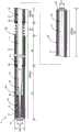
图1是示出了第一实施方式的导丝的整体结构的局部截面概要图。FIG. 1 is a partial cross-sectional schematic view showing the overall structure of the guide wire according to the first embodiment.
图2是例示旋转追随性试验中使用的样品1~5的结构的图。FIG. 2 is a diagram illustrating the structures of Samples 1 to 5 used in the rotation followability test.
图3是比较旋转追随性试验中使用的样品1~5的结构的说明图。FIG. 3 is an explanatory diagram for comparing the structures of Samples 1 to 5 used in the rotational followability test.
图4是用于说明旋转追随性试验的试验方法的图。FIG. 4 is a diagram for explaining a test method of a rotation followability test.
图5是用于说明旋转追随性试验的试验结果的图。FIG. 5 is a diagram for explaining the test results of the rotation followability test.
图6是示出了第二实施方式中导丝的整体结构的局部截面概要图。6 is a partial cross-sectional schematic view showing the overall structure of the guide wire in the second embodiment.
图7是示出了第三实施方式中导丝的整体结构的局部截面概要图。7 is a partial cross-sectional schematic view showing the overall structure of the guide wire in the third embodiment.
图8是示出了第四实施方式中导丝的整体结构的局部截面概要图。8 is a partial cross-sectional schematic view showing the overall structure of the guide wire in the fourth embodiment.
图9是示出了第五实施方式中导丝的整体结构的局部截面概要图。9 is a partial cross-sectional schematic view showing the overall structure of the guide wire in the fifth embodiment.
图10是示出了第六实施方式中导丝的整体结构的局部截面概要图。10 is a partial cross-sectional schematic view showing the overall structure of the guide wire in the sixth embodiment.
图11是示出了第七实施方式中导丝的整体结构的局部截面概要图。11 is a partial cross-sectional schematic view showing the overall structure of the guide wire in the seventh embodiment.
图12是示出了第八实施方式中导丝的整体结构的局部截面概要图。12 is a partial cross-sectional schematic view showing the overall structure of the guide wire in the eighth embodiment.
图13是示出了第九实施方式中导丝的整体结构的局部截面概要图。13 is a partial cross-sectional schematic view showing the overall structure of the guide wire in the ninth embodiment.
具体实施方式Detailed ways
(第一实施方式)(first embodiment)
图1是示出了第一实施方式的导丝1的整体结构的局部截面概要图。导丝1为在将导管插入血管或消化器官中时所使用的医疗器具,其具有芯轴10、线圈体20、内侧线圈体30、前端接合部51、基端接合部52、内侧接合部55、第一中间固定部61、第二中间固定部62、第一树脂皮膜71以及第二树脂皮膜72。以下,将图1的左侧称为导丝1和各组成构件的“前端侧”,并且将图1的右侧称为导丝1和各组成构件的“基端侧”。FIG. 1 is a partial cross-sectional schematic view showing the overall structure of the guide wire 1 according to the first embodiment. The guide wire 1 is a medical instrument used when a catheter is inserted into a blood vessel or a digestive organ, and includes a
芯轴10是基端侧为粗径、前端侧为细径的前端变细的细长形状构件。芯轴10,可由例如不锈钢合金(SUS302、SUS304、SUS316等)、Ni-Ti合金等超弹性合金、钢琴线、镍-铬系合金、钴合金以及钨等材料形成。芯轴10,也可以由除上述以外的公知材料形成。芯轴10的长度不受特别限定,例如可以是600mm~3000mm的范围。芯轴10从基端侧到前端侧依次具有粗径部11、锥形部12和细径部13。The
粗径部11是芯轴10中外径最大的最大外径部,并且从芯轴10的基端朝向前端侧外径恒定。在粗径部11的基端形成有基端接合部52。粗径部11的外径D1没有特别限定,例如可以是0.1mm~0.5mm的范围。粗径部11的长度也没有特别限定,例如可以是560mm~2960mm的范围。The
锥形部12形成在粗径部11与细径部13之间,并且从基端朝向前端外径变细。细径部13设置在芯轴10的前端,并且在细径部13的前端形成有前端接合部51。The tapered
线圈体20由一个线圈或连接多个线圈的构件构成,以覆盖芯轴10的几乎整个外周的方式卷绕在芯轴10上。线圈体20通过前端接合部51、基端接合部52、第一中间固定部61以及第二中间固定部62固定到芯轴10上。The
构成线圈体20的线圈可以是螺旋状地卷绕一根编丝而形成圆筒形的单线圈,也可以是将捻合多根编丝的绞线形成为圆筒形的中空绞线线圈。此外,线圈体20也可以通过组合单线圈和中空绞线线圈而构成。在此,对线圈体20的、比第二中间固定部62更靠近前端侧由单线圈构成、且比第二中间固定部62更靠近基端侧由中空绞线线圈构成的情况进行说明。The coil constituting the
线圈体20可以由,例如不锈钢合金(SUS302、SUS304、SUS316等)、Ni-Ti合金等超弹性合金,钢琴线、镍-铬系合金、钴合金,钨等放射线透过性合金,金、铂、钨或包括这些元素的合金(例如,铂-镍合金)等放射线不透性合金形成。线圈体20,也可以由除上述以外的公知材料形成。线圈体20的长度几乎与芯轴10的长度相等。线圈体20构造成外径D2恒定。外径D2没有特别限定,例如可以是0.3mm~1.5mm的范围。The
线圈体20的前端,通过前端接合部51与芯轴10的前端接合。前端接合部51由银焊料、金焊料、锌、Sn-Ag合金或Au-Sn合金等金属焊料形成,利用该金属焊料将线圈体20的前端与芯轴10的前端固定连接。另外,前端接合部51也可以由环氧系粘合剂等粘合剂来形成,利用粘合剂将线圈体20的前端与芯轴10的前端固定连接。线圈体20的基端,通过基端接合部52与芯轴10的基端接合。基端接合部52可以由与前端接合部51相同的材料形成,也可以由与前端接合部51不同的材料形成。The front end of the
线圈体20的中间部附近的一部分,通过第一中间固定部61固定到芯轴10的粗径部11上。并且,线圈体20的中间部附近的另一部分,通过第二中间固定部62固定到芯轴10的粗径部11上。第二中间固定部62位于比第一中间固定部61更靠近基端侧的位置,在这里,其是构成线圈体20的单线圈与中空绞线线圈的连接部(边界部)。第一中间固定部61和第二中间固定部62可以由,与前端接合部51和基端接合部52相同的材料形成,也可以由不同的材料形成。A part of the vicinity of the middle portion of the
线圈体20具有线圈节距不同的、疏卷部22和密卷部(第一密卷部23a、第二密卷部23b)。线圈体20从前端侧朝向基端侧依次形成有第一密卷部23a、疏卷部22以及第二密卷部23b,在这里,第一密卷部23a和疏卷部22形成为同一单线圈,第二密卷部23b形成为中空绞线线圈。The
疏卷部22是线圈体20中线圈节距相对稀疏的部分。具体地,疏卷部22与密卷部23(第一密卷部23a、第二密卷部23b)相比线圈节距稀疏,在这里,线圈节距为第一密卷部23a的0.80倍~0.99倍左右。这里所说的疏卷部22的线圈节距,是指疏卷部22的线圈节距的平均值,是用疏卷部22的轴向长度、除以疏卷部22的线圈匝数而得出的值。第一密卷部23a的线圈节距,是指第一密卷部23a的线圈节距的平均值,是用第一密卷部23a的轴向长度、除以第一密卷部23a的线圈匝数而得出的值。疏卷部22的基端,设置在与第二中间固定部62相邻的位置。The sparse winding
密卷部23(第一密卷部23a、第二密卷部23b)是线圈体20中线圈节距相对密集的部分。第一密卷部23a与第二密卷部23b的线圈节距可以相等,也可以不同。第一密卷部23a的前端固定在前端接合部51上,基端与疏卷部22的前端接触。第二密卷部23b的前端与疏卷部22的基端、以及第二中间固定部62接触,第二密卷绕部23b的基端固定在基端接合部52上。The densely wound portion 23 (the first densely wound
这样,线圈体20在比疏卷部22的前端更靠近前端侧、以及比疏卷部22的基端更靠近基端侧的两者处,配置有密卷部(第一密卷部23a、第二密卷部23b)。此外,疏卷部22设置在线圈体20中、覆盖粗径部11的位置处。另外,疏卷部22设置在线圈体20中、覆盖芯轴10中未卷绕内侧线圈体30的部分的位置处。关于它们所带来的效果的一个示例将在后面进行描述。In this way, the
内侧线圈体30,由单线圈或中空绞线线圈构成,并以覆盖芯轴10的前端侧的外周的方式卷绕在芯轴10上。其中,内侧线圈体30卷绕在芯轴10的细径部13和锥形部12的一部分上。内侧线圈体30比芯轴10和线圈体20的长度短,并且通过前端接合部51和内侧接合部55固定在芯轴10上。The
内侧线圈体30的长度不受特别限定,例如可以是10mm~100mm。内侧线圈体30构造成外径D3恒定。外径D3没有特别限定,例如可以是0.1mm~0.5mm的范围。内侧线圈体30的前端,通过前端接合部51与芯轴10的前端接合。内侧线圈体30的基端,通过内侧接合部55与芯轴10的锥形部12接合。内侧接合部55可以由与前端接合部51相同的材料形成,也可以由不同的材料形成。The length of the
内侧线圈体30的卷绕方向,可以与线圈体20的卷绕方向相同,也可以不同。此外,内侧线圈体30的线圈节距,可以与线圈体20的线圈节距相同,也可以不同。另外,通过使内侧线圈体30的线圈节距与线圈体20的线圈节距不同,从而能够在导丝1的前端部弯曲变形时,抑制这些编丝之间的咬合现象。The winding direction of the
在本实施方式的导丝1中,将从导丝1的前端到第一中间固定部61的部分称为“第一区间部P1”,将从第一中间固定部61到疏卷部22的前端的部分称为“第二区间部P2”,将从疏卷部22的前端到基端的部分称为“第三区间部P3”,将从疏卷部22的基端到导丝1的基端的部分称为“第四区间部P4”。第一区间部P1的长度,例如可以是40mm~400mm的范围。第二区间部P2的长度,例如可以是250mm~1000mm的范围。第三区间部P3的长度,例如可以是10mm~100mm的范围。第四区间部P4的长度,例如可以是300mm~1500mm的范围。In the guide wire 1 of the present embodiment, the portion from the distal end of the guide wire 1 to the first intermediate fixing
此时,线圈体20在第一区间P1和第二区间P2形成有第一密卷部23a,在第三区间P3形成有疏卷部22,在第四区间P4形成有第二密卷部23b。线圈体20中,位于第一区域部P1和第四区域部P4的部分的外表面被第一树脂皮膜71覆盖,位于第二区域部P2的部分的外表面被第二树脂皮膜72覆盖。而位于线圈体20的第三区间部P3的部分的外表面,未形成树脂皮膜而是露出的。At this time, the
即,导丝1除疏卷部22以外的部分被树脂皮膜(第一树脂皮膜71或第二树脂皮膜72)覆盖,而疏卷部22没有被树脂皮膜覆盖。换言之,线圈体20在第一密卷部23a和第二密卷部23b的外表面形成有树脂皮膜,在疏卷部22上树脂皮膜断开。由此产生的效果的一个示例将在后面进行描述。That is, the guide wire 1 is covered with the resin film (the
第一树脂皮膜71由比线圈体20的表面更难以与外部产生摩擦的疏水性树脂构成,在此,使用硅树脂等。另外,作为疏水性树脂除了硅树脂以外,还可以使用聚氨酯、聚乙烯、聚氯乙烯、聚酯、聚丙烯、聚酰胺或聚苯乙烯等。The
第二树脂皮膜72由具有亲水基的树脂制构成,例如可由羧甲基淀粉等淀粉系,羧甲基纤维素等纤维素系,藻酸、肝素、甲壳质、壳聚糖、透明质酸等多糖类,明胶等天然水溶性高分子物质,以及聚乙烯醇、聚环氧乙烷、聚乙二醇、聚丙二醇、聚丙烯酸盐、甲基乙烯基醚马来酸酐共聚物、甲基乙烯基醚马来酸酐酸盐、甲基乙烯基醚马来酸酐铵盐、马来酸酐乙酯共聚物、聚邻苯二甲酸羟乙基酯共聚物、聚二羟甲基丙酸酯、聚丙烯酰胺、聚丙烯酰胺季铵化物、聚乙烯吡咯烷酮、聚乙烯亚胺、聚乙烯磺酸盐、水溶性尼龙等合成水溶性高分子物质构成。第二树脂皮膜72在含水时呈膨润状态,并且与第一树脂皮膜71相比,滑动性和血栓附着预防性进一步提高。The
第二树脂皮膜72与比第一树脂皮膜71相比更具有润滑性,能够进一步减小体内的摩擦阻力。另一方面,若用第二树脂皮膜72覆盖从前端到基端的导丝的整个外表面,则导丝在体内过度滑动,会造成在体内的分支等中的操作性降低。如本实施方式所示,通过在导丝的前端侧和基端侧设置第一树脂皮膜71,在中间部的一部分上设置第二树脂皮膜72,可以提高操作性。The
(本实施方式的效果例)(Example of effects of this embodiment)
根据以上描述的本实施方式的导丝1,线圈体20在前端接合部51与基端接合部52之间具有疏卷部22,因此可以抑制弯曲时的、导丝的旋转追随性能的降低。旋转追随性能是指,当旋转导丝的基端时、前端追随基端的旋转而旋转的性能。换言之,旋转追随性能是指经由芯轴和线圈体的旋转的传递性能。According to the guide wire 1 of the present embodiment described above, since the
本实施方式的导丝1,即使在弯曲时线圈体20中位于弯曲内侧的部分在导丝1的轴向上被压缩,也可以通过疏卷部22的线圈间的间隙来缓解线圈的卡塞。因此,可以抑制导丝1弯曲时、因线圈卡塞而导致的旋转追随性能的降低。另外,由于导丝1弯曲时,通过疏卷部22线圈的卡塞得到缓解,因此线圈体20与芯轴10接触,从而可以缓解芯轴10在轴向上被拉伸的状态。因此,在导丝1弯曲时,线圈体20的内周与芯轴10的外周接触,从而可以抑制由于芯轴10在轴向上被拉伸而导致的旋转追随性能的降低。关于通过本实施方式的导丝1来抑制弯曲时的旋转追随性能降低这一点,将使用图2~图5在后面进行说明。In the guide wire 1 of the present embodiment, even if the portion of the
此外,根据本实施方式的导丝1,由于线圈体20在比疏卷部22的前端更靠近前端侧、以及比疏卷部22的基端更靠近基端侧的两者处具有密卷部23,因此可以通过两侧的密卷部23抑制导丝1的滑动性能的降低,并且可以通过疏卷部22抑制弯曲时导丝1的旋转追随性能的降低。通常,在线圈体中,与疏卷部相比,密卷部在外内的滑动性能更高。根据本实施方式的导丝1,可以通过疏卷部22两侧的密卷部23确保滑动性能,并且可以通过疏卷部22、抑制弯曲时导丝1的旋转追随性能的降低。Further, according to the guide wire 1 of the present embodiment, the
此外,根据本实施方式的导丝1,由于线圈体20在比疏卷部22的前端更靠近前端侧的第一密卷部23a、以及比疏卷部22的基端更靠近基端侧的第二密卷部23b的各自外表面上形成有树脂皮膜71、72,且树脂皮膜71、72在疏卷部22上是断开的,因此可以进一步抑制导丝1弯曲时的旋转追随性能的降低。通常,具体地,在线圈体的外表面上形成树脂皮膜时,线圈之间的相对运动(线圈体受到束缚)会受到树脂皮膜的限制。当线圈体受到树脂皮膜束缚时,弯曲时的导丝的旋转追随性能进一步降低。根据本实施方式的导丝1,由于在疏卷部22上未形成树脂皮膜,因此在疏卷部22处,树脂皮膜对线圈体20的束缚得到缓解。由此,可以进一步抑制使导丝1弯曲时的旋转追随性能的降低。并且,当试图在疏卷部22的外表面上形成树脂皮膜时,用于形成树脂皮膜的薄膜形成液从疏卷部22的外表面进入芯轴10,从而有可能使线圈件20与芯轴10接合而降低旋转追随性能。由于在疏卷部22上不形成树脂皮膜,可以抑制线圈体20与芯轴10之间产生粘接。In addition, according to the guide wire 1 of the present embodiment, since the
此外,根据本实施方式的导丝1,由于疏卷部22设置在线圈体20中、覆盖最大外经部即粗径部11的位置处,因此在使导丝弯曲时,通过最大外径部与线圈体20的接触,可以缓和芯轴10在轴向上被拉伸的状态。由此,可以抑制使导丝弯曲时的旋转追随性能的降低。In addition, according to the guide wire 1 of the present embodiment, since the sparse winding
另外,根据本实施方式的导丝1,由于疏卷部22设置在线圈体20上、覆盖芯轴10中未卷绕内侧线圈体30的部分的位置处,因此在使导丝1弯曲时,可以抑制内侧线圈体30与线圈体20的编丝之间发生啮合,并且可以抑制导丝1的旋转追随性能的降低。In addition, according to the guide wire 1 of the present embodiment, since the loose winding
(旋转追随性试验)(rotation followability test)
使用图2~图5,对通过本实施方式的导丝来抑制弯曲时的旋转追随性能的降低进行说明。这里,为了证明本实施方式的导丝的效果,对包含具有本实施方式的结构的导丝的五个样品进行了旋转追随性试验。旋转追随性试验是指,对导丝的旋转追随性能进行定量性测量的试验。With reference to FIGS. 2 to 5 , the guide wire according to the present embodiment will describe the suppression of the decrease in the rotational follow-up performance at the time of bending. Here, in order to prove the effect of the guide wire of the present embodiment, a rotation followability test was performed on five samples including the guide wire having the structure of the present embodiment. The rotational followability test is a test for quantitatively measuring the rotational followability of the guide wire.
图2是例示出旋转追随性试验中所使用的导丝样品1~5的结构的图。在图2中,仅示出各样品的第一中间固定部61与第二中间固定部62之间的部分。图3是对样品1~5的结构进行比较的说明图。样品1~5与上述本实施方式的导丝1(图1)相同,具有芯轴10、线圈体20(20a~20e)、第一中间固定部61、第二中间固定部62、以及第一树脂皮膜71。样品1~5在图2所示的第一中间固定部61与第二中间固定部62之间的部分的结构彼此不同。除此以外的部分具有与本实施方式相同的结构(图1)。样品1~5在第一中间固定部61附近、以及第二中间固定部62附近,其第一树脂皮膜71的有无、疏卷部22的有无的组合各不相同。FIG. 2 is a diagram illustrating the structure of guide wire samples 1 to 5 used in the rotational followability test. In FIG. 2, only the part between the 1st intermediate|middle fixing|fixed
如图2所示,样品1的线圈体20a在第一中间固定部61与第二中间固定部62之间,整体形成为密卷部23。并且,线圈体20a在第二中间固定部62附近未形成第一树脂皮膜71而是露出的,在除此以外的部分则形成有第一树脂皮膜71。因此,如图3所示,样品1在第一中间固定部61附近处,第一树脂皮膜71为“有”,疏卷部22为“无”。同时,在第二中间固定部62附近处,第一树脂皮膜71为“无”,疏卷部22为“无”。As shown in FIG. 2 , the
如图2所示,样品2的线圈体20b,在第二中间固定部62附近处形成有疏卷部22,除此以外的部分形成为密卷部23。并且,与样品1相同,线圈体20b在第二中间固定部62附近未形成第一树脂皮膜71而是露出的,在除此以外的部分形成有第一树脂皮膜71。因此,如图3所示,样品2在第一中间固定部61附近处,第一树脂皮膜71为“有”,疏卷部22为“无”。并且在第二中间固定部62附近处,第一树脂皮膜71为“无”,疏卷部22为“有”。除了第一中间固定部61与第二中间固定部62之间的树脂皮膜的种类为第一树脂皮膜71这一点外,样品2形成为与第一实施方式的导丝1相同的结构。As shown in FIG. 2 , in the
如图2所示,样品3的线圈体20c与样品1的线圈体20a相同,在第一中间固定部61与第二中间固定部62之间,整体形成为密卷部23。另一方面,线圈体20c在第一中间固定部61附近和第二中间固定部62附近的两者处,未形成第一树脂皮膜71而是露出的,在除此以外的部分形成有第一树脂皮膜71。因此,如图3所示,样品3在第一中间固定部61附近处,第一树脂皮膜71为“无”、疏卷部22为“无”。并且在第二中间固定部62附近处,第一树脂皮膜71为“无”、疏卷部22为“无”。As shown in FIG. 2 , the
如图2所示,样品4的线圈体20d在第一中间固定部61附近与第二中间固定部62附近的两者处,分别形成有疏卷部22(第一疏卷部22a、第二疏卷部22b)。并且,线圈体20d在第一中间固定部61附近和第二中间固定部62附近的两者处,未形成第一树脂皮膜71而是露出的,在除此以外的部分形成有第一树脂皮膜71。因此,如图3所示,样品4在第一中间固定部61附近处,第一树脂皮膜71为“无”、疏卷部22为“有”。此外,在第二中间固定部62附近处,第一树脂皮膜71为“无”、疏卷部22为“有”。As shown in FIG. 2 , in the
如图2所示,样品5的线圈体20e与样品1的线圈体20a相同,在第一中间固定部61与第二中间固定部62之间,整体形成为密卷部23。另一方面,线圈体20e在第一中间固定部61与第二中间固定部62之间,整体上形成有第一树脂皮膜71。因此,如图3所示,样品5在第一中间固定部61附近处,第一树脂皮膜71为“有”、疏卷部22为“无”。并且在第二中间固定部62附近处,第一树脂皮膜71为“有”、疏卷部22为“无”。As shown in FIG. 2 , the
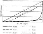
图4是用于说明旋转追随性试验的试验方法的图。使用管81,制作半径为50mm的圆形的圈,制成在圈的前后形成直线部分的试验路径。从该试验路径的一个开口部(图4右侧的开口部)插入样品导丝84。将样本导丝84向内推进,直至其前端从管81的另一个开口部突出。在该状态下,使导丝84的基端侧旋转。对于各样品1~5,测量在使基端侧旋转时、前端侧旋转了几度。FIG. 4 is a diagram for explaining a test method of a rotation followability test. Using the
图5是用于说明旋转追随性试验的试验结果的图。在图5的表中,横轴示出样品基端侧的旋转角度(输入角度),纵轴示出样品前端侧的旋转角度(输出角度)。图5的理想值是指,示出了前端部完全跟随基端部的旋转的状态。在线圈体20中未形成疏卷部22的样品1、3和5中,旋转追随性能相对较低,在线圈体20中形成有疏卷部22的样品2、4中,旋转追随性能相对较高。由此可知,通过在线圈体20上设置疏卷部22、可以抑制导丝在弯曲时的旋转追随性能的下降。FIG. 5 is a diagram for explaining the test results of the rotation followability test. In the table of FIG. 5 , the horizontal axis represents the rotation angle (input angle) on the side of the sample proximal end, and the vertical axis represents the rotation angle (output angle) on the sample front end side. The ideal value in FIG. 5 shows a state in which the distal end portion completely follows the rotation of the proximal end portion. In the samples 1, 3 and 5 in which the
(第二实施方式)(Second Embodiment)
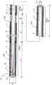
图6是示出了第二实施方式的导丝1A的整体结构的局部截面概要图。在第一实施方式的导丝1中,疏卷部22仅形成在与第二中间固定部62相邻的一处位置(图1)。但是,疏卷部22也可以形成在与第二中间固定部62相邻的位置以外的部分,还可以形成为多个。例如,在图6所示的第二实施方式的导丝1A中,线圈体20A在第一中间固定部61附近与第二中间固定部62附近的两者处,分别形成有疏卷部22(第一疏卷部22a、第二疏卷部22b)。第一疏卷部22a的前端设置在与第一中间固定部61相邻的位置处。第二疏卷部22b的基端设置在与第二中间固定部62相邻的位置处。在线圈体20A中,从前端侧向基端侧依次形成有第一密卷部23c、第一疏卷部22a、第二密卷部23d、第二疏卷部22b以及第三密卷部23e。FIG. 6 is a partial cross-sectional schematic view showing the overall structure of the
这里,将从导丝1A的前端到第一中间固定部61的部分称为“第一区间部P11”,将从第一中间固定部61到第一疏卷部22a的基端的部分称为“第二区间部P12”,将从第一疏卷部22a的基端到第二疏卷部22b的前端的部分称为“第三区间部P13”,将从第二疏卷部22b的前端到第二中间固定部62的部分称为“第四区间部P14”,将从第二中间固定部62到导丝1A的基端的部分称为“第五区间部P15”。Here, the portion from the distal end of the
此时,线圈体20A在第一区间部P11形成有第一密卷部23c,在第二区间部P12形成有第一疏卷部22a,在第三区间部P13形成有第二密卷部23d,在第四区间部P14形成有第二疏卷部22b,在第五区间部P15形成有第三密卷部23e。线圈体20A中,位于第一区间部P11和第五区间部P15的部分的外表面被第一树脂皮膜71覆盖,位于第三区间部P13的部分的外表面被第二树脂皮膜72覆盖。位于线圈体20A的第二区间部P12以及第四区间部P14的部分的外表面,未形成树脂皮膜而是露出的。At this time, in the
根据第二实施方式的导丝1A,也可以抑制使导丝弯曲时的旋转追随性能的降低。具体地,第二实施方式的导丝1A除树脂皮膜的结构以外,与上述旋转追随性试验中使用的样品4相同。由于在旋转追随性试验中使用的样品4,其旋转追随性较高,因此可知即使在第二实施方式的导丝1A中,也可以抑制弯曲时导丝的旋转追随性能的降低。另外,疏卷部22可以设置在任意位置,而与中间固定部(第一中间固定部61和第二中间固定部62)的位置无关。此外,疏卷部22还可以设置在导丝的前端处。但是,疏卷部22优选设置在导丝的中间部附近。According to the
(第三实施方式)(third embodiment)
图7是示出了第三实施方式的导丝1B的整体结构的局部截面概要图。在第一实施方式的导丝1中,在密卷部23(第一密卷部23a、第二密卷部23b)的整个外表面上形成有树脂皮膜。但是,也可以不在密卷部23的外表面的一部分上形成树脂皮膜。例如,在图7所示的第三实施方式的导丝1B中,线圈体20B在从第一密卷部23a的前端向基端的预定范围的外表面上形成有树脂皮膜(第一树脂皮膜71或第二树脂皮膜72),但第一密卷部23a的后端侧的外表面的一部分处,未形成树脂皮膜而是露出的。除此以外的结构与第一实施方式的导丝1相同。换言之,线圈体20B在自第一密卷部23a的前端起预定范围的外表面、以及第二密卷部23b的外表面上形成有树脂皮膜,而在疏卷部22和第一密卷部23a的后端侧的一部分上,树脂皮膜是断开的。FIG. 7 is a partial cross-sectional schematic view showing the overall structure of the
这里,将从导丝1B的前端到第一中间固定部61的部分称为“第一区间部P21”,将从第一中间固定部61到第一密卷部23a的后端侧的中途地点的部分称为“第二区间部P22”,将从第一密卷部23a的后端侧的中途地点到疏卷部22的前端的部分称为“第三区间部P23”,将从疏卷部22的前端到基端的部分称为“第四区间部P24”,将从疏卷部22的基端到导丝1B的基端的部分称为“第五区间部P25”。Here, the portion from the front end of the
此时,线圈体20B在第一区间部P21、第二区间部P22以及第三区间部P23形成第一密卷部23a,在第四区间部P24形成疏卷部22,在第五区间部P25形成第二密卷部23b。在线圈体20B中,位于第一区间部P21和第五区间部P25的部分的外表面被第一树脂皮膜71覆盖,位于第二区间部P22的部分的外表面被第二树脂皮膜72覆盖。位于线圈体20B的第三区间部P23以及第四区间部P24的部分的外表面,未形成树脂皮膜而是露出的。At this time, the
根据第三实施方式的导丝1B,也可以抑制使导丝弯曲时的旋转追随性能的降低。并且,根据第三实施方式的结构,在线圈体20的外表面上形成树脂皮膜时,用于形成树脂皮膜的皮膜形成液从线圈体20的外表面进入芯轴10,从而可以减少由于线圈件20与芯轴10粘粘接而导致的旋转追随性能降低状态的发生。具体地,为了在整个密卷部23a上形成树脂皮膜,而在第一密卷部23a与疏卷部22的边界位置涂覆皮膜形成液时,由于毛细现象等原因,皮膜形成液会意外地从疏卷部22的外表面进入芯轴10,从而有时会导致线圈件20与芯轴10粘接而使旋转追随性能降低。如第三实施方式的导丝1B那样,第一密卷部23a中,仅在自前端起的预定范围内(第二区间部P22)形成树脂皮膜,而在后端侧的一部分(第三区间部P23)处不形成树脂皮膜,通过采用这种结构,能够抑制在制造中皮膜形成液意外地从疏卷部22的外表面进入芯轴10。另外,第一密卷部23a中,在上述位置以外的位置处也可以具有未形成树脂皮膜的部分。此外,从第二密卷部23b的前端起的规定范围也可以不形成树脂皮膜。According to the
(第四实施方式)(Fourth Embodiment)
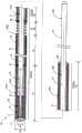
图8是示出了第四实施方式的导丝1C的整体结构的局部截面概要图。第一实施方式的导丝1设有一个疏卷部22(图1),第二实施方式的导丝1A设有两个疏卷部22(图6)。但是,疏卷部22的数量不限于上述个数。例如,在图8所示的第四实施方式的导丝1C中,线圈体20C在第一中间固定部61附近和第二中间固定部62附近之外,在导丝1C的前端与第一中间固定部61之间也形成有疏卷部22。即,第四实施方式的线圈体20C具有三个疏卷部22(第一疏卷部22c、第二疏卷部22d、第三疏卷部22e),并从前端侧向基端侧依次形成有第一密卷部23f、第一疏卷部22c、第二密卷部23g、第二疏卷部22d、第三密卷部23h、第三疏卷部22e以及第四密卷部23i。FIG. 8 is a partial cross-sectional schematic view showing the overall structure of the guide wire 1C according to the fourth embodiment. The guide wire 1 of the first embodiment is provided with one sparse coil portion 22 ( FIG. 1 ), and the
这里,将从导丝1C的前端到第一疏卷部22c的前端的部分称为“第一区间部P31”,将从第一疏卷部22c的前端到后端的部分称为“第二区间部P32”,将从第一疏卷部22c的后端到第一中间固定部61的部分称为“第三区间部P33”,将从第一中间固定部61到第二疏卷部22d的基端的部分称为“第四区间部P34”,将从第二疏卷部22d的基端到第三疏卷部22e的前端的部分称为“第五区间部P35”,将从第三疏卷部22e的前端到第二中间固定部62的部分称为“第六区间部P36”,将从第二中间固定部62到导丝1C的基端的部分称为“第七区间部P37”。Here, the part from the front end of the guide wire 1C to the front end of the first sparsely coiled
此时,线圈体20C在第一区间部P31形成有第一密卷部23f,在第二区间部P32形成有第一疏卷部22c,在第三区间部P33形成有第二密卷部23g,在第四区间部P34形成有第二疏卷部22d,在第五区间部P35形成有第三密卷部23h,在第六区间部P36形成有第三疏卷部22e,在第七区间部P37形成有第四密卷部23i。线圈体20C中,位于第一区间部P31、第三区间部P33以及第七区间部P37的部分的外表面被第一树脂皮膜71覆盖,位于第五区间部P35的部分的外表面被第二树脂皮膜72覆盖。位于线圈体20C的第二区间部P32、第四区间部P34以及第六区间部P36的部分的外表面,未形成树脂皮膜而是露出的。At this time, in the
根据第四实施方式的导丝1C,通过三个疏卷部22(第一疏卷部22c、第二疏卷部22d、第三疏卷部22e)的线圈间的间隙,也可以缓解弯曲时的线圈的卡塞。并且,通过缓和线圈的卡塞,可以缓和弯曲时线圈体20C与芯轴10接触而使芯轴10在轴向上被拉伸的状态。因此,根据第四实施方式的导丝1C,也可以抑制使导丝弯曲时的旋转追随性能的降低。另外,导丝还可以设置四个以上的疏卷部22。According to the guide wire 1C of the fourth embodiment, the gap between the coils of the three sparse winding portions 22 (the first sparse winding
(第五实施方式)(Fifth Embodiment)
图9是示出了第五实施方式的导丝1D的整体结构的局部截面概要图。第一实施方式的导丝1包括内侧线圈体30(图1)。但是,也可以如图9所示的第五实施方式的导丝1D那样,不设置内侧线圈体。即使是此结构,也可以通过疏卷部22缓和弯曲时的线圈的卡塞。并且,在弯曲时,线圈体20D与芯轴10接触,从而可以缓和芯轴10在轴向上被拉伸的状态。因此,根据第五实施方式的导丝1D,也可以抑制使导丝弯曲时的旋转追随性能的降低。FIG. 9 is a partial cross-sectional schematic view showing the overall structure of the
(第六实施方式)(Sixth Embodiment)
图10是示出第六实施方式的导丝1E的整体结构的局部截面概要图。第一实施方式的导丝1,在线圈体20的外表面上形成有两种树脂皮膜(第一树脂皮膜71和第二树脂皮膜72)(图1)。但是,形成在线圈体20的外表面上的皮膜的结构不限于上述结构。例如,如图10所示第六实施方式的导丝1E那样,线圈体20E的疏卷部22以外的整体也可以被单一种类的树脂皮膜(在此为第二树脂皮膜72)覆盖。另外,导丝1还可以被三种以上的树脂皮膜覆盖。即使是这些结构,通过疏卷部22,也可以抑制使导丝弯曲时的旋转追随性能的降低。FIG. 10 is a partial cross-sectional schematic view showing the overall structure of the
(第七实施方式)(Seventh Embodiment)
图11是示出第七实施方式的导丝1F的整体结构的局部截面概要图。第一实施方式的导丝1中,线圈体20的疏卷部22设置在,覆盖芯轴10的最大外径部即粗径部11的位置处(图1)。但是,线圈体20的疏卷部22,还可以不设置在芯轴10的最大外径部的位置处。例如,在图11所示的第七实施方式的导丝1F中,芯轴10F从基端侧到前端侧依次具有第一粗径部15、第二粗径部16、锥形部17以及细径部18。第一粗径部15是芯轴10F中外径最大的最大外径部、且外径恒定。第二粗径部16,其外径小于第一粗径部15,且外径恒定。锥形部17和细径部18与第一实施方式的锥形部12和细径部13相同。并且,线圈体20F的疏卷部22,不设置在覆盖作为最大外径部的第一粗径部15的位置处,而设置在覆盖第二粗径部16的位置处。11 is a partial cross-sectional schematic view showing the overall structure of a guide wire 1F according to a seventh embodiment. In the guide wire 1 of the first embodiment, the sparse winding
即使是此结构,通过疏卷部22,也可以缓和弯曲时的线圈的卡塞。并且,在弯曲时,线圈体20F与芯轴10F的第二粗径部16接触,从而可以缓和芯轴10F在轴向上被拉伸的状态。因此,根据第七实施方式的导丝1F,也可以抑制使导丝弯曲时的旋转追随性能的降低。Even in this configuration, the
(第八实施方式)(Eighth Embodiment)
图12是示出第八实施方式的导丝1G的整体结构的局部截面概要图。第一实施方式的导丝1在基端接合部52处,线圈体20的基端连接到芯轴10的基端(图1)。但是,线圈体20的基端,也可以固定到芯轴10的基端以外的部位。例如,如图12所示第八实施方式的导丝1G那样,线圈件20G的基端也可以固定到芯轴10G的中间部附近。这里,线圈体20G的基端通过中间接合部56与芯轴10G的粗径部19接合。中间接合部56可以由与前端接合部51相同的材料形成。FIG. 12 is a partial cross-sectional schematic view showing the overall structure of the
即使是此结构,也可以通过疏卷部22缓和弯曲时的线圈的卡塞。并且,在弯曲时,线圈体20G与芯轴10G的粗径部19接触,从而可以缓和芯轴10G在轴向上被拉伸的状态。因此,根据第八实施方式的导丝1G,也可以抑制使导丝弯曲时的旋转追随性能的降低。Even with this structure, the
(第九实施方式)(Ninth Embodiment)
图13是示出了第九实施方式的导丝1H的整体结构的局部截面概要图。第一实施方式的导丝1,设有两个中间固定部(第一中间固定部61、第二中间固定部62)(图1)。但是,中间固定部的数量可以是上述以外的结构。例如,如图13所示第九实施方式的导丝1H那样,可以不设置中间固定部。即使是此结构,通过疏卷部22(第一疏卷部22a、第二疏卷部22b),也可以缓和弯曲时的线圈的卡塞。并且,通过两个疏卷部22,在弯曲时线圈体20H与芯轴10接触,从而可以缓和芯轴10在轴向上被拉伸的状态。因此,根据第九实施方式的导丝1H,也可以抑制使导丝弯曲时的旋转追随性能的降低。另外,中间固定部可以形成为三个以上,也可以形成为一个。此外,宽度和大小、以及固定方法也可以是上述以外的结构。FIG. 13 is a partial cross-sectional schematic view showing the overall structure of a
(本实施方式的变形例)(Variation of this embodiment)
本发明不限于上述实施方式,可在不脱离其主旨的范围内以各种方式实施,例如也可以是如下所述的变形。The present invention is not limited to the above-described embodiments, and can be implemented in various forms without departing from the gist thereof, and for example, modifications as described below are also possible.
(变形例1)(Variation 1)
在第一至第九实施方式的导丝1、1A~1H中,线圈体20、20A~20H的外表面的至少一部分上,形成有树脂皮膜(第一树脂皮膜71或第二树脂皮膜72)。但是,导丝还可以是在线圈体的外表面上完全不形成树脂皮膜、而整体露出的。此外,还可以是导丝的线圈体20的外表面的至少一部分被金属等树脂以外的膜覆盖。第一至第九实施方式的导丝中,在疏卷部22上不形成树脂皮膜。但是,也可以在疏卷部22的至少一部分上形成树脂皮膜。此外,在线圈体的外表面上形成的树脂皮膜,在疏卷部22上也可以不断开,而是通过疏卷部22将形成在两侧的密卷部23上的树脂皮膜连接起来。另外,优选在疏卷部22上不形成树脂皮膜。In the
(变形例2)(Variation 2)
第一实施方式的导丝1中,还可以在线圈体20和内侧线圈体30这两者的同一位置处设置疏卷部22。在这种情况下,在使导丝1的前端弯曲变形时,可以使弯曲变得容易,并提高塑性变形性能。In the guide wire 1 of the first embodiment, the sparse winding
(变形例3)(Variation 3)
第一实施方式的导丝1,其线圈体20的外径D2可以不是恒定的。并且,导丝1的内侧线圈体30的外径D3也可以不是恒定的。此外,芯轴10的粗径部11的外径D1也可以不是恒定的。In the guide wire 1 of the first embodiment, the outer diameter D2 of the
(变形例4)(Variation 4)
第一实施方式的导丝1中,密卷部23可以不形成在疏卷部22的两侧,而是仅形成在单侧。即,疏卷部22也可以形成在线圈体20的前端或基端。另外,优选疏卷部22设置在线圈体20的中间附近处、且在两侧形成密卷部23。In the guide wire 1 of the first embodiment, the densely wound
(变形例5)(Variation 5)
第一实施方式的导丝1中,疏卷部22还可以设置在线圈体20上、覆盖芯轴10的卷绕有内侧线圈体30的部分的位置处。即使在此情况下,也可以抑制弯曲时的、导丝的旋转追随性能的降低。In the guide wire 1 of the first embodiment, the sparse winding
(变形例6)(Variation 6)
第一至第九实施方式的导丝的结构,还可以适当组合。例如,第二实施方式的导丝1A(图6)还可以如第三实施方式的密卷部23(图7)那样,不在外表面的一部分上形成树脂皮膜。此外,例如,可以如第五实施方式(图9)那样,不设置内侧线圈体30。另外,例如,第四实施方式的导丝1C(图8),还可以如第六实施方式的线圈体20E(图10)那样,疏卷部22以外的整体被单一种类的树脂皮膜覆盖。The structures of the guide wires of the first to ninth embodiments can also be appropriately combined. For example, in the
以上基于实施方式、变形例对本发明进行了说明,但上述形态的实施方式是为了便于理解本发明的示例,并不用以限制本发明。凡在本发明的精神以及权利要求请求范围之内所作的变形、改进以及等同替换等,均应包含在本发明的保护范围之内。另外,其技术特征如果在本说明书中没有被描述为必要的,则可以进行适当删减。As mentioned above, although this invention was demonstrated based on embodiment and a modification, the embodiment of the above-mentioned form is an example for easy understanding of this invention, and is not intended to limit this invention. All modifications, improvements and equivalent replacements made within the spirit of the present invention and the scope of the claims should be included within the protection scope of the present invention. In addition, if its technical features are not described as essential in this specification, appropriate deletions may be made.
附图标记说明Description of reference numerals
1、1A~1H…导丝1. 1A~1H…guide wire
10、10F、10G…芯轴10, 10F, 10G... Mandrels
11…粗径部11...Large diameter part
12…锥形部12…Tapered part
13…细径部13...Small diameter part
15…第一粗径部15...The first large diameter part
16…第二粗径部16...Second large diameter part
17…锥形部17…Tapered part
18…细径部18...Small diameter part
19…粗径部19...Large diameter part
20、20A~20H…线圈体20, 20A~20H...coil body
22…疏卷部22...Sparse Volume Department
23…密卷部23…Condensed Volume
30…内侧线圈体30…Inner coil body
51…前端接合部51…Front end joint
52…基端接合部52...Base end joint
55…内侧接合部55…Inside joint
56…中间接合部56…Intermediate joint
61…第一中间固定部61...First intermediate fixing part
62…第二中间固定部62...Second intermediate fixing part
71…第一树脂皮膜71...First resin film
72…第二树脂皮膜72...Second resin film
81…聚乙烯管81…Polyethylene pipe
84…导丝84…Guide wire
Claims (6)
Translated fromChinesePriority Applications (1)
| Application Number | Priority Date | Filing Date | Title |
|---|---|---|---|
| CN202210431928.XACN114796808A (en) | 2017-09-30 | 2017-09-30 | Guide wire |
Applications Claiming Priority (1)
| Application Number | Priority Date | Filing Date | Title |
|---|---|---|---|
| PCT/JP2017/035759WO2019064607A1 (en) | 2017-09-30 | 2017-09-30 | Guide wire |
Related Child Applications (1)
| Application Number | Title | Priority Date | Filing Date |
|---|---|---|---|
| CN202210431928.XADivisionCN114796808A (en) | 2017-09-30 | 2017-09-30 | Guide wire |
Publications (1)
| Publication Number | Publication Date |
|---|---|
| CN111372641Atrue CN111372641A (en) | 2020-07-03 |
Family
ID=65901375
Family Applications (2)
| Application Number | Title | Priority Date | Filing Date |
|---|---|---|---|
| CN201780094314.4APendingCN111372641A (en) | 2017-09-30 | 2017-09-30 | guide wire |
| CN202210431928.XAPendingCN114796808A (en) | 2017-09-30 | 2017-09-30 | Guide wire |
Family Applications After (1)
| Application Number | Title | Priority Date | Filing Date |
|---|---|---|---|
| CN202210431928.XAPendingCN114796808A (en) | 2017-09-30 | 2017-09-30 | Guide wire |
Country Status (6)
| Country | Link |
|---|---|
| US (1) | US11400262B2 (en) |
| EP (2) | EP4059557A3 (en) |
| JP (1) | JP6866493B2 (en) |
| KR (1) | KR20200028450A (en) |
| CN (2) | CN111372641A (en) |
| WO (1) | WO2019064607A1 (en) |
Cited By (1)
| Publication number | Priority date | Publication date | Assignee | Title |
|---|---|---|---|---|
| CN116472083A (en)* | 2020-11-26 | 2023-07-21 | 朝日英达科株式会社 | guide wire |
Families Citing this family (3)
| Publication number | Priority date | Publication date | Assignee | Title |
|---|---|---|---|---|
| JP7551285B2 (en)* | 2019-10-02 | 2024-09-17 | 朝日インテック株式会社 | Guidewires |
| US20210393924A1 (en)* | 2020-06-19 | 2021-12-23 | Becton, Dickinson And Company | Vascular access instrument and related devices and methods |
| US20230135237A1 (en)* | 2021-04-16 | 2023-05-04 | Bard Peripheral Vascular, Inc. | Strength-adjustable guidewire |
Citations (15)
| Publication number | Priority date | Publication date | Assignee | Title |
|---|---|---|---|---|
| US5144959A (en)* | 1989-08-15 | 1992-09-08 | C. R. Bard, Inc. | Catheter guidewire with varying radiopacity |
| JPH08317989A (en)* | 1995-05-24 | 1996-12-03 | Piolax Inc | Guide wire for medical care |
| US5606981A (en)* | 1994-03-11 | 1997-03-04 | C. R. Bard, Inc. | Catheter guidewire with radiopaque markers |
| US20090182246A1 (en)* | 2007-12-28 | 2009-07-16 | Terumo Kabushiki Kaisha | Guide wire |
| US20110015618A1 (en)* | 2008-03-27 | 2011-01-20 | Terumo Kabushiki Kaisha | Guide wire |
| JP2011143077A (en)* | 2010-01-15 | 2011-07-28 | Piolax Medical Device:Kk | Guide wire |
| JP2011147752A (en)* | 2009-12-25 | 2011-08-04 | Asahi Intecc Co Ltd | Guide wire |
| CN104127950A (en)* | 2013-04-30 | 2014-11-05 | 朝日英达科株式会社 | Guidewire |
| CN104274898A (en)* | 2013-05-31 | 2015-01-14 | 株式会社Fmd | Medical guide wire |
| CN104394785A (en)* | 2012-04-17 | 2015-03-04 | 印第安维尔斯医疗公司 | Steerable endoluminal punch |
| CN104436411A (en)* | 2013-09-25 | 2015-03-25 | 朝日英达科株式会社 | Guide wire |
| CN104941048A (en)* | 2014-03-25 | 2015-09-30 | 朝日英达科株式会社 | Catheter |
| CN106456942A (en)* | 2014-04-29 | 2017-02-22 | C·R·巴德股份有限公司 | Kink-resistant guidewire with improved rigidity |
| WO2017087149A1 (en)* | 2015-11-18 | 2017-05-26 | Heraeus Deutschland GmbH & Co. KG | Signal and torque transmitting torque coil |
| JP2017169751A (en)* | 2016-03-23 | 2017-09-28 | テルモ株式会社 | Guide wire |
Family Cites Families (51)
| Publication number | Priority date | Publication date | Assignee | Title |
|---|---|---|---|---|
| JPS6118908Y2 (en) | 1980-08-29 | 1986-06-07 | ||
| JPS5745948A (en) | 1980-09-02 | 1982-03-16 | Nec Corp | Semiconductor integrated circuit device |
| JPS607862A (en) | 1983-06-27 | 1985-01-16 | テルモ株式会社 | Guide wire for catheter |
| JPS6012069A (en) | 1983-06-30 | 1985-01-22 | 日本ゼオン株式会社 | Guide wire having anti-thrombotic property imparted thereto and production thereof |
| DE3512518A1 (en)* | 1985-04-06 | 1986-10-09 | Deutsche Texaco Ag, 2000 Hamburg | METHOD FOR THE CONTINUOUS PRODUCTION OF LOW ALCOHOLS |
| US5211636A (en)* | 1990-10-31 | 1993-05-18 | Lake Region Manufacturing Co., Inc. | Steerable infusion guide wire |
| US5353808A (en)* | 1992-03-04 | 1994-10-11 | Cordis Corporation | Guidewire having distally located marker segment |
| US5259393A (en)* | 1992-05-13 | 1993-11-09 | Cordis Corporation | Guidewire having controlled radiopacity tip |
| US5925016A (en)* | 1995-09-27 | 1999-07-20 | Xrt Corp. | Systems and methods for drug delivery including treating thrombosis by driving a drug or lytic agent through the thrombus by pressure |
| CA2449433A1 (en)* | 2001-06-20 | 2003-01-03 | Microvention, Inc. | Medical devices having full or partial polymer coatings and their methods of manufacture |
| US7150723B2 (en)* | 2001-11-29 | 2006-12-19 | C-I-Medic Co., Ltd. | Medical device including guide wire and balloon catheter for curing a coronary artery |
| US7141024B2 (en)* | 2002-11-06 | 2006-11-28 | Benny Gaber | Maneuverable-coiled guidewire |
| US20050177073A1 (en)* | 2003-06-17 | 2005-08-11 | Samuel Shiber | Guidewire system with a deflectable distal tip |
| US20060047224A1 (en)* | 2004-09-01 | 2006-03-02 | Ryan Grandfield | Polymer coated guide wire |
| WO2006126474A1 (en)* | 2005-05-24 | 2006-11-30 | Kaneka Corporation | Medical wire |
| KR20070036401A (en)* | 2005-09-29 | 2007-04-03 | 아사히 인텍크 가부시키가이샤 | Medical guide wire and its manufacturing method |
| JP3940161B1 (en)* | 2006-07-03 | 2007-07-04 | 朝日インテック株式会社 | Medical guidewire, medical guidewire and microcatheter assembly, and medical guidewire, balloon catheter and guiding catheter assembly |
| JP3971447B1 (en)* | 2006-10-20 | 2007-09-05 | 朝日インテック株式会社 | Medical guidewire, medical guidewire and microcatheter assembly, and medical guidewire, balloon catheter and guiding catheter assembly |
| JP4981471B2 (en)* | 2007-02-09 | 2012-07-18 | テルモ株式会社 | Guide wire |
| US8002715B2 (en)* | 2008-05-30 | 2011-08-23 | Boston Scientific Scimed, Inc. | Medical device including a polymer sleeve and a coil wound into the polymer sleeve |
| IT1391568B1 (en)* | 2008-09-05 | 2012-01-11 | E V R Endovascular Res Es S A | CABLE GUIDE TO NAVIGATION THROUGH AN ANATOMY WITH BRANCHED DUCTS |
| JP5013547B2 (en)* | 2009-06-16 | 2012-08-29 | 朝日インテック株式会社 | Medical guidewire |
| JP4913180B2 (en)* | 2009-07-02 | 2012-04-11 | 株式会社パテントストラ | Medical guide wire, method for manufacturing the same, and assembly of medical guide wire, balloon catheter, and guiding catheter |
| JP5436304B2 (en)* | 2010-03-30 | 2014-03-05 | 朝日インテック株式会社 | Medical guide wire, and assembly of medical guide wire and microcatheter, or balloon catheter and guiding catheter |
| JP4896245B2 (en)* | 2010-03-31 | 2012-03-14 | 朝日インテック株式会社 | Guide wire |
| EP2402051B1 (en)* | 2010-06-30 | 2019-10-02 | Asahi Intecc Co., Ltd. | Medical guide wire |
| US8864685B2 (en)* | 2010-10-22 | 2014-10-21 | Cook Medical Technologies Llc | Wire guide having two safety wires |
| JP2012176190A (en)* | 2011-02-28 | 2012-09-13 | Asahi Intecc Co Ltd | Guidewire |
| JP2012200291A (en)* | 2011-03-23 | 2012-10-22 | Asahi Intecc Co Ltd | Guidewire |
| JP5605949B2 (en)* | 2011-03-30 | 2014-10-15 | 日本ライフライン株式会社 | Medical guidewire |
| JP5424499B2 (en)* | 2011-04-18 | 2014-02-26 | 朝日インテック株式会社 | Medical guidewire |
| JP5382881B2 (en)* | 2011-06-15 | 2014-01-08 | 朝日インテック株式会社 | Guide wire |
| JP2013013449A (en)* | 2011-06-30 | 2013-01-24 | Asahi Intecc Co Ltd | Guidewire |
| JP5913383B2 (en)* | 2012-02-01 | 2016-04-27 | 株式会社パイオラックスメディカルデバイス | Guide wire |
| US20140052109A1 (en)* | 2012-08-19 | 2014-02-20 | Diros Technology Inc. | Steerable Multifunction Catheter Probe with High Guidability and Reversible Rigidity |
| JP5780526B2 (en)* | 2012-12-27 | 2015-09-16 | 朝日インテック株式会社 | Guide wire |
| US20140276138A1 (en)* | 2013-03-13 | 2014-09-18 | Volcano Corporation | Sensing guidewires with a centering element and methods of use thereof |
| JP5565847B1 (en)* | 2013-09-04 | 2014-08-06 | 株式会社エフエムディ | Medical guidewire |
| JP2014023943A (en)* | 2013-09-12 | 2014-02-06 | Asahi Intecc Co Ltd | Guide wire |
| JP6148587B2 (en)* | 2013-09-24 | 2017-06-14 | 朝日インテック株式会社 | Guide wire |
| JP5904672B2 (en)* | 2013-09-25 | 2016-04-20 | 朝日インテック株式会社 | Guide wire |
| JP5896479B2 (en)* | 2013-09-25 | 2016-03-30 | 朝日インテック株式会社 | Guide wire |
| JP6080170B2 (en)* | 2014-03-20 | 2017-02-15 | 朝日インテック株式会社 | Guide wire |
| JP5702879B2 (en)* | 2014-06-06 | 2015-04-15 | 株式会社エフエムディ | Medical guide wire. |
| JP2016077765A (en)* | 2014-10-22 | 2016-05-16 | 朝日インテック株式会社 | Guide wire |
| JP5953461B1 (en)* | 2015-05-29 | 2016-07-20 | 株式会社エフエムディ | Medical guidewire |
| JP2017144110A (en)* | 2016-02-18 | 2017-08-24 | テルモ株式会社 | Treatment method and medical apparatus |
| JP6319777B1 (en)* | 2016-09-05 | 2018-05-09 | 朝日インテック株式会社 | Guide wire |
| CN109789292B (en)* | 2016-10-05 | 2022-11-01 | 祥丰医疗私人有限公司 | Modular vascular catheter |
| US11801368B2 (en)* | 2017-05-25 | 2023-10-31 | C.R. Bard, Inc. | Guidewire |
| JP6344732B1 (en)* | 2017-08-01 | 2018-06-20 | 株式会社エフエムディ | Medical guidewire |
- 2017
- 2017-09-30EPEP22172555.9Apatent/EP4059557A3/ennot_activeWithdrawn
- 2017-09-30EPEP17926511.1Apatent/EP3689410A4/ennot_activeWithdrawn
- 2017-09-30WOPCT/JP2017/035759patent/WO2019064607A1/ennot_activeCeased
- 2017-09-30JPJP2019544203Apatent/JP6866493B2/enactiveActive
- 2017-09-30KRKR1020207004325Apatent/KR20200028450A/ennot_activeWithdrawn
- 2017-09-30CNCN201780094314.4Apatent/CN111372641A/enactivePending
- 2017-09-30CNCN202210431928.XApatent/CN114796808A/enactivePending
- 2020
- 2020-02-06USUS16/783,181patent/US11400262B2/enactiveActive
Patent Citations (15)
| Publication number | Priority date | Publication date | Assignee | Title |
|---|---|---|---|---|
| US5144959A (en)* | 1989-08-15 | 1992-09-08 | C. R. Bard, Inc. | Catheter guidewire with varying radiopacity |
| US5606981A (en)* | 1994-03-11 | 1997-03-04 | C. R. Bard, Inc. | Catheter guidewire with radiopaque markers |
| JPH08317989A (en)* | 1995-05-24 | 1996-12-03 | Piolax Inc | Guide wire for medical care |
| US20090182246A1 (en)* | 2007-12-28 | 2009-07-16 | Terumo Kabushiki Kaisha | Guide wire |
| US20110015618A1 (en)* | 2008-03-27 | 2011-01-20 | Terumo Kabushiki Kaisha | Guide wire |
| JP2011147752A (en)* | 2009-12-25 | 2011-08-04 | Asahi Intecc Co Ltd | Guide wire |
| JP2011143077A (en)* | 2010-01-15 | 2011-07-28 | Piolax Medical Device:Kk | Guide wire |
| CN104394785A (en)* | 2012-04-17 | 2015-03-04 | 印第安维尔斯医疗公司 | Steerable endoluminal punch |
| CN104127950A (en)* | 2013-04-30 | 2014-11-05 | 朝日英达科株式会社 | Guidewire |
| CN104274898A (en)* | 2013-05-31 | 2015-01-14 | 株式会社Fmd | Medical guide wire |
| CN104436411A (en)* | 2013-09-25 | 2015-03-25 | 朝日英达科株式会社 | Guide wire |
| CN104941048A (en)* | 2014-03-25 | 2015-09-30 | 朝日英达科株式会社 | Catheter |
| CN106456942A (en)* | 2014-04-29 | 2017-02-22 | C·R·巴德股份有限公司 | Kink-resistant guidewire with improved rigidity |
| WO2017087149A1 (en)* | 2015-11-18 | 2017-05-26 | Heraeus Deutschland GmbH & Co. KG | Signal and torque transmitting torque coil |
| JP2017169751A (en)* | 2016-03-23 | 2017-09-28 | テルモ株式会社 | Guide wire |
Cited By (1)
| Publication number | Priority date | Publication date | Assignee | Title |
|---|---|---|---|---|
| CN116472083A (en)* | 2020-11-26 | 2023-07-21 | 朝日英达科株式会社 | guide wire |
Also Published As
| Publication number | Publication date |
|---|---|
| EP3689410A4 (en) | 2021-06-09 |
| US20200171279A1 (en) | 2020-06-04 |
| US11400262B2 (en) | 2022-08-02 |
| JPWO2019064607A1 (en) | 2020-08-27 |
| EP4059557A3 (en) | 2022-09-28 |
| KR20200028450A (en) | 2020-03-16 |
| WO2019064607A1 (en) | 2019-04-04 |
| EP3689410A1 (en) | 2020-08-05 |
| CN114796808A (en) | 2022-07-29 |
| JP6866493B2 (en) | 2021-04-28 |
| EP4059557A2 (en) | 2022-09-21 |
Similar Documents
| Publication | Publication Date | Title |
|---|---|---|
| CN111372641A (en) | guide wire | |
| JP5424499B2 (en) | Medical guidewire | |
| EP2361652B1 (en) | Guidewire | |
| EP2962718A1 (en) | Guidewire | |
| JP2012034967A (en) | Guidewire | |
| JP5565847B1 (en) | Medical guidewire | |
| CN112135655B (en) | Guide wire | |
| WO2022230705A1 (en) | Guide wire | |
| CN102343121A (en) | Guidewire | |
| JP7050175B2 (en) | Medical equipment | |
| CN112368043B (en) | Guide wire and method of manufacturing guide wire | |
| JP5946186B2 (en) | Coil body | |
| WO2023073985A1 (en) | Guide wire | |
| US11406798B2 (en) | Guide wire | |
| JP7262557B2 (en) | guide wire | |
| WO2024116319A1 (en) | Medical device and method of manufacturing medical device | |
| JP7389123B2 (en) | guide wire | |
| JP5733794B2 (en) | Medical guidewire | |
| JP5702879B2 (en) | Medical guide wire. | |
| JP7256582B2 (en) | guide wire | |
| JP7021350B2 (en) | Guide wire | |
| CN114072195B (en) | Guide wire | |
| WO2024106172A1 (en) | Guide wire | |
| JP2022101322A (en) | Guide wire | |
| JP6313183B2 (en) | Guide wire |
Legal Events
| Date | Code | Title | Description |
|---|---|---|---|
| PB01 | Publication | ||
| PB01 | Publication | ||
| SE01 | Entry into force of request for substantive examination | ||
| SE01 | Entry into force of request for substantive examination | ||
| AD01 | Patent right deemed abandoned | Effective date of abandoning:20221018 | |
| AD01 | Patent right deemed abandoned |