CN111367060B - Camera optics - Google Patents
Camera opticsDownload PDFInfo
- Publication number
- CN111367060B CN111367060BCN202010458134.3ACN202010458134ACN111367060BCN 111367060 BCN111367060 BCN 111367060BCN 202010458134 ACN202010458134 ACN 202010458134ACN 111367060 BCN111367060 BCN 111367060B
- Authority
- CN
- China
- Prior art keywords
- lens
- imaging optical
- curvature
- lens element
- radius
- Prior art date
- Legal status (The legal status is an assumption and is not a legal conclusion. Google has not performed a legal analysis and makes no representation as to the accuracy of the status listed.)
- Active
Links
Images


Classifications
- G—PHYSICS
- G02—OPTICS
- G02B—OPTICAL ELEMENTS, SYSTEMS OR APPARATUS
- G02B9/00—Optical objectives characterised both by the number of the components and their arrangements according to their sign, i.e. + or -
- G02B9/34—Optical objectives characterised both by the number of the components and their arrangements according to their sign, i.e. + or - having four components only
- G02B9/36—Optical objectives characterised both by the number of the components and their arrangements according to their sign, i.e. + or - having four components only arranged + -- +
- G—PHYSICS
- G02—OPTICS
- G02B—OPTICAL ELEMENTS, SYSTEMS OR APPARATUS
- G02B1/00—Optical elements characterised by the material of which they are made; Optical coatings for optical elements
- G02B1/04—Optical elements characterised by the material of which they are made; Optical coatings for optical elements made of organic materials, e.g. plastics
- G02B1/041—Lenses
- G—PHYSICS
- G02—OPTICS
- G02B—OPTICAL ELEMENTS, SYSTEMS OR APPARATUS
- G02B13/00—Optical objectives specially designed for the purposes specified below
- G02B13/001—Miniaturised objectives for electronic devices, e.g. portable telephones, webcams, PDAs, small digital cameras
- G02B13/0015—Miniaturised objectives for electronic devices, e.g. portable telephones, webcams, PDAs, small digital cameras characterised by the lens design
- G02B13/002—Miniaturised objectives for electronic devices, e.g. portable telephones, webcams, PDAs, small digital cameras characterised by the lens design having at least one aspherical surface
- G02B13/004—Miniaturised objectives for electronic devices, e.g. portable telephones, webcams, PDAs, small digital cameras characterised by the lens design having at least one aspherical surface having four lenses
- G—PHYSICS
- G02—OPTICS
- G02B—OPTICAL ELEMENTS, SYSTEMS OR APPARATUS
- G02B13/00—Optical objectives specially designed for the purposes specified below
- G02B13/02—Telephoto objectives, i.e. systems of the type + - in which the distance from the front vertex to the image plane is less than the equivalent focal length
- G—PHYSICS
- G02—OPTICS
- G02B—OPTICAL ELEMENTS, SYSTEMS OR APPARATUS
- G02B27/00—Optical systems or apparatus not provided for by any of the groups G02B1/00 - G02B26/00, G02B30/00
- G02B27/0025—Optical systems or apparatus not provided for by any of the groups G02B1/00 - G02B26/00, G02B30/00 for optical correction, e.g. distorsion, aberration
Landscapes
- Physics & Mathematics (AREA)
- General Physics & Mathematics (AREA)
- Optics & Photonics (AREA)
- Lenses (AREA)
Abstract
Description
Translated fromChinese技术领域technical field
本发明涉及光学镜头领域,特别涉及一种适用于智能手机、数码相机等手提终端设备,以及监视器、PC镜头等摄像装置的摄像光学镜头。The invention relates to the field of optical lenses, in particular to an imaging optical lens suitable for portable terminal equipment such as smart phones and digital cameras, as well as imaging devices such as monitors and PC lenses.
背景技术Background technique
近年来,随着智能手机的兴起,小型化摄影镜头的需求日渐提高,而一般摄影镜头的感光器件不外乎是感光耦合器件(Charge Coupled Device, CCD)或互补性氧化金属半导体器件(Complementary Metal-Oxide Semiconductor Sensor, CMOS Sensor)两种,且由于半导体制造工艺技术的精进,使得感光器件的像素尺寸缩小,再加上现今电子产品以功能佳且轻薄短小的外型为发展趋势,因此,具备良好成像品质的小型化摄像镜头俨然成为目前市场上的主流。In recent years, with the rise of smart phones, the demand for miniaturized photographic lenses is increasing, and the photosensitive devices of general photographic lenses are nothing more than Charge Coupled Device (CCD) or Complementary Metal Oxide Semiconductor (Complementary Metal Semiconductor) -Oxide Semiconductor Sensor, CMOS Sensor), and due to the improvement of semiconductor manufacturing process technology, the pixel size of photosensitive devices has been reduced, and the current electronic products have a trend of good functions and light, thin and short appearances. Therefore, with Miniaturized camera lenses with good imaging quality have become the mainstream in the current market.
为获得较佳的成像品质,传统搭载于手机相机的镜头多采用三片式透镜结构。然而,随着技术的发展以及用户多样化需求的增多,在感光器件的像素面积不断缩小,且系统对成像品质的要求不断提高的情况下,四片式透镜结构逐渐出现在镜头设计当中,常见的四片式透镜虽然已经具有较好的光学性能,但是其焦距分配、透镜间距、透镜形状和色散系数设置仍然具有一定的不合理性,导致透镜结构无法满足具有良好光学性能的同时,满足长焦距和超薄化的设计要求。In order to obtain better image quality, the lenses traditionally mounted on mobile phone cameras mostly use a three-piece lens structure. However, with the development of technology and the increase of diversified needs of users, the pixel area of the photosensitive device is continuously reduced, and the system's requirements for imaging quality are constantly improving, and the four-piece lens structure gradually appears in the lens design. Although the four-piece lens has good optical performance, its focal length distribution, lens spacing, lens shape and dispersion coefficient settings are still unreasonable, resulting in the lens structure unable to meet the requirements of good optical performance and long-term stability. Focal length and ultra-thin design requirements.
发明内容SUMMARY OF THE INVENTION
针对上述问题,本发明的目的在于提供一种摄像光学镜头,其在具有良好光学性能的同时,满足长焦距和超薄化的设计要求。In view of the above-mentioned problems, the purpose of the present invention is to provide an imaging optical lens, which not only has good optical performance, but also meets the design requirements of long focal length and ultra-thinning.
为解决上述技术问题,本发明的实施方式提供了一种摄像光学镜头,所述摄像光学镜头,由物侧至像侧依序包括:具有正屈折力的第一透镜、具有负屈折力的第二透镜、具有负屈折力的第三透镜及具有正屈折力的第四透镜;In order to solve the above technical problems, embodiments of the present invention provide an imaging optical lens, the imaging optical lens, from the object side to the image side, sequentially includes: a first lens with a positive refractive power, a second lens with a negative refractive power. Two lenses, a third lens with negative refractive power and a fourth lens with positive refractive power;
所述第一透镜的阿贝数为v1,所述第四透镜的阿贝数为v4,所述摄像光学镜头整体的焦距为f,所述第二透镜的焦距为f2,所述第三透镜的焦距为f3,所述第四透镜的物侧面的曲率半径为R7,所述第四透镜的像侧面的曲率半径为R8,所述第二透镜的像侧面到所述第三透镜的物侧面的轴上距离为d4,所述第三透镜的轴上厚度为d5,且满足下列关系式:The Abbe number of the first lens is v1, the Abbe number of the fourth lens is v4, the overall focal length of the imaging optical lens is f, the focal length of the second lens is f2, and the third lens The focal length is f3, the radius of curvature of the object side of the fourth lens is R7, the radius of curvature of the image side of the fourth lens is R8, the image side of the second lens to the object side of the third lens The on-axis distance is d4, the on-axis thickness of the third lens is d5, and the following relationship is satisfied:
2.70≤v1/v4≤4.30;2.70≤v1/v4≤4.30;
-1.20≤f2/f≤-0.50;-1.20≤f2/f≤-0.50;
-0.80≤f3/f≤-0.30;-0.80≤f3/f≤-0.30;
-10.00≤(R7+R8)/(R7-R8)≤-2.00;-10.00≤(R7+R8)/(R7-R8)≤-2.00;
3.00≤d4/d5≤10.00。3.00≤d4/d5≤10.00.
优选地,所述第二透镜的物侧面的曲率半径为R3,所述第二透镜的轴上厚度为d3,且满足下列关系式:Preferably, the radius of curvature of the object side surface of the second lens is R3, the on-axis thickness of the second lens is d3, and the following relationship is satisfied:
R3/d3≤-15.00。R3/d3≤-15.00.
优选地,所述第一透镜的物侧面的曲率半径为R1,所述第一透镜的像侧面的曲率半径为R2,且满足下列关系式:Preferably, the radius of curvature of the object side surface of the first lens is R1, the radius of curvature of the image side surface of the first lens is R2, and the following relationship is satisfied:
-1.00≤R1/R2≤0。-1.00≤R1/R2≤0.
优选地,所述第一透镜的焦距为f1,所述第一透镜的物侧面的曲率半径为R1,所述第一透镜的像侧面的曲率半径为R2,所述第一透镜的轴上厚度为d1,所述摄像光学镜头整体的光学总长为TTL,且满足下列关系式:Preferably, the focal length of the first lens is f1, the radius of curvature of the object side of the first lens is R1, the radius of curvature of the image side of the first lens is R2, and the on-axis thickness of the first lens is is d1, and the overall optical length of the imaging optical lens is TTL, and satisfies the following relationship:
0.19≤f1/f≤0.71;0.19≤f1/f≤0.71;
-1.98≤(R1+R2)/(R1-R2)≤0;-1.98≤(R1+R2)/(R1-R2)≤0;
0.08≤d1/TTL≤0.25。0.08≤d1/TTL≤0.25.
优选地,所述第二透镜的物侧面的曲率半径为R3,所述第二透镜的像侧面的曲率半径为R4,所述第二透镜的轴上厚度为d3,所述摄像光学镜头整体的光学总长为TTL,且满足下列关系式:Preferably, the radius of curvature of the object side of the second lens is R3, the radius of curvature of the image side of the second lens is R4, the on-axis thickness of the second lens is d3, and the overall thickness of the imaging optical lens The total optical length is TTL and satisfies the following relationship:
-2.46≤(R3+R4)/(R3-R4)≤1.50;-2.46≤(R3+R4)/(R3-R4)≤1.50;
0.02≤d3/TTL≤0.10。0.02≤d3/TTL≤0.10.
优选地,所述第三透镜的物侧面的曲率半径为R5,所述第三透镜的像侧面的曲率半径为R6,所述摄像光学镜头整体的光学总长为TTL,且满足下列关系式:Preferably, the radius of curvature of the object side of the third lens is R5, the radius of curvature of the image side of the third lens is R6, the overall optical length of the imaging optical lens is TTL, and the following relationship is satisfied:
-6.22≤(R5+R6)/(R5-R6)≤0.41;-6.22≤(R5+R6)/(R5-R6)≤0.41;
0.01≤d5/TTL≤0.07。0.01≤d5/TTL≤0.07.
优选地,所述第四透镜的焦距为f4,所述第四透镜的轴上厚度为d7,所述摄像光学镜头的光学总长为TTL,且满足下列关系式:Preferably, the focal length of the fourth lens is f4, the on-axis thickness of the fourth lens is d7, the total optical length of the imaging optical lens is TTL, and the following relationship is satisfied:
0.24≤f4/f≤2.73;0.24≤f4/f≤2.73;
0.02≤d7/TTL≤0.11。0.02≤d7/TTL≤0.11.
优选地,所述摄像光学镜头的光学总长为TTL,且满足下列关系式:Preferably, the total optical length of the imaging optical lens is TTL, and satisfies the following relationship:
f/TTL≥1.06。f/TTL≥1.06.
优选地,所述第一透镜与所述第二透镜的组合焦距为f12,且满足下列关系式:Preferably, the combined focal length of the first lens and the second lens is f12, and satisfies the following relationship:
0.33≤f12/f≤1.18。0.33≤f12/f≤1.18.
优选地,所述第一透镜为玻璃材质。Preferably, the first lens is made of glass.
本发明的有益效果在于:根据本发明的摄像光学镜头具有良好光学性能,且具有长焦距和超薄化的特性,尤其适用于由高像素用的CCD、CMOS等摄像元件构成的手机摄像镜头组件和WEB摄像镜头。The beneficial effects of the present invention are: the imaging optical lens according to the present invention has good optical performance, and has the characteristics of long focal length and ultra-thinning, and is especially suitable for mobile phone camera lens assemblies composed of high-pixel CCD, CMOS and other imaging elements and WEB camera lens.
附图说明Description of drawings
为了更清楚地说明本发明实施方式中的技术方案,下面将对实施方式描述中所需要使用的附图作简单地介绍,显而易见地,下面描述中的附图仅仅是本发明的一些实施方式,对于本领域普通技术人员来讲,在不付出创造性劳动的前提下,还可以根据这些附图获得其它的附图,其中:In order to illustrate the technical solutions in the embodiments of the present invention more clearly, the following briefly introduces the accompanying drawings used in the description of the embodiments. Obviously, the drawings in the following description are only some embodiments of the present invention. For those of ordinary skill in the art, under the premise of no creative work, other drawings can also be obtained from these drawings, wherein:
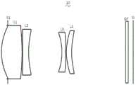
图1是本发明第一实施方式的摄像光学镜头的结构示意图;1 is a schematic structural diagram of an imaging optical lens according to a first embodiment of the present invention;
图2是图1所示摄像光学镜头的轴向像差示意图;Fig. 2 is the axial aberration schematic diagram of the imaging optical lens shown in Fig. 1;
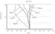
图3是图1所示摄像光学镜头的倍率色差示意图;3 is a schematic diagram of the magnification chromatic aberration of the imaging optical lens shown in FIG. 1;
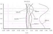
图4是图1所示摄像光学镜头的场曲及畸变示意图;4 is a schematic diagram of field curvature and distortion of the imaging optical lens shown in FIG. 1;
图5是本发明第二实施方式的摄像光学镜头的结构示意图;5 is a schematic structural diagram of an imaging optical lens according to a second embodiment of the present invention;
图6是图5所示摄像光学镜头的轴向像差示意图;Fig. 6 is the axial aberration schematic diagram of the imaging optical lens shown in Fig. 5;
图7是图5所示摄像光学镜头的倍率色差示意图;7 is a schematic diagram of the magnification chromatic aberration of the imaging optical lens shown in FIG. 5;
图8是图5所示摄像光学镜头的场曲及畸变示意图;FIG. 8 is a schematic diagram of field curvature and distortion of the imaging optical lens shown in FIG. 5;
图9是本发明第三实施方式的摄像光学镜头的结构示意图;9 is a schematic structural diagram of an imaging optical lens according to a third embodiment of the present invention;
图10是图9所示摄像光学镜头的轴向像差示意图;Fig. 10 is a schematic diagram of axial aberration of the imaging optical lens shown in Fig. 9;
图11是图9所示摄像光学镜头的倍率色差示意图;11 is a schematic diagram of the magnification chromatic aberration of the imaging optical lens shown in FIG. 9;
图12是图9所示摄像光学镜头的场曲及畸变示意图;Figure 12 is a schematic diagram of field curvature and distortion of the imaging optical lens shown in Figure 9;
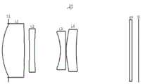
图13是本发明第四实施方式的摄像光学镜头的结构示意图;13 is a schematic structural diagram of an imaging optical lens according to a fourth embodiment of the present invention;
图14是图13所示摄像光学镜头的轴向像差示意图;Fig. 14 is a schematic diagram of axial aberration of the imaging optical lens shown in Fig. 13;
图15是图13所示摄像光学镜头的倍率色差示意图;15 is a schematic diagram of the magnification chromatic aberration of the imaging optical lens shown in FIG. 13;
图16是图13所示摄像光学镜头的场曲及畸变示意图。FIG. 16 is a schematic diagram of field curvature and distortion of the imaging optical lens shown in FIG. 13 .
具体实施方式Detailed ways
为使本发明的目的、技术方案和优点更加清楚,下面将结合附图对本发明的各实施方式进行详细的阐述。然而,本领域的普通技术人员可以理解,在本发明各实施方式中,为了使读者更好地理解本发明而提出了许多技术细节。但是,即使没有这些技术细节和基于以下各实施方式的种种变化和修改,也可以实现本发明所要求保护的技术方案。In order to make the objectives, technical solutions and advantages of the present invention clearer, each embodiment of the present invention will be described in detail below with reference to the accompanying drawings. However, those of ordinary skill in the art can appreciate that, in the various embodiments of the present invention, many technical details are set forth for the reader to better understand the present invention. However, even without these technical details and various changes and modifications based on the following embodiments, the technical solutions claimed in the present invention can be realized.
(第一实施方式)(first embodiment)
参考附图,本发明提供了一种摄像光学镜头10。图1所示为本发明第一实施方式的摄像光学镜头10,该摄像光学镜头10包括四个透镜。具体的,所述摄像光学镜头10,由物侧至像侧依序包括:光圈S1、第一透镜L1、第二透镜L2、第三透镜L3以及第四透镜L4。本实施方式中,优选的,在第四透镜L4和像面Si之间设置有玻璃平板GF等光学元件,其中玻璃平板GF可以是玻璃盖板,也可以是光学过滤片(filter),当然在其他可实施方式中,玻璃平板GF还可以设置在其他位置。Referring to the accompanying drawings, the present invention provides an imaging
本实施方式中,第一透镜L1具有正屈折力,第二透镜L2具有负屈折力,第三透镜L3具有负屈折力,第四透镜L4具有正屈折力。In this embodiment, the first lens L1 has a positive refractive power, the second lens L2 has a negative refractive power, the third lens L3 has a negative refractive power, and the fourth lens L4 has a positive refractive power.
在本实施方式中,第一透镜L1为塑料材质,第二透镜L2为塑料材质,第三透镜L3为塑料材质,第四透镜L4为塑料材质。In this embodiment, the first lens L1 is made of plastic material, the second lens L2 is made of plastic material, the third lens L3 is made of plastic material, and the fourth lens L4 is made of plastic material.
在此,定义第一透镜L1的阿贝数v1,第四透镜L4的阿贝数v4,摄像光学镜头10整体的焦距为f,第二透镜L2的焦距为f2,第三透镜L3的焦距为f3,第四透镜L4的物侧面的曲率半径为R7,第四透镜L4的像侧面的曲率半径为R8,第二透镜L2的像侧面到第三透镜L3的物侧面的轴上距离为d4,第三透镜L3的轴上厚度为d5,满足下列关系式:Here, the Abbe number v1 of the first lens L1 and the Abbe number v4 of the fourth lens L4 are defined, the focal length of the imaging
2.70≤v1/v4≤4.30 (1)2.70≤v1/v4≤4.30 (1)
-1.20≤f2/f≤-0.50 (2)-1.20≤f2/f≤-0.50 (2)
-0.80≤f3/f≤-0.30 (3)-0.80≤f3/f≤-0.30 (3)
-10.00≤(R7+R8)/(R7-R8)≤-2.00 (4)-10.00≤(R7+R8)/(R7-R8)≤-2.00 (4)
3.00≤d4/d5≤10.00 (5)3.00≤d4/d5≤10.00 (5)
关系式(1)规定了第一透镜L1和第四透镜L4色散系数的比值,在关系式范围内可以有效减小像差。The relational formula (1) specifies the ratio of the dispersion coefficients of the first lens L1 and the fourth lens L4, and the aberration can be effectively reduced within the range of the relational formula.
关系式(2)规定了第二透镜L2的焦距f2与系统总焦距f的比值,可以有效地平衡系统的球差以及场曲量。The relational formula (2) specifies the ratio of the focal length f2 of the second lens L2 to the total focal length f of the system, which can effectively balance the spherical aberration and field curvature of the system.
关系式(3)规定了第三透镜L3的焦距f3与系统总焦距f的比值,通过光焦度的合理分配,使得系统具有较佳的成像品质和较低的敏感性。The relational formula (3) specifies the ratio of the focal length f3 of the third lens L3 to the total focal length f of the system. Through the reasonable distribution of the focal power, the system has better imaging quality and lower sensitivity.
关系式(4)规定了第四透镜L4的形状,在关系式范围内时,随着超薄化的发展,有利于补正轴外画角的像差。The relational expression (4) specifies the shape of the fourth lens L4, and when the shape of the fourth lens L4 is within the range of the relational expression, it is beneficial to correct the aberration of the off-axis picture angle along with the progress of ultra-thinning.
关系式(5)规定了第二透镜L2像侧面和第三透镜L3物侧面之间的轴上距离d4与第三透镜L3的轴上厚度d5的比值,在关系式范围内,有助于压缩光学系统总长,实现超薄化效果。The relational expression (5) specifies the ratio of the on-axis distance d4 between the image side of the second lens L2 and the object side of the third lens L3 to the on-axis thickness d5 of the third lens L3. Within the range of the relational expression, it is helpful to compress The overall length of the optical system achieves ultra-thinning effect.
定义第二透镜L2的物侧面的曲率半径为R3,第二透镜L2的轴上厚度为d3,且满足下列关系式:R3/d3≤-15.00。该关系式规定了第二透镜L2的物侧面的曲率半径R3与第二透镜L2的轴上厚度d3的比值,在关系式范围内,有助于提高光学系统性能。The radius of curvature of the object side surface of the second lens L2 is defined as R3, the thickness on the axis of the second lens L2 is d3, and the following relationship is satisfied: R3/d3≤-15.00. This relational expression specifies the ratio of the curvature radius R3 of the object side surface of the second lens L2 to the on-axis thickness d3 of the second lens L2, and within the range of the relational expression, helps to improve the performance of the optical system.
定义第一透镜L1的物侧面的曲率半径为R1,第一透镜L1的像侧面的曲率半径为R2,且满足下列关系式:-1.00≤R1/R2≤0。该关系式规定了第一透镜L1的形状,在关系式范围内,可以缓和光线经过镜片的偏折程度,有效减小像差。The curvature radius of the object side surface of the first lens L1 is defined as R1, and the curvature radius of the image side surface of the first lens L1 is defined as R2, and the following relationship is satisfied: -1.00≤R1/R2≤0. The relational expression specifies the shape of the first lens L1, and within the range of the relational expression, the degree of deflection of light passing through the lens can be moderated, and aberrations can be effectively reduced.
本实施方式中,所述第一透镜L1的物侧面于近轴处为凸面,像侧面于近轴处为凸面。In this embodiment, the object side surface of the first lens L1 is convex at the paraxial position, and the image side surface is convex at the paraxial position.
摄像光学镜头10整体的焦距为f,定义第一透镜L1的焦距为f1,且满足下列关系式:0.19≤f1/f≤0.71。该关系式规定了第一透镜L1的焦距与系统总焦距f的比值,在规定的范围内,第一透镜L1具有适当的正屈折力,有利于减小系统像差,同时有利于镜头向超薄化发展。优选地,满足0.30≤f1/f≤0.57。The overall focal length of the imaging
第一透镜L1的物侧面的曲率半径为R1,第一透镜L1的像侧面的曲率半径为R2,且满足下列关系式:-1.98≤(R1+R2)/(R1-R2)≤0。合理控制第一透镜L1的形状,使得第一透镜L1能够有效地校正系统球差。优选地,满足-1.24≤(R1+R2)/(R1-R2)≤0。The curvature radius of the object side surface of the first lens L1 is R1, and the curvature radius of the image side surface of the first lens L1 is R2, and the following relationship is satisfied: -1.98≤(R1+R2)/(R1-R2)≤0. The shape of the first lens L1 is reasonably controlled, so that the first lens L1 can effectively correct the spherical aberration of the system. Preferably, -1.24≤(R1+R2)/(R1-R2)≤0 is satisfied.
定义第一透镜L1的轴上厚度为d1,摄像光学镜头10的光学总长为TTL,满足下列关系式:0.08≤d1/TTL≤0.25。在关系式范围内,有利于实现超薄化。优选地,满足0.12≤d1/TTL≤0.20。The axial thickness of the first lens L1 is defined as d1, and the optical total length of the imaging
本实施方式中,所述第二透镜L2的物侧面于近轴处为凹面,像侧面于近轴处为凹面。In this embodiment, the object side surface of the second lens L2 is concave at the paraxial position, and the image side surface is concave at the paraxial position.
定义第二透镜L2的物侧面的曲率半径为R3,第二透镜L2的像侧面的曲率半径为R4,满足下列关系式:-2.46≤(R3+R4)/(R3-R4)≤1.50。该关系式规定了第二透镜L2的形状,在关系式范围内时,随着镜头向超薄化发展,有利于补正轴上色像差问题。优选地,满足-1.54≤(R3+R4)/(R3-R4)≤1.20。The curvature radius of the object side surface of the second lens L2 is defined as R3, and the curvature radius of the image side surface of the second lens L2 is R4, which satisfies the following relationship: -2.46≤(R3+R4)/(R3-R4)≤1.50. This relational expression specifies the shape of the second lens L2, and within the range of the relational expression, as the lens becomes ultra-thin, it is beneficial to correct the problem of axial chromatic aberration. Preferably, -1.54≤(R3+R4)/(R3-R4)≤1.20 is satisfied.
摄像光学镜头10的光学总长为TTL,定义第二透镜L2的轴上厚度为d3,满足下列关系式:0.02≤d3/TTL≤0.10。在关系式范围内,有利于实现超薄化。优选地,满足0.03≤d3/TTL≤0.08。The total optical length of the imaging
本实施方式中,所述第三透镜L3的物侧面于近轴处为凹面,像侧面于近轴处为凸面。In this embodiment, the object side surface of the third lens L3 is concave at the paraxial position, and the image side surface is convex at the paraxial position.
定义第三透镜L3的物侧面的曲率半径为R5,第三透镜L3的像侧面的曲率半径为R6,满足下列关系式:-6.22≤(R5+R6)/(R5-R6)≤0.41。该关系式规定了第三透镜L3的形状,有利于第三透镜L3成型,在关系式规定范围内,可以缓和光线经过镜片的偏折程度,有效减小像差。优选地,满足-3.89≤(R5+R6)/(R5-R6)≤0.33。The curvature radius of the object side surface of the third lens L3 is defined as R5, and the curvature radius of the image side surface of the third lens L3 is R6, which satisfies the following relationship: -6.22≤(R5+R6)/(R5-R6)≤0.41. The relational formula specifies the shape of the third lens L3, which is beneficial to the shaping of the third lens L3. Within the range specified by the relational formula, the degree of deflection of the light passing through the lens can be eased, and aberrations can be effectively reduced. Preferably, -3.89≤(R5+R6)/(R5-R6)≤0.33 is satisfied.
第三透镜L3的轴上厚度为d5,摄像光学镜头10的光学总长为TTL,满足下列关系式:0.01≤d5/TTL≤0.07,在关系式范围内,有利于实现超薄化。优选地,满足0.02≤d5/TTL≤0.06。The axial thickness of the third lens L3 is d5, and the total optical length of the imaging
本实施方式中,所述第四透镜L4的物侧面于近轴处为凸面,像侧面于近轴处为凹面。In this embodiment, the object side surface of the fourth lens L4 is a convex surface at the paraxial position, and the image side surface is a concave surface at the paraxial position.
摄像光学镜头10整体的焦距为f,定义第四透镜L4的焦距为f4,满足下列关系式:0.24≤f4/f≤2.73,通过正光焦度的合理分配,使得系统具有较佳的成像品质和较低的敏感性。优选地,满足0.39≤f4/f≤2.18。The overall focal length of the imaging
摄像光学镜头10的光学总长为TTL,定义第四透镜L4的轴上厚度为d7,满足下列关系式:0.02≤d7/TTL≤0.11。在关系式范围内,有利于实现超薄化。优选地,0.03≤d7/TTL≤0.09。The total optical length of the imaging
本实施方式中,摄像光学镜头10整体的焦距为f,摄像光学镜头10的光学总长为TTL,满足下列关系式:f/TTL≥1.06,从而实现超薄化。本实施方式中,摄像光学镜头10整体的焦距为f,第一透镜L1与第二透镜L2的组合焦距为f12,满足下列关系式:0.33≤f12/f≤1.18。在关系式范围内,可消除摄像光学镜头10的像差与歪曲,且可压制摄像光学镜头10后焦距,维持影像镜片系统组小型化。优选地,满足0.52≤f12/f≤0.94。In this embodiment, the overall focal length of the imaging
当满足上述关系时,使得摄像光学镜头10具有良好光学性能的同时,能够满足长焦距和超薄化的设计要求;根据该光学镜头10的特性,该光学镜头10尤其适用于由高像素用的CCD、CMOS等摄像元件构成的手机摄像镜头组件和WEB摄像镜头。When the above relationship is satisfied, the imaging
下面将用实例进行说明本发明的摄像光学镜头10。各实例中所记载的符号如下所示。焦距、轴上距离、曲率半径、轴上厚度、反曲点位置、驻点位置的单位为mm。The imaging
TTL :光学总长(第一透镜L1的物侧面到像面Si的轴上距离),单位为mm。TTL: total optical length (the on-axis distance from the object side of the first lens L1 to the image plane Si), in mm.
光圈值FNO:是指摄像光学镜头的有效焦距和入瞳直径的比值。Aperture value FNO: refers to the ratio of the effective focal length of the imaging optical lens to the diameter of the entrance pupil.
优选地,透镜的物侧面和/或像侧面上还可以设置有反曲点和/或驻点,以满足高品质的成像需求,具体的可实施方案,参下所述。Preferably, an inflection point and/or a stagnation point may also be set on the object side and/or the image side of the lens, so as to meet the requirements of high-quality imaging. For specific implementations, see below.
表1示出本发明第一实施方式的摄像光学镜头10的设计数据。Table 1 shows design data of the imaging
【表1】【Table 1】

上表中各符号的含义如下。The meanings of the symbols in the above table are as follows.
R:透镜中心处的曲率半径;R: the radius of curvature at the center of the lens;
S1:光圈;S1: aperture;
R1:第一透镜L1的物侧面的曲率半径;R1: the radius of curvature of the object side surface of the first lens L1;
R2:第一透镜L1的像侧面的曲率半径;R2: the radius of curvature of the image side surface of the first lens L1;
R3:第二透镜L2的物侧面的曲率半径;R3: the radius of curvature of the object side surface of the second lens L2;
R4:第二透镜L2的像侧面的曲率半径;R4: the radius of curvature of the image side surface of the second lens L2;
R5:第三透镜L3的物侧面的曲率半径;R5: the radius of curvature of the object side surface of the third lens L3;
R6:第三透镜L3的像侧面的曲率半径;R6: the curvature radius of the image side surface of the third lens L3;
R7:第四透镜L4的物侧面的曲率半径;R7: the curvature radius of the object side surface of the fourth lens L4;
R8:第四透镜L4的像侧面的曲率半径;R8: the curvature radius of the image side surface of the fourth lens L4;
R9:玻璃平板GF的物侧面的曲率半径;R9: The curvature radius of the object side of the glass plate GF;
R10:玻璃平板GF的像侧面的曲率半径;R10: the curvature radius of the image side of the glass plate GF;
d:透镜的轴上厚度、透镜之间的轴上距离;d: the on-axis thickness of the lens, the on-axis distance between the lenses;
d0:光圈S1到第一透镜L1的物侧面的轴上距离;d0: the on-axis distance from the aperture S1 to the object side surface of the first lens L1;
d1:第一透镜L1的轴上厚度;d1: the on-axis thickness of the first lens L1;
d2:第一透镜L1的像侧面到第二透镜L2的物侧面的轴上距离;d2: the on-axis distance from the image side of the first lens L1 to the object side of the second lens L2;
d3:第二透镜L2的轴上厚度;d3: the on-axis thickness of the second lens L2;
d4:第二透镜L2的像侧面到第三透镜L3的物侧面的轴上距离;d4: the on-axis distance from the image side of the second lens L2 to the object side of the third lens L3;
d5:第三透镜L3的轴上厚度;d5: the on-axis thickness of the third lens L3;
d6:第三透镜L3的像侧面到第四透镜L4的物侧面的轴上距离;d6: the on-axis distance from the image side of the third lens L3 to the object side of the fourth lens L4;
d7:第四透镜L4的轴上厚度;d7: the on-axis thickness of the fourth lens L4;
d8:第四透镜L4的像侧面到光学过滤片GF的物侧面的轴上距离;d8: the on-axis distance from the image side of the fourth lens L4 to the object side of the optical filter GF;
d9:玻璃平板GF的轴上厚度;d9: On-axis thickness of glass plate GF;
d10:玻璃平板GF的像侧面到像面Si的轴上距离;d10: the axial distance from the image side of the glass plate GF to the image plane Si;
nd:d线的折射率(d线为波长为550nm的绿光);nd: the refractive index of the d line (the d line is green light with a wavelength of 550 nm);
nd1:第一透镜L1的d线的折射率;nd1: the refractive index of the d-line of the first lens L1;
nd2:第二透镜L2的d线的折射率;nd2: the refractive index of the d-line of the second lens L2;
nd3:第三透镜L3的d线的折射率;nd3: the refractive index of the d-line of the third lens L3;
nd4:第四透镜L4的d线的折射率;nd4: the refractive index of the d-line of the fourth lens L4;
ndg:玻璃平板GF的d线的折射率;ndg: the refractive index of the d-line of the glass plate GF;
vd: 阿贝数;vd: Abbe number;
v1:第一透镜L1的阿贝数;v1: Abbe number of the first lens L1;
v2:第二透镜L2的阿贝数;v2: Abbe number of the second lens L2;
v3:第三透镜L3的阿贝数;v3: Abbe number of the third lens L3;
v4:第四透镜L4的阿贝数;v4: Abbe number of the fourth lens L4;
vg:玻璃平板GF的阿贝数。vg: Abbe number of glass plate GF.
表2示出了本发明第一实施方式提供的摄像光学镜头10的各透镜的非球面数据。Table 2 shows the aspheric surface data of each lens of the imaging
【表2】【Table 2】

其中,k是圆锥系数,A4、A6、A8、A10、A12、A14、A16是非球面系数。Here, k is a conic coefficient, and A4, A6, A8, A10, A12, A14, and A16 are aspheric coefficients.
y=(x²/R)/{1+[1-(1+k)(x²/R²)]1/2}+A4x4+ A6x6+ A8x8+ A10x10+ A12x12+ A14x14+ A16x16 (6)y=(x²/R)/{1+[1-(1+k)(x²/R²)]1/2 }+A4x4 + A6x6 + A8x8 + A10x10 + A12x12 + A14x14 + A16x16 (6)
其中,x是非球面曲线上的点与光轴的垂直距离,y是非球面深度(非球面上距离光轴为x的点,与相切于非球面光轴上顶点的切面两者间的垂直距离)。Among them, x is the vertical distance between the point on the aspheric curve and the optical axis, and y is the depth of the aspheric surface (the vertical distance between the point on the aspheric surface whose distance is x from the optical axis and the tangent plane tangent to the vertex on the optical axis of the aspheric surface. ).
需要说明的是,本实施方式中各透镜的非球面优选的使用上述关系式(6)所示的非球面,但是,上述关系式(6)的具体形式仅为一个示例,实际上,并不限于关系式(6)中表示的非球面多项式形式。It should be noted that in the present embodiment, the aspherical surface of each lens is preferably the aspherical surface shown by the above-mentioned relational formula (6). Limited to the aspheric polynomial form expressed in relation (6).
表3示出本发明实施例的摄像光学镜头10中各透镜的反曲点设计数据。其中,P1R1、P1R2分别代表第一透镜L1的物侧面和像侧面,P2R1、P2R2分别代表第二透镜L2的物侧面和像侧面,P3R1、P3R2分别代表第三透镜L3的物侧面和像侧面,P4R1、P4R2分别代表第四透镜L4的物侧面和像侧面。“反曲点位置”栏位对应数据为各透镜表面所设置的反曲点到摄像光学镜头10光轴的垂直距离。Table 3 shows the design data of the inflection point of each lens in the imaging
【表3】【table 3】

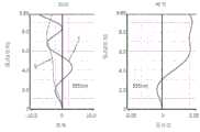
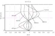
图2、图3分别示出了波长为650nm、610nm、555nm、510nm、470nm和430nm的光经过第一实施方式的摄像光学镜头10后的轴向像差以及倍率色差示意图。图4则示出了波长为555nm的光经过第一实施方式的摄像光学镜头10后的场曲及畸变示意图,图4的场曲S是弧矢方向的场曲,T是子午方向的场曲。2 and 3 respectively show schematic diagrams of axial aberration and chromatic aberration of magnification after light with wavelengths of 650 nm, 610 nm, 555 nm, 510 nm, 470 nm and 430 nm passes through the imaging
后出现的表16示出了各实例1、2、3、4中各种数值与关系式中已规定的参数所对应的值。The following Table 16 shows the values corresponding to the various numerical values in each of Examples 1, 2, 3, and 4 and the parameters specified in the relational expressions.
如表16所示,第一实施方式满足各关系式。As shown in Table 16, the first embodiment satisfies each relational expression.
在本实施方式中,所述摄像光学镜头10的入瞳直径ENPD为3.442mm,全视场像高IH为2.040mm,对角线方向的视场角FOV为19.60°,所述摄像光学镜头10满足长焦距和超薄化的设计要求,其轴上、轴外色像差被充分补正,且具有优秀的光学特征。In this embodiment, the entrance pupil diameter ENPD of the imaging
(第二实施方式)(Second Embodiment)
图5是第二实施方式中摄像光学镜头20的结构示意图,第二实施方式与第一实施方式基本相同,符号含义与第一实施方式相同,以下只列出不同点。5 is a schematic structural diagram of the imaging optical lens 20 in the second embodiment. The second embodiment is basically the same as the first embodiment, and the meanings of symbols are the same as those of the first embodiment, and only the differences are listed below.
在本实施方式中,第一透镜L1为玻璃材质,第二透镜L2为塑料材质,第三透镜L3为塑料材质,第四透镜L4为塑料材质。In this embodiment, the first lens L1 is made of glass, the second lens L2 is made of plastic, the third lens L3 is made of plastic, and the fourth lens L4 is made of plastic.
表4示出本发明第二实施方式的摄像光学镜头20的设计数据。Table 4 shows design data of the imaging optical lens 20 according to the second embodiment of the present invention.
【表4】【Table 4】

表5示出了本发明第二实施方式的摄像光学镜头20的各透镜的非球面数据。Table 5 shows aspherical surface data of each lens of the imaging optical lens 20 according to the second embodiment of the present invention.
【表5】【table 5】

表6、表7示出本发明实施例的摄像光学镜头20中各透镜的反曲点以及驻点设计数据。“驻点位置”栏位对应数据为各透镜表面所设置的驻点到摄像光学镜头20光轴的垂直距离。Table 6 and Table 7 show the design data of the inflection point and the stagnation point of each lens in the imaging optical lens 20 according to the embodiment of the present invention. The corresponding data in the column of "stagnation point position" is the vertical distance from the stagnation point set on the surface of each lens to the optical axis of the imaging optical lens 20 .
【表6】【Table 6】

【表7】【Table 7】

图6、图7分别示出了波长为650nm、610nm、555nm、510nm、470nm和430nm的光经过第二实施方式的摄像光学镜头20后的轴向像差以及倍率色差示意图。图8则示出了波长为555nm的光经过第二实施方式的摄像光学镜头20后的场曲及畸变示意图,图8的场曲S是弧矢方向的场曲,T是子午方向的场曲。6 and 7 respectively show schematic diagrams of axial aberration and chromatic aberration of magnification after light with wavelengths of 650 nm, 610 nm, 555 nm, 510 nm, 470 nm and 430 nm passes through the imaging optical lens 20 of the second embodiment. FIG. 8 shows a schematic diagram of the field curvature and distortion of light with a wavelength of 555 nm after passing through the imaging optical lens 20 of the second embodiment. The field curvature S in FIG. 8 is the field curvature in the sagittal direction, and T is the field curvature in the meridional direction. .
后出现的表16示出了各实例1、2、3、4中各种数值与关系式中已规定的参数所对应的值。The following Table 16 shows the values corresponding to the various numerical values in each of Examples 1, 2, 3, and 4 and the parameters specified in the relational expressions.
如表16所示,第二实施方式满足各关系式。As shown in Table 16, the second embodiment satisfies each relational expression.
在本实施方式中,所述摄像光学镜头20的入瞳直径ENPD为3.441mm,全视场像高IH为2.040mm,对角线方向的视场角FOV为19.59°,所述摄像光学镜头20满足长焦距和超薄化的设计要求,其轴上、轴外色像差被充分补正,且具有优秀的光学特征。In this embodiment, the entrance pupil diameter ENPD of the imaging optical lens 20 is 3.441 mm, the image height IH of the full field of view is 2.040 mm, and the FOV in the diagonal direction is 19.59°. The imaging optical lens 20 To meet the design requirements of long focal length and ultra-thin, its on-axis and off-axis chromatic aberrations are fully corrected, and it has excellent optical characteristics.
(第三实施方式)(third embodiment)
图9是第三实施方式中摄像光学镜头30的结构示意图,第三实施方式与第一实施方式基本相同。FIG. 9 is a schematic structural diagram of the imaging
表8示出了本发明第三实施方式的摄像光学镜头30的设计数据。Table 8 shows design data of the imaging
【表8】【Table 8】

表9示出了本发明第三实施方式的摄像光学镜头30的各透镜的非球面数据。Table 9 shows aspherical surface data of each lens of the imaging
【表9】【Table 9】

表10、表11示出本发明实施例的摄像光学镜头30中各透镜的反曲点以及驻点设计数据。“驻点位置”栏位对应数据为各透镜表面所设置的驻点到摄像光学镜头30光轴的垂直距离。Table 10 and Table 11 show the design data of the inflection point and stagnation point of each lens in the imaging
【表10】【Table 10】

【表11】【Table 11】

图10、图11分别示出了波长为650nm、610nm、555nm、510nm、470nm和430nm的光经过第三实施方式的摄像光学镜头30后的轴向像差以及倍率色差示意图。图12则示出了波长为555nm的光经过第三实施方式的摄像光学镜头30后的场曲及畸变示意图,图12的场曲S是弧矢方向的场曲,T是子午方向的场曲。10 and 11 respectively show schematic diagrams of axial aberration and chromatic aberration of magnification after light with wavelengths of 650 nm, 610 nm, 555 nm, 510 nm, 470 nm and 430 nm passes through the imaging
后出现的表16示出了各实例1、2、3、4中各种数值与关系式中已规定的参数所对应的值。The following Table 16 shows the values corresponding to the various numerical values in each of Examples 1, 2, 3, and 4 and the parameters specified in the relational expressions.
如表16所示,第三实施方式满足各关系式。As shown in Table 16, the third embodiment satisfies each relational expression.
在本实施方式中,所述摄像光学镜头30的入瞳直径ENPD为3.441mm,全视场像高IH为2.040mm,对角线方向的视场角FOV为19.77°,所述摄像光学镜头30满足长焦距和超薄化的设计要求,其轴上、轴外色像差被充分补正,且具有优秀的光学特征。In this embodiment, the entrance pupil diameter ENPD of the imaging
(第四实施方式)(Fourth Embodiment)
图13是第四实施方式中摄像光学镜头40的结构示意图,第四实施方式与第一实施方式基本相同,符号含义与第一实施方式相同,以下只列出不同点。13 is a schematic structural diagram of the imaging
其中,本实施方式中,第二透镜L2的像侧面于近轴处为凸面,第三透镜L3的像侧面于近轴处为凹面。In this embodiment, the image side surface of the second lens L2 is convex at the paraxial position, and the image side surface of the third lens L3 is concave at the paraxial position.
在本实施方式中,第一透镜L1为玻璃材质,第二透镜L2为塑料材质,第三透镜L3为塑料材质,第四透镜L4为塑料材质。In this embodiment, the first lens L1 is made of glass, the second lens L2 is made of plastic, the third lens L3 is made of plastic, and the fourth lens L4 is made of plastic.
表12示出了本发明第四实施方式的摄像光学镜头40的设计数据。Table 12 shows design data of the imaging
【表12】【Table 12】

表13示出了本发明第四实施方式的摄像光学镜头40的各透镜的非球面数据。Table 13 shows aspherical surface data of each lens of the imaging
【表13】【Table 13】

表14、表15示出本发明实施例的摄像光学镜头40中各透镜的反曲点以及驻点设计数据。“驻点位置”栏位对应数据为各透镜表面所设置的驻点到摄像光学镜头40光轴的垂直距离。Table 14 and Table 15 show the design data of the inflection point and stagnation point of each lens in the imaging
【表14】【Table 14】

【表15】【Table 15】

图14、图15分别示出了波长为650nm、610nm、555nm、510nm、470nm和430nm的光经过第四实施方式的摄像光学镜头40后的轴向像差以及倍率色差示意图。图16则示出了波长为555nm的光经过第四实施方式的摄像光学镜头40后的场曲及畸变示意图,图16的场曲S是弧矢方向的场曲,T是子午方向的场曲。14 and 15 respectively show schematic diagrams of axial aberration and chromatic aberration of magnification after light with wavelengths of 650 nm, 610 nm, 555 nm, 510 nm, 470 nm and 430 nm passes through the imaging
后出现的表16示出了各实例1、2、3、4中各种数值与关系式中已规定的参数所对应的值。The following Table 16 shows the values corresponding to the various numerical values in each of Examples 1, 2, 3, and 4 and the parameters specified in the relational expressions.
如表16所示,第四实施方式满足各关系式。As shown in Table 16, the fourth embodiment satisfies each relational expression.
在本实施方式中,所述摄像光学镜头30的入瞳直径ENPD为3.441mm,全视场像高IH为2.040mm,对角线方向的视场角FOV为19.42°,所述摄像光学镜头40满足长焦距和超薄化的设计要求,其轴上、轴外色像差被充分补正,且具有优秀的光学特征。In this embodiment, the entrance pupil diameter ENPD of the imaging
以下表16按照上述关系式列出了第一实施方式、第二实施方式、第三实施方式、第四实施方式中对应各关系式的数值,以及其他相关参数的取值。The following Table 16 lists the numerical values corresponding to the relational expressions in the first embodiment, the second embodiment, the third embodiment, and the fourth embodiment, and the values of other related parameters according to the above-mentioned relational expressions.
【表16】【Table 16】

本领域的普通技术人员可以理解,上述各实施方式是实现本发明的具体实施方式,而在实际应用中,可以在形式上和细节上对其作各种改变,而不偏离本发明的精神和范围。Those of ordinary skill in the art can understand that the above-mentioned embodiments are specific embodiments for realizing the present invention, and in practical applications, various changes can be made in form and details without departing from the spirit and the spirit of the present invention. scope.
Claims (9)
Priority Applications (4)
| Application Number | Priority Date | Filing Date | Title |
|---|---|---|---|
| CN202010458134.3ACN111367060B (en) | 2020-05-27 | 2020-05-27 | Camera optics |
| PCT/CN2020/094524WO2021237781A1 (en) | 2020-05-27 | 2020-06-05 | Camera optical lens |
| JP2020212687AJP7072629B2 (en) | 2020-05-27 | 2020-12-22 | Imaging optical lens |
| US17/131,777US20210373285A1 (en) | 2020-05-27 | 2020-12-23 | Camera optical lens |
Applications Claiming Priority (1)
| Application Number | Priority Date | Filing Date | Title |
|---|---|---|---|
| CN202010458134.3ACN111367060B (en) | 2020-05-27 | 2020-05-27 | Camera optics |
Publications (2)
| Publication Number | Publication Date |
|---|---|
| CN111367060A CN111367060A (en) | 2020-07-03 |
| CN111367060Btrue CN111367060B (en) | 2020-08-21 |
Family
ID=71205861
Family Applications (1)
| Application Number | Title | Priority Date | Filing Date |
|---|---|---|---|
| CN202010458134.3AActiveCN111367060B (en) | 2020-05-27 | 2020-05-27 | Camera optics |
Country Status (4)
| Country | Link |
|---|---|
| US (1) | US20210373285A1 (en) |
| JP (1) | JP7072629B2 (en) |
| CN (1) | CN111367060B (en) |
| WO (1) | WO2021237781A1 (en) |
Families Citing this family (13)
| Publication number | Priority date | Publication date | Assignee | Title |
|---|---|---|---|---|
| CN112882213B (en)* | 2021-01-20 | 2023-02-17 | 维沃移动通信有限公司 | Optical lens, camera module and electronic equipment |
| US20220326480A1 (en)* | 2021-04-06 | 2022-10-13 | Samsung Electro-Mechanics Co., Ltd. | Optical imaging system |
| CN113031227B (en)* | 2021-05-08 | 2024-11-15 | 浙江舜宇光学有限公司 | An optical imaging lens |
| CN113281880B (en)* | 2021-05-10 | 2022-08-23 | 江西晶超光学有限公司 | Imaging system, lens module and electronic equipment |
| CN113341539B (en)* | 2021-05-20 | 2022-08-30 | 江西晶超光学有限公司 | Optical system, lens module and electronic equipment |
| CN113671673B (en)* | 2021-09-18 | 2025-06-06 | 浙江舜宇光学有限公司 | An optical imaging lens |
| US12136615B2 (en)* | 2021-11-30 | 2024-11-05 | Qorvo Us, Inc. | Electronic package with interposer between integrated circuit dies |
| CN114114636B (en)* | 2021-12-13 | 2024-08-16 | 浙江舜宇光学有限公司 | Optical lens set |
| WO2023128625A1 (en)* | 2021-12-28 | 2023-07-06 | 삼성전자 주식회사 | Lens assembly and electronic device comprising same |
| CN114509862B (en)* | 2022-02-14 | 2023-07-04 | 江西晶超光学有限公司 | Optical system, camera module and electronic equipment |
| CN115407480B (en)* | 2022-05-18 | 2024-10-15 | 福建福光天瞳光学有限公司 | Lightweight security lens and imaging method thereof |
| WO2024258064A1 (en)* | 2023-06-13 | 2024-12-19 | 삼성전자 주식회사 | Imaging device and electronic device including same |
| CN119717220B (en)* | 2025-02-27 | 2025-05-09 | 云南汇恒光电技术有限公司 | Fixed focus lens |
Family Cites Families (12)
| Publication number | Priority date | Publication date | Assignee | Title |
|---|---|---|---|---|
| JP2008281873A (en)* | 2007-05-11 | 2008-11-20 | Sony Corp | Imaging lens |
| JP4947423B2 (en)* | 2007-08-29 | 2012-06-06 | コニカミノルタオプト株式会社 | Imaging lens |
| TWI395990B (en)* | 2009-05-11 | 2013-05-11 | Largan Precision Co Ltd | Optical lens system for taking image |
| TWI408409B (en)* | 2009-09-04 | 2013-09-11 | Largan Precision Co Ltd | Imaging lens assembly |
| TWI431355B (en)* | 2011-05-16 | 2014-03-21 | Largan Precision Co Ltd | Optical image lens assembly |
| US9223118B2 (en)* | 2013-10-31 | 2015-12-29 | Apple Inc. | Small form factor telephoto camera |
| KR102650547B1 (en)* | 2015-11-02 | 2024-03-26 | 삼성전자주식회사 | Optical lens assembly and apparatus having the same and method of forming an image |
| CN106154494B (en)* | 2016-03-18 | 2019-03-22 | 玉晶光电(厦门)有限公司 | Optical mirror slip group |
| CN106154515B (en)* | 2016-03-18 | 2019-02-01 | 玉晶光电(厦门)有限公司 | Optical mirror slip group |
| CN106154493B (en)* | 2016-03-18 | 2019-03-22 | 玉晶光电(厦门)有限公司 | Optical mirror slip group |
| CN105607233B (en)* | 2016-03-23 | 2018-09-07 | 浙江舜宇光学有限公司 | Telephoto lens |
| CN115016106B (en)* | 2017-05-03 | 2024-08-13 | 信泰光学(深圳)有限公司 | Imaging lens |
- 2020
- 2020-05-27CNCN202010458134.3Apatent/CN111367060B/enactiveActive
- 2020-06-05WOPCT/CN2020/094524patent/WO2021237781A1/ennot_activeCeased
- 2020-12-22JPJP2020212687Apatent/JP7072629B2/enactiveActive
- 2020-12-23USUS17/131,777patent/US20210373285A1/ennot_activeAbandoned
Also Published As
| Publication number | Publication date |
|---|---|
| WO2021237781A1 (en) | 2021-12-02 |
| JP2021189426A (en) | 2021-12-13 |
| CN111367060A (en) | 2020-07-03 |
| JP7072629B2 (en) | 2022-05-20 |
| US20210373285A1 (en) | 2021-12-02 |
Similar Documents
| Publication | Publication Date | Title |
|---|---|---|
| CN111367060B (en) | Camera optics | |
| CN111538142B (en) | Camera optics | |
| CN111538140B (en) | Image pickup optical lens | |
| CN111596445B (en) | Camera optics | |
| CN111624744B (en) | Camera optics | |
| CN111538141B (en) | Image pickup optical lens | |
| CN111427136B (en) | Image pickup optical lens | |
| CN111427135B (en) | Image pickup optical lens | |
| CN111474688B (en) | Image pickup optical lens | |
| CN111538138B (en) | Image pickup optical lens | |
| CN111399196B (en) | Image pickup optical lens | |
| CN110596859A (en) | camera optics | |
| CN111308650A (en) | Camera optics | |
| WO2022047985A1 (en) | Optical camera lens | |
| WO2022052258A1 (en) | Camera optical lens | |
| WO2022062072A1 (en) | Camera optical lens | |
| CN112684580B (en) | camera optics | |
| CN111736317B (en) | Camera optics | |
| WO2021031281A1 (en) | Photographing optical lens | |
| CN111736316B (en) | Camera optics | |
| WO2022088351A1 (en) | Optical camera lens | |
| WO2022047991A1 (en) | Optical camera lens | |
| CN111458851A (en) | Image pickup optical lens | |
| CN111505808B (en) | Image pickup optical lens | |
| WO2022062079A1 (en) | Camera optical lens |
Legal Events
| Date | Code | Title | Description |
|---|---|---|---|
| PB01 | Publication | ||
| PB01 | Publication | ||
| SE01 | Entry into force of request for substantive examination | ||
| SE01 | Entry into force of request for substantive examination | ||
| GR01 | Patent grant | ||
| GR01 | Patent grant | ||
| CP01 | Change in the name or title of a patent holder | ||
| CP01 | Change in the name or title of a patent holder | Address after:213000 Xinwei 1st Road, Changzhou Comprehensive Bonded Zone, Jiangsu Province Patentee after:Chengrui optics (Changzhou) Co.,Ltd. Address before:213000 Xinwei 1st Road, Changzhou Comprehensive Bonded Zone, Jiangsu Province Patentee before:Ruisheng Communication Technology (Changzhou) Co.,Ltd. | |
| CP03 | Change of name, title or address | ||
| CP03 | Change of name, title or address | Address after:213000 Xinwei 1st Road, Changzhou Comprehensive Bonded Zone, Jiangsu Province Patentee after:Chengrui Optics (Changzhou) Co.,Ltd. Country or region after:China Address before:Xinwei 1st Road, Comprehensive Bonded Zone, Changzhou City, Jiangsu Province Patentee before:Chengrui optics (Changzhou) Co.,Ltd. Country or region before:China |