CN111359165A - Parallel-drive lower limb rehabilitation training robot - Google Patents
Parallel-drive lower limb rehabilitation training robotDownload PDFInfo
- Publication number
- CN111359165A CN111359165ACN202010288689.8ACN202010288689ACN111359165ACN 111359165 ACN111359165 ACN 111359165ACN 202010288689 ACN202010288689 ACN 202010288689ACN 111359165 ACN111359165 ACN 111359165A
- Authority
- CN
- China
- Prior art keywords
- assembly
- cushion
- lower limb
- parallel
- lifting
- Prior art date
- Legal status (The legal status is an assumption and is not a legal conclusion. Google has not performed a legal analysis and makes no representation as to the accuracy of the status listed.)
- Granted
Links
- 210000003141lower extremityAnatomy0.000titleclaimsabstractdescription81
- 210000004394hip jointAnatomy0.000claimsdescription27
- 230000033001locomotionEffects0.000claimsdescription19
- 210000000689upper legAnatomy0.000claimsdescription17
- 210000003414extremityAnatomy0.000claimsdescription9
- 210000002683footAnatomy0.000claimsdescription4
- 230000036544postureEffects0.000abstractdescription20
- 230000000712assemblyEffects0.000abstractdescription15
- 238000000429assemblyMethods0.000abstractdescription15
- 238000000034methodMethods0.000abstractdescription9
- 230000009286beneficial effectEffects0.000abstractdescription8
- 230000006870functionEffects0.000abstractdescription7
- 230000008569processEffects0.000abstractdescription5
- 230000001815facial effectEffects0.000abstract1
- 238000009434installationMethods0.000description24
- 210000002414legAnatomy0.000description23
- 238000010586diagramMethods0.000description16
- 244000309466calfSpecies0.000description9
- 208000006011StrokeDiseases0.000description7
- 206010061296Motor dysfunctionDiseases0.000description4
- 230000001360synchronised effectEffects0.000description4
- 230000005540biological transmissionEffects0.000description3
- 230000008859changeEffects0.000description3
- 238000005516engineering processMethods0.000description2
- 238000011084recoveryMethods0.000description2
- 239000000758substrateSubstances0.000description2
- 229920000742CottonPolymers0.000description1
- 229910000831SteelInorganic materials0.000description1
- 208000027418Wounds and injuryDiseases0.000description1
- 230000009471actionEffects0.000description1
- 210000000544articulatio talocruralisAnatomy0.000description1
- 238000005452bendingMethods0.000description1
- 230000008602contractionEffects0.000description1
- 230000006378damageEffects0.000description1
- 230000000694effectsEffects0.000description1
- 239000006260foamSubstances0.000description1
- 210000001624hipAnatomy0.000description1
- 230000006872improvementEffects0.000description1
- 208000014674injuryDiseases0.000description1
- 210000000629knee jointAnatomy0.000description1
- 239000000463materialSubstances0.000description1
- 238000012986modificationMethods0.000description1
- 230000004048modificationEffects0.000description1
- 230000007659motor functionEffects0.000description1
- 239000007779soft materialSubstances0.000description1
- 239000010959steelSubstances0.000description1
- 238000006467substitution reactionMethods0.000description1
- 230000004083survival effectEffects0.000description1
- 210000001364upper extremityAnatomy0.000description1
- 238000003466weldingMethods0.000description1
Images


Classifications
- A—HUMAN NECESSITIES
- A63—SPORTS; GAMES; AMUSEMENTS
- A63B—APPARATUS FOR PHYSICAL TRAINING, GYMNASTICS, SWIMMING, CLIMBING, OR FENCING; BALL GAMES; TRAINING EQUIPMENT
- A63B23/00—Exercising apparatus specially adapted for particular parts of the body
- A63B23/035—Exercising apparatus specially adapted for particular parts of the body for limbs, i.e. upper or lower limbs, e.g. simultaneously
- A63B23/04—Exercising apparatus specially adapted for particular parts of the body for limbs, i.e. upper or lower limbs, e.g. simultaneously for lower limbs
- A63B23/0405—Exercising apparatus specially adapted for particular parts of the body for limbs, i.e. upper or lower limbs, e.g. simultaneously for lower limbs involving a bending of the knee and hip joints simultaneously
- A—HUMAN NECESSITIES
- A61—MEDICAL OR VETERINARY SCIENCE; HYGIENE
- A61H—PHYSICAL THERAPY APPARATUS, e.g. DEVICES FOR LOCATING OR STIMULATING REFLEX POINTS IN THE BODY; ARTIFICIAL RESPIRATION; MASSAGE; BATHING DEVICES FOR SPECIAL THERAPEUTIC OR HYGIENIC PURPOSES OR SPECIFIC PARTS OF THE BODY
- A61H1/00—Apparatus for passive exercising; Vibrating apparatus; Chiropractic devices, e.g. body impacting devices, external devices for briefly extending or aligning unbroken bones
- A61H1/02—Stretching or bending or torsioning apparatus for exercising
- A61H1/0237—Stretching or bending or torsioning apparatus for exercising for the lower limbs
- A61H1/0255—Both knee and hip of a patient, e.g. in supine or sitting position, the feet being moved together in a plane substantially parallel to the body-symmetrical plane
- A61H1/0262—Walking movement; Appliances for aiding disabled persons to walk
- A—HUMAN NECESSITIES
- A63—SPORTS; GAMES; AMUSEMENTS
- A63B—APPARATUS FOR PHYSICAL TRAINING, GYMNASTICS, SWIMMING, CLIMBING, OR FENCING; BALL GAMES; TRAINING EQUIPMENT
- A63B21/00—Exercising apparatus for developing or strengthening the muscles or joints of the body by working against a counterforce, with or without measuring devices
- A63B21/00181—Exercising apparatus for developing or strengthening the muscles or joints of the body by working against a counterforce, with or without measuring devices comprising additional means assisting the user to overcome part of the resisting force, i.e. assisted-active exercising
- A—HUMAN NECESSITIES
- A63—SPORTS; GAMES; AMUSEMENTS
- A63B—APPARATUS FOR PHYSICAL TRAINING, GYMNASTICS, SWIMMING, CLIMBING, OR FENCING; BALL GAMES; TRAINING EQUIPMENT
- A63B22/00—Exercising apparatus specially adapted for conditioning the cardio-vascular system, for training agility or co-ordination of movements
- A63B22/02—Exercising apparatus specially adapted for conditioning the cardio-vascular system, for training agility or co-ordination of movements with movable endless bands, e.g. treadmills
- A—HUMAN NECESSITIES
- A61—MEDICAL OR VETERINARY SCIENCE; HYGIENE
- A61H—PHYSICAL THERAPY APPARATUS, e.g. DEVICES FOR LOCATING OR STIMULATING REFLEX POINTS IN THE BODY; ARTIFICIAL RESPIRATION; MASSAGE; BATHING DEVICES FOR SPECIAL THERAPEUTIC OR HYGIENIC PURPOSES OR SPECIFIC PARTS OF THE BODY
- A61H2201/00—Characteristics of apparatus not provided for in the preceding codes
- A61H2201/16—Physical interface with patient
- A61H2201/1602—Physical interface with patient kind of interface, e.g. head rest, knee support or lumbar support
- A61H2201/164—Feet or leg, e.g. pedal
- A61H2201/1642—Holding means therefor
- A—HUMAN NECESSITIES
- A61—MEDICAL OR VETERINARY SCIENCE; HYGIENE
- A61H—PHYSICAL THERAPY APPARATUS, e.g. DEVICES FOR LOCATING OR STIMULATING REFLEX POINTS IN THE BODY; ARTIFICIAL RESPIRATION; MASSAGE; BATHING DEVICES FOR SPECIAL THERAPEUTIC OR HYGIENIC PURPOSES OR SPECIFIC PARTS OF THE BODY
- A61H2201/00—Characteristics of apparatus not provided for in the preceding codes
- A61H2201/50—Control means thereof
- A61H2201/5058—Sensors or detectors
- A61H2201/5064—Position sensors
- A—HUMAN NECESSITIES
- A61—MEDICAL OR VETERINARY SCIENCE; HYGIENE
- A61H—PHYSICAL THERAPY APPARATUS, e.g. DEVICES FOR LOCATING OR STIMULATING REFLEX POINTS IN THE BODY; ARTIFICIAL RESPIRATION; MASSAGE; BATHING DEVICES FOR SPECIAL THERAPEUTIC OR HYGIENIC PURPOSES OR SPECIFIC PARTS OF THE BODY
- A61H2201/00—Characteristics of apparatus not provided for in the preceding codes
- A61H2201/50—Control means thereof
- A61H2201/5058—Sensors or detectors
- A61H2201/5071—Pressure sensors
- A—HUMAN NECESSITIES
- A61—MEDICAL OR VETERINARY SCIENCE; HYGIENE
- A61H—PHYSICAL THERAPY APPARATUS, e.g. DEVICES FOR LOCATING OR STIMULATING REFLEX POINTS IN THE BODY; ARTIFICIAL RESPIRATION; MASSAGE; BATHING DEVICES FOR SPECIAL THERAPEUTIC OR HYGIENIC PURPOSES OR SPECIFIC PARTS OF THE BODY
- A61H2203/00—Additional characteristics concerning the patient
- A61H2203/04—Position of the patient
- A61H2203/0406—Standing on the feet
- A—HUMAN NECESSITIES
- A61—MEDICAL OR VETERINARY SCIENCE; HYGIENE
- A61H—PHYSICAL THERAPY APPARATUS, e.g. DEVICES FOR LOCATING OR STIMULATING REFLEX POINTS IN THE BODY; ARTIFICIAL RESPIRATION; MASSAGE; BATHING DEVICES FOR SPECIAL THERAPEUTIC OR HYGIENIC PURPOSES OR SPECIFIC PARTS OF THE BODY
- A61H2203/00—Additional characteristics concerning the patient
- A61H2203/04—Position of the patient
- A61H2203/0443—Position of the patient substantially horizontal
- A61H2203/0456—Supine
- A—HUMAN NECESSITIES
- A63—SPORTS; GAMES; AMUSEMENTS
- A63B—APPARATUS FOR PHYSICAL TRAINING, GYMNASTICS, SWIMMING, CLIMBING, OR FENCING; BALL GAMES; TRAINING EQUIPMENT
- A63B2208/00—Characteristics or parameters related to the user or player
- A63B2208/02—Characteristics or parameters related to the user or player posture
- A63B2208/0204—Standing on the feet
- A—HUMAN NECESSITIES
- A63—SPORTS; GAMES; AMUSEMENTS
- A63B—APPARATUS FOR PHYSICAL TRAINING, GYMNASTICS, SWIMMING, CLIMBING, OR FENCING; BALL GAMES; TRAINING EQUIPMENT
- A63B2208/00—Characteristics or parameters related to the user or player
- A63B2208/02—Characteristics or parameters related to the user or player posture
- A63B2208/0242—Lying down
- A63B2208/0252—Lying down supine
- A—HUMAN NECESSITIES
- A63—SPORTS; GAMES; AMUSEMENTS
- A63B—APPARATUS FOR PHYSICAL TRAINING, GYMNASTICS, SWIMMING, CLIMBING, OR FENCING; BALL GAMES; TRAINING EQUIPMENT
- A63B2220/00—Measuring of physical parameters relating to sporting activity
- A63B2220/10—Positions
- A—HUMAN NECESSITIES
- A63—SPORTS; GAMES; AMUSEMENTS
- A63B—APPARATUS FOR PHYSICAL TRAINING, GYMNASTICS, SWIMMING, CLIMBING, OR FENCING; BALL GAMES; TRAINING EQUIPMENT
- A63B2220/00—Measuring of physical parameters relating to sporting activity
- A63B2220/50—Force related parameters
- A63B2220/56—Pressure
Landscapes
- Health & Medical Sciences (AREA)
- General Health & Medical Sciences (AREA)
- Physical Education & Sports Medicine (AREA)
- Orthopedic Medicine & Surgery (AREA)
- Life Sciences & Earth Sciences (AREA)
- Rehabilitation Therapy (AREA)
- Pain & Pain Management (AREA)
- Epidemiology (AREA)
- Animal Behavior & Ethology (AREA)
- Public Health (AREA)
- Veterinary Medicine (AREA)
- Biophysics (AREA)
- Cardiology (AREA)
- Vascular Medicine (AREA)
- Rehabilitation Tools (AREA)
Abstract
Translated fromChinese
Description
Translated fromChinese技术领域technical field
本发明涉及一种下肢康复训练技术领域,具体涉及一种并联驱动下肢康复训练机器人。The invention relates to the technical field of lower limb rehabilitation training, in particular to a parallel drive lower limb rehabilitation training robot.
背景技术Background technique
脑卒中是导致残疾的主要原因之一。随着医疗护理及医疗技术的提高,脑卒中后患者的存活率越来越高,而这同时提高了脑卒中的致残率。其中,肢体运动功能障碍增加了脑卒中后患者及家庭的沉重负担,严重影响患者的日常生活。因此,如何有效提高脑卒中后患者步行能力及日常生活活动能力,成为脑卒中康复研究的主要目标。Stroke is one of the leading causes of disability. With the improvement of medical care and medical technology, the survival rate of patients after stroke is getting higher and higher, and this also increases the disability rate of stroke. Among them, limb motor dysfunction increases the heavy burden on patients and families after stroke, and seriously affects the daily life of patients. Therefore, how to effectively improve the walking ability and activities of daily living of post-stroke patients has become the main goal of stroke rehabilitation research.
基于神经康复理论,脑卒中后患者可以通过专业康复训练来恢复肢体功能;故需要一种下肢康复训练设备应用于下肢运动功能障碍者;该设备主要针对下肢有运动功能障碍的患者,主要作用是帮助有下肢运动功能障碍的患者完成各种运动功能康复训练过程,目前还未有辅助相关患者进行康复训练的设备。Based on the theory of neurorehabilitation, post-stroke patients can recover limb function through professional rehabilitation training; therefore, a lower limb rehabilitation training equipment is needed for those with lower limb motor dysfunction; this equipment is mainly aimed at patients with lower limb motor dysfunction, and its main function is to Help patients with lower extremity motor dysfunction to complete various motor function rehabilitation training process. At present, there is no equipment to assist related patients in rehabilitation training.
因此,基于以上问题,需要一种并联驱动下肢康复训练机器人,该机器人可适应于患者的躺卧以及站立模式的康复训练,可综合性帮助患者进行康复训练。Therefore, based on the above problems, there is a need for a parallel-driven lower limb rehabilitation training robot, which can be adapted to the rehabilitation training of the patient in the lying and standing modes, and can comprehensively assist the patient in the rehabilitation training.
发明内容SUMMARY OF THE INVENTION
有鉴于此,本发明提供一种并联驱动下肢康复训练机器人,该机器人可适应于患者的躺卧以及站立模式的康复训练,可综合性帮助患者进行康复训练。In view of this, the present invention provides a parallel-driven lower limb rehabilitation training robot, which can be adapted to the rehabilitation training of the patient in the lying and standing modes, and can comprehensively assist the patient in the rehabilitation training.
本发明的并联驱动下肢康复训练机器人,包括靠垫组件、连接于靠垫组件上用于分别固定患者腿部的一对下肢托架组件以及连接于靠垫组件和下肢托架组件上用于改变二者姿态以形成躺卧状态和站立状态的变形组件,所述变形组件包括升降组件、靠垫驱动组件以及下肢托架驱动组件,所述升降组件连接于靠垫组件下方,靠垫组件以可纵向摆动的方式安装于升降组件上,靠垫驱动组件连接于升降组件上用于驱动靠垫组件转动,所述下肢托架驱动组件连接于下肢托架上用于驱动下肢托架组件运动从而带动患者腿部运动。The parallel-driven lower limb rehabilitation training robot of the present invention includes a cushion assembly, a pair of lower limb bracket assemblies connected to the cushion assembly for fixing the patient's legs respectively, and a pair of lower limb bracket assemblies connected to the cushion assembly and the lower limb bracket assembly for changing the postures of the two. To form a deformation assembly in a lying state and a standing state, the deformation assembly includes a lifting assembly, a cushion driving assembly and a lower limb bracket driving assembly, the lifting assembly is connected below the cushion assembly, and the cushion assembly is longitudinally swingable. On the lifting assembly, the cushion driving assembly is connected to the lifting assembly for driving the cushion assembly to rotate, and the lower limb bracket driving assembly is connected to the lower limb bracket for driving the lower limb bracket assembly to move so as to drive the patient's legs to move.
进一步,所述变形组件还包括并联平台组件,所述并联平台组件包括与升降组件并联连接实现联动升降的并联支架以及连接于并联支架上的支撑平台,所述下肢托架驱动组件固定于支撑平台上,下肢托架驱动组件输出端与下肢托架组件可拆卸连接。Further, the deformation assembly further includes a parallel platform assembly, the parallel platform assembly includes a parallel support connected in parallel with the lifting assembly to realize linkage lifting and a support platform connected to the parallel support, and the lower limb bracket drive assembly is fixed to the support platform. The output ends of the upper and lower limb bracket drive assemblies are detachably connected to the lower limb bracket assembly.
进一步,所述下肢托架组件包括大腿支撑杆、与大腿支撑杆底端转动配合的小腿支撑杆、转动配合于小腿支撑杆底端的足部支撑托架以及连接于大腿支撑杆和小腿支撑杆上的绑缚件,所述大腿支撑杆顶部通过髋关节与靠垫组件连接。Further, the lower limb bracket assembly includes a thigh support rod, a calf support rod rotatably matched with the bottom end of the thigh support rod, a foot support bracket rotatably matched with the bottom end of the calf support rod, and connected to the thigh support rod and the calf support rod. The top of the thigh support rod is connected with the cushion assembly through the hip joint.
进一步,所述靠垫组件包括靠垫、连接于靠垫横向两侧的扶手以及固定于靠垫上的头枕。Further, the backrest assembly includes a backrest, armrests connected to both lateral sides of the backrest, and a headrest fixed on the backrest.
进一步,所述升降组件包括底部横架、顶部横架、连接于底部横架以及顶部横架之间横向排列设置的至少两个剪刀式升降结构,所述剪刀式升降结构包括相互交叉且中部转动配合的两个升降杆、纵向转动配合于底部横架上的升降螺杆以及与升降螺杆螺纹连接的升降滑块,两个升降杆的顶部与顶部横架转动配合,其中一个升降杆的底部与底部横架转动配合,另一个升降杆的底部与升降滑块转动配合,所述靠垫以可纵向摆动的方式与顶部横架转动配合。Further, the lift assembly includes a bottom cross frame, a top cross frame, at least two scissor lift structures connected to the bottom cross frame and horizontally arranged between the top cross frames. The two matching lifting rods, the lifting screw that is longitudinally rotated and matched with the bottom horizontal frame, and the lifting slider threadedly connected with the lifting screw, the top of the two lifting rods are rotated and matched with the top horizontal frame, and the bottom of one lifting rod is connected to the bottom. The horizontal frame is rotatably matched, the bottom of the other lifting rod is rotatably matched with the lifting slider, and the back cushion is rotatably matched with the top horizontal frame in a longitudinally swingable manner.
进一步,靠垫驱动组件包括横向连接于顶部横架并与顶部横架纵向转动配合的安装架、连接于安装架上的靠垫驱动杆以及安装于安装架上用于驱动靠垫驱动杆轴向运动的靠垫驱动件,所述靠垫驱动杆头部转动配合连接于靠垫上。Further, the backrest drive assembly includes a mounting frame that is laterally connected to the top cross frame and is longitudinally rotatably matched with the top cross frame, a back cushion driving rod connected to the mounting frame, and a back cushion mounted on the mounting frame for driving the backrest driving rod to move axially. A driving part, the head of the backrest driving rod is rotatably connected to the backrest.
进一步,所述下肢托架驱动组件包括至少两个驱动杆组件,所述驱动杆组件包括以可水平转动的方式连接于支撑平台上的底座以及伸缩驱动组件,所述伸缩驱动组件以可垂直于水平面摆动的方式与底座转动配合,所述驱动组件的输出端通过球面副连接于上平台,所述上平台与下肢托架组件可拆卸连接。Further, the lower limb bracket drive assembly includes at least two drive rod assemblies, the drive rod assemblies include a base connected to the support platform in a horizontally rotatable manner, and a telescopic drive assembly, the telescopic drive assembly can be perpendicular to The horizontal plane swings with the base in rotation, the output end of the drive assembly is connected to the upper platform through a spherical pair, and the upper platform is detachably connected to the lower limb bracket assembly.
进一步,所述髋关节包括以可纵向转动的方式与靠垫组件连接的转动板、与转动板偏心转动配合的髋关节支架以及与髋关节支架通过球面副配合的拖杆,所述大腿支撑杆端部与拖杆转动配合。Further, the hip joint includes a rotating plate connected with the cushion assembly in a longitudinally rotatable manner, a hip joint bracket eccentrically rotatably matched with the rotating plate, and a tow bar matched with the hip joint bracket through a spherical pair. The part is rotatably matched with the tow bar.
进一步,所述底部横架上安装有履带组件,所述履带组件用于在站立状态时支撑患者以实现患者的行走康复训练。Further, a crawler track assembly is installed on the bottom cross frame, and the crawler track assembly is used to support the patient in a standing state so as to realize the walking rehabilitation training of the patient.
进一步,所述并联支架包括连接于升降组件底部与支撑平台之间的若干根平行的并联摆杆以及连接于其中一个并联摆杆与靠垫组件之间的连动杆,所述并联摆杆两端分别与升降组件底部以及支撑平台转动配合,所述连动杆两端分别与其中一个并联摆杆以及靠垫组件转动配合。Further, the parallel support includes several parallel parallel swing rods connected between the bottom of the lifting assembly and the support platform, and a linkage rod connected between one of the parallel swing rods and the cushion assembly. Both ends of the parallel swing rod They are respectively rotatably matched with the bottom of the lifting assembly and the support platform, and the two ends of the linkage rod are respectively rotatably matched with one of the parallel swing rods and the backrest assembly.
本发明的有益效果:Beneficial effects of the present invention:
本发明的机器人具有躺卧和站立两种训练模式,能适用于患者康复初期在躺卧状态下的下肢康复训练,也能适用于患者恢复部分腿部功能的康复中后期在站立状态下的康复训练,可用于患者整个康复周期内的康复训练,综合辅助患者康复,同时通过变形组件的驱动形变利于辅助患者在躺卧和站立姿态的切换,靠垫组件的角度调节利于调节患者的背部姿态,以调节躺卧或者站立时对背部的支撑,利于患者在康复训练过程中背部姿态的调整,改善由于同一姿态长时间保持造成的疲劳,提高患者使用舒适度。The robot of the invention has two training modes of lying down and standing, which can be applied to the rehabilitation training of the lower limbs in the lying state in the initial stage of the patient's recovery, and can also be applied to the rehabilitation of the patient in the standing state in the middle and later stages of the rehabilitation of part of the leg function. It can be used for rehabilitation training in the entire rehabilitation cycle of the patient, comprehensively assisting the patient's rehabilitation, and at the same time, the driving deformation of the deformation component is conducive to assisting the patient to switch between lying and standing postures, and the angle adjustment of the cushion component is conducive to adjusting the patient's back posture to Adjusting the support of the back when lying down or standing is conducive to the adjustment of the patient's back posture during the rehabilitation training process, improving the fatigue caused by maintaining the same posture for a long time, and improving the comfort of the patient.
本发明的变形组件可实现靠垫的变形进行改变整个机器人的姿态,其中升降组件可带动靠垫组件升降进而调节靠垫组件的高度以适配站立和躺卧时患者的背部高度,同时靠垫驱动组件可驱动靠垫组件转动以在躺卧状态时保持水平、在站立状态时保持竖直、或者呈倾斜状态以调整患者的躺姿,通过调节靠垫组件可适配患者站立和躺卧时的背部姿态。The deformation assembly of the present invention can realize the deformation of the cushion to change the posture of the entire robot, wherein the lifting assembly can drive the cushion assembly to rise and fall to adjust the height of the cushion assembly to suit the height of the patient's back when standing and lying down, and the cushion driving assembly can drive the The backrest assembly is rotated to keep horizontal when lying down, vertical when standing, or tilted to adjust the patient's lying position. By adjusting the backrest assembly, the back posture of the patient when standing and lying down can be adapted.
附图说明Description of drawings
下面结合附图和实施例对本发明作进一步描述。The present invention will be further described below with reference to the accompanying drawings and embodiments.
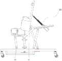
图1为本发明躺卧状态结构示意图;Fig. 1 is the structure schematic diagram of the lying state of the present invention;
图2为躺卧状态的侧视结构示意图;Fig. 2 is the side view structure schematic diagram of the lying state;
图3为本发明站立状态结构示意图;3 is a schematic structural diagram of the standing state of the present invention;
图4为站立状态侧视结构示意图;Fig. 4 is the side view structure schematic diagram of standing state;
图5为髋关节结构示意图;Figure 5 is a schematic diagram of the structure of the hip joint;
图6为靠垫驱动组件结构示意图;Figure 6 is a schematic structural diagram of a cushion drive assembly;
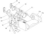
图7为局部结构示意图;7 is a schematic diagram of a partial structure;
图8为升降滑块结构示意图;Figure 8 is a schematic diagram of the structure of the lifting slider;
具体实施方式Detailed ways
图1为本发明躺卧状态结构示意图;图2为躺卧状态的侧视结构示意图;图3为本发明站立状态结构示意图;图4为站立状态侧视结构示意图;图5为髋关节结构示意图;图6为靠垫驱动组件结构示意图;图7为局部结构示意图;图8为升降滑块结构示意图;Fig. 1 is the structure schematic diagram of the lying state of the present invention; Fig. 2 is the side view structure schematic diagram of the lying state; Fig. 3 is the standing state structure schematic diagram of the present invention; Fig. 4 is the standing state side view structure schematic diagram; Fig. 5 is the hip joint structure schematic diagram ; Figure 6 is a schematic structural diagram of the cushion drive assembly; Figure 7 is a schematic diagram of a partial structure; Figure 8 is a schematic structural diagram of the lifting slider;
如图所示:本实施例提供了一种并联驱动下肢康复训练机器人,包括靠垫组件10、连接于靠垫组件上用于分别固定患者腿部的一对下肢托架组件20以及连接于靠垫组件和下肢托架组件上用于改变二者姿态以形成躺卧状态和站立状态的变形组件,所述变形组件包括升降组件30、靠垫驱动组件40以及下肢托架驱动组件50,所述升降组件30连接于靠垫组件10下方,靠垫组件10以可纵向摆动的方式安装于升降组件30上,靠垫驱动组件40连接于升降组件上用于驱动靠垫组件转动,所述下肢托架驱动组件50连接于下肢托架上用于驱动下肢托架组件20运动从而带动患者腿部运动。纵向为长度方向,横向对应于宽度方向,患者躺于训练机器人上时,纵向对应于患者的身高方向,横向对应于患者的宽度方向,前侧为患者躺于机器人上时,机器人纵向靠近患者头部一侧;纵向摆动含义为以横向轴线为中心轴摆动,即在纵向方向所在平面内摆动,横向转动含义为以纵向轴线为中心轴转动,即在横向方向所在平面内转动;结合图1和图3所示,靠垫组件用于支撑患者,在躺卧状态时,患者躺在靠垫组件上,在站立状态时,患者背靠在靠垫组件上,通过靠垫组件为患者提高良好的支撑。下肢托架组件连接于靠垫组件底部用于固定患者腿部,在躺卧状态时,下肢托架组件近似水平,并通过下肢托架驱动组件驱动下肢托架运动,可使得下肢托架摆动、扭动或者模仿患者走路的姿态,进而带动患者腿部康复运动,在站立状态时,同样可通过下肢托架带动患者腿部进行康复训练,或者在患者腿部恢复一定行动功能的前提下,可解除下肢托架驱动组件驱动的驱动功能,使得患者自行发力实现康复训练。变形组件可实现机器人的变形进行改变整个机器人的姿态,其中升降组件30可带动靠垫组件升降进而调节靠垫组件的高度以适配站立和躺卧时患者的背部高度,同时靠垫驱动组件可驱动靠垫组件转动以在躺卧状态时保持水平、在站立状态时保持竖直、或者呈倾斜状态以调整患者的躺姿,通过调节靠垫组件可适配患者站立和躺卧时的背部姿态,其中下肢托架组件20可转动配合安装于靠垫组件上或者可刚性连接于靠垫组件上以使得靠垫组件在改变姿态时可相应的改变姿态以适配患者的腿部;该机器人具有躺卧和站立两种训练模式,能适用于患者康复初期在躺卧状态下的下肢康复训练,也能适用于患者恢复部分腿部功能的康复中后期在站立状态下的康复训练,适用于患者整个康复周期内的康复训练,综合辅助患者康复,同时通过变形组件的驱动形变利于辅助患者在躺卧和站立姿态的切换,靠垫组件的角度调节利于调节患者的背部姿态,以调节躺卧或者站立时对背部的支撑,利于患者在康复训练过程中背部姿态的调整,改善由于同一姿态长时间保持造成的疲劳,提高患者使用舒适度。As shown in the figure: this embodiment provides a parallel-driven lower limb rehabilitation training robot, including a
本实施例中,所述升降组件30包括底部横架32、顶部横架31、连接于底部横架以及顶部横架之间横向排列设置的至少两个剪刀式升降结构,所述剪刀式升降结构包括相互交叉且中部转动配合的两个升降杆33、纵向转动配合于底部横架上的升降螺杆34以及与升降螺杆螺纹连接的升降滑块35,两个升降杆的顶部与顶部横架转动配合,其中一个升降杆的底部与底部横架转动配合,另一个升降杆的底部与升降滑块转动配合,所述靠垫以可纵向摆动的方式与顶部横架转动配合。底部横架32为下肢康复训练机器人最底层部分,所述底部横架32为H型结构,所述底部横架四角处安装有四个万向滚轮36,该万向滚轮应带制动系统,以便于保持机器人的状态,带有制动系统的万向滚轮为现有技术,具体不再赘述,万象滚轮可通过调平螺杆连接于底部横架上,通过调平螺杆可使下肢康复训练机器人平台在不平地面上保持水平,提高对地形的适应能力。顶部横架为矩形方框结构,底部横架32的两个纵梁与顶部横架31两个纵梁竖向相对,在两对竖向相对的纵梁之间各连接一套剪刀式升降结构,在底部横架32两个纵梁内侧各安装一个纵向延伸的升降螺杆,具体为底部横架32纵梁内侧向内突出形成两个螺杆安装座37,螺杆安装座37同时也是轴承座,升降螺杆两端通过轴承转动配合安装于该螺杆安装座上。结合图8所示,升降滑块35包括与升降螺杆螺纹配合的升降螺母35a、与底部横架32纵梁滑动配合的辅助滑块35b以及连接于升降螺母和辅助滑块的滑动台35c,其中底部横架32纵梁为矩形结构,滑动台35c为槽钢结构,滑动台35c扣于底部横架32纵梁上并可纵向滑动,该结构的升降滑块35其运动稳定性好,剪刀式升降结构中两个升降杆顶端转动配合于顶部横架31的纵梁上,其中一个升降杆底端转动配合于底部横架32的纵梁上,另一个升降杆底端转动配合于滑动台35c上,通过转动升降螺杆进而驱动升降螺母的纵向滑动带动两个剪刀式的升降杆摆动实现升降,其中升降螺杆可人工驱动转动或者可通过升降驱动结构进行驱动,本实施例中增设有升降驱动结构,其中升降驱动结构可以为两个电机分别与两个升降螺杆传动配合进行独立驱动,也可以通过一个电机并通过齿轮传动系或者皮带轮传动系同时驱动两个升降螺杆转动,本实施例中采用一个电机配合皮带轮传动系实现两个升降螺杆的同步转动,升降驱动件与靠垫驱动组件40的结构类似,此处不再赘述;该结构的升降组件配合剪刀式的升降杆、纵向布置的升降螺杆以及滑动块实现靠垫组件的升降,该结构利于底部横架32与顶部横架31之前的空间布局,增大升降高度,且在底部横架处预留出更多的空间便于履带组件70的安设。In this embodiment, the
本实施例中,所述靠垫组件10包括靠垫11、连接于靠垫横向两侧的扶手12以及固定于靠垫11上的头枕13。结合图1所示,扶手包括连接于靠垫横向两侧的挡块12a以及连接于挡块前侧的U型把手12b,U型把手12b便于患者手持施力,挡块12a横向挡于患者的两侧起到侧向保护患者的作用,而且档块还作为下肢托架组件20的安装位使用,所述头枕13通过弹性绷带套在靠垫上,为保证患者的舒适性,靠垫上表面置有海绵或棉絮等软质材料,为便于患者的操作,在挡块12a上预留有操控面板安装位,在该安装位上安装有操作面板14以实现对机器人的控制,配套操作面板,该机器人还需要设置智能控制组件,智能控制组件用于控制下肢康复训练整个过程中各部分的动作,具体包括压力传感器、位置传感器和控制系统等;In this embodiment, the
本实施例中,所述变形组件还包括并联平台组件60,所述并联平台组件包括与升降组件并联连接实现联动升降的并联支架以及连接于并联支架上的支撑平台61,所述下肢托架驱动组件50固定于支撑平台上,下肢托架驱动组件输出端与下肢托架组件20可拆卸连接。所述并联支架包括连接于升降组件底部与支撑平台之间的若干根平行的并联摆杆62以及连接于其中一个并联摆杆与靠垫组件10之间的连动杆63,所述并联摆杆两端分别与升降组件底部以及支撑平台转动配合,所述连动杆两端分别与其中一个并联摆杆以及靠垫组件转动配合。下肢托架驱动组件通过并联平台组件与升降组件实现联动,此处的联动与下肢托架驱动组件对下肢托架组件的驱动无关,联动含义为升降组件的运动可带动下肢托架驱动组件的方位变化;结合图1至图4以及图7所示,在底部横架的两个纵梁上分别连接有并联平台组件以适配两个下肢托架组件20,每组并联平台组件中包括两根平行的并联摆杆,其中并联摆杆转动配合于纵撑64底部,其中支撑平台61以可横向转动的方式连接于纵撑64上,其中连动杆63呈L型架构,连动杆63的一端转动配合于前侧并联摆杆的中部,另一端转动配合于靠垫11底部,结合图2和图4所示,在升降组件30升高以及靠垫驱动组件40驱动靠垫11摆动形成直立状态时,靠垫11通过连动杆63带动并联摆杆62摆动升高,此时机器人形成如图4的站立状态;在患者进行站立康复训练时,患者的腿部往往恢复一定的活动能力,而可以不借助外部力量进行康复训练,结合图3所示,在形成站立状态时,下肢托架驱动组件输出端与下肢托架组件20拆卸分离,此时转动支撑平台61向外摆动形成直立状态,并将下肢托架驱动组件摆动至外侧,支撑平台内侧平整并位于患者腿部两侧对患者腿部形成保护,并保持腿部的横向空间,此时挡块12a位于患者上身两侧为患者的上身形成侧向保护,图3中,患者手部支撑于U型把手12b上,背部靠于靠垫11上,腿部固定于下肢托架组件上通过自身的机能运动实现康复训练,该结构为患者站立姿态时形成良好的保护。In this embodiment, the deformation assembly further includes a
本实施例中,所述下肢托架组件20包括大腿支撑杆21、与大腿支撑杆底端转动配合的小腿支撑杆22、转动配合于小腿支撑杆底端的足部支撑托架23以及连接于大腿支撑杆和小腿支撑杆上的绑缚件24,所述大腿支撑杆顶部通过髋关节与靠垫组件10连接。大腿支撑杆21与小腿支撑杆22铰接处形成膝关节,小腿支撑杆22与足部支撑托架23铰接处形成踝关节,该结构适配于人体腿部的各个关节,绑缚件优选带式绑缚结构,可采用魔术贴粘结的方式实现对腿部的绑缚以使得患者腿部固定于下肢托架组件,为提高下肢托架组件的适用范围,大腿支撑杆21与小腿支撑杆22均采用伸缩结构,具体可采用机械式手动伸缩、线性电机电动伸缩或者液压式伸缩结构,通过调节大腿支撑杆21与小腿支撑杆22的长度以适配不同患者的腿部长度。In this embodiment, the lower
本实施例中,所述髋关节包括以可纵向转动的方式与挡块12a连接的转动板25、与转动板偏心转动配合的髋关节支架26以及与髋关节支架通过球面副配合的拖杆27,所述大腿支撑杆21端部与拖杆27转动配合。纵向转动的转动方向与纵向摆动的方向类似,具体不在赘述;结合图5所示,转动板为圆盘形结构,拖杆27与髋关节支架可通过万象滚珠实现球面配合,其中拖杆连接于滚珠上,万向滚珠的基座安装于髋关节支架上,或者拖杆27与髋关节支架也可采用其他现有的球面副配合方式,具体不再赘述;在使用时转动板转动配合安装于挡块12a内侧,具体为转动板传动配合安装于中心轴上,中心轴转动配合安装于挡块12a上,具体不再赘述;通过球面副配合结构利于拖杆27的自由转动,从而适配于患者胯部的运动,髋关节支架与转动板转动偏心连接,在转动板转动时可调节髋关节支架的纵向和横向相对位置,利于适配患者胯部以及腿部位置变化,提高患者的使用舒适度,并且使得患者胯部部位预留有足够的运动空间,利于患者的康复训练。In this embodiment, the hip joint includes a
本实施例中,所述髋关节支架26包括关节基座26a和关节盖26b,所述关节基座26a上具有一安装腔,关节盖26b盖于该安装腔上形成球形安装位,所述拖杆27具有一球形安装部27a,所述球形安装部27a安装于球形安装位中,所述关节盖26b中部开有供拖杆穿出的过孔。关节盖26b可通过螺栓固定于关节基座26a上,球形安装位和球形安装部并不限于球形结构,也可以为半球形或者具有半球面的结构,拖杆通过球形安装部可在球形安装位内转动,进而适配于患者髋部的运动。In this embodiment, the hip
本实施例中,所述关节盖26b内侧面和安装腔底部为近似同心且弯曲方向相同的半球面结构,球形安装部27a为薄壁结构,所述球形安装部27a的半球形的内外侧面分别贴合于关节盖26b内侧面和安装腔底部。近似同心含义为在同心的基础上允许具有一定的安装误差,关节盖26b内侧面和安装腔底部弯曲方向相同,使得二者合围呈扁平结构的安装位;结合图5所示,球形安装位为由关节盖内侧面以及安装腔底部构成的扁平结构,球形安装位的球面腔体形状与球形安装部适配,其中球形安装位内腔体大于球形安装部体以便于球形安装部在球形安装位内转动,球形安装部的运动中心点与患者髋关节重合,薄壁扁平结构的球形安装部和球形安装位可缩小髋关节结构的整体体积,提高整个髋关节结构的紧凑型,利于空间布局,使用时易于为患者胯部侧向预留有足够的空间,且该结构的髋关节用料较省,利于降低成本。In this embodiment, the inner side surface of the
本实施例中,所述安装腔底部与球形安装部27a之间垫有柔性垫层28。柔性垫层可采用纸垫层或者泡沫垫层等结构,柔性垫层填充于球形安装部与安装腔底部之间,提高球形安装部安装的紧凑性,而且通过柔性垫层的使得该髋关节具有一定的弹性回弹能力,提高患者使用的舒适度,并且可有效防止因刚性康复训练而对患者可能造成的二次伤害。In this embodiment, a
本实施例中,还包括安装基板29,所述转动板25转动配合安装于安装基板上。结合图5所示,转动板可通过中心轴转动配合安装于安装基板上,或者安装基板上开有圆形槽,转动板安装于圆形槽内并通过盖板将转动板封装于圆形槽内实现转动配合,安装基板通过螺栓安装于挡块12a内侧即可实现机器人髋关节的安装,可使得机器人髋关节的集成度高,通用性强。In this embodiment, a mounting
本实施例中,所述转动板25上偏心连接有连接套25a,所述关节基座26a上向外凸出形成安装部26c,所述安装部26c内套于连接套25a内并与连接套连接。安装部26c为轴状结构,安装部与连接套可转动配合,也可以固定连接,具体为二者可焊接、螺纹连接或者通过卡接等连接方式连接,通过连接套和安装部内套的配合结构便于关节基座与转动板的连接,又提高了二者的连接稳定性。In this embodiment, the rotating
本实施例中,所述拖杆27还包括连接于球形安装部27a上的连接杆部27b以及与连接杆部呈夹角连接的拖杆主体,所述连接杆部穿过关节盖的过孔与拖杆主体连接。结合图1和图5所示,连接杆部横向水平延伸,拖杆主体近似垂直于连接杆部,使得拖杆主体与患者腿部平行。In this embodiment, the tow bar 27 further includes a connecting
本实施例中,所述拖杆主体包括连接于连接杆部并向球形安装部27a侧弯曲的弧形部27c以及连接于弧形部末端的直线部27d。弧形部27c弯曲结构可对球形安装部27a以及髋关节支架等部件形成避让,直线部27d近似垂直于连接杆部并与大腿支架连接与患者腿部保持平行。In this embodiment, the tow bar main body includes an
本实施例中,靠垫驱动组件40包括横向连接于顶部横架并与顶部横架纵向转动配合的安装架41、连接于安装架上的靠垫驱动杆42以及安装于安装架上用于驱动靠垫驱动杆轴向运动的靠垫驱动件43,所述靠垫驱动杆头部转动配合连接于靠垫上。轴向运动指代靠垫驱动杆沿其长度方向运动,靠垫驱动杆为圆柱杆时,即沿其轴线运动,通过靠垫驱动件驱动靠垫驱动杆轴向运动伸缩进而抵在靠垫上驱动靠垫摆动调节姿态,靠垫驱动杆可采用液压驱动,或者可通过螺杆的转动转化为轴向运动实现驱动,具体在不在赘述。In this embodiment, the
本实施例中,所述安装架41包括中部横梁41a、连接于中部横梁两端的竖向安装板41b以及连接于竖向安装板外侧横向延伸的转动轴41c,转动轴转动配合安装于顶部横架上。结合图6所示,中部横梁41a与竖向安装板41b构成了近似U型结构,两根转动轴41c转动配合安装于顶部横架的两个纵梁上,在靠垫姿态调整时,靠垫驱动件43以及靠垫驱动杆随着安装架41摆动进而相适应的调节姿态。In this embodiment, the mounting
本实施例中,所述中部横梁上以轴向滑动的方式连接有两个靠垫驱动杆42,中部横梁上还转动配合安装有两个分别与两个靠垫驱动杆螺纹配合的驱动螺母44,所述靠垫驱动件输出端传动配合有与驱动螺母一一匹配的两个同步轮45,同步轮与驱动螺母通过同步带46传动配合。靠垫驱动杆可直接采用螺杆结构,或者可在光杆外圆局部车螺纹以与驱动螺母螺纹连接,通过调节两个靠垫驱动杆的螺纹旋向实现两个靠垫驱动杆的同步伸缩,中部横梁41a中部加宽形成两处横向中心对称的靠垫驱动杆安装部,该螺杆安装部开设有滑孔用于与靠垫驱动杆滑动配合,驱动螺母转动配合安装于靠垫驱动杆安装部上,驱动螺母外圆可设置为阶梯轴结构,靠垫驱动杆安装部处开设有与滑孔同轴的圆形沉槽,其中驱动螺母大径段贯穿于圆形沉槽内,圆形沉槽內圆开设有卡槽,该卡槽内安设卡簧并抵在驱动螺母外圆轴肩处,以限制驱动螺母相对中部横梁41a的轴向移动,靠垫驱动件43采用电机,靠垫驱动件43驱动同步轮带动同步带以及驱动螺母转动,其中驱动螺母转动运动转化为靠垫驱动杆的轴向运动,通过靠垫驱动杆推动靠垫摆动,该结构通过单个电机同步驱动两个靠垫驱动杆同步运动,对靠垫实现稳定的调节,且该结构调节精度高。In this embodiment, two
本实施例中,所述下肢托架驱动组件50包括至少两个驱动杆组件,所述驱动杆组件包括以可水平转动的方式连接于支撑平台上的底座51以及伸缩驱动组件52,所述伸缩驱动组件以可垂直于水平面摆动的方式与底座转动配合,所述驱动组件的输出端通过球面副连接于上平台53,所述上平台与下肢托架组件20可拆卸连接。此处的水平转动以及水平面是相对于机器人躺卧姿态而言,即在机器人躺卧状态时,支撑平台为近似水平结构,底座转动安装于支撑台上以竖向轴线为中心线转动;结合图7所示,在支撑平台上设置有三个驱动杆组件,其中伸缩驱动组件52可采用液压缸或者线性电机,本实施例中采用液压缸,液压缸的缸体铰接于底座51上,液压缸的输出轴与上平台53通过球面副连接,该球面副同样可利用万象滚珠或者采用其他已知配合方式,具体不再赘述;上平台53可通过螺栓连接于小腿支架处,通过三个驱动杆组件的驱动可实现上平台的多自由度运动进而实现下肢托架组件20的摆动或者扭动动作,具体运动轨迹可按照患者训练情况设置,利于患者的综合康复训练。In this embodiment, the lower limb
本实施例中,所述底部横架32上安装有履带组件70,所述履带组件用于在站立状态时支撑患者以实现患者的行走康复训练。结合图3所示,履带组件包括履带以及支撑履带的滚筒,履带组件可采用与跑步机类似的结构,履带组件为现有结构,具体在不在赘述,通过履带组件利于患者模拟直立行走的康复训练。In this embodiment, a
最后说明的是,以上实施例仅用以说明本发明的技术方案而非限制,尽管参照较佳实施例对本发明进行了详细说明,本领域的普通技术人员应当理解,可以对本发明的技术方案进行修改或者等同替换,而不脱离本发明技术方案的宗旨和范围,其均应涵盖在本发明的权利要求范围当中。Finally, it should be noted that the above embodiments are only used to illustrate the technical solutions of the present invention and not to limit them. Although the present invention has been described in detail with reference to the preferred embodiments, those of ordinary skill in the art should understand that the technical solutions of the present invention can be Modifications or equivalent substitutions without departing from the spirit and scope of the technical solutions of the present invention should be included in the scope of the claims of the present invention.
Claims (10)
Priority Applications (1)
| Application Number | Priority Date | Filing Date | Title |
|---|---|---|---|
| CN202010288689.8ACN111359165B (en) | 2020-04-14 | 2020-04-14 | Parallel driving lower limb rehabilitation training robot |
Applications Claiming Priority (1)
| Application Number | Priority Date | Filing Date | Title |
|---|---|---|---|
| CN202010288689.8ACN111359165B (en) | 2020-04-14 | 2020-04-14 | Parallel driving lower limb rehabilitation training robot |
Publications (2)
| Publication Number | Publication Date |
|---|---|
| CN111359165Atrue CN111359165A (en) | 2020-07-03 |
| CN111359165B CN111359165B (en) | 2024-01-19 |
Family
ID=71201411
Family Applications (1)
| Application Number | Title | Priority Date | Filing Date |
|---|---|---|---|
| CN202010288689.8AActiveCN111359165B (en) | 2020-04-14 | 2020-04-14 | Parallel driving lower limb rehabilitation training robot |
Country Status (1)
| Country | Link |
|---|---|
| CN (1) | CN111359165B (en) |
Cited By (6)
| Publication number | Priority date | Publication date | Assignee | Title |
|---|---|---|---|---|
| CN112405596A (en)* | 2020-12-03 | 2021-02-26 | 重庆工程职业技术学院 | A multi-hanging coil spring for parallel manipulators |
| CN113041564A (en)* | 2021-02-08 | 2021-06-29 | 北京联合大学 | Medical rehabilitation robot for hip joint rehabilitation and motion control method |
| CN114452160A (en)* | 2022-01-25 | 2022-05-10 | 中国人民解放军联勤保障部队北戴河康复疗养中心 | Computer-controlled dynamic limb adjustment rehabilitation training device and method |
| CN116850002A (en)* | 2023-08-31 | 2023-10-10 | 中国人民解放军陆军军医大学第二附属医院 | A rehabilitation training device for hip fractures |
| CN117398266A (en)* | 2023-10-20 | 2024-01-16 | 北京光曜优创科技有限公司 | Lower limb exercise device and control method |
| CN117618223A (en)* | 2024-01-12 | 2024-03-01 | 北京大学第三医院(北京大学第三临床医学院) | A knee joint static progressive stretching trainer with integrated signal detection system |
Citations (9)
| Publication number | Priority date | Publication date | Assignee | Title |
|---|---|---|---|---|
| CN101292935A (en)* | 2008-02-02 | 2008-10-29 | 河北工业大学 | An ankle rehabilitation robot |
| CN105943263A (en)* | 2016-03-23 | 2016-09-21 | 合肥工业大学 | Lower limb rehabilitation wheelchair capable of adjusting three postures |
| CN206167316U (en)* | 2016-08-29 | 2017-05-17 | 河北工业大学 | Lower limb rehabilitation training bed |
| CN107411938A (en)* | 2017-09-13 | 2017-12-01 | 温州可普汇信息科技有限责任公司 | The horizontal lower limb rehabilitation robot system of sitting |
| CN110151496A (en)* | 2019-07-02 | 2019-08-23 | 安徽工业大学 | A multi-position lower limb rehabilitation robot and its application method |
| CN110270058A (en)* | 2019-07-25 | 2019-09-24 | 广州医科大学附属肿瘤医院 | A kind of rehabilitation training equipment of exercising core strength |
| CN110496362A (en)* | 2019-08-09 | 2019-11-26 | 郑州职业技术学院 | A kind of leg exercises device for athletic training |
| CN210145027U (en)* | 2019-04-29 | 2020-03-17 | 苏州博安捷机器人科技有限公司 | Bed type gait rehabilitation training system |
| CN212067606U (en)* | 2020-04-14 | 2020-12-04 | 重庆工程职业技术学院 | Parallel drive lower limb rehabilitation training device |
- 2020
- 2020-04-14CNCN202010288689.8Apatent/CN111359165B/enactiveActive
Patent Citations (9)
| Publication number | Priority date | Publication date | Assignee | Title |
|---|---|---|---|---|
| CN101292935A (en)* | 2008-02-02 | 2008-10-29 | 河北工业大学 | An ankle rehabilitation robot |
| CN105943263A (en)* | 2016-03-23 | 2016-09-21 | 合肥工业大学 | Lower limb rehabilitation wheelchair capable of adjusting three postures |
| CN206167316U (en)* | 2016-08-29 | 2017-05-17 | 河北工业大学 | Lower limb rehabilitation training bed |
| CN107411938A (en)* | 2017-09-13 | 2017-12-01 | 温州可普汇信息科技有限责任公司 | The horizontal lower limb rehabilitation robot system of sitting |
| CN210145027U (en)* | 2019-04-29 | 2020-03-17 | 苏州博安捷机器人科技有限公司 | Bed type gait rehabilitation training system |
| CN110151496A (en)* | 2019-07-02 | 2019-08-23 | 安徽工业大学 | A multi-position lower limb rehabilitation robot and its application method |
| CN110270058A (en)* | 2019-07-25 | 2019-09-24 | 广州医科大学附属肿瘤医院 | A kind of rehabilitation training equipment of exercising core strength |
| CN110496362A (en)* | 2019-08-09 | 2019-11-26 | 郑州职业技术学院 | A kind of leg exercises device for athletic training |
| CN212067606U (en)* | 2020-04-14 | 2020-12-04 | 重庆工程职业技术学院 | Parallel drive lower limb rehabilitation training device |
Cited By (9)
| Publication number | Priority date | Publication date | Assignee | Title |
|---|---|---|---|---|
| CN112405596A (en)* | 2020-12-03 | 2021-02-26 | 重庆工程职业技术学院 | A multi-hanging coil spring for parallel manipulators |
| CN112405596B (en)* | 2020-12-03 | 2021-11-02 | 重庆工程职业技术学院 | A multi-hanging coil spring for parallel manipulators |
| CN113041564A (en)* | 2021-02-08 | 2021-06-29 | 北京联合大学 | Medical rehabilitation robot for hip joint rehabilitation and motion control method |
| CN114452160A (en)* | 2022-01-25 | 2022-05-10 | 中国人民解放军联勤保障部队北戴河康复疗养中心 | Computer-controlled dynamic limb adjustment rehabilitation training device and method |
| CN114452160B (en)* | 2022-01-25 | 2024-04-30 | 中国人民解放军联勤保障部队北戴河康复疗养中心 | Computer-controlled dynamic regulation limb rehabilitation training device and method |
| CN116850002A (en)* | 2023-08-31 | 2023-10-10 | 中国人民解放军陆军军医大学第二附属医院 | A rehabilitation training device for hip fractures |
| CN117398266A (en)* | 2023-10-20 | 2024-01-16 | 北京光曜优创科技有限公司 | Lower limb exercise device and control method |
| CN117618223A (en)* | 2024-01-12 | 2024-03-01 | 北京大学第三医院(北京大学第三临床医学院) | A knee joint static progressive stretching trainer with integrated signal detection system |
| CN117618223B (en)* | 2024-01-12 | 2024-03-26 | 北京大学第三医院(北京大学第三临床医学院) | Static progressive drafting trainer of knee joint of integrated signal detecting system |
Also Published As
| Publication number | Publication date |
|---|---|
| CN111359165B (en) | 2024-01-19 |
Similar Documents
| Publication | Publication Date | Title |
|---|---|---|
| CN111359165A (en) | Parallel-drive lower limb rehabilitation training robot | |
| CN106109163B (en) | A kind of three pose healing robots | |
| CN112315734B (en) | Pneumatic muscle-driven lower limb rehabilitation exoskeleton and its rehabilitation work control method | |
| CN104287939B (en) | A kind of sitting and lying formula lower limb rehabilitation robot | |
| CN101579282A (en) | Pneumatic drive mode of limbs joint rehabilitation training and pneumatic type upper limbs rehabilitation training device | |
| CN106236423B (en) | A kind of hand plays formula Wheelchair for patient standing vehicle | |
| CN206745869U (en) | A kind of healthy trainer of pose adjustable lower limb | |
| CN214231783U (en) | Exercise rehabilitation wheelchair for leg rehabilitation | |
| CN108478320B (en) | Active control type hand-operated traction bed | |
| CN212395746U (en) | Lower limb rehabilitation training robot deformation assembly | |
| CN206715172U (en) | A kind of measurable more healthy image training robots of pose in real time | |
| CN212067606U (en) | Parallel drive lower limb rehabilitation training device | |
| CN108814899A (en) | A kind of multidigit appearance, the adjustable leg training device in track | |
| CN109771240A (en) | a massage chair | |
| CN113679570A (en) | Auxiliary rehabilitation device used after hip replacement | |
| CN111359164B (en) | Deformation assembly of lower limb rehabilitation training robot | |
| CN114642567B (en) | Multi-position open lower limb rehabilitation robot | |
| CN116831876A (en) | An exoskeleton auxiliary hanger for seat follow-up hovering support | |
| CN213100646U (en) | Hip joint of lower limb rehabilitation training robot | |
| CN206482744U (en) | A kind of hand plays formula Wheelchair for patient standing car | |
| CN212679568U (en) | A new type of lower limb rehabilitation mechanism | |
| CN114305981A (en) | Lower limb rehabilitation training device with adjustable angle and training system thereof | |
| CN113180995A (en) | Lumbar vertebra exercising device for neurosurgery | |
| CN223299507U (en) | Riding type walking training device | |
| CN222367906U (en) | Rehabilitation robot capable of assisting standing and walking |
Legal Events
| Date | Code | Title | Description |
|---|---|---|---|
| PB01 | Publication | ||
| PB01 | Publication | ||
| SE01 | Entry into force of request for substantive examination | ||
| SE01 | Entry into force of request for substantive examination | ||
| GR01 | Patent grant | ||
| GR01 | Patent grant | ||
| TR01 | Transfer of patent right | ||
| TR01 | Transfer of patent right | Effective date of registration:20240726 Address after:400026 no.3-2, 4-1, 4-2, building 4, No.5, Gangcheng East Ring Road, Jiangbei District, Chongqing Patentee after:CHONGQING PSK-HEALTH SCI-TECH DEVELOPMENT CO.,LTD. Country or region after:China Address before:400037, No. 86, one bridge village, Shapingba District, Chongqing Patentee before:CHONGQING VOCATIONAL INSTITUTE OF ENGINEERING Country or region before:China |