CN111357162A - Fault handling in a DC power system - Google Patents
Fault handling in a DC power systemDownload PDFInfo
- Publication number
- CN111357162A CN111357162ACN201780096926.7ACN201780096926ACN111357162ACN 111357162 ACN111357162 ACN 111357162ACN 201780096926 ACN201780096926 ACN 201780096926ACN 111357162 ACN111357162 ACN 111357162A
- Authority
- CN
- China
- Prior art keywords
- line
- converter
- fault
- converter station
- power
- Prior art date
- Legal status (The legal status is an assumption and is not a legal conclusion. Google has not performed a legal analysis and makes no representation as to the accuracy of the status listed.)
- Granted
Links
Images


Classifications
- H—ELECTRICITY
- H02—GENERATION; CONVERSION OR DISTRIBUTION OF ELECTRIC POWER
- H02H—EMERGENCY PROTECTIVE CIRCUIT ARRANGEMENTS
- H02H7/00—Emergency protective circuit arrangements specially adapted for specific types of electric machines or apparatus or for sectionalised protection of cable or line systems, and effecting automatic switching in the event of an undesired change from normal working conditions
- H02H7/26—Sectionalised protection of cable or line systems, e.g. for disconnecting a section on which a short-circuit, earth fault, or arc discharge has occured
- H02H7/268—Sectionalised protection of cable or line systems, e.g. for disconnecting a section on which a short-circuit, earth fault, or arc discharge has occured for DC systems
- H—ELECTRICITY
- H02—GENERATION; CONVERSION OR DISTRIBUTION OF ELECTRIC POWER
- H02H—EMERGENCY PROTECTIVE CIRCUIT ARRANGEMENTS
- H02H3/00—Emergency protective circuit arrangements for automatic disconnection directly responsive to an undesired change from normal electric working condition with or without subsequent reconnection ; integrated protection
- H02H3/02—Details
- H02H3/06—Details with automatic reconnection
- H—ELECTRICITY
- H02—GENERATION; CONVERSION OR DISTRIBUTION OF ELECTRIC POWER
- H02J—CIRCUIT ARRANGEMENTS OR SYSTEMS FOR SUPPLYING OR DISTRIBUTING ELECTRIC POWER; SYSTEMS FOR STORING ELECTRIC ENERGY
- H02J3/00—Circuit arrangements for AC mains or AC distribution networks
- H02J3/36—Arrangements for transfer of electric power between AC networks via a high-tension DC link
- Y—GENERAL TAGGING OF NEW TECHNOLOGICAL DEVELOPMENTS; GENERAL TAGGING OF CROSS-SECTIONAL TECHNOLOGIES SPANNING OVER SEVERAL SECTIONS OF THE IPC; TECHNICAL SUBJECTS COVERED BY FORMER USPC CROSS-REFERENCE ART COLLECTIONS [XRACs] AND DIGESTS
- Y02—TECHNOLOGIES OR APPLICATIONS FOR MITIGATION OR ADAPTATION AGAINST CLIMATE CHANGE
- Y02E—REDUCTION OF GREENHOUSE GAS [GHG] EMISSIONS, RELATED TO ENERGY GENERATION, TRANSMISSION OR DISTRIBUTION
- Y02E60/00—Enabling technologies; Technologies with a potential or indirect contribution to GHG emissions mitigation
- Y02E60/60—Arrangements for transfer of electric power between AC networks or generators via a high voltage DC link [HVCD]
Landscapes
- Direct Current Feeding And Distribution (AREA)
- Supply And Distribution Of Alternating Current (AREA)
Abstract
Translated fromChinese
Description
Translated fromChinese技术领域technical field
本发明总体上涉及一种电力系统。更具体地,本发明涉及用于处理直流电力系统中的电力线上的故障的方法、故障处理装置和计算机程序产品,并且本发明涉及这种直流电力系统。The present invention generally relates to a power system. More particularly, the present invention relates to a method, a fault handling apparatus and a computer program product for handling faults on a power line in a DC power system, and the present invention relates to such a DC power system.
背景技术Background technique
故障处理是诸如电力输送系统之类的电力系统中的重要方面。Fault handling is an important aspect in power systems such as power transmission systems.
在此类系统中,可能会发生故障,随后清除故障,而无需系统操作员执行任何活动。例如,如果系统包括架空线,则可能就是这种情况。In such systems, failures can occur and subsequently clear without any activity by the system operator. This may be the case, for example, if the system includes overhead lines.
因此,已知使用具有自动重接通功能的断路器。该断路器通常用于交流电(AC)系统。在这种情况下,断路器用于在出现故障后断开与交流电力线的连接,然后在经历一定预定持续时间后自动重接通。如果故障仍然存在,则断路器将保持永久断开。由于交流电流会经过零位,因此在交流系统中执行这种断路器的断开和接通。Therefore, it is known to use circuit breakers with an automatic reclosing function. This circuit breaker is typically used in alternating current (AC) systems. In this case, the circuit breaker is used to disconnect the AC power line after a fault and then automatically reconnect after a certain predetermined duration. If the fault persists, the circuit breaker will remain permanently open. This opening and closing of circuit breakers is performed in an AC system since the AC current will pass through the zero position.
然而在没有电流过零的直流(DC)电力系统中,这种类型的操作不可行。However, in direct current (DC) power systems without current zero crossings, this type of operation is not feasible.
针对在直流电力系统中所使用的混合HVDC断路器的重启程序的一项研究是在巴黎召开的国际大电网会议2014(CIGRE 2014,巴黎)中由R.Derakhshanfar,T.U.Jonsson,Ueli Steiger,M.Habert撰写的“Hybrid HVDC breaker-A solution for future HVDCsystem”的研究。A study on restarting procedures of hybrid HVDC circuit breakers used in DC power systems was presented by R. Derakhshanfar, T.U. Jonsson, Ueli Steiger, M. Research on "Hybrid HVDC breaker-A solution for future HVDCsystem" by Habert.
另一项研究是在新西兰召开的SPEC2016会议中由Vinothkumar K,IngerSegerqvist,Niclas Johannesson和Arman Hassanpoor撰写的“Sequential Auto-Reclosing Method for Hybrid HVDC Breaker in VSC HVDC Links”的研究。Another study was "Sequential Auto-Reclosing Method for Hybrid HVDC Breaker in VSC HVDC Links" by Vinothkumar K, IngerSegerqvist, Niclas Johannesson and Arman Hassanpoor at the SPEC2016 conference in New Zealand.
同时重要的是在检查是否已清除故障时可以继续操作此类直流电力系统并在这种情况下尽快恢复正常运行。最重要的是减小了在其处进行检查的换流站的载流元件上的应力。It is also important that such DC power systems can continue to operate while checking that the fault has been cleared and in this case resume normal operation as quickly as possible. The most important thing is to reduce the stress on the current-carrying elements of the converter station where the inspection is carried out.
因此,需要解决上述问题中的一个或多个。Accordingly, there is a need to address one or more of the above problems.
发明内容SUMMARY OF THE INVENTION
本发明解决了以下问题,即在暂时性质的直流(DC)故障期间增强直流系统的可用性,并且同时在处理直流电力系统中的故障时减小换流站的载流元件上的应力。The present invention solves the problem of enhancing the availability of the DC system during direct current (DC) faults of a transient nature and at the same time reducing the stress on the current carrying elements of the converter station when dealing with faults in the DC power system.
通过一种用于处理直流电力系统中的电力线上的故障的方法实现根据本发明的第一方面的目的,该直流电力系统包括连接到不同直流电力线的对应换流站中的至少两台变换器,其中每个换流站均连接到多条直流电力线,所述多条直流电力线中的至少一条是直流电力系统中的电力线并且通过至少一个线路分离装置进行每个连接,在故障处理装置中执行该方法并且所述方法包括以下步骤:The object according to the first aspect of the invention is achieved by a method for handling a fault on a power line in a DC power system comprising at least two converters in corresponding converter stations connected to different DC power lines , wherein each converter station is connected to a plurality of DC power lines, at least one of the plurality of DC power lines is a power line in a DC power system and each connection is made by at least one line separation device, performed in a fault handling device The method and the method include the following steps:
在检测到使第一换流站中的第一变换器与第二换流站中的第二变换器互连的直流电力系统中的第一电力线的故障时,其中第一电力线经由第一线路分离装置连接到第一变换器以及经由第二线路分离装置连接到第二变换器,Upon detection of a failure of the first power line in the DC power system interconnecting the first converter in the first converter station and the second converter in the second converter station, wherein the first power line is via the first line the splitting means is connected to the first converter and to the second converter via the second line splitting means,
与第二线路分离装置的操作协同配合地操作第一线路分离装置,以使第一电力线与直流电力系统断开连接,operating the first line separation device in cooperation with the operation of the second line separation device to disconnect the first power line from the DC power system,
操作第一换流站的至少一个另外的线路分离装置,用于使第一换流站与直流电力系统隔离开,operating at least one further line separation device of the first converter station for isolating the first converter station from the DC power system,
在已经操作第二线路分离装置以将第一电力线与第二换流站分离之后而与此同时第二换流站和任何其它换流站之间的电力线可运行的情况下检查是否已清除故障,和Check whether the fault has been cleared after the second line separation device has been operated to separate the first power line from the second converter station while the power line between the second converter station and any other converter station is operational ,and
如果已清除故障,与第二线路分离装置的操作协同配合地操作第一线路分离装置,以便重新连接第一电力线和第一换流站的至少一个另外的线路分离装置,以将第一换流站再次连接到直流电力系统,否则永久断开第一电力线并将第一换流站重新连接到直流电力系统。If the fault has been cleared, the first line separation device is operated in cooperation with the operation of the second line separation device to reconnect the first power line and at least one further line separation device of the first converter station to convert the first converter The station is reconnected to the DC power system, otherwise the first power line is permanently disconnected and the first converter station is reconnected to the DC power system.
通过一种用于处理直流电力系统中的电力线上的故障的故障处理装置实现根据本发明的第二方面的目的,所述直流电力系统包括位于连接至不同电力线的对应换流站中的至少两台变换器,其中每个换流站均连接到多条直流电力线,所述多条直流电力线中的至少一条是直流电力系统中的电力线并且通过至少一个线路分离装置进行每个连接,所述故障处理装置包括第一故障处理单元,该第一故障处理单元被构造为在检测到使第一换流站中的第一变换器与第二换流站中的第二变换器互连的第一电力线上的故障时,其中第一电力线经由第一线路分离装置连接至第一变换器以及经由第二线路分离装置连接至第二变换器,The object according to the second aspect of the invention is achieved by a fault handling device for handling faults on power lines in a DC power system comprising at least two converter stations located in corresponding converter stations connected to different power lines converters, wherein each converter station is connected to a plurality of DC power lines, at least one of the plurality of DC power lines is a power line in a DC power system and each connection is made by at least one line separation device, the fault The processing device includes a first fault handling unit configured to interconnect the first converter in the first converter station with the second converter in the second converter station upon detection of a first in the event of a fault on a power line, wherein the first power line is connected to the first converter via the first line separation device and to the second converter via the second line separation device,
与第二线路分离装置的操作协同配合地操作第一线路分离装置,以将第一电力线与直流电力系统断开连接;operating the first line separation device in cooperation with operation of the second line separation device to disconnect the first power line from the DC power system;
操作第一换流站的至少一个另外的线路分离装置,以将第一换流站与直流电力系统隔离开,operating at least one further line separation device of the first converter station to isolate the first converter station from the DC power system,
在已经操作第二线路分离装置以将第一电力线与第二换流站分离之后而与此同时第二换流站和任何其它换流站之间的电力线可运行的情况下检查是否已清除故障,以及Check whether the fault has been cleared after the second line separation device has been operated to separate the first power line from the second converter station while the power line between the second converter station and any other converter station is operational ,as well as
如果已清除故障,与第二线路分离装置的操作协同配合地操作第一线路分离装置,以便重新连接第一电力线和第一换流站的至少一个另外的线路分离装置,以将第一换流站再次连接至直流电力系统,否则永久断开第一电力线并将第一换流站重新连接到直流电力系统。If the fault has been cleared, the first line separation device is operated in cooperation with the operation of the second line separation device to reconnect the first power line and at least one further line separation device of the first converter station to convert the first converter The station is reconnected to the DC power system, otherwise the first power line is permanently disconnected and the first converter station is reconnected to the DC power system.
通过直流电力系统和根据第二方面的故障处理装置实现根据本发明的第三方面的目的,该直流电力系统包括多条电力线、多个线路分离装置以及连接到不同电力线的对应换流站中的至少两台变换器,其中,每个换流站均连接到多条直流电力线,所述多条直流电力线中的至少一条是直流电力系统中的电力线并且经由至少一个线路分离装置进行每个连接。The object of the third aspect according to the present invention is achieved by a DC power system comprising a plurality of power lines, a plurality of line separation devices, and a fault handling device according to the second aspect, the DC power system comprising a plurality of power lines in corresponding converter stations connected to the different power lines At least two converters, wherein each converter station is connected to a plurality of DC power lines, at least one of the plurality of DC power lines is a power line in a DC power system and each connection is made via at least one line separation device.
通过用于处理直流电力系统中的电力线上的故障的计算机程序产品来实现根据第四方面的目的,该直流电力系统包括多条电力线、多个线路分离装置以及连接到不同电力线的对应换流站中的至少两台变换器,其中每个换流站都连接到多条直流电力线,所述多条直流电力线中的至少一条是直流电力系统中的电力线,并且通过至少一个线路分离装置进行每个连接,所述计算机程序产品包括具有计算机程序代码的数据载体,该计算机程序代码被构造成致使故障处理装置执行以下操作:The object according to the fourth aspect is achieved by a computer program product for handling faults on power lines in a DC power system comprising a plurality of power lines, a plurality of line separation devices and corresponding converter stations connected to the different power lines at least two converters in, wherein each converter station is connected to a plurality of direct current power lines, at least one of the plurality of direct current power lines is a power line in a direct current power system, and each of which is carried out by at least one line separation device connected, the computer program product comprising a data carrier having computer program code, the computer program code being configured to cause the fault handling means to perform the following operations:
在检测到将第一换流站中的第一变换器与第二换流站中的第二变换器互连的第一电力线的故障时,其中第一电力线经由第一线路分离装置连接到第一变换器以及经由第二线路分离装置连接到第二变换器,Upon detection of a failure of the first power line interconnecting the first converter in the first converter station with the second converter in the second converter station, wherein the first power line is connected to the first power line via the first line separation means a converter and connected to the second converter via the second line splitting means,
与第二线路分离装置的操作协同配合地操作第一线路分离装置,以使第一电力线与直流电力系统断开连接,operating the first line separation device in cooperation with the operation of the second line separation device to disconnect the first power line from the DC power system,
操作第一换流站的至少一个另外的线路分离装置,用于将第一换流站与直流电力系统隔离开,operating at least one further line separation device of the first converter station for isolating the first converter station from the DC power system,
在已经操作第二线路分离装置以将第一电力线与第二换流站分离之后而与此同时第二换流站和任何其它换流站之间的电力线可运行的情况下检查是否已清除故障,和Check whether the fault has been cleared after the second line separation device has been operated to separate the first power line from the second converter station while the power line between the second converter station and any other converter station is operational ,and
如果已清除故障,与第二线路分离装置的操作协同配合地操作第一线路分离装置,以重新连接第一电力线和第一换流站的至少一个另外的线路分离装置,以将第一换流站再次连接到直流电力系统,否则永久断开第一电力线并将第一换流站重新连接到直流电力系统。If the fault has been cleared, the first line separation device is operated in cooperation with the operation of the second line separation device to reconnect the first power line and at least one further line separation device of the first converter station to convert the first converter The station is reconnected to the DC power system, otherwise the first power line is permanently disconnected and the first converter station is reconnected to the DC power system.
本发明具有许多优点。本发明提供了改进的系统可用性和电力系统安全性。本发明支持任何连接的交流系统。本发明还减少了直流电网重启期间整个电力系统的扰动传播。由于故障扰动的传播被最小化,因此变换器阀和其它设备上的电流应力得以减小。因此,每次重启尝试时,阀和其它设备都不会承受电流应力。The present invention has many advantages. The present invention provides improved system availability and power system security. The present invention supports any connected AC system. The present invention also reduces disturbance propagation throughout the power system during the restart of the DC grid. Current stress on converter valves and other equipment is reduced because propagation of fault disturbances is minimized. Therefore, valves and other equipment are not subject to current stress on each restart attempt.
附图说明Description of drawings
下面将参考附图描述本发明,其中:The present invention will now be described with reference to the accompanying drawings, in which:
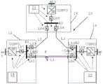
图1示意性地示出了呈互连三个换流站的直流电网形式的直流(DC)电力输送系统,Figure 1 schematically shows a direct current (DC) power transmission system in the form of a direct current grid interconnecting three converter stations,
图2示意性地示出了包括第一、第二和第三故障处理单元以及主控制单元的故障处理装置,Figure 2 schematically shows a fault handling device comprising first, second and third fault handling units and a main control unit,
图3示出了在主控制单元中执行的多个方法步骤的流程图,Figure 3 shows a flow chart of a number of method steps carried out in the main control unit,
图4示出了在第一故障处理单元中执行的多个方法步骤的流程图,Figure 4 shows a flow chart of a plurality of method steps performed in the first fault handling unit,
图5示出了在第二故障处理单元中执行的多个方法步骤的流程图,Figure 5 shows a flow chart of a plurality of method steps performed in the second fault handling unit,
图6示意性地示出了当处理第一电力线中发生的故障并且故障持续存在时直流电力系统中的多个电流和电压,Figure 6 schematically shows a number of currents and voltages in a DC power system when dealing with a fault occurring in the first power line and the fault persists,
图7示意性地示出了当正在处理在第一电力线中发生的故障并且故障被清除时直流电力系统中的多个电流和电压,Figure 7 schematically shows a number of currents and voltages in the DC power system when a fault occurring in the first power line is being processed and the fault is cleared,
图8示出了可以在直流电网中使用的双母线双断路器构造,和Figure 8 shows a dual busbar dual circuit breaker configuration that can be used in a DC grid, and
图9示意性地示出了包括用于实现故障处理装置的功能的至少一部分的计算机程序代码的计算机程序。Figure 9 schematically shows a computer program comprising computer program code for implementing at least a part of the functionality of the fault handling means.
具体实施方式Detailed ways
在下文中,将给出本发明的优选实施例的详细描述。Hereinafter, a detailed description of preferred embodiments of the present invention will be given.
图1示出了简化的多端直流(DC)电力系统10,例如高压直流(HVDC)电力系统,其包括连接到不同直流电力线的对应换流站中的至少两台变换器,其中每个换流站均连接到多条直流电力线,所述多条直流电力线中的至少一条是直流电力系统中的电力线,并且通过线路分离装置进行每个连接。在以下示例中,所有直流电力线都是直流电力系统中的电力线。但是,如稍后将看到的那样,情况并不一定总是如此。Figure 1 shows a simplified multi-terminal direct current (DC)
示例性电力系统10包括第一换流站12、第二换流站14和第三换流站16。第一换流站12经由第一电力线L1与第二换流站14互连。在此,第一换流站12包括第一线路分离装置LS1,第二换流站14包括第二线路分离装置LS2,以用于与第一电力线L1互连。第一换流站12还经由第二电力线L2与第三换流站16互连。在此,第一换流站12包括第三线路分离装置LS3,第三换流站16包括第四线路分离装置LS4,以用于与第二电力线L2互连。第二换流站14又经由第三电力线L3与第三换流站16互连。在这种情况下,第二换流站14包括第五线路分离装置LS5,第三换流站16包括第六线路分离装置LS6,以用于与第三电力线L3互连。The
第一换流站12包括第一变换器CONV1,该第一变换器CONV1可以是电压源变换器或电流源变换器。更具体地,该第一变换器CONV1可以是直流容错变换器,即,具有限制故障电流的能力的变换器。在电压源变换器的情况下,容错变换器可以是具有一个或多个拥有断路能力的直流断路器的全桥(FB)模块化多电平变换器(MMC)或半桥(HB)模块化多电平变换器(MMC),而在电流源变换器的情况下,其是具有直流容错能力的线性整流变换器(LCC)。变换器CONV1具有连接到第一交流系统AC1的交流(AC)侧和经由第七线路分离装置LS7连接到第一内部直流母线B1的直流侧,该内部直流母线B1也连接到第一线路分离装置LS1和第三线路分离装置LS3。The
以类似方式,第二换流站14包括第二变换器CONV2,该第二变换器CONV2也可以是上述类型中的任何一种的容错变换器,并且其交流侧连接到第二交流系统AC2,而其直流侧经由第八线路分离装置LS8连接到第二内部直流母线B2,该内部直流母线B2也连接至第二线路分离装置LS2和第五线路分离装置LS5。In a similar manner, the
以类似方式,第三换流站16包括第三台变换器CONV3,该第三台变换器CONV3可以是也可以不是上述任何类型的直流容错变换器。变换器CONV3具有连接到第三交流系统AC3的交流侧和经由第九线路分离装置LS9连接到第三内部直流母线B3的直流侧,该内部直流母线B3也连接到第四线路分离装置LS4和第六线路分离装置LS6。In a similar manner, the
由此可以看出,第一电力线L1将第一换流站12中的第一变换器CONV1与第二换流站14中的第二变换器CONV2互连,其中第一电力线L1经由第一线路分离装置LS1连接到第一变换器CONV1并且经由第二线路分离装置LS2连接到第二变换器CONV2。From this it can be seen that the first power line L1 interconnects the first converter CONV1 in the
在每个换流站中,还设有故障处理单元,该故障处理单元用于在故障期间控制变换器和线路分离装置。该控制装置用虚线箭头指示。因此,在第一换流站12中,存在第一故障处理单元18,该第一故障处理单元18控制第一变换器CONV1以及第一、第三和第七线路分离装置LS1、LS3和LS7。在第二换流站14中,存在第二故障处理单元20,该第二故障处理单元20控制第二变换器CONV2以及第二、第五和第八线路分离装置LS2、LS5和LS8。在第三换流站16中,存在第三故障处理单元22,其控制第三台变换器CONV3以及第四、第六和第九线路分离装置LS4、LS6和LS9。In each converter station, a fault handling unit is also provided, which is used to control the converter and the line separation device during the fault. The controls are indicated by dashed arrows. Thus, in the
如本领域中已知的那样,MMC可以由子模块组成,该子模块可以是半桥子模块、全桥子模块或混合子模块,例如钳位双电池类型的子模块。As known in the art, the MMC may be composed of sub-modules, which may be half-bridge sub-modules, full-bridge sub-modules or hybrid sub-modules, such as clamped dual-cell type sub-modules.
线路分离装置可以是混合断路器,例如混合HVDC断路器(HHBs)。作为替代方案,该线路分离装置可以是隔离开关,例如超快速隔离开关或高速开关(HSS)。隔离开关和HSS是一种机械开关,该机械开关在传导路径中获得机械分离,以实现变换器与电力线的分离,而混合断路器是一种既包括机械开关又包括电子开关以及非线性电阻器(如电涌放电器和负载换向开关)的装置,以中断流经断路器的电流。混合断路器也可以分成多个部分,其中每个部分均包括三个并联分支:第一分支,该第一分支带有隔离开关和负载换向开关;第二分支,该第二分支带有多个电子开关;第三分支,该第三分支为第三电涌放电器分支。隔离开关和断路器的操作最终将换流站与电力线隔离或分离。但是,断路器能够在高电压和电流水平下获得这种分离,而隔离开关通常需要零或较小的电流水平,以获得分离。The line separation devices may be hybrid circuit breakers, such as hybrid HVDC circuit breakers (HHBs). Alternatively, the line separation device may be an isolating switch, such as an ultra-fast isolating switch or a high speed switch (HSS). Disconnector and HSS is a mechanical switch that obtains a mechanical separation in the conduction path to achieve separation of the converter from the power line, while a hybrid circuit breaker is a mechanical switch that includes both mechanical and electronic switches as well as non-linear resistors Devices (such as surge arresters and load-reversing switches) to interrupt the flow of current through circuit breakers. Hybrid circuit breakers can also be divided into sections, where each section includes three parallel branches: a first branch with isolating switches and load-reversing switches; a second branch with multiple an electronic switch; a third branch, the third branch is a third surge arrester branch. The operation of the disconnectors and circuit breakers ultimately isolates or separates the converter station from the power line. However, circuit breakers are able to achieve this separation at high voltage and current levels, whereas disconnectors typically require zero or less current levels to achieve separation.
当变换器是直流容错变换器(例如,基于子模块的容错LCC或MMC)时,该线路分离装置有利地是隔离开关或高速开关,而在变换器采用半桥或其它类型的子模块的情况下该线路分离装置通常是混合断路器,该半桥或其它类型的子模块仅能够在一个方向上限制故障电流,其中在封锁子模块(即,子模块中的开关被关断)时实现这种故障电流限制。When the converter is a DC fault tolerant converter (eg, a submodule based fault tolerant LCC or MMC), the line separation device is advantageously an isolation switch or a high speed switch, whereas in the case of the converter employing a half bridge or other type of submodule The line separation device is usually a hybrid circuit breaker, the half-bridge or other type of sub-module is only capable of limiting the fault current in one direction, where this is achieved when the sub-module is blocked (ie, the switches in the sub-module are turned off). A fault current limit.
除了电力线之外,第一电力线L1通常是架空线,而第二和第三电力线L2和L3可以是架空线或电缆。In addition to the power line, the first power line L1 is typically an overhead line, while the second and third power lines L2 and L3 may be overhead lines or cables.
在此还应该提及的是,能够从电力系统以及本地直流母线B1、B2和B3中省去第七,第八和第九线路分离装置LS7、LS8和LS9。It should also be mentioned here that the seventh, eighth and ninth line separation means LS7, LS8 and LS9 can be omitted from the power system as well as from the local DC busbars B1, B2 and B3.
故障处理单元是故障处理装置的一部分。在图2中示出这种故障处理装置26的一个示例并且故障处理装置26包括第一、第二和第三故障处理单元18、20和22以及主控制单元24。这里,第一、第二和第三故障处理单元18、20和22也显示为彼此以及与主控制单元24通信。此处使用双向虚线箭头显示通信。The fault handling unit is part of the fault handling means. An example of such a
HVDC电网的概念已经发展并且很大程度上受基于VSC的HVDC输送系统的发展驱动。The concept of HVDC grids has evolved and is largely driven by the development of VSC-based HVDC transmission systems.
由于具有高惯性的发电机组中存储的动能很大,交流电网在失去其稳定性之前可以承受几百毫秒的故障持续时间。在直流电网中,该系统的惯性非常低并且取决于该系统的电容和电感。为避免直流系统电力中断,必须尽快清除故障,尤其是对于经常发生瞬态干扰的架空线(OHL)而言。因此,HVDC电网的实现取决于在限制直流故障电流、隔离故障部分并实现系统10的正常部件的重启过程中与直流断路器或直流故障电流限制或直流容错变换器拓扑有关的技术的发展。Due to the large kinetic energy stored in gensets with high inertia, the AC grid can withstand fault durations of several hundred milliseconds before losing its stability. In a DC grid, the inertia of the system is very low and depends on the capacitance and inductance of the system. To avoid power interruptions in DC systems, faults must be cleared as quickly as possible, especially for overhead lines (OHL) where transient disturbances often occur. Therefore, the implementation of HVDC grids depends on the development of techniques related to DC circuit breaker or DC fault current limiting or DC fault tolerant converter topologies in limiting DC fault currents, isolating faulted parts and enabling restarting of normal components of the
在具有架空线的输送系统中,线路故障比在电缆输送中更为频繁发生。此外,架空线也遭受临时故障,即,故障在电弧熄灭之后消失,从而允许线路重启。在此类故障期间,希望一旦故障已经消除后就重新给断开的线路供电并恢复电力输送。在带有LCC变换器的点对点HVDC系统中,可以将这种做法用作重启过程。In transmission systems with overhead lines, line failures occur more frequently than in cable transmission. In addition, overhead lines also suffer from temporary faults, ie, the fault disappears after the arc is extinguished, allowing the line to restart. During such a fault, it is desirable to re-energize the disconnected line and restore power delivery once the fault has been eliminated. In point-to-point HVDC systems with LCC converters, this practice can be used as a restart procedure.
例如在巴黎举行的国际大电网会议2014中的R.Derakhshanfar,T.U.J onsson,Ueli Steiger,M.Habert撰写的“Hybrid HVDC breaker-A solution for future HVDCsystem”中已经观察了针对基于半桥MMC+HHB的HVDC电网的重启过程。For example, in "Hybrid HVDC breaker-A solution for future HVDCsystem" written by R.Derakhshanfar, T.U.J onsson, Ueli Steiger, M.Habert at the International Conference on Large Power Grids 2014 in Paris, it has been observed for half-bridge based MMC+HHB The restart process of the HVDC grid.
在新西兰举行的SPEC2016中的Vinothkumar K,Inger Segerqvist,NiclasJohannesson和Arman Hassanpoor撰写的“Sequential Auto-Reclosing Method forHybrid HVDC Breaker in VSC HVDC Links”中也对此进行了研究。This was also investigated in "Sequential Auto-Reclosing Method for Hybrid HVDC Breaker in VSC HVDC Links" by Vinothkumar K, Inger Segerqvist, Niclas Johannesson and Arman Hassanpoor at SPEC2016 in New Zealand.
尽管在文献中没有找到具有一个或多个直流容错变换器(例如FB MMC和LCC)的HVDC电网的重启程序,但以下是一种可行的程序。Although a restart procedure for HVDC grids with one or more DC fault tolerant converters (eg FB MMC and LCC) is not found in the literature, the following is a possible procedure.
为了便于理解,我们在此处讨论带有FB MMC的HVDC电网。For ease of understanding, here we discuss HVDC grid with FB MMC.
考虑图1所示的三端系统,其中变换器是全桥(FB)MMC变换器,而线路分离装置是高速开关(HSS),该高速开关只能在零电流或小电流水平下打开。与传统方法相对应的重启操作对于该系统构造而言可涉及在第一电力线L1中出现直流故障处所实施的以下程序:Consider the three-terminal system shown in Figure 1, where the converter is a full-bridge (FB) MMC converter, and the line separation device is a high-speed switch (HSS) that can only be turned on at zero or small current levels. A restart operation corresponding to the conventional method may involve, for this system configuration, the following procedure carried out at the occurrence of a DC fault in the first power line L1:
a)在第一和第二换流站12和14处的线路保护算法检测故障并封锁或部分封锁变换器CONV1和CONV2。借助通信或任何保护机制也可以封锁或部分封锁变换器CONV3。a) Line protection algorithms at the first and
b)这导致HVDC电网10中的电压为零,并且故障电流减小为零,将HSS LS1和LS2断开以隔离故障线路。b) This causes the voltage in the
c)现在,HVDC电网的其余部分可以将直流电压增加到故障前的值并等待消电离完成。为了使直流电网系统电压增加恢复到故障前的电压,所需时间将接近消电离时间。因此,在重启尝试期间,HVDC电网中的整个有功功率传输保持为零。c) The rest of the HVDC grid can now increase the DC voltage to the pre-fault value and wait for the deionization to complete. In order for the DC grid system voltage increase to return to the pre-fault voltage, the time required will be close to the deionization time. Therefore, during the restart attempt, the entire active power transfer in the HVDC grid remains zero.
d)在第一次消电离时间结束时,故障线路上的变换器CONV1和CONV2的线路HSS(即,LS1和LS2)被闭合(与直流预插入电阻器(PIR)一起,以限制相应交流侧中的扰动)。d) At the end of the first deionization time, the lines HSS (ie, LS1 and LS2) of the converters CONV1 and CONV2 on the faulty line are closed (together with the DC pre-insertion resistor (PIR) to limit the corresponding AC side perturbation in ).
e)如果故障仍然存在,则HVDC电网中的所有变换器都将馈入故障。因此,HVDC电网中的所有变换器再次被封锁以将故障电流减小到零,并且HSS LS1和LS2被断开以隔离故障第一电力线L1。e) If the fault still exists, all converters in the HVDC grid will feed the fault. Therefore, all converters in the HVDC grid are blocked again to reduce the fault current to zero, and the HSS LS1 and LS2 are opened to isolate the faulty first power line L1.
f)重复上述从a)开始的步骤,直到达到一定数量的重启尝试为止。在涉及失败的重启尝试的永久性直流故障情景中会观察到这种情况。在这种情况下,通过断开HSS LS1和LS2可以永久隔离故障线路,而系统的其余部分将恢复正常运行。f) Repeat the above steps from a) until a certain number of restart attempts are reached. This is observed in permanent DC failure scenarios involving failed restart attempts. In this case, by disconnecting HSS LS1 and LS2 the faulty line can be permanently isolated and the rest of the system will resume normal operation.
g)如果故障已经消除或是暂时的,则变换器应将其运行模式更改为故障前运行模式并开始输电。在涉及成功重启尝试的临时直流故障情景中可以观察到这种情况。g) If the fault has been eliminated or is temporary, the converter shall change its operating mode to the pre-fault operating mode and start transmission. This can be observed in temporary DC failure scenarios involving successful restart attempts.
可以观察到,对于重启的整个过程,直流电网中的总功率变为零,并且与交流系统之间没有功率交换或只有很少的功率交换。当在大约一秒钟的时间内没有可用功率时(对于3次重启尝试),这将对电力系统的瞬态稳定性产生不利影响。为了克服该缺点,需要一种智能方式来处理具有一个或多个变换器的HVDC电网的重启操作,这具有直流容错变换器的优势。It can be observed that for the whole process of restart, the total power in the DC grid becomes zero and there is no or only little power exchange with the AC system. This will adversely affect the transient stability of the power system when no power is available for about a second (for 3 restart attempts). To overcome this disadvantage, an intelligent way to handle restarting operations of HVDC grids with one or more converters is required, which has the advantages of DC fault tolerant converters.
因此,需要一种智能程序,用于在临时和永久性故障时重启HVDC电网,特别是使用直流容错变换器进行HVDC电网的重启操作。本发明的实施例有效地增强了电力系统的可用性和安全性,其中,HVDC电网采用一个或多个直流容错变换器。对于具有FB MMC、LCC以及HBMMC的多端HVDC电网,可以在需要在临时/永久故障时重启的所有情景下采用本发明的实施例。Therefore, there is a need for an intelligent procedure for restarting the HVDC grid in the event of temporary and permanent faults, especially using DC fault tolerant converters for restarting the HVDC grid. Embodiments of the present invention effectively enhance the availability and safety of power systems wherein the HVDC grid employs one or more DC fault tolerant converters. For a multi-terminal HVDC grid with FB MMC, LCC and HBMMC, embodiments of the present invention can be employed in all scenarios requiring restart on temporary/permanent failures.
现在将参照图3、4、5、6和7描述根据实施例执行的故障处理,其中图3示出了在主控制单元24中执行的多个方法步骤的流程图,图4示出了在第一故障处理单元18中执行的多个方法步骤的流程图,图5示出了在第二故障处理单元20中执行的多个方法步骤的流程图,图6示意性地示出了当处理在第一电力线中发生的故障并且故障仍然存在时直流电力系统中的多个电流和电压,图7示出了当故障被清除时针对在第一电力线上发生的故障的直流电力系统中的多个电流和电压。Fault handling according to an embodiment will now be described with reference to Figures 3, 4, 5, 6 and 7, wherein Figure 3 shows a flow chart of a number of method steps carried out in the
在假设变换器均为直流容错变换器的前提下执行所有正在执行的步骤。All the steps being performed are performed under the assumption that the converters are all DC fault tolerant converters.
最初,变换器以某些稳态水平在直流母线B1、B2和B3上输出直流电压Udp_B1、Udp_B2、Udp_B3。然后,在步骤28中,例如在第一电力线L1上可能检测到在直流电力系统10中的电力线上发生的故障F,可以由第一故障处理单元18和/或由第二故障处理单元20实施检测。然后可能在时间Tf检测到故障。随后,故障处理单元18和20之一或两者可以将故障报告给主控制单元24。该故障处理单元18和20还可以封锁或部分封锁其对应的变换器。因此,第一故障处理单元18可以在步骤34中至少部分地封锁第一变换器CONV1,第二故障处理单元20可以在步骤52中至少部分地封锁第二变换器CONV2。而且第三故障处理单元22可以至少部分地封锁第三台变换器CONV3,该第三故障处理单元22可以从第一故障处理单元18、第二故障处理单元20或主控制单元24获知该故障。这种封锁或部分封锁导致直流电流减少并且最终变为零。由此可见,可以在针对直流电力系统10的所有变换器执行的封锁操作中进行第一变换器CONV1的封锁或部分封锁。Initially, the converter outputs DC voltages Udp_B1 , Udp_B2 , Udp_B3 on DC buses B1 , B2 and B3 at certain steady state levels. Then, in
在流过故障的第一电力线L1的电流变为零之后,第一故障处理单元18操作第一线路分离装置LS1并且第二故障处理单元20操作第二线路分离装置LS2以将故障的第一电力线L1与直流系统10隔离开。这样做之后,成功的隔离将传达给主控制单元24。After the current flowing through the faulty first power line L1 becomes zero, the first
在给定的示例中,也可能发生第一故障处理单元18被告知要隔离第一换流站12,而第二故障处理单元20被告知第二换流站14仅与故障线路L1断开连接。In the given example, it may also happen that the first
因此,主控制单元24接收关于检测到的故障和故障线路L1的信息,然后在步骤30中确定要隔离的换流站。Thus, the
可以选择最匹配隔离标准的换流站,来确定要隔离哪个换流站。因此可以基于该电力线的一端处的换流站比电力线的另一端处的换流站更好地满足隔离标准来确定应该隔离电力线一端处的换流站。在这方面,主控制单元24可以具有关于每个换流站和直流系统10之间存在的连接数量的知识。也可以基于电力系统10的安全分析来建立待隔离的换流站。还可以考虑每个换流站传输的电量,其中可以选择传输最低电量的变换器。另外能够对不同条件进行加权或优先排序,其中连接的数量可以比电量具有更高的权重,反之亦然。另一种可能性是选择了其故障处理单元首先报告故障的换流站。最后也可以通过随机选择来实现。The converter station that best matches the isolation criteria can be selected to determine which converter station to isolate. It can therefore be determined that a converter station at one end of the power line should be isolated based on the fact that the converter station at one end of the power line meets the isolation criteria better than the converter station at the other end of the power line. In this regard, the
在给定的示例中,选择第一换流站12用于隔离。因此,在步骤32中主控制单元24将该决定通知第一故障处理单元18和第二故障处理单元20。主控制单元24也可以通知第三故障处理单元22。主控制单元24还可以向HVDC电网中连接的所有换流站发送反映此选择的新的功率指令。In the given example, the
作为替代方案,可以存在与第一、第二和第三故障处理单元18、20、22中的每个相关联的主控制单元。因此,可以为第一、第二和第三故障处理单元18、20、22中的每个装配专用的主控制单元,该主控制单元确定是否要隔离位于电力线一端处有故障的自有换流站。Alternatively, there may be a main control unit associated with each of the first, second and third
如前所述,在变换器CONV1、CONV2和CONV3被封锁并且通过直流线L1、L2、L3的直流电流以及各个换流站12、14、16的直流电流下降为零后,第一故障处理单元18与第二换流站CONV2中的第二线路分离装置LS2的操作协作配合地操作第一线路分离装置LS1,以在步骤35中将第一电力线L1与电力系统断开,这通常通过第一故障处理单元18断开第一线路分离装置LS1并且第二故障处理单元20断开第二线路分离装置LS2以将故障电力线L1与直流系统10隔离开来完成。As before, after the converters CONV1, CONV2 and CONV3 are blocked and the DC currents through the DC lines L1, L2, L3 and the DC currents of the
此后,在步骤36中,第一故障处理单元18将第一换流站12与直流系统10隔离开。这通过操作第一换流站12的至少一个另外的线路分离装置来完成。这意味着除了先前运行的第一线路分离装置LS1之外,第一故障处理单元18还操作第一换流站12的至少一个另外的线路分离装置,以实施隔离。可以做到这一点并且在图6和图7中举例说明的方式通过断开连接在内部母线B1和直流系统10的各个电力线之间的所有线路分离装置来实施。在本示例中,这涉及除了先前断开的第一线路分离装置LS1之外还断开第三线路分离装置LS3。另一种并且在某些情况下是优选的方式是替代地断开第七线路分离装置LS7。当通过封锁变换器CONV1,CONV2和CONV3将经过电力线L1的直流电流Idp_1下降为零时实施在FB MMC的情况中的隔离并且从而可以断开HSS形式的线路分离装置LS3或LS7。在时间点To1实施断开。如果是带HHB的HB MMC,则变换器不会将故障电流降低为零,在这种情况下,仍可能会运行HHB形式的线路分离装置以断开并且中断通过其中的电流。Thereafter, in
在已经实施第一换流站10的隔离之后,可以通知主控制单元24,并且主控制单元24可以依次通知第二和第三故障处理单元20和22。可替代地,第一故障处理单元18可以自己通知第二和第三故障处理单元20和22。第一故障处理单元18也可以使得隔离与将第一电力线从直流系统10断开连接协调配合。第一、第二和第三线路分离装置LS1、LS2和LS3因此可以全部在时间点t01断开,该时间点也是第一断开时间点。After the isolation of the
然而,该系统10中的其它线路分离装置保持接通。因此,至少第四、第五和第六线路分离装置LS4、LS5和LS6保持接通。这意味着如果第七线路分离装置LS7用于隔离第一换流站,则第三线路分离装置LS3也可以保持接通或不保持接通。However, the other line split devices in the
此时,第二换流站14和第三换流站16可被解锁并恢复运行且开始交换直流电网10中的电网功率P。第一变换器CONV1也可在步骤37中被第一故障处理单元18解锁。因此,可以在对直流电力系统10的所有换流站进行解锁时对第一换流站CONV1进行解锁。但是,在步骤38中也可以继续将第一变换器CONV1连接到交流系统AC1,并且如果需要则向其提供无功功率,例如通过作为无功功率补偿装置(如STATCOM)运行而提供无功功率。在步骤40中,也可以操作或控制第一变换器CONV1以输出零直流电压。At this point, the
在第一电力线L1已经与第二换流站14断开连接或分离之后,并且在已经完成上述隔离而直流系统10的其余部分正常运行(即,第二换流站14和任何其它换流站16之间的电力线L3处于运行状态中)之后,在步骤42中通过第一故障处理单元测试线路状态,以检查是否已经清除故障F。After the first power line L1 has been disconnected or detached from the
可以通过在第一重接通时间点Tr1接通第一线路分离装置LS1来进行测试,其中Tr1-To1是消电离时间。可以组合该接通并且有时在直流电压Udp_B1从零增加之前进行接通。The test can be carried out by switching on the first line separation device LS1 at the first re-switching time point Tr1, where Tr1-To1 is the deionization time. The switch-on can be combined and sometimes performed before the DC voltage Udp_B1 increases from zero.
如果故障仍然存在,则这将导致故障电力线L1中的故障电流Idp_1增加。但是,如果故障已清除,则不会流过此类电流。If the fault still exists, this will cause the fault current Idp_1 in the faulty power line L1 to increase. However, if the fault is cleared, no such current will flow.
因此,在步骤42中第一故障处理单元18通过增加直流电压检查是否已经清除故障,该直流电压可以增加到故障前直流电压值,并且如果在步骤44中已经清除了故障,则可以通知第二故障处理单元20,随后在步骤48中恢复出故障的直流线路L1的连接或对其重新连接并将第一变换器CONV1重新连接到直流系统10以及恢复故障前的操作条件。这可以涉及与由第二故障处理单元20操作第二线路分离装置LS2协作配合地由第一故障处理单元18操作第一线路分离装置LS1,以重新连接第一电力线L1和用于隔离的其它线路分离装置,以将第一换流站12重新连接到直流电力系统10。这意味着在图7的示例中,可以通过接通第三线路分离装置LS3和被通知的第三故障处理单元22来恢复至第三换流站CONV3的连接。此后,参见图7可以通过所有变换器恢复直流系统10的故障前运行条件,这涉及该换流器使用故障前电压Udp1、Udp2、Udp3。Therefore, the first
但是,如果在步骤44判断为故障未清除,则继续并检查是否已达到测试超时。However, if it is determined at
通常,只能执行有限数量的线路状态测试,例如三个,如果达到了最大允许测试数量,则达到测试超时。Typically, only a limited number of line status tests, such as three, can be performed, and if the maximum allowed number of tests is reached, the test timeout is reached.
在步骤46中判断为没有达到测试超时的情况下,在步骤50中第一故障处理单元18封锁或部分封锁第一变换器CONV1,以将用于测试的电流减小到零,在第二断开时间点To2断开第一线路分离装置LS1并且在步骤51中对第一变换器进行解锁。In the case where it is determined in
然后,在步骤38中第一变换器CONV1继续并且在需要时提供无功功率而且在步骤40中再次将直流电压降低为零。Then, the first converter CONV1 continues in
然后,第一故障处理单元18随后在步骤42中再次检查是否已经清除故障,这可以通过在第二重新接通时间点Tr2接通第一线路分离装置LS1来完成,其中Tr2-To2是第二消电离时间。在这种情况下,接通也可以与直流电压从零开始增加相结合或在增加之前进行。The first
如果在步骤44中判断为故障已清除,则在步骤48中恢复L1的连接,并且在故障前的操作条件下重新连接第一变换器,如果在步骤44中判断为故障未清除则在步骤46中检查测试超时,其中如果尚未达到测试超时,则在步骤50和51中封锁、断开第一线路分离装置LS1并且进行解锁,在步骤42中在第三消电离时间To3-Tr3进行另一个测试。If it is determined in
然而,如果在步骤46中判断为达到测试超时,则在步骤49中第一故障处理单元18将第一直流线路L1与直流系统10永久断开,并且使第一变换器CONV1恢复操作。通过封锁第一变换器CONV1并随后断开且保持第一线路分离装置LS1永久断开来获得永久断开连接。使第一变换器恢复运行的操作可以依次包括:对第一变换器进行解锁、将直流电压增加到故障前直流电压电平和接通线路分离装置LS3。However, if it is determined in
第二故障处理单元20同时执行的操作如下:The operations performed by the second
在第二换流站14中,在步骤52中封锁第二变换器CONV2以及确保通过第一电力线L1的直流电流降低到零之后,在步骤54中第二故障处理单元20与第一故障处理单元18协同配合将第一电力线L1与直流系统10断开连接。这通过第二故障处理单元20断开第二线路分离装置LS2和第一故障处理单元18断开第一线路分离装置LS1来完成。因此,断开连接涉及操作第二线路分离装置LS2以及第一故障处理单元18操作第一线路分离装置LS1以将第一电力线L1与直流系统分开,并且如上文所见这是在检查是否已清除故障F之前完成。In the
在此之后并且在第一换流站12已经与直流系统10隔离之后,在步骤56中第二故障处理单元20对第二变换器进行解锁,以允许第二换流站14恢复与直流系统的另一个非隔离的换流站一起运行。因此,可以开始在直流电网中交换功率Pin_grid。After this and after the
由此可以看出,第二变换器CONV2的封锁发生在第二换流站14与第一电力线L1分离之前,并且解锁发生在隔离步骤之后。From this it can be seen that the blocking of the second converter CONV2 takes place before the separation of the
然后,向第二故障处理单元20通知任何成功的重接通尝试或是否已达到测试超时,这可以由第一故障处理单元18或主控制单元24完成。如果在步骤58中判断为故障已清除,则在步骤62中第二故障处理单元20重新连接线路L1,这通过接通第二线路分离装置LS2来完成。然而,如果在步骤58中判断为没有清除故障,即,如果已经达到测试超时,则在步骤60中第二故障处理单元20保持第二换流站14与第一电力线L1永久断开。因此保持第二线路分离装置LS2永久断开。The second
对于FB MMC和高速开关(HSS)而言也可以按照以下方式描述操作。对于第一电力线L1中的直流故障以及在隔离第一换流站12过程中使用第七线路分离装置LS7时,重启操作涉及以下过程:The operation can also be described as follows for FB MMC and High Speed Switching (HSS). For a DC fault in the first power line L1 and when the seventh line separation device LS7 is used in isolating the
a)在第一和第二换流站12和14处的线路保护算法检测故障F并且封锁变换器CONV1和CONV2。借助通信或自身的保护算法也可以封锁变换器CONV3。a) Line protection algorithms at the first and
b)这导致HVDC电网10中的电压为零,并且故障电流在HVDC电网10中减小为零。b) This causes the voltage in the
c)现在,在该方案中,连接到故障线路L1、LS1和LS2的所有高速开关都断开。c) Now, in this scenario, all high speed switches connected to the faulty lines L1, LS1 and LS2 are open.
d)在电力线L1断开连接时,主控制单元24传达要隔离哪个变换器,在该示例中要隔离的变换器为CONV1。如果直流开关站配备了双母线方案或一个半断路器方案的方案,则将断开对应的线路分离装置以及LS7,在该双母线方案或一个半断路器方案中可以形成2个单独的母线(Bla和Blb)。图8示出了如何实现双母线的示例。d) When the power line L1 is disconnected, the
e)此后,主控制单元24传达直流电网的新的运行状况,并且HVDC电网的其余部分可以将直流电压增加到新的值并在第二和第三换流站14和16处继续与任意连接的交流电网进行功率交换。第一换流站12也可以继续用无功功率支持连接的交流系统AC1。可以通过使用零直流电压或在消电离期间提高直流环节电压作为STATCOM来支持交流系统。e) After this, the
I.优选的是在零直流电压条件下操作第一变换器CONV1并支持交流系统。在第一消电离时间Tr1结束时,断开的换流站12的故障的线路L1仅尝试通过接通LS1(连同DC PIR一起来限制相应交流侧的扰动)来尝试重启。如果变换器在零直流电压下运行,则直流电压应平稳增加。在直流电压从零开始增加的过程中,可以通过电流超过标称值的增加来轻松识别故障的存在。如果故障仍然存在,则将减小第一变换器CONV1的电压Udp_Bl,以使故障电流为零,使得可以再次断开HSS LS1。I. It is preferable to operate the first converter CONV1 under zero DC voltage conditions and support the AC system. At the end of the first deionization time Tr1, the failed line L1 of the disconnected
II.替代地,可以在消电离期间使直流电压Udp_B1增加,以缩短出现临时故障时建立功率流的时间。如果故障仍然存在,则封锁第一变换器CONV1,以将故障电流减小为零,使得可以断开HSS LS1。II. Alternatively, the DC voltage Udp_B1 can be increased during deionization to shorten the time to establish power flow in the event of a temporary fault. If the fault still exists, the first converter CONV1 is blocked to reduce the fault current to zero so that the HSS LS1 can be switched off.
e)在整个重启尝试过程中,第一变换器CONV1可以在不中断或中断最少的情况下为交流系统提供支持。同样,由于HSS LS2和LS3处于断开状态,因此HVDC电网中的实际功率流不会受到影响。e) The first converter CONV1 can provide support for the AC system with no or minimal interruptions throughout the restart attempt. Also, since the HSS LS2 and LS3 are disconnected, the actual power flow in the HVDC grid will not be affected.
f)重复上述c)的步骤,直到设置的重启尝试次数。在涉及失败的重启尝试的永久性直流故障情景下会观察到这种情况。在这种情况下,通过断开HSS LS1和LS2永久隔离故障线路。第一换流站连接回直流系统,而系统的其余部分应以新的功率命令继续正常运行。f) Repeat the steps in c) above until the set number of restart attempts. This is observed under permanent DC failure scenarios involving failed restart attempts. In this case, permanently isolate the faulty line by disconnecting HSS LS1 and LS2. The first converter station is connected back to the DC system, while the rest of the system should continue to operate normally with the new power command.
g)如果故障已消除/清除,则可以将第一变换器CONV1的参考电压设置为故障前的直流电压,并且可以使用预插入电阻器,随后的预插入电阻器旁路接通HSS、LS2和LS7。之后,所有变换器将其运行模式更改为故障前运行模式。在涉及成功重启尝试的临时直流故障情景中可以观察到这种情况。g) If the fault has been removed/cleared, the reference voltage of the first converter CONV1 can be set to the DC voltage before the fault and a pre-insertion resistor can be used, the subsequent pre-insertion resistor bypasses HSS, LS2 and LS7. Afterwards, all converters change their operating mode to pre-failure operating mode. This can be observed in temporary DC failure scenarios involving successful restart attempts.
此处应注意,如果在接通线路连接开关后直流电压增加,则可以避免使用预插入电阻器。It should be noted here that the use of pre-inserted resistors can be avoided if the DC voltage increases after switching on the line connection switch.
在图6和7中观察到,在建议的重接通方案中,在尽可能短的时间内建立HVDC电网中的功率流,这导致增强的系统可用性和提高的瞬态稳定性。It is observed in Figures 6 and 7 that in the proposed reconnection scheme, the power flow in the HVDC grid is established in the shortest possible time, which results in enhanced system availability and improved transient stability.
在上面的示例中,如果直流电网具有LCC,CONV1为LCC。为了使变换器的直流电流为零,LCC可以延迟运行,而不是像FB MMC那样进行封锁/部分封锁。LCC无法使用无功功率支持交流电网。在消电离时间内将LCC与直流电网隔离后,以零直流电压运行LCC也可能不是最好的选择。In the example above, if the DC grid has an LCC, CONV1 is the LCC. In order to make the DC current of the converter zero, the LCC can run with a delay instead of blocking/partial blocking like the FB MMC. The LCC cannot support the AC grid with reactive power. Running the LCC at zero DC voltage may also not be the best option after isolating the LCC from the DC grid during the deionization time.
因此,除了增强所连接的交流系统的瞬态稳定性之外,所提出的程序还导致系统可用性和电力系统安全性得到改善。这也减少了重启期间整个HVDC电网中的扰动传播。由于将故障扰动降到了最低,因此降低了阀和其它设备上的电流应力。因此,阀和其它设备不会在每次重启尝试时受到电流应力。减少了直流电网中的断电,使得变换器的其余部分可以吸收直流电网中的功率。由于减少重启时电网中的扰动,因此在整个重启周期的故障情景下,在VSC情况下隔离的变换器可以继续使用无功功率支持连接的交流系统。Therefore, in addition to enhancing the transient stability of the connected AC system, the proposed procedure also leads to improved system availability and power system safety. This also reduces disturbance propagation throughout the HVDC grid during restart. Current stress on valves and other equipment is reduced by minimizing fault disturbances. Therefore, valves and other equipment are not subject to current stress on each restart attempt. Blackouts in the DC grid are reduced so that the rest of the converter can absorb power in the DC grid. Due to the reduced disturbances in the grid upon restart, the converter isolated in the VSC case can continue to support the connected AC system with reactive power under fault scenarios throughout the restart cycle.
因此,可以对具有一个或多个直流容错变换器(例如线性整流变换器(LCC)、FBMMC和混合变换器)的HVDC电网执行上述方案。但是,不限于这些变换器。如果使用其它类型的变换器,则可以省略变换器的封锁和/或将直流电压降至零。在这种情况下,在测试过程中电路断路器的接通可以是逐渐接通,其中,一个或多个部分正在闭合。这种操作模式的优点是限制了线路分离装置的开关上的应力。Therefore, the above scheme can be implemented for HVDC grids with one or more DC fault tolerant converters such as linear rectifier converters (LCCs), FBMMCs and hybrid converters. However, it is not limited to these converters. If other types of converters are used, the blocking of the converters can be omitted and/or the DC voltage can be reduced to zero. In this case, the closing of the circuit breaker during the test may be a gradual closing, wherein one or more parts are closing. The advantage of this mode of operation is that the stress on the switches of the line split device is limited.
上面描述的方案也可以在径向直流电网中使用,在此形成两个单独的电网并且重启的影响最小。此外,该方案还可以用于包含HB MMC+HHB、FB MMC+HSS/隔离开关和LCC的混合直流电网。The solution described above can also be used in radial DC grids, where two separate grids are formed and the impact of restarting is minimal. In addition, the scheme can also be used for hybrid DC grids including HB MMC+HHB, FB MMC+HSS/disconnector and LCC.
如上所述,可以在故障处理装置中提供故障处理单元,其中故障处理装置可以仅包括第一故障处理单元,第一故障处理单元和主控制单元,第一故障处理单元和第二故障处理单元与主控制单元,或第一、第二和第三故障处理单元以及主控制单元。可以以处理器的形式提供故障处理装置,该处理器具有相关的程序存储器,该程序存储器包括用于执行一个或多个故障处理单元的功能的计算机程序代码。故障处理装置还可以被实现为一个或多个部件,例如一个或多个现场可编程门阵列(FPGA)或专用集成电路(ASIC)。上文提到的计算机程序代码也可以被提供为计算机程序产品,其包括具有计算机程序代码的数据载体,该计算机程序代码用于实施一个或多个故障处理单元的功能。图9示出了具有该计算机程序代码66的CD-ROM盘形式的数据载体64。As described above, a fault processing unit may be provided in the fault processing apparatus, wherein the fault processing apparatus may only include the first fault processing unit, the first fault processing unit and the main control unit, and the first fault processing unit and the second fault processing unit are related to The main control unit, or the first, second and third fault handling units and the main control unit. The fault handling means may be provided in the form of a processor having associated program memory including computer program code for carrying out the functions of one or more fault handling units. The fault handling means may also be implemented as one or more components, such as one or more field programmable gate arrays (FPGAs) or application specific integrated circuits (ASICs). The computer program code mentioned above can also be provided as a computer program product comprising a data carrier with computer program code for implementing the functions of one or more fault handling units. FIG. 9 shows a
尽管已经结合当前被认为是最实用和优选的实施例描述了本发明,但是应当理解的是本发明不限于所公开的实施例,相反本发明旨在涵盖各种修改以及等效的设备和装置。因此,本发明仅由所附权利要求书限制。While this invention has been described in connection with what is presently considered to be the most practical and preferred embodiments, it is to be understood that this invention is not limited to the disclosed embodiments, but on the contrary, the invention is intended to cover various modifications and equivalent apparatus and arrangements . Accordingly, the present invention is to be limited only by the appended claims.
Claims (17)
Applications Claiming Priority (1)
| Application Number | Priority Date | Filing Date | Title |
|---|---|---|---|
| PCT/EP2017/079580WO2019096402A1 (en) | 2017-11-17 | 2017-11-17 | Fault handling in a dc power system |
Publications (2)
| Publication Number | Publication Date |
|---|---|
| CN111357162Atrue CN111357162A (en) | 2020-06-30 |
| CN111357162B CN111357162B (en) | 2021-07-13 |
Family
ID=60582558
Family Applications (1)
| Application Number | Title | Priority Date | Filing Date |
|---|---|---|---|
| CN201780096926.7AActiveCN111357162B (en) | 2017-11-17 | 2017-11-17 | Troubleshooting in DC Power Systems |
Country Status (3)
| Country | Link |
|---|---|
| EP (1) | EP3711128B1 (en) |
| CN (1) | CN111357162B (en) |
| WO (1) | WO2019096402A1 (en) |
Families Citing this family (8)
| Publication number | Priority date | Publication date | Assignee | Title |
|---|---|---|---|---|
| CN111566886B (en)* | 2017-12-21 | 2021-10-19 | Abb电网瑞士股份公司 | Method of operating a converter station, converter station and HVDC transmission system |
| CN110323774B (en)* | 2019-07-04 | 2020-11-13 | 许继电气股份有限公司 | A kind of DC line fault restart method, VSC control method and device |
| CN110768221A (en)* | 2019-10-22 | 2020-02-07 | 华中科技大学 | An adaptive reclosing method for overhead flexible and direct power grids |
| CN110676821B (en)* | 2019-10-30 | 2021-06-25 | 南方电网科学研究院有限责任公司 | DC power transmission system and its switch breaking method and device |
| CN115241964A (en)* | 2021-04-23 | 2022-10-25 | 中电普瑞电力工程有限公司 | A power supply system of an offshore platform and its fault protection method |
| CN114050558B (en)* | 2021-11-16 | 2024-10-11 | 许昌许继软件技术有限公司 | A special control and protection architecture for parallel three-terminal DC transmission system |
| DE102023108119B4 (en)* | 2023-03-30 | 2024-11-14 | Rainer Marquardt | fault-tolerant DC network |
| WO2025061503A1 (en)* | 2023-09-22 | 2025-03-27 | Eaton Intelligent Power Limited | Power arrangement and method for operating a power arrangement |
Citations (8)
| Publication number | Priority date | Publication date | Assignee | Title |
|---|---|---|---|---|
| US3543045A (en)* | 1965-01-09 | 1970-11-24 | Asea Ab | Method and apparatus for connecting and disconnecting converter station between transmission lines |
| US3970898A (en)* | 1973-11-23 | 1976-07-20 | Zellweger Uster Ag | Method of automatically isolating a faulty section of a power line belonging to an electrical energy supply network, and arrangement for carrying out this method |
| CN102484430A (en)* | 2009-09-11 | 2012-05-30 | Abb研究有限公司 | Fault current limitation in DC power transmission systems |
| GB2523535A (en)* | 2013-12-18 | 2015-09-02 | Pwm Drives Ltd | Breaker circuit configurations for multi-terminal DC systems |
| CN106300294A (en)* | 2016-08-31 | 2017-01-04 | 许继电气股份有限公司 | Direct current network line fault restoration methods |
| CN106532756A (en)* | 2016-11-07 | 2017-03-22 | 许继集团有限公司 | DC fault ride-through method for flexible DC power grid |
| CN106936120A (en)* | 2015-12-30 | 2017-07-07 | 国网智能电网研究院 | A kind of direct current network line fault protection method |
| CN104350657B (en)* | 2012-03-05 | 2017-08-15 | 通用电气技术有限公司 | Troubleshooting method |
- 2017
- 2017-11-17EPEP17809214.4Apatent/EP3711128B1/enactiveActive
- 2017-11-17WOPCT/EP2017/079580patent/WO2019096402A1/ennot_activeCeased
- 2017-11-17CNCN201780096926.7Apatent/CN111357162B/enactiveActive
Patent Citations (8)
| Publication number | Priority date | Publication date | Assignee | Title |
|---|---|---|---|---|
| US3543045A (en)* | 1965-01-09 | 1970-11-24 | Asea Ab | Method and apparatus for connecting and disconnecting converter station between transmission lines |
| US3970898A (en)* | 1973-11-23 | 1976-07-20 | Zellweger Uster Ag | Method of automatically isolating a faulty section of a power line belonging to an electrical energy supply network, and arrangement for carrying out this method |
| CN102484430A (en)* | 2009-09-11 | 2012-05-30 | Abb研究有限公司 | Fault current limitation in DC power transmission systems |
| CN104350657B (en)* | 2012-03-05 | 2017-08-15 | 通用电气技术有限公司 | Troubleshooting method |
| GB2523535A (en)* | 2013-12-18 | 2015-09-02 | Pwm Drives Ltd | Breaker circuit configurations for multi-terminal DC systems |
| CN106936120A (en)* | 2015-12-30 | 2017-07-07 | 国网智能电网研究院 | A kind of direct current network line fault protection method |
| CN106300294A (en)* | 2016-08-31 | 2017-01-04 | 许继电气股份有限公司 | Direct current network line fault restoration methods |
| CN106532756A (en)* | 2016-11-07 | 2017-03-22 | 许继集团有限公司 | DC fault ride-through method for flexible DC power grid |
Also Published As
| Publication number | Publication date |
|---|---|
| WO2019096402A1 (en) | 2019-05-23 |
| EP3711128A1 (en) | 2020-09-23 |
| EP3711128B1 (en) | 2022-01-05 |
| CN111357162B (en) | 2021-07-13 |
Similar Documents
| Publication | Publication Date | Title |
|---|---|---|
| CN111357162B (en) | Troubleshooting in DC Power Systems | |
| CN104488156B (en) | The method of failture evacuation | |
| CN107645154B (en) | A new type of combined DC circuit breaker and its application method | |
| JP2020520210A (en) | Failure switch structure and recovery method in flexible DC converter station | |
| CN101297469B (en) | A transmission system and a method for control thereof | |
| CN107743672B (en) | The change of current return path in bipolar power Transmission system | |
| CN105849994B (en) | Breaker circuit | |
| CN107112745B (en) | DC power network | |
| CN103066573A (en) | Modular multi-level multi-terminal flexible direct current system direct current fault handling method | |
| JPWO2016207976A1 (en) | Power converter | |
| CN101297448A (en) | converter station | |
| CN106159913B (en) | Multi-terminal flexible direct current system direct current fault protecting method | |
| CN109687405A (en) | A kind of combined hybrid dc circuit breaker of multiport and control method | |
| CN107615431B (en) | Bidirectional power valve, control method thereof and hybrid multi-terminal high-voltage direct-current system using bidirectional power valve | |
| CN112313852A (en) | HVDC transmission scheme | |
| JP2017011992A (en) | Power transmission system, power converter and switch | |
| CN111884196A (en) | A method and device for power supply recovery after a fault in a flexible DC distribution line | |
| US11770005B2 (en) | Fault handling | |
| EP2834897B1 (en) | Backup power system and grounding device for a backup power system | |
| CN111934290B (en) | A kind of multi-terminal DC circuit breaker and its control method | |
| US9893520B2 (en) | Switching device | |
| CN107732881A (en) | A kind of direct current network dc circuit breaker failure protection method and apparatus | |
| CN109361197A (en) | An overcurrent protection device and method | |
| Larruskain et al. | Requirements for fault protection in HVDC grids | |
| CN113872160B (en) | Distribution Network Distributed Power Coupling System |
Legal Events
| Date | Code | Title | Description |
|---|---|---|---|
| PB01 | Publication | ||
| PB01 | Publication | ||
| SE01 | Entry into force of request for substantive examination | ||
| SE01 | Entry into force of request for substantive examination | ||
| GR01 | Patent grant | ||
| GR01 | Patent grant | ||
| CP01 | Change in the name or title of a patent holder | Address after:Swiss Baden Patentee after:Hitachi energy Switzerland AG Address before:Swiss Baden Patentee before:ABB grid Switzerland AG | |
| CP01 | Change in the name or title of a patent holder | ||
| TR01 | Transfer of patent right | Effective date of registration:20240112 Address after:Zurich, SUI Patentee after:Hitachi Energy Co.,Ltd. Address before:Swiss Baden Patentee before:Hitachi energy Switzerland AG | |
| TR01 | Transfer of patent right |