Movatterモバイル変換


[0]ホーム

URL:


CN111356413A - Medical tool with tension band - Google Patents

Medical tool with tension band
Download PDF

Info

Publication number
CN111356413A
CN111356413ACN201880073653.9ACN201880073653ACN111356413ACN 111356413 ACN111356413 ACN 111356413ACN 201880073653 ACN201880073653 ACN 201880073653ACN 111356413 ACN111356413 ACN 111356413A
Authority
CN
China
Prior art keywords
link
belt
cross
tool member
band
Prior art date
Legal status (The legal status is an assumption and is not a legal conclusion. Google has not performed a legal analysis and makes no representation as to the accuracy of the status listed.)
Granted
Application number
CN201880073653.9A
Other languages
Chinese (zh)
Other versions
CN111356413B (en
Inventor
R·艾伯特
I·赫耶
Current Assignee (The listed assignees may be inaccurate. Google has not performed a legal analysis and makes no representation or warranty as to the accuracy of the list.)
Intuitive Surgical Operations Inc
Original Assignee
Intuitive Surgical Operations Inc
Priority date (The priority date is an assumption and is not a legal conclusion. Google has not performed a legal analysis and makes no representation as to the accuracy of the date listed.)
Filing date
Publication date
Application filed by Intuitive Surgical Operations IncfiledCriticalIntuitive Surgical Operations Inc
Priority to CN202410356386.3ApriorityCriticalpatent/CN118203426A/en
Publication of CN111356413ApublicationCriticalpatent/CN111356413A/en
Application grantedgrantedCritical
Publication of CN111356413BpublicationCriticalpatent/CN111356413B/en
Activelegal-statusCriticalCurrent
Anticipated expirationlegal-statusCritical

Links

Images

Classifications

Landscapes

Abstract

The medical device includes a first link, a second link, and a band. The proximal end portion of the first link is coupled to the shaft. The proximal portion of the second link is rotatably coupled to the distal portion of the first link about a first axis. The distal end portion of the second link includes a connector coupled to a tool member that is rotatable relative to the second link about a second axis that is non-parallel to the first axis. The first link defines a first guide channel and the second link defines a second guide channel. The distal end of the band is disposed within the first guide channel and the second guide channel and is coupled to the tool member. The second link is rotatable relative to the first link about a first axis as the distal end of the band is moved.

Description

Translated fromChinese
具有张力带的医疗工具Medical tool with tension band

相关申请的交叉引用CROSS-REFERENCE TO RELATED APPLICATIONS

本申请要求(于2017年12月14日提交)标题为“Medical Tools Having TensionBands(具有张力带的医疗工具)”的美国临时申请序列号62/598,620;(于2017年12月14日提交)标题为“Medical Tools Having Tension Bands(具有张力带的医疗工具)”的美国临时申请序列号62/598,626;以及(于2017年12月14日提交)标题为“Medical Tools HavingTension Bands(具有张力带的医疗工具)的美国临时申请序列号62/598,628的优先权,上述申请的全部内容通过引用并入本文。This application claims US Provisional Application Serial No. 62/598,620 (filed December 14, 2017) entitled "Medical Tools Having TensionBands"; (filed December 14, 2017) titled U.S. Provisional Application Serial No. 62/598,626 for "Medical Tools Having Tension Bands"; and (filed December 14, 2017) entitled "Medical Tools Having Tension Bands" Tools) of U.S. Provisional Application Serial No. 62/598,628, the entire contents of which are incorporated herein by reference.

技术领域technical field

本文所述的实施例涉及抓握工具,更具体地涉及医疗设备,并且还更具体地涉及内窥镜工具。更具体地,本文描述的实施例涉及包括可在例如外科应用中使用的张力带的设备。Embodiments described herein relate to grasping tools, more particularly medical devices, and still more particularly endoscopic tools. More specifically, the embodiments described herein relate to devices including tension bands that can be used, for example, in surgical applications.

背景技术Background technique

微创手术(MIS)的已知技术采用器械来操纵组织,其要么可以手动控制要么可以经由计算机辅助远程操作来控制。许多已知的MIS器械包括在轴的远端处安装在腕部机构上的治疗或诊断性末端执行器(例如,镊子、切割工具或烧灼工具)。在MIS程序中,末端执行器、腕部机构和轴的远端可以被插入患者的小切口或自然孔口中,以将末端执行器放置在患者体内的工作部位处。可选的腕部机构可用于改变末端执行器相对于轴的取向,以在工作部位执行期望的操作。已知的腕部机构通常为末端执行器的运动提供期望的自由度(DOF)。例如,对于镊子或其他抓握工具,已知的腕部机构通常能够相对于轴改变末端执行器的俯仰和偏航。腕部可以可选地为末端执行器提供侧倾(滚动,roll)DOF,或者可以通过滚动轴来实现侧倾DOF。末端执行器可以可选地具有附加机械DOF,例如抓握或刀片运动。在某些情况下,腕部和末端执行器机械DOF可以结合使用。例如,美国专利号5,792,135(于1997年5月16日提交)公开了一种机构,在该机构中腕部和末端执行器抓握DOF被结合在一起。Known techniques for minimally invasive surgery (MIS) employ instruments to manipulate tissue, which can be controlled either manually or via computer-assisted teleoperation. Many known MIS instruments include therapeutic or diagnostic end effectors (eg, forceps, cutting tools, or cautery tools) mounted on a wrist mechanism at the distal end of the shaft. In an MIS procedure, the end effector, wrist mechanism, and distal end of the shaft can be inserted into a small incision or natural orifice in the patient to place the end effector at the work site in the patient. An optional wrist mechanism can be used to change the orientation of the end effector relative to the shaft to perform the desired operation at the work site. Known wrist mechanisms generally provide the desired degrees of freedom (DOF) for movement of the end effector. For example, for tweezers or other grasping tools, known wrist mechanisms are often capable of changing the pitch and yaw of the end effector relative to the axis. The wrist can optionally provide a roll (roll) DOF for the end effector, or the roll DOF can be achieved through a roll axis. The end effector may optionally have additional mechanical DOF, such as gripping or blade motion. In some cases, a wrist and end effector mechanical DOF can be used in combination. For example, US Patent No. 5,792,135 (filed May 16, 1997) discloses a mechanism in which the wrist and end effector grasping DOF are combined.

为了使腕部机构和末端执行器能够进行期望的运动,已知的器械包括张力元件(例如,缆线),所述张力元件延伸穿过器械的轴并且将腕部机构连接到致动器(在本文中也称为后端机构)。致动器移动缆线以操作腕部机构。对于机器人或远程操作系统,后端机构是马达驱动的,并且能够被可操作地联接到处理系统,以为用户提供用户界面来控制器械。To enable the desired movement of the wrist mechanism and end effector, known instruments include tension elements (eg, cables) that extend through the shaft of the instrument and connect the wrist mechanism to the actuator ( Also referred to herein as the backend mechanism). The actuator moves the cable to operate the wrist mechanism. For robotic or teleoperated systems, the back end mechanism is motor driven and can be operably coupled to the processing system to provide a user interface for the user to control the instrument.

通过改进MIS方法和工具的有效性,患者将从中持续受益。例如,减小轴和腕部机构的尺寸和/或操作占地面积能够允许较小的进入切口,从而减少手术的负面影响,例如疼痛、结疤和不希望的愈合时间。但是,生产实现用于微创手术的临床期望功能的小直径医疗器械可能具有挑战性。具体地,仅通过“按比例缩小”部件来减小已知腕部机构的尺寸将不会导致有效的解决方案,因为所需的部件和材料特性不会按比例缩放。例如,腕部机构的有效实施可能很复杂,因为必须小心地将缆线穿过腕部机构,以在腕部机构的整个运动范围内保持缆线张力,并使一个旋转轴线与另一个的相互作用(或联接效应)最小化。此外,通常需要皮带轮和/或轮廓表面以减小缆线摩擦,这延长了器械寿命并允许操作而没有过多的力施加到腕部机构中的缆线或其他结构。由较小的结构(包括缆线和腕部机构的其他部件)引起的增大的局部力会导致缆线在存储和使用过程中出现不希望的加长(例如“拉伸”或“蠕变”)、缩短缆线寿命等。Patients will continue to benefit from improving the effectiveness of MIS methods and tools. For example, reducing the size and/or operating footprint of the shaft and wrist mechanism can allow for smaller access incisions, thereby reducing negative effects of the procedure, such as pain, scarring, and undesired healing time. However, producing small-diameter medical devices that achieve clinically desirable functions for minimally invasive procedures can be challenging. In particular, reducing the size of a known wrist mechanism by simply "scaling down" components will not lead to an efficient solution, since the required components and material properties will not be scaled. For example, effective implementation of a wrist mechanism can be complicated because cables must be carefully routed through the wrist mechanism to maintain cable tension throughout the wrist mechanism's entire range of motion and to reciprocate one axis of rotation to the other. effects (or coupling effects) are minimized. Additionally, pulleys and/or contoured surfaces are often required to reduce cable friction, which extends instrument life and allows operation without excessive force applied to cables or other structures in the wrist mechanism. Increased localized forces caused by smaller structures (including cables and other components of the wrist mechanism) can lead to unwanted lengthening (e.g. "stretching" or "creep") of the cables during storage and use ), shorten the cable life, etc.

此外,一些医疗器械具有末端执行器,该末端执行器需要电能才能实现临床功能,例如干燥、止血、切割、解剖、引流、切口、组织破坏、烧灼和血管密封。因此,已知的器械包括通过腕部机构到达末端执行器的待通电的部分的一个或多个导体。将腕部机构、驱动缆线和导线的所有部件安装成较小的直径(例如,小于约10mm),同时保持这些部件的必要强度和功能可能很困难。Additionally, some medical devices have end effectors that require electrical energy for clinical functions such as drying, hemostasis, cutting, dissection, drainage, incision, tissue destruction, cautery, and vessel sealing. Thus, known instruments include one or more conductors through the wrist mechanism to the portion of the end effector to be energized. It can be difficult to fit all components of the wrist mechanism, drive cables and leads to a small diameter (eg, less than about 10 mm) while maintaining the necessary strength and functionality of these components.

除了减小器械的尺寸之外,还期望开发可有效地一次性使用的低成本器械(即,仅以经济成本用于单次使用)。使用这种器械,每个MIS程序都可以使用新的灭菌器械执行,从而消除了繁琐且昂贵的器械重复使用灭菌程序。然而,许多当前的器械设计生产昂贵,因此为了经济起见,这些器械经过无菌再加工以用于多种外科手术程序。这些器械的部分成本可能是由于承受操作负荷的多股钨丝缆线和海波管部分。In addition to reducing the size of the device, it is also desirable to develop low-cost devices that can be effectively single-use (ie, only available for a single use at an economical cost). Using this instrument, every MIS procedure can be performed with a new sterilized instrument, eliminating the tedious and expensive instrument re-use sterilization procedure. However, many current instruments are designed to be expensive to produce, so for economy, these instruments are aseptically reprocessed for use in a variety of surgical procedures. Part of the cost of these instruments may be due to the stranded tungsten cable and hypotube sections that are subjected to operational loads.

因此,需要改进的内窥镜工具,包括具有减小的尺寸、减少的零件数、较低的材料成本的改进的腕部机构,以及包括具有增加的强度的张力构件。Accordingly, there is a need for an improved endoscopic tool, including an improved wrist mechanism with reduced size, reduced parts count, lower material cost, and including tension members with increased strength.

发明内容SUMMARY OF THE INVENTION

本发明内容介绍了本文描述的实施例的某些方面以提供基本的理解。本发明内容不是发明主题的广泛概述,并且也不旨在标识关键或重要元件或界定发明主题的范围。在一些实施例中,医疗设备包括第一连杆、第二连杆和带。第一连杆和第二连杆均具有近端部分和远端部分。第一连杆的近端部分联接到轴。第二连杆的近端部分可旋转地联接到第一连杆的远端部分。第二连杆可相对于第一连杆绕第一轴线旋转。第二连杆的远端部分包括连接器,该连接器联接到工具构件,该工具构件可相对于第二连杆绕第二轴线旋转。第二轴线不平行于第一轴线。第一引导通道被限定在第一连杆内,并且第二引导通道被限定在第二连杆内。带的远端部分布置在第一引导通道和第二引导通道内,并且联接到工具构件。当移动带的远端部分时,第二连杆可相对于第一连杆绕第一轴线旋转。This Summary presents certain aspects of the embodiments described herein in order to provide a basic understanding. This summary is not an extensive overview of the inventive subject matter, and is not intended to identify key or critical elements or to delineate the scope of the inventive subject matter. In some embodiments, the medical device includes a first link, a second link, and a strap. The first link and the second link each have a proximal end portion and a distal end portion. The proximal portion of the first link is coupled to the shaft. The proximal portion of the second link is rotatably coupled to the distal portion of the first link. The second link is rotatable relative to the first link about a first axis. The distal portion of the second link includes a connector coupled to a tool member that is rotatable relative to the second link about a second axis. The second axis is not parallel to the first axis. A first guide channel is defined within the first link, and a second guide channel is defined within the second link. A distal end portion of the strap is disposed within the first guide channel and the second guide channel and is coupled to the tool member. The second link is rotatable about the first axis relative to the first link when the distal portion of the belt is moved.

在一些实施例中,医疗设备包括第一连杆、第二连杆、工具构件和带。第一连杆联接到轴。第二连杆的近端部分联接到第一连杆,使得第二连杆可相对于第一连杆绕第一轴线旋转。引导通道由第二连杆限定。工具构件具有接触部分和皮带轮部分。接触部分被构造成接触目标组织。皮带轮部分可旋转地联接到第二连杆的远端部分,使得工具构件可相对于第二连杆绕第二轴线旋转。第二轴线不平行于第一轴线。带具有第一带部分和第二带部分。第一带部分设置在引导通道内,并且第二带部分联接到工具构件。带在第一带部分和第二带部分之间沿着带的纵向中心线扭转。当移动带时,工具构件可相对于第二连杆绕第二轴线旋转。In some embodiments, the medical device includes a first link, a second link, a tool member, and a strap. The first link is coupled to the shaft. A proximal portion of the second link is coupled to the first link such that the second link is rotatable relative to the first link about a first axis. The guide channel is defined by the second link. The tool member has a contact portion and a pulley portion. The contact portion is configured to contact the target tissue. The pulley portion is rotatably coupled to the distal end portion of the second link such that the tool member is rotatable relative to the second link about a second axis. The second axis is not parallel to the first axis. The belt has a first belt portion and a second belt portion. The first strap portion is disposed within the guide channel and the second strap portion is coupled to the tool member. The belt is twisted along the longitudinal centerline of the belt between the first belt portion and the second belt portion. The tool member is rotatable about the second axis relative to the second link when the belt is moved.

附图说明Description of drawings

图1是根据实施例的用于执行诸如外科手术的医疗程序的远程操作医疗系统的平面图。1 is a plan view of a teleoperated medical system for performing a medical procedure, such as surgery, according to an embodiment.

图2是图1所示的远程操作手术系统的用户控制台的透视图。FIG. 2 is a perspective view of a user console of the teleoperated surgical system shown in FIG. 1 .

图3是图1所示的远程操作手术系统的可选辅助单元的透视图。FIG. 3 is a perspective view of an optional auxiliary unit of the teleoperated surgical system shown in FIG. 1 .

图4是图1所示的远程操作手术系统的操纵器单元的正视图,该操纵器单元包括一组器械。4 is a front view of the manipulator unit of the teleoperated surgical system shown in FIG. 1, the manipulator unit including a set of instruments.

图5是根据实施例的处于第一构造的手术系统的器械的一部分的示意性透视图。5 is a schematic perspective view of a portion of an instrument of a surgical system in a first configuration, according to an embodiment.

图6和图7是图5所示的器械的该部分处于第一构造(图6)和第二构造(图7)的示意性俯视图。6 and 7 are schematic top views of the portion of the instrument shown in FIG. 5 in a first configuration (FIG. 6) and a second configuration (FIG. 7).

图8和图9是沿图6所示的线X1-X1截取的器械的该部分处于第一构造(图8)和第三构造(图9)的示意性前视截面图。8 and 9 are schematic front cross-sectional views of the portion of the instrument in a first configuration (FIG. 8) and a third configuration (FIG. 9) taken along line X1-X1 shown in FIG. 6. FIG.

图10是沿图6所示的线X2-X2截取的器械的该部分的示意性侧视截面图。FIG. 10 is a schematic side cross-sectional view of the portion of the instrument taken along the line X2 -X2 shown in FIG. 6 .

图11是根据实施例的处于第一构造的手术系统的器械的一部分的示意性透视图。11 is a schematic perspective view of a portion of an instrument of a surgical system in a first configuration, according to an embodiment.

图12-14是沿图11所示的线X1-X1截取的器械的该部分处于第一构造(图12)、第二构造(图13)和第三构造(图14)的示意性俯视截面图。12-14 are schematic illustrations of the portion of the instrument in a first configuration (FIG. 12), a second configuration (FIG. 13), and a third configuration (FIG.14 ) taken along the line X1- X1 shown in FIG. 11 Top section view.

图15-17是沿图12中所示的线X2-X2截取的器械的该部分处于第一构造(图15)、第二构造(图16)和第三构造(图17)的示意性侧视截面图。15-17 are schematic illustrations of the portion of the instrument in a first configuration (FIG. 15), a second configuration (FIG. 16), and a third configuration (FIG.17 ) taken along the line X2- X2 shown in FIG. 12 Sexual side view sectional view.

图18是根据实施例的手术系统的器械的一部分的示意性前视截面图。18 is a schematic front cross-sectional view of a portion of an instrument of a surgical system according to an embodiment.

图19-21是沿着线X19-X19(图19)、X20-X20(图20)和X21-X21(图21)截取的、包括在图18所示的器械内的带的示意性侧视截面图。19-21 are taken along lines X19-X19 (FIG.19 ), X20-X20 (FIG.20 ) andX21 -X21 (FIG. 21) included within the instrument shown in FIG. 18 Schematic side sectional view of the belt.

图22是根据实施例的手术系统的器械的一部分的示意图。22 is a schematic diagram of a portion of an instrument of a surgical system according to an embodiment.

图23-24是沿着线X23-X23(图23)和X24-X24(图24)截取的、包括在图22所示的器械内的带的示意性侧视截面图。23-24 are schematic side cross-sectional views of straps included within the instrument shown in FIG. 22, taken along lines X23-X23 (FIG.23 ) andX24 -X24 (FIG. 24).

图25是根据实施例的手术系统的器械的一部分的示意图。25 is a schematic diagram of a portion of an instrument of a surgical system according to an embodiment.

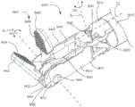
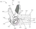
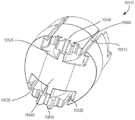
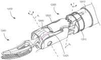
图26是根据实施例的处于第一构造的手术系统的器械的透视图。26 is a perspective view of an instrument of a surgical system in a first configuration, according to an embodiment.

图27是由图26所示的区域Z指示的器械的远端部分的放大透视图。FIG. 27 is an enlarged perspective view of the distal end portion of the instrument indicated by zone Z shown in FIG. 26 .

图28是图27所示的器械的远端部分的俯视图,以及图29是图27所示的器械的远端部分的分解透视图。28 is a top view of the distal end portion of the instrument shown in FIG. 27, and FIG. 29 is an exploded perspective view of the distal end portion of the instrument shown in FIG. 27. FIG.

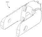
图30是图27所示器械的腕部组件的第一连杆的左侧透视图,以及图31是右侧透视图。30 is a left side perspective view of the first link of the wrist assembly of the instrument shown in FIG. 27, and FIG. 31 is a right side perspective view.

图32和图33是图27所示的器械的腕部组件的第二连杆的透视图。32 and 33 are perspective views of the second link of the wrist assembly of the instrument shown in FIG. 27 .

图34是图27所示的器械的末端执行器的第一工具构件的透视图。34 is a perspective view of a first tool member of the end effector of the instrument shown in FIG. 27 .

图35是图27所示的器械的末端执行器的第二工具构件的透视图。FIG. 35 is a perspective view of a second tool member of the end effector of the instrument shown in FIG. 27 .

图36是由图26所示的区域Z指示的器械的远端部分的放大透视图,其中器械处于第二构造。Figure 36 is an enlarged perspective view of the distal end portion of the instrument indicated by zone Z shown in Figure 26, with the instrument in a second configuration.

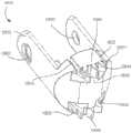
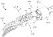
图37是根据实施例的手术系统的器械的远端部分的透视图。37 is a perspective view of a distal portion of an instrument of a surgical system according to an embodiment.

图38是图37所示的末端执行器和器械的带的透视图。38 is a perspective view of the strap of the end effector and instrument shown in FIG. 37 .

图39是图37所示的器械的带的一部分的透视图。FIG. 39 is a perspective view of a portion of the strap of the instrument shown in FIG. 37 .

图40是图37所示的器械的带的一部分和第一连杆的透视图。40 is a perspective view of a portion of the strap and first link of the instrument shown in FIG. 37 .

图41是图37所示的器械的腕部组件的第一连杆的左侧透视图。41 is a left side perspective view of the first link of the wrist assembly of the instrument shown in FIG. 37 .

图42是图37所示的器械的腕部组件的第二连杆的透视图。42 is a perspective view of the second link of the wrist assembly of the instrument shown in FIG. 37 .

图43和图44是图37所示的器械的末端执行器的第一工具构件和第二工具构件的透视图。43 and 44 are perspective views of the first tool member and the second tool member of the end effector of the instrument shown in FIG. 37 .

图45是图37所示的器械的带的一部分和第一工具构件的透视图。FIG. 45 is a perspective view of a portion of the strap and first tool member of the instrument shown in FIG. 37 .

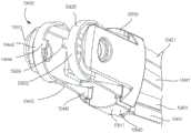
图46是根据实施例的手术系统的器械的远端部分的透视图。46 is a perspective view of a distal portion of an instrument of a surgical system according to an embodiment.

图47是图46所示的器械的远端部分的分解透视图。FIG. 47 is an exploded perspective view of the distal portion of the instrument shown in FIG. 46 .

图48是图46所示的器械的远端部分的透视图,其中轴和第二连杆被移除以显示末端执行器、带和第一连杆。Figure 48 is a perspective view of the distal portion of the instrument shown in Figure 46 with the shaft and second link removed to show the end effector, strap and first link.

图49是图46所示的器械的腕部组件的第一连杆的左侧透视图,以及图50是图46所示的器械的腕部组件的第一连杆的右侧透视图。49 is a left side perspective view of the first link of the wrist assembly of the instrument shown in FIG. 46 , and FIG. 50 is a right side perspective view of the first link of the wrist assembly of the instrument shown in FIG. 46 .

图51是图46所示的器械的腕部组件的第二连杆的左侧透视图,以及图52是图46所示的器械的腕部组件的第二连杆的右侧透视图。51 is a left side perspective view of the second link of the wrist assembly of the instrument shown in FIG. 46 , and FIG. 52 is a right side perspective view of the second link of the wrist assembly of the instrument shown in FIG. 46 .

图53是根据实施例的手术系统的器械的远端部分的透视图。53 is a perspective view of a distal portion of an instrument of a surgical system according to an embodiment.

图54是图53所示的器械的远端部分的透视图,其中盖被移除以示出图53所示的器械的部件。54 is a perspective view of the distal portion of the instrument shown in FIG. 53 with the cover removed to show the components of the instrument shown in FIG. 53 .

图55是图54所示的器械的腕部组件的第一连杆的左侧透视图。55 is a left side perspective view of the first link of the wrist assembly of the instrument shown in FIG. 54 .

图56是图54所示的器械的带的一部分和第二连杆的透视图。FIG. 56 is a perspective view of a portion of the strap and second link of the instrument shown in FIG. 54 .

图57是图54所示的器械的腕部组件的第二连杆的透视图。FIG. 57 is a perspective view of the second link of the wrist assembly of the instrument shown in FIG. 54 .

图58是根据实施例的手术系统的器械的透视图。58 is a perspective view of an instrument of a surgical system according to an embodiment.

图59是由图58所示的区域Z指示的器械的远端部分的放大透视图。FIG. 59 is an enlarged perspective view of the distal end portion of the instrument indicated by zone Z shown in FIG. 58 .

图60是图59所示的器械的腕部组件的第一连杆的透视图。FIG. 60 is a perspective view of the first link of the wrist assembly of the instrument shown in FIG. 59 .

图61和图62是图59所示的器械的腕部组件的第二连杆的透视图。61 and 62 are perspective views of the second link of the wrist assembly of the instrument shown in FIG. 59 .

图63是图59所示的器械的远端部分的分解透视图。FIG. 63 is an exploded perspective view of the distal portion of the instrument shown in FIG. 59. FIG.

图64是根据实施例的手术系统的器械的远端部分的透视图。64 is a perspective view of a distal portion of an instrument of a surgical system according to an embodiment.

图65是图64所示的器械的腕部组件的第二连杆的透视图。FIG. 65 is a perspective view of the second link of the wrist assembly of the instrument shown in FIG. 64 .

图66是根据实施例的手术系统的器械的远端部分的透视图。66 is a perspective view of a distal portion of an instrument of a surgical system according to an embodiment.

图67是图66所示的器械的腕部组件的第二连杆的透视图。FIG. 67 is a perspective view of the second link of the wrist assembly of the instrument shown in FIG. 66 .

具体实施方式Detailed ways

本文描述的实施例能够有利地用于与手术有关的各种抓握、切割和操纵操作。特别地,本文描述的器械可以是低成本的一次性器械,其有助于仅用于一种程序。如本文所述,器械包括一个或多个带,所述带可以被移动,从而以多个自由度致动末端执行器。而且,带可以包括具有较大横截面面积的区域以促进增加的强度,或者可以被扭转以允许在小型腕部组件内有效地布线。The embodiments described herein can be advantageously used for various grasping, cutting, and manipulation operations related to surgery. In particular, the devices described herein may be low-cost disposable devices that facilitate use in only one procedure. As described herein, the instrument includes one or more straps that can be moved to actuate the end effector with multiple degrees of freedom. Also, the straps may include regions with larger cross-sectional areas to facilitate increased strength, or may be twisted to allow efficient routing within a small wrist assembly.

在一些实施例中,医疗设备包括第一连杆、第二连杆和带。第一连杆和第二连杆均具有近端部分和远端部分。第一连杆的近端部分被联接到轴。第二连杆的近端部分被可旋转地联接到第一连杆的远端部分。第二连杆可相对于第一连杆绕第一轴线旋转。第二连杆的远端部分包括连接器,该连接器联接到工具构件,该工具构件可相对于第二连杆绕第二轴线旋转。第二轴线不平行于第一轴线。第一引导通道被限定在第一连杆内,并且第二引导通道被限定在第二连杆内。带的远端部分被布置在第一引导通道和第二引导通道内,并且被联接到工具构件。当移动带的远端部分时,第二连杆可相对于第一连杆绕第一轴线旋转。In some embodiments, the medical device includes a first link, a second link, and a strap. The first link and the second link each have a proximal end portion and a distal end portion. The proximal portion of the first link is coupled to the shaft. The proximal portion of the second link is rotatably coupled to the distal portion of the first link. The second link is rotatable relative to the first link about a first axis. The distal portion of the second link includes a connector coupled to a tool member that is rotatable relative to the second link about a second axis. The second axis is not parallel to the first axis. A first guide channel is defined within the first link, and a second guide channel is defined within the second link. A distal end portion of the strap is disposed within the first guide channel and the second guide channel and is coupled to the tool member. The second link is rotatable about the first axis relative to the first link when the distal portion of the belt is moved.

在一些实施例中,医疗设备包括第一连杆、第二连杆和带。第一连杆和第二连杆均具有近端部分和远端部分。第一连杆的近端部分联接到轴。第二连杆的近端部分可旋转地联接到第一连杆的远端部分。第二连杆可相对于第一连杆绕第一轴线旋转。第二连杆的远端部分包括连接器,该连接器联接到工具构件,该工具构件可相对于第二连杆绕第二轴线旋转。第二轴线不平行于第一轴线。第一引导通道被限定在第一连杆内,并且第二引导通道被限定在第二连杆内。带的远端部分被布置在第一引导通道和第二引导通道内。带的远端部分联接到工具构件。当移动带的远端部分时,工具构件可相对于第二连杆绕第二轴线旋转。In some embodiments, the medical device includes a first link, a second link, and a strap. The first link and the second link each have a proximal end portion and a distal end portion. The proximal portion of the first link is coupled to the shaft. The proximal portion of the second link is rotatably coupled to the distal portion of the first link. The second link is rotatable relative to the first link about a first axis. The distal portion of the second link includes a connector coupled to a tool member that is rotatable relative to the second link about a second axis. The second axis is not parallel to the first axis. A first guide channel is defined within the first link, and a second guide channel is defined within the second link. The distal end portion of the strap is disposed within the first guide channel and the second guide channel. The distal end portion of the strap is coupled to the tool member. The tool member is rotatable about the second axis relative to the second link when the distal portion of the belt is moved.

在一些实施例中,医疗设备包括第一连杆、第二连杆和带。第一连杆和第二连杆均具有近端部分和远端部分。第一连杆的近端部分联接到轴。第一连杆包括共同限定第一引导通道的内部引导表面和外部引导表面。在正交于第一引导通道的纵向中心线的横截平面内截取的内部引导表面的一部分是线性的,并且在横截平面内截取的外部引导表面的一部分是线性的。第二连杆的近端部分可旋转地联接到第一连杆的远端部分。第二连杆可相对于第一连杆绕第一轴线旋转。第二连杆的远端部分包括连接器,该连接器联接到工具构件,该工具构件可相对于第二连杆绕第二轴线旋转。第二轴线不平行于第一轴线。带的远端部分被布置在第一引导通道内。带的远端部分联接到工具构件。当带的远端部分移动时,工具构件可相对于第二连杆绕第二轴线旋转。当第二连杆相对于第一连杆在第一方向上绕第一轴线旋转时,带的内部接触表面接触第一连杆的内部引导表面。当第二连杆相对于第一连杆在第二方向上绕第一轴线旋转时,带的外部接触表面接触第一连杆的外部引导表面。In some embodiments, the medical device includes a first link, a second link, and a strap. The first link and the second link each have a proximal end portion and a distal end portion. The proximal portion of the first link is coupled to the shaft. The first link includes an inner guide surface and an outer guide surface that collectively define a first guide channel. A portion of the inner guide surface, taken in a cross-sectional plane orthogonal to the longitudinal centerline of the first guide channel, is linear, and a portion of the outer guide surface, taken in the cross-sectional plane, is linear. The proximal portion of the second link is rotatably coupled to the distal portion of the first link. The second link is rotatable relative to the first link about a first axis. The distal portion of the second link includes a connector coupled to a tool member that is rotatable relative to the second link about a second axis. The second axis is not parallel to the first axis. A distal portion of the strap is disposed within the first guide channel. The distal end portion of the strap is coupled to the tool member. The tool member is rotatable about the second axis relative to the second link when the distal end portion of the belt is moved. The inner contact surface of the belt contacts the inner guide surface of the first link when the second link rotates about the first axis in the first direction relative to the first link. The outer contact surface of the belt contacts the outer guide surface of the first link when the second link rotates about the first axis in a second direction relative to the first link.

在一些实施例中,医疗设备包括接头组件、工具构件和带。接头组件具有近端部分和远端部分。接头组件的近端部分被联接到轴。工具构件具有接触部分和联接部分。接触部分被构造成接触目标组织,并且联接部分可旋转地联接到接头组件的远端部分。带具有第一带部分和第二带部分。第一带部分在轴内,并且在正交于带的纵向中心线的第一平面中具有第一横截面面积。第二带部分联接到工具构件,并且在正交于带的纵向中心线的第二平面中具有第二横截面面积。第二横截面面积不同于第一横截面面积。当带沿其纵向中心线移动时,工具构件可相对于接头组件绕旋转轴线旋转。In some embodiments, the medical device includes a connector assembly, a tool member, and a strap. The connector assembly has a proximal portion and a distal portion. The proximal portion of the joint assembly is coupled to the shaft. The tool member has a contact portion and a coupling portion. The contact portion is configured to contact the target tissue, and the coupling portion is rotatably coupled to the distal portion of the joint assembly. The belt has a first belt portion and a second belt portion. The first belt portion is in-axis and has a first cross-sectional area in a first plane orthogonal to the longitudinal centerline of the belt. The second strap portion is coupled to the tool member and has a second cross-sectional area in a second plane normal to the longitudinal centerline of the strap. The second cross-sectional area is different from the first cross-sectional area. The tool member is rotatable relative to the splice assembly about the axis of rotation as the belt moves along its longitudinal centerline.

在一些实施例中,医疗设备包括第一连杆、第二连杆、工具构件和带。第一连杆联接到轴。第二连杆的近端部分联接到第一连杆,使得第二连杆可相对于第一连杆绕第一轴线旋转。工具构件具有接触部分和皮带轮部分。接触部分被构造成接触目标组织,并且皮带轮部分可旋转地联接到第二连杆的远端部分。带具有第一带部分、第二带部分和第三带部分。第二带部分在第一带部分和第三带部分之间。第一带部分和第三带部分均在轴内。第一带部分在正交于带的纵向中心线的第一平面中具有第一横截面面积。第二带部分至少部分地缠绕在皮带轮部分周围。第二带部分在正交于带的纵向中心线的第二平面中具有第二横截面面积。第二横截面面积不同于第一横截面面积。当带沿着其纵向中心线移动时,工具构件可相对于接头组件绕旋转轴线旋转。In some embodiments, the medical device includes a first link, a second link, a tool member, and a strap. The first link is coupled to the shaft. A proximal portion of the second link is coupled to the first link such that the second link is rotatable relative to the first link about a first axis. The tool member has a contact portion and a pulley portion. The contact portion is configured to contact the target tissue, and the pulley portion is rotatably coupled to the distal end portion of the second link. The belt has a first belt portion, a second belt portion and a third belt portion. The second belt portion is between the first belt portion and the third belt portion. Both the first belt portion and the third belt portion are within the shaft. The first belt portion has a first cross-sectional area in a first plane orthogonal to the longitudinal centerline of the belt. The second belt portion is wound at least partially around the pulley portion. The second belt portion has a second cross-sectional area in a second plane orthogonal to the longitudinal centerline of the belt. The second cross-sectional area is different from the first cross-sectional area. The tool member is rotatable relative to the splice assembly about the axis of rotation as the belt moves along its longitudinal centerline.

在一些实施例中,医疗设备包括接头组件、工具构件和带。接头组件具有近端部分和远端部分。接头组件的近端部分联接到轴。接头组件包括引导表面。工具构件具有接触部分和皮带轮部分。接触部分被构造成接触目标组织。带具有第一带部分、第二带部分和第三带部分。第二带部分在第一带部分和第三带部分之间。第一带部分在轴内,并且在正交于带的纵向中心线的第一平面中具有第一横截面面积。第二带部分联接到皮带轮部分,使得当第二带部分移动时,工具构件可相对于接头组件绕旋转轴线旋转。第二带部分在正交于带的纵向中心线的第二平面中具有第二横截面面积。第三带部分从第一横截面面积过渡到第二横截面面积。In some embodiments, the medical device includes a connector assembly, a tool member, and a strap. The connector assembly has a proximal portion and a distal portion. The proximal portion of the joint assembly is coupled to the shaft. The joint assembly includes a guide surface. The tool member has a contact portion and a pulley portion. The contact portion is configured to contact the target tissue. The belt has a first belt portion, a second belt portion and a third belt portion. The second belt portion is between the first belt portion and the third belt portion. The first belt portion is in-axis and has a first cross-sectional area in a first plane orthogonal to the longitudinal centerline of the belt. The second belt portion is coupled to the pulley portion such that when the second belt portion is moved, the tool member is rotatable relative to the splice assembly about the axis of rotation. The second belt portion has a second cross-sectional area in a second plane orthogonal to the longitudinal centerline of the belt. The third band portion transitions from the first cross-sectional area to the second cross-sectional area.

在一些实施例中,医疗设备包括第一连杆、第二连杆、工具构件和带。第一连杆联接到轴。第二连杆的近端部分联接到第一连杆,使得第二连杆可相对于第一连杆绕第一轴线旋转。第二连杆限定引导通道。工具构件具有接触部分和皮带轮部分。接触部分被构造成接触目标组织,并且皮带轮部分可旋转地联接到第二连杆的远端部分,使得工具构件可相对于第二连杆绕第二轴线旋转。第二轴线不平行于第一轴线。带具有第一带部分和第二带部分。第一带部分设置在引导通道内。第二带部分联接到工具构件。带在第一带部分和第二带部分之间沿着带的纵向中心线扭转。当带移动时,工具构件可相对于第二连杆绕第二轴线旋转。In some embodiments, the medical device includes a first link, a second link, a tool member, and a strap. The first link is coupled to the shaft. A proximal portion of the second link is coupled to the first link such that the second link is rotatable relative to the first link about a first axis. The second link defines a guide channel. The tool member has a contact portion and a pulley portion. The contact portion is configured to contact the target tissue, and the pulley portion is rotatably coupled to the distal end portion of the second link such that the tool member is rotatable relative to the second link about the second axis. The second axis is not parallel to the first axis. The belt has a first belt portion and a second belt portion. The first belt portion is disposed within the guide channel. The second strap portion is coupled to the tool member. The belt is twisted along the longitudinal centerline of the belt between the first belt portion and the second belt portion. The tool member is rotatable about the second axis relative to the second link when the belt is moved.

在一些实施例中,医疗设备包括第一连杆、第二连杆、工具构件和带。第一连杆联接到轴。第二连杆的近端部分联接到第一连杆,使得第二连杆可相对于第一连杆绕第一轴线旋转。第二连杆限定第一引导通道和第二引导通道。工具构件具有接触部分和皮带轮部分。接触部分被构造成接触目标组织,并且皮带轮部分可旋转地联接到第二连杆的远端部分,使得工具构件可相对于第二连杆绕第二轴线旋转。第二轴线不平行于第一轴线。带具有第一带部分、第二带部分和第三带部分。第二带部分在第一带部分和第三带部分之间。第一带部分设置在第一引导通道内,第三带部分设置在第二引导通道内。第二带部分至少部分地缠绕在带轮部分周围。带在第一带部分和第二带部分之间沿着带的纵向中心线扭转。当带沿其纵向中心线移动时,工具构件可相对于第二连杆绕第二轴线旋转。In some embodiments, the medical device includes a first link, a second link, a tool member, and a strap. The first link is coupled to the shaft. A proximal portion of the second link is coupled to the first link such that the second link is rotatable relative to the first link about a first axis. The second link defines a first guide channel and a second guide channel. The tool member has a contact portion and a pulley portion. The contact portion is configured to contact the target tissue, and the pulley portion is rotatably coupled to the distal end portion of the second link such that the tool member is rotatable relative to the second link about the second axis. The second axis is not parallel to the first axis. The belt has a first belt portion, a second belt portion and a third belt portion. The second belt portion is between the first belt portion and the third belt portion. The first belt portion is disposed in the first guide channel and the third belt portion is disposed in the second guide channel. The second belt portion is wound at least partially around the pulley portion. The belt is twisted along the longitudinal centerline of the belt between the first belt portion and the second belt portion. The tool member is rotatable about the second axis relative to the second link as the belt moves along its longitudinal centerline.

在一些实施例中,医疗设备包括第一连杆、第二连杆、工具构件和带。第一连杆联接到轴。第二连杆的近端部分联接到第一连杆,使得第二连杆可相对于第一连杆绕第一轴线旋转。第二连杆包括引导表面。工具构件具有接触部分和皮带轮部分。接触部分被构造成接触目标组织,并且皮带轮部分可旋转地联接到第二连杆的远端部分,使得工具构件可相对于第二连杆绕第二轴线旋转。第二轴线不平行于第一轴线。带具有接触表面。接触表面的第一部分在第一带位置处沿着带的纵向中心线与引导表面滑动接触。接触表面的第二部分在沿着带的纵向中心线的第二带位置处联接到皮带轮部分。接触表面的第一部分不平行于接触表面的第二部分。当带沿其纵向中心线移动时,工具构件可相对于第二连杆绕第二轴线旋转。In some embodiments, the medical device includes a first link, a second link, a tool member, and a strap. The first link is coupled to the shaft. A proximal portion of the second link is coupled to the first link such that the second link is rotatable relative to the first link about a first axis. The second link includes a guide surface. The tool member has a contact portion and a pulley portion. The contact portion is configured to contact the target tissue, and the pulley portion is rotatably coupled to the distal end portion of the second link such that the tool member is rotatable relative to the second link about the second axis. The second axis is not parallel to the first axis. The belt has a contact surface. The first portion of the contact surface is in sliding contact with the guide surface along the longitudinal centerline of the belt at the first belt location. A second portion of the contact surface is coupled to the pulley portion at a second belt location along a longitudinal centerline of the belt. The first portion of the contact surface is not parallel to the second portion of the contact surface. The tool member is rotatable about the second axis relative to the second link as the belt moves along its longitudinal centerline.

如本文所使用的,术语“约”当与参照数字指示结合使用时,是指参照数字指示加或减至该参照数字指示的百分之十。例如,表述“约50”涵盖45至55的范围。类似地,表述“约5”涵盖4.5至5.5的范围。As used herein, the term "about" when used in conjunction with a reference number designation means the reference number designation plus or minus ten percent of the reference number designation. For example, the expression "about 50" covers the range of 45 to 55. Similarly, the expression "about 5" covers the range of 4.5 to 5.5.

与零件(例如机械结构、部件或部件组件)相关的术语“柔性”应该广义地理解。本质上,该术语表示零件可以反复弯曲并恢复为原始形状而不会损坏该零件。某些柔性部件也可以是弹性的。例如,如果部件(例如挠曲件)具有在弹性变形时吸收能量然后在卸载时释放存储的能量(即返回其原始状态)的能力,则该部件具有弹性。许多“刚性”对象由于材料特性而具有轻微的固有弹性“弯曲度”,尽管在本文中使用该术语时,这些对象并不被认为是“柔性的”。The term "flexible" in relation to a part (eg, a mechanical structure, component or assembly of components) should be understood broadly. Essentially, the term means that a part can be repeatedly bent and returned to its original shape without damaging the part. Certain flexible components may also be elastic. For example, a component (eg, a flexure) is elastic if it has the ability to absorb energy when elastically deformed and then release the stored energy (ie, return to its original state) when unloaded. Many "rigid" objects have a slight inherent elastic "bend" due to material properties, although these objects are not considered "flexible" when the term is used herein.

柔性零件可具有无限的自由度(DOF)。柔韧性是所述对象的广泛特性,因此取决于形成对象的材料以及对象的某些物理特性(例如,横截面形状、长度、边界条件等)。例如,可以通过在对象中选择性地包括具有期望的弹性模量、弯曲模量和/或硬度的材料来增加或降低对象的柔韧性。弹性模量是构成材料的固有特性(即是其固有的),并且描述了对象响应于施加的力而弹性变形(即非永久性变形)的趋势。在存在相同施加应力的情况下,具有高弹性模量的材料将不会具有与具有低弹性模量的材料相同的挠度。因此,例如可以通过将具有相对较高的弹性模量的材料引入对象和/或构造对象来降低对象的柔韧性。此类零件的示例包括封闭的可弯曲管(例如,由

Figure BDA0002490904450000091
聚合物、软橡胶等制成)、螺旋线圈弹簧等,它们可以弯曲成各种简单的或复合的曲线,通常没有明显的横截面变形。Flexible parts can have infinite degrees of freedom (DOF). Flexibility is a broad property of the object and therefore depends on the material from which the object is formed and certain physical properties of the object (eg, cross-sectional shape, length, boundary conditions, etc.). For example, the flexibility of an object can be increased or decreased by selectively including materials in the object having a desired elastic modulus, flexural modulus, and/or hardness. Modulus of elasticity is an inherent property of a constituent material (ie, is inherent to it) and describes the tendency of an object to deform elastically (ie, not permanently deform) in response to an applied force. A material with a high modulus of elasticity will not have the same deflection as a material with a low modulus of elasticity in the presence of the same applied stress. Thus, for example, the flexibility of the object can be reduced by introducing a material with a relatively high elastic modulus into the object and/or constructing the object. Examples of such parts include closed bendable tubes (e.g., made of
Figure BDA0002490904450000091
polymers, soft rubber, etc.), helical coil springs, etc., which can be bent into various simple or compound curves, usually without significant cross-sectional deformation.

其他柔性零件可以通过使用一系列紧密间隔的部件来近似这种无限自由度零件,所述一系列紧密间隔的部件类似于像蛇形“椎骨”那样的短而相连的连杆的连续布置。在这样的椎骨布置中,每个部件是运动链中的短连杆,并且每个连杆之间的可移动机械约束(例如,销铰链、杯和球、活动铰链等)可以允许连杆之间的相对运动的一个(例如,俯仰)或两个(例如,俯仰和偏航)自由度。短的柔性零件可以用作单个机械约束(接头),并可以建模为单个机械约束(接头),即使柔性零件本身可以是由具有多个DOF的串联联接连杆或无限DOF连杆组成的运动链,该机械约束(接头)也可以在运动链中的两个连杆之间提供一个或多个自由度。Other flexible parts can approximate this infinite degree of freedom part by using a series of closely spaced parts that resemble a continuous arrangement of short, connected links like serpentine "vertebrae". In such a vertebral arrangement, each component is a short link in a kinematic chain, and movable mechanical constraints between each link (eg, pin hinges, cups and balls, living hinges, etc.) One (eg, pitch) or two (eg, pitch and yaw) degrees of freedom of relative motion between them. A short flexible part can be used as a single mechanical constraint (joint) and can be modeled as a single mechanical constraint (joint), even though the flexible part itself can be a motion consisting of serially linked links with multiple DOFs or infinite DOF links chain, this mechanical constraint (joint) can also provide one or more degrees of freedom between the two links in the kinematic chain.

如本说明书中所使用的,词语“远侧”是指朝向工作部位的方向,而词语“近侧”是指远离工作部位的方向。因此,例如,工具最接近目标组织的端部将是工具的远端,而与远端相反的端部(即,由用户或致动器操纵的端部)将是工具的近端。As used in this specification, the term "distal" refers to the direction toward the work site, and the term "proximal" refers to the direction away from the work site. Thus, for example, the end of the tool closest to the target tissue would be the distal end of the tool, while the end opposite the distal end (ie, the end manipulated by the user or the actuator) would be the proximal end of the tool.

此外,被选择用来描述一个或多个实施例以及可选的元件或特征的特定词语不旨在限制本发明。例如,可以使用空间相对术语(例如“下方”、“下面”、“低于”、“上方”,“上面”、“近侧”、“远侧”等)来描述附图中所示的一个元件或特征与另一个元件或特征的关系。这些在空间上相对的术语除了附图中所示的位置和取向之外,还意图涵盖设备在使用或操作中的不同位置(即平移放置)和取向(即旋转放置)。例如,如果附图中的设备被翻转,则被描述为在其他元件或特征“下方”或“下面”的元件将变为在其他元件或特征“上方”或“上面”。因此,术语“下方”可以包括上方和下方的位置和取向。可以以其他方式定向设备(例如,旋转90度或以其他取向旋转),并相应地解释本文中使用的空间相对描述符。同样,沿着各种轴线(平移)和围绕各种轴线(旋转)的运动的描述包括各种空间设备位置和取向。主体的位置和取向的组合限定主体的姿势。Furthermore, specific words chosen to describe one or more embodiments and optional elements or features are not intended to limit the invention. For example, spatially relative terms (eg, "below," "below," "below," "above," "above," "proximal," "distal," etc. may be used to describe one shown in the figures The relationship of an element or feature to another element or feature. These spatially relative terms are intended to encompass different positions (ie, translational placements) and orientations (ie, rotational placements) of the device in use or operation, in addition to the positions and orientations shown in the figures. For example, if the device in the figures is turned over, elements described as "below" or "beneath" other elements or features would then be oriented "above" or "above" the other elements or features. Thus, the term "below" can include both positions and orientations above and below. The device may be otherwise oriented (eg, rotated 90 degrees or at other orientations) and the spatially relative descriptors used herein interpreted accordingly. Likewise, descriptions of motion along various axes (translation) and about various axes (rotation) include various spatial device positions and orientations. The combination of the subject's position and orientation defines the subject's pose.

类似地,除非上下文另有说明,否则诸如“平行”、“垂直”、“圆形”或“方形”的几何术语无意要求绝对的数学精度。相反,这样的几何术语允许由于制造或等效功能而引起的变化。例如,如果一个元件被描述为“圆形”或“大体是圆形的”,则该描述仍然涵盖并非精确圆形的部件(例如,稍微长的圆形或多侧边的多边形的部件)。Similarly, geometric terms such as "parallel," "perpendicular," "circular," or "square" are not intended to require absolute mathematical precision unless the context dictates otherwise. Rather, such geometrical terms allow for variations due to manufacturing or equivalent function. For example, if an element is described as being "circular" or "substantially circular," that description still covers components that are not exactly circular (eg, slightly elongated circular or multi-sided polygonal components).

另外,单数形式的“一”、“一个”和“该”也意图包括复数形式,除非上下文另有说明。术语“包括”、“包含”、“具有”等指定所陈述的特征、步骤、操作、元件、部件等的存在,但是不排除一个或多个其他特征、步骤、操作、元件、部件或组的存在或添加。In addition, the singular forms "a," "an," and "the" are intended to include the plural forms as well, unless the context dictates otherwise. The terms "comprising", "comprising", "having", etc. specify the presence of stated features, steps, operations, elements, components, etc., but do not exclude the presence of one or more other features, steps, operations, elements, components or groups exist or add.

除非另有说明,否则术语“装置”、“医疗设备”、“器械”及其变体能够被互换地使用。Unless stated otherwise, the terms "device," "medical device," "apparatus," and variations thereof can be used interchangeably.

主要根据使用由加利福尼亚州桑尼维尔市的直观外科手术操作公司(IntuitiveSurgical,Inc.)商业化的达芬奇(da

Figure BDA0002490904450000111
)手术系统的实施方式来描述本发明的各方面。此类手术系统的示例是da Vinci
Figure BDA0002490904450000112
手术系统(型号IS4000)和da Vinci
Figure BDA0002490904450000113
手术系统(型号IS3000)。然而,技术人员将理解可以以各种方式来实施和实现本文公开的发明方面,包括计算机辅助、非计算机辅助以及手动和计算机辅助实施例和实施方式的混合组合。达芬奇手术系统(例如,型号IS4000、型号IS3000、型号IS2000、型号IS1200)的实施方式仅作为示例呈现,并且不应视为限制本文公开的发明方面的范围。如适用,发明方面可以在相对较小的手持式手动操作的设备以及具有附加机械支撑的相对较大的系统中实施和实现。Primarily based on the use of da Vinci (da Vinci) commercialized by Intuitive Surgical, Inc., Sunnyvale, CA
Figure BDA0002490904450000111
) of the surgical system to describe aspects of the invention. An example of such a surgical system is da Vinci
Figure BDA0002490904450000112
Surgical System (Model IS4000) and da Vinci
Figure BDA0002490904450000113
Surgical System (Model IS3000). However, those skilled in the art will appreciate that the inventive aspects disclosed herein may be implemented and carried out in various ways, including computer-assisted, non-computer-assisted, and mixed combinations of manual and computer-assisted embodiments and implementations. Embodiments of the da Vinci Surgical System (eg, Model IS4000, Model IS3000, Model IS2000, Model IS1200) are presented by way of example only, and should not be considered as limiting the scope of the inventive aspects disclosed herein. Where applicable, inventive aspects may be implemented and implemented in relatively small hand-held manually operated devices as well as in relatively larger systems with additional mechanical support.

图1是计算机辅助远程操作系统的平面图。示出的是医疗设备,该医疗设备是微创机器人手术(MIRS)系统1000(在本文中也称为微创远程操作手术系统),用于对躺在手术台1010上的患者P进行微创诊断或手术程序。该系统可以具有任意数量的部件,例如在手术过程中由外科医生或其他熟练的临床医生S使用的用户控制单元1100。MIRS系统1000还可以包括操纵器单元1200(通常称为手术机器人)和可选的辅助单元1150。在外科医生S查看手术部位并通过用户控制单元1100控制工具1400的运动时,操纵器单元1200可以操纵至少一个可移除连接的工具组件1400(在本文中也称为“工具”)通过在患者P的身体或自然孔口中的微创切口。手术部位的图像由内窥镜1170(例如立体内窥镜)获得,该内窥镜可以由操纵器单元1200操纵以对内窥镜1170进行定向。辅助单元1150可用于处理手术部位的图像,以便随后通过控制单元显示给外科医生S 1100。一次使用的工具1400的数量通常将取决于诊断或手术程序以及手术室内的空间限制等因素。如果有必要在手术过程中更换一个或多个正在使用的器械1400,则助手应从操纵器单元1200移除工具1400并且用手术室中的托盘1020中的另一工具1400替换它。尽管示出为与器械1400一起使用,但是本文描述的任何器械都可以与MIRS 1000一起使用。Figure 1 is a plan view of a computer-assisted teleoperation system. Shown is a medical device which is a minimally invasive robotic surgery (MIRS) system 1000 (also referred to herein as a minimally invasive teleoperated surgical system) for minimally invasive surgery on a patient P lying on an operating table 1010 Diagnostic or surgical procedure. The system may have any number of components, such as auser control unit 1100 used by a surgeon or other skilled clinician S during surgery. TheMIRS system 1000 may also include a manipulator unit 1200 (commonly referred to as a surgical robot) and an optionalauxiliary unit 1150 . While the surgeon S is viewing the surgical site and controlling the movement of thetool 1400 through theuser control unit 1100, themanipulator unit 1200 can manipulate the at least one removably connected tool assembly 1400 (also referred to herein as a "tool") by Minimally invasive incision in P's body or natural orifice. Images of the surgical site are obtained by an endoscope 1170 (eg, a stereoscopic endoscope), which can be manipulated by themanipulator unit 1200 to orient theendoscope 1170 . Theauxiliary unit 1150 may be used to process images of the surgical site for subsequent display to the surgeon S 1100 by the control unit. The number oftools 1400 used at one time will generally depend on factors such as the diagnostic or surgical procedure and space constraints in the operating room. If it is necessary to replace one or more of theinstruments 1400 in use during the procedure, the assistant should remove thetool 1400 from themanipulator unit 1200 and replace it with anothertool 1400 in thetray 1020 in the operating room. Although shown for use withinstrument 1400, any of the instruments described herein may be used withMIRS 1000.

图2是控制单元1100的透视图。控制单元1100包括左眼显示器1112和右眼显示器1114,用于向外科医生S呈现能够进行深度感知的手术部位的协调立体图。控制单元1100还包括一个或多个输入控制设备1116,其进而使操纵器单元1200(图1所示)操纵一个或多个工具。输入控制设备1116提供至少与与其相关联的器械1400相同的自由度,从而为外科医生S提供输入控制设备1116与器械1400集成在一起(或直接连接到器械1400)的远程呈现,或者感知。以这种方式,控制单元1100为外科医生S提供直接控制工具1400的强烈感觉。为此,可以采用位置、力和触觉反馈传感器(未示出)来通过输入控制设备1116将位置、力和来自工具1400的触感传递返回到外科医生的手。FIG. 2 is a perspective view of thecontrol unit 1100 . Thecontrol unit 1100 includes aleft eye display 1112 and aright eye display 1114 for presenting the surgeon S with a coordinated perspective view of the surgical site capable of depth perception. Thecontrol unit 1100 also includes one or moreinput control devices 1116, which in turn enable the manipulator unit 1200 (shown in FIG. 1 ) to manipulate one or more tools. Theinput control device 1116 provides at least the same degrees of freedom as theinstrument 1400 with which it is associated, thereby providing the surgeon S with telepresence, or perception, that theinput control device 1116 is integrated with (or directly connected to) theinstrument 1400. In this way, thecontrol unit 1100 provides the surgeon S with a strong feeling of directly controlling thetool 1400 . To this end, position, force, and tactile feedback sensors (not shown) may be employed to transmit position, force, and tactile sensation fromtool 1400 throughinput control device 1116 back to the surgeon's hand.

控制单元1100在图1中被示出为与患者位于同一房间中,使得外科医生S可以直接监视手术过程,必要时可以物理存在,并且可以直接与助手通话而不是通过电话或其他通信介质。然而,在其他实施例中,控制单元1100和外科医生S可以与患者位于不同的房间、完全不同的建筑物或其他远离患者的位置,从而允许远程手术程序。Thecontrol unit 1100 is shown in Figure 1 as being located in the same room as the patient, so that the surgeon S can directly monitor the surgical procedure, be physically present if necessary, and can speak directly to an assistant rather than through a telephone or other communication medium. However, in other embodiments, thecontrol unit 1100 and the surgeon S may be located in a different room, a completely different building, or other location away from the patient than the patient, thereby allowing for remote surgical procedures.

图3是辅助单元1150的透视图。辅助单元1150可以与内窥镜1170联接,并且可以包括一个或多个处理器,以处理捕获的图像以用于后续显示,例如经由控制单元1100或在位于本地和/或远程的另一合适显示器上显示。例如,在使用立体内窥镜的情况下,辅助单元1150可以处理所捕获的图像,以经由左眼显示器1112和右眼显示器1114向外科医生S呈现手术部位的协调立体图像。这种协调可以包括相对图像之间的对准,并且能够包括调整立体内窥镜的立体工作距离。作为另一个示例,图像处理能够包括使用先前确定的相机校准参数来补偿图像捕获设备的成像误差,例如光学像差。FIG. 3 is a perspective view of theauxiliary unit 1150 .Auxiliary unit 1150 may be coupled toendoscope 1170 and may include one or more processors to process captured images for subsequent display, eg viacontrol unit 1100 or another suitable display located locally and/or remotely displayed above. For example, where a stereoscopic endoscope is used, theauxiliary unit 1150 may process the captured images to present the surgeon S a coordinated stereoscopic image of the surgical site via theleft eye display 1112 and theright eye display 1114 . Such coordination can include alignment between opposing images, and can include adjusting the stereoscopic working distance of the stereoscopic endoscope. As another example, image processing can include using previously determined camera calibration parameters to compensate for imaging errors of the image capture device, such as optical aberrations.

图4示出操纵器单元1200的前视透视图。操纵器单元1200包括用于提供对工具1400和成像设备1170(例如,立体内窥镜,用于捕获手术部位的图像)的操纵的部件(例如,臂、联动装置、马达、传感器等)。具体地,工具1400和成像设备1170可以由具有多个接头的远程操作机构来操纵。此外,工具1400和成像设备1170以使得运动学远程中心保持在切口或孔口处的方式通过患者P中的切口或自然孔口被定位和操纵。以这种方式,切口尺寸可以最小化。FIG. 4 shows a front perspective view of themanipulator unit 1200 .Manipulator unit 1200 includes components (eg, arms, linkages, motors, sensors, etc.) for providing manipulation oftool 1400 and imaging device 1170 (eg, a stereoscopic endoscope for capturing images of the surgical site). Specifically,tool 1400 andimaging device 1170 may be manipulated by a teleoperated mechanism having multiple joints. Additionally, thetool 1400 andimaging device 1170 are positioned and manipulated through the incision or natural orifice in the patient P in a manner such that the kinematic remote center remains at the incision or orifice. In this way, the cutout size can be minimized.

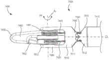
图5-10是根据一个实施例的器械2400的各个部分的示意图。在一些实施例中,器械2400或其中的任何部件可选地是执行外科手术程序的手术系统的部分,并且该部分可以包括操纵器单元、一系列运动联动装置、一系列插管等。器械2400(和本文描述的任何器械)可以用在任何合适的手术系统中,诸如以上示出和描述的MIRS系统1000。器械2400包括腕部组件2500、带2420(其用作张力构件)和工具构件2462。如本文所述,器械2400被构造成使得带2420的运动产生腕部组件2500的运动(如图7所示)、工具构件2462的运动(如图9所示),或腕部组件2500的运动和工具构件2462的运动两者。5-10 are schematic diagrams of various portions of aninstrument 2400 according to one embodiment. In some embodiments,instrument 2400, or any components therein, is optionally part of a surgical system that performs a surgical procedure, and this part may include a manipulator unit, a series of motion linkages, a series of cannulas, and the like. Instrument 2400 (and any instrument described herein) may be used in any suitable surgical system, such asMIRS system 1000 shown and described above.Instrument 2400 includeswrist assembly 2500, strap 2420 (which acts as a tension member), andtool member 2462. As described herein, theinstrument 2400 is configured such that movement of thestrap 2420 produces movement of the wrist assembly 2500 (shown in FIG. 7 ), movement of the tool member 2462 (shown in FIG. 9 ), or movement of thewrist assembly 2500 and movement of thetool member 2462.

腕部组件2500包括近侧的第一连杆2510和远侧的第二连杆2610。第一连杆2510具有近端部分2511和远端部分2512。近端部分2511被联接到轴(未示出)。尽管在图5-图10中未示出轴,但是近端部分2511可以被联接到任何合适的轴,诸如本文中示出和描述的轴5410或轴7410。此外,第一连杆2510的近端部分2511可通过任何合适的机制(例如焊接、过盈配合、粘合剂等)被联接到轴。如下所述,远端部分2512在转动接头处联接到第二连杆2610。以这种方式,第一连杆2510和第二连杆2610形成具有第一旋转轴线A1(其用作俯仰轴线,术语俯仰是任意的)的腕部组件2500。第二连杆可以相对于第一连杆绕第一旋转轴线A1旋转。Wrist assembly 2500 includes a proximalfirst link 2510 and a distalsecond link 2610. Thefirst link 2510 has aproximal portion 2511 and adistal portion 2512.Proximal portion 2511 is coupled to a shaft (not shown). Although a shaft is not shown in Figures 5-10,proximal portion 2511 may be coupled to any suitable shaft, such asshaft 5410 orshaft 7410 shown and described herein. Additionally, theproximal portion 2511 of thefirst link 2510 may be coupled to the shaft by any suitable mechanism (eg, welding, interference fit, adhesive, etc.). As described below, thedistal portion 2512 is coupled to thesecond link 2610 at a swivel joint. In this manner, thefirst link 2510 and thesecond link 2610 form awrist assembly 2500 having a first axis of rotation A1 (which serves as a pitch axis, the term pitch being arbitrary). The second link is rotatable relative to the first link about afirst rotation axis A1.

如图6和图7中所示,第一连杆2510限定与第一旋转轴线A1相交的纵向中心线CL1。参照图8-10,在第一连杆2510中限定第一引导通道2515。带2420的远端部分2422在第一引导通道2515内移动。更具体地,第一连杆2510包括内部引导表面2516和外部引导表面2517,内部引导表面2516和外部引导表面2517均形成第一引导通道2515的边界的一部分。如图10所示,内部引导表面2516的在正交于第一连杆2510的纵向中心线CL1(或第一引导通道2515的纵向中心线)的横截平面内截取的一部分是线性的。类似地,外部引导表面2517的在正交于第一连杆2510的纵向中心线CL1(或第一引导通道2515的纵向中心线)的横截平面内截取的一部分是线性的。如下所述,这种布置允许当第二连杆2610相对于第一连杆2510在第一方向上旋转时,内部引导表面2516沿着线性横截面接触表面(而不是仅在横截面内的单个点处)接触带2420的对应的内部接触表面2425。该布置还允许当第二连杆2610相对于第一连杆2510在与第一方向相反的第二方向上旋转时,外部引导表面2517沿着线性横截面接触表面接触带2420的对应的外部接触表面2426。As shown in FIGS. 6 and 7 , thefirst link 2510 defines a longitudinal centerline CL1 that intersects the first axis of rotation A 1. Referring to FIGS. 8-10 , afirst guide channel 2515 is defined in thefirst link 2510 . Thedistal portion 2422 of thestrap 2420 moves within thefirst guide channel 2515. More specifically, thefirst link 2510 includes aninner guide surface 2516 and anouter guide surface 2517 that each form part of the boundary of thefirst guide channel 2515 . As shown in FIG. 10 , a portion of theinner guide surface 2516 taken in a cross-sectional plane orthogonal to the longitudinal centerline CL1 of the first link 2510 (or the longitudinal centerline of the first guide channel 2515 ) is linear. Similarly, a portion of theouter guide surface 2517 taken in a cross-sectional plane orthogonal to the longitudinal centerline CL1 of the first link 2510 (or the longitudinal centerline of the first guide channel 2515 ) is linear. As described below, this arrangement allows theinner guide surface 2516 to contact the surface along a linear cross-section (rather than just a single within the cross-section) when thesecond link 2610 is rotated in the first direction relative to thefirst link 2510 point) contact the correspondinginner contact surface 2425 of thestrap 2420. This arrangement also allows theouter guide surface 2517 to contact the corresponding outer contact of thestrap 2420 along the linear cross-sectional contact surface when thesecond link 2610 is rotated relative to thefirst link 2510 in a second direction opposite thefirst direction Surface 2426.

参照图6和图7,第一引导通道2515(以及因此其中的带2420的部分)与第一连杆2510的纵向中心线CL1和第一旋转轴线A1偏移距离d1。以这种方式,在带2420上施加张力(由图7中的向近侧指向的箭头AA指示)产生绕第一旋转轴线A1的扭矩,这导致第二连杆2610相对于第一连杆2510旋转,如图7中的箭头BB所示。参照图8和图9,第一引导通道2515(以及因此其中的带2420的部分)与第二旋转轴线A2偏移距离d2。以这种方式,在带2420上施加张力(由图9中的向近侧指向的箭头CC指示)在工具构件2462上产生围绕第二旋转轴线A2的扭矩,这导致工具构件2462相对于第二连杆2610的旋转,如图9中的箭头DD所示。6 and 7, the first guide channel 2515 (and thus the portion of thebelt 2420 therein) is offset from the longitudinal centerline CL1 of thefirst link 2510 and the first axis of rotation A1 by a distance d1 . In this manner, exerting tension on the strap 2420 (indicated by the proximally directed arrow AA in FIG. 7 ) creates a torque about the first axis of rotation A1 , which causes thesecond link 2610 to relative to thefirst link 2510 rotates, as indicated by arrow BB in Figure 7. 8 and 9, the first guide channel 2515 (and thus the portion of thebelt 2420 therein) is offset from thesecond axis of rotation A2 by a distanced2 . In this manner, the application of tension (indicated by the proximally directed arrow CC in FIG. 9 ) on theband 2420 creates a torque on thetool member 2462 about the second axis of rotation A2 , which causes thetool member 2462 to rotate relative to the second axis of rotation A 2 . The rotation of thesecond link 2610 is shown by arrow DD in FIG. 9 .

第二连杆2610具有近端部分2611和远端部分2612。如上所述,近端部分2611可旋转地联接到第一连杆2510的远端部分2512以形成腕部接头。例如,在一些实施例中,近端部分2611可以经由销接头(诸如,在(于2008年7月16日提交的)标题为“Four-Cable Wristwith Solid Surface Cable Channels(具有固体表面缆线通道的四缆线腕部)”的美国专利No.US 8,821,480B2中示出和描述的近侧U形夹220和远侧U形夹230之间的销接头)被联接到远端部分2512,该美国专利的全部内容通过引用整体并入本文。在另一些实施例中,近端部分2611可以经由配合盘表面(诸如,在(于2015年2月20日提交)标题为“MechanicalWrist Joints with Enhanced Range of Motion,and Related Devices and Methods(具有增强的运动范围的机械腕部接头以及相关设备和方法)”的美国专利申请公布No.US2017/0120457A1中示出和描述的类型)被联接到远端部分2512,该美国专利申请公布的全部内容通过引用整体并入本文。Thesecond link 2610 has aproximal portion 2611 and adistal portion 2612. As described above, theproximal portion 2611 is rotatably coupled to thedistal portion 2512 of thefirst link 2510 to form a wrist joint. For example, in some embodiments, theproximal portion 2611 may be provided via pin joints such as those described in (filed Jul. 16, 2008) entitled "Four-Cable Wristwith Solid Surface Cable Channels. The pin joint between the proximal clevis 220 and the distal clevis 230 shown and described in US Patent No. US 8,821,480 B2 for a four-cable wrist)" is coupled to thedistal portion 2512, which US The entire contents of the patents are incorporated herein by reference in their entirety. In other embodiments, theproximal portion 2611 may be provided via a mating disc surface (such as in (filed on February 20, 2015) entitled "MechanicalWrist Joints with Enhanced Range of Motion, and Related Devices and Methods (with Enhanced Range of Motion). Range of motion mechanical wrist joints and related devices and methods)" of the type shown and described in US Patent Application Publication No. US2017/0120457A1) is coupled to thedistal portion 2512, the entire contents of which are incorporated by reference Incorporated herein in its entirety.

第二连杆2610的远端部分2612包括连接器2680,该连接器2680被联接到工具构件2462,使得工具构件2462相对于腕部组件2500绕第二旋转轴线A2旋转。如图5所示,第二旋转轴线A2(也称为偏航轴线或抓握轴线)不平行于第一旋转轴线A1。因此,器械2400提供了多达三个自由度(即,围绕第一旋转轴线A1的俯仰运动、围绕第二旋转轴线A2的偏航旋转以及围绕第二旋转轴线A2的抓握运动)。尽管第二旋转轴线A2被示出为正交于第一旋转轴线A1,但是在另一些实施例中,第二旋转轴线A2可以与第一旋转轴线A1偏移任何合适的角度。连接器2680可以是将工具构件2462可旋转地联接到第二连杆2610以形成工具接头的任何合适的连接器。例如,在一些实施例中,连接器2680可以包括U形夹和销,诸如在(于2008年7月16日提交)标题为“Medical Instrument Electronically Energized Using Drive Cables(使用驱动缆线电子激励的医疗器械)”的美国专利No.US 9,204,923B2中示出和描述的销接头,该美国专利的全部内容通过引用整体并入本文。在另一些实施例中,连接器2680可以包括顺应机构,诸如在(2016年1月26日提交)标题为“Rolling-Contact Joint Mechanismsand Methods(滚动接触接头机构和方法)”的国际专利公开No.WO2016/123139A2中示出和描述的顺应机构,该国际专利公开的全部内容通过引用整体并入本文。Thedistal portion 2612 of thesecond link 2610 includes aconnector 2680 that is coupled to thetool member 2462 such that thetool member 2462 rotates relative to thewrist assembly 2500 about the second axis of rotation A2 . As shown in FIG. 5 , the second axis of rotation A2 (also referred to as the yaw axis or grip axis) is not parallel to the first axis of rotation A1 . Thus, theinstrument 2400 provides up to three degrees of freedom (ie, pitching motion about thefirst axis of rotation A1, yaw rotation about thesecond axis of rotation A2, and grasping motion about thesecond axis of rotation A2) . Although the second axis of rotation A2 is shown as being orthogonal to the first axis of rotation A1 , in other embodiments, the second axis of rotation A2 may be offset from the first axis of rotation A1 by any suitable angle.Connector 2680 may be any suitable connector that rotatably couplestool member 2462 tosecond link 2610 to form a tool joint. For example, in some embodiments,connector 2680 may include a clevis and pin, such as described in (filed Jul. 16, 2008) entitled "Medical Instrument Electronically Energized Using Drive Cables. Instrument)" of US Patent No. US 9,204,923 B2, the entire contents of which are incorporated herein by reference in their entirety. In other embodiments, theconnector 2680 may include a compliant mechanism, such as in International Patent Publication No. (filed January 26, 2016) entitled "Rolling-Contact Joint Mechanisms and Methods". The compliant mechanism shown and described in WO 2016/123139 A2, the entire content of this international patent publication is hereby incorporated by reference in its entirety.

如图7所示,第二连杆2610限定与第一旋转轴线A1相交的纵向中心线CL2。当腕部组件2500处于第一构型(图5和图6)时,第一连杆2510的纵向中心线CL1和第二连杆2610的纵向中心线CL2是共线的(并且在图6中被共同地标识为CL)。当第二连杆2610相对于第一连杆2510旋转(即,俯仰旋转)时,纵向中心线CL1和纵向中心线CL2形成俯仰角。As shown in FIG. 7 , thesecond link 2610 defines a longitudinal centerline CL2 that intersects the first axis of rotation A1 . When thewrist assembly 2500 is in the first configuration (FIGS. 5 and 6), the longitudinal centerline CL1 of thefirst link 2510 and the longitudinal centerline CL2of thesecondlink 2610 are collinear (and are 6 are collectively identified as CL). When thesecond link 2610 rotates relative to the first link 2510 (ie, pitch rotates), the longitudinal centerlineCL1 and the longitudinal centerline CL2 forma pitch angle.

参照图8-9,在第二连杆2610中限定第二引导通道2615。带2420的远端部分2422在第二引导通道2615内移动。尽管未在图10中示出,但是第二连杆2610包括内部引导表面和外部引导表面(分别类似于内部引导表面2516和外部引导表面2517),内部引导表面和外部引导表面均形成第二引导通道2615的边界的一部分。如以上参照第一连杆2515的引导表面所描述的,当第二连杆2610相对于第二连杆2610旋转时,第二连杆2610的内部引导表面和外部引导表面接触带2420的对应表面。参照图6,第二引导通道2615(以及因此其中的带2420的部分)与第二连杆2610的纵向中心线CL1和第一旋转轴线A1偏移距离d1。以这种方式,在带2420上施加张力(由图7中的向近侧指向的箭头AA指示)产生绕第一旋转轴线A1的扭矩,这导致第二连杆2610相对于第一连杆2510的旋转,如图7中的箭头BB所示。参照图8和图9,第二引导通道2615(以及因此其中的带2420的部分)与第二旋转轴线A2偏移距离d2。以这种方式,在带2420上施加张力(由图9中的向近侧指向的箭头CC指示)在工具构件2462上产生围绕第二旋转轴线A2的扭矩,这导致工具构件2462相对于第二连杆2610的旋转,如图9中的箭头DD所示。Referring to FIGS. 8-9 , asecond guide channel 2615 is defined in thesecond link 2610 . Thedistal portion 2422 of thestrap 2420 moves within thesecond guide channel 2615. Although not shown in Figure 10, thesecond link 2610 includes an inner guide surface and an outer guide surface (similar to theinner guide surface 2516 and theouter guide surface 2517, respectively) that each form a second guide A portion of the boundary ofchannel 2615. As described above with reference to the guide surfaces of thefirst link 2515, when thesecond link 2610 is rotated relative to thesecond link 2610, the inner and outer guide surfaces of thesecond link 2610 contact corresponding surfaces of thestrap 2420 . 6, the second guide channel 2615 (and thus the portion of thebelt 2420 therein) is offset from the longitudinal centerline CL1 of thesecond link 2610 and the first axis of rotation A1 by a distance d1 . In this manner, exerting tension on the strap 2420 (indicated by the proximally directed arrow AA in FIG. 7 ) creates a torque about the first axis of rotation A1 , which causes thesecond link 2610 to relative to the first link The rotation of 2510 is shown by arrow BB in FIG. 7 . 8 and 9, the second guide channel 2615 (and thus the portion of thebelt 2420 therein) is offset from thesecond axis of rotation A2 by a distanced2 . In this manner, the application of tension (indicated by the proximally directed arrow CC in FIG. 9 ) on theband 2420 creates a torque on thetool member 2462 about the second axis of rotation A2 , which causes thetool member 2462 to rotate relative to the second axis of rotation A 2 . The rotation of thesecond link 2610 is shown by arrow DD in FIG. 9 .

工具构件2462联接到腕部组件2500并且相对于腕部组件绕第二旋转轴线A2旋转。以这种方式,工具构件2462的远侧部分(例如,接合部分)可以在外科手术过程中接合或操纵目标组织。工具构件2462(或本文描述的任何工具构件)可以是任何合适的医疗工具构件。例如,在一些实施例中,工具构件2462(或本文描述的任何工具构件)可以包括用作抓握器、切割器、组织操纵器等的接合表面。在另一些实施例中,工具构件2462(或本文描述的任何工具构件)可以是用于烧灼程序的通电工具构件。尽管仅示出了一个工具构件2462,但是在另一些实施例中,器械2400包括两个共同执行抓握或剪切功能的运动工具构件。以这种方式,工具构件2462可以形成用于器械2400的末端执行器的一部分。Thetool member 2462 is coupled to thewrist assembly 2500 and rotates relative to the wrist assembly about asecond axis of rotation A2. In this manner, the distal portion (eg, engagement portion) of thetool member 2462 can engage or manipulate target tissue during a surgical procedure. Tool member 2462 (or any tool member described herein) can be any suitable medical tool member. For example, in some embodiments, tool member 2462 (or any tool member described herein) may include an engagement surface that acts as a grasper, cutter, tissue manipulator, or the like. In other embodiments, tool member 2462 (or any tool member described herein) may be an energized tool member for use in a cautery procedure. Although only onetool member 2462 is shown, in other embodiments, theinstrument 2400 includes two motion tool members that collectively perform a grasping or cutting function. In this manner,tool member 2462 may form part of an end effector forinstrument 2400.

带2420具有近端部分2421和远端部分2422。近端部分2421延伸到腕部组件2500的外部、通过轴(未示出)并且联接到致动器(未示出)。致动器可以通过任何合适的机构来使带的近端部分2421运动,以在带的远端部分2422处产生合成的运动(或力)(如图7中的箭头AA和图9中的箭头CC所示)。在一些实施例中,器械2400的后端是马达驱动的,并且因此适用于远程操作手术系统。带2420的远端部分2422在第一引导通道2515和第二引导通道2615内,并且联接到工具构件2462。以这种方式,如本文中所描述的,带2420的运动(或施加到带的力)产生工具构件2462的旋转,第二连杆2610的旋转或工具构件2462和第二连杆2610两者的旋转。带2420的远端部分2422可以通过任何合适的机制联接到工具构件2462。例如,在一些实施例中,远端部分2422通过与工具构件2462的连接部分接合(或接收在其中)的销或突起而联接到工具构件2462。在另一些实施例中,远端部分2422经由粘合剂联接到工具构件2462。在另一些实施例中,带的远端部分2422被缠绕在工具构件2462的皮带轮部分周围。Strap 2420 has aproximal portion 2421 and adistal portion 2422.Proximal portion 2421 extends to the exterior ofwrist assembly 2500 through a shaft (not shown) and is coupled to an actuator (not shown). The actuator may move theproximal portion 2421 of the strap by any suitable mechanism to produce a resultant motion (or force) at thedistal portion 2422 of the strap (see arrows AA in FIG. 7 and arrows in FIG. 9 . CC shown). In some embodiments, the rear end of theinstrument 2400 is motor-driven and thus suitable for use in a teleoperated surgical system. Thedistal end portion 2422 of thestrap 2420 is within thefirst guide channel 2515 and thesecond guide channel 2615 and is coupled to thetool member 2462. In this manner, as described herein, movement of the belt 2420 (or force applied to the belt) produces rotation of thetool member 2462, rotation of thesecond link 2610, or both thetool member 2462 and thesecond link 2610 rotation. Thedistal portion 2422 of thestrap 2420 may be coupled to thetool member 2462 by any suitable mechanism. For example, in some embodiments, thedistal end portion 2422 is coupled to thetool member 2462 by a pin or protrusion that engages with (or is received in) a connecting portion of thetool member 2462. In other embodiments, thedistal portion 2422 is coupled to thetool member 2462 via an adhesive. In other embodiments, thedistal end portion 2422 of the strap is wrapped around the pulley portion of thetool member 2462.

带2420(以及本文所述的任何带)可具有任何合适的形状。例如,尽管图10将带2420示出为具有矩形横截面形状(在正交于带2420的纵向中心线的横截平面内截取),但是在另一些实施例中,带2420可具有任何合适的横截面形状。例如,在一些实施例中,带2420(以及本文所述的任何带)可具有梯形形状。在另一些实施例中,带2420(以及本文所述的任何带)可包括略微弯曲的表面。例如,尽管内部接触表面2425和外部接触表面2426被示出为线性(在正交于带2420的纵向中心线的横截平面内),但是在另一些实施例中,内部接触表面2425、外部接触表面2426或这两者均是弯曲的或“带冠的”。此外,带2420(以及本文所述的任何带)可以由任何合适的材料构造。例如,在一些实施例中,带2420(以及本文所述的任何带)可以由一系列粘合(例如,通过粘合剂)在一起的层压体构造而成。在另一些实施例中,可以通过任何其他合适的方法来接合层压体。层压体可以由任何合适的材料制成,所述材料包括钨、钢或任何合适的聚合物。Strap 2420 (and any straps described herein) can have any suitable shape. For example, although FIG. 10 shows strap 2420 as having a rectangular cross-sectional shape (taken in a cross-sectional plane normal to the longitudinal centerline of strap 2420), in other embodiments strap 2420 may have any suitable cross-sectional shape. For example, in some embodiments, strap 2420 (and any strap described herein) may have a trapezoidal shape. In other embodiments, the strap 2420 (and any strap described herein) can include a slightly curved surface. For example, whileinner contact surface 2425 andouter contact surface 2426 are shown as linear (in a cross-sectional plane normal to the longitudinal centerline of belt 2420), in other embodiments,inner contact surface 2425,outer contact Surface 2426, or both, is curved or "crowned." Furthermore, strap 2420 (and any straps described herein) may be constructed of any suitable material. For example, in some embodiments, tape 2420 (and any tape described herein) may be constructed from a series of laminates that are bonded together (eg, by an adhesive). In other embodiments, the laminates may be joined by any other suitable method. The laminate can be made of any suitable material including tungsten, steel or any suitable polymer.

带2420的使用可以提供适合于外科手术程序(包括微创程序)的低成本的一次性器械。在使用中,器械2400的远端部分提供了多达三个自由度,并且可以在多种不同构型之间移动以执行各种外科手术。例如,在一些情况下,带2420的远端部分2422的运动(如图7中的向近侧指向的箭头AA所示)产生第二连杆2610绕俯仰轴线A1的旋转(如图7中的箭头BB所示)。旋转量、产生期望旋转所需的力以及带2420的移动量可以通过(除其他因素外)带2420与俯仰轴线A1之间的偏移距离d1和带2420的远端部分2422在第一引导通道2515和第二引导通道2615内的曲率(或布线路径(routing))来控制。例如,较大的偏移距离d1将产生较大的力矩臂,但是进而将增加腕部组件2500的整体尺寸。在其他情况下,带2420的远端部分2422的运动(如图9中的向近侧指向的箭头CC所示)产生工具构件2462绕偏航轴线A2的旋转(如图9中的箭头DD所示)。这将产生夹持运动(例如,有两个工具构件的情况)或偏航运动。旋转量、产生期望旋转所需的力以及带2420的移动量可以通过(除其他因素外)带2420与偏航轴线A2之间的偏移距离d2和带2420的远端部分2422在第一引导通道2515和第二引导通道2615内的曲率(或布线路径(routing))来控制。例如,较大的偏移距离d2将产生较大的力矩臂,但是进而将增加腕部组件2500的整体尺寸。The use ofstrap 2420 can provide a low cost disposable instrument suitable for surgical procedures, including minimally invasive procedures. In use, the distal portion of theinstrument 2400 provides up to three degrees of freedom and can be moved between a variety of different configurations to perform various surgical procedures. For example, in some cases, movement of thedistal portion 2422 of the strap 2420 (as shown by the proximally directed arrow AA in FIG. 7 ) produces rotation of thesecond link 2610 about the pitch axis A1 (as shown in FIG. 7 ) arrow BB). The amount of rotation, the force required to produce the desired rotation, and the amount of movement of thebelt 2420 can be determined by (among other factors) the offset distance d1 between thebelt 2420 and the pitch axis A1 and thedistal end portion 2422 of thebelt 2420 at the first The curvature (or routing) within theguide channel 2515 and thesecond guide channel 2615 is controlled. For example, a larger offset distance d1 will result in a larger moment arm, but will in turn increase the overall size of thewrist assembly 2500 . In other cases, movement of thedistal portion 2422 of the band 2420 (as shown by the proximally directed arrow CC in FIG. 9 ) produces a rotation of thetool member 2462 about the yaw axis A2 (as indicated by the arrow DD in FIG. 9 ) shown). This will create a gripping motion (eg, in the case of two tool members) or a yaw motion. The amount of rotation, the force required to produce the desired rotation, and the amount of movement of thebelt 2420 can be determined by (among other factors) the offset distanced2 between thebelt 2420 and the yaw axis A2 and thedistal end portion 2422 of thebelt 2420 at th The curvature (or routing) within aguide channel 2515 and asecond guide channel 2615 is controlled. For example, a larger offset distance d2 will result in a larger moment arm, but will in turn increase the overall size of thewrist assembly 2500 .

尽管第一连杆2510和第二连杆2610被示为具有矩形横截面形状,但是在另一些实施例中,第一连杆2510、第二连杆2610或第一连杆2510和第二连杆2610两者可以具有任何合适的横截面形状。例如,在一些实施例中,第一连杆2510、第二连杆2610或者第一连杆2510和第二连杆2610两者都可以具有基本圆形的横截面形状(即,腕部组件2500可以是基本上是圆柱形的)。Although thefirst link 2510 and thesecond link 2610 are shown as having a rectangular cross-sectional shape, in other embodiments, thefirst link 2510, thesecond link 2610, or thefirst link 2510 and the second link Bothrods 2610 may have any suitable cross-sectional shape. For example, in some embodiments, thefirst link 2510, thesecond link 2610, or both thefirst link 2510 and thesecond link 2610 may have a substantially circular cross-sectional shape (ie, thewrist assembly 2500 can be substantially cylindrical).

尽管第一引导通道2515和第二引导通道2615被示出为分别沿第一连杆2510的纵向中心线CL1和第二连杆2610的纵向中心线CL2是线性的,但是在另一些实施例中,第一引导通道2515、第二引导通道2615或第一引导通道2515和第二引导通道2615两者都可以具有任何合适的纵向形状,以确保带2420穿过腕部组件2500以在第二连杆2610和工具构件2462的整个运动范围内保持期望的张力和长度守恒。例如,图11-17是根据一个实施例的器械3400的各个部分的示意图。器械3400包括腕部组件3500、带3420(其用作张力构件)和工具构件3462。如本文所述,器械3400构造成使得带3420的运动产生腕部组件3500的运动(如图13-14所示)、工具构件3462的运动(未示出,但与以上参照图9所述的运动相似)或腕部组件3500的运动和工具构件3462的运动两者。Although thefirst guide channel 2515 and thesecond guide channel 2615 are shown as being linear along the longitudinal centerline CL1 of thefirst link 2510 and the longitudinal centerline CL2of thesecondlink 2610, respectively, in other implementations For example, thefirst guide channel 2515, thesecond guide channel 2615, or both thefirst guide channel 2515 and thesecond guide channel 2615 may have any suitable longitudinal shape to ensure that thestrap 2420 passes through thewrist assembly 2500 to The desired tension and length conservation is maintained throughout the range of motion of the two-link 2610 andtool member 2462. For example, Figures 11-17 are schematic illustrations of various portions of aninstrument 3400 according to one embodiment.Instrument 3400 includeswrist assembly 3500, strap 3420 (which acts as a tension member), andtool member 3462. As described herein, theinstrument 3400 is configured such that movement of thestrap 3420 produces movement of the wrist assembly 3500 (shown in FIGS. 13-14 ), movement of the tool member 3462 (not shown, but consistent with those described above with reference to FIG. 9 ) movement is similar) or both the movement of thewrist assembly 3500 and the movement of thetool member 3462.

腕部组件3500包括近侧的第一连杆3510和远侧的第二连杆3610。第一连杆3510具有近端部分3511和远端部分3512。近端部分3511联接到轴(未示出)。尽管在图11-17中未示出轴,但是近端部分3511可以联接到任何合适的轴,例如本文中示出和描述的轴5410或轴7410。此外,第一连杆3510的近端部分3511可通过任何合适的机制(例如焊接、过盈配合、粘合剂等)被联接到轴。如下所述,远端部分3512在转动接头处联接到第二连杆3610。以这种方式,第一连杆3510和第二连杆3610形成腕部组件3500,腕部组件3500具有第一旋转轴线A1(其用作俯仰轴线,术语俯仰是任意的),第二连杆3610相对于第一连杆绕第一旋转轴线A1旋转。Wrist assembly 3500 includes a proximalfirst link 3510 and a distalsecond link 3610. Thefirst link 3510 has aproximal portion 3511 and adistal portion 3512.Proximal portion 3511 is coupled to a shaft (not shown). Although a shaft is not shown in Figures 11-17,proximal portion 3511 may be coupled to any suitable shaft, such asshaft 5410 orshaft 7410 shown and described herein. Additionally, theproximal portion 3511 of thefirst link 3510 may be coupled to the shaft by any suitable mechanism (eg, welding, interference fit, adhesive, etc.). As described below, thedistal portion 3512 is coupled to thesecond link 3610 at a swivel joint. In this way, thefirst link 3510 and thesecond link 3610 form awrist assembly 3500 having a first axis of rotation A1 (which serves as a pitch axis, the term pitch is arbitrary), a second link Thelever 3610 rotates about thefirst axis of rotation A1 relative to the first link.

如图13所示,第一连杆3510限定与第一旋转轴线A1相交的纵向中心线CL1。在第一连杆3510中限定第一引导通道3515,并且带3420的远端部分3422在第一引导通道3515中并沿着第一引导通道3515移动。更具体地,如图15-17所示,第一连杆3510包括内部引导表面3516和外部引导表面3517,内部引导表面3516和外部引导表面3517均形成第一引导通道3515的边界的一部分。如图12至图14所示,第一引导通道3515沿着第一连杆3510的纵向中心线CL1弯曲。具体地,如图12所示,内部引导表面3516沿纵向中心线CL1以曲率半径R内部弯曲,并且外部引导表面3517沿纵向中心线CL1以曲率半径R外部弯曲。以这种方式,当第二连杆3610相对于第一连杆3510绕第一旋转轴线A1旋转(即俯仰运动)时,带3420可以接触内部引导表面3516和外部引导表面3517的弯曲部分以在器械3400的致动期间保持期望的弯曲几何形状、带张力等。在一些实施例中,曲率半径R内部不同于曲率半径R外部。而且,尽管内部引导表面3516和外部引导表面3517的曲率被示出为由单个曲率半径(分别为R内部和R外部)限定,但是在另一些实施例中,第一引导通道(或本文描述的任何引导通道)的曲率可以通过多个不同的曲率半径来限定。As shown in FIG. 13 , thefirst link 3510 defines a longitudinal centerline CL1 that intersects the first axis of rotation A 1. Afirst guide channel 3515 is defined in thefirst link 3510, and thedistal end portion 3422 of thestrap 3420 moves in and along thefirst guide channel 3515. More specifically, as shown in FIGS. 15-17 , thefirst link 3510 includes aninner guide surface 3516 and anouter guide surface 3517 that each form part of the boundary of thefirst guide channel 3515 . As shown in FIGS. 12 to 14 , thefirst guide channel 3515 is curved along the longitudinal centerline CL1 of thefirstlink 3510 . Specifically, as shown in FIG. 12, theinner guide surface 3516 is curvedinternally witha radius of curvature R along the longitudinal centerline CL1, and theouter guide surface 3517 is curvedexternally witha radius of curvature R along the longitudinal centerline CL1. In this way, as thesecond link 3610 rotates relative to thefirst link 3510 about thefirst axis of rotation A1 (ie, a pitch motion), thestrap 3420 may contact the curved portions of theinner guide surface 3516 and theouter guide surface 3517 to The desired bend geometry, strap tension, etc. are maintained during actuation of theinstrument 3400. In some embodiments, the radius of curvature Rinner is different from theouter radius R of curvature. Also, although the curvature of theinnerguide surface 3516 and theouterguide surface 3517 are shown as being defined by a single radius of curvature (Rinner and Router, respectively), in other embodiments, the first guide channel (or the The curvature of any guide channel) can be defined by a number of different radii of curvature.

如图15-17所示,内部引导表面3516的在正交于第一连杆3510的纵向中心线CL1(或第一引导通道3515的纵向中心线)的横截平面内截取的一部分是线性的。类似地,外部引导表面3517的在正交于第一连杆3510的纵向中心线CL1(或第一引导通道3515的纵向中心线)的横截平面内截取的一部分是线性的。如下所述,这种布置允许当第二连杆3610相对于第一连杆3510在第一方向上旋转时,内部引导表面3516沿着线性横截面接触表面(而不是仅在横截面内的单个点处)接触带3420的对应的内部接触表面3425。该布置还允许当第二连杆3610相对于第一连杆3510在与第一方向相反的第二方向上旋转时,外部引导表面3517沿着线性横截面接触表面接触带3420的对应的外部接触表面3426。15-17, a portion of theinner guide surface 3516 taken in a cross-sectional plane orthogonal to the longitudinal centerline CL1 of thefirst link 3510 (or the longitudinal centerline of the first guide channel 3515) is linear of. Similarly, a portion of theouter guide surface 3517 taken in a cross-sectional plane orthogonal to the longitudinal centerline CL1 of the first link 3510 (or the longitudinal centerline of the first guide channel 3515 ) is linear. As described below, this arrangement allows theinner guide surface 3516 to contact the surface along a linear cross-section (rather than just a single within the cross-section) when thesecond link 3610 is rotated in the first direction relative to thefirst link 3510 point) contact the correspondinginner contact surface 3425 of thestrap 3420. This arrangement also allows theouter guide surface 3517 to contact the corresponding outer contact of thestrap 3420 along the linear cross-sectional contact surface when thesecond link 3610 is rotated relative to thefirst link 3510 in a second direction opposite thefirst direction Surface 3426.

第一引导通道3515(以及因此其中的带3420的部分)与第一连杆3510的纵向中心线CL1和第一旋转轴线A1偏移。以这种方式,在带3420上施加力(由图13中的箭头EE和图14中的箭头GG指示)产生绕第一旋转轴线A1的扭矩,这导致第二连杆3610相对于第一连杆3510旋转,如图13中的箭头FF和图14中的箭头HH所示。第一引导通道3515(以及因此其中的带3420的部分)与第二旋转轴线A2偏移。以这种方式,在带3420上施加力也在工具构件3462上产生围绕第二旋转轴线A2的扭矩,这导致工具构件3462相对于第二连杆3610的旋转。The first guide channel 3515 (and thus the portion of thebelt 3420 therein) is offset from the longitudinal centerline CL1 of thefirst link 3510 and the first axis of rotation A1 . In this manner, exerting a force on the belt 3420 (indicated by arrows EE in FIG. 13 and arrows GG in FIG. 14 ) creates a torque about the first axis of rotation A1 , which causes thesecond link 3610 to rotate relative to the first Thelink 3510 rotates as shown by arrow FF in FIG. 13 and arrow HH in FIG. 14 . The first guide channel 3515 (and thus the portion of thebelt 3420 therein) is offset from thesecond axis of rotation A2. In this manner, exerting a force on thebelt 3420 also creates a torque on thetool member 3462 about the second axis of rotation A2 , which results in rotation of thetool member 3462 relative to thesecond link 3610 .

第二连杆3610具有近端部分3611和远端部分3612。如上所述,近端部分3611可旋转地联接到第一连杆3510的远端部分3512以形成腕部接头。例如,在一些实施例中,近端部分3611可以经由销接头(诸如,在(于2008年7月16日提交)标题为“Four-Cable Wrist withSolid Surface Cable Channels(具有固体表面缆线通道的四缆线腕部)”的美国专利No.US 8,821,480B2中示出和描述的近侧U形夹220和远侧U形夹230之间的销接头)被联接到远端部分3512,该美国专利的全部内容通过引用整体并入本文。在另一些实施例中,近端部分3611可以经由配合盘表面(诸如,在(于2015年2月20日提交)标题为“MechanicalWrist Joints with Enhanced Range of Motion,and Related Devices and Methods(具有增强的运动范围的机械腕部接头以及相关设备和方法)”的美国专利申请公布No.US2017/0120457A1中示出和描述的类型)被联接到远端部分3512,该美国专利申请公布的全部内容通过引用整体并入本文。Thesecond link 3610 has aproximal portion 3611 and adistal portion 3612. As described above, theproximal portion 3611 is rotatably coupled to thedistal portion 3512 of thefirst link 3510 to form a wrist joint. For example, in some embodiments, theproximal portion 3611 may be accessible via pin joints such as those described in (filed Jul. 16, 2008) titled "Four-Cable Wrist with Solid Surface Cable Channels. The pin joint between the proximal clevis 220 and the distal clevis 230 shown and described in US Patent No. US 8,821,480 B2, "cable wrist)" is coupled to thedistal portion 3512, which US Pat. The entire contents of are incorporated herein by reference in their entirety. In other embodiments, theproximal portion 3611 may be provided via a mating disc surface (such as in (filed on February 20, 2015) entitled "MechanicalWrist Joints with Enhanced Range of Motion, and Related Devices and Methods (with Enhanced Range of Motion). Range of motion mechanical wrist joints and related devices and methods)" of the type shown and described in US Patent Application Publication No. US2017/0120457A1) is coupled to thedistal portion 3512, the entire contents of which are incorporated by reference Incorporated herein in its entirety.

第二连杆3610的远端部分3612包括连接器3680,该连接器3680被联接到工具构件3462,使得工具构件3462相对于腕部组件3500绕第二旋转轴线A2旋转。如图11所示,第二旋转轴线A2不平行于第一旋转轴线A1。轴线A2在工具构件一起旋转时用作偏航轴线(术语偏航是任意的),在工具构件相对于彼此相反地旋转时用作抓握轴线。因此,器械3400提供了多达三个自由度(即,围绕第一旋转轴线A1的俯仰运动、围绕第二旋转轴线A2的偏航旋转以及围绕第二旋转轴线A2的抓握运动)。连接器3680可以是将工具构件3462可旋转地联接到第二连杆3610以形成工具接头的任何合适的连接器。例如,在一些实施例中,连接器3680可以包括U形夹和销,诸如在(于2008年7月16日提交)标题为“Medical InstrumentElectronically Energized Using Drive Cables(使用驱动缆线电子激励的医疗器械)”的美国专利No.US 9,204,923B2中示出和描述的销接头,该美国专利的全部内容通过引用整体并入本文。在另一些实施例中,连接器3680可以包括顺应机构,诸如在(2016年1月26日提交)标题为“Rolling-Contact Joint Mechanisms and Methods(滚动接触接头机构和方法)”的国际专利公开No.WO2016/123139A2中示出和描述的顺应机构,该国际专利公开的全部内容通过引用整体并入本文。与用于销接头的部件相比,使用顺应机构来附接工具构件3462可以允许工具构件具有较少的零件而具有较大的运动范围。Thedistal portion 3612 of thesecond link 3610 includes aconnector 3680 that is coupled to thetool member 3462 such that thetool member 3462 rotates relative to thewrist assembly 3500 about the second axis of rotation A2 . As shown in FIG. 11 , the second axis of rotation A2 is not parallel to the first axis of rotation A1 . Axis A2 serves as the yaw axis (the term yaw is arbitrary) when the tool members are rotated together and as the grip axis when the tool members are rotated opposite each other. Thus, theinstrument 3400 provides up to three degrees of freedom (ie, pitching motion about thefirst axis of rotation A1, yaw rotation about thesecond axis of rotation A2, and gripping motion about thesecond axis of rotation A2) .Connector 3680 may be any suitable connector that rotatably couplestool member 3462 tosecond link 3610 to form a tool joint. For example, in some embodiments,connector 3680 may include a clevis and pin, such as described in (filed Jul. 16, 2008) entitled "Medical Instrument Electronically Energized Using Drive Cables. )" in US Patent No. US 9,204,923 B2, the entire contents of which are incorporated herein by reference in their entirety. In other embodiments, theconnector 3680 may include a compliant mechanism, such as in International Patent Publication No. (filed January 26, 2016) entitled "Rolling-Contact Joint Mechanisms and Methods" . The compliant mechanism shown and described in WO 2016/123139 A2, the entire content of this international patent publication is hereby incorporated by reference in its entirety. Using a compliant mechanism to attach thetool member 3462 may allow the tool member to have fewer parts and a greater range of motion than components used for pin joints.

如图13所示,第二连杆3610限定与第一旋转轴线A1相交的纵向中心线CL2。当腕部组件3500处于第一构型(图11和图12)时,第一连杆3510的纵向中心线CL1和第二连杆3610的纵向中心线CL2是共线的。当第二连杆3610相对于第一连杆3510旋转(即,俯仰运动)时,纵向中心线CL1和纵向中心线CL2形成俯仰角(如图13和图14中所示)。As shown in FIG. 13 , thesecond link 3610 defines a longitudinal centerline CL2 that intersects the first axis of rotation A1 . When thewrist assembly 3500 is in the first configuration ( FIGS. 11 and 12 ), the longitudinal centerline CL1 of thefirst link 3510 and the longitudinal centerline CL2of thesecondlink 3610 are collinear. When thesecond link 3610 is rotated (ie, pitched) relative to thefirst link 3510, the longitudinal centerline CL1 and the longitudinal centerline CL2 forma pitch angle (as shown in FIGS.13 and 14 ).

参照图12-14,在第二连杆3610中限定第二引导通道3615。带3420的远端部分3422在第二引导通道3615内移动。尽管未标识,但是第二连杆3610包括内部引导表面和外部引导表面(分别类似于内部引导表面3516和外部引导表面3517),内部引导表面和外部引导表面均形成第二引导通道3615的边界的一部分。第二引导通道3615沿着第二连杆3610的纵向中心线CL2弯曲。具体地,尽管未标识,但是内部引导表面沿着纵向中心线CL2以一曲率半径弯曲,并且外部引导表面沿着纵向中心线CL2以一曲率半径弯曲。以此方式,当第二连杆3610相对于第一连杆3510绕第一旋转轴线A1旋转(即俯仰运动)时,带3420能够接触第二连杆3610的内部引导表面和外部引导表面的弯曲部分以在器械3400的致动期间保持期望的弯曲几何形状、带张力等。12-14, asecond guide channel 3615 is defined in thesecond link 3610. Thedistal portion 3422 of thestrap 3420 moves within thesecond guide channel 3615. Although not identified,second link 3610 includes an inner guide surface and an outer guide surface (similar toinner guide surface 3516 andouter guide surface 3517 , respectively) that each form a boundary ofsecond guide channel 3615 part. Thesecond guide channel 3615 is curved along the longitudinal centerline CL2 of thesecond link 3610 . Specifically, although not identified, the inner guide surface is curved with a radius of curvature along the longitudinal centerlineCL2 , and the outer guide surface is curved with a radius of curvature along the longitudinal centerlineCL2 . In this way, when thesecond link 3610 rotates (ie, pitches) about thefirst rotation axis A1 relative to thefirst link 3510, thebelt 3420 can contact the inner and outer guide surfaces of thesecond link 3610. The curved portion to maintain the desired curved geometry, strap tension, etc. during actuation of theinstrument 3400.

如以上参照第一连杆3515的引导表面所描述的,当第二连杆3610相对于第二连杆3610旋转时,第二连杆3610的内部引导表面和外部引导表面接触带3420的对应表面。而且,第二引导通道3615(以及因此其中的带3420的部分)与第二连杆3610的纵向中心线CL2和第一旋转轴线A1偏移。以这种方式,在带3420上施加力产生绕第一旋转轴线A1的扭矩,这导致第二连杆3610相对于第一连杆3510的旋转。第二引导通道3615(以及因此其中的带3420的部分)与第二旋转轴线A2偏移。以这种方式,在带3420上施加力在工具构件3462上产生围绕第二旋转轴线A2的扭矩,这导致工具构件3462相对于第二连杆3610的旋转。As described above with reference to the guide surfaces of thefirst link 3515, when thesecond link 3610 is rotated relative to thesecond link 3610, the inner and outer guide surfaces of thesecond link 3610 contact corresponding surfaces of thestrap 3420 . Also, the second guide channel 3615 (and thus the portion of thebelt 3420 therein) is offset from the longitudinal centerline CL2 of thesecond link 3610 and the first axis of rotation A1 . In this manner, exerting a force on thebelt 3420 creates a torque about the first axis of rotation A1 , which results in rotation of thesecond link 3610 relative to thefirst link 3510 . The second guide channel 3615 (and thus the portion of thebelt 3420 therein) is offset from thesecond axis of rotation A2. In this manner, exerting a force on thebelt 3420 creates a torque on thetool member 3462 about the second axis of rotation A2 , which results in rotation of thetool member 3462 relative to thesecond link 3610 .

工具构件3462联接到腕部组件3500并且相对于腕部组件绕第二旋转轴线A2旋转。以这种方式,工具构件3462的远侧部分(例如,接合部分)可以在外科手术过程中接合或操纵目标组织。工具构件3462(或本文描述的任何工具构件)可以是任何合适的医疗工具构件。例如,在一些实施例中,工具构件3462(或本文描述的任何工具构件)可以包括用作抓握器、切割器、组织操纵器等的接合表面。在另一些实施例中,工具构件3462(或本文描述的任何工具构件)可以是用于烧灼程序的通电工具构件。尽管仅示出了一个工具构件3462,但是在另一些实施例中,器械3400包括两个共同执行抓握或剪切功能的运动工具构件。以这种方式,工具构件3462可以形成用于器械3400的末端执行器的一部分。Tool member 3462 is coupled towrist assembly 3500 and rotates relative to the wrist assembly about asecond axis of rotation A2. In this manner, the distal portion (eg, engagement portion) of thetool member 3462 can engage or manipulate target tissue during a surgical procedure. Tool member 3462 (or any tool member described herein) can be any suitable medical tool member. For example, in some embodiments, tool member 3462 (or any tool member described herein) may include an engagement surface that acts as a grasper, cutter, tissue manipulator, or the like. In other embodiments, the tool member 3462 (or any tool member described herein) may be an energized tool member for a cautery procedure. Although only onetool member 3462 is shown, in other embodiments, theinstrument 3400 includes two motion tool members that collectively perform a grasping or cutting function. In this manner,tool member 3462 may form part of an end effector forinstrument 3400.

带3420具有近端部分3421和远端部分3422。近端部分3421延伸到腕部组件3500的外部、通过轴(未示出)并且联接到致动器(未示出)。致动器可以通过任何合适的机构来使带的近端部分3421运动,以在带的远端部分3422处产生合成的运动(或力)(如图13中的箭头EE和图14中的箭头GG所示)。带3420的远端部分3422在第一引导通道3515和第二引导通道3615内,并且联接到工具构件3462。以这种方式,如本文中所描述的,带3420的运动(或施加到带的力)产生工具构件3462的旋转、第二连杆3610的旋转,或工具构件3462和第二连杆3610两者的旋转。带3420的远端部分3422可以通过任何合适的机制联接到工具构件3462。例如,在一些实施例中,远端部分3422通过与工具构件3462的连接部分接合(或容纳在其中)的销或突起而联接到工具构件3462。在另一些实施例中,远端部分3422经由粘合剂联接到工具构件3462。在另一些实施例中,带的远端部分3422能够被缠绕在工具构件3462的皮带轮部分周围。Strap 3420 has aproximal portion 3421 and adistal portion 3422.Proximal portion 3421 extends to the exterior ofwrist assembly 3500 through a shaft (not shown) and is coupled to an actuator (not shown). The actuator may move theproximal portion 3421 of the strap by any suitable mechanism to produce a resultant motion (or force) at thedistal portion 3422 of the strap (see arrows EE in Figure 13 and arrows in Figure 14). GG shown). Thedistal end portion 3422 of thestrap 3420 is within thefirst guide channel 3515 and thesecond guide channel 3615 and is coupled to thetool member 3462. In this manner, movement of the belt 3420 (or force applied to the belt) produces rotation of thetool member 3462, rotation of thesecond link 3610, or both thetool member 3462 and thesecond link 3610, as described herein. the rotation of the person. Thedistal portion 3422 of thestrap 3420 may be coupled to thetool member 3462 by any suitable mechanism. For example, in some embodiments, thedistal end portion 3422 is coupled to thetool member 3462 by a pin or protrusion that engages with (or is received in) a connecting portion of thetool member 3462. In other embodiments, thedistal portion 3422 is coupled to thetool member 3462 via an adhesive. In other embodiments, thedistal end portion 3422 of the strap can be wrapped around the pulley portion of thetool member 3462.

带3420(以及本文所述的任何带)可具有任何合适的形状。此外,带3420(以及本文所述的任何带)可以由任何合适的材料构造。例如,在一些实施例中,带3420(以及本文所述的任何带)可以由一系列粘合(例如,通过粘合剂)在一起的层压体构造而成。在另一些实施例中,可以通过任何其他合适的方法来接合层压体。层压体可以由任何合适的材料制成,所述材料包括钨、钢或任何合适的聚合物。Band 3420 (and any band described herein) can have any suitable shape. Furthermore, strap 3420 (and any strap described herein) may be constructed of any suitable material. For example, in some embodiments, tape 3420 (and any tape described herein) may be constructed from a series of laminates that are bonded together (eg, by an adhesive). In other embodiments, the laminates may be joined by any other suitable method. The laminate can be made of any suitable material including tungsten, steel or any suitable polymer.

带3420的使用可以提供适合于外科手术程序的低成本的一次性器械。在使用中,器械3400的远端部分提供了多达三个自由度,并且可以在多种不同构型之间移动以执行各种外科手术操作。例如,在一些情况下,第二连杆3610可以在第一方向上绕俯仰轴线A1旋转。如图13所示,如箭头EE所示的带3420的运动(或向其施加力)产生第二连杆3610相对于第一连杆3510在第一方向上的旋转(由箭头FF所示)。参照图16,在旋转期间,带3420的内部接触表面3425接触第一连杆3510的内部引导表面3516。具体地,内部接触表面3425可以缠绕在弯曲的内部引导表面3516周围(即,可以保持内部接触表面3425和内部引导表面3516之间的接触),以确保在带3420中保持期望的张力,并且确保远端部分3422和近端部分3421之间的运动(即,联接到致动器)在第二连杆3610和工具构件3462的整个运动范围期间保持不变。如图14所示,如箭头GG所示的带3420的运动(或对其施加力)产生第二连杆3610相对于第一连杆3510在第一方向上的旋转(沿箭头HH所示)。参照图17,带3420的外部接触表面3426接触第一连杆3510的外部引导表面3517。具体地,外部接触表面3417可以缠绕在弯曲的外部引导表面3517上(即,可以保持外部接触表面3426和外部引导表面3517之间的接触),以确保在带3420内保持期望的张力,并且确保远端部分3422和近端部分3421之间的运动(即,联接到致动器)在第二连杆3610和工具构件3462的整个运动范围期间保持不变。The use ofstrap 3420 can provide a low cost disposable instrument suitable for surgical procedures. In use, the distal portion of theinstrument 3400 provides up to three degrees of freedom and can be moved between a variety of different configurations to perform various surgical operations. For example, in some cases, thesecond link 3610 may rotate about the pitch axis A1 in thefirst direction. As shown in FIG. 13, movement of the band 3420 (or application of a force to it) as indicated by arrows EE produces rotation of thesecond link 3610 relative to thefirst link 3510 in a first direction (illustrated by arrows FF) . 16, during rotation, theinner contact surface 3425 of thebelt 3420 contacts theinner guide surface 3516 of thefirst link 3510. Specifically,inner contact surface 3425 may wrap around curved inner guide surface 3516 (ie, contact betweeninner contact surface 3425 andinner guide surface 3516 may be maintained) to ensure that desired tension is maintained instrap 3420, and to ensure Movement between thedistal portion 3422 and the proximal portion 3421 (ie, coupling to the actuator) remains constant during the entire range of motion of thesecond link 3610 and thetool member 3462 . As shown in FIG. 14, movement of the strap 3420 (or application of a force to it) as indicated by arrows GG produces rotation of thesecond link 3610 relative to thefirst link 3510 in a first direction (shown along arrow HH) . Referring to FIG. 17 , theouter contact surface 3426 of thebelt 3420 contacts theouter guide surface 3517 of thefirst link 3510 . Specifically, outer contact surface 3417 may wrap around curved outer guide surface 3517 (ie, contact betweenouter contact surface 3426 andouter guide surface 3517 may be maintained) to ensure that desired tension is maintained withinstrap 3420, and to ensure Movement between thedistal portion 3422 and the proximal portion 3421 (ie, coupling to the actuator) remains constant during the entire range of motion of thesecond link 3610 and thetool member 3462 .

在使用中,在一些实施例中,带(例如,带3420)的第一部分被缠绕在腕部组件的一个或多个引导表面(例如,内部引导表面3516)上,带的第二部分被缠绕在工具构件(例如,工具构件3462)的一部分(例如,皮带轮部分)上。在这样的实施例中,带被构造成具有足够的强度以在腕部组件或工具构件上施加期望的扭矩或力,同时还具有足够的柔韧性以顺应(或包裹)器械内的各种结构。本文所述的带的柔韧性(或刚度)是带的广泛特性,因此取决于带的形成材料和带的某些物理特性(例如,横截面形状、长度、边界条件等)。例如,可以通过由具有期望的弹性模量、挠曲模量和/或硬度的材料选择性地构造带来增加或减小本文所述的任何带的柔韧性。例如,例如可以通过构造具有相对低的弹性模量的材料的带来增加带的柔韧性。在一些实施例中,例如可以通过构造较薄的层压体的带来增加带的柔韧性。也可以通过改变对象的物理特性,例如对象的形状或横截面面积,来增加或减小本文所述的任何带的柔韧性。例如,具有长度和横截面面积的带可以比具有相同长度但是横截面面积较小的另一带具有更大的刚度。因此,可以通过减小尺寸和/或改变带的形状或取向来增加带的柔韧性。同样,带刚度可以通过改变所使用的层压体的数量来改变。In use, in some embodiments, a first portion of the strap (eg, strap 3420) is wrapped around one or more guide surfaces (eg, inner guide surface 3516) of the wrist assembly and a second portion of the strap is wrapped around On a portion (eg, pulley portion) of a tool member (eg, tool member 3462). In such an embodiment, the strap is constructed with sufficient strength to exert the desired torque or force on the wrist assembly or tool member, while also being flexible enough to conform to (or wrap around) various structures within the instrument . The flexibility (or stiffness) of the tapes described herein is a broad property of the tape and thus depends on the material from which the tape is formed and certain physical properties of the tape (eg, cross-sectional shape, length, boundary conditions, etc.). For example, the flexibility of any of the tapes described herein can be increased or decreased by selectively constructing the tape from a material having a desired elastic modulus, flexural modulus, and/or hardness. For example, the flexibility of the belt can be increased, for example, by constructing the belt of a material having a relatively low elastic modulus. In some embodiments, the flexibility of the belt can be increased, for example, by constructing the belts of thinner laminates. The flexibility of any of the straps described herein can also be increased or decreased by altering the physical properties of the object, such as the shape or cross-sectional area of the object. For example, a belt of length and cross-sectional area may have greater stiffness than another belt of the same length but a smaller cross-sectional area. Thus, the flexibility of the belt can be increased by reducing the size and/or changing the shape or orientation of the belt. Likewise, belt stiffness can be varied by varying the number of laminates used.

诸如本文所述的任何带的细长对象的刚度(或相反,柔韧性)可以通过其挠曲刚度来表征。带的挠曲刚度可用于表征带在给定力下偏斜的容易程度(例如,当沿着本文所述的器械内的弯曲路径缠绕或移动时带偏斜的容易程度)。挠曲刚度可以用数学式表示,如下所示:The stiffness (or conversely, flexibility) of an elongated object, such as any of the belts described herein, can be characterized by its flexural stiffness. The flexural stiffness of the strap can be used to characterize how easily the strap deflects under a given force (eg, how easily the strap deflects when wrapped or moved along a curved path within the instruments described herein). The flexural stiffness can be expressed mathematically as follows:

(1)

Figure BDA0002490904450000231
(1)
Figure BDA0002490904450000231

其中,k是带的挠曲刚度,E是构成带的材料的弹性模量,I是带的面积惯性矩(areamoment of inertia)(以下定义),以及L是带的长度。因此,对于给定的带长度,可以通过减小带的弹性模量和面积惯性矩来减小刚度(即,可以增加柔韧性)。矩形横截面形状的面积惯性矩被表示如下:where k is the flexural stiffness of the belt, E is the elastic modulus of the material that makes up the belt, I is the area moment of inertia of the belt (defined below), and L is the length of the belt. Thus, for a given belt length, stiffness can be reduced (ie, flexibility can be increased) by reducing the elastic modulus and area moment of inertia of the belt. The area moment of inertia for a rectangular cross-sectional shape is expressed as:

(2)

Figure BDA0002490904450000232
(2)
Figure BDA0002490904450000232

其中,x是带弯曲所围绕的轴线,b是与x轴线平行的矩形边的长度(即矩形的“底”),h是正交于x轴线的矩形边的长度(即矩形的“高”)。从该方程式可以明显看出,当底是两侧中的较长者时,矩形的面积惯性矩最低。换句话说,通过确保横截面形状被定向成产生围绕所需弯曲轴线的最小可能的面积惯性矩,可以最大化本文所述的任何带的柔韧性。而且,通过构造附加的更薄的层压体,可以在不降低强度的情况下增加带的柔韧性。where x is the axis about which the tape bends, b is the length of the side of the rectangle parallel to the x-axis (i.e. the "base" of the rectangle), and h is the length of the side of the rectangle that is orthogonal to the x-axis (i.e. the "height" of the rectangle ). It is evident from this equation that the area moment of inertia of a rectangle is lowest when the base is the longer of the two sides. In other words, the flexibility of any belt described herein can be maximized by ensuring that the cross-sectional shape is oriented to produce the smallest possible area moment of inertia about the desired bending axis. Also, by constructing additional thinner laminates, the flexibility of the belt can be increased without reducing strength.

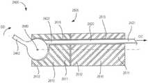
因此,在一些实施例中,器械可以包括沿其纵向中心线扭转的带,使得(沿纵向中心线的各个位置处的)横截面形状处于第一取向以产生绕第一轴线的低面积惯性矩,并且处于第二取向以产生绕第二轴线的低面积惯性矩。这种布置可以允许使单个带变形,以维持围绕两个或更多个不同的轴线(例如,俯仰轴线和偏航轴线)的期望的柔韧性。例如,图18示出了根据一个实施例的器械4400的一部分的截面图。器械4400包括腕部组件4500、带4420和工具构件4462。图19-21是在正交于带4420的纵向中心线CL的平面内截取的带4420的各个部分的截面图。器械4400被构造成使得带4420的运动产生腕部组件4500围绕俯仰轴线A1的运动、工具构件4462围绕偏航轴线A2的运动,或腕部组件4500的运动和工具构件4462的运动两者。Thus, in some embodiments, the instrument may include a strap twisted along its longitudinal centerline such that the cross-sectional shape (at various locations along the longitudinal centerline) is in a first orientation to produce a low-area moment of inertia about the first axis , and in the second orientation to produce a low area moment of inertia about the second axis. This arrangement may allow a single strap to be deformed to maintain a desired flexibility about two or more different axes (eg, pitch and yaw axes). For example, Figure 18 shows a cross-sectional view of a portion of aninstrument 4400 according to one embodiment.Instrument 4400 includeswrist assembly 4500,strap 4420, andtool member 4462. 19-21 are cross-sectional views of various portions of thebelt 4420 taken in a plane orthogonal to the longitudinal centerline CL of thebelt 4420.Instrument 4400 is configured such that movement ofstrap 4420 produces movement ofwrist assembly 4500 about pitch axis A1, movementof tool member 4462 about yaw axis A2, orboth movement ofwrist assembly 4500 and movement oftool member 4462 .

腕部组件4500包括近侧的第一连杆4510和远侧的第二连杆4610。第一连杆4510具有近端部分和远端部分。第一连杆4510的近端部分以与以上参照腕部组件2500和腕部组件3500所述的相似的方式联接到轴(未示出,但是与本文所述的任何轴相似)。远端部分在转动接头处联接到第二连杆4610。以此方式,第一连杆4510和第二连杆4610形成具有第一旋转轴线A1(其用作俯仰轴线,术语俯仰是任意的)的腕部组件4500,第二连杆4610相对于第一连杆绕第一旋转轴线A1旋转。Wrist assembly 4500 includes a proximalfirst link 4510 and a distalsecond link 4610. Thefirst link 4510 has a proximal portion and a distal portion. The proximal portion of thefirst link 4510 is coupled to a shaft (not shown, but similar to any shaft described herein) in a manner similar to that described above with reference towrist assembly 2500 andwrist assembly 3500. The distal portion is coupled to thesecond link 4610 at a swivel joint. In this way, thefirst link 4510 and thesecond link 4610 form awrist assembly 4500 having a first axis of rotation A1 (which serves as a pitch axis, the term pitch being arbitrary), thesecond link 4610 being relative to the first A link rotates about thefirst rotation axis A1.

第二连杆4610具有近端部分4611和远端部分4612。如上所述,近端部分4611可旋转地联接到第一连杆4510。第二连杆4610的近端部分4611和第一连杆4510的远端部分可以联接在一起以形成任何合适的腕部接头。例如,在一些实施例中,第二连杆4610可以经由本文示出和描述的类型的销接头联接到第一连杆4510。在另一些实施例中,第二连杆4610可经由本文所示和所述类型的配合盘表面联接到第一连杆4510。第二连杆4610的远端部分4612联接到工具构件4462的皮带轮部分4467,使得工具构件4462相对于腕部组件4500绕第二旋转轴线A2旋转。如图18所示,第二旋转轴线A2不平行于第一旋转轴线A1。轴线A2在工具构件一起旋转时用作偏航轴线(术语偏航是任意的),在工具构件相对于彼此相反地旋转时用作抓握轴线。因此,器械4400提供了多达三个自由度(即,围绕第一旋转轴线A1的俯仰运动、围绕第二旋转轴线A2的偏航旋转以及围绕第二旋转轴线A2的抓握运动)。工具构件4462可以经由任何合适的接头可旋转地联接到第二连杆4610。例如,在一些实施例中,第二连杆4610可以包括U形夹和销,诸如在(于2008年7月16日提交)标题为“Medical InstrumentElectronically Energized Using Drive Cables(使用驱动缆线电子激励的医疗器械)”的美国专利No.US 9,204,923B2中示出和描述的销接头,该美国专利的全部内容通过引用整体并入本文。在另一些实施例中,第二连杆4610可以包括顺应机构,诸如在(2016年1月26日提交)标题为“Rolling-Contact Joint Mechanisms and Methods(滚动接触接头机构和方法)”的国际专利公开No.WO2016/123139A2中示出和描述的顺应机构,该国际专利公开的全部内容通过引用整体并入本文。Thesecond link 4610 has aproximal portion 4611 and adistal portion 4612. As described above,proximal portion 4611 is rotatably coupled tofirst link 4510. Theproximal portion 4611 of thesecond link 4610 and the distal portion of thefirst link 4510 may be coupled together to form any suitable wrist joint. For example, in some embodiments, thesecond link 4610 may be coupled to thefirst link 4510 via a pin joint of the type shown and described herein. In other embodiments, thesecond link 4610 may be coupled to thefirst link 4510 via a mating disc surface of the type shown and described herein. Thedistal end portion 4612 of thesecond link 4610 is coupled to thepulley portion 4467 of thetool member 4462 such that thetool member 4462 rotates relative to thewrist assembly 4500 about the second axis of rotation A2 . As shown in FIG. 18 , the second axis of rotation A2 is not parallel to the first axis of rotation A1 . Axis A2 serves as the yaw axis (the term yaw is arbitrary) when the tool members are rotated together and as the grip axis when the tool members are rotated opposite each other. Thus, theinstrument 4400 provides up to three degrees of freedom (ie, pitch motion about thefirst axis of rotation A1, yaw rotation about thesecond axis of rotation A2, and grip motion about thesecond axis of rotation A2) .Tool member 4462 may be rotatably coupled tosecond link 4610 via any suitable joint. For example, in some embodiments, thesecond link 4610 may include a clevis and pin, such as described in (filed Jul. 16, 2008) entitled "Medical Instrument Electronically Energized Using Drive Cables. Medical Device)", US Patent No. US 9,204,923 B2, which is incorporated herein by reference in its entirety. In other embodiments, thesecond link 4610 may include a compliant mechanism, such as in the International Patent (filed January 26, 2016) entitled "Rolling-Contact Joint Mechanisms and Methods" The compliant mechanism shown and described in Publication No. WO2016/123139A2, the entire content of which is incorporated herein by reference in its entirety.

如图所示,第二连杆4610限定引导通道4615,带4420的一部分4422可移动地布置在该引导通道中。在一些实施例中,第二连杆4610包括内部引导表面和外部引导表面(分别类似于内部引导表面3516和外部引导表面3517),内部引导表面和外部引导表面均形成引导通道4615的边界的一部分。而且,在一些实施例中,引导通道4615沿着第二连杆4610的纵向中心线弯曲。以这种方式,当第二连杆4610相对于第一连杆4510绕第一旋转轴线A1旋转(即俯仰运动)时,带4420可以接触第二连杆4610的内部引导表面和外部引导表面的弯曲部分以在器械4400的致动期间保持期望的弯曲几何形状、带张力等。As shown, thesecond link 4610 defines aguide channel 4615 in which aportion 4422 of thestrap 4420 is movably disposed. In some embodiments,second link 4610 includes an inner guide surface and an outer guide surface (similar toinner guide surface 3516 andouter guide surface 3517 , respectively) that each form part of the boundary ofguide channel 4615 . Also, in some embodiments, theguide channel 4615 is curved along the longitudinal centerline of thesecond link 4610. In this way, when thesecond link 4610 rotates relative to thefirst link 4510 about thefirst axis of rotation A1 (ie, a pitch motion), thestrap 4420 can contact the inner and outer guide surfaces of thesecond link 4610 to maintain the desired bend geometry, strap tension, etc. during actuation of theinstrument 4400.

工具构件4462联接到腕部组件4500,并且包括接触部分4464和皮带轮部分4467。接触部分4464被构造成在外科手术过程中接合或操纵目标组织。例如,在一些实施例中,接触部分4464可以包括用作抓握器、切割器、组织操纵器等的接合表面。在另一些实施例中,接触部分4464可以是用于烧灼程序的通电工具构件。如上所述,皮带轮部分4467可旋转地联接到第二连杆4610,使得工具构件4462相对于腕部组件4500绕第二旋转轴线A2旋转,如箭头JJ所示。以这种方式,工具构件4462的接触部分4464可以在外科手术过程中接合或操纵目标组织。工具构件4462(或本文描述的任何工具构件)可以是任何合适的医疗工具构件。而且,尽管仅示出了一个工具构件4462,但是在另一些实施例中,器械4400包括两个运动的工具构件,其协同执行抓握或剪切功能。以这种方式,工具构件4462可以形成用于器械4400的末端执行器的一部分。Tool member 4462 is coupled towrist assembly 4500 and includes acontact portion 4464 and apulley portion 4467 .Contact portion 4464 is configured to engage or manipulate target tissue during a surgical procedure. For example, in some embodiments, thecontact portion 4464 may include an engagement surface for use as a grasper, cutter, tissue manipulator, or the like. In other embodiments, thecontact portion 4464 may be an energized tool member for a cautery procedure. As described above, thepulley portion 4467 is rotatably coupled to thesecond link 4610 such that thetool member 4462 rotates relative to thewrist assembly 4500 about thesecond axis of rotation A2, as indicated by arrow JJ. In this manner, the contactingportion 4464 of thetool member 4462 can engage or manipulate target tissue during a surgical procedure. Tool member 4462 (or any tool member described herein) can be any suitable medical tool member. Also, although only onetool member 4462 is shown, in other embodiments, theinstrument 4400 includes two moving tool members that cooperate to perform a grasping or cutting function. In this manner,tool member 4462 may form part of an end effector forinstrument 4400.

带4420(其用作张力构件)限定纵向中心线CL并且具有第一带部分4421、第二带部分4422和第三带部分4423。第三带部分4423位于第二带部分4422和第一带部分4421之间。第一带部分4421在引导通道4615内,并且延伸到第一连杆构件4510中。在一些实施例中,带4420可以包括第四带部分(即,近端部分),第四带部分延伸到腕部组件4500的外部、通过轴(未示出)并且联接到致动器(未示出)。致动器可以通过任何合适的机构使带4420运动,以在第一带部分4421处产生合成的运动(或力)(如图18中的箭头II所示)。第二带部分4422联接到工具构件4462。具体地,第二带部分4422联接到工具构件4462的皮带轮部分4467(或缠绕在其一部分周围)。以这种方式,如本文所述,带4420的运动(或施加到其上的力)产生工具构件4462的旋转(如箭头JJ所示)、第二连杆4610的旋转或工具构件4462和第二连杆4610两者的旋转。带4420的第二带部分4422可以通过任何合适的机构联接到工具构件4462。例如,在一些实施例中,第二带部分4422可以通过与皮带轮部分4467的连接部分接合(或被接收在其中)的销或突起联接到工具构件4462。在另一些实施例中,第二带部分4422可以通过粘合剂被联接到皮带轮部分4467。The strap 4420 (which acts as a tension member) defines a longitudinal centerline CL and has afirst strap portion 4421 , asecond strap portion 4422 and athird strap portion 4423 . Thethird strap portion 4423 is located between thesecond strap portion 4422 and thefirst strap portion 4421 . Thefirst strap portion 4421 is within theguide channel 4615 and extends into thefirst link member 4510. In some embodiments,strap 4420 can include a fourth strap portion (ie, a proximal portion) that extends outside ofwrist assembly 4500, through a shaft (not shown), and is coupled to an actuator (not shown) Shows). The actuator may move thestrap 4420 by any suitable mechanism to produce a resultant motion (or force) at the first strap portion 4421 (as shown by arrow II in Figure 18). Thesecond strap portion 4422 is coupled to thetool member 4462 . Specifically, thesecond belt portion 4422 is coupled to (or wrapped around a portion of) thepulley portion 4467 of thetool member 4462 . In this manner, as described herein, movement of the belt 4420 (or a force applied to it) produces rotation of the tool member 4462 (as indicated by arrows JJ), rotation of thesecond link 4610 or thetool member 4462 and thesecond link 4610. Rotation of bothlinks 4610. Thesecond strap portion 4422 of thestrap 4420 may be coupled to thetool member 4462 by any suitable mechanism. For example, in some embodiments, thesecond belt portion 4422 may be coupled to thetool member 4462 by a pin or protrusion that engages with (or is received in) a connecting portion of thepulley portion 4467 . In other embodiments, thesecond belt portion 4422 may be coupled to thepulley portion 4467 by adhesive.

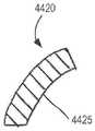
如图所示,带4420沿其纵向中心线CL在第一带部分4421和第二带部分4422之间扭转。如参照图19-21类似所述,带4420沿其纵向中心线CL成角度地变形,使得第一带部分4421处的接触表面4425的取向不同于第二带部分4422处的接触表面4425的取向。如图20所示,接触表面4425在第三带部分4423处的取向和形状与在第一带部分4421或第二带部分4422处的不同。作为描述带4420的扭转的另一种方式,带4420在正交于纵向中心线CL的平面内的横截面形状由长轴表征。尽管术语“长轴”通常在椭圆形的背景下使用,但是当在本文中的矩形(或梯形)形状的背景下使用时,术语“长轴”是穿过相对侧边的中心点的横截面形状的较长轴线。参照图19-21,第一带部分4421内的长轴AM1与第二带部分4422内的长线AM2处于不同的角度取向。通过这种方式,第一带部分4421处的接触表面4425可以接触引导表面或可以围绕第一旋转轴线A1弯曲,并且第二带部分4422处的接触表面4425可以缠绕在皮带轮部分4467周围或围绕第二旋转轴线A2弯曲。通过扭转,使带4420围绕期望的变形轴线的面积惯性矩最小化。因此,带4420的柔韧性在第一带部分4421最大化(以促进第二连杆构件4610绕俯仰轴线A1的旋转)以及在第二带部分4422处最大化(以促进工具构件4462绕偏航轴线A2的旋转)。As shown, thestrap 4420 twists between thefirst strap portion 4421 and thesecond strap portion 4422 along its longitudinal centerline CL. As similarly described with reference to FIGS. 19-21 , thebelt 4420 is angularly deformed along its longitudinal centerline CL such that the orientation of thecontact surface 4425 at thefirst belt portion 4421 is different from the orientation of thecontact surface 4425 at thesecond belt portion 4422 . As shown in FIG. 20 , the orientation and shape of thecontact surface 4425 at thethird strap portion 4423 is different from that at thefirst strap portion 4421 or thesecond strap portion 4422 . As another way of describing the twist of thestrap 4420, the cross-sectional shape of thestrap 4420 in a plane normal to the longitudinal centerline CL is characterized by the long axis. Although the term "major axis" is generally used in the context of an ellipse, when used herein in the context of a rectangular (or trapezoidal) shape, the term "major axis" is a cross-section through the center point of the opposite side The longer axis of the shape. 19-21, the long axis AM1 in thefirst strap portion 4421 and the long line AM2 in thesecond strap portion 4422 are at different angular orientations. In this way, thecontact surface 4425 at thefirst belt portion 4421 may contact the guide surface or may bend about thefirst axis of rotation A1, and thecontact surface 4425 at thesecond belt portion 4422 may wrap around or around thepulley portion 4467 Thesecond axis of rotation A2 is curved. By twisting, the areal moment of inertia of thebelt 4420 about the desired axis of deformation is minimized. Thus, the flexibility of thestrap 4420 is maximized at the first strap portion 4421 (to facilitate rotation of thesecond link member 4610about the pitch axis A1) and at the second strap portion 4422 (to facilitate thetool member 4462 yaw Rotation of the main axis A2 ).

参照图21,带4420可以沿着其纵向中心线CL在第一带部分4421和第二带部分4422之间被扭转任何合适的扭转角θ。在一些实施例中,扭转角θ可以与在第一旋转轴线A1和第二旋转轴线A2之间限定的角度(称为“旋转偏移角”)相同。在一些实施例中,扭转角θ可以为大约90度。21, thestrap 4420 may be twisted between thefirst strap portion 4421 and thesecond strap portion 4422 along its longitudinal centerline CL by any suitable twist angle Θ. In some embodiments, the twist angle θ may be the same as the angle defined between the first axis of rotation A1 and the second axis of rotation A2 (referred to as the "rotational offset angle"). In some embodiments, the twist angle θ may be approximately 90 degrees.

带4420(以及本文所述的任何带)可具有任何合适的形状。此外,带4420(以及本文所述的任何带)可以由任何合适的材料构造。例如,在一些实施例中,带4420(以及本文所述的任何带)可以由一系列(例如,通过粘合剂)粘合在一起的层压体构造而成。在另一些实施例中,可以通过任何其他合适的方法来接合层压体。层压体可以由任何合适的材料制成,所述材料包括钨、钢或任何合适的聚合物。Strap 4420 (and any strap described herein) can have any suitable shape. Furthermore, strap 4420 (and any straps described herein) may be constructed of any suitable material. For example, in some embodiments, tape 4420 (and any tape described herein) may be constructed from a series of laminates that are bonded together (eg, by adhesive). In other embodiments, the laminates may be joined by any other suitable method. The laminate can be made of any suitable material including tungsten, steel or any suitable polymer.

带4420的使用可以提供适合于外科手术程序的低成本的一次性器械。在使用中,器械4400的远端部分提供了多达三个自由度,并且可以在多种不同构型之间移动以执行各种外科手术操作。例如,在一些情况下,第二连杆4610可以绕俯仰轴线A1旋转,从而使带4420围绕与第一带部分4421内的长轴AM1平行的轴线弯曲或呈曲线形。在另一些情况下,工具构件4462可以围绕偏航轴线A2旋转,从而使带4420围绕与第二带部分4422内的长轴AM2平行的轴线弯曲或呈曲线形。The use ofstrap 4420 can provide a low cost disposable instrument suitable for surgical procedures. In use, the distal portion of theinstrument 4400 provides up to three degrees of freedom and can be moved between a variety of different configurations to perform various surgical procedures. For example, in some cases, thesecond link 4610 may rotate about the pitch axis A1 , causing thestrap 4420 to bend or curve about an axis parallel to the long axis AM1 within thefirst strap portion 4421 . In other cases, thetool member 4462 may be rotated about the yaw axis A2 to cause thestrap 4420 to bend or curve about an axis parallel to the long axis AM 2 within thesecond strap portion 4422 .

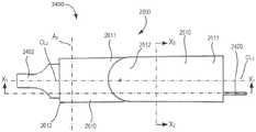
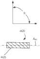
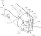
尽管上述的带(例如,带4420)被示出为沿带的纵向中心线具有恒定的横截面面积,但是在另一些实施例中,本文所示和所述的任何带可具有可变的截面面积、形状或尺寸。例如,在一些实施例中,器械可包括一个或多个带,所述一个或多个带在腕部内的区域(或该带被联接到末端执行器的区域)具有较小的横截面面积,而在轴内(或在致动器处)的区域具有较大的横截面面积。以这种方式,带的具有较大横截面面积的部分可以具有更大的强度,这进而可以使使用期间的带拉伸(变形)的量最小化。例如,图22是根据一个实施例的器械5400的一部分的示意图。器械5400包括腕部组件5500、带5420和工具构件5462。图23和图24是在正交于带5420的纵向中心线CL的平面内截取的带5420的截面图。器械5400被构造成使得带5420的运动产生腕部组件5500围绕俯仰轴线A1的运动、工具组件5462围绕偏航轴线A2的运动,或腕部组件5500的运动和工具组件5462的运动两者。Although the above-described belts (eg, belt 4420) are shown as having a constant cross-sectional area along the belt's longitudinal centerline, in other embodiments, any of the belts shown and described herein may have a variable cross-section area, shape or size. For example, in some embodiments, the instrument may include one or more straps having a smaller cross-sectional area in the region within the wrist (or where the strap is coupled to the end effector), Whereas the area within the shaft (or at the actuator) has a larger cross-sectional area. In this way, the portion of the belt with the larger cross-sectional area may have greater strength, which in turn may minimize the amount of belt stretching (deformation) during use. For example, Figure 22 is a schematic diagram of a portion of aninstrument 5400 according to one embodiment.Instrument 5400 includeswrist assembly 5500,strap 5420, andtool member 5462. 23 and 24 are cross-sectional views of thebelt 5420 taken in a plane orthogonal to the longitudinal centerline CL of thebelt 5420.Instrument 5400 is configured such that movement ofstrap 5420 produces movement ofwrist assembly 5500 about pitch axis A1, movementof tool assembly 5462 about yaw axis A2, orboth movement ofwrist assembly 5500 and movement oftool assembly 5462 .

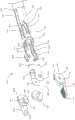
腕部组件5500(也称为接头组件)包括近侧的第一连杆5510和远侧的第二连杆5610。第一连杆5510具有联接到轴5410的近端部分5511。轴5410可以是将腕部组件5500联接到致动器5700的任何合适的细长轴。例如,在一些实施例中,轴5410可以是圆柱形轴,带5420和从致动器5700引出到腕部组件5500的其他部件(例如,电线、地线等)被布置在圆柱形轴中。近端部分5511可以经由任何合适的机构联接到轴5410。例如,在一些实施例中,近端部分5511可以匹配地设置在轴5410的一部分内(例如,通过过盈配合)。在一些实施例中,近端部分5511可以包括将近端部分5511联接到轴5410的一个或多个突起、凹部、开口或连接器。Wrist assembly 5500 (also referred to as a joint assembly) includes a proximalfirst link 5510 and a distalsecond link 5610. Thefirst link 5510 has a proximal end portion 5511 coupled to theshaft 5410.Shaft 5410 may be any suitable elongated shaft that coupleswrist assembly 5500 toactuator 5700. For example, in some embodiments, theshaft 5410 may be a cylindrical shaft in which thestrap 5420 and other components (eg, wires, ground wires, etc.) leading from theactuator 5700 to thewrist assembly 5500 are disposed. Proximal portion 5511 may be coupled toshaft 5410 via any suitable mechanism. For example, in some embodiments, proximal portion 5511 may be matingly disposed within a portion of shaft 5410 (eg, by an interference fit). In some embodiments, proximal portion 5511 can include one or more protrusions, recesses, openings, or connectors that couple proximal portion 5511 toshaft 5410.

第二连杆5610具有近端部分和远端部分5612。近端部分可旋转地联接到第一连杆5510以形成具有第一旋转轴线A1(其用作俯仰轴线,术语俯仰是任意的)的腕部组件5500,第二连杆5610相对于第一连杆围绕所述第一旋转轴线A1旋转。腕部组件5500能够包括任何合适的联接机构。例如,在一些实施例中,第二连杆5610能够经由本文示出和描述的类型的销接头联接到第一连杆5510。在另一些实施例中,第二连杆5610可经由本文所示和所述类型的配合盘表面联接到第一连杆5510。Thesecond link 5610 has a proximal portion and a distal portion 5612. The proximal portion is rotatably coupled to afirst link 5510 to form awrist assembly 5500 having a first axis of rotation A1 (which serves as a pitch axis, the term pitch is arbitrary), thesecond link 5610 is relative to the first The connecting rod rotates about thefirst rotation axis A1.Wrist assembly 5500 can include any suitable coupling mechanism. For example, in some embodiments, thesecond link 5610 can be coupled to thefirst link 5510 via a pin joint of the type shown and described herein. In other embodiments, thesecond link 5610 may be coupled to thefirst link 5510 via a mating disc surface of the type shown and described herein.

第二连杆5610的远端部分5612包括连接器5680,所述连接器5680被联接到工具构件5462的皮带轮部分5467,使得工具构件5462相对于腕部组件5500绕第二旋转轴线A2旋转。第二旋转轴线A2不平行于第一旋转轴线A1。轴线A2在工具构件一起旋转时用作偏航轴线(术语偏航是任意的),在工具构件相对于彼此相反地旋转时用作抓握轴线。因此,器械5400提供了多达三个自由度(即,围绕第一旋转轴线A1的俯仰运动、围绕第二旋转轴线A2的偏航旋转以及围绕第二旋转轴线A2的抓握运动)。连接器5680可以是任何合适的连接器以将工具构件5462可旋转地联接到腕部组件5500。例如,在一些实施例中,第二连杆5610可以包括U形夹和销,诸如在(于2008年7月16日提交)标题为“Medical Instrument ElectronicallyEnergized Using Drive Cables(使用驱动缆线电子激励的医疗器械)”的美国专利No.US9,204,923B2中示出和描述的销接头,该美国专利的全部内容通过引用整体并入本文。在另一些实施例中,第二连杆5610可以包括顺应机构,诸如在(2016年1月26日提交)标题为“Rolling-Contact Joint Mechanisms and Methods(滚动接触接头机构和方法)”的国际专利公开No.WO2016/123139A2中示出和描述的顺应机构,该国际专利公开的全部内容通过引用整体并入本文。The distal end portion 5612 of thesecond link 5610 includes aconnector 5680 that is coupled to thepulley portion 5467 of thetool member 5462 such that thetool member 5462 rotates relative to thewrist assembly 5500 about the second axis of rotation A2 . The second axis of rotation A2 is not parallel to the first axis of rotation A1 . Axis A2 serves as the yaw axis (the term yaw is arbitrary) when the tool members are rotated together and as the grip axis when the tool members are rotated opposite each other. Thus, theinstrument 5400 provides up to three degrees of freedom (ie, pitching motion about thefirst axis of rotation A1, yaw rotation about thesecond axis of rotation A2, and grasping motion about thesecond axis of rotation A2) .Connector 5680 may be any suitable connector to rotatablycouple tool member 5462 towrist assembly 5500. For example, in some embodiments, thesecond link 5610 may include a clevis and pin, such as described in (filed Jul. 16, 2008) entitled "Medical Instrument Electronically Energized Using Drive Cables. Medical Device)" US Patent No. US 9,204,923 B2, which is incorporated herein by reference in its entirety. In other embodiments, thesecond link 5610 may include a compliant mechanism, such as in the International Patent (filed January 26, 2016) entitled "Rolling-Contact Joint Mechanisms and Methods" The compliant mechanism shown and described in Publication No. WO2016/123139A2, the entire content of which is incorporated herein by reference in its entirety.

工具构件5462联接到腕部组件5500,并且包括接触部分5464和皮带轮部分5467。接触部分5464被构造成在外科手术过程中接合或操纵目标组织。例如,在一些实施例中,接触部分5464可以包括用作抓握器、切割器、组织操纵器等的接合表面。在另一些实施例中,接触部分5464可以是用于烧灼程序的通电工具构件。如上所述,皮带轮部分5467可旋转地联接到第二连杆5610,使得工具构件5462相对于腕部组件5500绕第二旋转轴线A2旋转,如箭头KK所示。以这种方式,工具构件5462的接触部分5464可以在外科手术过程中接合或操纵目标组织。工具构件5462(或本文描述的任何工具构件)可以是任何合适的医疗工具构件。而且,尽管仅示出了一个工具构件5462,但是在另一些实施例中,器械5400包括两个运动的工具构件,其协同执行抓握或剪切功能。以这种方式,工具构件5462可以形成用于器械5400的末端执行器的一部分。Tool member 5462 is coupled towrist assembly 5500 and includes acontact portion 5464 and apulley portion 5467 .Contact portion 5464 is configured to engage or manipulate target tissue during a surgical procedure. For example, in some embodiments, thecontact portion 5464 may include an engagement surface for use as a grasper, cutter, tissue manipulator, or the like. In other embodiments, thecontact portion 5464 may be an energized tool member for a cautery procedure. As described above, thepulley portion 5467 is rotatably coupled to thesecond link 5610 such that thetool member 5462 rotates relative to thewrist assembly 5500 about thesecond axis of rotation A2, as indicated by arrow KK. In this manner, the contactingportion 5464 of thetool member 5462 can engage or manipulate target tissue during a surgical procedure. Tool member 5462 (or any tool member described herein) can be any suitable medical tool member. Also, although only onetool member 5462 is shown, in other embodiments, theinstrument 5400 includes two moving tool members that cooperate to perform a grasping or cutting function. In this manner,tool member 5462 may form part of an end effector forinstrument 5400.

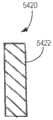
带5420(用作张力构件)限定纵向中心线CL,并且具有第一带部分5421、第二带部分5422、第三带部分5423、第四带部分5431和第五(最近侧)带部分5427。第一带部分5421设置在轴5410内,并且如图24所示,第一带部分5421在正交于纵向中心线CL的第一平面中具有第一横截面面积。第二带部分5422联接到工具构件5462。如图23所示,第二带部分5422在正交于纵向中心线CL的第二平面中具有第二横截面面积。具体地,第二横截面面积小于第一横截面面积。以此方式,带5420可在轴5410内具有较大(因此具有较高强度)的部分,并且在腕部组件2500(并且联接到工具构件5462)内具有较小的更柔性的部分。第三带部分5423在第二带部分5422和第一带部分5421之间,并且是较小的第二带部分5422和较大的第一带部分5421之间的过渡部分。尽管第三带部分5423被示出为在第一带部分5421与第二带部分5422之间关于纵向中心线CL对称地过渡,但是在另一些实施例中,第三带部分5423可以沿着纵向中心线CL不对称地过渡(或逐渐变细)。此外,尽管第三带部分5423被示出为在第一带部分5421和第二带部分5422之间连续且线性地过渡,但是在另一些实施例中,第三带部分5423可以沿纵向中心线CL不连续地或非线性地过渡(或逐渐变细)。Strap 5420 (serving as a tension member) defines a longitudinal centerline CL, and has afirst strap portion 5421 , asecond strap portion 5422 , athird strap portion 5423 , afourth strap portion 5431 , and a fifth (most proximal)strap portion 5427 . Thefirst strap portion 5421 is disposed within theshaft 5410, and as shown in FIG. 24, thefirst strap portion 5421 has a first cross-sectional area in a first plane orthogonal to the longitudinal centerline CL. Thesecond strap portion 5422 is coupled to thetool member 5462. As shown in FIG. 23, thesecond strap portion 5422 has a second cross-sectional area in a second plane orthogonal to the longitudinal centerline CL. Specifically, the second cross-sectional area is smaller than the first cross-sectional area. In this manner,strap 5420 may have a larger (and therefore higher strength) portion withinshaft 5410 and a smaller, more flexible portion within wrist assembly 2500 (and coupled to tool member 5462). Thethird strap portion 5423 is between thesecond strap portion 5422 and thefirst strap portion 5421 and is the transition portion between the smallersecond strap portion 5422 and the largerfirst strap portion 5421 . Although thethird strap portion 5423 is shown as transitioning between thefirst strap portion 5421 and thesecond strap portion 5422 symmetrically with respect to the longitudinal centerline CL, in other embodiments, thethird strap portion 5423 may be along the longitudinal direction The centerline CL transitions (or tapers) asymmetrically. Furthermore, although thethird strap portion 5423 is shown as transitioning continuously and linearly between thefirst strap portion 5421 and thesecond strap portion 5422, in other embodiments, thethird strap portion 5423 may be along the longitudinal centerline The CL transitions (or tapers) discontinuously or non-linearly.

如图所示,第二带部分5422被缠绕在工具构件5462的皮带轮部分5467周围。以这种方式,第四带部分5431延伸到轴5410中并且与第一带部分5421相对。在一些实施例中,带被整体地构造成使得第一带部分5421、第二带部分5422、第三带部分5423和第四带部分5431都在单个元件内。然而,在另一些实施例中,第四带部分5431可以与第一带部分5421分开地构造(或者可以是与第一带部分5421不同的元件)。第二带部分5422可以通过任何合适的机构联接到工具构件5462。例如,在一些实施例中,第二带部分5422可以通过与皮带轮部分5467的连接部分接合(或接收在其内)的销或突起而联接到工具构件5462。在另一些实施例中,第二带部分5422可以通过粘合剂被联接到皮带轮部分5467。As shown, thesecond belt portion 5422 is wrapped around thepulley portion 5467 of thetool member 5462. In this manner, thefourth strap portion 5431 extends into theshaft 5410 and is opposite thefirst strap portion 5421 . In some embodiments, the straps are integrally constructed such that thefirst strap portion 5421, thesecond strap portion 5422, thethird strap portion 5423, and thefourth strap portion 5431 are all within a single element. However, in other embodiments, thefourth strap portion 5431 may be constructed separately from the first strap portion 5421 (or may be a different element than the first strap portion 5421). Thesecond strap portion 5422 may be coupled to thetool member 5462 by any suitable mechanism. For example, in some embodiments, thesecond belt portion 5422 may be coupled to thetool member 5462 by a pin or protrusion that engages with (or is received within) a connecting portion of thepulley portion 5467 . In other embodiments, thesecond belt portion 5422 may be coupled to thepulley portion 5467 by adhesive.

第五(或最近侧)带部分5427联接到致动器5700。致动器可以是产生第五带部分5427的运动的马达驱动的致动器,如箭头KK所示。在第五带部分5427处的带移动产生工具构件5462的旋转(如箭头KK所示)、第二连杆5610的旋转或工具构件5462和第二连杆5610两者的旋转。通过增加第一带部分5421的横截面面积,带5420在轴5410内的刚度或刚性被增加,从而增加带5420在最近侧带部分5427和最远侧(或第二)带部分5422之间的运动守恒性。The fifth (or proximal-most)strap portion 5427 is coupled to theactuator 5700 . The actuator may be a motor-driven actuator that produces movement of thefifth belt portion 5427, as indicated by arrows KK. Belt movement atfifth belt portion 5427 produces rotation of tool member 5462 (as indicated by arrows KK), rotation ofsecond link 5610, or rotation of bothtool member 5462 andsecond link 5610. By increasing the cross-sectional area of thefirst strap portion 5421, the stiffness or rigidity of thestrap 5420 within theshaft 5410 is increased, thereby increasing the distance between theproximal-most strap portion 5427 and the distal-most (or second)strap portion 5422 of thestrap 5420. Conservation of motion.

如图所示,致动器5700可以包括相对于轴5410平移以移动第五带部分5427的线性致动器。然而,在另一些实施例中,致动器5700可以包括绞盘或旋转或“缠绕”第五带部分5427的其他马达驱动的滚子,以产生运动。例如,在一些实施例中,致动器5700能够包括在(于2008年7月16日提交)标题为“Medical Instrument Electronically Energized UsingDrive Cables(使用驱动缆线电子激励的医疗器械)”的美国专利No.US 9,204,923B2中示出和描述的任何后端组件或部件,该美国专利的全部内容通过引用整体并入本文。As shown, theactuator 5700 may include a linear actuator that translates relative to theaxis 5410 to move thefifth strap portion 5427. However, in other embodiments, theactuator 5700 may include a winch or other motor-driven roller that rotates or "winds" thefifth belt portion 5427 to generate motion. For example, in some embodiments, theactuator 5700 can be included in US Patent No. (filed July 16, 2008) entitled "Medical Instrument Electronically Energized Using Drive Cables" . Any backend assembly or component shown and described in US 9,204,923 B2, the entire contents of which are incorporated herein by reference in their entirety.

带5420(以及本文所述的任何带)可具有任何合适的形状。例如,在一些实施例中,第一带部分5421的形状可以是梯形的(见图24),而第二带部分5422的形状可以是矩形的。此外,带5420(以及本文所述的任何带)可以由任何合适的材料构造。例如,在一些实施例中,带5420(以及本文所述的任何带)可以由一系列(例如,通过粘合剂)粘合在一起的层压体构造而成。在另一些实施例中,可以通过任何其他合适的方法来接合层压体。层压体可以由任何合适的材料制成,所述材料包括钨、钢或任何合适的聚合物。Band 5420 (and any band described herein) can have any suitable shape. For example, in some embodiments, the shape of thefirst strap portion 5421 may be trapezoidal (see FIG. 24 ), while the shape of thesecond strap portion 5422 may be rectangular. Furthermore, the strap 5420 (and any strap described herein) may be constructed of any suitable material. For example, in some embodiments, tape 5420 (and any tape described herein) may be constructed from a series of laminates that are bonded together (eg, by adhesive). In other embodiments, the laminates may be joined by any other suitable method. The laminate can be made of any suitable material including tungsten, steel or any suitable polymer.

尽管上面示出的器械(例如器械4400和器械5400)包括单个工具构件,但是在另一些实施例中,器械可以包括任何合适数量的工具构件(例如以形成期望的末端执行器)。此外,尽管上述器械被示出为包括单个带并具有到工具构件(例如,器械2400)的单个连接点或者缠绕在工具构件(例如,器械5400)的皮带轮部分周围,但在另一些实施例中,器械可以包括任何合适数量的带以致动腕部组件和末端执行器。例如,图25是根据一个实施例的器械6400的一部分的示意图。器械6400包括腕部组件6500、第一带6420、第二带6440和末端执行器6460。器械6400被构造成使得第一带6420和第二带6440的各个部分的运动产生所述腕部组件6500绕俯仰轴线A1的运动、末端执行器6460绕偏航轴线A2的运动、末端执行器6460的抓握运动,或这些运动的任何组合。Although the instruments shown above (eg,instrument 4400 and instrument 5400) include a single tool member, in other embodiments, the instrument may include any suitable number of tool members (eg, to form a desired end effector). Additionally, while the above-described instruments are shown as including a single strap with a single connection point to a tool member (eg, instrument 2400 ) or wrapped around a pulley portion of a tool member (eg, instrument 5400 ), in other embodiments , the instrument may include any suitable number of straps to actuate the wrist assembly and end effector. For example, Figure 25 is a schematic diagram of a portion of aninstrument 6400 according to one embodiment.Instrument 6400 includeswrist assembly 6500 ,first strap 6420 ,second strap 6440 , andend effector 6460 .Instrument 6400 is configured such that movement of various portions offirst strap 6420 andsecondstrap 6440 produces movement ofwrist assembly 6500 about pitch axis A1, movementof end effector 6460 about yaw axis A2, end effector grasping motion of thedevice 6460, or any combination of these motions.

腕部组件6500包括近侧的第一连杆6510和远侧的第二连杆6610。第一连杆6510联接到本文示出和描述的类型的轴(未示出)。第二连杆6610具有近端部分和远端部分。近端部分可旋转地联接到第一连杆6510,以形成具有第一旋转轴线A1(其用作俯仰轴线,术语俯仰是任意的)的腕部组件6500,第二连杆6610相对于第一连杆6510绕第一旋转轴线A1旋转。腕部组件6500可包括任何合适的联接机构。例如,在一些实施例中,第二连杆6610可以经由本文示出和描述的类型的销接头联接到第一连杆6510。在另一些实施例中,第二连杆6610可以经由本文所示和所述类型的配合盘表面联接到第一连杆6510。Wrist assembly 6500 includes a proximalfirst link 6510 and a distal second link 6610. Thefirst link 6510 is coupled to a shaft (not shown) of the type shown and described herein. The second link 6610 has a proximal portion and a distal portion. The proximal portion is rotatably coupled to afirst link 6510 to form awrist assembly 6500 having a first axis of rotation A1 (which serves as a pitch axis, the term pitch is arbitrary), the second link 6610 is relative to thesecond link 6500. Alink 6510 rotates about thefirst rotation axis A1.Wrist assembly 6500 may include any suitable coupling mechanism. For example, in some embodiments, the second link 6610 may be coupled to thefirst link 6510 via a pin joint of the type shown and described herein. In other embodiments, the second link 6610 may be coupled to thefirst link 6510 via a mating disc surface of the type shown and described herein.

第二连杆6610的远端部分联接到末端执行器6460。更具体地,第二连杆6610的远端部分联接到第一工具构件6462的皮带轮部分6467和第二工具构件6482的皮带轮部分6487。该布置允许工具构件6462和工具构件6482中的每一个相对于腕部组件6500绕第二旋转轴线A2旋转。第二旋转轴线A2不平行于第一旋转轴线A1,并且在工具构件一起旋转时用作偏航轴线(术语偏航是任意的),并且在工具构件彼此相反地旋转时用作抓握轴线。因此,器械6400提供了多达三个自由度(即,围绕第一旋转轴线A1的俯仰运动、围绕第二旋转轴线A2的偏航旋转以及围绕第二旋转轴线A2的抓握运动)。尽管末端执行器6460被示为经由销连接器联接到第二连杆6610,但是在另一些实施例中,末端执行器6460可通过任何合适的机构联接到腕部组件6500。The distal portion of the second link 6610 is coupled to theend effector 6460 . More specifically, the distal end portion of the second link 6610 is coupled to thepulley portion 6467 of thefirst tool member 6462 and thepulley portion 6487 of thesecond tool member 6482 . This arrangement allows each oftool member 6462 andtool member 6482 to rotate relative towrist assembly 6500 about a second axis of rotation A2 . The second axis of rotation A2 is not parallel to the first axis of rotation A1 and serves as a yaw axis when the tool members are rotated together (the term yaw is arbitrary) and as a grip when the tool members are rotated against each other axis. Thus, theinstrument 6400 provides up to three degrees of freedom (ie, pitching motion about thefirst axis of rotation A1, yaw rotation about thesecond axis of rotation A2, and grasping motion about thesecond axis of rotation A2) . Althoughend effector 6460 is shown coupled to second link 6610 via a pin connector, in other embodiments,end effector 6460 may be coupled towrist assembly 6500 by any suitable mechanism.

末端执行器包括第一工具构件6462和第二工具构件6482。第一工具构件6462包括接触部分6464和皮带轮部分6467,并且第二工具构件6482包括接触部分6484和皮带轮部分6487。接触部分6464和接触部分6484均被构造成在外科手术过程中接合或操纵目标组织。例如,在一些实施例中,接触部分可以包括用作抓握器、切割器、组织操纵器等的接合表面。在另一些实施例中,接触部分可以是用于烧灼程序的通电工具构件。如上所述,皮带轮部分6467和皮带轮部分6487均可旋转地联接到第二连杆6610,使得工具构件6462相对于腕部组件6500绕第二旋转轴线A2旋转。皮带轮部分可以包括接触表面,相应的带(即,第一带6420和第二带6440)缠绕在该接触表面周围。第一工具构件6462和第二工具构件6482(或本文描述的任何工具构件)可以是任何合适的医疗工具构件。The end effector includes afirst tool member 6462 and asecond tool member 6482. Thefirst tool member 6462 includes acontact portion 6464 and apulley portion 6467 , and thesecond tool member 6482 includes acontact portion 6484 and apulley portion 6487 .Contact portion 6464 andcontact portion 6484 are each configured to engage or manipulate target tissue during a surgical procedure. For example, in some embodiments, the contact portion may include an engagement surface that functions as a grasper, cutter, tissue manipulator, or the like. In other embodiments, the contact portion may be an energized tool member for a cautery procedure. As described above, bothpulley portion 6467 andpulley portion 6487 are rotatably coupled to second link 6610 such thattool member 6462 rotates relative towrist assembly 6500 about second axis of rotation A2 . The pulley portion may include a contact surface around which the respective belts (ie, thefirst belt 6420 and the second belt 6440) are wound. Thefirst tool member 6462 and the second tool member 6482 (or any of the tool members described herein) can be any suitable medical tool members.

第一带6420(用作张力构件)具有第一近端部分6421、第二近端部分6431和远端部分6422。如图所示,远端部分6422缠绕在第一工具构件6462的皮带轮部分6467周围。这样,第一近端部分6421和第二近端部分6431均延伸穿过第一连杆6510并进入轴(未示出)。另外,第一近端部分6421和第二近端部分6431均被联接到致动器(未示出,但是类似于上述致动器5700),该致动器可以移动每个近端部分(如一系列标记为PITCH、YAW和GRIP的箭头所示)。第二带6440(还用作张力构件)具有第三近端部分6441、第四近端部分6451和远端部分6442。如图所示,远端部分6442被缠绕在第二工具构件6482的皮带轮部分6487周围。这样,第三近端部分6441和第四近端部分6451均延伸穿过第一连杆6510并进入轴(未示出)。另外,第三近端部分6441和第四近端部分6451均被联接到致动器(未示出,但是类似于上述致动器5700),该致动器可以移动每个近端部分(如一系列标记为PITCH、YAW和GRIP的箭头所示)。The first strap 6420 (which serves as the tension member) has a firstproximal portion 6421 , a secondproximal portion 6431 and adistal portion 6422 . As shown, thedistal end portion 6422 wraps around thepulley portion 6467 of thefirst tool member 6462. As such, both the firstproximal portion 6421 and the secondproximal portion 6431 extend through thefirst link 6510 and into the shaft (not shown). Additionally, both the firstproximal portion 6421 and the secondproximal portion 6431 are coupled to an actuator (not shown, but similar to theactuator 5700 described above) that can move each proximal portion (eg, a series labeled PITCH, YAW, and GRIP by arrows). The second strap 6440 (which also serves as a tension member) has a thirdproximal portion 6441 , a fourthproximal portion 6451 and adistal portion 6442 . As shown, thedistal portion 6442 is wrapped around thepulley portion 6487 of thesecond tool member 6482. As such, both the thirdproximal portion 6441 and the fourthproximal portion 6451 extend through thefirst link 6510 and into the shaft (not shown). Additionally, thirdproximal portion 6441 and fourthproximal portion 6451 are each coupled to an actuator (not shown, but similar to actuator 5700 described above) that can move each proximal portion (eg, a Series labeled PITCH, YAW, and GRIP are indicated by arrows).

在一些实施例中,第一带6420或第二带6440(或两者)可以被整体地构造成使得第一近端部分、第二近端部分和远端部分都在单个元件内。然而,在另一些实施例中,第一带6420或第二带6440(或两者)可包括多个分开构造的部件(例如,第一近端部分6421可与第二近端部分6431分开地构造)。而且,第一带6420或第二带6440(或两者)可具有如本文所述的任何合适的形状。在一些实施例中,第一带6420或第二带6440(或两者)可具有变化的横截面面积(如以上参照带5420所述)或可沿其纵向中心线扭转(如以上参照带4420所述)。在一些实施例中,第一带6420或第二带6440(或两者)可以由(例如,通过粘合剂)粘结在一起的一系列层压体构造而成。在另一些实施例中,可以通过任何其他合适的方法来接合层压体。层压体可以由任何合适的材料制成,所述材料包括钨、钢或任何合适的聚合物。In some embodiments, thefirst strap 6420 or the second strap 6440 (or both) may be integrally constructed such that the first proximal portion, the second proximal portion and the distal portion are all within a single element. However, in other embodiments, thefirst strap 6420 or the second strap 6440 (or both) may include multiple separately constructed components (eg, the firstproximal portion 6421 may be separate from the secondproximal portion 6431 structure). Also, thefirst strap 6420 or the second strap 6440 (or both) may have any suitable shape as described herein. In some embodiments, thefirst strap 6420 or the second strap 6440 (or both) may have a varying cross-sectional area (as described above with reference to strap 5420) or may be twisted along its longitudinal centerline (as described above with reference to strap 4420) said). In some embodiments, thefirst tape 6420 or the second tape 6440 (or both) may be constructed from a series of laminates that are bonded together (eg, by an adhesive). In other embodiments, the laminates may be joined by any other suitable method. The laminate can be made of any suitable material including tungsten, steel or any suitable polymer.

改变器械6400的俯仰、偏航或抓握通常需要分别施加到四个近端部分(第一近端部分6421、第二近端部分、第三近端部分6441和第四近端部分6451)中的每一个的运动或动作。带部分的运动通常可以一次或以任何期望的组合进行,以改变器械6400的俯仰、偏航和抓握。例如,俯仰轴线旋转使第二连杆6610绕第一旋转轴线A1(俯仰轴线)旋转,如箭头MM所示。为了绕俯仰轴线A1顺时针旋转,致动器(未示出)在释放(即,允许向远侧移动)相同长度的第三近端部分6441和第四近端部分6451的同时拉入(即,向近侧移动)相等长度的第一近端部分6421和第二近端部分6431。这由标记为PITCH的箭头示出。第一近端部分6421和第二近端部分6431在由引导通道通过腕部组件6500限定的力矩臂上向第二连杆6610施加力。类似地,第一连杆6510和第二连杆6610可以限定从俯仰轴线A1偏移的一个或多个引导通道,以产生围绕俯仰轴线A1的扭矩。引导通道可以是本文所述的任何引导通道(例如,结合腕部组件2500或腕部组件3500示出和描述的引导通道)。类似地,为了使第二连杆6610绕俯仰轴线A1逆时针旋转,致动器在释放(即,允许向远侧移动)相同长度的第一近端部分6421和第二近端部分6431的同时拉入(即,向近侧移动)相等长度的第三近端部分6441和第四近端部分6451。Altering the pitch, yaw or grip of theinstrument 6400 typically requires application to each of the four proximal sections (firstproximal section 6421, second proximal section, thirdproximal section 6441 and fourth proximal section 6451) of every movement or action. Movement of the belt portion can generally be done all at once or in any desired combination to alter the pitch, yaw and grip of theinstrument 6400. For example, rotation of the pitch axis rotates the second link 6610 about the first axis of rotation A1 (pitch axis), as indicated by arrow MM. To rotate clockwise about the pitch axis A1,an actuator (not shown) pulls in (ie, allows distal movement) while releasing (ie, allowing distal movement) of the third and fourthproximal portions 6441, 6451 of the same length. That is, moving proximally) firstproximal portion 6421 and secondproximal portion 6431 of equal length. This is shown by the arrow labeled PITCH. The firstproximal portion 6421 and the secondproximal portion 6431 apply a force to the second link 6610 on the moment arm defined by the guide channel through thewrist assembly 6500. Similarly,first link 6510 and second link 6610 may define one or more guide channels offset from pitch axis A1 to generate torque about pitch axis A1 . The guide channel may be any of the guide channels described herein (eg, those shown and described in connection withwrist assembly 2500 or wrist assembly 3500). Similarly, in order to rotate the second link 6610 counterclockwise about the pitch axis A1 , the actuator releases (ie, allows distal movement) of the firstproximal portion 6421 and the secondproximal portion 6431 of the same length when the The thirdproximal portion 6441 and the fourthproximal portion 6451 of equal length are simultaneously pulled in (ie, moved proximally).

偏航旋转是第一工具构件6462和第二工具构件6482绕第二旋转轴线A2(偏航轴线)沿相同方向和通过相同角度的旋转。特别地,当致动器拉入(即,向近侧移动)一定长度的第一近端部分6421和释放(即,允许向远侧移动)相等长度的第二近端部分6431时,第一工具构件6462将绕偏航轴线A2沿顺时针方向旋转(参照箭头NN)。为了该旋转,皮带轮部分6467的引导通道或皮带轮表面限定力矩臂,通过第一带6420传递的力施加在该力矩臂。所产生的扭矩使第一工具构件6462顺时针旋转。在该运动期间,第一近端部分6421和第二近端部分6431均在第二连杆6610的引导通道内滑动。如果同时,致动器拉入一定长度的第四近端部分6451并释放相同长度的第三近端部分6441,第二工具构件6482将顺时针旋转通过与第一工具构件6462旋转通过的角度相同的角度。因此,第一工具构件6462和第二工具构件6482保持它们相对于彼此的位置,并且作为一个单元旋转通过一偏航角。当致动器在释放相同长度的第一近端部分6421和第四近端部分6451的同时拉入相等长度的第二近端部分6431和第三近端部分6441时,类似地实现末端执行器6460的逆时针旋转。这由标记为YAW的箭头图示。A yaw rotation is a rotation of thefirst tool member 6462 and thesecond tool member 6482 in the same direction and through the same angle about asecond rotational axis A2 (yaw axis). In particular, when the actuator draws in (ie, moves proximally) a firstproximal portion 6421 of a certain length and releases (ie, allows moving distally) an equal length secondproximal portion 6431, the first Thetool member 6462 will rotate in a clockwise direction about the yaw axis A2( see arrow NN). For this rotation, the guide channel or pulley surface of thepulley portion 6467 defines a moment arm on which the force transmitted through thefirst belt 6420 is applied. The resulting torque rotates thefirst tool member 6462 clockwise. During this movement, both the firstproximal end portion 6421 and the secondproximal end portion 6431 slide within the guide channel of the second link 6610 . If, at the same time, the actuator pulls in a length of fourthproximal portion 6451 and releases a thirdproximal portion 6441 of the same length, thesecond tool member 6482 will rotate clockwise through the same angle as thefirst tool member 6462 rotates Angle. Thus, thefirst tool member 6462 and thesecond tool member 6482 maintain their position relative to each other and rotate through a yaw angle as a unit. The end effector is similarly implemented when the actuator pulls in the secondproximal portion 6431 and the thirdproximal portion 6441 of equal length while releasing the firstproximal portion 6421 and the fourthproximal portion 6451 of thesame length 6460 counterclockwise rotation. This is illustrated by the arrow labeled YAW.

抓握旋转是第一工具构件6462和第二工具构件6482绕偏航轴线A2沿相反方向和通过相同角度的旋转。为了开启末端执行器6460的抓握,致动器在释放相同长度的第二近端部分6431和第四近端部分6451的同时拉入相等长度的第一近端部分6421和第三近端部分6441。这使得第一工具构件6562与第二工具构件6482沿相反的方向旋转。为了闭合末端执行器的抓握,致动器在释放相同长度的第一近端部分6421和第三近端部分6441的同时拉入相等长度的第二近端部分6431和第四近端部分6451。这使得第一工具构件6562朝第二工具构件6482旋转。当工具构件的接触部分接触时,第二近端部分6431和第四近端部分6451中的张力可以保持大于第一近端部分6421和第三近端部分6441中的张力,以保持期望的夹持力。A grip rotation is a rotation of thefirst tool member 6462 and thesecondtool member 6482 about the yaw axis A2 in opposite directions and through the same angle. To initiate grasping ofend effector 6460, the actuator pulls in firstproximal portion 6421 and third proximal portion of equal length while releasing secondproximal portion 6431 and fourthproximal portion 6451 ofequal length 6441. This causes the first tool member 6562 and thesecond tool member 6482 to rotate in opposite directions. To close the grip of the end effector, the actuator pulls in the secondproximal portion 6431 and the fourthproximal portion 6451 of equal length while releasing the firstproximal portion 6421 and the thirdproximal portion 6441 of the same length . This causes the first tool member 6562 to rotate towards thesecond tool member 6482. When the contacting portions of the tool members are in contact, the tension in the secondproximal portion 6431 and the fourthproximal portion 6451 can be maintained greater than the tension in the firstproximal portion 6421 and the thirdproximal portion 6441 to maintain the desired grip hold.

图26-36是根据一个实施例的器械7400的各种视图。在一些实施例中,器械7400或其中的任何部件可选地是执行外科手术程序的手术系统的部分,并且其可以包括操纵器单元、一系列运动联动装置、一系列插管等。器械7400(和本文描述的任何器械)可以用在任何合适的手术系统中,诸如以上示出和描述的MIRS系统1000。器械7400包括致动器组件7700、轴7410、腕部组件7500和末端执行器7460。参照图29,器械7400还包括将后端机构7700联接到腕部组件7500的一系列带(具体地,第一带7420、第二带7430、第三带7440和第四带7450)。器械7400被构造成使得带的运动产生腕部组件7500围绕第一旋转轴线A1(参照图27,其用作俯仰轴线,术语俯仰是任意的)的旋转(即,俯仰旋转)、末端执行器7460围绕第二旋转轴线A2(参照图27和图28,用作偏航轴线)的偏航旋转、末端执行器7460的工具构件围绕第二旋转轴线A2的夹持旋转或这些运动的任何组合。可以通过以与上文针对器械6400所述的类似的方式操纵四个带来执行改变器械7400的俯仰、偏航或抓握。因此,四个带中的每一个的具体移动来实现期望的运动未在下面描述。26-36 are various views of aninstrument 7400 according to one embodiment. In some embodiments,instrument 7400, or any components therein, is optionally part of a surgical system that performs a surgical procedure, and it may include a manipulator unit, a series of motion linkages, a series of cannulas, and the like. Instrument 7400 (and any instrument described herein) may be used in any suitable surgical system, such asMIRS system 1000 shown and described above.Instrument 7400 includesactuator assembly 7700,shaft 7410,wrist assembly 7500, andend effector 7460. 29, theinstrument 7400 also includes a series of straps (specifically, afirst strap 7420, asecond strap 7430, athird strap 7440, and a fourth strap 7450) that couple therear end mechanism 7700 to thewrist assembly 7500.Instrument 7400 is configured such that movement of the strap produces rotation (ie, pitch rotation) ofwrist assembly 7500 about a first axis of rotation A1 (refer to FIG. 27 , which serves as a pitch axis, term pitch is arbitrary), end effector Yaw rotation of the 7460 about thesecond axis of rotation A2 (referring to Figures 27 and 28, serving as the yaw axis), clamping rotation of the tool member of theend effector 7460 about thesecond axis of rotation A2, or any of these movements. combination. Changing the pitch, yaw, or grip ofinstrument 7400 can be performed by manipulating the four straps in a similar manner as described above forinstrument 6400. Therefore, the specific movement of each of the four belts to achieve the desired motion is not described below.

后端机构7700产生第一带7420、第二带7430、第三带7440和第四带7450中的每一个的运动,以在腕部组件7500处产生期望的运动(俯仰、偏航或抓握)。具体地,后端机构7700包括在近侧方向上移动一些带(即,拉入某些带),同时允许其他带的向远侧运动(即,释放或“付出(paying out)”)相等长度的部件和控件。以这种方式,后端机构7700可以在带内保持期望的张力,并且在一些实施例中,可以确保在腕部组件7500的整个运动范围期间带的长度被保持不变(即,以相等量移动)。然而,在另一些实施例中,不需要保持带的长度不变。Therear end mechanism 7700 produces movement of each of thefirst strap 7420, thesecond strap 7430, thethird strap 7440, and thefourth strap 7450 to create the desired motion (pitch, yaw, or grip) at the wrist assembly 7500 ). Specifically, therear end mechanism 7700 includes moving some straps in a proximal direction (ie, pulling some straps in) while allowing for distal movement (ie, releasing or "paying out") of other straps an equal length components and controls. In this manner, therear end mechanism 7700 can maintain a desired tension within the strap and, in some embodiments, can ensure that the length of the strap is maintained (ie, in equal amounts) during the entire range of motion of thewrist assembly 7500. move). However, in other embodiments, the length of the strap need not be kept constant.

在一些实施例中,后端机构7700可以包括一个或多个线性致动器,其产生带的一部分的平移(线性运动)。这样的后端机构可以包括例如万向架(gimbal)、杠杆或任何其他合适的机构以直接拉动(或释放)任何带的端部。例如,在一些实施例中,后端机构7700可以包括在(于2014年8月15日提交)标题为“Lever Actuated Gimbal Plate(杠杆致动的万向板)”的美国专利申请公布No.US20157/0047454A1,或(于2001年6月28日提交)标题为“Surgical Tool Having Positively Positionable Tendon-Actuated Multi-DiskWrist Joint(具有可积极定位的肌腱致动多盘腕部接头的手术工具)”的美国专利No.US6,817,974B2”中描述的任何后端组件或部件,上述美国专利申请和美国专利的全部内容通过引用整体并入本文。然而,在另一些实施例中,后端结构7700可以包括绞盘或旋转或“缠绕”任何带的一部分的其他马达驱动的滚子,以产生期望的带运动。例如,在一些实施例中,后端机构7700能够包括在(于2008年7月16日提交)标题为“Medical InstrumentElectronically Energized Using Drive Cables(使用驱动缆线电子激励的医疗器械)”的美国专利No.US 9,204,923B2中描述的任何后端组件或部件,该美国专利的全部内容通过引用整体并入本文。In some embodiments, therear end mechanism 7700 may include one or more linear actuators that produce translation (linear motion) of a portion of the belt. Such a rear end mechanism may include, for example, a gimbal, a lever, or any other suitable mechanism to directly pull (or release) the end of any strap. For example, in some embodiments,back end mechanism 7700 may be included in US Patent Application Publication No. US20157 (filed August 15, 2014) entitled "Lever Actuated Gimbal Plate" /0047454A1, or (filed June 28, 2001) U.S. entitled "Surgical Tool Having Positively Positionable Tendon-Actuated Multi-DiskWrist Joint" Any of the backend assemblies or components described in Patent No. US 6,817,974B2", the entire contents of the aforementioned US Patent Application and US Patents are hereby incorporated by reference in their entirety. However, in other embodiments, thebackend structure 7700 may include A winch or other motor-driven roller that rotates or "winds" a portion of any belt to create the desired belt motion. For example, in some embodiments, theback end mechanism 7700 can be included in (filed Jul 16, 2008 ) any of the backend assemblies or components described in U.S. Patent No. US 9,204,923 B2, entitled "Medical Instrument Electronically Energized Using Drive Cables," the entire contents of which are incorporated by reference in their entirety. into this article.

轴7410可以是将腕部组件7500联接至后端机构7700的任何合适的细长轴。具体地,轴7410包括联接至后端机构7700的壳体的近端部分7411和联接到腕部组件7500的远端部分7412。轴7410限定一条通路或一系列通路,带和其他部件(例如电线、地线等)可以通过这些通路从后端机构7700引出到腕部组件7500。尽管被示出为圆柱形,但是在另一些实施例中,轴7410可具有任何合适的形状。Shaft 7410 may be any suitable elongated shaft that coupleswrist assembly 7500 torear end mechanism 7700. Specifically,shaft 7410 includes aproximal portion 7411 coupled to the housing ofrear end mechanism 7700 and adistal portion 7412 coupled towrist assembly 7500. Theshaft 7410 defines a passage or series of passages through which straps and other components (eg, wires, ground wires, etc.) can be routed from theback end mechanism 7700 to thewrist assembly 7500. Although shown as cylindrical, in other embodiments, theshaft 7410 may have any suitable shape.

参照图27和图28,腕部组件7500包括近侧的第一连杆7510和远侧的第二连杆7610。第一连杆7510具有近端部分7511和远端部分7512。近端部分7511联接至轴7410的远端部分7412。近端部分7511可通过任何合适的机构联接至轴7410。例如,在一些实施例中,近端部分7511可以配合地设置在轴的一部分内(例如,通过过盈配合)。如图所示,近端部分7511可包括将近端部分7511联接到轴的一个或多个突起、凹部、开口或连接器。近端部分7511可以通过粘合剂、焊接或任何其他永久性联接机构(即,在正常使用期间不打算被移除的联接机构)固定地联接至轴7410。27 and 28, thewrist assembly 7500 includes a proximalfirst link 7510 and a distalsecond link 7610. Thefirst link 7510 has aproximal portion 7511 and adistal portion 7512. Theproximal portion 7511 is coupled to thedistal portion 7412 of theshaft 7410.Proximal portion 7511 may be coupled toshaft 7410 by any suitable mechanism. For example, in some embodiments,proximal portion 7511 may be matingly disposed within a portion of the shaft (eg, by an interference fit). As shown, theproximal portion 7511 can include one or more protrusions, recesses, openings, or connectors that couple theproximal portion 7511 to the shaft.Proximal portion 7511 may be fixedly coupled toshaft 7410 by adhesive, welding, or any other permanent coupling mechanism (ie, a coupling mechanism that is not intended to be removed during normal use).

远端部分7512包括接头部分7540,接头部分7540可旋转地联接到第二连杆7610的配合接头部分7640。以这样的方式,第一连杆7510和第二连杆7610形成腕部组件7500,腕部组件7500具有第二连杆7610相对于第一连杆7510围绕其旋转的第一旋转轴线A1(用作俯仰轴线,术语俯仰是任意的)。具体地,接头部分7540包括被凹部间隔开的一系列的齿7544。由于腕部接头不是销接头,因此俯仰轴线A1将在第二连杆7610旋转时相对于第一连杆7510移动。一系列的齿7544和凹部可类似于在(于2015年2月20日提交)标题为“Mechanical WristJoints with Enhanced Range of Motion,and Related Devices and Methods(具有增强的运动范围的机械腕部接头以及相关设备和方法)”的美国专利申请公布No.US 2017/0120457A1中示出和描述的那些,该美国专利申请公布的全部内容通过引用整体并入本文。Thedistal end portion 7512 includes ajoint portion 7540 that is rotatably coupled to a matingjoint portion 7640 of thesecond link 7610. In this manner, thefirst link 7510 and thesecond link 7610 form awrist assembly 7500 having a first axis of rotation A1 ( Used as a pitch axis, the term pitch is arbitrary). Specifically, thejoint portion 7540 includes a series ofteeth 7544 that are spaced apart by recesses. Since the wrist joint is not a pin joint, the pitch axis A1 will move relative to thefirstlink 7510 as thesecond link 7610 rotates. A series ofteeth 7544 and recesses may be similar to those described in (submitted on February 20, 2015) entitled "Mechanical WristJoints with Enhanced Range of Motion, and Related Devices and Methods. those shown and described in US Patent Application Publication No. US 2017/0120457 A1, which is hereby incorporated by reference in its entirety.

参照图30和图31,在第一连杆7510中限定第一引导通道7515、第二引导通道7525和中心孔7535。例如,中心孔7535可以包含腕部组件的各种部件,诸如电线,(或允许腕部组件的各种部件通过)。第一连杆7510包括均形成第一引导通道7515的边界的一部分的内部引导表面7516和外部引导表面7517;以及均形成第二引导通道7525的边界的一部分的内部引导表面7526和外部引导表面7527。第一带7420和第二带7430可移动地设置在第一引导通道7515内。第三带7440和第四带7450可移动地设置在第二引导通道7525内。因此,第一引导通道7515和第二引导通道7525中的每个包含两个带。Referring to FIGS. 30 and 31 , afirst guide channel 7515 , asecond guide channel 7525 and acentral hole 7535 are defined in thefirst link 7510 . For example, thecentral hole 7535 may contain various components of the wrist assembly, such as wires, (or allow passage of various components of the wrist assembly).First link 7510 includesinner guide surface 7516 andouter guide surface 7517 each forming part of the boundary offirst guide channel 7515; andinner guide surface 7526 andouter guide surface 7527 each forming part of the boundary ofsecond guide channel 7525 . Thefirst strap 7420 and thesecond strap 7430 are movably disposed within thefirst guide channel 7515. Thethird strap 7440 and thefourth strap 7450 are movably disposed within thesecond guide channel 7525 . Thus, each of thefirst guide channel 7515 and thesecond guide channel 7525 contains two bands.

如图28所示,第一连杆7510和第二连杆7610限定纵向中心线CL,在器械处于初始(或“笔直”构造)时该纵向中心线CL与俯仰轴线A1相交。如上所述,当第二连杆7610绕俯仰轴线A1旋转时,接头部分7540和接头部分7640之间的滚动界面使得俯仰轴线A1将略微移动并且不再与纵向中心线CL对准。如图30和图31所示,内部引导表面7516的至少一部分和外部引导表面7517的至少一部分沿着纵向中心线CL弯曲。类似地,内部引导表面7526的至少一部分和外部引导表面7527的至少一部分沿着纵向中心线CL弯曲。内部引导表面7516、7526和外部引导表面7517、7527可以限定任何合适的曲率半径,并且可以具有不同的弯曲形状,类似于上文关于器械3400所描述的形状。以这种方式,当第二连杆7610相对于第一连杆7510绕俯仰轴线A1旋转(参照图27中的箭头OO)时,第一带7420可以接触内部引导表面7516和外部引导表面7517的弯曲部分以在器械7400的致动期间保持期望的弯曲几何形状、带张力等。类似地,当第二连杆7610相对于第一连杆7510绕俯仰轴线A1旋转时,第二带7440可以接触内部引导表面7526和外部引导表面7527的弯曲部分以在器械7400的致动期间保持期望的弯曲几何形状、带张力等。As shown in Figure 28, thefirst link 7510 and thesecond link 7610 definea longitudinal centerline CL that intersects the pitch axis A1 when the instrument is in the initial (or "straight" configuration). As described above, when thesecond link 7610 is rotatedabout the pitch axis A1, the roll interface between thejoint portion 7540 and the joint portion7640 is such that the pitch axis A1 will move slightly and no longer align with the longitudinal centerline CL. As shown in FIGS. 30 and 31 , at least a portion of theinner guide surface 7516 and at least a portion of theouter guide surface 7517 are curved along the longitudinal centerline CL. Similarly, at least a portion ofinner guide surface 7526 and at least a portion ofouter guide surface 7527 are curved along longitudinal centerline CL. Theinner guide surfaces 7516, 7526 and theouter guide surfaces 7517, 7527 may define any suitable radius of curvature and may have various curved shapes, similar to the shapes described above with respect to theinstrument 3400. In this manner, thefirst strap 7420 may contact theinner guide surface 7516 and theouter guide surface 7517 as thesecond link 7610 rotates relative to thefirstlink 7510 about the pitch axis A1 (refer to arrow OO in FIG. 27 ) to maintain the desired bend geometry, strap tension, etc. during actuation of theinstrument 7400. Similarly, assecond link 7610 rotates relative tofirst link 7510 about pitch axis A1 ,second strap 7440 may contact the curved portions ofinner guide surface 7526 andouter guide surface 7527 for during actuation ofinstrument 7400 Maintain desired bend geometry, belt tension, etc.

尽管第一引导通道7515和第二引导通道7525沿着纵向中心线CL弯曲,但是内部引导表面7516、7526和外部引导表面7517、7527中的每个在正交于纵向中心线CL的横截平面内截取的一部分是线性的。如上面参照器械3400的致动所述,当第二连杆7610相对于第一连杆7510旋转时,这种布置允许内部引导表面7516和外部引导表面7517沿线性横截面接触表面(而不是仅在横截面中的单个点处)分别接触第一带7420和第二带7430的对应的内部接触表面和外部接触表面。当第二连杆7610相对于第一连杆7510旋转时,这种布置还允许内部引导表面7526和外部引导表面7527沿线性横截面接触表面分别接触第三带7440和第四带7450的对应的内部接触表面和外部接触表面。While thefirst guide channel 7515 and thesecond guide channel 7525 are curved along the longitudinal centerline CL, each of theinner guide surfaces 7516, 7526 and theouter guide surfaces 7517, 7527 are in a cross-sectional plane orthogonal to the longitudinal centerline CL A portion of the inner truncation is linear. As described above with reference to actuation ofinstrument 3400, this arrangement allowsinner guide surface 7516 andouter guide surface 7517 to contact surfaces along a linear cross-section assecond link 7610 rotates relative to first link 7510 (rather than only At a single point in the cross-section) contact the corresponding inner and outer contact surfaces of the first andsecond bands 7420 and 7430, respectively. This arrangement also allows theinner guide surface 7526 and theouter guide surface 7527 to contact corresponding ones of the third andfourth straps 7440 and 7450, respectively, along the linear cross-sectional contact surfaces when thesecond link 7610 is rotated relative to thefirst link 7510. Internal contact surface and external contact surface.

第一引导通道7515(以及因此其中的第一带7420和第二带7430的部分)从纵向中心线CL和第一旋转轴线A1偏移。以这种方式,经由第一带7420或第二带7430在第二连杆7610上施加力产生围绕第一旋转轴线A1的扭矩。这可以导致第二连杆7610相对于第一连杆7510旋转,如图27中的箭头OO所示。第二引导通道7525(以及因此其中的第三带7440和第四带7450的部分)从纵向中心线CL和第一旋转轴线A1偏移。以这种方式,经由第三带7440或第四带7450在第二连杆7610上施加力产生围绕第一旋转轴线A1的扭矩。这可以导致第二连杆7610相对于第一连杆7510旋转,如图27中的箭头OO所示。The first guide channel 7515 (and thus the portion of the first andsecond straps 7420 and 7430 therein) is offset from the longitudinal centerline CL and thefirst axis of rotation A1. In this manner, the application of a force on thesecond link 7610 via thefirst belt 7420 or thesecond belt 7430 produces a torque about the first axis of rotation A1 . This can cause thesecond link 7610 to rotate relative to thefirst link 7510 as indicated by arrow OO in FIG. 27 . The second guide channel 7525 (and thus the portions of the third andfourth bands 7440 and 7450 therein) are offset from the longitudinal centerline CL and thefirst axis of rotation A1. In this manner, the application of a force on thesecond link 7610 via thethird belt 7440 or thefourth belt 7450 produces a torque about thefirst axis of rotation A1. This can cause thesecond link 7610 to rotate relative to thefirst link 7510 as indicated by arrow OO in FIG. 27 .

第二连杆7610具有近端部分7611和远端部分7612。如上所述,近端部分7611包括可旋转地联接至第一连杆7510的接头部分7540的接头部分7640。具体地,接头部分7640包括被凹部间隔开的一系列的齿7644。一系列的齿7644与第一连杆7510的一系列的齿7544(或销)相互啮合。一系列的齿7644和凹部可以类似于在(于2015年2月20日提交)标题为“Mechanical Wrist Joints with Enhanced Range of Motion,and Related Devicesand Methods(具有增强的运动范围的机械腕部接头以及相关设备和方法)”的美国专利申请公布No.US 2017/0120457A1中示出和描述的那些,该美国专利申请公布的全部内容通过引用整体并入本文。Thesecond link 7610 has aproximal portion 7611 and adistal portion 7612. As discussed above,proximal portion 7611 includesjoint portion 7640 that is rotatably coupled tojoint portion 7540 offirst link 7510. Specifically,joint portion 7640 includes a series ofteeth 7644 that are spaced apart by recesses. A series ofteeth 7644 intermesh with a series of teeth 7544 (or pins) of thefirst link 7510. A series ofteeth 7644 and recesses may be similar to those described in (submitted on February 20, 2015) entitled "Mechanical Wrist Joints with Enhanced Range of Motion, and Related Devices and Methods. those shown and described in US Patent Application Publication No. US 2017/0120457 A1, which is hereby incorporated by reference in its entirety.

第二连杆7610的远端部分7612包括连接器7680,该连接器7680被联接到末端执行器7460。以此方式,第一工具构件7462和第二工具构件7482相对于第二连杆7610绕第二旋转轴线A2旋转。连接器7680是销型连接器,并且包括由销开口7682支撑的销7683(并且销被放置在销开口内)。在一些实施例中,连接器7680可以包括在(于2008年7月16日提交)标题为“Medical Instrument Electronically Energized Using Drive Cables(使用驱动缆线电子激励的医疗器械)”的美国专利No.US 9,204,923B2中示出和描述的销接头的任何结构和特征,该美国专利的全部内容通过引用整体并入本文。如图27所示,第二旋转轴线A2不平行于俯仰轴线A1。因此,器械7400提供了多达三个自由度(即,围绕第一旋转轴线A1的俯仰运动、围绕第二旋转轴线A2的偏航旋转以及围绕第二旋转轴线A2的抓握运动)。例如,图36示出了与图27所示相比,末端执行器7460被转变到第二偏航构造。Thedistal portion 7612 of thesecond link 7610 includes aconnector 7680 that is coupled to theend effector 7460. In this manner, thefirst tool member 7462 and thesecond tool member 7482 rotate relative to thesecond link 7610 about the second axis of rotation A2 .Connector 7680 is a pin-type connector and includespins 7683 supported by pin openings 7682 (and the pins are placed within the pin openings). In some embodiments, theconnector 7680 may be included in US Patent No. US (filed July 16, 2008) entitled "Medical Instrument Electronically Energized Using Drive Cables" Any structures and features of the pin joint shown and described in 9,204,923 B2, the entire contents of which are incorporated herein by reference in their entirety. As shown in Figure27 , thesecond rotation axis A2 is not parallel to the pitch axis A1. Thus, theinstrument 7400 provides up to three degrees of freedom (ie, pitching motion about thefirst axis of rotation A1, yaw rotation about thesecond axis of rotation A2, and grasping motion about thesecond axis of rotation A2) . For example, FIG. 36 shows theend effector 7460 being transitioned to a second yaw configuration compared to that shown in FIG. 27 .

参照图32和图33,在第二连杆7610中限定第一引导通道7615、第二引导通道7625和中心孔7635。中心孔7635与中心孔7535对准,并且可以容纳腕部组件的各种部件,诸如例如电线,(或允许腕部组件的各种部件通过)。以这种方式,来自后端组件7700的电流可以经由穿过中心孔7535、7635的部件被供应到末端执行器7460。第二连杆7610包括均形成第一引导通道7615的边界的一部分的内部引导表面7616和外部引导表面7617;以及均形成第二引导通道7625的边界的一部分的内部引导表面7626和外部引导表面7627。第一引导通道7615与(第一连杆7510的)第一引导通道7515对准,并且第二引导通道7625与(第一连杆7510的)第二引导通道7525对准。以这种方式,第一带7420和第二带7430能够从轴7410引出并且穿过第一引导通道7515和第一引导通道7615以联接到第一工具构件7462。第三带7440和第四带7450能够从轴7410引出并且穿过第二引导通道7525和第二引导通道7625以联接到第二工具构件7482。Referring to FIGS. 32 and 33 , afirst guide channel 7615 , asecond guide channel 7625 and acentral hole 7635 are defined in thesecond link 7610 . Thecentral hole 7635 is aligned with thecentral hole 7535 and can accommodate (or allow passage of) various components of the wrist assembly, such as, for example, wires. In this manner, electrical current from therear end assembly 7700 may be supplied to theend effector 7460 via components passing through thecentral holes 7535, 7635.Second link 7610 includesinner guide surface 7616 andouter guide surface 7617 each forming part of the boundary offirst guide channel 7615; andinner guide surface 7626 andouter guide surface 7627 each forming part of the boundary ofsecond guide channel 7625 . Thefirst guide channel 7615 is aligned with the first guide channel 7515 (of the first link 7510), and thesecond guide channel 7625 is aligned with the second guide channel 7525 (of the first link 7510). In this manner, thefirst strap 7420 and thesecond strap 7430 can be led out of theshaft 7410 and through thefirst guide channel 7515 and thefirst guide channel 7615 to couple to thefirst tool member 7462 . Thethird strap 7440 and thefourth strap 7450 can be led out from theshaft 7410 and through thesecond guide channel 7525 and thesecond guide channel 7625 to couple to thesecond tool member 7482 .

如图32和图33所示,内部引导表面7616的至少一部分和外部引导表面7617的至少一部分沿着纵向中心线CL弯曲。类似地,内部引导表面7626的至少一部分和外部引导表面7627的至少一部分沿着纵向中心线CL弯曲。内部引导表面7616、7626和外部引导表面7617、7627可以限定任何合适的曲率半径,并且可以具有不同的弯曲形状,类似于上文关于器械3400所描述的形状。当第二连杆7610相对于第一连杆7510绕俯仰轴线A1旋转时(参照图27中的箭头OO),第一带7420可以接触内部引导表面7616和外部引导表面7617的弯曲部分以在器械7400的致动期间保持期望的弯曲几何形状、带张力等。类似地,当第二连杆7610相对于第一连杆7510绕俯仰轴线A1旋转时,第二带7440可以接触内部引导表面7626和外部引导表面7627的弯曲部分以在器械7400的致动期间保持期望的弯曲几何形状、带张力等。As shown in FIGS. 32 and 33 , at least a portion of theinner guide surface 7616 and at least a portion of theouter guide surface 7617 are curved along the longitudinal centerline CL. Similarly, at least a portion ofinner guide surface 7626 and at least a portion ofouter guide surface 7627 are curved along longitudinal centerline CL. Theinner guide surfaces 7616, 7626 and theouter guide surfaces 7617, 7627 may define any suitable radius of curvature and may have different curved shapes, similar to the shapes described above with respect to theinstrument 3400. When thesecond link 7610 is rotated about the pitch axis A1 relative to thefirst link 7510 (refer to arrow OO in FIG. 27 ), thefirst strap 7420 may contact the curved portions of theinner guide surface 7616 and theouter guide surface 7617 to The desired bend geometry, strap tension, etc. are maintained during actuation of theinstrument 7400. Similarly, assecond link 7610 rotates relative tofirst link 7510 about pitch axis A1 ,second strap 7440 may contact the curved portions ofinner guide surface 7626 andouter guide surface 7627 for during actuation ofinstrument 7400 Maintain desired bend geometry, belt tension, etc.

尽管第一引导通道7615和第二引导通道7625沿纵向中心线CL弯曲,但是内部引导表面7616、7626和外部引导表面7617、7627中的每个在正交于纵向中心线CL的横截平面内截取的一部分是线性的。如上面参照器械3400的致动所述,当第二连杆7610相对于第一连杆7510旋转时,该布置允许内部引导表面7616和外部引导表面7617沿线性横截面接触表面(而不是仅在横截面中的单个点处)分别接触第一带7420和第二带7430的对应的内部接触表面和外部接触表面。当第二连杆7610相对于第一连杆7510旋转时,这种布置还允许内部引导表面7626和外部引导表面7627沿线性横截面接触表面分别接触第三带7440和第四带7450的对应的内部接触表面和外部接触表面。Although thefirst guide channel 7615 and thesecond guide channel 7625 are curved along the longitudinal centerline CL, each of theinner guide surfaces 7616, 7626 and theouter guide surfaces 7617, 7627 are in a cross-sectional plane normal to the longitudinal centerline CL The truncated part is linear. As described above with reference to actuation ofinstrument 3400, this arrangement allowsinner guide surface 7616 andouter guide surface 7617 to contact surfaces along a linear cross-section whensecond link 7610 is rotated relative to first link 7510 (rather than only at at a single point in the cross-section) contact the corresponding inner and outer contact surfaces of the first andsecond strips 7420 and 7430, respectively. This arrangement also allows theinner guide surface 7626 and theouter guide surface 7627 to contact corresponding ones of the third andfourth straps 7440 and 7450, respectively, along the linear cross-sectional contact surfaces as thesecond link 7610 rotates relative to thefirst link 7510. Internal contact surface and external contact surface.

第一引导通道7615(以及因此其中的第一带7420和第二带7430的部分)从纵向中心线CL和第一旋转轴线A1偏移。以这种方式,经由第一带7420或第二带7430在第二连杆7610上施加力产生围绕第一旋转轴线A1的扭矩。这导致第二连杆7610相对于第一连杆7510旋转,如图27中的箭头OO所示。第二引导通道7625(以及因此其中的第三带7440和第四带7450的部分)从纵向中心线CL和第一旋转轴线A1偏移。以这种方式,经由第三带7440或第四带7450在第二连杆7610上施加力产生绕第一旋转轴线A1的扭矩。这导致第二连杆7610相对于第一连杆7510旋转,如图27中的箭头OO所示。The first guide channel 7615 (and thus the portion of the first andsecond straps 7420 and 7430 therein) is offset from the longitudinal centerline CL and thefirst axis of rotation A1. In this manner, the application of a force on thesecond link 7610 via thefirst belt 7420 or thesecond belt 7430 produces a torque about the first axis of rotation A1 . This causes thesecond link 7610 to rotate relative to thefirst link 7510 as indicated by arrow OO in FIG. 27 . The second guide channel 7625 (and thus the portions of the third andfourth bands 7440 and 7450 therein) are offset from the longitudinal centerline CL and thefirst axis of rotation A1. In this manner, the application of a force on thesecond link 7610 via thethird belt 7440 or thefourth belt 7450 produces a torque about thefirst axis of rotation A1. This causes thesecond link 7610 to rotate relative to thefirst link 7510 as indicated by arrow OO in FIG. 27 .

如图29、图34和图35所示,末端执行器7460包括第一工具构件7462、第二工具构件7482和绝缘体7495。第一工具构件7462包括接触部分7464和皮带轮部分7467。接触部分7464被构造成在外科手术过程中接合或操纵目标组织。尽管被示为抓握表面,但是在另一些实施例中,接触部分7464可以是本文所示和所述类型的任何合适的表面(例如,切割器、组织操纵器、烧灼表面等)。皮带轮部分7467限定引导通道7470、中心开口7468、一对联接开口7472和引导槽(未示出,但是类似于引导槽7491)。引导通道7470接收第一带7420的远端部分7422和第二带7430的远端部分7432。如图29所示,第一带7420的远端部分7422包括联接在联接开口7472中的一个内的销。第二带7430的远端部分7432包括联接在联接开口7472中的第二个内的销。引导槽(未示出)接收绝缘体7495的突起以限制第一工具构件7462相对于第二工具构件7482旋转通过的角度。皮带轮部分7467经由销7683被可旋转地联接至第二连杆7610,销7683被布置在中心开口7468内。以这种方式,第一工具构件7462围绕销7683并且相对于第二连杆7610围绕第二旋转轴线A2旋转,如在图27和图28中的箭头PP所示。此外,联接开口7472从偏航轴线A2偏移。以这种方式,在皮带轮部分7467上由第一带7420或第二带7430施加的力在第一工具构件7462上围绕偏航轴线A2产生扭矩,这导致第一工具构件7462的旋转或施加夹持力。As shown in FIGS. 29 , 34 and 35 , theend effector 7460 includes afirst tool member 7462 , asecond tool member 7482 and aninsulator 7495 . Thefirst tool member 7462 includes acontact portion 7464 and apulley portion 7467 .Contact portion 7464 is configured to engage or manipulate target tissue during a surgical procedure. Although shown as a gripping surface, in other embodiments, thecontact portion 7464 may be any suitable surface of the type shown and described herein (eg, cutter, tissue manipulator, cautery surface, etc.). Thepulley portion 7467 defines aguide channel 7470, acentral opening 7468, a pair ofcoupling openings 7472, and a guide slot (not shown, but similar to the guide slot 7491).Guide channel 7470 receivesdistal portion 7422 offirst strap 7420 anddistal portion 7432 ofsecond strap 7430. As shown in FIG. 29 , thedistal portion 7422 of thefirst strap 7420 includes a pin coupled within one of thecoupling openings 7472 . Thedistal end portion 7432 of thesecond strap 7430 includes a pin coupled within a second one of thecoupling openings 7472. Guide slots (not shown) receive protrusions of theinsulator 7495 to limit the angle through which thefirst tool member 7462 is rotated relative to thesecond tool member 7482 .Pulley portion 7467 is rotatably coupled tosecond link 7610 viapin 7683 disposed withincentral opening 7468 . In this manner, thefirst tool member 7462 rotates about thepin 7683 and relative to thesecond link 7610 about the second axis of rotation A2 , as indicated by arrow PP in FIGS. 27 and 28 . Additionally, the coupling opening7472 is offset from the yaw axis A2. In this manner, the force exerted by thefirst belt 7420 or thesecond belt 7430 on thepulley portion 7467 creates a torque on thefirst tool member 7462 about the yaw axis A2 , which results in rotation or application of thefirst tool member 7462 holding force.

第二工具构件7482包括接触部分7484和皮带轮部分7487。接触部分7484被构造成在外科手术过程中接合或操纵目标组织。尽管被示为抓握表面,但是在另一些实施例中,接触部分7484可以是本文所示和所述类型的任何合适的表面(例如,切割器、组织操纵器、烧灼表面等)。皮带轮部分7487限定引导通道7490、中心开口7488、一对联接开口7492和引导槽7491。引导通道7490接收第三带7440的远端部分7442和第四带7450的远端部分7452。如图29所示,第三带7440的远端部分7442包括联接在联接开口7492中的一个内的销。第四带7450的远端部分7452包括联接在联接开口7492中的第二个内的销。引导槽7491接收绝缘体7495的突起以限制第一工具构件7462相对于第二工具构件7482旋转通过的角度。皮带轮部分7487经由销7683可旋转地联接至第二连杆7610,销7683被设置在中心开口7488内。以这种方式,第二工具构件4482围绕销7683旋转并且相对于第二连杆7610围绕第二旋转轴线A2旋转,如在图27和图28中的箭头PP所示。此外,联接开口7492从偏航轴线A2偏移。以此方式,由第三带7440或第四带7450在皮带轮部分7487上施加力在第二工具构件7482上产生围绕偏航轴线A2的扭矩,这导致第二工具构件7482的旋转或夹持力的施加。Thesecond tool member 7482 includes acontact portion 7484 and apulley portion 7487 .Contact portion 7484 is configured to engage or manipulate target tissue during a surgical procedure. Although shown as a gripping surface, in other embodiments, thecontact portion 7484 may be any suitable surface of the type shown and described herein (eg, cutter, tissue manipulator, cautery surface, etc.). Thepulley portion 7487 defines aguide channel 7490 , acentral opening 7488 , a pair ofcoupling openings 7492 and aguide slot 7491 .Guide channel 7490 receivesdistal portion 7442 ofthird strap 7440 anddistal portion 7452 offourth strap 7450. As shown in FIG. 29 , thedistal end portion 7442 of thethird strap 7440 includes a pin coupled within one of thecoupling openings 7492 . Thedistal end portion 7452 of thefourth strap 7450 includes a pin coupled within a second one of thecoupling openings 7492. Theguide slots 7491 receive protrusions of theinsulator 7495 to limit the angle through which thefirst tool member 7462 is rotated relative to thesecond tool member 7482 .Pulley portion 7487 is rotatably coupled tosecond link 7610 viapin 7683 disposed withincentral opening 7488. In this manner, the second tool member 4482 rotates about thepin 7683 and about thesecond axis of rotation A2 relative to thesecond link 7610, as indicated by arrow PP in FIGS. 27 and 28 . Additionally, the coupling opening7492 is offset from the yaw axis A2. In this manner, the application of a force on thepulley portion 7487 by thethird belt 7440 or thefourth belt 7450 creates a torque on thesecond tool member 7482 about the yaw axis A2 , which results in rotation or clamping of thesecond tool member 7482 application of force.

第一带7420具有近端部分7421、中央部分7423和远端部分7422。第二带7430具有近端部分7431、中央部分7433和远端部分7432。第三带7440具有近端部分7441、中央部分7443和远端部分7442。第四带7450具有近端部分7451、中央部分7453和远端部分7452。近端部分7421、7431、7441、7451均延伸到腕部组件7500的外部、穿过轴7410并进入后端机构7700。如上所述,后端机构7700可以移动近端部分7421、7431、7441、7451以产生在带的相应的远端部分7422、7432、7442、7452处产生的合成的运动(或力)。如上所述,第一带7420的中央部分7423和第二带7430的中央部分7433在第一引导通道7515、7615内。第一引导通道7515、7615的形状使得第一带7420和第二带7430以在器械7400致动期间保持期望的弯曲几何形状、带张力等的方式穿过腕部组件7500。类似地,如上所述,第三带7440的中央部分7443和第四带7450的中央部分7453在第二引导通道7525、7625内。第二引导通道7525、7625的形状使得第三带7440和第四带7450以在器械7400致动期间保持期望的弯曲几何形状、带张力等的方式穿过腕部组件7500。如上所述,远端部分7422、7432、7442、7452均通过销联接件被联接到它们各自的工具构件。以此方式,如上所述,带的运动(或施加到其上的力)产生俯仰、偏航、抓握或这些运动的任何组合。Thefirst strap 7420 has aproximal portion 7421, acentral portion 7423 and adistal portion 7422. Thesecond strap 7430 has aproximal portion 7431 , acentral portion 7433 and adistal portion 7432. Thethird strap 7440 has aproximal portion 7441 , acentral portion 7443 and adistal portion 7442 . Thefourth strap 7450 has aproximal portion 7451 , acentral portion 7453 and adistal portion 7452 .Proximal portions 7421 , 7431 , 7441 , 7451 each extend to the exterior ofwrist assembly 7500 , throughshaft 7410 and intorear end mechanism 7700 . As described above, therear end mechanism 7700 can move theproximal end portions 7421, 7431, 7441, 7451 to create a resultant motion (or force) at the respectivedistal end portions 7422, 7432, 7442, 7452 of the strap. As described above, thecentral portion 7423 of thefirst strap 7420 and thecentral portion 7433 of thesecond strap 7430 are within thefirst guide channels 7515, 7615. Thefirst guide channels 7515, 7615 are shaped such that thefirst strap 7420 and thesecond strap 7430 pass through thewrist assembly 7500 in a manner that maintains the desired bending geometry, strap tension, etc. during actuation of theinstrument 7400. Similarly, as described above, thecentral portion 7443 of thethird strap 7440 and thecentral portion 7453 of thefourth strap 7450 are within thesecond guide channels 7525, 7625. Thesecond guide channels 7525, 7625 are shaped such that thethird strap 7440 and thefourth strap 7450 pass through thewrist assembly 7500 in a manner that maintains the desired bending geometry, strap tension, etc. during actuation of theinstrument 7400. As described above, thedistal portions 7422, 7432, 7442, 7452 are each coupled to their respective tool members by pin couplings. In this way, as described above, the movement of the belt (or the force applied to it) produces pitch, yaw, grip, or any combination of these movements.

带7420、7430、7440、7450可具有任何合适的形状。例如,尽管带被示出为具有矩形的横截面形状(在正交于纵向中心线CL的横截平面内截取),但是在另一些实施例中,任何带可以具有任何合适的横截面形状。此外,带中的每一个沿着纵向中心线CL具有变化的尺寸。具体地,以第一带7420为例,第一带7420的近端部分7421具有在正交于纵向中心线CL的第一平面中截取的第一横截面面积。远端部分7422在正交于纵向中心线CL的第二平面中具有第二横截面面积。具体地,第二横截面面积小于第一横截面面积。以这种方式,第一带7420能够在轴7410内具有较大(因此强度较高)的部分,并且在腕部组件7500内具有较小的更柔性的部分(并且联接至第一工具构件7462)。在该实施例中,第一带7420关于纵向中心线CL不对称地在不同尺寸的部分之间过渡。Thestraps 7420, 7430, 7440, 7450 may have any suitable shape. For example, although the straps are shown as having a rectangular cross-sectional shape (taken in a cross-sectional plane normal to the longitudinal centerline CL), in other embodiments any strap may have any suitable cross-sectional shape. Additionally, each of the bands has varying dimensions along the longitudinal centerline CL. Specifically, taking thefirst strap 7420 as an example, theproximal portion 7421 of thefirst strap 7420 has a first cross-sectional area taken in a first plane orthogonal to the longitudinal centerline CL. Thedistal portion 7422 has a second cross-sectional area in a second plane orthogonal to the longitudinal centerline CL. Specifically, the second cross-sectional area is smaller than the first cross-sectional area. In this manner, thefirst strap 7420 can have a larger (and therefore stronger) portion within theshaft 7410 and a smaller, more flexible portion within the wrist assembly 7500 (and coupled to the first tool member 7462 ). ). In this embodiment, thefirst band 7420 transitions between the differently sized portions asymmetrically about the longitudinal centerline CL.

带的使用可以提供适合于外科手术(包括微创手术)的低成本一次性器械。在使用中,器械7400的远端部分提供了多达三个自由度,并且可以在多种不同构造之间移动以执行各种外科手术操作。The use of straps can provide low-cost disposable instruments suitable for surgical procedures, including minimally invasive procedures. In use, the distal portion of theinstrument 7400 provides up to three degrees of freedom and can be moved between a variety of different configurations to perform various surgical procedures.

在一些实施例中,器械可以包括带,该带沿其纵向中心线扭转使得横截面形状(沿纵向中心线的各个位置处)处于第一取向以产生围绕第一轴线的低面积惯性矩,并且处于第二取向以产生围绕第二轴线的低面积惯性矩。这种布置可以允许使单个带变形以维持围绕两个或更多个不同轴线(例如,俯仰轴线和偏航轴线)的期望的柔韧性。例如,图37-45是根据一个实施例的器械8400的一部分的各种视图。在一些实施例中,器械8400或其中的任何部件可选地是执行外科手术程序的手术系统的一部分,并且其可以包括操纵器单元、一系列运动联动装置、一系列插管等。器械8400(和本文描述的任何器械)可以用在任何合适的手术系统中,例如以上示出和描述的MIRS系统1000。器械8400包括致动器组件(未示出,但是类似于致动器组件7700)、轴8410、腕部组件8500和末端执行器8460。参照图37,器械8400还包括将后端机构联接到腕部组件8500的第一带8420和第二带8440。器械8400被构造成使得带的运动产生腕部组件8500围绕第一旋转轴线A1(参照图37,其用作俯仰轴线,术语俯仰是任意的)的旋转(即,俯仰旋转)、末端执行器8460围绕第二旋转轴线A2的偏航旋转(参照图37,其用作偏航轴线)、末端执行器8460的工具部件围绕偏航轴线的抓握旋转,或这些运动的任意组合。可以通过以与以上针对器械6400所述的类似的方式操纵带来执行改变器械8400的俯仰、偏航或抓握。因此,第一带8420和第二带8440的各个部分的具体移动以实现期望的运动未在下面描述。In some embodiments, the instrument may include a strap twisted along its longitudinal centerline such that the cross-sectional shape (at various locations along the longitudinal centerline) is in a first orientation to produce a low-area moment of inertia about the first axis, and In the second orientation to generate a low area moment of inertia about the second axis. This arrangement may allow a single strap to be deformed to maintain a desired flexibility about two or more different axes (eg, pitch and yaw axes). For example, Figures 37-45 are various views of a portion of aninstrument 8400 according to one embodiment. In some embodiments,instrument 8400, or any components therein, is optionally part of a surgical system that performs a surgical procedure, and it may include a manipulator unit, a series of motion linkages, a series of cannulas, and the like. Instrument 8400 (and any instrument described herein) may be used in any suitable surgical system, such asMIRS system 1000 shown and described above.Instrument 8400 includes an actuator assembly (not shown, but similar to actuator assembly 7700 ),shaft 8410 ,wrist assembly 8500 , andend effector 8460 . 37, theinstrument 8400 also includes afirst strap 8420 and asecond strap 8440 that couple the back end mechanism to thewrist assembly 8500.Instrument 8400 is configured such that movement of the strap produces rotation (ie, pitch rotation) ofwrist assembly 8500 about a first axis of rotation A1 (refer to FIG. 37 , which serves as a pitch axis, term pitch is arbitrary), end effector Yaw rotation of the 8460 about thesecond rotation axis A2 (see Figure 37, which serves as the yaw axis), gripping rotation of the tool component of theend effector 8460 about the yaw axis, or any combination of these movements. Changing the pitch, yaw, or grip ofinstrument 8400 may be performed by manipulating the straps in a similar manner as described above forinstrument 6400. Therefore, the specific movement of the various portions of thefirst belt 8420 and thesecond belt 8440 to achieve the desired motion is not described below.

腕部组件8500包括近侧的第一连杆8510和远侧的第二连杆8610。如图37、图40和图41所示,第一连杆8510具有近端部分8511和远端部分8512。近端部分8511联接至轴8410的远端部分。近端部分8511可以如本文中所描述的通过任何合适的机构联接到轴8410。远端部分8512包括接头部分8540,该接头部分8540可旋转地联接至第二连杆8610的配合接头部分8640。以这种方式,第一连杆8510和第二连杆8610形成具有第一旋转轴线A1(其用作俯仰轴线,术语俯仰是任意的)的腕部组件8500,第二连杆8610相对于第一连杆8510围绕第一旋转轴线A1旋转。具体地,接头部分8540包括被凹部间隔开的一系列的齿8544,以及两个弧形的接触表面8545。一系列的齿8544与第二连杆8610的一系列的齿8644(或销)互相啮合,并且弧形的接触表面8545与第二连杆8610的对应的接触表面8645滚动接触。Wrist assembly 8500 includes a proximalfirst link 8510 and a distalsecond link 8610. As shown in FIGS. 37 , 40 and 41 , thefirst link 8510 has aproximal portion 8511 and adistal portion 8512 . Theproximal portion 8511 is coupled to the distal portion of theshaft 8410.Proximal portion 8511 may be coupled toshaft 8410 by any suitable mechanism as described herein. Thedistal end portion 8512 includes ajoint portion 8540 that is rotatably coupled to a matingjoint portion 8640 of thesecond link 8610 . In this way, thefirst link 8510 and thesecond link 8610 form awrist assembly 8500 having a first axis of rotation A1 (which serves as a pitch axis, the term pitch is arbitrary), thesecond link 8610 relative to Thefirst link 8510 rotates about thefirst rotation axis A1. Specifically,joint portion 8540 includes a series ofteeth 8544 spaced apart by recesses, and two arcuate contact surfaces 8545. A series ofteeth 8544 intermesh with a series of teeth 8644 (or pins) of thesecond link 8610, and the arcuate contact surfaces 8545 are in rolling contact withcorresponding contact surfaces 8645 of thesecond link 8610.

参照图41,在第一连杆8510中限定第一引导通道8515、第二引导通道8520、第三引导通道8525、第四引导通道8530和中心孔8535。中心孔8535可以容纳腕部组件的各种部件,诸如例如电线,(或允许腕部组件的各种部件通过)。第一引导通道8515至少部分地由内部引导表面8516和外部引导表面8517限定。第一带8420的第一近端部分8421可移动地设置在第一引导通道8515内。第二引导通道8520至少部分地由内部引导表面和外部引导表面(未标识)限定。第一带8420的第二近端部分8431可移动地设置在第二引导通道8520内。以这种方式,第一连杆8510与第一连杆7510的不同之处在于,与第一工具构件8462联接的带构件(或部分)在分开的引导通道内。然而,在一些实施例中,第一引导通道8515可以与第二引导通道8520结合以形成单个通道,第一近端部分8421和第二近端部分8431被布置在该单个通道内。第三引导通道8525至少部分地由内部引导表面8526和外部引导表面8527限定。第二带8440的第一近端部分8441可移动地设置在第三引导通道8525内。第四引导通道8530至少部分地由内部引导表面8531和外部引导表面(未标识)限定。第二带8440的第二近端部分8451可移动地设置在第四引导通道8530内。在一些实施例中,第三引导通道8525可以与第四引导通道8530结合以形成单个通道,第一近端部分8441和第二近端部分8451被布置在该单个通道内。Referring to FIG. 41 , afirst guide channel 8515 , asecond guide channel 8520 , athird guide channel 8525 , afourth guide channel 8530 and acentral hole 8535 are defined in thefirst link 8510 . Thecentral aperture 8535 can accommodate various components of the wrist assembly, such as, for example, electrical wires, (or allow passage of various components of the wrist assembly).First guide channel 8515 is at least partially defined byinner guide surface 8516 andouter guide surface 8517 . The firstproximal portion 8421 of thefirst strap 8420 is movably disposed within thefirst guide channel 8515. Thesecond guide channel 8520 is at least partially defined by an inner guide surface and an outer guide surface (not identified). The secondproximal portion 8431 of thefirst strap 8420 is movably disposed within thesecond guide channel 8520. In this manner, thefirst link 8510 differs from thefirst link 7510 in that the belt member (or portion) coupled with thefirst tool member 8462 is within a separate guide channel. However, in some embodiments, thefirst guide channel 8515 may be combined with thesecond guide channel 8520 to form a single channel within which the firstproximal portion 8421 and the secondproximal portion 8431 are disposed. Thethird guide channel 8525 is at least partially defined by theinner guide surface 8526 and theouter guide surface 8527 . The firstproximal end portion 8441 of thesecond strap 8440 is movably disposed within thethird guide channel 8525. Thefourth guide channel 8530 is at least partially defined by aninner guide surface 8531 and an outer guide surface (not identified). The secondproximal portion 8451 of thesecond strap 8440 is movably disposed within thefourth guide channel 8530. In some embodiments, thethird guide channel 8525 can be combined with thefourth guide channel 8530 to form a single channel within which the firstproximal portion 8441 and the secondproximal portion 8451 are disposed.

如图37所示,第一连杆8510和第二连杆8610限定纵向中心线CL,当器械8400处于初始(或“笔直”构造)时,该纵向中心线CL与俯仰轴线A1相交。与上面关于第一连杆7510所描述的相似,第一连杆8510的引导通道沿着纵向中心线CL弯曲。具体地,内部引导表面(例如,内部引导表面8516、8526、8531)和外部引导表面(例如,外部引导表面8517、8527)可以限定任何合适的曲率半径,并且可以具有不同的曲线形状,这类似于以上关于器械3400所述的形状。以此方式,当第二连杆8610相对于第一连杆8510围绕俯仰轴线A1旋转时(参照图37中的箭头QQ),第一带8420的第一近端部分8421和第二近端部分8431以及第二带8440的第一近端部分8441和第二近端部分8451可以接触它们各自的内部引导表面和外部引导表面的弯曲部分,以使在器械8400的致动期间保持期望的弯曲几何形状、带张力等。此外,如上所述,引导通道8515、8520、8525、8530从纵向中心线CL和第一旋转轴线A1偏移。以这种方式,经由第一带8420或第二带8440在第二连杆8610上施加力产生围绕第一旋转轴线A1的扭矩。这导致第二连杆8610相对于第一连杆8510旋转,如图37中的箭头QQ所示。As shown in Figure 37, thefirst link 8510 and thesecond link 8610 definea longitudinal centerline CL that intersects the pitch axis A1 when theinstrument 8400 is in the initial (or "straight" configuration). Similar to that described above with respect to thefirst link 7510, the guide channel of thefirst link 8510 is curved along the longitudinal centerline CL. Specifically, the inner guide surfaces (eg,inner guide surfaces 8516, 8526, 8531) and outer guide surfaces (eg,outer guide surfaces 8517, 8527) can define any suitable radius of curvature and can have different curvilinear shapes, like Shapes described above with respect toinstrument 3400. In this way, when thesecond link 8610 is rotated about the pitch axis A1 relative to thefirst link 8510 (refer to arrow QQ in FIG. 37 ), the firstproximal end portion 8421 and the second proximal end of thefirst strap 8420 Theportion 8431 and the first and secondproximal portions 8441 and 8451 of thesecond strap 8440 can contact the curved portions of their respective inner and outer guide surfaces to maintain the desired curvature during actuation of theinstrument 8400 Geometry, belt tension, etc. Furthermore, as described above, theguide channels 8515, 8520, 8525, 8530 are offset from the longitudinal centerline CL and thefirst axis of rotation A1. In this manner, the application of a force on thesecond link 8610 via thefirst belt 8420 or thesecond belt 8440 produces a torque about the first axis of rotation A1 . This causes thesecond link 8610 to rotate relative to thefirst link 8510 as indicated by arrows QQ in FIG. 37 .

第二连杆8610具有近端部分8611和远端部分8612。如上所述,近端部分8611包括可旋转地联接至第一连杆8510的接头部分8540的接头部分8640。具体地,接头部分8640包括被凹部间隔开的一系列的齿8644,以及两个弧形的接触表面8645。一系列的齿8644与第一连杆8510的一系列的齿8544(或销)相互啮合,并且所述弧形的接触表面8645与第一连杆8510的对应的接触表面8545滚动接触。第二连杆8610的远端部分8612包括连接器8680,该连接器8680被联接到末端执行器8460。以此方式,第一工具构件8462和第二工具构件8482相对于第二连杆8610围绕第二旋转轴线A2旋转。连接器8680是销型连接器,并且包括由销开口8682支撑的销8683(并且销被放置在该销开口内)。在一些实施例中,连接器8680可以包括在(于2008年7月16日提交)标题为“Medical Instrument Electronically EnergizedUsing Drive Cables(使用驱动缆线电子激励的医疗器械)”的美国专利No.US 9,204,923B2中示出和描述的销接头的任何结构和特征,该美国专利的全部内容通过引用整体并入本文。如图37所示,第二旋转轴线A2不平行于俯仰轴线A1。因此,器械8400提供了多达三个自由度(即,围绕第一旋转轴线A1的俯仰运动、围绕第二旋转轴线A2的偏航旋转以及围绕第二旋转轴线A2的抓握运动)。Thesecond link 8610 has aproximal portion 8611 and adistal portion 8612. As described above,proximal portion 8611 includesjoint portion 8640 that is rotatably coupled tojoint portion 8540 offirst link 8510. Specifically,joint portion 8640 includes a series ofteeth 8644 spaced apart by recesses, and two arcuate contact surfaces 8645. A series ofteeth 8644 intermesh with a series of teeth 8544 (or pins) of thefirst link 8510, and the arcuate contact surfaces 8645 are in rolling contact withcorresponding contact surfaces 8545 of thefirst link 8510. Thedistal portion 8612 of thesecond link 8610 includes aconnector 8680 that is coupled to theend effector 8460. In this manner, thefirst tool member 8462 and thesecond tool member 8482 rotate relative to thesecond link 8610 about the second axis of rotation A2 . Theconnector 8680 is a pin-type connector and includes apin 8683 supported by a pin opening 8682 (and the pin is placed within the pin opening). In some embodiments, theconnector 8680 may be included in US Patent No. US 9,204,923 (filed July 16, 2008) entitled "Medical Instrument Electronically Energized Using Drive Cables" Any structures and features of the pin joint shown and described in B2, the entire contents of this US Patent are incorporated herein by reference in their entirety. As shown in Figure 37, thesecond rotation axis A2 is not parallel to the pitch axisA1 . Thus, theinstrument 8400 provides up to three degrees of freedom (ie, pitching motion about thefirst axis of rotation A1, yaw rotation about thesecond axis of rotation A2, and grasping motion about thesecond axis of rotation A2) .

参照图42,在第二连杆8610中限定第一引导通道8615、第二引导通道8620、第三引导通道8625、第四引导通道8630和中心孔8635。中心孔8635与中心孔8535对准并且可以包含腕部组件的各种部件,诸如例如电线,(或允许腕部组件的各种部件通过)。以这种方式,来自后端组件的电流可以经由穿过中心孔8535、8635引出的部件被供应到末端执行器8460。第一引导通道8615至少部分地由内部引导表面8616和外部引导表面8617限定。第二引导通道8620至少部分地由内部引导表面8621和外部引导表面(未标识)限定。第一引导通道8615与(第一连杆8510的)第一引导通道8515对准,并且第二引导通道8620与(第一杆8510的)第二引导通道8520对准。以这种方式,第一带8420的一部分(例如,第一近侧部分8421)从轴8410引出并且穿过第一引导通道8515和第一引导通道8615以联接至第一工具构件8462。第一带8420的一部分(例如,第二部分8431)从第一工具构件8462引出并且通过第二引导通道8520和第二引导通道8620返回以(经由轴)返回到后端机构。类似地,第三引导通道8625至少部分地由内部引导表面和外部引导表面(未标识)限定。第二引导通道8620至少部分地由内部引导表面和外部引导表面(未标识)限定。第三引导通道8625与(第一连杆8510的)第三引导通道8525对准,并且第四引导通道8630与(第一连杆8510的)第四引导通道8530对准。以这种方式,第二带8440的一部分(例如,第一近侧部分8441)从轴8410引出并且穿过第三引导通道8525和第三引导通道8625以联接至第二工具构件8482。第二带8440的一部分(例如,第二部分8451)从第二工具构件8482引出并通过第四引导通道8530和第四引导通道8630返回以(经由轴)返回到后端机构。42 , afirst guide channel 8615 , asecond guide channel 8620 , athird guide channel 8625 , afourth guide channel 8630 and acentral hole 8635 are defined in thesecond link 8610 . Thecentral hole 8635 is aligned with thecentral hole 8535 and may contain various components of the wrist assembly, such as, for example, wires, (or allow the passage of various components of the wrist assembly). In this manner, electrical current from the back end assembly can be supplied to theend effector 8460 via components drawn through thecentral holes 8535, 8635.First guide channel 8615 is at least partially defined byinner guide surface 8616 andouter guide surface 8617 . Thesecond guide channel 8620 is at least partially defined by aninner guide surface 8621 and an outer guide surface (not identified). Thefirst guide channel 8615 is aligned with the first guide channel 8515 (of the first link 8510), and thesecond guide channel 8620 is aligned with the second guide channel 8520 (of the first rod 8510). In this manner, a portion of the first strap 8420 (eg, the first proximal portion 8421 ) exits theshaft 8410 and passes through thefirst guide channel 8515 and thefirst guide channel 8615 to couple to thefirst tool member 8462 . A portion of the first strap 8420 (eg, the second portion 8431 ) exits thefirst tool member 8462 and returns through thesecond guide channel 8520 and thesecond guide channel 8620 to return (via the shaft) to the rear end mechanism. Similarly, thethird guide channel 8625 is at least partially defined by an inner guide surface and an outer guide surface (not identified). Thesecond guide channel 8620 is at least partially defined by an inner guide surface and an outer guide surface (not identified). Thethird guide channel 8625 is aligned with the third guide channel 8525 (of the first link 8510), and thefourth guide channel 8630 is aligned with the fourth guide channel 8530 (of the first link 8510). In this manner, a portion of the second strap 8440 (eg, the first proximal portion 8441 ) exits theshaft 8410 and passes through thethird guide channel 8525 and thethird guide channel 8625 to couple to thesecond tool member 8482 . A portion of the second strap 8440 (eg, the second portion 8451 ) exits thesecond tool member 8482 and returns through thefourth guide channel 8530 and thefourth guide channel 8630 to return (via the shaft) to the rear end mechanism.

在一些实施例中,第一引导通道8615可以与第二引导通道8620结合以形成单个通道,第一近端部分8421和第二近端部分8431被设置在该单个通道内。在一些实施例中,第三引导通道8625可与第四引导通道8630结合以形成单个通道,第一近端部分8441和第二近端部分8451被设置在该单个通道内。In some embodiments, thefirst guide channel 8615 can be combined with thesecond guide channel 8620 to form a single channel within which the firstproximal portion 8421 and the secondproximal portion 8431 are disposed. In some embodiments, thethird guide channel 8625 can be combined with thefourth guide channel 8630 to form a single channel within which the firstproximal portion 8441 and the secondproximal portion 8451 are disposed.

与上面关于第二连杆7610所述类似,第二连杆8610的引导通道沿纵向中心线CL弯曲。具体地,内部引导表面(例如,内部引导表面8616、8621)和外部引导表面(例如,外部引导表面8617)可以限定任何合适的曲率半径,并且可以具有不同的弯曲形状,这与以上关于器械3400所描述的形状相似。以此方式,当第二连杆8610相对于第一连杆8510围绕俯仰轴线A1(见图37中的箭头QQ)旋转时,第一带8420的部分和第二带8440的部分可以接触它们各自的内部引导表面和外部引导表面的弯曲部分,以在器械8400的致动期间保持期望的弯曲几何形状、带张力等。此外,如上所述,引导通道8615、8620、8625、8630从纵向中心线CL和第一旋转轴线A1偏移。以这种方式,经由第一带8420或第二带8440在第二连杆8610上施加力产生围绕第一旋转轴线A1的扭矩。这导致第二连杆8610相对于第一连杆8510旋转,如图37中的箭头QQ所示。Similar to that described above with respect to thesecond link 7610, the guide channel of thesecond link 8610 is curved along the longitudinal centerline CL. In particular, the inner guide surfaces (eg,inner guide surfaces 8616, 8621) and outer guide surfaces (eg, outer guide surface 8617) can define any suitable radius of curvature, and can have different curved shapes, as described above with respect to theinstrument 3400 The shapes described are similar. In this way, as thesecond link 8610 rotates relative to thefirst link 8510 about the pitch axis A1 (see arrow QQ in FIG. 37 ), portions of thefirst strap 8420 and portions of thesecond strap 8440 may contact them Curved portions of the respective inner and outer guide surfaces to maintain the desired curved geometry, strap tension, etc. during actuation of theinstrument 8400. Furthermore, as described above, theguide channels 8615, 8620, 8625, 8630 are offset from the longitudinal centerline CL and thefirst axis of rotation A1. In this manner, the application of a force on thesecond link 8610 via thefirst belt 8420 or thesecond belt 8440 produces a torque about the first axis of rotation A1 . This causes thesecond link 8610 to rotate relative to thefirst link 8510 as indicated by arrows QQ in FIG. 37 .

参照图37、图38、图43和图44,末端执行器8466包括第一工具构件8462和第二工具构件8482。第一工具构件8462包括接触部分8464和皮带轮部分8467。接触部分8464被构造成在外科手术过程中接合或操纵目标组织。尽管被示为抓握表面,但是在另一些实施例中,接触部分8464可以是本文所示和所述类型的任何合适的表面(例如,切割器、组织操纵器、烧灼表面等)。皮带轮部分8467包括引导表面8470、中心开口8468和一对连接槽8469(在图44中仅标识了一个槽)。在一些实施例中,皮带轮部分8467可以包括引导槽(未示出,但是类似于引导槽8491)或引导销(未示出)。引导表面8470在通道内,并且是第一带8420的远端部分8422缠绕在其上的表面。如图45所示,第一带8420的远端部分8422包括一对连接凸片8424,其被联接在相应的连接槽8469内。皮带轮部分8467经由销8683可旋转地联接到第二连杆8610,销8683被设置在中心开口8468内。以此方式,第一工具构件8462围绕销8683旋转并且相对于第二连杆8610围绕第二旋转轴线A2旋转,如图37中的箭头RR所示。此外,引导表面8470从偏航轴线A2偏移(即,以引导表面8470的半径偏移)。以此方式,第一带8420施加在皮带轮部分8467上的力在第一工具构件8462上围绕偏航轴线A2产生扭矩,这导致第一工具构件8462的旋转或夹持力的施加。37 , 38 , 43 and 44 , the end effector 8466 includes afirst tool member 8462 and asecond tool member 8482 . Thefirst tool member 8462 includes acontact portion 8464 and apulley portion 8467 .Contact portion 8464 is configured to engage or manipulate target tissue during a surgical procedure. Although shown as a gripping surface, in other embodiments, thecontact portion 8464 may be any suitable surface of the type shown and described herein (eg, cutter, tissue manipulator, cautery surface, etc.). Thepulley portion 8467 includes aguide surface 8470, acentral opening 8468, and a pair of connecting grooves 8469 (only one groove is identified in Figure 44). In some embodiments,pulley portion 8467 may include guide grooves (not shown, but similar to guide grooves 8491) or guide pins (not shown). Theguide surface 8470 is within the channel and is the surface on which thedistal portion 8422 of thefirst strap 8420 is wrapped. As shown in FIG. 45 , thedistal end portion 8422 of thefirst strap 8420 includes a pair of connectingtabs 8424 that are coupled within corresponding connectinggrooves 8469 .Pulley portion 8467 is rotatably coupled tosecond link 8610 viapin 8683 disposed withincentral opening 8468. In this manner, thefirst tool member 8462 rotates about thepin 8683 and about the second axis of rotation A2 relative to thesecond link 8610, as indicated by arrow RR in FIG. 37 . Additionally, theguide surface 8470 is offset from the yaw axis A2( ie, by the radius of the guide surface 8470). In this manner, the force exerted by thefirst belt 8420 on thepulley portion 8467 creates a torque on thefirst tool member 8462 about the yaw axis A2 , which results in rotation of thefirst tool member 8462 or application of a clamping force.

第二工具构件8482包括接触部分8484和皮带轮部分8487。接触部分8484被构造成在外科手术过程中接合或操纵目标组织。尽管被示为抓握表面,但是在另一些实施例中,接触部分8484可以是本文所示和所述类型的任何合适的表面(例如,切割器、组织操纵器、烧灼表面等)。皮带轮部分8487包括引导表面8490、中心开口8488、一对连接槽(未标识,但是类似于连接槽8469)和引导槽8491。引导表面8490在通道内并且是第二带8440的远端部分8442缠绕在其上的表面。第二带8440通过一对连接凸片(类似于凸片8424)被联接到引导表面8490,所述一对连接凸片被联接在相应的连接槽内。引导槽8491接收第一工具构件8462的突起(未示出)或中间部件(例如,绝缘体,未示出)的突起以限制第一工具构件8462相对于第二工具构件8482旋转通过的角度。Thesecond tool member 8482 includes acontact portion 8484 and apulley portion 8487 .Contact portion 8484 is configured to engage or manipulate target tissue during a surgical procedure. Although shown as a gripping surface, in other embodiments, thecontact portion 8484 may be any suitable surface of the type shown and described herein (eg, cutter, tissue manipulator, cautery surface, etc.).Pulley portion 8487 includesguide surface 8490 ,central opening 8488 , a pair of connecting grooves (not identified, but similar to connecting grooves 8469 ), and guidegrooves 8491 . Theguide surface 8490 is within the channel and is the surface on which thedistal portion 8442 of thesecond strap 8440 is wound. Thesecond strap 8440 is coupled to theguide surface 8490 by a pair of connecting tabs (similar to the tabs 8424) that are coupled within corresponding connecting grooves.Guide slots 8491 receive protrusions (not shown) of thefirst tool member 8462 or protrusions of an intermediate member (eg, insulator, not shown) to limit the angle through which thefirst tool member 8462 rotates relative to thesecond tool member 8482 .

皮带轮部分8487通过销8683被旋转地联接到第二连杆8610,销8683被设置在中心开口8488内。第二工具构件8482围绕销8683并且相对于第二连杆8610经由偏航A2旋转,如图37中的箭头RR所示。此外,引导表面8490从偏航轴线A2偏移(即,以引导表面8490的半径偏移)。以这种方式,第二带8440施加在皮带轮部分8487上的力在第二工具构件8482上产生围绕偏航轴线A2的扭矩,这导致第二工具构件8482的旋转或夹持力的施加。Pulley portion 8487 is rotationally coupled tosecond link 8610 bypin 8683 disposed withincentral opening 8488. Thesecond tool member 8482 rotates about thepin 8683 and relative to thesecond link 8610 via yaw A2 , as indicated by arrow RR in FIG. 37 . Additionally, theguide surface 8490 is offset from the yaw axis A2( ie, by the radius of the guide surface 8490). In this manner, the force exerted by thesecond belt 8440 on thepulley portion 8487 creates a torque on thesecond tool member 8482 about the yaw axis A2 , which results in rotation of thesecond tool member 8482 or application of a clamping force.

第一带8420(用作张力构件)具有第一近端部分8421、第二近端部分8431、远端部分8422、第一中央部分8423和第二中央部分8433。如图所示,远端部分8422缠绕在第一工具构件8462的皮带轮部分8567周围并且被联接到第一工具构件8462的皮带轮部分8467。第一近端部分8421和第二近端部分8431均延伸穿过第一连杆8510(即,分别穿过第一引导通道8515和第二引导通道8520)并且进入轴8410。如本文所述,引导通道的形状使得以在器械8400的致动期间保持期望的带几何形状、带张力等的方式穿过腕部组件8500。此外,第一近端部分8421和第二近端部分8431均延伸穿过轴8410并且被联接到后端机构(未示出,但是类似于上述的致动器7700),其可以移动每个近端部分以产生腕部组件8500的俯仰、偏航和抓握运动。The first strap 8420 (which serves as the tension member) has a firstproximal portion 8421 , a secondproximal portion 8431 , adistal portion 8422 , a firstcentral portion 8423 and a secondcentral portion 8433 . As shown, thedistal end portion 8422 wraps around the pulley portion 8567 of thefirst tool member 8462 and is coupled to thepulley portion 8467 of thefirst tool member 8462. Both the firstproximal portion 8421 and the secondproximal portion 8431 extend through the first link 8510 (ie, through thefirst guide channel 8515 and thesecond guide channel 8520 , respectively) and into theshaft 8410 . As described herein, the guide channel is shaped to pass through thewrist assembly 8500 in a manner that maintains the desired strap geometry, strap tension, etc. during actuation of theinstrument 8400. In addition, firstproximal portion 8421 and secondproximal portion 8431 both extend throughshaft 8410 and are coupled to a rear end mechanism (not shown, but similar to actuator 7700 described above) that can move each proximal portion end portion to create the pitch, yaw and grip motions of thewrist assembly 8500.

第一中央部分8423在第一近端部分8421和远端部分8422之间,并且第二中央部分8433在第二近端部分8431和远端部分8422之间。如图所示,第一带8420沿其纵向中心线在两个地方扭转:扭转的第一区域沿第一中央部分8423,以及扭转的第二区域沿第二中央部分8433。以此方式,第一带8420在第一近端部分8421和第二近端部分8431处的接触表面(即,与内部引导表面和外部引导表面接触或缠绕在内部引导表面和外部引导表面周围的带表面)的取向与第一带8420在远端部分8422处的接触表面(即,缠绕在接触表面8470周围的带表面)的取向不同。The firstcentral portion 8423 is between the firstproximal portion 8421 and thedistal portion 8422, and the secondcentral portion 8433 is between the secondproximal portion 8431 and thedistal portion 8422. As shown, thefirst strap 8420 twists along its longitudinal centerline in two places: a first region of twist along a firstcentral portion 8423, and a second region of twist along a secondcentral portion 8433. In this manner, the contact surfaces of thefirst strap 8420 at the firstproximal end portion 8421 and the second proximal end portion 8431 (ie, the contact surfaces that contact or wrap around the inner and outer guide surfaces) The orientation of the tape surface) is different from the orientation of the contact surface of thefirst tape 8420 at the distal end portion 8422 (ie, the tape surface wrapped around the contact surface 8470).

第二带8440(也用作张力构件)具有第一近端部分8441、第二近端部分8451、远端部分8442、第一中央部分8443和第二中央部分(未标识)。如图所示,远端部分8442被缠绕在第二工具构件8482的皮带轮部分8487周围并且被联接到第二工具构件8482的皮带轮部分8487。第一近端部分8441和第二近端部分8451均延伸穿过第一连杆8510(即,分别穿过第三引导通道8525和第四引导通道8530)并且进入轴8410。引导通道的形状使得第二带8440以在器械8400的致动期间保持期望的弯曲几何形状、带张力等的方式穿过腕部组件8500。另外,第一近端部分8441和第二近端部分8451均延伸穿过轴8410并且被联接到后端机构(未示出,但是类似于上述的致动器7700),其可以移动每个近端部分以产生腕部组件8500的俯仰、偏航和抓握运动。The second strap 8440 (which also serves as a tension member) has a firstproximal portion 8441, a secondproximal portion 8451, adistal portion 8442, a firstcentral portion 8443, and a second central portion (not identified). As shown, thedistal end portion 8442 is wrapped around thepulley portion 8487 of thesecond tool member 8482 and is coupled to thepulley portion 8487 of thesecond tool member 8482. Both the firstproximal portion 8441 and the secondproximal portion 8451 extend through the first link 8510 (ie, through thethird guide channel 8525 and thefourth guide channel 8530 , respectively) and into theshaft 8410 . The shape of the guide channel allows thesecond strap 8440 to pass through thewrist assembly 8500 in a manner that maintains the desired bending geometry, strap tension, etc. during actuation of theinstrument 8400. Additionally, firstproximal portion 8441 and secondproximal portion 8451 both extend throughshaft 8410 and are coupled to a rear end mechanism (not shown, but similar to actuator 7700 described above) that can move each proximal portion end portion to create the pitch, yaw and grip motions of thewrist assembly 8500.

第一中央部分8443在第一近端部分8421和远端部分8442之间,并且第二中央部分(未示出)在第二近端部分8451和远端部分8442之间。如图所示,第二带8440沿着其纵向中心线在两个地方扭转:扭转的第一区域沿着第一中央部分8443,以及扭转的第二区域沿着第二中央部分。以这种方式,在第一近端部分8441和第二近端部分8451处的第二带8440的接触表面的取向(即,与内部引导表面和外部引导表面接触或缠绕在内部引导表面和外部引导表面周围的带表面)不同于在远端部分8442处的第二带8440的接触表面的取向(即,缠绕在接触表面8490周围的带表面)。A firstcentral portion 8443 is between the firstproximal portion 8421 and thedistal portion 8442, and a second central portion (not shown) is between the secondproximal portion 8451 and thedistal portion 8442. As shown, thesecond strap 8440 twists along its longitudinal centerline in two places: a first region of twist along the firstcentral portion 8443, and a second region of twist along the second central portion. In this way, the orientation of the contact surfaces of thesecond strap 8440 at the firstproximal portion 8441 and the second proximal portion 8451 (ie, contacting or wrapping around the inner and outer guide surfaces) The tape surface around the guide surface) is different from the orientation of the contact surface of thesecond tape 8440 at the distal portion 8442 (ie, the tape surface wrapped around the contact surface 8490).

如以上参照器械4400所述,扭转的布置使得第一带8420和第二带8440围绕期望的变形轴线的面积惯性矩最小化。因此,第一带8420和第二带8440的柔韧性在近端部分处被最大化(以促进第二连杆构件8610围绕俯仰轴线A1的旋转),并且在远端部分处被最大化(以促进第一工具构件8462和第二工具构件8482围绕偏航轴线A2的旋转)。尽管第一带8420和第二带8440被显示为被扭转90度的扭转角(即,与在第一旋转轴线A1和第二旋转轴线A2之间限定的角度相同),但是在另一些实施例中可以将第一带8420和第二带8440扭转任何合适的扭转角。As described above with reference to theinstrument 4400, the twisted arrangement minimizes the areal moments of inertia of thefirst strap 8420 and thesecond strap 8440 about the desired deformation axis. Thus, the flexibility of thefirst strap 8420 and thesecond strap 8440 is maximized at the proximal portion (to facilitate rotation of thesecond link member 8610about the pitch axis A1), and at the distal portion (to facilitate rotation of thesecond link member 8610 about the pitch axis A1). to facilitate rotation of thefirst tool member 8462 and thesecondtool member 8482 about the yaw axis A2). Although thefirst strap 8420 and thesecond strap 8440 are shown twisted by a twist angle of 90 degrees (ie, the same angle as defined between the first axis of rotation A1 and the second axis of rotation A2 ), in other Thefirst strap 8420 and thesecond strap 8440 may be twisted by any suitable twist angle in embodiments.

第一带8420和第二带8440能够具有任何合适的形状。例如,尽管带被示出为具有矩形的横截面形状(在正交于纵向中心线CL的横截平面内截取),但是在另一些实施例中,任何带可以具有任何合适的横截面形状。此外,在一些实施例中,带中的每一个沿纵向中心线CL可以具有变化的尺寸。具体地,以第一带8420为例,第一近端部分8421可以转变(例如,在轴8410内)以具有与针对第一带7420所描述的横截面面积类似的更大的横截面面积。以此方式,第一带8420在轴8410内可以具有较大(因此具有较高的强度)的部分,并且在腕部组件8500内具有较小的较柔性的部分(并且被联接至第一工具构件8462)。Thefirst strap 8420 and thesecond strap 8440 can have any suitable shape. For example, although the straps are shown as having a rectangular cross-sectional shape (taken in a cross-sectional plane normal to the longitudinal centerline CL), in other embodiments any strap may have any suitable cross-sectional shape. Furthermore, in some embodiments, each of the straps may have varying dimensions along the longitudinal centerline CL. Specifically, taking thefirst strap 8420 as an example, the firstproximal portion 8421 can be transformed (eg, within the shaft 8410) to have a larger cross-sectional area similar to that described for thefirst strap 7420. In this way, thefirst strap 8420 may have a larger (and therefore higher strength) portion within theshaft 8410 and a smaller, more flexible portion within the wrist assembly 8500 (and coupled to the first tool) member 8462).

第一连杆8510和第二连杆8610的引导通道在上面被显示和描述为包括通向相应引导通道的侧开口。以这种方式,在组装期间,带的部分可以容易地放置在期望的引导通道中。例如,通向第一引导通道8515的侧开口允许将带的第一近端部分8421放置到引导通道8515中。尽管未在器械8400中示出,但是在一些实施例中,本文所述的任何器械可以包括一个或多个覆盖侧开口的盖或锁定环。这种覆盖物或锁定环的使用将带保持在其引导通道内,并且还限制带的窄的侧边缘将不经意地接触身体组织的可能性。例如,图46-52是根据一个实施例的器械9400的一部分的各种视图。在一些实施例中,器械9400或其中的任何部件可选地是执行外科手术程序的手术系统的一部分,并且其可以包括操纵器单元、一系列运动联动装置、一系列插管等。器械9400(和本文描述的任何器械)可以用在任何合适的手术系统中,诸如以上示出和描述的MIRS系统1000。器械9400包括致动器组件(未示出,但是类似于致动器7700)、轴9410、腕部组件9500和末端执行器9460。参照图47,器械9400还包括将后端机构联接到腕部组件9500的第一带9420和第二带9440。器械9400被构造成使得带的运动产生腕部组件9500围绕第一旋转轴线A1(见图46,其用作俯仰轴线,术语俯仰是任意的)的旋转(即,俯仰旋转)、末端执行器9460围绕第二旋转轴线A2(见图46,其作用为偏航轴线)的偏航旋转、末端执行器9460的工具构件围绕偏航轴线的抓握旋转,或这些运动的任意组合。可以通过以与上文针对器械6400所述的类似的方式操纵带来改变器械9400的俯仰、偏航或抓握。因此,第一带9420和第二带9440的各个部分的具体移动实现的期望的运动未在下面描述。The guide channels of thefirst link 8510 and thesecond link 8610 are shown and described above as including side openings to the respective guide channels. In this way, parts of the belt can be easily placed in the desired guide channel during assembly. For example, a side opening to thefirst guide channel 8515 allows the firstproximal portion 8421 of the strap to be placed into theguide channel 8515. Although not shown ininstrument 8400, in some embodiments, any of the instruments described herein may include one or more caps or locking rings that cover the side openings. The use of such a covering or locking loop retains the strap within its guide channel and also limits the possibility that the narrow side edges of the strap will inadvertently contact body tissue. For example, Figures 46-52 are various views of a portion of aninstrument 9400 according to one embodiment. In some embodiments,instrument 9400, or any components therein, is optionally part of a surgical system that performs a surgical procedure, and it may include a manipulator unit, a series of motion linkages, a series of cannulas, and the like. Instrument 9400 (and any instrument described herein) may be used in any suitable surgical system, such asMIRS system 1000 shown and described above.Instrument 9400 includes an actuator assembly (not shown, but similar to actuator 7700),shaft 9410,wrist assembly 9500, andend effector 9460. 47, theinstrument 9400 also includes afirst strap 9420 and asecond strap 9440 that couple the back end mechanism to thewrist assembly 9500.Instrument 9400 is configured such that movement of the strap produces rotation (ie, pitch rotation) ofwrist assembly 9500 about a first axis of rotation A1 (see FIG. 46 , which serves as a pitch axis, term pitch is arbitrary), end effector Yaw rotation of 9460 about asecond rotational axis A2 (see Figure 46, which acts as a yaw axis), gripping rotation of the tool member ofend effector 9460 about the yaw axis, or any combination of these movements. The pitch, yaw, or grip ofinstrument 9400 may be altered by manipulating the straps in a similar manner as described above forinstrument 6400. Accordingly, the desired motion achieved by the specific movement of the various portions of thefirst belt 9420 and thesecond belt 9440 is not described below.

腕部组件9500包括第一连杆9510、第二连杆9610、第一锁定环9580和第二锁定环9690。如图49和图50所示,第一连杆9510具有近端部分9511和远端部分9512。近端部分9511联接至轴9410的远端部分。近端部分9511可以如本文所述通过任何合适的机构联接至轴9410。远端部分9512包括接头部分9540,该接头部分9540可旋转地联接至第二连杆9610的配合接头部分9640。以这种方式,第一连杆9510和第二连杆9610形成具有第一旋转轴线A1(用作俯仰轴线,术语俯仰是任意的)的腕部组件9500,第二连杆9610相对于第一连杆9510绕第一旋转轴线A1旋转。具体地,接头部分9540包括被凹部间隔开的一系列的齿9544,以及两个弧形的接触表面9545。一系列的齿9544与第二连杆9610的一系列的齿9644(或销)互相啮合,并且所述弧形的接触表面9545与第二连杆9610的对应的接触表面9645滚动接触。Wrist assembly 9500 includesfirst link 9510 ,second link 9610 ,first locking ring 9580 andsecond locking ring 9690 . As shown in FIGS. 49 and 50 , thefirst link 9510 has aproximal end portion 9511 and adistal end portion 9512 . Theproximal portion 9511 is coupled to the distal portion of theshaft 9410.Proximal portion 9511 may be coupled toshaft 9410 by any suitable mechanism as described herein. Thedistal end portion 9512 includes ajoint portion 9540 that is rotatably coupled to a matingjoint portion 9640 of thesecond link 9610 . In this way, thefirst link 9510 and thesecond link 9610 form awrist assembly 9500 having a first axis of rotation A1 (serving as a pitch axis, the term pitch is arbitrary), thesecond link 9610 relative to thefirst A link 9510 rotates around thefirst rotation axis A1. Specifically,joint portion 9540 includes a series ofteeth 9544 spaced apart by recesses, and two arcuate contact surfaces 9545. A series ofteeth 9544 intermesh with a series of teeth 9644 (or pins) of thesecond link 9610, and the arcuate contact surfaces 9545 are in rolling contact withcorresponding contact surfaces 9645 of thesecond link 9610.

在第一连杆9510中限定第一引导通道9515、第二引导通道9520、第三引导通道9525、第四引导通道9530和中心孔9535。中心孔9535可以包含腕部组件的各种部件,诸如例如电线(或允许腕部组件的各种部件通过)。第一带9420的第一近端部分9421可移动地设置在第一引导通道9515内。第一带9420的第二近端部分9431可移动地设置在第二引导通道9520内。第二带9440的第一近端部分9441可移动地设置在第三引导通道9525内。第二带9440的第二近端部分9451可移动地设置在第四引导通道9530内。类似于上面针对第一连杆8510(以及针对器械3400)所描述的引导通道,引导通道9515、9520、9525、9530沿着第一连杆9510(或腕部组件9500)的纵向中心线弯曲。具体地,限定引导通道9515、9520、9525、9530的内部引导表面和外部引导表面可以具有任何合适的曲率半径,并且可以具有不同的弯曲形状,这类似于上面关于器械3400所描述的形状。以这种方式,当第二连杆9610相对于第一连杆9510绕俯仰轴线A1旋转时(见图46中的箭头SS),第一带9420和第二带9440的相应部分可以接触它们各自的内部引导表面和外部引导表面的弯曲部分以在器械9400的致动期间保持期望的弯曲几何形状、带张力等。此外,如上所述,引导通道9515、9520、9525、9530从第一旋转轴线A1偏移。以这种方式,经由第一带9420或第二带9440在第二连杆9610上施加力产生围绕第一旋转轴线A1的扭矩。Afirst guide channel 9515 , asecond guide channel 9520 , athird guide channel 9525 , afourth guide channel 9530 and acentral hole 9535 are defined in thefirst link 9510 . Thecentral hole 9535 may contain various components of the wrist assembly, such as, for example, wires (or allow the passage of various components of the wrist assembly). The firstproximal end portion 9421 of thefirst strap 9420 is movably disposed within thefirst guide channel 9515. The secondproximal portion 9431 of thefirst strap 9420 is movably disposed within thesecond guide channel 9520. The firstproximal portion 9441 of thesecond strap 9440 is movably disposed within thethird guide channel 9525. The secondproximal portion 9451 of thesecond strap 9440 is movably disposed within thefourth guide channel 9530. Similar to the guide channels described above for the first link 8510 (and for the instrument 3400), theguide channels 9515, 9520, 9525, 9530 curve along the longitudinal centerline of the first link 9510 (or wrist assembly 9500). Specifically, the inner and outer guide surfaces defining theguide channels 9515, 9520, 9525, 9530 may have any suitable radius of curvature and may have different curved shapes, similar to the shapes described above with respect to theinstrument 3400. In this way, as thesecond link 9610 rotates relative to thefirstlink 9510 about the pitch axis A1 (see arrow SS in Figure 46), corresponding portions of the first andsecond straps 9420 and 9440 can contact them Curved portions of the respective inner and outer guide surfaces to maintain the desired curved geometry, strap tension, etc. during actuation of theinstrument 9400. Furthermore, as described above, theguide channels 9515, 9520, 9525, 9530 are offset from thefirst axis of rotation A1. In this manner, the application of a force on thesecond link 9610 via thefirst belt 9420 or thesecond belt 9440 produces a torque about the first axis of rotation A1 .

第一锁定环9580围绕第一连杆9510布置,并覆盖通向引导通道9515、9520、9525、9530的侧开口。第一锁定环9580可在第一带9420和第二带9440的部分已经被放置在它们各自的引导通道内之后围绕第一连杆9510被联接。第一锁定环9580可以通过任何合适的机制(例如,通过粘合剂、过盈配合、焊接等)联接到第一连杆9510。Thefirst locking ring 9580 is arranged around thefirst link 9510 and covers the side openings leading to theguide channels 9515, 9520, 9525, 9530. Thefirst locking ring 9580 can be coupled around thefirst link 9510 after portions of thefirst strap 9420 and thesecond strap 9440 have been placed within their respective guide channels. Thefirst locking ring 9580 may be coupled to thefirst link 9510 by any suitable mechanism (eg, by adhesive, interference fit, welding, etc.).

第二连杆9610具有近端部分9611和远端部分9612。如上所述,近端部分9611包括接头部分9640,该接头部分9640可旋转地联接到第一连杆9510的接头部分9540。具体地,接头部分9640包括由凹部间隔开的一系列的齿9644和两个弧形的接触表面9645。一系列的齿9644与第一连杆9510的一系列的齿9544(或销)互相啮合,并且弧形的接触表面9645与第一连杆9510的对应的接触表面9545滚动接触。第二连杆9610的远端部分9612包括连接器,该连接器被联接到末端执行器9460。以此方式,第一工具构件9462和第二工具构件9482相对于第二连杆9610围绕第二旋转轴线A2旋转。该连接器是销型连接器且包括销9683,该销9683由销开口9682支撑(并放置在销开口9682内)。如图46所示,第二旋转轴线A2不平行于俯仰轴线A1。因此,器械9400提供了多达三个自由度(即,围绕第一旋转轴线A1的俯仰运动、围绕第二旋转轴线A2的偏航旋转以及围绕第二旋转轴线A2的抓握运动)。如图47所示,销9596位于第一工具构件9462和第二工具构件9482的对应引导槽内,以限制第一工具构件9462相对于第二工具构件9482旋转通过的角度。Thesecond link 9610 has aproximal portion 9611 and adistal portion 9612. As described above,proximal portion 9611 includesjoint portion 9640 that is rotatably coupled tojoint portion 9540 offirst link 9510. Specifically,joint portion 9640 includes a series ofteeth 9644 and twoarcuate contact surfaces 9645 spaced apart by recesses. A series ofteeth 9644 intermesh with a series of teeth 9544 (or pins) of thefirst link 9510, and the arcuate contact surfaces 9645 are in rolling contact withcorresponding contact surfaces 9545 of thefirst link 9510. Thedistal portion 9612 of thesecond link 9610 includes a connector that is coupled to theend effector 9460. In this manner, thefirst tool member 9462 and thesecond tool member 9482 rotate relative to thesecond link 9610 about the second axis of rotation A2 . The connector is a pin-type connector and includes apin 9683 supported by (and placed within) thepin opening 9682. As shown in FIG. 46, thesecond rotation axis A2 is not parallel to the pitch axisA1 . Thus, theinstrument 9400 provides up to three degrees of freedom (ie, pitching motion about the first axis of rotation A1, yaw rotation about thesecond axis of rotation A2, and grasping motion about thesecond axis of rotation A2). As shown in FIG. 47 , the pins 9596 are located in corresponding guide slots of thefirst tool member 9462 and thesecond tool member 9482 to limit the angle through which thefirst tool member 9462 is rotated relative to thesecond tool member 9482 .

参照图51和图52,在第二连杆9610中限定第一引导通道9615、第二引导通道9620、第三引导通道9625、第四引导通道9630和中心孔9635。中心孔9635与中心孔9535对准并且可以包含腕部组件的各种部件,诸如例如电线,(或允许腕部组件的各种部件通过)。以这种方式,来自后端组件的电流可以经由穿过中心孔9535、9635引出的部件被供应到末端执行器9460。第一引导通道9615与(第一连杆9510的)第一引导通道9515对准,并且第二引导通道9620与(第一杆9510的)第二引导通道9520对准。以这种方式,第一带9420的一部分(例如,第一近侧部分9421)从轴9410引出并且穿过第一引导通道9515和第一引导通道9615以联接至第一工具构件9462。第一带9420的一部分(例如,第二部分9431)从第一工具构件9462引出并且通过第二引导通道9520和第二引导通道9620返回以(经由轴)返回到后端机构。第三引导通道9625与(第一连杆9510的)第三引导通道9525对准,并且第四引导通道9630与(第一连杆9510的)第四引导通道9530对准。以这种方式,第二带9440的一部分(例如,第一近侧部分9441)从轴9410引出并且穿过第三引导通道9525和第三引导通道9625以联接至第二工具构件9482。第二带9440的一部分(例如,第二部分9451)从第二工具构件9482引出并通过第四引导通道9530和第四引导通道9630返回以(经由轴)返回到后端机构。51 and 52 , afirst guide channel 9615 , asecond guide channel 9620 , athird guide channel 9625 , afourth guide channel 9630 and acentral hole 9635 are defined in thesecond link 9610 . Thecentral hole 9635 is aligned with thecentral hole 9535 and may contain various components of the wrist assembly, such as, for example, wires, (or allow passage of various components of the wrist assembly). In this way, electrical current from the back end assembly can be supplied to theend effector 9460 via components drawn through thecentral holes 9535, 9635. Thefirst guide channel 9615 is aligned with the first guide channel 9515 (of the first link 9510), and thesecond guide channel 9620 is aligned with the second guide channel 9520 (of the first rod 9510). In this manner, a portion of the first strap 9420 (eg, the first proximal portion 9421 ) exits theshaft 9410 and passes through thefirst guide channel 9515 and thefirst guide channel 9615 to couple to thefirst tool member 9462 . A portion of the first strap 9420 (eg, the second portion 9431 ) exits thefirst tool member 9462 and returns through thesecond guide channel 9520 and thesecond guide channel 9620 to return (via the shaft) to the rear end mechanism. Thethird guide channel 9625 is aligned with the third guide channel 9525 (of the first link 9510), and thefourth guide channel 9630 is aligned with the fourth guide channel 9530 (of the first link 9510). In this manner, a portion of the second strap 9440 (eg, the first proximal portion 9441 ) exits theshaft 9410 and passes through thethird guide channel 9525 and thethird guide channel 9625 to couple to thesecond tool member 9482 . A portion of the second strap 9440 (eg, the second portion 9451 ) exits thesecond tool member 9482 and returns through thefourth guide channel 9530 and thefourth guide channel 9630 to return (via the shaft) to the rear end mechanism.

类似于上面针对第二连杆8610(以及针对器械3400)所描述的引导通道,引导通道9615、9620、9625、9630沿着第二连杆9610(或腕部组件9500)的纵向中心线弯曲。具体地,限定引导通道9615、9620、9625、9630的内部引导表面和外部引导表面可以具有任何合适的曲率半径,并且可以具有不同的弯曲形状,这类似于上面关于器械3400所描述的形状。以这种方式,当第二连杆9610相对于第一连杆9510绕俯仰轴线A1旋转时(见图46中的箭头SS),第一带9420和第二带9440的相应部分可以接触它们各自的内部引导表面和外部引导表面的弯曲部分以在器械9400的致动期间保持期望的弯曲几何形状、带张力等。此外,如上所述,引导通道9615、9620、9625、9630从第一旋转轴线A1偏移。以这种方式,经由第一带9420或第二带9440在第二连杆9610上施加力产生围绕第一旋转轴线A1的扭矩。Similar to the guide channels described above for the second link 8610 (and for the instrument 3400), theguide channels 9615, 9620, 9625, 9630 curve along the longitudinal centerline of the second link 9610 (or wrist assembly 9500). Specifically, the inner and outer guide surfaces defining theguide channels 9615, 9620, 9625, 9630 may have any suitable radius of curvature, and may have different curved shapes, similar to the shapes described above with respect to theinstrument 3400. In this way, as thesecond link 9610 rotates relative to thefirstlink 9510 about the pitch axis A1 (see arrow SS in Figure 46), corresponding portions of the first andsecond straps 9420 and 9440 can contact them Curved portions of the respective inner and outer guide surfaces to maintain the desired curved geometry, strap tension, etc. during actuation of theinstrument 9400. Furthermore, as described above, theguide channels 9615, 9620, 9625, 9630 are offset from thefirst axis of rotation A1. In this manner, the application of a force on thesecond link 9610 via thefirst belt 9420 or thesecond belt 9440 produces a torque about the first axis of rotation A1 .

第二锁定环9690围绕第一连杆9610布置并且覆盖通向引导通道9615、9620、9625、9630的侧开口。第二锁定环9690可在第一带9420和第二带9440的部分已经被放置在它们各自的引导通道内之后围绕第而连杆9610被联接。第二锁定环9690可以通过任何合适的机制(例如,通过粘合剂、过盈配合、焊接等)联接到第二连杆9610。Thesecond locking ring 9690 is arranged around thefirst link 9610 and covers the side openings leading to theguide channels 9615, 9620, 9625, 9630. Thesecond locking ring 9690 can be coupled around thesecond link 9610 after the portions of thefirst strap 9420 and thesecond strap 9440 have been placed within their respective guide channels. Thesecond locking ring 9690 may be coupled to thesecond link 9610 by any suitable mechanism (eg, by adhesive, interference fit, welding, etc.).

末端执行器9460包括第一工具构件9462、第二工具构件9482和绝缘体9495。第一工具构件9462包括接触部分9464和皮带轮部分9467。接触部分9464被构造成在外科手术过程中接合或操纵或切割目标组织。皮带轮部分9467包括引导表面9470、中心开口9468和连接槽(类似于连接槽8469中的一个)。引导表面9470在通道内,并且是第一带9420的远端部分9422被缠绕的表面。第一带9420的远端部分9422包括连接凸片(类似于连接凸片8424中的一个),其被联接在皮带轮部分9487的对应的连接槽内。皮带轮部分9467经由销9683可旋转地联接到第二连杆9610,销9683被设置在中心开口9468内。以此方式,第一工具构件9462围绕销9683旋转并且相对于第二连杆9610围绕第二旋转轴线A2旋转,如图46中的箭头TT所示。此外,引导表面9470从偏航轴线A2偏移(即偏移引导表面9470的半径)。以这种方式,在皮带轮部分9467上由第一带9420施加的力在第一工具构件9462上围绕偏航轴线A2产生扭矩,这导致第一工具构件9462的旋转或施加夹持力。Theend effector 9460 includes afirst tool member 9462, asecond tool member 9482, and aninsulator 9495. Thefirst tool member 9462 includes acontact portion 9464 and apulley portion 9467.Contact portion 9464 is configured to engage or manipulate or cut target tissue during a surgical procedure.Pulley portion 9467 includes aguide surface 9470, acentral opening 9468, and an attachment slot (similar to one of attachment slots 8469). Theguide surface 9470 is within the channel and is the surface on which thedistal portion 9422 of thefirst strap 9420 is wrapped. Thedistal end portion 9422 of thefirst strap 9420 includes an attachment tab (similar to one of the attachment tabs 8424 ) that is coupled within a corresponding attachment slot of thepulley portion 9487 .Pulley portion 9467 is rotatably coupled tosecond link 9610 viapin 9683 disposed withincentral opening 9468. In this manner, thefirst tool member 9462 rotates about thepin 9683 and about the second axis of rotation A2 relative to thesecond link 9610, as indicated by arrow TT in FIG. 46 . Additionally, theguide surface 9470 is offset from the yaw axis A2( ie, the radius of theguide surface 9470 is offset). In this manner, the force exerted by thefirst belt 9420 on thepulley portion 9467 creates a torqueon thefirst tool member 9462 about the yaw axis A2, which results in rotation of thefirst tool member 9462 or exerts a clamping force.

第二工具构件9482包括接触部分9484和皮带轮部分9487。接触部分9484被构造成在外科手术过程中接合或操纵目标组织。皮带轮部分9487包括引导表面9490、中心开口9488和连接槽(未标识,但是类似于连接槽8469中的一个)。引导表面9490在通道内,并且是第二带9440的远端部分9442被缠绕的表面。第二带9440通过连接凸片(类似于连接凸片8424中的一个)联接到引导表面9490,连接凸片被联接在对应的连接槽内。皮带轮部分9487经由销9683可旋转地联接到第二连杆9610,销9683被设置在中心开口9488内。以此方式,第二工具构件9482围绕销9683旋转并且相对于第二连杆9610围绕偏航A2旋转,如图46中的箭头TT所示。此外,引导表面9490从偏航轴线A2偏移(即偏移引导表面9490的半径)。以这种方式,在皮带轮部分9487上由第二带9440施加的力在第二工具构件9482上围绕偏航轴线A2产生扭矩,这导致第二工具构件9482的旋转或施加夹持力。Thesecond tool member 9482 includes acontact portion 9484 and apulley portion 9487.Contact portion 9484 is configured to engage or manipulate target tissue during a surgical procedure.Pulley portion 9487 includes aguide surface 9490, acentral opening 9488, and an attachment slot (not identified, but similar to one of attachment slots 8469). Theguide surface 9490 is within the channel and is the surface on which thedistal portion 9442 of thesecond strap 9440 is wrapped. Thesecond strap 9440 is coupled to theguide surface 9490 by a connecting tab (similar to one of the connecting tabs 8424) that is coupled within a corresponding connecting slot.Pulley portion 9487 is rotatably coupled tosecond link 9610 viapin 9683 disposed withincentral opening 9488. In this way, thesecondtool member 9482 rotates about thepin 9683 and about the yaw A2 relative to thesecond link 9610, as indicated by arrow TT in FIG. 46 . Additionally, theguide surface 9490 is offset from the yaw axis A2( ie, the radius of theguide surface 9490 is offset). In this way, the force exerted by thesecond belt 9440 on thepulley portion 9487 creates a torque on thesecondtool member 9482 about the yaw axis A2, which results in rotation of thesecond tool member 9482 or exerts a clamping force.

第一带9420具有第一近端部分9421、第二近端部分9431、远端部分9422、第一中央部分9423和第二中央部分9433。如图所示,远端部分9422被缠绕在第一工具构件9462的皮带轮部分9467周围并且被联接到第一工具构件9462的皮带轮部分9467。第一近端部分9421和第二近端部分9431均延伸穿过第一连杆9510(即,分别穿过第一引导通道9515和第二引导通道9520)并进入到轴9410中。此外,第一近端部分9421和第二近端部分9431均延伸穿过轴9410并且联接到后端机构(未示出,但类似于上述的致动器7700),其可移动每个近端部分以产生腕部组件9500的俯仰、偏航和抓握运动。第一中央部分9423位于第一近端部分9421和远端部分9422之间,并且第二中央部分9433位于第二近端部分9431和远端部分9422之间。如图所示,第一带9420沿其纵向中心线在两个地方扭转:扭转的第一区域沿着第一中央部分9423以及扭转的第二区域沿着第二中央部分9433。以这种方式,第一带9420在第一近端部分9421和第二近端部分9431处的接触表面的取向(即,与内部引导表面和外部引导表面接触或缠绕在内部引导表面和外部引导表面周围的带表面)与第一带9420在远端部分9422处的接触表面(即,缠绕在接触表面9470周围的带表面)的取向不同。Thefirst strap 9420 has a firstproximal portion 9421 , a secondproximal portion 9431 , adistal portion 9422 , a firstcentral portion 9423 and a secondcentral portion 9433 . As shown, thedistal end portion 9422 is wrapped around thepulley portion 9467 of thefirst tool member 9462 and is coupled to thepulley portion 9467 of thefirst tool member 9462. Both the firstproximal portion 9421 and the secondproximal portion 9431 extend through the first link 9510 (ie, through thefirst guide channel 9515 and thesecond guide channel 9520, respectively) and into theshaft 9410. In addition, both the firstproximal end portion 9421 and the secondproximal end portion 9431 extend through theshaft 9410 and are coupled to a rear end mechanism (not shown, but similar to theactuator 7700 described above) that can move each proximal end part to generate the pitch, yaw and grip motions of thewrist assembly 9500. The firstcentral portion 9423 is located between the firstproximal portion 9421 and thedistal portion 9422, and the secondcentral portion 9433 is located between the secondproximal portion 9431 and thedistal portion 9422. As shown, thefirst strap 9420 twists along its longitudinal centerline in two places: a first region of twist along the firstcentral portion 9423 and a second region of twist along the secondcentral portion 9433. In this way, the orientation of the contact surfaces of thefirst strap 9420 at the firstproximal portion 9421 and the second proximal portion 9431 (ie, contacting or wrapping around the inner and outer guide surfaces) The tape surface around the surface) is oriented differently from the contact surface of thefirst tape 9420 at the distal end portion 9422 (ie, the tape surface wrapped around the contact surface 9470).

第二带9440具有第一近端部分9441、第二近端部分9451、远端部分9442、第一中央部分9443和第二中央部分(未标识)。如图所示,远端部分9442被缠绕在第二工具构件9482的皮带轮部分9487周围并且被联接到第二工具构件9482的皮带轮部分9487。第一近端部分9441和第二近端部分9451均延伸穿过第一连杆9510(即,分别穿过第三引导通道9525和第四引导通道9530)并进入轴9410。此外,第一近端部分9441和第二近端部分9451均延伸穿过轴9410并且被联接到后端机构(未示出,但是类似于上述的致动器7700),其可以移动每个近端部分以产生腕部组件9500的俯仰、偏航和抓握运动。第一中央部分9443位于第一近端部分9441和远端部分9442之间,并且第二中央部分(未显示)位于第二近端部分9451和远端部分9442之间。如图所示,第二带9440沿其纵向中心线在两个地方扭转:扭转的第一区域沿着第一中央部分9443,以及扭转的第二区域沿着第二中央部分。以这种方式,第二带9440在第一近端部分9441和第二近端部分9451处的接触表面(即,与内部引导表面和外部引导表面接触或缠绕在内部引导表面和外部引导表面周围的带表面)的取向与第二带9440在远端部分9442处的接触表面(即,围绕接触表面9490缠绕的带表面)的取向不同。Thesecond strap 9440 has a firstproximal portion 9441, a secondproximal portion 9451, adistal portion 9442, a firstcentral portion 9443, and a second central portion (not identified). As shown, thedistal end portion 9442 is wrapped around thepulley portion 9487 of thesecond tool member 9482 and is coupled to thepulley portion 9487 of thesecond tool member 9482. Both the firstproximal portion 9441 and the secondproximal portion 9451 extend through the first link 9510 (ie, through thethird guide channel 9525 and thefourth guide channel 9530 , respectively) and into theshaft 9410 . Additionally, both the firstproximal end portion 9441 and the secondproximal end portion 9451 extend through theshaft 9410 and are coupled to a rear end mechanism (not shown, but similar to theactuator 7700 described above) that can move each proximal end end portion to generate the pitch, yaw and grip motions of thewrist assembly 9500. A firstcentral portion 9443 is located between the firstproximal portion 9441 and thedistal portion 9442, and a second central portion (not shown) is located between the secondproximal portion 9451 and thedistal portion 9442. As shown, thesecond strap 9440 twists along its longitudinal centerline in two places: a first region of twist along the firstcentral portion 9443, and a second region of twist along the second central portion. In this manner, the contact surfaces of thesecond strap 9440 at the firstproximal portion 9441 and the second proximal portion 9451 (ie, contact or wrap around the inner and outer guide surfaces) The orientation of the strap surface) is different from the orientation of the contact surface of thesecond strap 9440 at the distal portion 9442 (ie, the strap surface wrapped around the contact surface 9490).

图53-57是根据一个实施例的器械10400的一部分的各种视图。在一些实施例中,器械10400或其中的任何部件可选地是执行外科手术程序的手术系统的部分,并且其可以包括操纵器单元、一系列运动联动装置、一系列插管等。器械10400(和本文描述的任何器械)可以用在任何合适的手术系统中,诸如以上示出和描述的MIRS系统1000。器械10400包括致动器组件(未示出,但是类似于致动器7700)、轴(未示出)、腕部组件10500、盖10590和末端执行器10460。参照图54和图56,器械10400还包括将后端机构联接到腕部组件10500的第一带10420和第二带10440。器械10400被构造成使得带的运动产生腕部组件10500围绕第一旋转轴线A1(见图54,其用作俯仰轴线,术语俯仰是任意的)的旋转(即,俯仰旋转)、末端执行器10460围绕第二旋转轴线A2(见图54,其用作偏航轴线)的偏航旋转、末端执行器10460的工具构件围绕偏航轴线的抓握旋转或这些运动的任意组合。可以通过以与以上针对器械6400所述的类似的方式操纵带来执行改变器械10400的俯仰、偏航或抓握。因此,第一带10420和第二带10440的各个部分的具体移动实现的期望的运动未在下面描述。53-57 are various views of a portion of theinstrument 10400 according to one embodiment. In some embodiments,instrument 10400, or any components therein, is optionally part of a surgical system that performs a surgical procedure, and it may include a manipulator unit, a series of motion linkages, a series of cannulas, and the like. Instrument 10400 (and any instrument described herein) may be used in any suitable surgical system, such asMIRS system 1000 shown and described above.Instrument 10400 includes an actuator assembly (not shown, but similar to actuator 7700), a shaft (not shown), awrist assembly 10500, acap 10590, and anend effector 10460. 54 and 56, theinstrument 10400 also includes afirst strap 10420 and asecond strap 10440 that couple the back end mechanism to thewrist assembly 10500.Instrument 10400 is configured such that movement of the strap produces rotation (ie, pitch rotation) ofwrist assembly 10500 about a first axis of rotation A1 (see FIG. 54 , which serves as a pitch axis, term pitch is arbitrary), end effector Yaw rotation of 10460 about asecond rotational axis A2 (see Figure 54, which serves as the yaw axis), grasping rotation of the tool member ofend effector 10460 about the yaw axis, or any combination of these movements. Changing the pitch, yaw, or grip ofinstrument 10400 may be performed by manipulating the straps in a similar manner as described above forinstrument 6400. Accordingly, the desired motion achieved by the specific movement of the various portions of thefirst belt 10420 and thesecond belt 10440 is not described below.

腕部组件10500包括第一连杆10510、第二连杆10610和第一锁定环10580。如图54和图55所示,第一连杆10510具有近端部分10511和远端部分10512。近端部分10511联接到轴的远端部分。如本文所述,近端部分10511可通过任何合适的机构联接至轴。远端部分10512包括接头部分10540,该接头部分10540可旋转地联接至第二连杆10610的配合接头部分10640。以这种方式,第一连杆10510和第二连杆10610形成具有第一旋转轴线A1的腕部组件10500,第二连杆10610相对于第一连杆10510围绕第一旋转轴线A1旋转。具体地,接头部分10540包括由凹部间隔开的一系列的齿10544,以及弧形的接触表面10545。一系列的齿10544与第二连杆10610的一系列的齿10644(或销)互相啮合,并且弧形的接触表面10545与第二连杆10610的对应的接触表面10645滚动接触。Wrist assembly 10500 includesfirst link 10510 ,second link 10610 andfirst locking ring 10580 . As shown in FIGS. 54 and 55 , thefirst link 10510 has aproximal end portion 10511 and adistal end portion 10512 . Theproximal portion 10511 is coupled to the distal portion of the shaft. As described herein, theproximal portion 10511 may be coupled to the shaft by any suitable mechanism. Thedistal end portion 10512 includes ajoint portion 10540 that is rotatably coupled to a matingjoint portion 10640 of thesecond link 10610 . In this manner, thefirst link 10510 and thesecond link 10610 form awrist assembly 10500 having afirst axis of rotation A1 about which thesecond link 10610 rotates relative to thefirst link 10510 . Specifically, thejoint portion 10540 includes a series ofteeth 10544 spaced apart by recesses, and anarcuate contact surface 10545. A series ofteeth 10544 intermesh with a series of teeth 10644 (or pins) of thesecond link 10610 , and the arcuate contact surfaces 10545 are in rolling contact with corresponding contact surfaces 10645 of thesecond link 10610 .

在第一连杆10510中限定第一引导通道10515、第二引导通道10520、第三引导通道10525和第四引导通道10530。与第一连杆9510不同,第一连杆10510并不限定中心孔。第一带10420的第一近端部分10421可移动地设置在第一引导通道10515内。第一带10420的第二近端部分10431可移动地设置在第二引导通道10520内。第二带10440的第一近端部分10441可移动地设置在第三引导通道10525内。第二带10440的第二近端部分10451可移动地设置在第四引导通道10530内。类似于上面针对第一连杆8510(以及针对器械3400)所描述的引导通道,引导通道10515、10520、10525、10530沿第一连杆10510(或腕部组件10500)的纵向中心线弯曲。具体地,限定引导通道10515、10520、10525、10530的内部引导表面和外部引导表面可具有任何合适的曲率半径,并且可具有不同的弯曲形状,这类似于上文关于器械3400所述的形状。以这种方式,当第二连杆10610相对于第一连杆10510围绕俯仰轴线A1旋转时(见图54中的箭头UU),第一带10420和第二带10440的相应部分可以接触它们各自的内部引导表面和外部引导表面的弯曲部分,以在器械10400的致动期间保持期望的弯曲几何形状、带张力等。特别地,第一连杆10510的内部引导表面具有比第一连杆9510的相应内部引导表面更小的曲率半径(即,更急剧地弯曲)。此外,如上所述,引导通道10515、10520、10525、10530从第一旋转轴线A1偏移。以这种方式,经由第一带10420或第二带10440在第二连杆10610上施加力产生围绕第一旋转轴线A1的扭矩。Afirst guide channel 10515 , asecond guide channel 10520 , athird guide channel 10525 and afourth guide channel 10530 are defined in thefirst link 10510 . Unlike thefirst link 9510, thefirst link 10510 does not define a central hole. The firstproximal portion 10421 of thefirst strap 10420 is movably disposed within thefirst guide channel 10515. The secondproximal portion 10431 of thefirst strap 10420 is movably disposed within thesecond guide channel 10520. The firstproximal portion 10441 of thesecond strap 10440 is movably disposed within thethird guide channel 10525. The secondproximal portion 10451 of thesecond strap 10440 is movably disposed within thefourth guide channel 10530. Similar to the guide channels described above for the first link 8510 (and for the instrument 3400), theguide channels 10515, 10520, 10525, 10530 curve along the longitudinal centerline of the first link 10510 (or wrist assembly 10500). Specifically, the inner and outer guide surfaces defining theguide channels 10515, 10520, 10525, 10530 can have any suitable radius of curvature, and can have different curved shapes, similar to those described above with respect to theinstrument 3400. In this way, as thesecond link 10610 rotates relative to thefirstlink 10510 about the pitch axis A1 (see arrow UU in Figure 54), corresponding portions of the first andsecond straps 10420 and 10440 can contact them Curved portions of the respective inner and outer guide surfaces to maintain the desired curved geometry, strap tension, etc. during actuation of theinstrument 10400. In particular, the inner guide surface of thefirst link 10510 has a smaller radius of curvature (ie, is more sharply curved) than the corresponding inner guide surface of thefirst link 9510 . Furthermore, as described above, theguide channels 10515, 10520, 10525, 10530 are offset from thefirst axis of rotation A1. In this manner, the application of a force on thesecond link 10610 via thefirst belt 10420 or thesecond belt 10440 produces a torque about the first axis of rotation A1 .

第一锁定环10580围绕第一连杆10510布置,并覆盖通向引导通道10515、10520、10525、10530的侧开口。第一锁定环10580可在第一带10420和第二带10440的部分已经被放置在它们各自的引导通道内之后围绕第一连杆10510被联接。第一锁定环10580可以通过任何合适的机制(例如,通过粘合剂、过盈配合、焊接等)联接到第一连杆10510。Thefirst locking ring 10580 is arranged around thefirst link 10510 and covers the side openings leading to theguide channels 10515, 10520, 10525, 10530. Thefirst locking ring 10580 can be coupled around thefirst link 10510 after portions of thefirst strap 10420 and thesecond strap 10440 have been placed within their respective guide channels. Thefirst locking ring 10580 may be coupled to thefirst link 10510 by any suitable mechanism (eg, by adhesive, interference fit, welding, etc.).

参照图57,第二连杆10610具有近端部分10611和远端部分10612。如上所述,近端部分10611包括接头部分10640,该接头部分10640可旋转地联接到第一连杆10510的接头部分10540。具体地,接头部分10640包括由凹部间隔开的一系列的齿10644和弧形的接触表面10645。一系列的齿10644与第一连杆10510的一系列的齿10544(或销)互相啮合,以及弧形的接触表面10645与第一连杆10510的对应的接触表面10545滚动接触。第二连杆10610的远端部分10612包括连接器,该连接器被联接到末端执行器10460。以此方式,第一工具构件10462和第二工具构件10482相对于第二连杆10610围绕第二旋转轴线A2旋转。该连接器是销型连接器且包括销10683,该销10683由销开口10682支撑(并放置在销开口10682内)。如图54所示,第二旋转轴线A2不平行于俯仰轴线A1。因此,器械10400提供了多达三个自由度(即,围绕第一旋转轴线A1的俯仰运动、围绕第二旋转轴线A2的偏航旋转以及围绕第二旋转轴线A2的抓握运动)。57, thesecond link 10610 has aproximal portion 10611 and adistal portion 10612. As described above,proximal portion 10611 includesjoint portion 10640 that is rotatably coupled tojoint portion 10540 offirst link 10510 . Specifically,joint portion 10640 includes a series ofteeth 10644 and arcuate contact surfaces 10645 spaced apart by recesses. A series ofteeth 10644 intermesh with a series of teeth 10544 (or pins) of thefirst link 10510 , and the arcuate contact surfaces 10645 are in rolling contact with corresponding contact surfaces 10545 of thefirst link 10510 . Thedistal portion 10612 of thesecond link 10610 includes a connector that is coupled to theend effector 10460. In this manner, thefirst tool member 10462 and thesecond tool member 10482 rotate relative to thesecond link 10610 about the second axis of rotation A2 . The connector is a pin-type connector and includespins 10683 supported by (and placed within)pin openings 10682. As shown in Figure 54, thesecond rotation axis A2 is not parallel to the pitch axisA1 . Thus, theinstrument 10400 provides up to three degrees of freedom (ie, pitch motion about the first axis of rotation Al, yaw rotation about thesecond axis of rotation A2, and grip motion about thesecond axis of rotation A2).

在第二连杆10610中限定第一引导通道10615、第二引导通道10620、第三引导通道10625和第四引导通道10630。不像第二连杆9610,第二连杆10610并没有限定中心孔。第一引导通道10615与(第一连杆10510的)第一引导通道10515对准,并且第二引导通道10620与(第一连杆10510的)第二引导通道10520对准。以此方式,第一带10420的一部分(例如,第一近侧部分10421)从轴引出并且穿过第一引导通道10515和第一引导通道10615以联接至第一工具构件10462。第一带10420的一部分(例如,第二部分10431)从第一工具构件10462引出并且通过第二引导通道10520和第二引导通道10620返回以(经由轴)返回到后端机构。第三引导通道10625与(第一连杆10510的)第三引导通道10525对准,并且第四引导通道10630与(第一连杆10510的)第四引导通道10530对准。以这种方式,第二带10440的一部分(例如,第一近侧部分10441)从轴引出并且穿过第三引导通道10525和第三引导通道10625以联接至第二工具构件10482。第二带10440的一部分(例如,第二部分10451)从第二工具构件10482引出并通过第四引导通道10530和第四引导通道10630返回以(经由轴)返回到后端机构。Afirst guide channel 10615 , asecond guide channel 10620 , athird guide channel 10625 and afourth guide channel 10630 are defined in thesecond link 10610 . Unlike thesecond link 9610, thesecond link 10610 does not define a central bore. Thefirst guide channel 10615 is aligned with the first guide channel 10515 (of the first link 10510), and thesecond guide channel 10620 is aligned with the second guide channel 10520 (of the first link 10510). In this manner, a portion of the first strap 10420 (eg, the first proximal portion 10421 ) exits the shaft and passes through thefirst guide channel 10515 and thefirst guide channel 10615 to couple to thefirst tool member 10462 . A portion of the first strap 10420 (eg, the second portion 10431 ) exits thefirst tool member 10462 and returns through thesecond guide channel 10520 and thesecond guide channel 10620 to return (via the shaft) to the rear end mechanism. Thethird guide channel 10625 is aligned with the third guide channel 10525 (of the first link 10510), and thefourth guide channel 10630 is aligned with the fourth guide channel 10530 (of the first link 10510). In this manner, a portion of the second strap 10440 (eg, the first proximal portion 10441 ) exits the shaft and passes through thethird guide channel 10525 and thethird guide channel 10625 to couple to thesecond tool member 10482 . A portion of the second strap 10440 (eg, the second portion 10451 ) exits thesecond tool member 10482 and returns through thefourth guide channel 10530 and thefourth guide channel 10630 to return (via the shaft) to the rear end mechanism.

类似于上面针对第二连杆8610(以及针对器械3400)所描述的引导通道,引导通道10615、10620、10625、10630沿着第二连杆10610(或腕部组件10500)的纵向中心线弯曲。具体地,限定引导通道10615、10620、10625、10630的内部引导表面和外部引导表面可以具有任何合适的曲率半径,并且可以具有不同的弯曲形状,这类似于上面关于器械3400所描述的形状。以这种方式,当第二连杆10610相对于第一连杆10510绕俯仰轴线A1旋转时(见图46中的箭头SS),第一带10420和第二带10440的相应部分可以接触它们各自的内部引导表面和外部引导表面的弯曲部分以在器械10400的致动期间保持期望的弯曲几何形状、带张力等。具体地,第二连杆10610的外部引导表面具有比第二连杆9610的对应的外部引导表面更小的曲率半径(即,更急剧地弯曲)。此外,如上所述,引导通道10615、10620、10625、10630从第一旋转轴线A1偏移。以这种方式,经由第一带10420或第二带10440在第二连杆10610上施加力产生围绕第一旋转轴线A1的扭矩。Similar to the guide channels described above for the second link 8610 (and for the instrument 3400), theguide channels 10615, 10620, 10625, 10630 curve along the longitudinal centerline of the second link 10610 (or wrist assembly 10500). Specifically, the inner and outer guide surfaces defining theguide channels 10615, 10620, 10625, 10630 may have any suitable radius of curvature and may have different curved shapes, similar to the shapes described above with respect to theinstrument 3400. In this way, as thesecond link 10610 rotates relative to thefirstlink 10510 about the pitch axis A1 (see arrow SS in Figure 46), corresponding portions of the first andsecond straps 10420 and 10440 can contact them Curved portions of the respective inner and outer guide surfaces to maintain the desired curved geometry, strap tension, etc. during actuation of theinstrument 10400. Specifically, the outer guide surface of thesecond link 10610 has a smaller radius of curvature (ie, is more sharply curved) than the corresponding outer guide surface of thesecond link 9610 . Furthermore, as described above, theguide channels 10615, 10620, 10625, 10630 are offset from thefirst axis of rotation A1. In this manner, the application of a force on thesecond link 10610 via thefirst belt 10420 or thesecond belt 10440 produces a torque about the first axis of rotation A1 .

末端执行器10460包括第一工具构件10462和第二工具构件10482。第一工具构件10462包括接触部分(未标识)和皮带轮部分10467。接触部分和皮带轮部分10467分别与接触部分9464和皮带轮部分9467相似,并且因此在此不再详细描述。第二工具构件10482包括接触部分(未标识)和皮带轮部分10487。接触部分和皮带轮部分10487分别类似于接触部分9484和皮带轮部分9487,因此在此不再详细描述。皮带轮部分10467、10487均经由销10683可旋转地联接至第二连杆10610。以这种方式,第一工具构件10462和第二工具构件10482能够均围绕销10683并且相对于第二连杆10610围绕第二旋转轴线A2旋转,如图54中的箭头VV所示。Theend effector 10460 includes afirst tool member 10462 and asecond tool member 10482. Thefirst tool member 10462 includes a contact portion (not identified) and apulley portion 10467 . Contact portion andpulley portion 10467 are similar tocontact portion 9464 andpulley portion 9467, respectively, and are therefore not described in detail here. Thesecond tool member 10482 includes a contact portion (not identified) and a pulley portion 10487 . Contact portion and pulley portion 10487 are similar tocontact portion 9484 andpulley portion 9487, respectively, and thus will not be described in detail here. Thepulley portions 10467 , 10487 are each rotatably coupled to thesecond link 10610 viapins 10683 . In this way, thefirst tool member 10462 and thesecond tool member 10482 can both rotate about thepin 10683 and relative to thesecond link 10610 about the second axis of rotation A2 , as indicated by arrow VV in FIG. 54 .

第一带10420具有第一近端部分10421、第二近端部分10431、远端部分10422、第一中央部分10423和第二中央部分(未示出)。如图所示,远端部分10422被缠绕在第一工具构件10462的皮带轮部分10467周围并且经由凸片10424被联接到第一工具构件10462的皮带轮部分10467。第一近端部分10421和第二近端部分10431均延伸穿过第一连杆10510(即,分别穿过第一引导通道10515和第二引导通道10520)并进入轴。另外,第一近端部分10421和第二近端部分10431均延伸穿过轴并且联接到后端机构(未示出,但是类似于上述的致动器7700),该后端机构可以移动每个近端部分以产生腕部组件10500的俯仰、偏航和抓握运动。第一中央部分10423位于第一近端部分10421与远端部分10422之间,并且第二中央部分位于第二近端部分10431与远端部分10442之间。如图所示,第一带10420沿其纵向中心线在两个地方扭转:扭转的第一区域沿第一中央部分10423,以及扭转的第二区域沿第二中央部分(未示出,但与第一中央部分10423相对)。以这种方式,第一带10420在第一近端部分10421和第二近端部分10431处的接触表面(即,与内部引导表面和外部引导表面接触或缠绕在内部引导表面和外部引导表面周围的带表面)的取向与第一带10420在远端部分10422处的接触表面(即,缠绕在皮带轮部分10467周围的带表面)的取向不同。Thefirst strap 10420 has a firstproximal portion 10421, a secondproximal portion 10431, adistal portion 10422, a firstcentral portion 10423, and a second central portion (not shown). As shown, thedistal end portion 10422 is wrapped around thepulley portion 10467 of thefirst tool member 10462 and is coupled to thepulley portion 10467 of thefirst tool member 10462 via thetabs 10424 . Both the firstproximal portion 10421 and the secondproximal portion 10431 extend through the first link 10510 (ie, through thefirst guide channel 10515 and thesecond guide channel 10520, respectively) and into the shaft. Additionally, both the firstproximal portion 10421 and the secondproximal portion 10431 extend through the shaft and are coupled to a rear end mechanism (not shown, but similar to theactuator 7700 described above) that can move each Proximal portion to generate the pitch, yaw and grip motions of thewrist assembly 10500. The firstcentral portion 10423 is located between the firstproximal portion 10421 and thedistal portion 10422, and the second central portion is located between the secondproximal portion 10431 and thedistal portion 10442. As shown, thefirst strap 10420 is twisted along its longitudinal centerline in two places: a first region of twist along a firstcentral portion 10423, and a second region of twist along a second central portion (not shown, but similar to The firstcentral portion 10423 is opposite). In this manner, the contact surfaces of thefirst strap 10420 at the firstproximal portion 10421 and the second proximal portion 10431 (ie, contact or wrap around the inner and outer guide surfaces) The orientation of the belt surface) is different from the orientation of the contact surface of thefirst belt 10420 at the distal end portion 10422 (ie, the belt surface that wraps around the pulley portion 10467).

第二带10440具有第一近端部分10441、第二近端部分10451、远端部分10442、第一中央部分10443和第二中央部分10453。如图所示,远端部分10442被缠绕在第二工具构件10482的皮带轮部分10487周围并且经由凸片10444被联接到第二工具构件10482的皮带轮部分10487。第一近端部分10441和第二近端部分10451均延伸穿过第一连杆10510(即,分别穿过第一引导通道10525和第二引导通道10530)并进入轴。另外,第一近端部分10441和第二近端部分10451均延伸穿过轴并且联接到后端机构(未示出,但是类似于上述的致动器7700),该后端机构可以移动每个近端部分以产生腕部组件10500的俯仰、偏航和抓握运动。第一中央部分10443位于第一近端部分10421与远端部分10442之间,并且第二中央部分10453位于第二近端部分10451与远端部分10442之间。如图所示,第二带10440沿其纵向中心线在两个地方扭转:扭转的第一区域沿第一中央部分10443,以及扭转的第二区域沿第二中央部分。以这种方式,第二带10440在第一近端部分10441和第二近端部分10451处的接触表面(即,与内部引导表面和外部引导表面接触或缠绕在内部引导表面和外部引导表面周围的带表面)的取向与第二带10440在远端部分10442处的接触表面(即,缠绕在皮带轮部分10487周围的带表面)的取向不同。Thesecond strap 10440 has a firstproximal portion 10441 , a secondproximal portion 10451 , adistal portion 10442 , a firstcentral portion 10443 and a secondcentral portion 10453 . As shown, thedistal end portion 10442 is wrapped around the pulley portion 10487 of thesecond tool member 10482 and is coupled to the pulley portion 10487 of thesecond tool member 10482 via thetabs 10444 . Both the firstproximal portion 10441 and the secondproximal portion 10451 extend through the first link 10510 (ie, through thefirst guide channel 10525 and thesecond guide channel 10530, respectively) and into the shaft. Additionally, both the firstproximal portion 10441 and the secondproximal portion 10451 extend through the shaft and are coupled to a rear end mechanism (not shown, but similar to theactuator 7700 described above) that can move each Proximal portion to generate the pitch, yaw and grip motions of thewrist assembly 10500. The firstcentral portion 10443 is located between the firstproximal portion 10421 and thedistal portion 10442, and the secondcentral portion 10453 is located between the secondproximal portion 10451 and thedistal portion 10442. As shown, thesecond strap 10440 is twisted along its longitudinal centerline in two places: a first region of twist along the firstcentral portion 10443, and a second region of twist along the second central portion. In this manner, the contact surfaces of thesecond strap 10440 at the firstproximal portion 10441 and the second proximal portion 10451 (ie, contact or wrap around the inner and outer guide surfaces) The orientation of the belt surface) is different from the orientation of the contact surface of thesecond belt 10440 at the distal end portion 10442 (ie, the belt surface that wraps around the pulley portion 10487).

在一些实施例中,本文所述的任何末端执行器可以是可以操纵或切割,并且然后烧灼组织的烧灼工具。因此,在一些实施例中,本文描述的任何器械可以包括任何数量的电线、绝缘体等,并且可以限定任何合适的通道以容纳这些电气部件。在这样的实施例中,带的使用(在宽度尺寸上比缆线更细)可以使腕部组件(例如,第一连杆或第二连杆)的尺寸最小化。例如,图58-63是根据一个实施例的器械11400的各种视图。在一些实施例中,器械11400或其中的任何部件可选地是执行外科手术程序的手术系统的部分,并且其可以包括操纵器单元、一系列运动联动装置、一系列插管等。器械11400(和本文描述的任何器械)可以用在任何合适的手术系统中,诸如以上示出和描述的MIRS系统1000。器械11400包括致动器组件11700、轴11410、腕部组件11500和末端执行器11460。参照图63,器械11400还包括将后端机构11700联接到腕部组件11500的第一带11420和第二带11440。器械11400被构造成使得带的运动产生腕部组件11500围绕第一旋转轴线A1(见图59,其用作俯仰轴线,术语俯仰是任意的)的旋转(即,俯仰旋转)、末端执行器11460围绕第二旋转轴线A2(见图59,其用作偏航轴线)的偏航旋转、末端执行器11460的工具构件围绕偏航轴线的抓握旋转或这些运动的任意组合。可以通过以与以上针对器械6400所述的类似的方式操纵带来执行改变器械11400的俯仰、偏航或抓握。因此,第一带11420和第二带11440的各个部分的具体移动实现的期望的运动未在下面描述。In some embodiments, any end effector described herein can be a cautery tool that can be manipulated or cut, and then cauterized to tissue. Accordingly, in some embodiments, any of the instruments described herein may include any number of wires, insulators, etc., and may define any suitable channels to accommodate these electrical components. In such embodiments, the use of straps (thinner in width dimension than cables) may minimize the size of the wrist assembly (eg, the first link or the second link). For example, Figures 58-63 are various views of aninstrument 11400 according to one embodiment. In some embodiments,instrument 11400, or any components therein, is optionally part of a surgical system that performs a surgical procedure, and it may include a manipulator unit, a series of motion linkages, a series of cannulas, and the like. Instrument 11400 (and any instrument described herein) may be used in any suitable surgical system, such asMIRS system 1000 shown and described above.Instrument 11400 includesactuator assembly 11700 ,shaft 11410 ,wrist assembly 11500 , andend effector 11460 . 63, theinstrument 11400 also includes afirst strap 11420 and asecond strap 11440 that couple theback end mechanism 11700 to thewrist assembly 11500.Instrument 11400 is configured such that movement of the strap produces rotation (ie, pitch rotation) ofwrist assembly 11500 about afirst axis of rotation A1 (see Figure 59, which serves as a pitch axis, term pitch is arbitrary), end effector Yaw rotation of 11460 about asecond rotational axis A2 (see Figure 59, which serves as the yaw axis), grasping rotation of the tool member ofend effector 11460 about the yaw axis, or any combination of these movements. Changing the pitch, yaw, or grip ofinstrument 1 1400 may be performed by manipulating the straps in a similar manner as described above forinstrument 6400. Accordingly, the desired motion achieved by the specific movement of the various portions of thefirst belt 11420 and thesecond belt 11440 is not described below.

在一些实施例中,后端机构11700可以包括一个或多个线性致动器,其产生带的一部分的平移(线性运动)。这样的后端机构可以包括例如万向架、杠杆或任何其他合适的机构以直接拉动(或释放)任何带的端部。例如,在一些实施例中,后端机构11700可以包括在(于2014年8月15日提交)标题为“Lever Actuated Gimbal Plate(杠杆致动的万向板)”的美国专利申请公布No.US20157/0047454A1,或(于2001年6月28日提交)标题为“SurgicalTool Having Positively Positionable Tendon-Actuated Multi-Disk Wrist Joint(具有可积极定位的肌腱致动多盘腕部接头的手术工具)”的美国专利No.US 6,817,974B2”中描述的任何后端组件或部件,上述美国专利申请和美国专利的全部内容通过引用整体并入本文。然而,在另一些实施例中,后端结构11700可以包括绞盘或旋转或“缠绕”任何带的一部分的其他马达驱动的滚子,以产生期望的带运动。例如,在一些实施例中,后端机构11700能够包括在(于2008年7月16日提交)标题为“Medical Instrument ElectronicallyEnergized Using Drive Cables(使用驱动缆线电子激励的医疗器械)”的美国专利No.US9,204,923B2中示出和描述的任何后端组件或部件,该美国专利的全部内容通过引用整体并入本文。In some embodiments,rear end mechanism 11700 may include one or more linear actuators that produce translation (linear motion) of a portion of the belt. Such a rear end mechanism may include, for example, a gimbal, a lever, or any other suitable mechanism to directly pull (or release) the end of any strap. For example, in some embodiments,back end mechanism 11700 may be included in US Patent Application Publication No. US20157 (filed August 15, 2014) entitled "Lever Actuated Gimbal Plate" /0047454A1, or (filed June 28, 2001) U.S. entitled "SurgicalTool Having Positively Positionable Tendon-Actuated Multi-Disk Wrist Joint" Any of the back end assemblies or components described in Patent No. US 6,817,974 B2", the entire contents of the aforementioned US Patent Application and US Patent are incorporated herein by reference in their entirety. However, in other embodiments, theback end structure 11700 may include a winch Or other motor-driven rollers that rotate or "wind" a portion of any belt to create the desired belt motion. For example, in some embodiments, theback end mechanism 11700 can be included in (filed Jul 16, 2008) Any of the back-end assemblies or components shown and described in US Patent No. US 9,204,923 B2, entitled "Medical Instrument Electronically Energized Using Drive Cables," which is incorporated in its entirety by This reference is incorporated herein by reference in its entirety.

轴11410可以是将腕部组件11500联接至后端机构11700的任何合适的细长轴。具体地,轴11410包括联接至后端机构11700的壳体的近端部分11411和联接到腕部组件11500的远端部分11412。轴11410限定一条通路或一系列通路,带和其他部件(例如电线11401、11405、地线等)通过这些通路可以从后端机构11700引出到腕部组件11500。尽管被示出为圆柱形,但是在另一些实施例中,轴11410可以具有任何合适的形状。Shaft 11410 may be any suitable elongate shaft that coupleswrist assembly 11500 torear end mechanism 11700. Specifically,shaft 11410 includes aproximal portion 11411 coupled to the housing ofrear end mechanism 11700 and adistal portion 11412 coupled towrist assembly 11500.Shaft 11410 defines a passage or series of passages through which straps and other components (eg,wires 11401 , 11405 , ground wires, etc.) can be routed fromback end mechanism 11700 towrist assembly 11500 . Although shown as cylindrical, in other embodiments, theshaft 11410 may have any suitable shape.

腕部组件11500包括第一连杆11510和第二连杆11610。如图60所示,第一连杆11510具有近端部分11511和远端部分11512。近端部分11511联接到轴11410的远端部分。近端部分11511可以经由任何合适的机构被联接到轴11410,如本文所述。远端部分11512包括接头部分11540,该接头部分11540可旋转地联接至第二连杆11610的配合接头部分11640。以这种方式,第一连杆11510和第二连杆11610形成具有第一旋转轴线A1的腕部组件11500,第二连杆11610相对于第一连杆11510围绕第一旋转轴线A1旋转。具体地,接头部分11540包括由凹部间隔开的一系列的齿11544和两个弧形的接触表面11545。一系列的齿11544与第二连杆11610的一系列的齿11644(或销)互相啮合,并且弧形的接触表面11545与第二连杆11610的对应的接触表面11645滚动接触。Wrist assembly 11500 includesfirst link 11510 andsecond link 11610 . As shown in FIG. 60, thefirst link 11510 has aproximal portion 11511 and adistal portion 11512. Theproximal portion 11511 is coupled to the distal portion of theshaft 11410.Proximal portion 11511 may be coupled toshaft 11410 via any suitable mechanism, as described herein. Thedistal end portion 11512 includes ajoint portion 11540 that is rotatably coupled to a matingjoint portion 11640 of thesecond link 11610 . In this manner, thefirst link 11510 and thesecond link 11610 form awrist assembly 11500 having afirst axis of rotation A1 about which thesecond link 11610 rotates relative to thefirst link 11510 . Specifically,joint portion 11540 includes a series ofteeth 11544 and two arcuate contact surfaces 11545 spaced apart by recesses. A series ofteeth 11544 intermesh with a series of teeth 11644 (or pins) of thesecond link 11610 , and the arcuate contact surfaces 11545 are in rolling contact with corresponding contact surfaces 11645 of thesecond link 11610 .

第一连杆11510限定两个中心孔11535和中心槽11536。中心孔11535包含电线11401、11405(或允许电线11401、11405通过)。中心槽11536包含保持条(未示出)的一部分,该部分被联接到绝缘体11495。当带内的张力减小时,或在带被固定之前的组装过程中,保持条将第二连杆11610保持到第一连杆11510。第一连杆11510还限定第一引导通道11515、第二引导通道11520、第三引导通道11525和第四引导通道11535。第一带11420的第一近端部分11421可移动地设置在第一引导通道11515内。第一带11420的第二近端部分11431可移动地设置在第二引导通道11520内。第二带11440的第一近端部分11441可移动地设置在第三引导通道11525内。第二带11440的第二近端部分11451可移动地设置在第四引导通道11530内。类似于以上针对第一连杆8510(和针对器械3400)所述的引导通道,引导通道11515、11520、11525、11530沿着第一连杆11510(或腕部组件11500)的纵向中心线。具体地,限定引导通道11515、11520、11525、11530的内部引导表面和外部引导表面可以具有任何合适的曲率半径,并且可以具有不同的弯曲形状,这类似于上面关于器械3400所描述的形状。以这种方式,当第二连杆11610相对于第一连杆11510围绕俯仰轴线A1旋转时(见图59中的箭头WW),第一带11420和第二带11440的各个部分可以接触它们各自的内部引导表面和外部引导表面的弯曲部分,以在器械11400的致动保期间保持期望的弯曲几何形状、带张力等。此外,如上所述,引导通道11515、11520、11525、11530从第一旋转轴线A1偏移。以这种方式,经由第一带11420或第二带11440在第二连杆11610上施加力产生围绕第一旋转轴线A1的扭矩。Thefirst link 11510 defines twocentral holes 11535 and acentral slot 11536 .Center hole 11535 containswires 11401, 11405 (or allowswires 11401, 11405 to pass through). Thecenter slot 11536 contains a portion of a retention bar (not shown) that is coupled to theinsulator 11495. The retaining bar holds thesecond link 11610 to thefirst link 11510 when the tension in the strap is reduced, or during assembly before the strap is secured. Thefirst link 11510 also defines afirst guide channel 11515 , asecond guide channel 11520 , athird guide channel 11525 and afourth guide channel 11535 . The firstproximal portion 11421 of thefirst strap 11420 is movably disposed within thefirst guide channel 11515. The secondproximal portion 11431 of thefirst strap 11420 is movably disposed within thesecond guide channel 11520. The firstproximal portion 11441 of thesecond strap 11440 is movably disposed within thethird guide channel 11525. The secondproximal end portion 11451 of thesecond strap 11440 is movably disposed within thefourth guide channel 11530. Similar to the guide channels described above for the first link 8510 (and for the instrument 3400), theguide channels 11515, 11520, 11525, 11530 are along the longitudinal centerline of the first link 11510 (or wrist assembly 11500). Specifically, the inner and outer guide surfaces defining theguide channels 11515, 11520, 11525, 11530 can have any suitable radius of curvature and can have different curved shapes, similar to the shapes described above with respect to theinstrument 3400. In this manner, as thesecond link 11610 rotates relative to thefirstlink 11510 about the pitch axis A1 (see arrow WW in Figure 59), various portions of the first andsecond straps 11420 and 11440 may contact them Curved portions of the respective inner and outer guide surfaces to maintain the desired curved geometry, strap tension, etc. during actuation of theinstrument 11400. Furthermore, as described above, theguide channels 11515, 11520, 11525, 11530 are offset from thefirst axis of rotation A1. In this way, the application of a force on thesecond link 11610 via thefirst belt 11420 or thesecond belt 11440 produces a torque about thefirst axis of rotation A1.

参照图61和图62,第二连杆11610具有近端部分11611和远端部分11612。如上所述,近端部分11611包括接头部分11640,该接头部分11640可旋转地联接到第一连杆11510的接头部分11540。具体地,接头部分11640包括由凹部间隔开的一系列的齿11644和两个弧形的接触表面11645。一系列的齿11644与第一连杆11510的一系列的齿11544(或销)互相啮合,以及弧形的接触表面11645与第一连杆11510的对应的接触表面11545滚动接触。第二连杆11610的远端部分11612包括连接器,该连接器被联接到末端执行器11460。以此方式,第一工具构件11462和第二工具构件11482相对于第二连杆11610围绕第二旋转轴线A2旋转。该连接器是销型连接器且包括销11683,该销11683由销开口11682支撑(并放置在销开口11682内)。如图59所示,第二旋转轴线A2不平行于俯仰轴线A1。因此,器械11400提供了多达三个自由度(即,围绕第一旋转轴线A1的俯仰运动、围绕第二旋转轴线A2的偏航旋转以及围绕第二旋转轴线A2的抓握运动)。61 and 62, thesecond link 11610 has aproximal end portion 11611 and adistal end portion 11612. As described above,proximal portion 11611 includesjoint portion 11640 , which is rotatably coupled tojoint portion 11540 offirst link 11510 . Specifically,joint portion 11640 includes a series ofteeth 11644 and two arcuate contact surfaces 11645 spaced apart by recesses. A series ofteeth 11644 intermesh with a series of teeth 11544 (or pins) of thefirst link 11510 , and the arcuate contact surfaces 11645 are in rolling contact with corresponding contact surfaces 11545 of thefirst link 11510 . Thedistal portion 11612 of thesecond link 11610 includes a connector that is coupled to theend effector 11460 . In this manner, thefirst tool member 11462 and thesecond tool member 11482 rotate relative to thesecond link 11610 about the second axis of rotation A2 . The connector is a pin-type connector and includespins 11683 supported by (and placed within)pin openings 11682. As shown in Figure 59, thesecond rotation axis A2 is not parallel to the pitch axisA1 . Thus, theinstrument 11400 provides up to three degrees of freedom (ie, pitch motion about the first axis of rotation A1, yaw rotation about thesecond axis of rotation A2, and grip motion about thesecond axis of rotation A2).

第二连杆11610限定两个中心孔11635和中心槽11636。中心孔11635与中心孔11535对准并且包含电线11401、11405(或允许电线11401、11405通过)。中心槽11636与中心槽11536对准并且包含联接到到绝缘体11495的接地条(或允许该接地条通过)。第二连杆11610还限定第一引导通道11615、第二引导通道11620、第三引导通道11625和第四引导通道11635。第一引导通道11615与(第一连杆11510的)第一引导通道11515对准,并且第二引导通道11620与(第一杆11510的)第二引导通道11520对准。以此方式,第一带11420的一部分(例如,第一近侧部分11421)从轴11410引出并且穿过第一引导通道11515和第一引导通道11615以联接至第一工具构件11462。第一带11420的一部分(例如,第二部分11431)从第一工具构件11462引出并且通过第二引导通道11520和第二引导通道11620返回以(经由轴)返回到后端机构11700。第三引导通道11625与(第一连杆11510的)第三引导通道11525对准,并且第四引导通道11630与(第一连杆11510的)第四引导通道11530对准。以这种方式,第二带11440的一部分(例如,第一近侧部分11441)从轴11410引出并且穿过第三引导通道11525和第三引导通道11625以联接至第二工具构件11482。第二带11440的一部分(例如,第二部分11451)从第二工具构件11482引出并通过第四引导通道11530和第四引导通道11630返回以(经由轴)返回到后端机构。Thesecond link 11610 defines twocentral holes 11635 and acentral slot 11636 .Center hole 11635 is aligned withcenter hole 11535 and containswires 11401, 11405 (or allowswires 11401, 11405 to pass through).Center slot 11636 is aligned withcenter slot 11536 and contains a ground bar coupled to insulator 11495 (or allows the ground bar to pass therethrough). Thesecond link 11610 also defines afirst guide channel 11615 , asecond guide channel 11620 , athird guide channel 11625 and afourth guide channel 11635 . Thefirst guide channel 11615 is aligned with the first guide channel 11515 (of the first link 11510), and thesecond guide channel 11620 is aligned with the second guide channel 11520 (of the first rod 11510). In this manner, a portion of the first strap 11420 (eg, the first proximal portion 11421 ) exits theshaft 11410 and passes through thefirst guide channel 11515 and thefirst guide channel 11615 to couple to thefirst tool member 11462 . A portion of the first belt 11420 (eg, the second portion 11431 ) exits thefirst tool member 11462 and returns through thesecond guide channel 11520 and thesecond guide channel 11620 to return to the rear end mechanism 11700 (via the shaft). Thethird guide channel 11625 is aligned with the third guide channel 11525 (of the first link 11510), and thefourth guide channel 11630 is aligned with the fourth guide channel 11530 (of the first link 11510). In this manner, a portion of the second strap 11440 (eg, the first proximal portion 11441 ) exits theshaft 11410 and passes through thethird guide channel 11525 and thethird guide channel 11625 to couple to thesecond tool member 11482 . A portion of the second strap 11440 (eg, the second portion 11451 ) exits thesecond tool member 11482 and returns through thefourth guide channel 11530 and thefourth guide channel 11630 to return (via the shaft) to the rear end mechanism.

类似于上面针对第二连杆8610(以及针对器械3400)所描述的引导通道,引导通道11615、11620、11625、11630沿着第二连杆11610(或腕部组件11500)的纵向中心线弯曲。具体地,限定引导通道11615、11620、11625、11630的内部引导表面和外部引导表面可以具有任何合适的曲率半径,并且可以具有不同的弯曲形状,这类似于上面关于器械3400所描述的形状。以这种方式,当第二连杆11610相对于第一连杆11510绕俯仰轴线A1旋转时(见图46中的箭头SS),第一带11420和第二带11440的相应部分可以接触它们各自的内部引导表面和外部引导表面的弯曲部分以在器械11400的致动期间保持期望的弯曲几何形状、带张力等。此外,如上所述,引导通道11615、11620、11625、11630从第一旋转轴线A1偏移。以这种方式,经由第一带11420或第二带11440在第二连杆11610上施加力产生围绕第一旋转轴线A1的扭矩。Similar to the guide channels described above for the second link 8610 (and for the instrument 3400), theguide channels 11615, 11620, 11625, 11630 curve along the longitudinal centerline of the second link 11610 (or wrist assembly 11500). Specifically, the inner and outer guide surfaces defining theguide channels 11615, 11620, 11625, 11630 can have any suitable radius of curvature, and can have different curved shapes, similar to the shapes described above with respect to theinstrument 3400. In this way, as thesecond link 11610 rotates relative to thefirstlink 11510 about the pitch axis A1 (see arrow SS in FIG. 46 ), corresponding portions of the first andsecond straps 11420 and 11440 can contact them Curved portions of the respective inner and outer guide surfaces to maintain the desired curved geometry, strap tension, etc. during actuation of theinstrument 11400. Furthermore, as described above, theguide channels 11615, 11620, 11625, 11630 are offset from thefirst axis of rotation A1. In this way, the application of a force on thesecond link 11610 via thefirst belt 11420 or thesecond belt 11440 produces a torque about thefirst axis of rotation A1.

末端执行器11460包括第一工具构件11462和第二工具构件11482。第一工具构件11462包括接触构件11464和皮带轮构件11467。不像第一工具构件10462,接触构件11464和皮带轮构件11467是联接在一起以形成第一工具构件11462的分开部件。接触构件11464被构造成在外科手术过程中接合或操纵或切割目标组织。接触构件11464包括联接部分11465,该联接部分11465联接到皮带轮构件11467并且围绕销11483布置。接触构件11464还包括电线11401联接到其上的连接器。以这种方式,来自后端机构11700的电流可以被传送到接触构件11462以执行烧灼或其他过程。皮带轮构件11467包括引导表面11470、中心开口11468和连接槽11469。引导表面11470在通道内并且是第一带11420的远端部分11422缠绕在其上的表面。第一带11420的远端部分11422包括连接凸片11424,该连接凸片11424联接在皮带轮构件11487的连接槽11469内。皮带轮构件11467经由销11683可旋转地联接到第二连杆11610,销11683被设置在中心开口11468内。以此方式,第一工具构件11462(接触构件11464和皮带轮构件11467)围绕销11683并且相对于第二连杆11610围绕第二旋转轴线A2旋转,如图59中的箭头XX所示。此外,引导表面11470从偏航轴线A2偏移(即,引导表面11470的半径)。以此方式,第一带11420在皮带轮构件11467上的施加力围绕偏航轴线A2在第一工具构件11462上产生扭矩,这导致第一工具构件11462的旋转或施加夹持力。Theend effector 11460 includes afirst tool member 11462 and asecond tool member 11482. Thefirst tool member 11462 includes acontact member 11464 and apulley member 11467 . Unlike thefirst tool member 10462, thecontact member 11464 and thepulley member 11467 are separate parts that are coupled together to form thefirst tool member 11462.Contact member 11464 is configured to engage or manipulate or cut target tissue during a surgical procedure. Thecontact member 11464 includes acoupling portion 11465 that is coupled to thepulley member 11467 and is arranged around the pin 11483 .Contact member 11464 also includes a connector to whichwire 11401 is coupled. In this manner, electrical current fromback end mechanism 11700 can be delivered to contactmember 11462 to perform cautery or other procedures.Pulley member 11467 includesguide surface 11470 ,central opening 11468 and connectingslot 11469 . Theguide surface 11470 is within the channel and is the surface on which thedistal portion 11422 of thefirst strap 11420 is wound. Thedistal end portion 11422 of thefirst strap 11420 includes anattachment tab 11424 that couples within theattachment slot 11469 of thepulley member 11487 .Pulley member 11467 is rotatably coupled tosecond link 11610 viapin 11683 disposed withincentral opening 11468 . In this manner, the first tool member 11462 (contact member 11464 and pulley member 11467 ) rotates about thepin 11683 and about the second axis of rotation A2 relative to thesecond link 11610 , as indicated by arrow XX in FIG. 59 . Additionally, theguide surface 11470 is offset from the yaw axis A2( ie, the radius of the guide surface 11470). In this manner, the application of a force by thefirst belt 11420 on thepulley member 11467 creates a torqueon thefirst tool member 11462 about the yaw axis A2, which results in rotation of thefirst tool member 11462 or application of a clamping force.

第二工具构件11482包括接触构件11484和皮带轮构件11487。类似于第一工具构件11462,接触构件11484和皮带轮构件11487是联接在一起以形成第二工具构件11482的分开部件。接触构件11484被构造成在外科手术过程期间接合或操纵或切割目标组织。接触构件11484包括联接部分11485,该联接部分11485联接到皮带轮构件11487并且围绕销11483布置。接触构件11484还包括电线11405联接到其上的连接器11486。以这种方式,来自后端机构11700的电流可以被传送到接触构件11482以执行烧灼或其他过程。皮带轮构件11487包括引导表面11490、中心开口11488和连接槽(未示出,但是类似于连接槽11469)。引导表面11490在通道内并且是第二带11440的远端部分11442缠绕在其上的表面。第二带11440的远端部分11442包括连接凸片11444,该连接凸片11444联接在皮带轮构件11487的连接槽内。皮带轮构件11487经由销11683可旋转地联接到第二连杆11610,销11683被设置在中心开口11488内。以此方式,第二工具构件11482(接触构件11484和皮带轮构件11487两者)围绕销11683并且相对于第二连杆11610绕第二旋转轴线A2旋转,如由图59中的箭头XX所示。Thesecond tool member 11482 includes acontact member 11484 and apulley member 11487 . Similar to thefirst tool member 11462 , thecontact member 11484 and thepulley member 11487 are separate parts that are coupled together to form thesecond tool member 11482 .Contact member 11484 is configured to engage or manipulate or cut target tissue during a surgical procedure.Contact member 11484 includescoupling portion 11485 coupled topulley member 11487 and disposed around pin 11483 . Thecontact member 11484 also includes aconnector 11486 to which thewires 11405 are coupled. In this manner, electrical current from theback end mechanism 11700 can be delivered to thecontact member 11482 to perform cautery or other procedures.Pulley member 11487 includes aguide surface 11490, a central opening 11488, and an attachment slot (not shown, but similar to attachment slot 11469). Theguide surface 11490 is within the channel and is the surface on which thedistal portion 11442 of thesecond strap 11440 is wound. Thedistal end portion 11442 of thesecond strap 11440 includes connectingtabs 11444 that couple within the connecting grooves of thepulley member 11487 .Pulley member 11487 is rotatably coupled tosecond link 11610 viapin 11683 disposed within central opening 11488 . In this manner, the second tool member 11482 (both thecontact member 11484 and the pulley member 11487) rotates about thepin 11683 and about thesecond axis of rotation A2 relative to thesecond link 11610, as indicated by arrow XX in FIG. 59 .

第一带11420具有第一近端部分11421、第二近端部分11431、远端部分11422、第一中央部分11423和第二中央部分(未示出)。如图所示,远端部分11422被缠绕在第一工具构件11462的皮带轮部分11467周围并且经由凸片11424被联接到第一工具构件11462的皮带轮部分11467。第一近端部分11421和第二近端部分11431均延伸穿过第一连杆11510(即,分别穿过第一引导通道11515和第二引导通道11520)并进入到轴11410中。此外,第一近端部分11421和第二近端部分11431均延伸穿过轴11410并且联接到后端机构11700。后端机构11700可移动每个近端部分以产生腕部组件11500的俯仰、偏航和抓握运动。第一中央部分11423位于第一近端部分11421和远端部分11422之间,并且第二中央部分位于第二近端部分11431和远端部分11422之间。如图所示,第一带11420沿其纵向中心线在两个地方扭转:扭转的第一区域沿着第一中央部分11423和扭转的第二区域沿着第二中央部分(未示出,但是与第一中央部分11423相对)。以这种方式,第一带11420在第一近端部分11421和第二近端部分11431处的接触表面的取向(即,与内部引导表面和外部引导表面接触或缠绕在内部引导表面和外部引导表面周围的带表面)与第一带11420在远端部分11422处的接触表面(即,缠绕在皮带轮部分11467周围的带表面)的取向不同。Thefirst strap 11420 has a firstproximal portion 11421, a secondproximal portion 11431, adistal portion 11422, a firstcentral portion 11423, and a second central portion (not shown). As shown, thedistal end portion 11422 is wrapped around thepulley portion 11467 of thefirst tool member 11462 and is coupled to thepulley portion 11467 of thefirst tool member 11462 via thetabs 11424 . Both the firstproximal portion 11421 and the secondproximal portion 11431 extend through the first link 11510 (ie, through thefirst guide channel 11515 and thesecond guide channel 11520 , respectively) and into theshaft 11410 . Additionally, the firstproximal portion 11421 and the secondproximal portion 11431 each extend through theshaft 11410 and are coupled to therear end mechanism 11700 . Theback end mechanism 11700 can move each proximal portion to create pitch, yaw and grip motions of thewrist assembly 11500. The firstcentral portion 11423 is located between the firstproximal portion 11421 and thedistal portion 11422, and the second central portion is located between the secondproximal portion 11431 and thedistal portion 11422. As shown, thefirst strap 11420 is twisted along its longitudinal centerline in two places: a first region of twist along a firstcentral portion 11423 and a second region of twist along a second central portion (not shown, but Opposite to the first central portion 11423). In this manner, the orientation of the contact surfaces of thefirst strap 11420 at the firstproximal portion 11421 and the second proximal portion 11431 (ie, contacting or wrapping around the inner and outer guide surfaces) The belt surface around the surface) is oriented differently from the contact surface of thefirst belt 11420 at the distal end portion 11422 (ie, the belt surface wrapped around the pulley portion 11467).

第二带11440具有第一近端部分11441、第二近端部分11451、远端部分11442、第一中央部分11443和第二中央部分11453。如图所示,远端部分11442被缠绕在第二工具构件11482的皮带轮部分11487周围并且经由凸片11444被联接到第二工具构件11482的皮带轮部分11487。第一近端部分11441和第二近端部分11451均延伸穿过第一连杆11510(即,分别穿过第一引导通道11525和第二引导通道11530)并进入轴11410。此外,第一近端部分11441和第二近端部分11451均延伸穿过轴11410并且被联接到后端机构11700。后端机构11700可以移动每个近端部分以产生腕部组件11500的俯仰、偏航和抓握运动。第一中央部分11443位于第一近端部分11421和远端部分11442之间,并且第二中央部分11453位于第二近端部分11451和远端部分11442之间。如图所示,第二带11440沿其纵向中心线在两个地方扭转:扭转的第一区域沿着第一中央部分11443,以及扭转的第二区域沿着第二中央部分。以这种方式,第二带11440在第一近端部分11441和第二近端部分11451处的接触表面(即,与内部引导表面和外部引导表面接触或缠绕在内部引导表面和外部引导表面周围的带表面)的取向与第二带11440在远端部分11442处的接触表面(即,围绕皮带轮部分11487缠绕的带表面)的取向不同。Thesecond strap 11440 has a firstproximal portion 11441 , a secondproximal portion 11451 , adistal portion 11442 , a firstcentral portion 11443 and a secondcentral portion 11453 . As shown, thedistal end portion 11442 is wrapped around thepulley portion 11487 of thesecond tool member 11482 and is coupled to thepulley portion 11487 of thesecond tool member 11482 via thetabs 11444 . Both the firstproximal portion 11441 and the secondproximal portion 11451 extend through the first link 11510 (ie, through thefirst guide channel 11525 and thesecond guide channel 11530 , respectively) and into theshaft 11410 . Additionally, firstproximal portion 11441 and secondproximal portion 11451 each extend throughshaft 11410 and are coupled torear end mechanism 11700 . Theback end mechanism 11700 can move each proximal portion to create pitch, yaw and grip motions of thewrist assembly 11500. The firstcentral portion 11443 is located between the firstproximal portion 11421 and thedistal portion 11442, and the secondcentral portion 11453 is located between the secondproximal portion 11451 and thedistal portion 11442. As shown, thesecond strap 11440 twists along its longitudinal centerline in two places: a first region of twist along the firstcentral portion 11443, and a second region of twist along the second central portion. In this manner, the contact surfaces of thesecond strap 11440 at the firstproximal portion 11441 and the second proximal portion 11451 (ie, contact or wrap around the inner and outer guide surfaces) The orientation of the belt surface of thesecond belt 11440 is different from the orientation of the contact surface of thesecond belt 11440 at the distal end portion 11442 (ie, the belt surface wrapped around the pulley portion 11487).

本文所述的任何器械可以包括任何合适的第一连杆设计或第二连杆设计,以确保在器械的致动期间其中的带被保持在期望的弯曲几何形状、带张力等。因此,本文描述的第一连杆中的任何第一连杆可以包括具有任何合适的几何形状(例如,曲率半径、与一个或多个轴线的偏移距离等)的任何数量的引导通道。类似地,本文所述的第二连杆中的任何第二连杆可以包括具有任何合适的几何形状(例如,曲率半径、与一个或多个轴线的偏移距离等)的任何数量的引导通道。图64和图65是根据一个实施例的器械12400的一部分的各种视图。在一些实施例中,器械12400或其中的任何部件可选地是执行外科手术程序的手术系统的部分,并且其可以包括操纵器单元、一系列运动联动装置、一系列插管等。器械12400(和本文描述的任何器械)可以用在任何合适的手术系统中,诸如以上示出和描述的MIRS系统1000。器械12400包括后端机构(未示出)、轴12410、腕部组件12500和末端执行器12460。参照图63,器械12400还包括将后端机构联接到腕部组件12500的第一带12420和第二带12440。器械12400被构造成使得带的运动产生腕部组件12500围绕第一旋转轴线A1(见图64,其用作俯仰轴线,术语俯仰是任意的)的旋转(即,俯仰旋转)、末端执行器12460围绕第二旋转轴线A2(见图64,其用作偏航轴线)的偏航旋转、末端执行器12460的工具构件围绕偏航轴线的抓握旋转或这些运动的任意组合。可以通过以与以上针对器械6400所述的类似的方式操纵带来执行改变器械12400的俯仰、偏航或抓握。图65示出第二连杆12610的透视图。如图所示,第二连杆12610包括附加的引导表面12617和覆盖表面12613,引导表面12617和覆盖表面12613在本文描述的一些第二连杆中不存在。Any of the instruments described herein may include any suitable first link design or second link design to ensure that the straps therein are maintained at the desired bending geometry, strap tension, etc. during actuation of the instrument. Accordingly, any of the first links described herein may include any number of guide channels having any suitable geometry (eg, radius of curvature, offset distance from one or more axes, etc.). Similarly, any of the second links described herein may include any number of guide channels having any suitable geometry (eg, radius of curvature, offset distance from one or more axes, etc.) . 64 and 65 are various views of a portion of aninstrument 12400 according to one embodiment. In some embodiments,instrument 12400, or any components therein, is optionally part of a surgical system that performs a surgical procedure, and it may include a manipulator unit, a series of motion linkages, a series of cannulas, and the like. Instrument 12400 (and any instrument described herein) may be used in any suitable surgical system, such asMIRS system 1000 shown and described above.Instrument 12400 includes a back end mechanism (not shown),shaft 12410,wrist assembly 12500, andend effector 12460. 63, theinstrument 12400 also includes afirst strap 12420 and asecond strap 12440 that couple the back end mechanism to thewrist assembly 12500.Instrument 12400 is configured such that movement of the strap produces rotation (ie, pitch rotation) ofwrist assembly 12500 about a first axis of rotation A1 (see FIG. 64 , which serves as a pitch axis, term pitch is arbitrary), end effector Yaw rotation of 12460 about asecond rotational axis A2 (see Figure 64, which serves as the yaw axis), grasping rotation of the tool member ofend effector 12460 about the yaw axis, or any combination of these movements. Changing the pitch, yaw, or grip ofinstrument 12400 may be performed by manipulating the straps in a similar manner as described above forinstrument 6400. 65 shows a perspective view of thesecond link 12610. As shown, thesecond link 12610 includes additional guide surfaces 12617 and coversurfaces 12613 that are not present in some of the second links described herein.

图66和图67是根据一个实施例的器械13400的一部分的各种视图。在一些实施例中,器械13400或其中的任何部件可选地是执行外科手术程序的手术系统的部分,并且其可以包括操纵器单元、一系列运动联动装置、一系列插管等。器械13400(和本文描述的任何器械)可以用在任何合适的手术系统中,诸如以上示出和描述的MIRS系统1000。器械13400包括后端机构(未示出)、轴(未示出)、腕部组件13500和末端执行器13460。参照图63,器械13400还包括将后端机构联接到腕部组件13500的第一带13420和第二带13440。器械13400被构造成使得带的运动产生腕部组件13500围绕第一旋转轴线A1(见图66,其用作俯仰轴线)的旋转(即,俯仰旋转)、末端执行器13460围绕第二旋转轴线A2(见图66,其用作偏航轴线)的偏航旋转、末端执行器13460的工具构件围绕偏航轴线的抓握旋转或这些运动的任意组合。可以通过以与以上针对器械6400所述的类似的方式操纵带来执行改变器械13400的俯仰、偏航或抓握。图67示出第二连杆13610的透视图。66 and 67 are various views of a portion of aninstrument 13400 according to one embodiment. In some embodiments,instrument 13400, or any components therein, is optionally part of a surgical system that performs a surgical procedure, and it may include a manipulator unit, a series of motion linkages, a series of cannulas, and the like. Instrument 13400 (and any instrument described herein) may be used in any suitable surgical system, such asMIRS system 1000 shown and described above.Instrument 13400 includes a back end mechanism (not shown), a shaft (not shown), awrist assembly 13500, and anend effector 13460. 63, theinstrument 13400 also includes afirst strap 13420 and asecond strap 13440 that couple the rear end mechanism to thewrist assembly 13500.Instrument 13400 is configured such that movement of the strap produces rotation (ie, pitch rotation) ofwrist assembly 13500 about a first axis of rotation A1 (see FIG. 66 , which serves as a pitch axis),end effector 13460 about a second axis of rotation Yaw rotation of A2( see Figure 66, which serves as the yaw axis), grip rotation of the tool member of theend effector 13460 about the yaw axis, or any combination of these movements. Changing the pitch, yaw or grip ofinstrument 13400 may be performed by manipulating the straps in a similar manner as described above forinstrument 6400. 67 shows a perspective view of thesecond link 13610.

尽管上面已经描述了各种实施例,但是应该理解,它们仅以示例的方式而非限制的方式给出。在上述方法和/或示意图表示以一定顺序发生的某些事件和/或流模式的情况下,可以修改某些事件和/或操作的顺序。尽管已经具体示出和描述了实施例,但是应当理解,可以对形式和细节进行各种改变。While various embodiments have been described above, it should be understood that they have been presented by way of example only, and not limitation. Where the above-described methods and/or diagrams represent certain events and/or flow patterns occurring in a certain order, the order of certain events and/or operations may be modified. Although the embodiments have been shown and described in detail, it will be understood that various changes in form and detail may be made.

例如,本文所述的任何器械(及其中的部件)可选地是执行外科手术程序的手术系统的一部分,并且可以包括操纵器单元、一系列运动联动装置、一系列插管等等。因此,本文描述的任何器械都可以用在任何合适的手术系统中,诸如以上示出和描述的MIRS系统1000。此外,本文示出和描述的任何器械都可以在外科手术过程中用于操纵目标组织。这样的目标组织可以是癌细胞、肿瘤细胞、病变、血管阻塞、血栓、结石、子宫肌瘤、骨转移、子宫腺肌病或任何其他身体组织。提出的目标组织的示例不是详尽的清单。此外,目标结构还可以包括在身体内部或与身体相关联的人造物质(或非组织),诸如例如,支架、人造管的一部分、身体内的紧固件等。For example, any of the instruments (and components therein) described herein are optionally part of a surgical system that performs a surgical procedure, and may include a manipulator unit, a series of motion linkages, a series of cannulas, and the like. Accordingly, any of the instruments described herein may be used in any suitable surgical system, such as theMIRS system 1000 shown and described above. Furthermore, any of the instruments shown and described herein can be used to manipulate target tissue during a surgical procedure. Such target tissue may be cancer cells, tumor cells, lesions, vascular obstructions, thrombi, stones, uterine fibroids, bone metastases, adenomyosis, or any other body tissue. The examples of target organizations presented are not an exhaustive list. In addition, target structures may also include artificial substances (or non-tissues) within or associated with the body, such as, for example, stents, portions of artificial tubes, fasteners within the body, and the like.

例如,任何工具构件都可以由任何材料构造,例如医用级不锈钢、镍合金、钛合金等。此外,本文所述的连杆、工具构件、带或部件中的任何一个都可以由随后接合在一起的多个零件构成。例如,在一些实施例中,可以通过将单独构造的部件接合在一起来构造连杆。然而,在另一些实施例中,本文所述的杆、工具构件、带或部件中的任何一个都可以整体地构造。For example, any tool member may be constructed of any material, such as medical grade stainless steel, nickel alloys, titanium alloys, and the like. Furthermore, any of the links, tool members, belts, or components described herein may be constructed from multiple pieces that are subsequently joined together. For example, in some embodiments, the linkage may be constructed by joining together separately constructed components. However, in other embodiments, any of the rods, tool members, bands, or components described herein may be integrally constructed.

本文所述的任何带可具有任何合适的形状。例如,尽管图10将带2420示出为具有矩形横截面形状(在正交于带2420的纵向中心线的横截平面内截取),但是在另一些实施例中,本文所述的任何带可具有任何合适的横截面形状。例如,在一些实施例中,所描述的任何带可以具有梯形形状(参照例如图24)。在另一些实施例中,本文所述的任何带可包括略微弯曲的表面。例如,尽管内部接触表面2425和外部接触表面2426被示出为线性的(在正交于带2420的纵向中心线的横截平面内),但是在另一些实施例中,任何内部接触表面或外部接触表面可以是弯曲的或“带冠的”。此外,本文所述的任何带可以由任何合适的材料构造。例如,在一些实施例中,本文所述的任何带可以由粘结在一起(例如,通过粘合剂)的一系列层压体构造而成。在另一些实施例中,可以通过任何其他合适的方法来接合层压体。层压体可以由任何合适的材料制成,所述材料包括钨、钢或任何合适的聚合物。Any of the straps described herein can have any suitable shape. For example, although FIG. 10 shows strap 2420 as having a rectangular cross-sectional shape (taken in a cross-sectional plane normal to the longitudinal centerline of strap 2420), in other embodiments, any strap described herein may be of any suitable cross-sectional shape. For example, in some embodiments, any of the strips described may have a trapezoidal shape (see, eg, FIG. 24). In other embodiments, any of the straps described herein may include slightly curved surfaces. For example, whileinner contact surface 2425 andouter contact surface 2426 are shown as being linear (in a cross-sectional plane normal to the longitudinal centerline of belt 2420), in other embodiments, any inner contact surface or outer The contact surface may be curved or "crowned". Furthermore, any of the straps described herein may be constructed of any suitable material. For example, in some embodiments, any of the tapes described herein may be constructed from a series of laminates bonded together (eg, by an adhesive). In other embodiments, the laminates may be joined by any other suitable method. The laminate can be made of any suitable material including tungsten, steel or any suitable polymer.

尽管通常将器械示出为具有正交于第一旋转轴线A1的第二旋转轴线A2,但是在另一些实施例中,本文所述的任何器械都可以包括从第一旋转轴线A1偏移任何合适的角度的第二旋转轴线A2Although the instrument is generally shown as having a second axis of rotation A2 that is orthogonal to the first axis of rotation A1 , in other embodiments, any of the instruments described herein may include an offset from the first axis of rotation A1 The second axis of rotation A2 is shifted by any suitable angle.

尽管通常将器械描述为一次性的,但是在另一些实施例中,本文所述的任何器械均可重复使用。Although devices are generally described as being disposable, in other embodiments, any of the devices described herein may be reusable.

尽管在本文中将带描述为通过放置在相应槽内的凸片而被联接到工具构件,但是在另一些实施例中,本文所述的任何带可以通过任何合适的机构被联接到任何工具构件,诸如例如焊接、粘合剂或机械紧固件。Although the straps are described herein as being coupled to the tool member through tabs placed within corresponding slots, in other embodiments any strap described herein may be coupled to any tool member through any suitable mechanism , such as, for example, welding, adhesives or mechanical fasteners.

尽管已经将各种实施例描述为具有特定特征和/或部件的组合,但是其他实施例也可以具有来自如上所述的任何实施例的任何特征和/或部件的组合。已经在医疗设备,更具体地是手术器械的一般背景下描述了各方面,但是发明方面不必限于在医疗设备中的使用。Although various embodiments have been described as having specific features and/or combinations of components, other embodiments may have any combination of features and/or components from any of the embodiments described above. Aspects have been described in the general context of medical devices, and more particularly surgical instruments, but inventive aspects are not necessarily limited to use in medical devices.

例如,在一些实施例中,器械可以包括带,该带如上文参考器械4400所述被扭转并且还具有一个或多个连杆(例如,第一连杆或第二连杆),所述连杆包括内部引导表面或外部引导表面,如上面参考器械3400所述。因此,在一些实施例中,器械可以包括腕部组件,该腕部组件限定可以沿着纵向中心线弯曲的引导表面并且可以具有沿正交于纵向中心线的横截平面的线性表面。For example, in some embodiments, the instrument may include a strap that is twisted as described above with reference toinstrument 4400 and also has one or more links (eg, a first link or a second link) that The stem includes an inner guide surface or an outer guide surface, as described above with reference toinstrument 3400. Thus, in some embodiments, the instrument can include a wrist assembly that defines a guide surface that can be curved along a longitudinal centerline and that can have a linear surface along a cross-sectional plane orthogonal to the longitudinal centerline.

Claims (27)

1. A medical device, comprising:
a joint assembly having a proximal end portion and a distal end portion, the proximal end portion being coupled to a shaft;
a tool member having a contact portion configured to contact a target tissue and a coupling portion rotatably coupled to the distal end portion of the joint assembly; and
a belt having a first belt portion within the shaft and a second belt portion, the first belt portion having a first cross-sectional area in a first plane orthogonal to a longitudinal centerline of the belt, the second belt portion being coupled to the tool member, the second belt portion having a second cross-sectional area in a second plane orthogonal to the longitudinal centerline of the belt, the second cross-sectional area being different than the first cross-sectional area, the tool member being rotatable about an axis of rotation relative to the joint assembly when the belt is moved along its longitudinal centerline.
2. The medical device of claim 1, wherein the band is comprised of a plurality of laminates and at least one of the first cross-sectional area or the second cross-sectional area has a quadrilateral shape.
3. The medical device of any of claims 1-2, wherein at least one of the first cross-sectional area or the second cross-sectional area is rectangular.
4. The medical device of any of claims 1-2, wherein the band includes a third band portion between the first and second band portions, the third band portion transitioning from the first cross-sectional area to the second cross-sectional area.
5. The medical device of claim 4, wherein the third band portion asymmetrically transitions from the first cross-sectional area to the second cross-sectional area about the longitudinal centerline.
6. The medical device of any of claims 1-2, wherein the band includes a third band portion, the second band portion being between the first and third band portions, the third band portion being coupled to an actuator configured to move the band within the shaft.
7. The medical device of claim 6, wherein the actuator translates relative to the shaft to move the band within the shaft.
8. The medical device of any one of claims 1-2, wherein:
the coupling portion of the tool member includes a pulley surface; and
the second belt portion includes a contact surface locking projection that engages the coupling portion of the tool member such that the contact surface is fixedly coupled to the pulley surface.
9. The medical device of any of claims 1-2, wherein the band is twisted between the first band portion and the second band portion along the longitudinal centerline of the band.
10. The medical device of any of claims 1-2, wherein the band is a first band, the medical device further comprising:
a second band having a third band portion and a fourth band portion, the third band portion within the shaft, the third band portion having a third cross-sectional area in a third plane orthogonal to a longitudinal centerline of the second band, the fourth band portion coupled to the tool member, the fourth band portion having a fourth cross-sectional area in a fourth plane orthogonal to the longitudinal centerline of the second band, the fourth cross-sectional area different than the third cross-sectional area, the tool member rotatable about the axis of rotation relative to the second link when the first band is moved in a proximal direction and the second band is moved in a distal direction.
11. The medical device of claim 10, wherein the first and second straps are of unitary construction.
12. The medical device of claim 11, wherein the second strap portion and the fourth strap portion are wrapped around the coupling portion of the tool member.
13. A medical device, comprising:
a first link coupled to the shaft;
a second link having a proximal end portion and a distal end portion, the proximal end portion being coupled to the first link, the second link being rotatable relative to the first link about a first axis;
a tool member having a contact portion configured to contact a target tissue and a pulley portion rotatably coupled to the distal end portion of the second link; and
a belt having a first belt portion, a second belt portion, and a third belt portion, the second belt portion between the first and third belt portions, the first and third belt portions each within the shaft, the first belt portion having a first cross-sectional area in a first plane orthogonal to a longitudinal centerline of the belt, the second belt portion at least partially wrapped around the pulley portion, the second belt portion having a second cross-sectional area in a second plane orthogonal to the longitudinal centerline of the belt, the second cross-sectional area different than the first cross-sectional area, the tool member rotatable relative to the second link about a second axis when the belt is moved along its longitudinal centerline.
14. The medical device of claim 13, wherein the band is comprised of a plurality of laminates and at least one of the first cross-sectional area or the second cross-sectional area has a rectangular shape.
15. The medical device of any of claims 13-14, wherein the band includes a transition band portion between the first band portion and the second band portion, the transition band portion transitioning from the first cross-sectional area to the second cross-sectional area.
16. The medical device of claim 15, wherein the transition band portion asymmetrically transitions from the first cross-sectional area to the second cross-sectional area about the longitudinal centerline.
17. The medical device of any of claims 13-14, wherein the third band portion has a third cross-sectional area in a third plane orthogonal to a longitudinal centerline of the band, the second cross-sectional area being different than the third cross-sectional area.
18. The medical device of any of claims 13-14, wherein the band is twisted between the first band portion and the second band portion along the longitudinal centerline of the band.
19. The medical device of any of claims 13-14, wherein the band is twisted between the third band portion and the second band portion along the longitudinal centerline of the band.
20. The medical device of any of claims 13-14, wherein the tool member is a first tool member and the band is a first band, the medical device further comprising:
a second tool member having a pulley portion rotatably coupled to the distal end portion of the second link, the second tool member being rotatable relative to the second link about the second axis; and
a second belt having a fourth belt portion, a fifth belt portion and a sixth belt portion, the fifth belt portion between the fourth belt portion and the sixth belt portion, the fourth belt portion and the sixth belt portion each within the shaft, the fourth belt portion having a fourth cross-sectional area in a fourth plane orthogonal to a longitudinal centerline of the second belt, the fifth belt portion at least partially wrapped around the pulley portion of the second tool member, the fifth belt portion having a fifth cross-sectional area in a fifth plane orthogonal to the longitudinal centerline of the second belt, the fifth cross-sectional area different than the fourth cross-sectional area, the second tool member rotatable about the second axis relative to the second link when the second belt is moved along its longitudinal centerline.
21. A medical device, comprising:
a joint assembly having a proximal end portion and a distal end portion, the proximal end portion of the joint assembly being coupled to a shaft, the joint assembly including a guide surface;
a tool member having a contact portion and a pulley portion, the contact portion configured to contact a target tissue, the tool member rotatably coupled to the distal end portion of the joint assembly; and
a belt having a first belt portion, a second belt portion, and a third belt portion, the third belt portion being between the first belt portion and the second belt portion, the first belt portion being within the shaft, the first belt portion having a first cross-sectional area in a first plane orthogonal to a longitudinal centerline of the belt, the second belt portion being coupled to the pulley portion of the tool member, the tool member being rotatable about an axis of rotation relative to the joint assembly when the second belt portion is moved, the second belt portion having a second cross-sectional area in a second plane orthogonal to the longitudinal centerline of the belt, the third belt portion transitioning from the first cross-sectional area to the second cross-sectional area.
22. The medical device of claim 21, wherein the second cross-sectional area is less than the first cross-sectional area.
23. The medical device of any of claims 21-22, wherein the third band portion asymmetrically transitions from the first cross-sectional area to the second cross-sectional area about the longitudinal centerline.
24. The medical device of any of claims 21-22, wherein an edge surface of the third band portion continuously transitions from the first cross-sectional area to the second cross-sectional area.
25. The medical device of any of claims 21-22, wherein the length of the third band portion is at least twice the width of the second band portion.
26. The medical device of any of claims 21-22, wherein the band is comprised of a plurality of laminates and at least one of the first cross-sectional area or the second cross-sectional area has a rectangular shape.
27. A medical device, comprising:
a tool member having a contact portion configured to contact a target tissue and a coupling portion rotatably coupled to an adapter means for securing the tool member to a shaft;
a belt having a first belt portion within the shaft and a second belt portion, the first belt portion having a first cross-sectional area in a first plane orthogonal to a longitudinal centerline of the belt, the second belt portion being coupled to the tool member, the second belt portion having a second cross-sectional area in a second plane orthogonal to the longitudinal centerline of the belt, the second cross-sectional area being different than the first cross-sectional area, the tool member being rotatable about an axis of rotation relative to the fitting means when the belt is moved along its longitudinal centerline.
CN201880073653.9A2017-12-142018-12-10Medical tool with tension bandActiveCN111356413B (en)

Priority Applications (1)

Application NumberPriority DateFiling DateTitle
CN202410356386.3ACN118203426A (en)2017-12-142018-12-10Medical tool with tension band

Applications Claiming Priority (7)

Application NumberPriority DateFiling DateTitle
US201762598628P2017-12-142017-12-14
US201762598620P2017-12-142017-12-14
US201762598626P2017-12-142017-12-14
US62/598,6202017-12-14
US62/598,6262017-12-14
US62/598,6282017-12-14
PCT/US2018/064728WO2019118337A1 (en)2017-12-142018-12-10Medical tools having tension bands

Related Child Applications (1)

Application NumberTitlePriority DateFiling Date
CN202410356386.3ADivisionCN118203426A (en)2017-12-142018-12-10Medical tool with tension band

Publications (2)

Publication NumberPublication Date
CN111356413Atrue CN111356413A (en)2020-06-30
CN111356413B CN111356413B (en)2024-04-12

Family

ID=66819662

Family Applications (4)

Application NumberTitlePriority DateFiling Date
CN201880073653.9AActiveCN111356413B (en)2017-12-142018-12-10Medical tool with tension band
CN201880073669.XAActiveCN111343939B (en)2017-12-142018-12-10Medical tool with tension band
CN201880073681.0AActiveCN111343940B (en)2017-12-142018-12-10Medical tool with tension band
CN202410356386.3APendingCN118203426A (en)2017-12-142018-12-10Medical tool with tension band

Family Applications After (3)

Application NumberTitlePriority DateFiling Date
CN201880073669.XAActiveCN111343939B (en)2017-12-142018-12-10Medical tool with tension band
CN201880073681.0AActiveCN111343940B (en)2017-12-142018-12-10Medical tool with tension band
CN202410356386.3APendingCN118203426A (en)2017-12-142018-12-10Medical tool with tension band

Country Status (6)

CountryLink
US (4)US12127809B2 (en)
EP (3)EP3723652B1 (en)
JP (3)JP7005768B2 (en)
KR (3)KR102330042B1 (en)
CN (4)CN111356413B (en)
WO (3)WO2019118336A1 (en)

Families Citing this family (13)

* Cited by examiner, † Cited by third party
Publication numberPriority datePublication dateAssigneeTitle
WO2019118336A1 (en)2017-12-142019-06-20Intuitive Surgical Operations, Inc.Medical tools having tension bands
US11992286B2 (en)*2018-03-072024-05-28Intuitive Surgical Operations, Inc.Low-friction medical tools having roller-assisted tension members
EP3761897A4 (en)2018-03-072021-11-24Intuitive Surgical Operations, Inc. LOW-FRICTION MEDICAL TOOLS WITH SMALL PROFILE AND ASSEMBLY-FRIENDLY COMPONENTS
US12082900B2 (en)2018-03-072024-09-10Intuitive Surgical Operations, Inc.Low-friction, small profile medical tools having easy-to-assemble components
EP3852668B1 (en)*2018-09-172023-12-13Covidien LPHighly articulated laparoscopic joint including electrical signal transmission therethrough
CN113811257B (en)2019-06-132025-09-30直观外科手术操作公司 Medical tool with length conservation mechanism for actuating a tension band
US12082835B2 (en)2020-03-252024-09-10Covidien LpSurgical device including two-cable hemispherical grasper
US11896333B2 (en)2020-08-192024-02-13Covidien LpRobotic surgical instrument
EP4101410B1 (en)*2020-12-022025-01-29Cornerstone Technology (Shenzhen) LimitedPulley and robotic arm having the same connected with an end effector
CN117835925A (en)*2021-08-182024-04-05直观外科手术操作公司Surgical instrument cutter
CN116370093A (en)*2021-12-242023-07-04深圳市精锋医疗科技股份有限公司Surgical instrument, slave operating device, and surgical robot
KR20240138389A (en)*2023-03-102024-09-20엑스케이스 인코포레이티드Elongated medical device movement assembly and medical robot using the same
WO2024220525A1 (en)*2023-04-192024-10-24Intuitive Surgical Operations, Inc.Medical instrument wrist with cable routing

Citations (9)

* Cited by examiner, † Cited by third party
Publication numberPriority datePublication dateAssigneeTitle
GB191012759A (en)*1910-05-251911-03-02Cecil WatsonImprovements in Springs and in the Manufacture thereof.
US3365966A (en)*1965-07-151968-01-30Heyer DonGeared pulley and belt drive
JPH09164225A (en)*1995-12-131997-06-24Mizuno Corp Golf club set
US20040266574A1 (en)*2003-03-312004-12-30Kabushiki Kaisha ToshibaPower transmission mechanism and manipulator
EP1847289A2 (en)*2003-10-232007-10-24Cordis CorporationGuidewire with deflectable tip having improved torque characteristics
US20090171348A1 (en)*2007-12-282009-07-02Xiaoping GuoDeflectable catheter with distal deflectable segment
US20090216248A1 (en)*2008-02-262009-08-27Terumo Kabushiki KaishaManipulator
US20100011901A1 (en)*2008-07-162010-01-21Intuitive Surgical, Inc.Four-cable wrist with solid surface cable channels
US20130304084A1 (en)*2010-10-112013-11-14Ecole Polytechnique Federale De Lausanne (Epfl)Mechanical manipulator for surgical instruments

Family Cites Families (181)

* Cited by examiner, † Cited by third party
Publication numberPriority datePublication dateAssigneeTitle
JPS61266844A (en)1985-05-181986-11-26Honda Motor Co LtdLaminated metal belt for torque transmission
US5325845A (en)1992-06-081994-07-05Adair Edwin LloydSteerable sheath for use with selected removable optical catheter
US5876325A (en)1993-11-021999-03-02Olympus Optical Co., Ltd.Surgical manipulation system
US5487377A (en)*1993-11-051996-01-30Clinical Innovation Associates, Inc.Uterine manipulator and manipulator tip assembly
US5784542A (en)1995-09-071998-07-21California Institute Of TechnologyDecoupled six degree-of-freedom teleoperated robot system
IT1277690B1 (en)1995-12-221997-11-11Bieffe Medital Spa VERTEBRAL SUPPORT AND IMPLEMENTATION SYSTEM IN PARTICULAR FOR SURGICAL AND DIAGNOSTIC INSTRUMENTS
US5624398A (en)1996-02-081997-04-29Symbiosis CorporationEndoscopic robotic surgical tools and methods
US5855583A (en)1996-02-201999-01-05Computer Motion, Inc.Method and apparatus for performing minimally invasive cardiac procedures
US5807377A (en)1996-05-201998-09-15Intuitive Surgical, Inc.Force-reflecting surgical instrument and positioning mechanism for performing minimally invasive surgery with enhanced dexterity and sensitivity
US5792135A (en)1996-05-201998-08-11Intuitive Surgical, Inc.Articulated surgical instrument for performing minimally invasive surgery with enhanced dexterity and sensitivity
US6331181B1 (en)1998-12-082001-12-18Intuitive Surgical, Inc.Surgical robotic tools, data architecture, and use
US5938678A (en)1997-06-111999-08-17Endius IncorporatedSurgical instrument
US5899914A (en)1997-06-111999-05-04Endius IncorporatedSurgical instrument
EP2362286B1 (en)1997-09-192015-09-02Massachusetts Institute Of TechnologyRobotic apparatus
US6197017B1 (en)1998-02-242001-03-06Brock Rogers Surgical, Inc.Articulated apparatus for telemanipulator system
US20020095175A1 (en)1998-02-242002-07-18Brock David L.Flexible instrument
US6949106B2 (en)1998-02-242005-09-27Endovia Medical, Inc.Surgical instrument
US20020128661A1 (en)1998-02-242002-09-12Brock David L.Surgical instrument
US6554844B2 (en)1998-02-242003-04-29Endovia Medical, Inc.Surgical instrument
US20080125794A1 (en)1998-02-242008-05-29Hansen Medical, Inc.Surgical instrument
US7090683B2 (en)1998-02-242006-08-15Hansen Medical, Inc.Flexible instrument
US7125403B2 (en)1998-12-082006-10-24Intuitive SurgicalIn vivo accessories for minimally invasive robotic surgery
US6309397B1 (en)1999-12-022001-10-30Sri InternationalAccessories for minimally invasive robotic surgery and methods
US6394998B1 (en)1999-01-222002-05-28Intuitive Surgical, Inc.Surgical tools for use in minimally invasive telesurgical applications
US6491626B1 (en)1999-04-162002-12-10NuvasiveArticulation systems for positioning minimally invasive surgical tools
US7594912B2 (en)2004-09-302009-09-29Intuitive Surgical, Inc.Offset remote center manipulator for robotic surgery
US6206903B1 (en)1999-10-082001-03-27Intuitive Surgical, Inc.Surgical tool with mechanical advantage
US20010025134A1 (en)2000-03-152001-09-27Edwin BonCatheter tip with bridged steering wire sleeve element
US6746443B1 (en)2000-07-272004-06-08Intuitive Surgical Inc.Roll-pitch-roll surgical tool
US6840938B1 (en)2000-12-292005-01-11Intuitive Surgical, Inc.Bipolar cauterizing instrument
US20030135204A1 (en)2001-02-152003-07-17Endo Via Medical, Inc.Robotically controlled medical instrument with a flexible section
US7699835B2 (en)2001-02-152010-04-20Hansen Medical, Inc.Robotically controlled surgical instruments
JP4295925B2 (en)2001-03-012009-07-15Hoya株式会社 Bipolar high-frequency treatment instrument for endoscope
US7824401B2 (en)2004-10-082010-11-02Intuitive Surgical Operations, Inc.Robotic tool with wristed monopolar electrosurgical end effectors
US8398634B2 (en)2002-04-182013-03-19Intuitive Surgical Operations, Inc.Wristed robotic surgical tool for pluggable end-effectors
US6994708B2 (en)2001-04-192006-02-07Intuitive SurgicalRobotic tool with monopolar electro-surgical scissors
US6817974B2 (en)*2001-06-292004-11-16Intuitive Surgical, Inc.Surgical tool having positively positionable tendon-actuated multi-disk wrist joint
US6676684B1 (en)2001-09-042004-01-13Intuitive Surgical, Inc.Roll-pitch-roll-yaw surgical tool
CA2472207A1 (en)2002-01-092003-07-24Neoguide Systems, Inc.Apparatus and method for endoscopic colectomy
US6969385B2 (en)2002-05-012005-11-29Manuel Ricardo MoreyraWrist with decoupled motion transmission
KR101087996B1 (en)2002-12-062011-12-01인튜어티브 서지컬 인코포레이티드 Minimally invasive surgical instruments
US20070084897A1 (en)2003-05-202007-04-19Shelton Frederick E IvArticulating surgical stapling instrument incorporating a two-piece e-beam firing mechanism
US7090637B2 (en)2003-05-232006-08-15Novare Surgical Systems, Inc.Articulating mechanism for remote manipulation of a surgical or diagnostic tool
US8469993B2 (en)2003-06-182013-06-25Boston Scientific Scimed, Inc.Endoscopic instruments
US9002518B2 (en)2003-06-302015-04-07Intuitive Surgical Operations, Inc.Maximum torque driving of robotic surgical tools in robotic surgical systems
US7338513B2 (en)2003-10-302008-03-04Cambridge Endoscopic Devices, Inc.Surgical instrument
US7147650B2 (en)2003-10-302006-12-12Woojin LeeSurgical instrument
ITPI20030107A1 (en)2003-11-142005-05-15Massimo Bergamasco DEVICE FOR PERFORMING OPERATIONS
US8075476B2 (en)2004-07-272011-12-13Intuitive Surgical Operations, Inc.Cannula system and method of use
US9072535B2 (en)2011-05-272015-07-07Ethicon Endo-Surgery, Inc.Surgical stapling instruments with rotatable staple deployment arrangements
JP4373879B2 (en)2004-08-262009-11-25株式会社日立製作所 Surgical instruments
US10646292B2 (en)2004-09-302020-05-12Intuitive Surgical Operations, Inc.Electro-mechanical strap stack in robotic arms
US9261172B2 (en)2004-09-302016-02-16Intuitive Surgical Operations, Inc.Multi-ply strap drive trains for surgical robotic arms
JP4287354B2 (en)2004-10-252009-07-01株式会社日立製作所 Surgical instruments
JP2006123149A (en)2004-11-012006-05-18Sharp Corp Joint drive mechanism and robot hand
US7785252B2 (en)2004-11-232010-08-31Novare Surgical Systems, Inc.Articulating sheath for flexible instruments
US8800838B2 (en)2005-08-312014-08-12Ethicon Endo-Surgery, Inc.Robotically-controlled cable-based surgical end effectors
KR101337278B1 (en)2005-12-202013-12-09인튜어티브 서지컬 인코포레이티드Instrument interface of a robotic surgical system
US8628518B2 (en)2005-12-302014-01-14Intuitive Surgical Operations, Inc.Wireless force sensor on a distal portion of a surgical instrument and method
US7670334B2 (en)2006-01-102010-03-02Ethicon Endo-Surgery, Inc.Surgical instrument having an articulating end effector
US20070208375A1 (en)2006-02-232007-09-06Kouji NishizawaSurgical device
US7278563B1 (en)2006-04-252007-10-09Green David TSurgical instrument for progressively stapling and incising tissue
US8597182B2 (en)2006-04-282013-12-03Intuitive Surgical Operations, Inc.Robotic endoscopic retractor for use in minimally invasive surgery
US7862554B2 (en)2007-04-162011-01-04Intuitive Surgical Operations, Inc.Articulating tool with improved tension member system
KR101477133B1 (en)2006-06-132014-12-29인튜어티브 서지컬 인코포레이티드Minimally invasive surgical system
JP5481194B2 (en)2006-10-052014-04-23コヴィディエン リミテッド パートナーシップ Flexible endoscopic suturing device
US7935130B2 (en)2006-11-162011-05-03Intuitive Surgical Operations, Inc.Two-piece end-effectors for robotic surgical tools
US9456877B2 (en)2006-12-012016-10-04Boston Scientific Scimed, Inc.Direct drive instruments and methods of use
KR100778387B1 (en)2006-12-262007-11-28한국과학기술원 Laparoscopic Surgery Robot with Multiple Degrees of Freedom and Its Force Measuring Method
US8684253B2 (en)2007-01-102014-04-01Ethicon Endo-Surgery, Inc.Surgical instrument with wireless communication between a control unit of a robotic system and remote sensor
EP3375479B1 (en)2007-05-182023-03-22Boston Scientific Scimed, Inc.Medical drive systems
US8444631B2 (en)2007-06-142013-05-21Macdonald Dettwiler & Associates IncSurgical manipulator
US9050120B2 (en)2007-09-302015-06-09Intuitive Surgical Operations, Inc.Apparatus and method of user interface with alternate tool mode for robotic surgical tools
US20090198272A1 (en)2008-02-062009-08-06Lawrence KerverMethod and apparatus for articulating the wrist of a laparoscopic grasping instrument
US8573465B2 (en)2008-02-142013-11-05Ethicon Endo-Surgery, Inc.Robotically-controlled surgical end effector system with rotary actuated closure systems
US9265567B2 (en)2008-06-302016-02-23Intuitive Surgical Operations, Inc.Vessel sealing instrument with stepped jaw
US8540748B2 (en)2008-07-072013-09-24Intuitive Surgical Operations, Inc.Surgical instrument wrist
US9204923B2 (en)2008-07-162015-12-08Intuitive Surgical Operations, Inc.Medical instrument electronically energized using drive cables
US8771270B2 (en)2008-07-162014-07-08Intuitive Surgical Operations, Inc.Bipolar cautery instrument
US9386983B2 (en)2008-09-232016-07-12Ethicon Endo-Surgery, LlcRobotically-controlled motorized surgical instrument
US9259274B2 (en)2008-09-302016-02-16Intuitive Surgical Operations, Inc.Passive preload and capstan drive for surgical instruments
US8161838B2 (en)2008-12-222012-04-24Intuitive Surgical Operations, Inc.Method and apparatus for reducing at least one friction force opposing an axial force exerted through an actuator element
US8939963B2 (en)2008-12-302015-01-27Intuitive Surgical Operations, Inc.Surgical instruments with sheathed tendons
US8602031B2 (en)2009-01-122013-12-10Hansen Medical, Inc.Modular interfaces and drive actuation through barrier
US8523900B2 (en)2009-02-032013-09-03Terumo Kabushiki KaishaMedical manipulator
US8245595B2 (en)2009-04-302012-08-21Wisconsin Alumni Research FoundationTwo-axis non-singular robotic wrist
WO2010138499A1 (en)2009-05-252010-12-02Stereotaxis, Inc.Remote manipulator device
US8545515B2 (en)2009-09-232013-10-01Intuitive Surgical Operations, Inc.Curved cannula surgical system
KR102152042B1 (en)2009-11-132020-09-04인튜어티브 서지컬 오퍼레이션즈 인코포레이티드Surgical tool with a compact wrist
US20110118708A1 (en)2009-11-132011-05-19Intuitive Surgical Operations, Inc.Double universal joint
US9339341B2 (en)2010-02-082016-05-17Intuitive Surgical Operations, Inc.Direct pull surgical gripper
JP5875973B2 (en)2010-03-152016-03-02カール シュトルツ ゲゼルシャフト ミット ベシュレンクテル ハフツング ウント コンパニー コマンディートゲゼルシャフト Medical manipulator
WO2011115311A1 (en)2010-03-152011-09-22주식회사 아덴Surgical tool
WO2012006306A2 (en)2010-07-082012-01-12Ethicon Endo-Surgery, Inc.Surgical instrument comprising an articulatable end effector
IT1401438B1 (en)2010-08-042013-07-26Surgica Robotica S P A ROBOTIC SURGICAL TOOL.
WO2013014621A2 (en)2011-07-272013-01-31Ecole Polytechnique Federale De Lausanne (Epfl)Mechanical teleoperated device for remote manipulation
US9198729B2 (en)2010-11-152015-12-01Intuitive Surgical Operations, Inc.Actuation cable having multiple friction characteristics
JP6518403B2 (en)2011-02-182019-05-22インテュイティブ サージカル オペレーションズ, インコーポレイテッド Fusion and cutting surgical instruments and related methods
US9161771B2 (en)2011-05-132015-10-20Intuitive Surgical Operations Inc.Medical instrument with snake wrist structure
WO2013063675A1 (en)2011-11-042013-05-10Titan Medical Inc.Apparatus and method for controlling an end-effector assembly
WO2013068978A1 (en)2011-11-112013-05-16Lumenis Ltd.Systems and methods for facilitating robotic surgical laser procedures
CN102488554B (en)2011-11-142013-06-05天津大学Micro instrument terminal based on module joint and used for minimally invasive surgery robot
US8968312B2 (en)2011-11-162015-03-03Covidien LpSurgical device with powered articulation wrist rotation
EP2807989B1 (en)2011-11-232020-09-30Livsmed Inc.Surgical instrument
US9131987B2 (en)2011-12-022015-09-15Ethicon Endo-Surgery, Inc.Elbow assembly for surgical devices
WO2013119545A1 (en)2012-02-102013-08-15Ethicon-Endo Surgery, Inc.Robotically controlled surgical instrument
US9211134B2 (en)*2012-04-092015-12-15Carefusion 2200, Inc.Wrist assembly for articulating laparoscopic surgical instruments
KR102386692B1 (en)*2012-06-012022-04-14인튜어티브 서지컬 오퍼레이션즈 인코포레이티드Redundant axis and degree of freedom for hardware-constrained remote center robotic manipulator
EP2863827B1 (en)*2012-06-212022-11-16Globus Medical, Inc.Surgical robot platform
US9028494B2 (en)2012-06-282015-05-12Ethicon Endo-Surgery, Inc.Interchangeable end effector coupling arrangement
US9125662B2 (en)2012-06-282015-09-08Ethicon Endo-Surgery, Inc.Multi-axis articulating and rotating surgical tools
US20140005718A1 (en)2012-06-282014-01-02Ethicon Endo-Surgery, Inc.Multi-functional powered surgical device with external dissection features
US9408606B2 (en)2012-06-282016-08-09Ethicon Endo-Surgery, LlcRobotically powered surgical device with manually-actuatable reversing system
KR101384776B1 (en)2012-08-072014-04-14한국과학기술원Surgical Robot Hand with Decoupled Wrist Structure
WO2014030110A1 (en)2012-08-212014-02-27Chinmay DeodharWristed surgical instrument capable of multiple functions, without requiring extra inputs
US10201365B2 (en)2012-10-222019-02-12Ethicon LlcSurgeon feedback sensing and display methods
US9095367B2 (en)2012-10-222015-08-04Ethicon Endo-Surgery, Inc.Flexible harmonic waveguides/blades for surgical instruments
EP2967623B1 (en)2013-03-142021-07-21SRI InternationalCompact robotic wrist
EP2969409B1 (en)2013-03-152024-05-01Intuitive Surgical Operations, Inc.Inter-operative switching of tools in a robotic surgical system
US10550918B2 (en)2013-08-152020-02-04Intuitive Surgical Operations, Inc.Lever actuated gimbal plate
WO2015075689A1 (en)2013-11-222015-05-28Sudhir SrivastavaMotorized surgical instrument
WO2015093602A1 (en)2013-12-202015-06-25オリンパス株式会社Guide member for flexible manipulator, and flexible manipulator
JP5788029B2 (en)2014-01-102015-09-30カール シュトルツ ゲゼルシャフト ミット ベシュレンクテル ハフツング ウント コンパニー コマンディートゲゼルシャフト Medical manipulator
FR3016543A1 (en)2014-01-222015-07-24Aldebaran Robotics HAND INTENDED TO EQUIP A HUMANIDE ROBOT WITH IMPROVED FINGERS
JP6411745B2 (en)2014-01-292018-10-24オリンパス株式会社 Medical equipment
JP6210900B2 (en)2014-02-072017-10-11オリンパス株式会社 Traction balance adjustment mechanism, manipulator and manipulator system
CN111938820B (en)2014-02-212024-12-10直观外科手术操作公司 Mechanical joints and related systems and methods
CN111938812B (en)2014-02-212024-06-21直观外科手术操作公司Mechanical wrist joint with enhanced range of motion and related devices and methods
GB2523831B (en)2014-03-072020-09-30Cmr Surgical LtdSurgical arm
US10595836B2 (en)2014-03-172020-03-24Intuitive Surgical Operations, Inc.Systems and methods for confirming disc engagement
JP6752717B2 (en)*2014-04-022020-09-09インテュイティブ サージカル オペレーションズ, インコーポレイテッド Working element guide with twisted passages
US10285763B2 (en)2014-04-022019-05-14Intuitive Surgical Operations, Inc.Actuation element guide with twisting channels
CN104116547B (en)2014-07-252016-04-06上海交通大学The little inertia operating theater instruments of low friction for micro-wound operation robot
EP3179952B1 (en)2014-08-132019-03-20Covidien LPRobotically controlled mechanical advantage gripper
US20160051274A1 (en)2014-08-202016-02-25Brigham Young UniversityRolling joint jaw mechanism
JP6791846B2 (en)*2014-08-272020-11-25スティーラブル インストゥルメンツ エヌヴイSteerable Instruments Nv Torque transmission control mechanism for maneuverable equipment
WO2016123139A2 (en)2015-01-262016-08-04Intuitive Surgical Operations, Inc.Rolling-contact joint mechanisms and methods
US20160287279A1 (en)2015-04-012016-10-06Auris Surgical Robotics, Inc.Microsurgical tool for robotic applications
EP3282952B1 (en)2015-04-032019-12-25The Regents Of The University Of MichiganTension management apparatus for cable-driven transmission
US20160302819A1 (en)*2015-04-162016-10-20Ethicon Endo-Surgery, LlcUltrasonic surgical instrument with articulating end effector having a curved blade
GB201508807D0 (en)2015-05-222015-07-01Cambridge Medical Robotics LtdSurgical instrument driving mechanism
GB2538710B (en)2015-05-222020-09-23Cmr Surgical LtdSurgical robot driving mechanism
JP6153692B2 (en)2015-05-272017-06-28オリンパス株式会社 Medical manipulator
EP3313315B1 (en)2015-06-232024-04-10Covidien LPRobotic surgical assemblies
JP6564668B2 (en)2015-10-022019-08-21国立大学法人九州大学 manipulator
WO2017062516A1 (en)2015-10-052017-04-13Flexdex, Inc.Medical devices having smoothly articulating multi-cluster joints
ITUB20155057A1 (en)2015-10-162017-04-16Medical Microinstruments S R L Robotic surgery set
ITUB20154977A1 (en)2015-10-162017-04-16Medical Microinstruments S R L Medical instrument and method of manufacture of said medical instrument
GB2595985B (en)2015-12-102022-03-30Cmr Surgical LtdSurgical instrument articulation
GB201521810D0 (en)2015-12-102016-01-27Cambridge Medical Robotics LtdSupporting body of a surgical instrument articulation
GB201521804D0 (en)2015-12-102016-01-27Cambridge Medical Robotics LtdPulley arrangement for articulating a surgical instrument
GB201521812D0 (en)2015-12-102016-01-27Cambridge Medical Robotics LtdDriving a surgical instrument articulation
BR112018009251A2 (en)2016-02-052019-04-09Board Of Regents Of The University Of Texas System surgical apparatus and customized main controller for a surgical apparatus
EP3426176B1 (en)2016-03-072020-10-07Ethicon LLCRobotic bi-polar instruments
US10350016B2 (en)2016-03-172019-07-16Intuitive Surgical Operations, Inc.Stapler with cable-driven advanceable clamping element and dual distal pulleys
JP7130627B2 (en)2016-09-092022-09-05インテュイティブ サージカル オペレーションズ, インコーポレイテッド stapler beam structure
US11234700B2 (en)2016-09-092022-02-01Intuitive Surgical Operations, Inc.Wrist architecture
GB2554915B (en)2016-10-142022-03-02Cmr Surgical LtdDriving arrangement for articulating a surgical instrument
WO2018094191A1 (en)2016-11-212018-05-24Intuitive Surgical Operations, Inc.Cable length conserving medical instrument
WO2018123024A1 (en)2016-12-282018-07-05オリンパス株式会社Medical instrument
US10758298B2 (en)2017-01-202020-09-01Ethicon LlcArticulating electrosurgical tools
WO2018179140A1 (en)2017-03-292018-10-04オリンパス株式会社Medical treatment instrument
GB2563233B (en)2017-06-062022-09-14Cmr Surgical LtdPulley arrangement and pulley guard for articulating a surgical instrument
US20190094084A1 (en)2017-09-262019-03-28Intuitive Surgical Operations, Inc.Fluid pressure based end effector force transducer
US10973600B2 (en)2017-09-292021-04-13Ethicon LlcPower axle wrist for robotic surgical tool
JP2018029468A (en)2017-10-052018-02-22株式会社ニコン Vibration actuator, lens barrel and camera
US10786320B2 (en)2017-10-262020-09-29Ethicon LlcCable driven motion systems for robotic surgical tools
WO2019118336A1 (en)2017-12-142019-06-20Intuitive Surgical Operations, Inc.Medical tools having tension bands
US11045270B2 (en)2017-12-192021-06-29Cilag Gmbh InternationalRobotic attachment comprising exterior drive actuator
US11020112B2 (en)2017-12-192021-06-01Ethicon LlcSurgical tools configured for interchangeable use with different controller interfaces
EP3761897A4 (en)2018-03-072021-11-24Intuitive Surgical Operations, Inc. LOW-FRICTION MEDICAL TOOLS WITH SMALL PROFILE AND ASSEMBLY-FRIENDLY COMPONENTS
WO2019199827A1 (en)2018-04-102019-10-17Intuitive Surgical Operations, Inc.Articulable medical devices having flexible wire routing
US11259798B2 (en)*2018-07-162022-03-01Intuitive Surgical Operations, Inc.Medical devices having tissue grasping surfaces and features for manipulating surgical needles
US11612447B2 (en)2018-07-192023-03-28Intuitive Surgical Operations, Inc.Medical devices having three tool members
WO2020036685A1 (en)2018-08-152020-02-20Auris Health, Inc.Medical instruments for tissue cauterization
WO2020036686A1 (en)2018-08-172020-02-20Auris Health, Inc.Bipolar medical instrument
CN112804933B (en)2018-09-262024-10-18奥瑞斯健康公司Articulating medical device
WO2020131529A1 (en)2018-12-202020-06-25Auris Health, Inc.Shielding for wristed instruments
WO2020263949A1 (en)2019-06-282020-12-30Auris Health, Inc.Medical instruments including wrists with hybrid redirect surfaces
CN119014920A (en)2019-10-312024-11-26利思梅德株式会社 End tool of surgical machine and surgical machine including the same
KR20240158914A (en)2022-03-152024-11-05인튜어티브 서지컬 오퍼레이션즈 인코포레이티드 Medical Device Wrist

Patent Citations (9)

* Cited by examiner, † Cited by third party
Publication numberPriority datePublication dateAssigneeTitle
GB191012759A (en)*1910-05-251911-03-02Cecil WatsonImprovements in Springs and in the Manufacture thereof.
US3365966A (en)*1965-07-151968-01-30Heyer DonGeared pulley and belt drive
JPH09164225A (en)*1995-12-131997-06-24Mizuno Corp Golf club set
US20040266574A1 (en)*2003-03-312004-12-30Kabushiki Kaisha ToshibaPower transmission mechanism and manipulator
EP1847289A2 (en)*2003-10-232007-10-24Cordis CorporationGuidewire with deflectable tip having improved torque characteristics
US20090171348A1 (en)*2007-12-282009-07-02Xiaoping GuoDeflectable catheter with distal deflectable segment
US20090216248A1 (en)*2008-02-262009-08-27Terumo Kabushiki KaishaManipulator
US20100011901A1 (en)*2008-07-162010-01-21Intuitive Surgical, Inc.Four-cable wrist with solid surface cable channels
US20130304084A1 (en)*2010-10-112013-11-14Ecole Polytechnique Federale De Lausanne (Epfl)Mechanical manipulator for surgical instruments

Also Published As

Publication numberPublication date
CN111343939A (en)2020-06-26
CN111356413B (en)2024-04-12
JP7030990B2 (en)2022-03-07
JP2021506374A (en)2021-02-22
US20200383738A1 (en)2020-12-10
EP3723651A4 (en)2021-09-22
US20210169597A1 (en)2021-06-10
EP3723652A4 (en)2021-10-13
US20250009455A1 (en)2025-01-09
EP3723651A1 (en)2020-10-21
CN111343940B (en)2023-05-23
KR102408281B1 (en)2022-06-14
EP3723651B1 (en)2025-05-21
US12004834B2 (en)2024-06-11
JP7005768B2 (en)2022-01-24
KR20200074233A (en)2020-06-24
EP3723652B1 (en)2025-05-14
JP2021506400A (en)2021-02-22
EP3723652A1 (en)2020-10-21
WO2019118336A1 (en)2019-06-20
JP7128891B2 (en)2022-08-31
WO2019118337A1 (en)2019-06-20
EP3723650B1 (en)2024-11-27
US12127809B2 (en)2024-10-29
EP3723650A1 (en)2020-10-21
CN118203426A (en)2024-06-18
KR102330042B1 (en)2021-11-24
CN111343940A (en)2020-06-26
KR20200071776A (en)2020-06-19
WO2019118334A1 (en)2019-06-20
KR102332121B1 (en)2021-12-01
JP2021506394A (en)2021-02-22
CN111343939B (en)2023-08-15
US11452572B2 (en)2022-09-27
EP3723650A4 (en)2021-08-18
US20200383739A1 (en)2020-12-10
KR20200073291A (en)2020-06-23

Similar Documents

PublicationPublication DateTitle
CN111343939B (en)Medical tool with tension band
CN113811257B (en) Medical tool with length conservation mechanism for actuating a tension band
US12251088B2 (en)Low-friction, small profile medical tools having easy-to-assemble components
US12303226B2 (en)Low-friction medical tools having roller-assisted tension members
US20240390090A1 (en)Low-friction, small profile medical tools having easy-to-assemble components
US20230355261A1 (en)Medical devices having compact end effector drive mechanisms with high grip force

Legal Events

DateCodeTitleDescription
PB01Publication
PB01Publication
SE01Entry into force of request for substantive examination
GR01Patent grant
GR01Patent grant

[8]ページ先頭

©2009-2025 Movatter.jp