CN111355463A - Device for Adjusting Effective Electromechanical Coupling Coefficient Based on Cavity Size - Google Patents
Device for Adjusting Effective Electromechanical Coupling Coefficient Based on Cavity SizeDownload PDFInfo
- Publication number
- CN111355463A CN111355463ACN201811558489.9ACN201811558489ACN111355463ACN 111355463 ACN111355463 ACN 111355463ACN 201811558489 ACN201811558489 ACN 201811558489ACN 111355463 ACN111355463 ACN 111355463A
- Authority
- CN
- China
- Prior art keywords
- resonator
- cavity
- height
- piezoelectric layer
- electromechanical coupling
- Prior art date
- Legal status (The legal status is an assumption and is not a legal conclusion. Google has not performed a legal analysis and makes no representation as to the accuracy of the status listed.)
- Pending
Links
Images


Classifications
- H—ELECTRICITY
- H03—ELECTRONIC CIRCUITRY
- H03H—IMPEDANCE NETWORKS, e.g. RESONANT CIRCUITS; RESONATORS
- H03H9/00—Networks comprising electromechanical or electro-acoustic elements; Electromechanical resonators
- H03H9/02—Details
- H03H9/02007—Details of bulk acoustic wave devices
- H03H9/02015—Characteristics of piezoelectric layers, e.g. cutting angles
- H—ELECTRICITY
- H03—ELECTRONIC CIRCUITRY
- H03H—IMPEDANCE NETWORKS, e.g. RESONANT CIRCUITS; RESONATORS
- H03H9/00—Networks comprising electromechanical or electro-acoustic elements; Electromechanical resonators
- H03H9/02—Details
- H03H9/02007—Details of bulk acoustic wave devices
- H03H9/02047—Treatment of substrates
- H—ELECTRICITY
- H03—ELECTRONIC CIRCUITRY
- H03H—IMPEDANCE NETWORKS, e.g. RESONANT CIRCUITS; RESONATORS
- H03H9/00—Networks comprising electromechanical or electro-acoustic elements; Electromechanical resonators
- H03H9/02—Details
- H03H9/05—Holders or supports
- H03H9/0504—Holders or supports for bulk acoustic wave devices
- H03H9/0514—Holders or supports for bulk acoustic wave devices consisting of mounting pads or bumps
- H—ELECTRICITY
- H03—ELECTRONIC CIRCUITRY
- H03H—IMPEDANCE NETWORKS, e.g. RESONANT CIRCUITS; RESONATORS
- H03H9/00—Networks comprising electromechanical or electro-acoustic elements; Electromechanical resonators
- H03H9/46—Filters
- H03H9/64—Filters using surface acoustic waves
- H03H9/6423—Means for obtaining a particular transfer characteristic
- H03H9/6433—Coupled resonator filters
- H03H9/644—Coupled resonator filters having two acoustic tracks
- H03H9/6456—Coupled resonator filters having two acoustic tracks being electrically coupled
Landscapes
- Physics & Mathematics (AREA)
- Acoustics & Sound (AREA)
- Piezo-Electric Or Mechanical Vibrators, Or Delay Or Filter Circuits (AREA)
Abstract
Translated fromChinese
Description
Translated fromChinese技术领域technical field
本发明的实施例涉及半导体领域,尤其涉及一种体声波谐振器,一种具有该谐振器的滤波器,以及一种具有该滤波器或谐振器的电子设备。Embodiments of the present invention relate to the field of semiconductors, and in particular, to a bulk acoustic wave resonator, a filter having the resonator, and an electronic device having the filter or the resonator.
背景技术Background technique
体声波滤波器具有低插入损耗、高矩形系数、高功率容量等优点,因此,被广泛应用在当代无线通讯系统中,是决定射频信号进出通讯系统质量的重要元器件。BAW filter has the advantages of low insertion loss, high square coefficient, high power capacity, etc. Therefore, it is widely used in contemporary wireless communication systems and is an important component that determines the quality of RF signals entering and leaving the communication system.
体声波滤波器的性能由构成它的体声波谐振器决定,如:体声波谐振器的谐振频率决定了滤波器的工作频率,有效机电耦合系数


发明内容SUMMARY OF THE INVENTION
为解决现有技术中的上述技术问题的至少一个方面,提出本发明。The present invention is proposed to solve at least one aspect of the above-mentioned technical problems in the prior art.
根据本发明的实施例的一个方面,提出了一种体声波谐振器,包括:基底;底电极,设置在基底上方;顶电极;和压电层,设置在底电极上方以及底电极与顶电极之间,其中:所述压电层的上下两侧中的至少一侧形成有空腔,所述空腔具有对应的宽度和高度,所述空腔形成所述谐振器的有效区域的组成部分。According to an aspect of an embodiment of the present invention, a bulk acoustic wave resonator is proposed, comprising: a substrate; a bottom electrode disposed above the substrate; a top electrode; and a piezoelectric layer disposed above the bottom electrode and the bottom electrode and the top electrode wherein: at least one of the upper and lower sides of the piezoelectric layer is formed with a cavity, the cavity has a corresponding width and height, and the cavity forms an integral part of the effective area of the resonator .
可选的,所述空腔仅包括设置在底电极与压电层之间的第一空腔,第一空腔具有第一宽度和第一高度;且所述第一空腔、底电极、压电层和顶电极在谐振器厚度方向上的重叠区域构成谐振器的有效区域。Optionally, the cavity only includes a first cavity disposed between the bottom electrode and the piezoelectric layer, and the first cavity has a first width and a first height; and the first cavity, the bottom electrode, The overlapping area of the piezoelectric layer and the top electrode in the thickness direction of the resonator constitutes the effective area of the resonator.
可选的,所述空腔包括设置在底电极与压电层之间的第一空腔以及设置在压电层与顶电极之间的第二空腔;第一空腔具有第一宽度和第一高度,第二空腔具有第二宽度和第二高度;且所述第一空腔、第二空腔、底电极、压电层和顶电极在谐振器厚度方向上的重叠区域构成谐振器的有效区域。进一步可选的,所述第二空腔在谐振器厚度方向上的投影落入所述第一空腔的区域内。Optionally, the cavity includes a first cavity disposed between the bottom electrode and the piezoelectric layer and a second cavity disposed between the piezoelectric layer and the top electrode; the first cavity has a first width and a first height, the second cavity has a second width and a second height; and the overlapping area of the first cavity, the second cavity, the bottom electrode, the piezoelectric layer and the top electrode in the thickness direction of the resonator constitutes a resonance effective area of the device. Further optionally, the projection of the second cavity in the thickness direction of the resonator falls within the region of the first cavity.
可选的,所述谐振器还包括声学镜;所述空腔仅包括设置在压电层与顶电极之间的第二空腔,第二空腔具有第二宽度和第二高度;且所述声学镜、第二空腔、底电极、压电层和顶电极在谐振器厚度方向上的重叠区域构成谐振器的有效区域。进一步可选的,所述第二空腔在谐振器厚度方向上的投影落入所述声学镜的区域内。Optionally, the resonator further includes an acoustic mirror; the cavity only includes a second cavity disposed between the piezoelectric layer and the top electrode, and the second cavity has a second width and a second height; The overlapping area of the acoustic mirror, the second cavity, the bottom electrode, the piezoelectric layer and the top electrode in the thickness direction of the resonator constitutes an effective area of the resonator. Further optionally, the projection of the second cavity in the thickness direction of the resonator falls within the area of the acoustic mirror.
根据本发明的实施例的还一方面,提出了一种调整上述体声波谐振器的有效机电耦合系数的方法,包括步骤:通过调整所述空腔的高度和/或宽度,调节所述有效机电耦合系数。According to another aspect of the embodiments of the present invention, a method for adjusting the effective electromechanical coupling coefficient of the above-mentioned bulk acoustic wave resonator is proposed, including the step of: adjusting the effective electromechanical coupling by adjusting the height and/or width of the cavity coupling coefficient.
可选的,通过提高所述高度降低所述有效机电耦合系数。Optionally, the effective electromechanical coupling coefficient is decreased by increasing the height.
可选的,通过降低所述高度提高所述有效机电耦合系数。Optionally, the effective electromechanical coupling coefficient is increased by reducing the height.
根据本发明的实施例的再一方面,提出了一种滤波器,包括:串联支路,包括多个串联谐振器;和多个并联支路,每个并联支路包括至少一个并联谐振器,其中:所述至少一个并联谐振器和所述多个串联谐振器中的至少一个谐振器的有效机电耦合系数不同于其他谐振器的有效机电耦合系数,所述至少一个谐振器为上述的体声波谐振器。According to yet another aspect of the embodiments of the present invention, a filter is proposed, comprising: a series branch including a plurality of series resonators; and a plurality of parallel branches, each parallel branch including at least one parallel resonator, Wherein: the effective electromechanical coupling coefficient of the at least one parallel resonator and at least one resonator in the plurality of series resonators is different from the effective electromechanical coupling coefficient of other resonators, and the at least one resonator is the above-mentioned bulk acoustic wave resonator.
本发明的实施例还涉及一种电子设备,包括上述的滤波器或者谐振器。Embodiments of the present invention also relate to an electronic device including the above-mentioned filter or resonator.
附图说明Description of drawings
以下描述与附图可以更好地帮助理解本发明所公布的各种实施例中的这些和其他特点、优点,图中相同的附图标记始终表示相同的部件,其中:These and other features and advantages of the various disclosed embodiments of the present invention may be better understood by the following description and accompanying drawings, in which like reference numerals refer to like parts throughout, wherein:
图1为现有技术中的滤波器(以4阶为例)的等效电路示意图;1 is a schematic diagram of an equivalent circuit of a filter in the prior art (taking 4th order as an example);
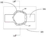
图2为根据本发明的一个示例性实施例的体声波谐振器的俯视图;2 is a top view of a bulk acoustic wave resonator according to an exemplary embodiment of the present invention;
图3为根据一个示例性实施例的沿图2中的1A-1A向截得的示意性截面图,其中压电层的两侧设置有上空气层和下空气层;3 is a schematic cross-sectional view taken along the
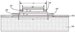
图4为根据一个可选示例性实施例的体声波谐振器沿图2中的1A-1A向截得的示意性截面图,其中仅含有上空气层;FIG. 4 is a schematic cross-sectional view of a bulk acoustic wave resonator taken along the
图5为根据一个可选示例性实施例的体声波谐振器沿图2中的1A-1A向截得的示意性截面图,其中仅含有下空气层;FIG. 5 is a schematic cross-sectional view of the BAW resonator taken along the
图6为图3中的A区域的等效机电模型;Fig. 6 is the equivalent electromechanical model of A area in Fig. 3;
图7为图3中的A区域的简化的等效机电模型;FIG. 7 is a simplified equivalent electromechanical model of the A region in FIG. 3;
图8为体声波谐振器S1的mBVD模型;Fig. 8 is the mBVD model of bulk acoustic wave resonator S1;
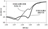
图9为图1中的滤波器的Band7Tx的插损频率特性仿真曲线,其中示出了谐振器的有效机电耦合系数不同的曲线,以及谐振器的有效机电耦合系数相同的曲线;FIG. 9 is a simulation curve of the insertion loss frequency characteristic of Band7Tx of the filter in FIG. 1 , wherein curves with different effective electromechanical coupling coefficients of the resonators and curves with the same effective electromechanical coupling coefficients of the resonators are shown;
图10为图1中的滤波器的Band7Rx的插损频率特性仿真曲线,其中示出了谐振器的有效机电耦合系数不同的曲线,以及谐振器的有效机电耦合系数相同的曲线;FIG. 10 is a simulation curve of the insertion loss frequency characteristic of Band7Rx of the filter in FIG. 1 , wherein curves with different effective electromechanical coupling coefficients of the resonators and curves with the same effective electromechanical coupling coefficients of the resonators are shown;
图11示出了谐振器的有效机电耦合系数不同的滤波器以及谐振器的有效机电耦合系数相同的滤波器的滚降曲线。FIG. 11 shows the roll-off curves of filters with different effective electromechanical coupling coefficients of the resonators and filters with the same effective electromechanical coupling coefficients of the resonators.
具体实施方式Detailed ways
下面通过实施例,并结合附图,对本发明的技术方案作进一步具体的说明。在说明书中,相同或相似的附图标号指示相同或相似的部件。下述参照附图对本发明实施方式的说明旨在对本发明的总体发明构思进行解释,而不应当理解为对本发明的一种限制。The technical solutions of the present invention will be further described in detail below through embodiments and in conjunction with the accompanying drawings. In the specification, the same or similar reference numerals refer to the same or similar parts. The following description of the embodiments of the present invention with reference to the accompanying drawings is intended to explain the general inventive concept of the present invention, and should not be construed as a limitation of the present invention.
图1为4阶滤波器的等效电路示意图,其中S1、S2、S3、S4为串联谐振器,其有效机电耦合系数为


图2为体声波谐振器S1的俯视图,此俯视图同时含上空气层和下空气层。体声波谐振器包括底电极102、底空气层109、压电层103、上空气层107、顶电极104。FIG. 2 is a top view of the bulk acoustic wave resonator S1, and the top view includes both an upper air layer and a lower air layer. The BAW resonator includes a
图3是沿着图2俯视图1A-1A所取的剖面图。体声波谐振器包括底电极102、下空气层109(对应于第一空腔)、压电层103、上空气层107(对应于第二空腔)、顶电极104。底电极102沉积在高阻硅衬底上,可将底电极102边缘刻蚀成斜面,此外底电极102的边缘还可以为阶梯状、垂直状或是其它相似的结构。图中A2所示区域为谐振器的有效区域,含顶电极104、上空气层107、压电层103、下空气层109、底电极102和高阻硅衬底;下空气层109的长度为A1、高度为d1;上空气层107的长度为A2、高度为d2。图3中A表示顶电极的区域。FIG. 3 is a cross-sectional view taken along the plan view of FIG. 2 in FIG. 1A-1A. The BAW resonator includes a
图3中A所示区域的等效机电模型如图6所示,其中Cair_TA为上空气层107的电容,Cair_BA为下空气层109的电容,Cp为压电层103的电容。上下空气电容的串联可直接用总空气电容Cair表示,故图3中A所示区域的等效机电模型也可用图7示意。图4、图5中A区域的等效机电模型同样可用图7示意。The equivalent electromechanical model of the region A in FIG. 3 is shown in FIG. 6 , where Cair_TA is the capacitance of the

体声波谐振器S1的BVD模型如图8所示,则谐振器阻抗Z为:The BVD model of the bulk acoustic wave resonator S1 is shown in Figure 8, and the resonator impedance Z is:

若Z等于0,可计算串联谐振频率为:If Z is equal to 0, the series resonance frequency can be calculated as:

若

通过公式一得知:若谐振器的其它参数一定,当上空气层107和下空气层109的高度d1或d2增加时,空气电容减小。According to
通过公式三得知:若空气电容减少,ω′s会增加;通过公式四得知:并联谐振频率ω′p不受空气电容的影响,始终保持不变。因此,谐振器的
对于图1中的各谐振器,通过调整每个谐振器的d1或d2,可调整其


以实现Band7(频段7)Tx性能为目标,对图1所示的四阶滤波器进行仿真优化,当分别控制串联谐振器的有效机电耦合系数为6.5%、6.0%、6.5%、6.5%,面积为:6.01k(这里的k表示1000平方微米,下同),6k,6.5k,6.5k;控制并联谐振器的有效机电耦合系数分别为:6.5%、6.1%、5.8%、5.8%,面积为:6k,10.7k,12.3k,7.7k时,其带宽要宽于所有谐振器均具有同一有效机电耦合系数6.12%的情况,如图9所示。以最大的


另一实施例中,以Band7(频段7)Rx频段要求进行滤波器优化,当分别控制串联谐振器的


基于以上,本发明提出了一种能够实现片内滤波器有效机电耦合系数


相应的,参照附图4,图4中示出的体声波谐振器包括:Correspondingly, referring to FIG. 4, the BAW resonator shown in FIG. 4 includes:
基底100;base 100;
声学镜101;
底电极102,设置在基底上方;a
顶电极104;和
压电层103,设置在底电极上方以及底电极与顶电极之间,The
其中:in:
所述压电层与所述顶电极之间设置有第二空腔(上空气层)107,其中,第二空腔具有第二宽度A2和第二高度d2;且A second cavity (upper air layer) 107 is disposed between the piezoelectric layer and the top electrode, wherein the second cavity has a second width A2 and a second height d2; and
所述声学镜、底电极、压电层、顶电极,以及所述第二空腔在谐振器厚度方向上的重叠区域构成谐振器的有效区域A2。The overlapping area of the acoustic mirror, the bottom electrode, the piezoelectric layer, the top electrode, and the second cavity in the thickness direction of the resonator constitutes an effective area A2 of the resonator.
可选的,所述第二空腔107在谐振器厚度方向上的投影落入所述声学镜101的区域内。Optionally, the projection of the
相应的,参见图5,本发明还提出了一种体声波谐振器,包括:Correspondingly, referring to FIG. 5 , the present invention also provides a bulk acoustic wave resonator, including:
基底;base;
底电极102,设置在基底上方;a
顶电极104;
压电层103,设置在底电极上方以及底电极与顶电极之间;和a
第一空腔109,设置在所述底电极与所述压电层之间,The
其中:in:
所述第一空腔、底电极、压电层和顶电极在谐振器厚度方向上的重叠区域构成谐振器的有效区域A;The overlapping area of the first cavity, the bottom electrode, the piezoelectric layer and the top electrode in the thickness direction of the resonator constitutes the effective area A of the resonator;
第一空腔109具有第一宽度A1和第一高度d1。The
相应的,本发明提出了一种调整上述体声波谐振器的有效机电耦合系数的方法,包括步骤:通过调整所述空腔的高度和/或宽度,调节所述有效机电耦合系数。例如,可以通过提高所述高度降低所述有效机电耦合系数。再如,可以通过降低所述高度提高所述有效机电耦合系数。Correspondingly, the present invention provides a method for adjusting the effective electromechanical coupling coefficient of the above-mentioned bulk acoustic wave resonator, comprising the steps of: adjusting the effective electromechanical coupling coefficient by adjusting the height and/or width of the cavity. For example, the effective electromechanical coupling coefficient can be reduced by increasing the height. For another example, the effective electromechanical coupling coefficient can be increased by reducing the height.
需要专门指出的是,这里的“所述宽度”,在存在第一宽度和第二宽度的情况下,表示第一宽度和/或第二宽度,而在仅有一个宽度的情况下,为该宽度;这里的“所述高度”,在存在第一高度和第二高度的情况下,表示第一高度和/或第二高度,而在仅有一个高度的情况下,为该高度。It should be specially pointed out that the "the width" here, in the presence of the first width and the second width, refers to the first width and/or the second width, and in the case of only one width, it refers to the Width; the "height" here, in the presence of the first height and the second height, means the first height and/or the second height, and in the case of only one height, the height.
相应的,本发明提出了一种滤波器,包括:串联支路,包括多个串联谐振器;多个并联支路,每个并联支路包括并联谐振器,其中:所述并联谐振器和所述多个串联谐振器中的至少一个谐振器的有效机电耦合系数不同于其他谐振器的有效机电耦合系数,所述至少一个谐振器为上述的体声波谐振器。Correspondingly, the present invention provides a filter, comprising: a series branch including a plurality of series resonators; a plurality of parallel branches, each parallel branch including a parallel resonator, wherein: the parallel resonator and the The effective electromechanical coupling coefficient of at least one resonator in the plurality of series resonators is different from the effective electromechanical coupling coefficient of other resonators, and the at least one resonator is the above-mentioned bulk acoustic wave resonator.
进一步的,所述并联谐振器和所述多个串联谐振器中的至少两个谐振器可为上述的谐振器,且所述至少两个谐振器基于所述宽度和/或所述高度的不同,而具有彼此不同的有效机电耦合系数。Further, at least two resonators in the parallel resonator and the plurality of series resonators may be the above-mentioned resonators, and the at least two resonators are different based on the width and/or the height , while having different effective electromechanical coupling coefficients from each other.
下面示例性的简单说明根据本发明的体声波谐振器的部件的材料。The materials of the components of the bulk acoustic wave resonator according to the present invention are exemplified briefly below.
在本发明中,电极组成材料可以是金(Au)、钨(W)、钼(Mo)、铂(Pt),钌(Ru)、铱(Ir)、钛钨(TiW)、铝(Al)、钛(Ti)、锇(Os)、镁(Mg)、金(Au)、钨(W)、钼(Mo)、铂(Pt)、钌(Ru)、铱(Ir)、锗(Ge)、铜(Cu)、铝(Al)、铬(Cr)、砷掺杂金等类似金属形成。In the present invention, the electrode composition material may be gold (Au), tungsten (W), molybdenum (Mo), platinum (Pt), ruthenium (Ru), iridium (Ir), titanium tungsten (TiW), aluminum (Al) , Titanium (Ti), Osmium (Os), Magnesium (Mg), Gold (Au), Tungsten (W), Molybdenum (Mo), Platinum (Pt), Ruthenium (Ru), Iridium (Ir), Germanium (Ge) , copper (Cu), aluminum (Al), chromium (Cr), arsenic doped gold and other similar metals.
在本发明中,压电层材料可以为氮化铝(AlN)、掺杂氮化铝(doped ALN)氧化锌(ZnO)、锆钛酸铅(PZT)、铌酸锂(LiNbO3)、石英(Quartz)、铌酸钾(KNbO3)或钽酸锂(LiTaO3)等材料,其中掺杂ALN至少含一种稀土元素,如钪(Sc)、钇(Y)、镁(Mg)、钛(Ti)、镧(La)、铈(Ce)、镨(Pr)、钕(Nd)、钷(Pm)、钐(Sm)、铕(Eu)、钆(Gd)、铽(Tb)、镝(Dy)、钬(Ho)、铒(Er)、铥(Tm)、镱(Yb)、镥(Lu)等。In the present invention, the piezoelectric layer material can be aluminum nitride (AlN), doped aluminum nitride (doped ALN) zinc oxide (ZnO), lead zirconate titanate (PZT), lithium niobate (LiNbO3), quartz ( Quartz), potassium niobate (KNbO3) or lithium tantalate (LiTaO3) and other materials, wherein the doped ALN contains at least one rare earth element, such as scandium (Sc), yttrium (Y), magnesium (Mg), titanium (Ti) , Lanthanum (La), Cerium (Ce), Praseodymium (Pr), Neodymium (Nd), Promethium (Pm), Samarium (Sm), Europium (Eu), Gadolinium (Gd), Terbium (Tb), Dysprosium (Dy) , holmium (Ho), erbium (Er), thulium (Tm), ytterbium (Yb), lutetium (Lu), etc.
在本发明中,基底材料包括但不限于:单晶硅(Si),砷化镓(GaAs),蓝宝石,石英等。In the present invention, the base material includes but is not limited to: single crystal silicon (Si), gallium arsenide (GaAs), sapphire, quartz, and the like.
本发明的实施例也涉及一种电子设备,包括上述的滤波器或者谐振器。需要指出的是,这里的电子设备,包括但不限于射频前端、滤波放大模块等中间产品,以及手机、WIFI、无人机等终端产品。Embodiments of the present invention also relate to an electronic device comprising the above-mentioned filter or resonator. It should be pointed out that the electronic equipment here includes but is not limited to intermediate products such as RF front-end, filter and amplifier modules, and terminal products such as mobile phones, WIFI, and drones.
尽管已经示出和描述了本发明的实施例,对于本领域的普通技术人员而言,可以理解在不脱离本发明的原理和精神的情况下可以对这些实施例进行变化,本发明的范围由所附权利要求及其等同物限定。Although embodiments of the present invention have been shown and described, it will be understood by those of ordinary skill in the art that changes may be made to these embodiments without departing from the principles and spirit of the invention, the scope of which is determined by It is defined by the appended claims and their equivalents.
Claims (11)
Priority Applications (1)
| Application Number | Priority Date | Filing Date | Title |
|---|---|---|---|
| CN201811558489.9ACN111355463A (en) | 2018-12-20 | 2018-12-20 | Device for Adjusting Effective Electromechanical Coupling Coefficient Based on Cavity Size |
Applications Claiming Priority (1)
| Application Number | Priority Date | Filing Date | Title |
|---|---|---|---|
| CN201811558489.9ACN111355463A (en) | 2018-12-20 | 2018-12-20 | Device for Adjusting Effective Electromechanical Coupling Coefficient Based on Cavity Size |
Publications (1)
| Publication Number | Publication Date |
|---|---|
| CN111355463Atrue CN111355463A (en) | 2020-06-30 |
Family
ID=71193601
Family Applications (1)
| Application Number | Title | Priority Date | Filing Date |
|---|---|---|---|
| CN201811558489.9APendingCN111355463A (en) | 2018-12-20 | 2018-12-20 | Device for Adjusting Effective Electromechanical Coupling Coefficient Based on Cavity Size |
Country Status (1)
| Country | Link |
|---|---|
| CN (1) | CN111355463A (en) |
Cited By (8)
| Publication number | Priority date | Publication date | Assignee | Title |
|---|---|---|---|---|
| CN113726307A (en)* | 2021-08-18 | 2021-11-30 | 武汉大学 | Ultra-high frequency resonator with adjustable effective electromechanical coupling coefficient |
| WO2022028401A1 (en)* | 2020-08-06 | 2022-02-10 | 诺思(天津)微系统有限责任公司 | Bulk acoustic resonator assembly having acoustic decoupling layer and manufacturing method, filter, and electronic device |
| CN114257208A (en)* | 2020-09-22 | 2022-03-29 | 诺思(天津)微系统有限责任公司 | Bulk acoustic wave resonator, bulk acoustic wave resonator assembly, electromechanical coupling coefficient difference adjusting method, filter, and electronic device |
| CN114337591A (en)* | 2021-09-18 | 2022-04-12 | 中国电子科技集团公司第五十五研究所 | Film bulk acoustic resonator with adjustable electromechanical coupling coefficient |
| CN114744974A (en)* | 2021-01-07 | 2022-07-12 | 诺思(天津)微系统有限责任公司 | Bulk acoustic wave resonator and its manufacturing method, filter and electronic equipment |
| WO2022152178A1 (en)* | 2021-01-13 | 2022-07-21 | 诺思(天津)微系统有限责任公司 | Filter, multiplexer, and electronic device |
| CN114894229A (en)* | 2022-04-26 | 2022-08-12 | 武汉敏声新技术有限公司 | A kind of thin-film bulk acoustic wave sensor and preparation method thereof |
| CN118740095A (en)* | 2024-06-24 | 2024-10-01 | 晨宸辰科技有限公司 | A resonant structure capable of suppressing spurious responses of multilayer SAW devices |
Citations (3)
| Publication number | Priority date | Publication date | Assignee | Title |
|---|---|---|---|---|
| CN101908865A (en)* | 2010-08-20 | 2010-12-08 | 庞慰 | Bulk wave resonator and its processing method |
| CN103607178A (en)* | 2013-09-17 | 2014-02-26 | 诺思(天津)微系统有限公司 | Film bulk wave resonator and method for raising quality factor of film bulk wave resonator |
| US20160164487A1 (en)* | 2014-12-05 | 2016-06-09 | Samsung Electro-Mechanics Co., Ltd. | Bulk acoustic wave filter |
- 2018
- 2018-12-20CNCN201811558489.9Apatent/CN111355463A/enactivePending
Patent Citations (3)
| Publication number | Priority date | Publication date | Assignee | Title |
|---|---|---|---|---|
| CN101908865A (en)* | 2010-08-20 | 2010-12-08 | 庞慰 | Bulk wave resonator and its processing method |
| CN103607178A (en)* | 2013-09-17 | 2014-02-26 | 诺思(天津)微系统有限公司 | Film bulk wave resonator and method for raising quality factor of film bulk wave resonator |
| US20160164487A1 (en)* | 2014-12-05 | 2016-06-09 | Samsung Electro-Mechanics Co., Ltd. | Bulk acoustic wave filter |
Cited By (11)
| Publication number | Priority date | Publication date | Assignee | Title |
|---|---|---|---|---|
| WO2022028401A1 (en)* | 2020-08-06 | 2022-02-10 | 诺思(天津)微系统有限责任公司 | Bulk acoustic resonator assembly having acoustic decoupling layer and manufacturing method, filter, and electronic device |
| CN114257208A (en)* | 2020-09-22 | 2022-03-29 | 诺思(天津)微系统有限责任公司 | Bulk acoustic wave resonator, bulk acoustic wave resonator assembly, electromechanical coupling coefficient difference adjusting method, filter, and electronic device |
| CN114744974A (en)* | 2021-01-07 | 2022-07-12 | 诺思(天津)微系统有限责任公司 | Bulk acoustic wave resonator and its manufacturing method, filter and electronic equipment |
| WO2022148387A1 (en)* | 2021-01-07 | 2022-07-14 | 诺思(天津)微系统有限责任公司 | Bulk acoustic wave resonator and manufacturing method therefor, filter, and electronic device |
| WO2022152178A1 (en)* | 2021-01-13 | 2022-07-21 | 诺思(天津)微系统有限责任公司 | Filter, multiplexer, and electronic device |
| CN113726307A (en)* | 2021-08-18 | 2021-11-30 | 武汉大学 | Ultra-high frequency resonator with adjustable effective electromechanical coupling coefficient |
| CN113726307B (en)* | 2021-08-18 | 2024-01-23 | 武汉敏声新技术有限公司 | Ultrahigh frequency resonator with adjustable effective electromechanical coupling coefficient |
| CN114337591A (en)* | 2021-09-18 | 2022-04-12 | 中国电子科技集团公司第五十五研究所 | Film bulk acoustic resonator with adjustable electromechanical coupling coefficient |
| CN114894229A (en)* | 2022-04-26 | 2022-08-12 | 武汉敏声新技术有限公司 | A kind of thin-film bulk acoustic wave sensor and preparation method thereof |
| CN114894229B (en)* | 2022-04-26 | 2024-05-03 | 武汉敏声新技术有限公司 | Film bulk acoustic wave sensor and preparation method thereof |
| CN118740095A (en)* | 2024-06-24 | 2024-10-01 | 晨宸辰科技有限公司 | A resonant structure capable of suppressing spurious responses of multilayer SAW devices |
Similar Documents
| Publication | Publication Date | Title |
|---|---|---|
| CN111355463A (en) | Device for Adjusting Effective Electromechanical Coupling Coefficient Based on Cavity Size | |
| CN110061712B (en) | Acoustic resonator, filter and electronic device comprising annular protrusion Liang Yan structure | |
| WO2021208925A1 (en) | Piezoelectric filter and out-of-band rejection improvement method therefor, multiplexer, and communication device | |
| EP4033660A1 (en) | Bulk acoustic resonator with adjusting layer, and filter and electronic device | |
| JP6105084B2 (en) | Method for manufacturing MEMS parts having aluminum nitride and scandium | |
| CN111193489B (en) | Bulk acoustic resonators, filters and electronic devices | |
| WO2021042741A1 (en) | Bulk acoustic wave resonator with piezoelectric layer having insert structure, and filter and electronic device | |
| WO2020140654A1 (en) | Apparatus and method for adjusting performance of acoustic resonator on the basis of beam and eave dimension | |
| US20240322783A1 (en) | Bulk acoustic wave resonance device and method for forming same, filtering device, and radio frequency front end device | |
| CN111564550B (en) | Semiconductor device, method of manufacturing the same, and electronic apparatus having the same | |
| WO2022028401A1 (en) | Bulk acoustic resonator assembly having acoustic decoupling layer and manufacturing method, filter, and electronic device | |
| US20220029605A1 (en) | Surface acoustic wave resonator and multiplexer including the same | |
| WO2020134804A1 (en) | Resonator with extension structure at connection portion of top electrode, filter and electronic device | |
| WO2022083352A1 (en) | Bulk acoustic resonator and assembly, filter, and electronic device | |
| CN114696773A (en) | Bulk acoustic wave resonator and manufacturing method, filter and electronic device | |
| CN111355464A (en) | Device for adjusting effective electromechanical coupling coefficient based on annular protrusion | |
| WO2020134803A1 (en) | Bulk acoustic wave resonator having asymmetric electrode thickness, filter, and electronic device | |
| CN111342808A (en) | Resonator, filter and electronic device based on element doping to reduce effective area | |
| US20220337212A1 (en) | Bulk acoustic wave resonance device and bulk acoustic wave filter | |
| CN111262547A (en) | Bulk Acoustic Resonators, MEMS Devices, Filters and Electronics | |
| CN111355470A (en) | Device for adjusting effective electromechanical coupling coefficient based on suspended eave size | |
| WO2022062910A1 (en) | Bulk acoustic resonator and assembly, method for adjusting electromechanical coupling coefficient difference, and filter and electronic device | |
| CN111130499B (en) | Broadband film cavity acoustic resonant filter | |
| CN114553169A (en) | Bulk acoustic wave resonator, filter and electronic device using convex structure to reduce acoustic impedance | |
| US20250300621A1 (en) | Bulk acoustic wave resonance device, filter device, and radio frequency front-end device |
Legal Events
| Date | Code | Title | Description |
|---|---|---|---|
| PB01 | Publication | ||
| PB01 | Publication | ||
| SE01 | Entry into force of request for substantive examination | ||
| SE01 | Entry into force of request for substantive examination |