CN111347916A - Charging and energy storage integrated battery replacement station - Google Patents
Charging and energy storage integrated battery replacement stationDownload PDFInfo
- Publication number
- CN111347916A CN111347916ACN201811572326.6ACN201811572326ACN111347916ACN 111347916 ACN111347916 ACN 111347916ACN 201811572326 ACN201811572326 ACN 201811572326ACN 111347916 ACN111347916 ACN 111347916A
- Authority
- CN
- China
- Prior art keywords
- energy storage
- charging
- direct current
- battery
- charged
- Prior art date
- Legal status (The legal status is an assumption and is not a legal conclusion. Google has not performed a legal analysis and makes no representation as to the accuracy of the status listed.)
- Pending
Links
Images


Classifications
- Y—GENERAL TAGGING OF NEW TECHNOLOGICAL DEVELOPMENTS; GENERAL TAGGING OF CROSS-SECTIONAL TECHNOLOGIES SPANNING OVER SEVERAL SECTIONS OF THE IPC; TECHNICAL SUBJECTS COVERED BY FORMER USPC CROSS-REFERENCE ART COLLECTIONS [XRACs] AND DIGESTS
- Y02—TECHNOLOGIES OR APPLICATIONS FOR MITIGATION OR ADAPTATION AGAINST CLIMATE CHANGE
- Y02T—CLIMATE CHANGE MITIGATION TECHNOLOGIES RELATED TO TRANSPORTATION
- Y02T10/00—Road transport of goods or passengers
- Y02T10/60—Other road transportation technologies with climate change mitigation effect
- Y02T10/70—Energy storage systems for electromobility, e.g. batteries
- Y—GENERAL TAGGING OF NEW TECHNOLOGICAL DEVELOPMENTS; GENERAL TAGGING OF CROSS-SECTIONAL TECHNOLOGIES SPANNING OVER SEVERAL SECTIONS OF THE IPC; TECHNICAL SUBJECTS COVERED BY FORMER USPC CROSS-REFERENCE ART COLLECTIONS [XRACs] AND DIGESTS
- Y02—TECHNOLOGIES OR APPLICATIONS FOR MITIGATION OR ADAPTATION AGAINST CLIMATE CHANGE
- Y02T—CLIMATE CHANGE MITIGATION TECHNOLOGIES RELATED TO TRANSPORTATION
- Y02T10/00—Road transport of goods or passengers
- Y02T10/60—Other road transportation technologies with climate change mitigation effect
- Y02T10/7072—Electromobility specific charging systems or methods for batteries, ultracapacitors, supercapacitors or double-layer capacitors
- Y—GENERAL TAGGING OF NEW TECHNOLOGICAL DEVELOPMENTS; GENERAL TAGGING OF CROSS-SECTIONAL TECHNOLOGIES SPANNING OVER SEVERAL SECTIONS OF THE IPC; TECHNICAL SUBJECTS COVERED BY FORMER USPC CROSS-REFERENCE ART COLLECTIONS [XRACs] AND DIGESTS
- Y02—TECHNOLOGIES OR APPLICATIONS FOR MITIGATION OR ADAPTATION AGAINST CLIMATE CHANGE
- Y02T—CLIMATE CHANGE MITIGATION TECHNOLOGIES RELATED TO TRANSPORTATION
- Y02T90/00—Enabling technologies or technologies with a potential or indirect contribution to GHG emissions mitigation
- Y02T90/10—Technologies relating to charging of electric vehicles
- Y02T90/12—Electric charging stations
Landscapes
- Charge And Discharge Circuits For Batteries Or The Like (AREA)
Abstract
Translated fromChinese
Description
Translated fromChinese技术领域technical field
本发明涉及电动汽车换电领域,尤其涉及一种充电和储能一体式换电站。The invention relates to the field of electric vehicle power exchange, in particular to a charging and energy storage integrated power exchange station.
背景技术Background technique
电动汽车(BEV)是指以车载电源为动力,用电机驱动车轮行驶的车辆。由于具有结构简单、节能环保、噪音小等优点,电动汽车的市场普及率越来越高。随着电动汽车的推广,如何为电动汽车进行及时充电称为制约其发展的重要因素。Electric vehicle (BEV) refers to a vehicle powered by an on-board power supply and driven by a motor to drive the wheels. Due to the advantages of simple structure, energy saving and environmental protection, and low noise, the market penetration rate of electric vehicles is getting higher and higher. With the promotion of electric vehicles, how to charge electric vehicles in time is an important factor restricting their development.
现有技术中通常采用动力电池充电或动力电池换电的方式实现对电动汽车运行里程的延续。动力电池充电方式是指利用充电桩对电动汽车的动力电池进行充电,这种方式通常需要较长的时间,容易造成充电车辆排队拥挤,严重影响了用户体验。动力电池换电方式是指直接用充满电的动力电池更换电力耗尽的动力电池,然而,随着电动汽车的电池比能量(即单位重量或单位体积的电池所产生的能量)的不断提升,现有的充电机功率很难满足在数分钟(例如3至5分钟)内换电频次的需求,尤其是在换电高峰期,电网能承受的负荷接近满负荷,此时很难提供较大的充电电流给电力耗尽的电池充电,因此,严重影响了换电站的换电频次,导致电动汽车用户排队严重;若提前准备更多的备份电池,则会增加换电站的运营成本,另外,当换电站的体积有限制时,备份电池的数量也会受到限制。In the prior art, the continuation of the running range of the electric vehicle is usually realized by charging the power battery or exchanging the power of the power battery. The power battery charging method refers to the use of charging piles to charge the power battery of an electric vehicle. This method usually takes a long time, and it is easy to cause crowded queues of charging vehicles, which seriously affects the user experience. The power battery replacement method refers to directly replacing the exhausted power battery with a fully charged power battery. However, with the continuous improvement of the battery specific energy of electric vehicles (that is, the energy generated by the battery per unit weight or unit volume), The power of the existing chargers is difficult to meet the demand for the frequency of power exchange within a few minutes (such as 3 to 5 minutes). Therefore, the frequency of battery swapping at the swapping station is seriously affected, resulting in serious queues for electric vehicle users; if more backup batteries are prepared in advance, the operating cost of the swapping station will increase. In addition, When the size of the swap station is limited, the number of backup batteries will also be limited.
如何提供一种在降低换电站运营成本的前提下提高换电频次的换电站是目前亟待解决的问题。How to provide a power exchange station that can increase the frequency of power exchange on the premise of reducing the operating cost of the power exchange station is an urgent problem to be solved at present.
发明内容SUMMARY OF THE INVENTION
本发明要解决的技术问题是为了克服现有技术中换电站的换电频次受到制约的缺陷,提供一种充电和储能一体式换电站。The technical problem to be solved by the present invention is to provide a charging and energy storage integrated power exchange station in order to overcome the defect that the power exchange frequency of the power exchange station in the prior art is restricted.
本发明是通过下述技术方案来解决上述技术问题:The present invention solves the above-mentioned technical problems through the following technical solutions:
一种充电和储能一体式换电站,所述换电站包括:A charging and energy storage integrated power exchange station, the power exchange station includes:
充电单元,所述充电单元用于接收电网的交流电,并将所述交流电转换为第一直流电,所述第一直流电用于为待充电电池充电;a charging unit, configured to receive alternating current from a power grid and convert the alternating current into first direct current, where the first direct current is used to charge the battery to be charged;
储能单元,所述储能单元用于接收和存储所述电网的交流电,并将所述交流电转换为第二直流电,所述第二直流电用于为储能电池充电;an energy storage unit, the energy storage unit is used for receiving and storing the alternating current of the power grid, and converting the alternating current into a second direct current, and the second direct current is used for charging the energy storage battery;
控制单元,所述控制单元用于接收控制指令,并根据所述控制指令设定是否由所述第一直流电给所述待充电电池充电,和/或是否由所述储能电池给所述待充电电池充电。a control unit, the control unit is configured to receive a control command, and set according to the control command whether to charge the battery to be charged by the first direct current, and/or whether to charge the battery to be charged by the energy storage battery Rechargeable battery charge.
较佳地,当所述电网满负荷运行时,所述控制指令设定由所述第一直流电以及所述储能电池给所述待充电电池充电;当所述电网未满负荷运行时,所述控制指令设定由所述第一直流电给所述待充电电池充电。Preferably, when the power grid is running at full load, the control instruction sets the battery to be charged by the first direct current and the energy storage battery; when the power grid is not running at full load, all The control instruction sets that the battery to be charged is charged by the first direct current.
较佳地,所述充电单元包括:Preferably, the charging unit includes:
变压模块,所述变压模块的输入端接收所述电网的交流电,所述变压模块将所述交流电转换为所述第一直流电,所述第一直流电由所述变压模块的输出端输出;a transformer module, the input terminal of the transformer module receives the alternating current of the power grid, the transformer module converts the alternating current into the first direct current, and the first direct current is supplied by the output terminal of the transformer module output;
直流母线,所述直流母线接收所述第一直流电;a direct current bus, the direct current bus receiving the first direct current;
电池仓,所述电池仓具有充电接口,所述充电接口与所述直流母线连接,所述电池仓用于存放所述待充电电池,所述待充电电池接收所述第一直流电。A battery compartment, the battery compartment has a charging interface, the charging interface is connected with the DC bus, the battery compartment is used for storing the battery to be charged, and the battery to be charged receives the first direct current.
较佳地,所述变压模块包括:Preferably, the transformer module includes:
标准变压模块,所述标准变压模块的输入端接收所述电网的交流电,所述标准变压模块的输出端直接与所述直流母线连接;a standard transformer module, the input end of the standard transformer module receives the alternating current of the power grid, and the output end of the standard transformer module is directly connected to the DC bus;
机动变压模块,所述机动变压模块的输入端接收所述电网的交流电,所述机动变压模块的输出端连接选通开关的第一端,所述选通开关的第二端连接所述直流母线。A motorized transformer module, the input end of the motorized transformer module receives the alternating current of the power grid, the output end of the motorized transformer module is connected to the first end of the gating switch, and the second end of the gating switch is connected to the the DC bus.
较佳地,所述变压模块的数量为N1,不同的所述变压模块输出不同的第一直流电,其中,N1为正整数。Preferably, the number of the transformer modules is N1, and different transformer modules output different first direct currents, wherein N1 is a positive integer.
较佳地,所述储能单元包括:Preferably, the energy storage unit includes:
储能变流器,所述储能变流器用于接收所述电网的交流电,并输出所述第二直流电;an energy storage converter, the energy storage converter is configured to receive the alternating current of the power grid and output the second direct current;
直流调整模块,所述直流调整模块用于接收所述第二直流电,并输出调整后直流电,所述调整后直流电的电流值小于所述第二直流电的电流值,所述调整后直流电用于为所述储能电池充电。A DC adjustment module, the DC adjustment module is used to receive the second DC power and output the adjusted DC power, the current value of the adjusted DC power is smaller than the current value of the second DC power, and the adjusted DC power is used for The energy storage battery is charged.
较佳地,所述储能电池包括并联的N2个储能子电池,其中,N2为正整数。Preferably, the energy storage battery includes N2 energy storage sub-batteries connected in parallel, wherein N2 is a positive integer.
较佳地,所述充电单元的输入端与所述储能单元的输入端连接于同一条交流母线,所述交流母线与所述电网连接。Preferably, the input end of the charging unit and the input end of the energy storage unit are connected to the same AC bus, and the AC bus is connected to the power grid.
较佳地,所述充电单元通过第一隔离开关与所述交流母线连接,和/或所述储能单元通过第二隔离开关与所述交流母线连接,和/或所述电网通过第三隔离开关与所述交流母线连接。Preferably, the charging unit is connected to the AC bus through a first isolation switch, and/or the energy storage unit is connected to the AC bus through a second isolation switch, and/or the power grid is connected to the AC bus through a third isolation switch. A switch is connected to the AC bus.
较佳地,所述直流调整模块的数量为N3,不同的所述直流调整模块输出不同的调整后直流电,其中,N3为正整数。Preferably, the number of the DC adjustment modules is N3, and different DC adjustment modules output different adjusted DC currents, wherein N3 is a positive integer.
较佳地,所述充电单元与所述储能单元共同安装于所述换电站内的同一个集装箱内。Preferably, the charging unit and the energy storage unit are installed together in the same container in the power exchange station.
本发明的积极进步效果在于:本发明技术方案通过在换电站内设置充电单元以及储能单元,根据电网的不同负荷状态来调整对待充电电池的充电策略。由此,可以及时有效的为待充电车辆进行充电,提高了换电频次,缓解了充电高峰时间段内待充电车辆排队拥挤的情况,提高了用户体验。The positive improvement effect of the present invention is that the technical solution of the present invention adjusts the charging strategy of the battery to be recharged according to different load states of the power grid by arranging the charging unit and the energy storage unit in the power exchange station. As a result, the vehicles to be charged can be charged in a timely and effective manner, the frequency of battery replacement is increased, the crowded queue of vehicles to be charged during the peak charging time period is alleviated, and the user experience is improved.
进一步地,本发明技术方案通过设置标准变压模块以及机动变压模块,可以便捷地调整提供给直流母线的电力功率,从而可以实现对待充电车辆的柔性充电,提高了充电的灵活性。Further, the technical solution of the present invention can conveniently adjust the electric power provided to the DC bus by setting the standard transformer module and the motor transformer module, thereby realizing flexible charging of the vehicle to be charged and improving the flexibility of charging.
进一步地,本发明技术方案中充电单元和储能单元采用模块设计成组,能够实现充电单元以及储能单元的自由组合,扩展性能良好,有利于优化换电站的建设成本。Further, in the technical solution of the present invention, the charging unit and the energy storage unit are designed into groups by modules, which can realize the free combination of the charging unit and the energy storage unit, and has good expansion performance, which is conducive to optimizing the construction cost of the power exchange station.
附图说明Description of drawings
图1为本发明实施例1的一种充电和储能一体式换电站的结构示意图。FIG. 1 is a schematic structural diagram of an integrated charging and energy storage power exchange station according to
图2为本发明实施例2的一种充电和储能一体式换电站的结构示意图。FIG. 2 is a schematic structural diagram of an integrated charging and energy storage power exchange station according to
图3是本发明实施例2的第一种非限制性具体实施方式的结构示意图。FIG. 3 is a schematic structural diagram of a first non-limiting specific implementation manner of
图4是本发明实施例2的第二种非限制性具体实施方式的结构示意图。FIG. 4 is a schematic structural diagram of a second non-limiting specific implementation manner of
图5是本发明实施例2的第三种非限制性具体实施方式的结构示意图。FIG. 5 is a schematic structural diagram of a third non-limiting specific implementation manner of
具体实施方式Detailed ways
下面通过实施例的方式进一步说明本发明,但并不因此将本发明限制在所述的实施例范围之中。The present invention is further described below by way of examples, but the present invention is not limited to the scope of the described examples.
实施例1Example 1
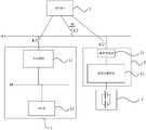
一种充电和储能一体式换电站,如图1所示,所述换电站可以包括:A charging and energy storage integrated power exchange station, as shown in Figure 1, the power exchange station may include:
充电单元1,所述充电单元1用于接收电网W的交流电,并将所述交流电转换为第一直流电,所述第一直流电用于为待充电电池充电;a
储能单元2,所述储能单元2用于接收和存储所述电网W的交流电,并将所述交流电转换为第二直流电,所述第二直流电用于为储能电池4充电;an
控制单元3,所述控制单元3用于接收控制指令,并根据所述控制指令设定是否由所述第一直流电给所述待充电电池充电,和/或是否由所述储能电池4给所述待充电电池充电。
本实施例中,所述充电单元1与所述储能单元2可以共同安装于所述换电站内的同一个集装箱内。In this embodiment, the
进一步地,所述充电单元1的输入端与所述储能单元2的输入端可以连接于同一条交流母线A1,所述交流母线A1与电网W连接。Further, the input end of the
具体地,所述充电单元1可以通过第一隔离开关K1与所述交流母线A1连接,和/或所述储能单元2可以通过第二隔离开关K2与所述交流母线A1连接,和/或所述电网W可以通过第三隔离开关K3与所述交流母线A1连接。Specifically, the
进一步地,所述控制单元3可以具有人机交互界面,用户在所述人机交互界面上可以根据具体需求而选择不同的控制指令或者输入不同的控制指令。Further, the
具体地,所述控制指令可以由文字输入或者语音输入,相应的,当所述控制指令由文字输入时,所述控制单元3还包括文字识别装置,以识别用户输入的文字指令;当所述控制指令由语音输入时,所述控制单元3还包括语音识别装置,以识别用户的语音指令。Specifically, the control command can be input by text or voice. Correspondingly, when the control command is input by text, the
可以理解的是,本领域技术人员可以根据具体需求而适应性的选择相应的控制指令的输入形式,例如,还可以采用手势输入的方式,或者,还可以将控制单元3与移动终端中的App相互绑定,在App中输入控制指令,通过移动终端与控制单元3之间的通信,将用户在App中输入的控制指令无线传递给控制单元3。本发明实施例对控制指令的具体输入形式不作限制。It can be understood that those skilled in the art can adaptively select the input form of the corresponding control instruction according to specific needs, for example, gesture input can also be used, or the
所述控制指令可以控制所述待充电电池的电力来源。具体地,当所述电网W满负荷运行时,所述控制指令可以设定由所述第一直流电以及所述储能电池4给所述待充电电池充电;当所述电网W未满负荷运行时,所述控制指令可以设定由所述第一直流电给所述待充电电池充电。The control instruction can control the power source of the battery to be charged. Specifically, when the power grid W is running at full load, the control instruction may set the battery to be charged by the first direct current and the
进一步地,所述充电单元1可以包括:变压模块11,所述变压模块11的输入端接收所述电网W的交流电,所述变压模块11将所述交流电转换为所述第一直流电,所述第一直流电由所述变压模块11的输出端输出;直流母线M,所述直流母线M接收所述第一直流电;电池仓12,所述电池仓12具有充电接口,所述充电接口与所述直流母线M连接,所述电池仓12用于存放所述待充电电池,所述待充电电池接收所述第一直流电。Further, the charging
进一步地,所述变压模块11的数量可以为N1,其中,N1为正整数。优选地,所述变压模块11的数量为多个,不同的所述变压模块11可以输出不同的第一直流电。Further, the number of the transformer modules 11 may be N1, where N1 is a positive integer. Preferably, the number of the transformer modules 11 is multiple, and different transformer modules 11 can output different first direct currents.
具体地,所述变压模块11可以是变压器,所述变压器可以接收电网W的交流电(例如:380V交流电)。所述变压器的容量可以根据具体应用场合而适应性的设置。当所述充电单元1包括多个变压器时,每个变压器的容量可以相同也可以不相同。Specifically, the transformer module 11 may be a transformer, and the transformer may receive alternating current (eg, 380V alternating current) of the power grid W. The capacity of the transformer can be adaptively set according to specific applications. When the charging
需要说明的是,N1的具体数值的设置可以根据换电站的体积以及换电站需服务的用户数量等因素而综合考量,本发明实施例对此不作限制。It should be noted that, the setting of the specific value of N1 may be comprehensively considered according to factors such as the volume of the swap station and the number of users to be served by the swap station, which is not limited in this embodiment of the present invention.
所述电池仓12用于放置待充电电池,充电时,所述电池仓12内的充电接口与所述待充电电池连接,所述待充电电池通过所述充电接口接收来自于直流母线M的第一直流电。The
进一步地,所述储能单元2可以包括:储能变流器21,所述储能变流器21用于接收所述电网的交流电,并输出所述第二直流电;直流调整模块22,所述直流调整模块22用于接收所述第二直流电,并输出调整后直流电,所述调整后直流电的电流值小于所述第二直流电的电流值,所述调整后直流电用于为所述储能电池4充电。Further, the
本实施例中,所述储能变流器21可以选用100KW储能变流器。所述直流调整模块22可以为DC/DC变换模块,所述DC/DC变换模块可以将所述储能变流器21输出的高电压直流转换为低电压直流,以满足为储能电池4充电的需求。In this embodiment, the
需要说明的是,本发明实施例中的“高电压”和“低电压”的电压值不做具体限定,只要高电压的电压值高于低电压的电压值即可。It should be noted that the voltage values of “high voltage” and “low voltage” in the embodiments of the present invention are not specifically limited, as long as the voltage value of the high voltage is higher than the voltage value of the low voltage.
进一步地,所述直流调整模块22的数量可以为多个,多个所述直流调整模块22的容量可以相同也可以不同。相应地,当多个直流调整模块22的容量相同时,其可以输出相同的调整后直流电;当多个直流调整模块的容量不同时,其可以输出不同的调整后直流电。Further, the number of the
进一步地,所述储能电池4可以包括并联的N2个储能子电池,其中,N2为正整数。更进一步地,可以为每一个储能子电池均设置一个储能工位。Further, the
需要说明的是,N2的具体数值的设置可以根据换电站的体积以及换电站需服务的用户数量等因素而综合考量,本发明实施例对此不作限制。It should be noted that, the setting of the specific value of N2 may be comprehensively considered according to factors such as the volume of the swap station and the number of users to be served by the swap station, which is not limited in this embodiment of the present invention.
本发明实施例的技术方案在实施时可以及时有效的为待充电车辆进行充电,提高了换电频次,缓解了充电高峰时间段内待充电车辆排队拥挤的情况,提高了用户体验。另外,所述充电单元和储能单元采用模块可以设计成组,能够实现充电单元以及储能单元的自由组合,扩展性能良好,有利于优化换电站的建设成本。The technical solutions of the embodiments of the present invention can charge the vehicles to be charged in a timely and effective manner when implemented, increase the frequency of battery replacement, alleviate the crowded queue of vehicles to be charged during the peak charging time period, and improve the user experience. In addition, the charging unit and the energy storage unit can be designed into groups by using modules, which can realize the free combination of the charging unit and the energy storage unit, and has good expansion performance, which is conducive to optimizing the construction cost of the power exchange station.
实施例2Example 2
一种充电和储能一体式换电站,本实施例的换电站是在实施例1基础上的进一步改进,如图2所示,所述换电站的变压模块可以包括:A charging and energy storage integrated power exchange station. The power exchange station of this embodiment is a further improvement on the basis of
标准变压模块111,所述标准变压模块111的输入端接收所述电网W的交流电,所述标准变压模块111的输出端直接与所述直流母线M连接;a
机动变压模块112,所述机动变压模块112的输入端接收所述电网W的交流电,所述机动变压模块112的输出端连接选通开关S的第一端,所述选通开关S的第二端连接所述直流母线M。A motorized transformer module 112, the input end of the motorized transformer module 112 receives the alternating current of the power grid W, and the output end of the motorized transformer module 112 is connected to the first end of the gating switch S, the gating switch S The second end of is connected to the DC bus M.
进一步地,所述选通开关S可以包括多个选通子开关,所述机动变压模块112可以通过不同的选通子开关连接至不同的直流母线M。Further, the gating switch S may include a plurality of gating sub-switches, and the motorized transformer module 112 may be connected to different DC busbars M through different gating sub-switches.
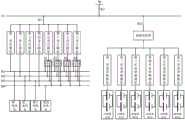
请参考图3,图3是实施例2的第一个非限制性的具体实施方式的示意图。该具体实施方式应用在所述电网W未满负荷运行时,所述控制指令可以设定由所述第一直流电给所述待充电电池充电。Please refer to FIG. 3 , which is a schematic diagram of a first non-limiting specific implementation manner of
其中,共设置有四条直流母线M1、M2、M3、M4,共设置有8个变压模块,依次为第一变压模块、第二变压模块、第三变压模块、……、第八变压模块,8个变压模块构成了变压模块组。其中,第一变压模块、第二变压模块、第三变压模块以及第四变压模块为标准变压模块,其分别对应连接于相应的直流母线,第五变压模块、第六变压模块、第七变压模块、第八变压模块为机动变压模块,其分别通过选通开关S1、S2、S3、S4连接于直流母线M1、M2、M3、M4;第一电池仓、第二电池仓、第三电池仓以及第四电池仓内分别放置有待充电电池。Among them, there are a total of four DC busbars M1, M2, M3, M4, and a total of 8 transformer modules, which are the first transformer module, the second transformer module, the third transformer module, ..., the eighth transformer module. Transformer module, 8 transformer modules constitute a transformer module group. Among them, the first transformer module, the second transformer module, the third transformer module and the fourth transformer module are standard transformer modules, which are respectively connected to the corresponding DC bus. The transformer module, the seventh transformer module, and the eighth transformer module are motor transformer modules, which are respectively connected to the DC busbars M1, M2, M3, and M4 through the gate switches S1, S2, S3, and S4; the first battery compartment, Batteries to be charged are respectively placed in the second battery compartment, the third battery compartment and the fourth battery compartment.
此时,第一隔离开关K1以及第三隔离开关K3闭合,第二隔离开关K2断开,电网W通过交流母线A1给图示的多个变压模块供电,每一条直流母线都与各自对应的标准变压模块直接连接。At this time, the first isolating switch K1 and the third isolating switch K3 are closed, the second isolating switch K2 is open, and the power grid W supplies power to the plurality of transformer modules shown in the figure through the AC bus A1, and each DC bus is associated with its corresponding Standard transformer modules are directly connected.
若第一电池仓与第三电池仓中的电池容量较大,而且需要较快速的充电,则可以将机动变压模块投入使用。具体实施时,第五变压模块通过选通开关K1中的子开关为第一直流母线M1供电,第六变压模块通过选通开关K2中的子开关为第三直流母线M3供电。If the capacity of the batteries in the first battery compartment and the third battery compartment is larger and faster charging is required, the motorized transformer module can be put into use. In specific implementation, the fifth transformer module supplies power to the first DC bus M1 through the sub-switch in the gating switch K1, and the sixth transformer module supplies power to the third DC bus M3 through the sub-switch in the gating switch K2.
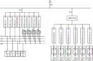
请参考图4,图4是实施例2中的第二个非限制性的具体实施方式的示意图。该具体实施方式应用在电网W满负荷运行的场景,用户发出控制指令,所述控制指令可以设定由第一直流电以及所述储能电池给所述待充电电池充电。Please refer to FIG. 4 , which is a schematic diagram of a second non-limiting specific implementation manner in
此时,第一隔离开关K1、第二隔离开关K2以及第三隔离开关K3闭合,电网W通过交流母线A1给图示的多个变压模块供电,多组储能电池输出的直流电通过直流调整模块以及储能变流器后变换为交流电,并接入所述交流母线A1,供给交流母线A1的电能再经过第一隔离开关K1为多个变压模块供电。At this time, the first isolation switch K1, the second isolation switch K2 and the third isolation switch K3 are closed, the power grid W supplies power to the multiple transformer modules shown in the figure through the AC bus A1, and the DC power output by the multiple groups of energy storage batteries is adjusted by DC The module and the energy storage converter are then converted into alternating current and connected to the alternating current bus A1, and the electric energy supplied to the alternating current bus A1 then supplies power to a plurality of transformer modules through the first isolation switch K1.
在该场景下,若第二电池仓内的待充电电池容量较大,而且需要较快速的充电,则可以将机动变压模块投入使用,具体实施时,第五变压模块通过选通开关S1中的子开关为第二直流母线M2供电,第八变压模块通过选通开关S4中的子开关为第二直流母线M2供电。In this scenario, if the capacity of the battery to be recharged in the second battery compartment is large and requires faster charging, the motorized transformer module can be put into use. The sub-switch in S4 supplies power to the second DC bus M2, and the eighth transformer module supplies power to the second DC bus M2 through the sub-switch in the gating switch S4.
请参考图5,图5是实施例2中的第三个非限制性的具体实施方式的示意图。该具体实施方式应用在没有待充电电池需要充电,只为储能电池进行充电的场景,此场景通常为深夜用电低谷期间,可以只使用较低的电价为储能电池充电,为白天在用电高峰期为待充电电池充电做准备。Please refer to FIG. 5 , which is a schematic diagram of a third non-limiting specific implementation manner in
在此场景中,所述第一隔离开关K1断开,所述第二隔离开关K2以及第三隔离开关K3闭合,电网W通过第三隔离开关K3将电能供给交流母线A1,交流母线A1接收的电能通过储能变流器以及多个直流调整模块供给多个储能电池。In this scenario, the first isolating switch K1 is turned off, the second isolating switch K2 and the third isolating switch K3 are closed, the power grid W supplies power to the AC bus A1 through the third isolating switch K3, and the AC bus A1 receives the electrical energy. Electric energy is supplied to a plurality of energy storage batteries through an energy storage converter and a plurality of DC adjustment modules.
需要说明的是,上述三种具体实施方式只是示例性的介绍各个隔离开关、选通开关以及机动变压模块相互配合的方式。其中,各个隔离开关以及各个选通开关的开合可以根据具体需求来进行设置,变压模块、电池仓、直流调整模块、储能电池的数量也可以根据具体地应用场景进行增加或减少,例如:还可以将变压模块设置为16个(其中可以包括10个标准变压模块和6个机动变压模块),还可以将直流调整模块设置为8个,还可以将每一个储能电池设置为由4个储能子电池并联组成,本实施例对此都不作限制。It should be noted that the above-mentioned three specific implementation manners are only illustrative of the ways in which the isolation switches, the gating switches and the motorized transformer modules cooperate with each other. Among them, the opening and closing of each isolation switch and each gate switch can be set according to specific needs, and the number of transformer modules, battery compartments, DC adjustment modules, and energy storage batteries can also be increased or decreased according to specific application scenarios, such as : The number of transformer modules can also be set to 16 (including 10 standard transformer modules and 6 motorized transformer modules), the number of DC adjustment modules can also be set to 8, and each energy storage battery can be set to Since it is composed of four energy storage sub-batteries in parallel, this embodiment does not limit this.
本实施例的技术方案通过设置标准变压模块以及机动变压模块,可以便捷地调整提供给直流母线的电力功率,从而可以实现对待充电车辆的柔性充电,并且可以根据需要灵活调整各个模块的数量和组合方式,有效提高了换电站设计的灵活性。The technical solution of this embodiment can easily adjust the electric power provided to the DC bus by setting the standard transformer module and the motor transformer module, so that flexible charging of the vehicle to be charged can be realized, and the number of each module can be flexibly adjusted as required And the combination method effectively improves the flexibility of the design of the power exchange station.
虽然以上描述了本发明的具体实施方式,但是本领域的技术人员应当理解,这仅是举例说明,本发明的保护范围是由所附权利要求书限定的。本领域的技术人员在不背离本发明的原理和实质的前提下,可以对这些实施方式做出多种变更或修改,但这些变更和修改均落入本发明的保护范围。Although the specific embodiments of the present invention are described above, those skilled in the art should understand that this is only an illustration, and the protection scope of the present invention is defined by the appended claims. Those skilled in the art can make various changes or modifications to these embodiments without departing from the principle and essence of the present invention, but these changes and modifications all fall within the protection scope of the present invention.
Claims (11)
Priority Applications (1)
| Application Number | Priority Date | Filing Date | Title |
|---|---|---|---|
| CN201811572326.6ACN111347916A (en) | 2018-12-21 | 2018-12-21 | Charging and energy storage integrated battery replacement station |
Applications Claiming Priority (1)
| Application Number | Priority Date | Filing Date | Title |
|---|---|---|---|
| CN201811572326.6ACN111347916A (en) | 2018-12-21 | 2018-12-21 | Charging and energy storage integrated battery replacement station |
Publications (1)
| Publication Number | Publication Date |
|---|---|
| CN111347916Atrue CN111347916A (en) | 2020-06-30 |
Family
ID=71193662
Family Applications (1)
| Application Number | Title | Priority Date | Filing Date |
|---|---|---|---|
| CN201811572326.6APendingCN111347916A (en) | 2018-12-21 | 2018-12-21 | Charging and energy storage integrated battery replacement station |
Country Status (1)
| Country | Link |
|---|---|
| CN (1) | CN111347916A (en) |
Cited By (4)
| Publication number | Priority date | Publication date | Assignee | Title |
|---|---|---|---|---|
| CN113422419A (en)* | 2021-08-24 | 2021-09-21 | 中国华能集团清洁能源技术研究院有限公司 | Battery changing station |
| CN114123426A (en)* | 2021-12-09 | 2022-03-01 | 浙江吉智新能源汽车科技有限公司 | Charging system of battery replacement station |
| CN115152122A (en)* | 2021-06-28 | 2022-10-04 | 华为数字能源技术有限公司 | A charging cabinet, battery pack and charging system |
| CN118182200A (en)* | 2024-04-10 | 2024-06-14 | 国网山东省电力公司东营供电公司 | Wind, solar, storage, charging, replacement and inspection integrated service station |
Citations (5)
| Publication number | Priority date | Publication date | Assignee | Title |
|---|---|---|---|---|
| CN102290841A (en)* | 2011-08-13 | 2011-12-21 | 罗俊亚 | Peak clipping and valley filling electric vehicle swapping station for distribution network |
| CN207150182U (en)* | 2017-09-20 | 2018-03-27 | 重庆聚陆新能源有限公司 | A kind of direct current micro-grid system based on DC/DC converter time-sharing multiplexs |
| CN108365623A (en)* | 2018-05-11 | 2018-08-03 | 宁波利维能储能系统有限公司 | Electric vehicle changes the transmission system of electricity and energy storage station |
| CN207902206U (en)* | 2018-02-09 | 2018-09-25 | 江苏万帮德和新能源科技股份有限公司 | A kind of integration charging system |
| CN108767892A (en)* | 2018-04-23 | 2018-11-06 | 力神动力电池系统有限公司 | A kind of charging station system of novel electric vehicle |
- 2018
- 2018-12-21CNCN201811572326.6Apatent/CN111347916A/enactivePending
Patent Citations (5)
| Publication number | Priority date | Publication date | Assignee | Title |
|---|---|---|---|---|
| CN102290841A (en)* | 2011-08-13 | 2011-12-21 | 罗俊亚 | Peak clipping and valley filling electric vehicle swapping station for distribution network |
| CN207150182U (en)* | 2017-09-20 | 2018-03-27 | 重庆聚陆新能源有限公司 | A kind of direct current micro-grid system based on DC/DC converter time-sharing multiplexs |
| CN207902206U (en)* | 2018-02-09 | 2018-09-25 | 江苏万帮德和新能源科技股份有限公司 | A kind of integration charging system |
| CN108767892A (en)* | 2018-04-23 | 2018-11-06 | 力神动力电池系统有限公司 | A kind of charging station system of novel electric vehicle |
| CN108365623A (en)* | 2018-05-11 | 2018-08-03 | 宁波利维能储能系统有限公司 | Electric vehicle changes the transmission system of electricity and energy storage station |
Cited By (6)
| Publication number | Priority date | Publication date | Assignee | Title |
|---|---|---|---|---|
| CN115152122A (en)* | 2021-06-28 | 2022-10-04 | 华为数字能源技术有限公司 | A charging cabinet, battery pack and charging system |
| CN113422419A (en)* | 2021-08-24 | 2021-09-21 | 中国华能集团清洁能源技术研究院有限公司 | Battery changing station |
| CN113422419B (en)* | 2021-08-24 | 2022-02-08 | 中国华能集团清洁能源技术研究院有限公司 | Battery changing station |
| CN114123426A (en)* | 2021-12-09 | 2022-03-01 | 浙江吉智新能源汽车科技有限公司 | Charging system of battery replacement station |
| CN114123426B (en)* | 2021-12-09 | 2023-12-19 | 浙江吉智新能源汽车科技有限公司 | A kind of battery swap station charging system |
| CN118182200A (en)* | 2024-04-10 | 2024-06-14 | 国网山东省电力公司东营供电公司 | Wind, solar, storage, charging, replacement and inspection integrated service station |
Similar Documents
| Publication | Publication Date | Title |
|---|---|---|
| CN201312133Y (en) | Charging device, energy-storing device and charging station | |
| CN111347916A (en) | Charging and energy storage integrated battery replacement station | |
| CN108365623A (en) | Electric vehicle changes the transmission system of electricity and energy storage station | |
| CN102738824B (en) | Reconfigurable Power Converters, Systems and Plants | |
| CN202488178U (en) | Photovoltaic energy storage electric vehicle charging station system based on DC bus | |
| CN110429671A (en) | A kind of electric car high-adaptability charging system and method | |
| CN103633717A (en) | Charging system of electric car charging station | |
| CN106532888A (en) | Parallel battery module and method | |
| CN110336309B (en) | Charging pile power improving system and method based on bidirectional energy cache | |
| CN106505704A (en) | A multi-gun structure IGBT charger | |
| CN201298744Y (en) | Integrated energy-storage mobile phone charger | |
| WO2025066041A1 (en) | Electric vehicle charging and energy storage system | |
| CN212343339U (en) | Household and UPS-based hybrid power supply system | |
| CN212304790U (en) | Vehicle-mounted micro-grid with solar panel and power plant formed by polymerizing same | |
| CN102684259A (en) | High-ageing non-energy-consumption constant-current equalizing system and method of battery pack | |
| CN209492412U (en) | A charging and energy storage integrated switching station | |
| CN208216510U (en) | Electric car integrated driving system based on two-way inversion charge and discharge | |
| CN214728217U (en) | Intelligent multi-type battery hybrid energy system | |
| CN103208925B (en) | Isolated direct current-direct current (DC-DC) converter topological circuit | |
| CN209402166U (en) | Power supply device and base station power supply system | |
| CN209896700U (en) | Unified Power Quality Controller | |
| CN208923898U (en) | One kind changing electric cabinet energy storage backup power supply system | |
| CN209526524U (en) | A kind of the charging energy-storing system and a kind of dynamical system of high integration | |
| CN114400688A (en) | A hybrid energy storage device based on a power converter | |
| CN104242396A (en) | Electric automobile optimizes energy system with balanced function |
Legal Events
| Date | Code | Title | Description |
|---|---|---|---|
| PB01 | Publication | ||
| PB01 | Publication | ||
| SE01 | Entry into force of request for substantive examination | ||
| SE01 | Entry into force of request for substantive examination | ||
| CB02 | Change of applicant information | ||
| CB02 | Change of applicant information | Country or region after:China Address after:510700 Room 606, No. 1, Yichuang street, Zhongxin Guangzhou Knowledge City, Huangpu District, Guangzhou, Guangdong Province (Part 1) (office only) Applicant after:Aodong New Energy Co.,Ltd. Address before:Room 606, No. 1 Yichuang Street, Zhongxin Guangzhou Knowledge City, Huangpu District, Guangzhou City, Guangdong Province (Part 1) (Office only) Applicant before:AULTON NEW ENERGY AUTOMOTIVE TECHNOLOGY Group Country or region before:China | |
| RJ01 | Rejection of invention patent application after publication | Application publication date:20200630 |