CN111346294A - Hemostatic valve, sheath tube and catheter sheath assembly - Google Patents
Hemostatic valve, sheath tube and catheter sheath assemblyDownload PDFInfo
- Publication number
- CN111346294A CN111346294ACN201811585662.4ACN201811585662ACN111346294ACN 111346294 ACN111346294 ACN 111346294ACN 201811585662 ACN201811585662 ACN 201811585662ACN 111346294 ACN111346294 ACN 111346294A
- Authority
- CN
- China
- Prior art keywords
- valve
- hole
- axial
- valve core
- cover
- Prior art date
- Legal status (The legal status is an assumption and is not a legal conclusion. Google has not performed a legal analysis and makes no representation as to the accuracy of the status listed.)
- Granted
Links
Images


Classifications
- A—HUMAN NECESSITIES
- A61—MEDICAL OR VETERINARY SCIENCE; HYGIENE
- A61M—DEVICES FOR INTRODUCING MEDIA INTO, OR ONTO, THE BODY; DEVICES FOR TRANSDUCING BODY MEDIA OR FOR TAKING MEDIA FROM THE BODY; DEVICES FOR PRODUCING OR ENDING SLEEP OR STUPOR
- A61M39/00—Tubes, tube connectors, tube couplings, valves, access sites or the like, specially adapted for medical use
- A61M39/02—Access sites
- A61M39/06—Haemostasis valves, i.e. gaskets sealing around a needle, catheter or the like, closing on removal thereof
- A—HUMAN NECESSITIES
- A61—MEDICAL OR VETERINARY SCIENCE; HYGIENE
- A61M—DEVICES FOR INTRODUCING MEDIA INTO, OR ONTO, THE BODY; DEVICES FOR TRANSDUCING BODY MEDIA OR FOR TAKING MEDIA FROM THE BODY; DEVICES FOR PRODUCING OR ENDING SLEEP OR STUPOR
- A61M25/00—Catheters; Hollow probes
- A—HUMAN NECESSITIES
- A61—MEDICAL OR VETERINARY SCIENCE; HYGIENE
- A61M—DEVICES FOR INTRODUCING MEDIA INTO, OR ONTO, THE BODY; DEVICES FOR TRANSDUCING BODY MEDIA OR FOR TAKING MEDIA FROM THE BODY; DEVICES FOR PRODUCING OR ENDING SLEEP OR STUPOR
- A61M39/00—Tubes, tube connectors, tube couplings, valves, access sites or the like, specially adapted for medical use
- A61M39/02—Access sites
- A61M39/06—Haemostasis valves, i.e. gaskets sealing around a needle, catheter or the like, closing on removal thereof
- A61M2039/062—Haemostasis valves, i.e. gaskets sealing around a needle, catheter or the like, closing on removal thereof used with a catheter
- A—HUMAN NECESSITIES
- A61—MEDICAL OR VETERINARY SCIENCE; HYGIENE
- A61M—DEVICES FOR INTRODUCING MEDIA INTO, OR ONTO, THE BODY; DEVICES FOR TRANSDUCING BODY MEDIA OR FOR TAKING MEDIA FROM THE BODY; DEVICES FOR PRODUCING OR ENDING SLEEP OR STUPOR
- A61M39/00—Tubes, tube connectors, tube couplings, valves, access sites or the like, specially adapted for medical use
- A61M39/02—Access sites
- A61M39/06—Haemostasis valves, i.e. gaskets sealing around a needle, catheter or the like, closing on removal thereof
- A61M2039/0626—Haemostasis valves, i.e. gaskets sealing around a needle, catheter or the like, closing on removal thereof used with other surgical instruments, e.g. endoscope, trocar
Landscapes
- Health & Medical Sciences (AREA)
- Life Sciences & Earth Sciences (AREA)
- Heart & Thoracic Surgery (AREA)
- Biomedical Technology (AREA)
- Engineering & Computer Science (AREA)
- Anesthesiology (AREA)
- Pulmonology (AREA)
- Hematology (AREA)
- Animal Behavior & Ethology (AREA)
- General Health & Medical Sciences (AREA)
- Public Health (AREA)
- Veterinary Medicine (AREA)
- Biophysics (AREA)
- Infusion, Injection, And Reservoir Apparatuses (AREA)
- Media Introduction/Drainage Providing Device (AREA)
Abstract
Translated fromChinese
Description
Translated fromChinese技术领域technical field
本发明涉及医疗器械技术领域,尤其涉及一种止血阀、鞘管及导管鞘组件。The invention relates to the technical field of medical devices, in particular to a hemostatic valve, a sheath tube and a catheter sheath assembly.
背景技术Background technique
导管鞘作为外周及心内微创介入手术的辅助导引器械在经皮冠状动脉介入术、经皮介入封堵术、房间隔穿刺术等中发挥着重要的作用,其建立起人体血管与外界的连接通道,以辅助输送系统将诊断和/或治疗器械输送至靶病变位置。止血阀是导管鞘产品中必不可少的部件,一般安装于鞘管的近端,能够防止血液流失,减少出血量,阻止空气进入血管形成气栓,减少患者的并发症。As an auxiliary guiding device for peripheral and intracardiac minimally invasive interventional surgery, the catheter sheath plays an important role in percutaneous coronary intervention, percutaneous interventional closure, atrial septocentesis, etc. It establishes the connection between human blood vessels and the outside world. The connecting channel is used to assist the delivery system to deliver diagnostic and/or therapeutic instruments to the target lesion site. The hemostatic valve is an indispensable part of the catheter sheath product. It is generally installed at the proximal end of the sheath tube, which can prevent blood loss, reduce the amount of bleeding, prevent air from entering the blood vessels to form air emboli, and reduce the complications of patients.
现有技术中,止血阀的结构形式主要有:In the prior art, the structural forms of the hemostatic valve mainly include:
1.鲁尔开口式,即通过旋转具有轴向开口的鲁尔来挤压位于鲁尔远端的基本呈圆筒状的弹性件,使弹性件的中心孔孔径发生变化。在扩张器或其它诊疗器械撤出该止血阀的状态下,旋转鲁尔使鲁尔朝远端移动直至将弹性件挤压至弹性件中心孔孔径减小至0,以密封鞘管近端;当扩张器或其它诊疗器械穿入鞘管内时,反方向旋转鲁尔使鲁尔朝近端移动,以适度放松弹性件使弹性件的中心孔环抱住扩张器或其它诊疗器械的外周面起到密封作用。然而,这种鲁尔开口式结构的止血阀存在比较明显的缺陷:在该止血阀内需穿入直径较大的扩张器或其它诊疗器械时,弹性件中心孔的初始孔径相应较大,那么通过鲁尔挤压未必可以使弹性件中心孔缩小至完全封闭,因此,这种类型的止血阀密封效果不理想,防止血液流失的可靠度有限,与直径较大的扩张器或其它诊疗器械配合使用时依旧存在漏血或气体进入体内的风险。1. Luer opening type, that is, by rotating a luer with an axial opening to squeeze a substantially cylindrical elastic member located at the distal end of the luer, so that the diameter of the central hole of the elastic member changes. In the state that the dilator or other medical instrument is withdrawn from the hemostatic valve, the luer is rotated to move the luer to the distal end until the elastic member is squeezed until the diameter of the central hole of the elastic member is reduced to 0, so as to seal the proximal end of the sheath; When the dilator or other medical instrument is inserted into the sheath, rotate the luer in the opposite direction to move the luer toward the proximal end, so as to moderately relax the elastic member, so that the central hole of the elastic member hugs the outer peripheral surface of the dilator or other medical instrument and rises. to the sealing effect. However, this hemostatic valve with a luer opening structure has obvious defects: when a dilator or other medical device with a larger diameter needs to be inserted into the hemostasis valve, the initial diameter of the central hole of the elastic member is correspondingly large, then through the hemostatic valve Luer squeezing may not make the central hole of the elastic piece completely closed. Therefore, the sealing effect of this type of hemostatic valve is not ideal, and the reliability of preventing blood loss is limited. There is still a risk of blood leakage or gas entering the body.
2.“x”型或“十”字型切口式,即在止血阀上设置两道相互交叉的穿透切口。在自然状态下,各穿透切口闭合以封闭鞘管近端,当扩张器或其它诊疗器械经由各穿透切口穿入鞘管内时,各穿透切口张开并贴合扩张器或其它诊疗器械的外表面起到密封作用。然而,这种“x”型或“十”字型切口式结构的止血阀亦存在比较明显的缺陷:当直径较大的扩张器或其它诊疗器械穿入该止血阀时,各穿透切口的起始端和尾端不能完全贴合于扩张器或其它诊疗器械的外周面;另外,多次向该止血阀内穿入及撤出直径较大的扩张器或其它诊疗器械后,各穿透切口在自然状态下可能回复不到完全闭合的状态,因此,这种类型的止血阀密封效果不理想,防止血液流失的可靠度有限,在直径较大的扩张器或其它诊疗器械进出该止血阀时依旧存在漏血或气体进入体内的风险。2. "x" or "cross" incision type, that is, two intersecting penetrating incisions are arranged on the hemostatic valve. In the natural state, each penetrating incision is closed to close the proximal end of the sheath. When a dilator or other medical device penetrates into the sheath through each penetrating incision, each penetrating incision is opened and fits the dilator or other medical device. The outer surface acts as a seal. However, the hemostatic valve with the "x"-shaped or "cross"-shaped incision structure also has obvious defects: when a dilator with a larger diameter or other medical instruments penetrates the hemostatic valve, the penetrating incision will The starting end and the tail end cannot completely fit the outer peripheral surface of the dilator or other medical instruments; in addition, after inserting and withdrawing the dilator or other medical instruments with larger diameters into the hemostatic valve for many times, each penetrating incision In the natural state, it may not return to the fully closed state. Therefore, the sealing effect of this type of hemostatic valve is not ideal, and the reliability of preventing blood loss is limited. There is still a risk of blood leaking or gas entering the body.
发明内容SUMMARY OF THE INVENTION
本发明的目的在于提供一种密封效果理想、防止漏血或气体进入体内、可靠度高的止血阀,尤其适于配合直径较大的扩张器或其它诊疗器械使用。The purpose of the present invention is to provide a hemostatic valve with ideal sealing effect, preventing blood leakage or gas from entering the body, and high reliability, which is especially suitable for use with dilators or other diagnostic instruments with larger diameters.
本发明的目的还在于提供一种设置有所述止血阀的鞘管及导管鞘组件,具有理想的密封效果,能够杜绝发生漏血或气体进入体内的风险,提高手术的安全性和成功率。The present invention also aims to provide a sheath tube and a catheter sheath assembly provided with the hemostatic valve, which has an ideal sealing effect, can prevent the risk of blood leakage or gas entering the body, and improve the safety and success rate of the operation.
为了解决上述技术问题,本发明首先提供了一种止血阀,包括阀体及设于所述阀体内的阀芯,所述阀芯包括阀芯主体及连接于所述阀芯主体远端的盖体,所述阀芯主体内开设有轴向通孔,所述盖体相对所述阀芯主体打开或自动关闭以相应暴露或封闭所述轴向通孔。In order to solve the above technical problems, the present invention first provides a hemostatic valve, comprising a valve body and a valve core disposed in the valve body, the valve core comprising a valve core body and a cover connected to the distal end of the valve core body The valve core body is provided with an axial through hole, and the cover body is opened or automatically closed relative to the valve core body to correspondingly expose or close the axial through hole.
本发明还提供了一种鞘管,包括具有一定轴向长度的管体及所述止血阀,所述止血阀设于所述管体的近端或邻近近端。The present invention also provides a sheath tube, comprising a tube body with a certain axial length and the hemostatic valve, wherein the hemostatic valve is arranged at the proximal end of the tube body or near the proximal end.
本发明还提供了一种导管鞘组件,包括所述鞘管及扩张器,所述扩张器活动穿装于所述鞘管的管体及所述止血阀的阀芯主体的轴向通孔内。The present invention also provides a catheter sheath assembly, comprising the sheath tube and a dilator, and the dilator is movably inserted into the tubular body of the sheath tube and the axial through hole of the valve core body of the hemostatic valve .
本发明提供的止血阀、鞘管及导管鞘组件,所述止血阀的阀芯采用类似于舱门的结构,包括阀芯主体及连接于阀芯主体远端的盖体,盖体能够相对阀芯主体打开或自动关闭以相应暴露或封闭所述轴向通孔。当扩张器或其它诊疗器械朝远端抵推盖体,解除盖体对轴向通孔的封闭时,扩张器或其它诊疗器械与所述轴向通孔之间形成密封;当扩张器或其它诊疗器械撤退出所述轴向通孔后,所述盖体在血压作用下即刻自动复位而封闭所述轴向通孔形成密封,从而防止漏血或气体进入体内,密封效果理想,可靠度高;并且本发明中这种类似于舱门结构的止血阀相比现有的止血阀突破了对扩张器或其它诊疗器械直径的限制,尤其适于配合直径较大的扩张器或其它诊疗器械进行密封。In the hemostatic valve, sheath tube and catheter sheath assembly provided by the present invention, the valve core of the hemostatic valve adopts a structure similar to a hatch, and includes a valve core body and a cover connected to the distal end of the valve core body, and the cover body can be opposite to the valve core. The core body opens or closes automatically to expose or close the axial through hole accordingly. When the dilator or other medical instrument pushes the cover towards the distal end to release the closure of the cover to the axial through hole, a seal is formed between the dilator or other medical instrument and the axial through hole; After the medical instrument is withdrawn from the axial through hole, the cover body is automatically reset under the action of blood pressure to seal the axial through hole to form a seal, thereby preventing blood leakage or gas from entering the body, with ideal sealing effect and high reliability And in the present invention, the hemostatic valve similar to the cabin door structure breaks through the restriction on the diameter of dilators or other medical instruments compared with the existing hemostatic valves, and is especially suitable for cooperating with dilators or other medical instruments with larger diameters. seal.
附图说明Description of drawings
为了更清楚地说明本发明实施例的技术方案,下面将对实施方式中所需要使用的附图作简单地介绍,显而易见地,下面描述中的附图是本发明一些实施方式,对于本领域普通技术人员来讲,在不付出创造性劳动的前提下,还可以根据这些附图获得其它的附图。In order to illustrate the technical solutions of the embodiments of the present invention more clearly, the following briefly introduces the accompanying drawings used in the implementation manner. As far as technical personnel are concerned, other drawings can also be obtained based on these drawings without any creative effort.
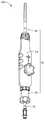
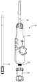
图1是本发明第一实施例提供的导管鞘组件的立体结构示意图。FIG. 1 is a schematic three-dimensional structural diagram of a catheter sheath assembly provided by a first embodiment of the present invention.
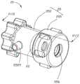
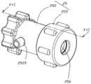
图2是图1中止血阀的立体结构示意图。FIG. 2 is a schematic three-dimensional structure diagram of the hemostatic valve in FIG. 1 .
图3是图2的立体分解示意图。FIG. 3 is a schematic exploded perspective view of FIG. 2 .
图4是图3中的阀芯的另一视角的立体结构示意图。FIG. 4 is a schematic three-dimensional structural diagram of the valve core in FIG. 3 from another perspective.
图5是图4中沿V-V线的剖视图。FIG. 5 is a cross-sectional view taken along line V-V in FIG. 4 .
图6是图4中的阀芯的另一状态的立体结构示意图。FIG. 6 is a schematic three-dimensional structural diagram of the valve core in FIG. 4 in another state.
图7是图6中沿VII-VII线的剖视图。FIG. 7 is a cross-sectional view taken along line VII-VII in FIG. 6 .
图8是图3中的阀芯的另一种结构形式的立体示意图。FIG. 8 is a perspective view of another structural form of the valve core in FIG. 3 .
图9是图8中的阀芯的后视图。FIG. 9 is a rear view of the valve core of FIG. 8 .
图10是图8中沿X-X线的剖视图。FIG. 10 is a cross-sectional view taken along line XX in FIG. 8 .
图11是图3中的阀芯的又一种结构形式的剖视示意图。FIG. 11 is a schematic cross-sectional view of another structural form of the valve core in FIG. 3 .
图12是图3中的阀芯的再一种结构形式的剖视示意图。FIG. 12 is a schematic cross-sectional view of still another structural form of the valve core in FIG. 3 .
图13是图3中的阀壳的另一视角的立体组装示意图。FIG. 13 is a schematic three-dimensional assembly diagram of the valve housing in FIG. 3 from another perspective.
图14是图13中XIV-XIV线的剖视图。FIG. 14 is a cross-sectional view taken along line XIV-XIV in FIG. 13 .
图15是图3中的阀壳与阀盖的立体组装示意图。FIG. 15 is a schematic three-dimensional assembly diagram of the valve housing and the valve cover in FIG. 3 .
图16是图15中沿XVI-XVI线的剖视图。FIG. 16 is a cross-sectional view taken along line XVI-XVI in FIG. 15 .
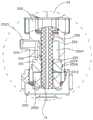
图17是图2中沿XVII-XVII线的剖视图。FIG. 17 is a cross-sectional view taken along line XVII-XVII in FIG. 2 .
图18是图1的导管鞘的立体结构分解示意图。FIG. 18 is a schematic exploded perspective view of the catheter sheath of FIG. 1 .
图19-图20是本发明的导管鞘的使用过程示意图。19-20 are schematic diagrams of the use process of the introducer sheath of the present invention.
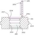
图21是图19中XXI部分的放大图。FIG. 21 is an enlarged view of the portion XXI in FIG. 19 .
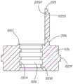
图22是图20中XXII部分的放大图。FIG. 22 is an enlarged view of part XXII in FIG. 20 .
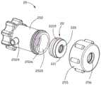
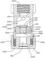
图23是本发明第二实施例提供的止血阀的立体分解结构示意图。23 is a schematic diagram of a three-dimensional exploded structure of the hemostatic valve provided by the second embodiment of the present invention.
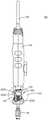
图24是设置有图23中的止血阀的导管鞘组件的结构示意图。FIG. 24 is a schematic structural diagram of the catheter sheath assembly provided with the hemostatic valve in FIG. 23 .
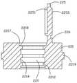
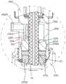
图25是图24中XXV部分的放大图。FIG. 25 is an enlarged view of the portion XXV in FIG. 24 .
具体实施方式Detailed ways
下面将结合本发明实施例中的附图,对本发明实施例中的技术方案进行清楚、完整地描述,显然,所描述的实施例仅仅是本发明一部分实施例,而不是全部的实施例。基于本发明中的实施例,本领域普通技术人员在没有付出创造性劳动前提下所获得的所有其它实施例,都属于本发明保护的范围。The technical solutions in the embodiments of the present invention will be clearly and completely described below with reference to the accompanying drawings in the embodiments of the present invention. Obviously, the described embodiments are only a part of the embodiments of the present invention, but not all of the embodiments. Based on the embodiments of the present invention, all other embodiments obtained by those of ordinary skill in the art without creative efforts shall fall within the protection scope of the present invention.
此外,以下各实施例的说明是参考附加的图示,用以例示本发明可用以实施的特定实施例。本发明中所提到的方向用语,例如,“上”、“下”、“前”、“后”、“左”、“右”、“内”、“外”、“侧面”等,仅是参考附加图式的方向,因此,使用的方向用语是为了更好、更清楚地说明及理解本发明,而不是指示或暗指所指的装置或元件必须具有特定的方位、以特定的方位构造和操作,因此不能理解为对本发明的限制。Furthermore, the following descriptions of the various embodiments refer to the accompanying drawings to illustrate specific embodiments in which the invention may be practiced. Directional terms mentioned in the present invention, such as "up", "down", "front", "rear", "left", "right", "inside", "outside", "side", etc., only Reference is made to the directions of the accompanying drawings, therefore, the directional terms used are for better and clearer description and understanding of the present invention, rather than indicating or implying that the device or element referred to must have a specific orientation, in a specific orientation construction and operation, and therefore should not be construed as limiting the invention.
为了更加清楚地描述止血阀、鞘管及导管鞘组件的结构,本发明所述的限定术语“近端”及“远端”为介入医疗领域惯用术语。具体而言,“远端”表示手术操作过程中远离操作人员的一端,“近端”表示手术操作过程中靠近操作人员的一端。除非另有定义,本发明所使用的所有的技术和科学术语与属于本发明的技术领域的技术人员通常理解的含义相同。本发明在说明书中所使用的惯用术语只是为了描述具体实施例的目的,并不能理解为对本发明的限制。In order to describe the structures of the hemostatic valve, the sheath tube and the catheter sheath assembly more clearly, the defined terms "proximal end" and "distal end" in the present invention are commonly used terms in the field of interventional medicine. Specifically, the "distal end" refers to the end away from the operator during the surgical operation, and the "proximal end" refers to the end close to the operator during the surgical operation. Unless otherwise defined, all technical and scientific terms used herein have the same meaning as commonly understood by one of ordinary skill in the art to which this invention belongs. The conventional terms used in the specification of the present invention are only for the purpose of describing specific embodiments, and should not be construed as limiting the present invention.
请参阅图1、图18至图20,本发明提供一种导管鞘组件100,其包括一鞘管10及一扩张器70,所述鞘管10包括一止血阀20及具有一定轴向长度的一管体50,所述止血阀20设置于所述管体50的近端或邻近近端。进一步地,所述鞘管10还包括设置于所述管体50近端的一手柄54,所述止血阀20可拆卸地连接于所述手柄54的近端,所述扩张器70能活动地依次穿插于所述止血阀20、手柄54及管体50内。所述管体50为可调弯管体或不可调弯管体,所述手柄54能够操控所述管体50,如使所述管体50远端弯曲等。可以理解的是,在其它实施例中,止血阀20可拆卸地连接于所述手柄54的远端,所述扩张器70能活动地依次穿插于手柄54、止血阀20及管体50内。1, 18 to 20, the present invention provides a
请参阅图2至图7,所述止血阀20包括一阀芯22及一阀体25,所述阀芯22设于所述阀体25内。所述阀芯22包括一阀芯主体221及连接于所述阀芯主体221远端的一盖体225,所述阀芯主体221内开设有用于穿插扩张器70或其它诊疗器械的一轴向通孔220,所述盖体225相对所述阀芯主体221打开或自动关闭以相应暴露或封闭所述轴向通孔220。所述扩张器70活动穿装于所述止血阀20的阀芯主体221的轴向通孔220及所述管体50内;所述扩张器70朝远端抵推所述阀芯主体221的盖体225,以解除所述盖体225对轴向通孔220的封闭;当撤退所述扩张器70后,所述盖体225自动复位而封闭所述轴向通孔220。Referring to FIGS. 2 to 7 , the
本发明提供的止血阀20、鞘管10及导管鞘组件100,由于所述止血阀20包括阀芯主体22及盖体225,所述阀芯主体22上开设有用于穿插扩张器70的轴向通孔220,所述盖体225能够相对所述阀芯主体221打开或自动关闭以相应暴露或封闭所述轴向通孔220,类似于舱门的结构。当扩张器70或其它诊疗器械朝远端抵推盖体225,解除盖体225对轴向通孔220的封闭时,扩张器70或其它诊疗器械与所述轴向通孔220之间形成密封;当扩张器70或其它诊疗器械撤退出所述轴向通孔220后,所述盖体225在血压作用下即刻自动复位而封闭所述轴向通孔220形成密封,手术全程防止漏血或气体进入体内,密封效果理想,密封可靠度高,有助于提高手术的安全性和成功率;并且这种类似于舱门结构的止血阀20相比现有的止血阀突破了对扩张器或其它诊疗器械直径的限制,尤其适于配合直径较大的扩张器或其它诊疗器械进行密封。In the
请一并参阅图4至图7,所述阀芯22采用具有弹性且能防水的材料制成,具体地,所述阀芯22可以采用如硅胶、弹性橡胶、弹性塑料等其它具有弹性且能防水的材料制成,优选地,所述阀芯22可以采用如聚苯乙烯弹性体、聚乙烯弹性体、聚氨酯弹性体、硅橡胶或聚异戊二烯橡胶弹性体等材料制成。本实施例中,所述阀芯22采用硅胶制成。所述阀芯22的外形可以是圆柱体、矩形体、腰形体、多边体或不规则体,只需所述阀芯22能密封收容于所述阀体25内即可,本实施例中,所述阀芯22的外形为圆柱体。Please refer to FIG. 4 to FIG. 7 together. The
如图4及图5所示,所述阀芯主体22的远端部设置有所述盖体225,本实施例中,所述盖体225可转动地连接于所述阀芯主体22的远端面邻近所述轴向通孔220处。所述盖体225类似于舱门,在受到朝向远端的推力时,所述盖体225相对于所述阀芯主体221转动而远离所述轴向通孔220,从而使所述轴向通孔220暴露而开通。具体地,所述扩张器70的远端部穿过所述轴向通孔220,并抵推所述盖体225面朝所述轴向通孔220的近端面,使所述盖体225转动而离开所述轴向通孔220,以解除所述盖体225对所述轴向通孔220的封闭,此时,所述盖体225与所述阀芯主体221之间的连接部分发生弹性变形;当扩张器70撤退后朝向远端抵推所述盖体225的推力消失,所述盖体225会在其自身弹性复原的作用下复位而再次关闭所述轴向通孔220,使所述轴向通孔220呈封闭状态,并且血液会向近端压迫盖体225,使得盖体225关闭地更加迅速、可靠,只有盖体225受到朝向远端的推力大于血液对盖体225的压力时,盖体225才会被推开。具体地,当所述扩张器70撤退出所述轴向通孔220而解除对所述盖体225的抵推后,所述盖体225与所述阀芯主体221之间的连接部分弹性复位而驱动所述盖体225复位,以封闭所述轴向通孔220。As shown in FIGS. 4 and 5 , the
所述轴向通孔220沿所述管体50的轴向延伸,且所述轴向通孔220贯穿所述阀芯主体221的近端面及远端面。具体地,所述轴向通孔220沿所述阀芯主体221的轴向方向开设于阀芯主体221的中部位置。所述阀芯主体221在轴向通孔220的内周壁上沿轴向间隔设置有若干内凸缘2212,每一内凸缘2212沿所述轴向通孔220的内周壁周向设置一圈,每相邻近的两个内凸缘2212之间围成一环形槽2214。由于所述内凸缘2212是由具有弹性的防水材料制成,当扩张器70的外周壁挤压每一内凸缘2212时,所述内凸缘2212会弹性变形而收容至对应的环形槽2214内。因此,所述轴向通孔220的内径值决定了能够通过轴向通孔220的鞘芯(鞘芯即扩张器或其它诊疗器械)的最大直径,所述内凸缘2212的内径值决定了内凸缘2212与鞘芯之间的过盈量以及能够通过其中的鞘芯的最小直径。理论上来讲,过盈量越大,密封效果越好,但同时过盈量过大会使得鞘芯在抽送过程中阻力较大。可根据实际要穿入的鞘芯的直径范围来适应性地设计出所述轴向通孔220与内凸缘2212的内径值,从而能使所述止血阀20即使对直径较大的鞘芯也可以起到良好的密封作用,本发明中的止血阀20能适用与24F-15F的大鞘管配合使用。优选地,所述内凸缘2212的内径值较所述轴向通孔220的内径值小5mm-10mm。当有直径大于所述内凸缘2212的内径值的扩张器70插入所述轴向通孔220时,内凸缘2212与扩张器70之间过盈配合能起到密封作用,能防止盖体225打开时血液在扩张器70与所述轴向通孔220的内周面之间渗漏。所述内凸缘2212的数量不限,优选为1-3条;本实施例中,所述内凸缘2212的数量为3条。The axial through
如图6及图7所示,所述阀芯主体221的远端或所述盖体225的近端的其中一者上设有第一止口结构,另一者上设有与所述第一止口结构适配的第二止口结构,所述第一止口结构与所述第二止口结构相互嵌合形成止口,以使所述盖体225紧实、密封地盖合于所述阀芯主体221的轴向通孔220。As shown in FIG. 6 and FIG. 7 , one of the distal end of the
在本实施例中,所述阀芯主体221的远端面上设有与所述轴向通孔220同轴的台阶孔2217作为所述第一止口结构,所述台阶孔2217的孔径大于所述轴向通孔220的孔径并小于所述盖体225的外径,所述盖体225的近端设有与所述台阶孔2217适配的环形凸缘2251作为所述第二止口结构,所述环形凸缘2251嵌入所述台阶孔2217中形成止口。当所述盖体225盖合于所述阀芯主体221上时,所述环形凸缘2251卡入所述台阶孔2217内。可以理解的是,在其它实施例中,也可以将环形凸缘设置在阀芯主体221的远端面上,而将台阶孔设于盖体225的近端。In this embodiment, a stepped
本实施例中,所述台阶孔2217沿所述轴向通孔220的边缘扩展,所述台阶孔2217与所述轴向通孔220连通;由于所述台阶孔2217的内径值大于所述轴向通孔220的内径值,因此,所述阀芯主体221在台阶孔2217与轴向通孔220之间形成一台阶面2218;由于所述台阶孔2217的内径值小于所述盖体225的外径,能防止所述盖体225陷于所述台阶孔2217内。优选地,所述台阶孔2217的内径值约为所述盖体225的直径的三分之二。所述环形凸缘2251的外径等于或略大于所述台阶孔2217的内径值,当所述盖体225盖合于所述阀芯主体221上时,所述环形凸缘2251能紧密地卡入所述台阶孔2217内,且所述环形凸缘2251抵触于所述台阶面2218上,以封闭所述轴向通孔220且能防止所述盖体225陷入所述轴向通孔220内。当所述盖体225盖合于阀芯主体221后,所述盖体225能够有效密封所述轴向通孔220的远端;当所述止血阀20应用在鞘管10及导管鞘组件100中时,所述盖体225关闭所述轴向通孔220后,管体50内的血液压力会进一步朝近端压迫所述盖体225,能够进一步提高止血阀20的密封可靠性,增加密封效果。In this embodiment, the stepped
在其它实施例中,所述第二止口结构也可以是能收容于台阶孔2217内的板体,即所述板体可以是凸设于所述盖体225近端朝向所述轴向通孔220一侧的圆形板,所述圆形板的直径等于或略大于所述台阶孔2217的内径值,所述圆形板能密封地收容于所述台阶孔2217内,且所述圆形板的近端面抵触于所述台阶面2218上。In other embodiments, the second stopper structure may also be a plate body that can be accommodated in the stepped
结合图4至图7以及图16与图17,所述阀芯22的外周面与所述阀体25之间密封接触,优选地,所述阀芯22的外周面与阀体25之间通过定位卡环与定位卡槽的适配进行定位。具体地,阀芯主体221的外周面设置有定位卡环2219,所述阀体25内开设有与所述定位卡环2219适配的定位卡槽2526,当所述阀芯22收容于所述阀体25内时,所述定位卡环2219卡入对应的定位卡槽2526内,以防止所述阀芯主体221在轴向滑动;且所述定位卡环2219与所述定位卡槽2526之间在径向上过盈配合,能防止血液从阀芯22与阀体25之间漏出。所述定位卡环2219的数量不限,优选1或2个。本实施例中,所述定位卡环2219的数量为一个,所述定位卡环2219沿所述阀芯主体221的外周面周向设置连续的一圈。4 to 7 and FIGS. 16 and 17 , the outer peripheral surface of the
如图4所示,所述盖体225上设置有若干加强筋2255,这些加强筋2255用于加强盖体的强度。具体地,盖体225的远端面和/或近端面上设置有若干条加强筋2255,用于加强盖体225的强度,以防止盖体225在较大血压的压力下朝远端翘曲变形导致漏血。进一步地,所述若干加强筋2255可以是分别经过盖体225的圆心均匀地交叉分布,也可以是纵横交错的地分布或其它分布形式。本实施例中,这些加强筋2255设置于所述盖体225的远端面上,这些加强筋2255分别经过盖体225的圆心均匀地交叉分布。As shown in FIG. 4 , the
所述盖体225通过弹性的连接部226连接于所述阀芯主体221,在本实施例中,所述连接部226是连接于所述盖体225与阀芯主体221之间的弹性连接片,所述弹性连接片沿所述轴向通孔220的外围延伸,基本上为弧形的实体。所述连接部226迫使所述盖体225在自然状态下自动封闭所述轴向通孔220,自然状态即指盖体225不受外部作用力的状态,盖体225打开后,所述连接部226弹性复位即带动盖体225自动关闭,加上血液对盖体225的压迫,盖体225会更迅速、更紧密地封闭所述轴向通孔220。如图5所示,当所述盖体225封闭所述轴向通孔220时,所述连接部226的横截面呈L形或圆弧形。本实施例中,所述阀芯主体221、盖体225及连接部226由具有弹性的防水材料一体成型制成。The
请一并参阅图8至图10,本发明的阀芯的另一种结构形式与阀芯第一实施例的结构相似,不同之处在于:在另一种结构形式的阀芯中,盖体225与所述阀芯主体221之间的连接部226a是若干弹性连接杆,这些弹性连接杆能弹性复位而自动驱动盖体225封闭所述阀芯主体221的轴向通孔220。若干所述弹性连接杆相互间隔排列,选优的,这些连弹性接杆沿所述轴向通孔220的外围相互间隔排列。Please refer to FIG. 8 to FIG. 10 together, another structural form of the valve core of the present invention is similar to the structure of the first embodiment of the valve core, the difference is: in the valve core of the other structural form, the cover body The connecting
所述连接部226a可以作为独立的部件连接于所述盖体225与阀芯主体221之间;所述连接部226a也可以由具有弹性的防水材料与阀芯主体221及盖体225一体成型制成。The connecting
请参阅图11,本发明中阀芯的又一种结构形式与第一实施例的结构相似,不同之处在于:在又一种结构形式的阀芯中,阀芯主体221的远端面凸设有环形凸缘2211,所述环形凸缘2211作为第一止口结构;所述盖体225上开设有适配所述环形凸缘2211的定位环形槽2257作为第二止口结构,当所述盖体225封闭所述轴向通孔220时,所述环形凸缘2211卡接于所述定位环形槽2257内。Referring to FIG. 11 , another structural form of the valve core of the present invention is similar to that of the first embodiment, except that in the valve core of the other structural form, the distal end surface of the
在阀芯的所述又一种结构形式中,所述环形凸缘2211是凸设于所述阀芯主体221的远端面,并沿所述轴向通孔220的边缘环绕一圈,定位环形槽2257为开设于所述盖体225的近端面上。当所述盖体225封闭轴向通孔220时,环形凸缘2211卡人于所述定位环形槽2257内。In the other structural form of the valve core, the
请参阅图12,本发明中阀芯的再一种结构形式与第一实施例的结构相似,不同之处在于:在所述再一种结构形式的阀芯中,阀芯主体221的外周面沿其周向开设有至少一定位卡槽2213,所述阀体25内设置有与所述定位卡槽2213对应的定位卡环,当所述阀芯22收容于所述阀体25内时,所述阀体25的定位卡环卡入对应的定位卡槽2213内,以防止所述阀芯主体221在轴向滑动;所述定位卡环与所述定位卡槽2213之间在径向上过盈配合,能防止血液从阀芯22与阀体25之间漏出。所述定位卡槽2213的数量不限,优选1或2个。本实施例中,所述定位卡槽2213沿所述阀芯主体221的外周面周向设置连续的一圈。Referring to FIG. 12 , another structural form of the valve core in the present invention is similar to the structure of the first embodiment, the difference is that: in the valve core of the further structural form, the outer peripheral surface of the valve core
请一并参阅图13至图16,所述阀体25可以由高分子材料或金属材料制成,优选的,本实施例中的阀体25由透明PC材料制成。阀体25包括一阀壳252及连接于所述阀壳252的一阀盖255。具体地,所述阀盖255可拆卸地连接于所述阀壳252的近端。所述阀体25沿所述管体50的轴向开设有贯穿所述阀壳252及所述阀盖255的空腔256。所述阀壳252基本呈管状体,所述阀壳252的外形可以是圆柱形的管状体、矩形的管状体或多边形的管状体或其它形状的管状体。本实施例中,所述阀壳252为圆柱形的管状体,所述空腔256轴向地贯穿所述阀壳252的远端面及近端面。所述阀壳252内开设有与所述空腔256同轴心线的收容空间2520,所述收容空间2520的内径值大于所述空腔256的内径值,所述收容空间2520用于收容所述阀体22。Please refer to FIG. 13 to FIG. 16 together, the
具体地,所述收容空间2520包括定位段2522及轴向连通所述定位段2522的避位段2524,所述定位段2522用于定位所述阀芯主体221,所述避位段2524用于为阀芯22的盖体225的打开提供空间。具体地,所述定位段2522与避位段2524同轴心线,所述定位段2522及避位段2524自所述阀芯主体221的近端至远端依次设置,即,所述定位段2522位于所述阀壳252的近端,且所述定位段2522贯穿至所述阀壳252的近端面,所述避位段2524位于所述定位段2522的远端。所述定位段2522的内径值等于或略小于所述阀芯主体221的外径,从而使所述阀芯主体221的外周面密封贴合于所述收容空间2520的定位段2522的内周面。所述定位段2522的内径值大于所述避位段2524的内径值,使所述阀壳252在所述定位段2522与所述避位段2524之间形成一定位面2535,当所述阀芯主体221收容于所述定位段2522内时,所述阀芯主体221的远端能抵触于所述定位面2535上。所述避位段2524的内径值大于所述阀芯22的盖体225的外径,且所述避位段2524在轴向方向的延伸长度大于所述盖体225的外径,因此,在所述盖体225在打开时,所述盖体225能完全收容纳于所述避位段2524内。Specifically, the
所述阀体22的外周面与所述收容空间2520的定位段2522的内周面之间通过定位卡环与定位卡槽的卡接进行定位。具体地,本实施例中,所述阀芯主体221的收容空间2520的定位段2522的内壁面上设有环形的至少一定位卡槽2526,至少一所述定位卡槽2526沿所述定位段2522的周向设置一圈,所述定位卡槽2526的内径值大于所述定位段2522的内径值,所述定位卡槽2526用于卡接所述阀芯主体221的定位卡环2219,从而能定位所述阀芯22在阀壳252内,不能沿轴向移动。进一步地,所述定位卡槽2526的内径值略小于所述阀芯主体221的定位卡环2219的外径,所述定位卡槽2526在轴向方向上的延伸长度大于阀芯主体221的定位卡环2219在轴向方向上的延伸长度。当所述阀体22收容于所述收容空间2520时内,所述阀芯主体221的定位卡环2219与所述定位卡槽2526在径向上过盈配合,能防止血液从阀体22的外周面与阀壳252内周面之间漏出;另外,所述定位卡环2219与定位卡槽2526在轴向方向上有变形空间,当挤压所述阀芯主体221时,所述定位卡环2219能填充至所述变形空间内,从而起到在径向上密封阀芯22与阀体25的作用。The positioning between the outer peripheral surface of the
可以理解的是,在其它实施列中,阀壳252的收容空间2520的定位段2522的内壁面上凸设有环形的至少一定位卡环,至少一所述定位卡环沿所述定位段2522的周向设置一圈,所述定位卡环的内径值小于所述定位段2522的内径值,所述定位卡环用于卡接于如图12所示的阀芯主体221的定位卡槽2213内,从而防止阀芯22在轴向上移动。具体地,定位卡环的内径值略小于所述定位卡槽2213的内径值,从而能使所述定位卡环与所述定位卡槽2213在径向上过盈配合,以防止血液从阀体22的外周面与阀壳252内周面之间漏出。It can be understood that, in other embodiments, at least one annular positioning snap ring is protruded on the inner wall surface of the
在一实施例中,所述阀壳252的远端于所述空腔256的内壁面上开设有内螺纹2527,所述内螺纹2527用于将所述阀体25螺接于所述手柄54上;所述阀壳252的远端的外周面上设置有若干防滑条,方便握持。所述阀壳252的近端的外周面设置有外螺纹2528,所述外螺纹2528用于连接所述阀盖255。所述阀壳252上还开设有沿径向贯穿至空腔256内的通孔2529,具体地,所述通孔2529贯穿至所述收容空间2520的避位段2524,所述通孔2529用于连接设于阀体25外部的三通阀。In one embodiment, the distal end of the
所述阀盖255的外形可以是圆柱形、矩形或多边形或其它形状。在一具体实施例中,所述阀盖255为圆柱形。所述阀盖255包括圆形的近端板2552、自所述近端板2552的四周边缘朝远端延伸的环形的侧板2553,以及凸设于所述近端板2552中部朝远端凸出的挤压块2555。所述挤压块2555与所述侧板2553之间具有间隙,所述侧板2553的内周面上开设有内螺纹2556,所述内螺纹2556与设于所述阀壳252近端的外螺纹2528配合,以方便将所述阀盖255连接于所述阀壳252的近端。所述空腔256轴向地贯穿所述挤压块2555及所述近端板2552。The shape of the
请参阅图2、图3及图17,组装所述止血阀20时,将所述阀芯22设置有盖体225的远端自所述阀壳252的近端装入所述收容空间2520内,直至所述阀芯22的阀芯主体221收容于定位段2522内,所述盖体225收容于所述避位段2524内。此时,所述定位卡环2219卡接于定位卡槽2526内,所述阀芯主体221的外周面与所述定位段2522的内周面紧密贴合,所述定位卡环2219与所述定位卡槽2526过盈配合,所述盖体225封闭所述阀芯主体221的轴向通孔220,且所述环形凸缘2251卡入台阶孔2217内,从而阀芯22与阀壳252之间密封连接。再将阀盖255螺接于所述阀壳252的近端。Referring to FIGS. 2 , 3 and 17 , when assembling the
请一并参阅图18至图22,以心脏房间隔穿刺为例,所述导管鞘组件100的实用过程为:先将止血阀20的远端连接于所述鞘管10的手柄54的近端,具体地,所述手柄54的近端设有带外螺纹的连接管55,所述止血阀20的阀壳252远端的内螺纹2527螺接于所述连接管55的外螺纹上。再行血管穿刺术,将鞘管10的管体50的远端输送至邻近心脏房间隔处,此时,所述止血阀20的盖体225封闭所述轴向通孔220,在血压的作用下,盖体225紧密贴合在阀芯主体221上以阻止血液渗漏及气体进入体内;再向所述鞘管10内插入扩张器70,具体地,当所述扩张器70的远端抵推所述阀芯22的盖体225的近端面时,使所述盖体225脱离与所述阀芯主体221的贴合,直至扩张器70的远端将盖体225完全打开,所述盖体255收容于收容空间2520的避位段2524内,所述盖体225与所述阀芯主体221之间的连接部226发生弹性变形;扩张器70可以继续往远端推送到达指定的位置,在这个过程中,所述轴向通孔220内的内凸缘2212与扩张器70过盈配合以进行密封,防止血液渗漏及气体进入体内。然后向所述扩张器70内插入穿刺针,使所述穿刺针对所述心脏房间隔做穿剌;穿剌完成后,将所述穿刺针收入至所述扩张器70内,并随所述扩张器70一起撤出,在扩张器70撤出的过程中,所述扩张器70的远端退出到所述阀芯主体221的轴向通孔220内时,所述扩张器70解除对所述盖体225的抵推,所述盖体225与所述阀芯主体221之间的连接部226弹性复位力及血压压迫的共同作用使盖体225瞬间恢复到初始位置与阀芯主体221贴合,即盖体225封闭所述阀芯主体221的轴向通孔220进行密封,且环形凸缘2251卡入台阶孔2217内,所以在扩张器70向后撤出的过程中也不会有血液渗漏及气体进入体内,该止血阀20在手术全程中都能起到可靠、良好的密封作用。本发明的止血阀20对于外径较大的扩张器70,适应性的设定所述盖体225、轴向通孔220及内凸缘2212的相关尺寸即能确保良好的密封效果,突破了现有的止血阀对扩张器或其它诊疗器械直径的限制,从而尤其适于配合直径较大的扩张器70或其它诊疗器械进行密封。另外,设置可以开合的盖体225及在阀芯主体221的轴向通孔220的内设置的若干内凸缘2212,能够使扩张器70在推送时受到的阻滞力较小。Please refer to FIG. 18 to FIG. 22 together. Taking atrial septal puncture as an example, the practical process of the
在心脏房间隔穿刺后,若需输送其它诊疗器械,可以利用所述管体50的内腔及止血阀20的轴向通孔220进行输送。After the atrial septal puncture, if other medical instruments need to be delivered, the inner cavity of the
本发明的止血阀20能够全程可靠密封,密封效果优良,杜绝发生漏血及气体进入体内的风险,提高手术的安全性和成功率,且仅需推送或后撤扩张器70或其它诊疗器械,无需对止血阀20做额外操作,操作简单,使用方便。The
在其它实施例中,所述止血阀20与所述鞘管10之间还可以通过卡接、胶接或焊接等方式连接,保证止血阀20的空腔256连通所述鞘管10即可。In other embodiments, the
请一并参阅图23至25,本发明的第二实施例提供的导管鞘组件的结构与第一实施例的结构相似,不同之处在于:在第二实施例中,所述止血阀20还包括弹性垫片27,所述弹性垫片27被夹持于所述阀芯主体22与阀盖255之间,沿轴向移动所述阀盖255能挤压弹性垫片27变形。具体地,所述弹性垫片27轴向开设有连通所述阀芯主体22的轴向通孔220的贯穿孔272,所述贯穿孔272的内径值等于或略小于所述扩张器70的外径,从而使所述弹性垫片27的贯穿孔272的内周面与所述扩张器70的外周面之间过盈配合,从而实现扩张器70穿入时的密封。通过驱使所述阀盖255沿轴向向远端或近端移动使所述阀盖225压紧或松开所述弹性垫片27,以使得所述弹性垫片27变形来控制所述弹性垫片27内的贯穿孔272的孔径缩小或扩大。具体地,旋紧或旋松所述阀盖255,使阀盖255的挤压块2555压紧或松开所述弹性垫片27,能使所述弹性垫片27变形,来控制所述弹性垫片27的贯穿孔272的内径值的缩小或扩大,以适应外径不同尺寸的扩张器70。Please refer to FIGS. 23 to 25 together. The structure of the catheter sheath assembly provided by the second embodiment of the present invention is similar to that of the first embodiment, except that in the second embodiment, the
所述弹性垫片27可以是圆柱形、多边形等,优选地,所述弹性垫片27为圆柱形。所述弹性垫片27由硅胶、弹性橡胶、弹性塑料等材料制成,本实施例中,所述弹性垫片27由硅胶制成。The
本实施列中,由于止血阀20设置有盖体225,在扩张器70撤出后,所述盖体225自动封闭所述轴向通孔220,无需再旋紧所述阀盖255使弹性垫片27的贯穿孔272的内径值缩小为0来进行密封。In this embodiment, since the
本实施例中,可以省略掉所述阀芯主体22的轴向通孔220的内周壁上设置的内凸缘2212。In this embodiment, the
以上是本发明实施例的实施方式,应当指出,对于本技术领域的普通技术人员来说,在不脱离本发明实施例原理的前提下,还可以做出若干改进和润饰,这些改进和润饰也视为本发明的保护范围。The above are the implementations of the embodiments of the present invention. It should be pointed out that for those of ordinary skill in the art, without departing from the principles of the embodiments of the present invention, several improvements and modifications can also be made. These improvements and modifications are also It is regarded as the protection scope of the present invention.
Claims (16)
Translated fromChinesePriority Applications (4)
| Application Number | Priority Date | Filing Date | Title |
|---|---|---|---|
| CN201811585662.4ACN111346294B (en) | 2018-12-24 | 2018-12-24 | Hemostatic valve, sheath and catheter sheath assembly |
| PCT/CN2019/099367WO2020134092A1 (en) | 2018-12-24 | 2019-08-06 | Hemostatic valve, sheath, and catheter sheath assembly |
| EP19906112.8AEP3903873A4 (en) | 2018-12-24 | 2019-08-06 | Hemostatic valve, sheath, and catheter sheath assembly |
| US17/354,559US20210316128A1 (en) | 2018-12-24 | 2021-06-22 | Hemostatic valve, sheath, and catheter sheath assembly |
Applications Claiming Priority (1)
| Application Number | Priority Date | Filing Date | Title |
|---|---|---|---|
| CN201811585662.4ACN111346294B (en) | 2018-12-24 | 2018-12-24 | Hemostatic valve, sheath and catheter sheath assembly |
Publications (2)
| Publication Number | Publication Date |
|---|---|
| CN111346294Atrue CN111346294A (en) | 2020-06-30 |
| CN111346294B CN111346294B (en) | 2025-10-03 |
Family
ID=71188525
Family Applications (1)
| Application Number | Title | Priority Date | Filing Date |
|---|---|---|---|
| CN201811585662.4AActiveCN111346294B (en) | 2018-12-24 | 2018-12-24 | Hemostatic valve, sheath and catheter sheath assembly |
Country Status (1)
| Country | Link |
|---|---|
| CN (1) | CN111346294B (en) |
Cited By (5)
| Publication number | Priority date | Publication date | Assignee | Title |
|---|---|---|---|---|
| CN114587443A (en)* | 2022-03-10 | 2022-06-07 | 安骏生物医疗科技(苏州)有限公司 | Hydraulic control adjustable bending sheath |
| CN114588475A (en)* | 2022-02-24 | 2022-06-07 | 浙江巴泰医疗科技有限公司 | medical sheath device |
| CN116020047A (en)* | 2021-10-25 | 2023-04-28 | 杭州德晋医疗科技有限公司 | hemostasis valve |
| CN117297730A (en)* | 2023-11-16 | 2023-12-29 | 上海以心医疗器械有限公司 | Hemostatic valve, valve body assembly and sheath tube suitable for interventional conveying system |
| WO2024125223A1 (en)* | 2022-12-12 | 2024-06-20 | 先健科技(深圳)有限公司 | Delivery sheath |
Citations (9)
| Publication number | Priority date | Publication date | Assignee | Title |
|---|---|---|---|---|
| US4430081A (en)* | 1981-01-06 | 1984-02-07 | Cook, Inc. | Hemostasis sheath |
| US5057084A (en)* | 1990-03-01 | 1991-10-15 | The Regents Of The University Of Michigan | Implantable infusion device |
| US5059186A (en)* | 1988-03-07 | 1991-10-22 | Vitaphore Corporation | Percutaneous access device |
| US20040260243A1 (en)* | 2003-06-19 | 2004-12-23 | Rickerd Claude L. | Connection assembly for use with splittable sheath |
| US20070293845A1 (en)* | 2006-03-20 | 2007-12-20 | Leeflang Stephen A | Slittable or removable valves and apparatus and methods for making and using them |
| CN201564982U (en)* | 2010-01-12 | 2010-09-01 | 刘爱国 | Elastic end socket for pipe tie-in |
| CN204840602U (en)* | 2015-05-20 | 2015-12-09 | 湖南埃普特医疗器械有限公司 | Tube sheath is led to adjustable valve |
| CN105962990A (en)* | 2016-06-08 | 2016-09-28 | 深圳市科奕顿生物医疗科技有限公司 | An interventional medical device delivery system |
| CN209967413U (en)* | 2018-12-24 | 2020-01-21 | 杭州唯强医疗科技有限公司 | Hemostatic Valves, Sheaths and Introducer Sheath Assemblies |
- 2018
- 2018-12-24CNCN201811585662.4Apatent/CN111346294B/enactiveActive
Patent Citations (9)
| Publication number | Priority date | Publication date | Assignee | Title |
|---|---|---|---|---|
| US4430081A (en)* | 1981-01-06 | 1984-02-07 | Cook, Inc. | Hemostasis sheath |
| US5059186A (en)* | 1988-03-07 | 1991-10-22 | Vitaphore Corporation | Percutaneous access device |
| US5057084A (en)* | 1990-03-01 | 1991-10-15 | The Regents Of The University Of Michigan | Implantable infusion device |
| US20040260243A1 (en)* | 2003-06-19 | 2004-12-23 | Rickerd Claude L. | Connection assembly for use with splittable sheath |
| US20070293845A1 (en)* | 2006-03-20 | 2007-12-20 | Leeflang Stephen A | Slittable or removable valves and apparatus and methods for making and using them |
| CN201564982U (en)* | 2010-01-12 | 2010-09-01 | 刘爱国 | Elastic end socket for pipe tie-in |
| CN204840602U (en)* | 2015-05-20 | 2015-12-09 | 湖南埃普特医疗器械有限公司 | Tube sheath is led to adjustable valve |
| CN105962990A (en)* | 2016-06-08 | 2016-09-28 | 深圳市科奕顿生物医疗科技有限公司 | An interventional medical device delivery system |
| CN209967413U (en)* | 2018-12-24 | 2020-01-21 | 杭州唯强医疗科技有限公司 | Hemostatic Valves, Sheaths and Introducer Sheath Assemblies |
Cited By (5)
| Publication number | Priority date | Publication date | Assignee | Title |
|---|---|---|---|---|
| CN116020047A (en)* | 2021-10-25 | 2023-04-28 | 杭州德晋医疗科技有限公司 | hemostasis valve |
| CN114588475A (en)* | 2022-02-24 | 2022-06-07 | 浙江巴泰医疗科技有限公司 | medical sheath device |
| CN114587443A (en)* | 2022-03-10 | 2022-06-07 | 安骏生物医疗科技(苏州)有限公司 | Hydraulic control adjustable bending sheath |
| WO2024125223A1 (en)* | 2022-12-12 | 2024-06-20 | 先健科技(深圳)有限公司 | Delivery sheath |
| CN117297730A (en)* | 2023-11-16 | 2023-12-29 | 上海以心医疗器械有限公司 | Hemostatic valve, valve body assembly and sheath tube suitable for interventional conveying system |
Also Published As
| Publication number | Publication date |
|---|---|
| CN111346294B (en) | 2025-10-03 |
Similar Documents
| Publication | Publication Date | Title |
|---|---|---|
| CN111346294A (en) | Hemostatic valve, sheath tube and catheter sheath assembly | |
| EP1478416B1 (en) | Haemostasis catheter | |
| CA2500475C (en) | System and method for delivering hemostasis promoting material to a blood vessel puncture site by fluid pressure | |
| JP2024087012A (en) | Introducer sheath | |
| US8123727B2 (en) | Flush entrance hemostasis valve with unobstructed passageway | |
| US4966587A (en) | Medical intromission kit | |
| CA2351443C (en) | Valved connector with closure operated by axial movement of the valve | |
| US7029489B1 (en) | System and method for delivering hemostasis promoting material to a blood vessel puncture site | |
| US7037322B1 (en) | System and method for delivering hemostasis promoting material to a blood vessel puncture with a staging tube | |
| JP5524826B2 (en) | Introducer adapter | |
| JPH02189163A (en) | hemostasis valve | |
| WO2013005607A1 (en) | Introducer sheath | |
| EP1691864B1 (en) | Pledget valve delivery system | |
| JPH0433238B2 (en) | ||
| MX2010012204A (en) | Push-button blood control. | |
| CN209967413U (en) | Hemostatic Valves, Sheaths and Introducer Sheath Assemblies | |
| US10085730B2 (en) | Hemostatic device and its methods of use | |
| US20210316128A1 (en) | Hemostatic valve, sheath, and catheter sheath assembly | |
| WO2024139967A1 (en) | Delivery device and delivery system | |
| WO1991010459A1 (en) | Hemostasis valve introducer | |
| JP3611888B2 (en) | Medical insertion tool | |
| EP4154937A1 (en) | Floating hemostasis valve | |
| WO1995021642A1 (en) | Hemostasis cannula | |
| WO2024227400A1 (en) | Delivery device and delivery system | |
| CN119565015A (en) | Sealing valve and conveying system |
Legal Events
| Date | Code | Title | Description |
|---|---|---|---|
| PB01 | Publication | ||
| PB01 | Publication | ||
| SE01 | Entry into force of request for substantive examination | ||
| SE01 | Entry into force of request for substantive examination | ||
| GR01 | Patent grant |