CN111345926A - Conveying device and conveying system - Google Patents
Conveying device and conveying systemDownload PDFInfo
- Publication number
- CN111345926A CN111345926ACN201811564443.8ACN201811564443ACN111345926ACN 111345926 ACN111345926 ACN 111345926ACN 201811564443 ACN201811564443 ACN 201811564443ACN 111345926 ACN111345926 ACN 111345926A
- Authority
- CN
- China
- Prior art keywords
- casing
- groove
- circumferential groove
- limiting member
- axial groove
- Prior art date
- Legal status (The legal status is an assumption and is not a legal conclusion. Google has not performed a legal analysis and makes no representation as to the accuracy of the status listed.)
- Granted
Links
Images


Classifications
- A—HUMAN NECESSITIES
- A61—MEDICAL OR VETERINARY SCIENCE; HYGIENE
- A61F—FILTERS IMPLANTABLE INTO BLOOD VESSELS; PROSTHESES; DEVICES PROVIDING PATENCY TO, OR PREVENTING COLLAPSING OF, TUBULAR STRUCTURES OF THE BODY, e.g. STENTS; ORTHOPAEDIC, NURSING OR CONTRACEPTIVE DEVICES; FOMENTATION; TREATMENT OR PROTECTION OF EYES OR EARS; BANDAGES, DRESSINGS OR ABSORBENT PADS; FIRST-AID KITS
- A61F2/00—Filters implantable into blood vessels; Prostheses, i.e. artificial substitutes or replacements for parts of the body; Appliances for connecting them with the body; Devices providing patency to, or preventing collapsing of, tubular structures of the body, e.g. stents
- A61F2/95—Instruments specially adapted for placement or removal of stents or stent-grafts
- A—HUMAN NECESSITIES
- A61—MEDICAL OR VETERINARY SCIENCE; HYGIENE
- A61B—DIAGNOSIS; SURGERY; IDENTIFICATION
- A61B17/00—Surgical instruments, devices or methods
- A61B17/34—Trocars; Puncturing needles
- A—HUMAN NECESSITIES
- A61—MEDICAL OR VETERINARY SCIENCE; HYGIENE
- A61F—FILTERS IMPLANTABLE INTO BLOOD VESSELS; PROSTHESES; DEVICES PROVIDING PATENCY TO, OR PREVENTING COLLAPSING OF, TUBULAR STRUCTURES OF THE BODY, e.g. STENTS; ORTHOPAEDIC, NURSING OR CONTRACEPTIVE DEVICES; FOMENTATION; TREATMENT OR PROTECTION OF EYES OR EARS; BANDAGES, DRESSINGS OR ABSORBENT PADS; FIRST-AID KITS
- A61F2/00—Filters implantable into blood vessels; Prostheses, i.e. artificial substitutes or replacements for parts of the body; Appliances for connecting them with the body; Devices providing patency to, or preventing collapsing of, tubular structures of the body, e.g. stents
- A61F2/02—Prostheses implantable into the body
- A61F2/24—Heart valves ; Vascular valves, e.g. venous valves; Heart implants, e.g. passive devices for improving the function of the native valve or the heart muscle; Transmyocardial revascularisation [TMR] devices; Valves implantable in the body
- A—HUMAN NECESSITIES
- A61—MEDICAL OR VETERINARY SCIENCE; HYGIENE
- A61F—FILTERS IMPLANTABLE INTO BLOOD VESSELS; PROSTHESES; DEVICES PROVIDING PATENCY TO, OR PREVENTING COLLAPSING OF, TUBULAR STRUCTURES OF THE BODY, e.g. STENTS; ORTHOPAEDIC, NURSING OR CONTRACEPTIVE DEVICES; FOMENTATION; TREATMENT OR PROTECTION OF EYES OR EARS; BANDAGES, DRESSINGS OR ABSORBENT PADS; FIRST-AID KITS
- A61F2/00—Filters implantable into blood vessels; Prostheses, i.e. artificial substitutes or replacements for parts of the body; Appliances for connecting them with the body; Devices providing patency to, or preventing collapsing of, tubular structures of the body, e.g. stents
- A61F2/95—Instruments specially adapted for placement or removal of stents or stent-grafts
- A61F2/962—Instruments specially adapted for placement or removal of stents or stent-grafts having an outer sleeve
- A61F2/966—Instruments specially adapted for placement or removal of stents or stent-grafts having an outer sleeve with relative longitudinal movement between outer sleeve and prosthesis, e.g. using a push rod
Landscapes
- Health & Medical Sciences (AREA)
- Engineering & Computer Science (AREA)
- Biomedical Technology (AREA)
- Life Sciences & Earth Sciences (AREA)
- Veterinary Medicine (AREA)
- General Health & Medical Sciences (AREA)
- Heart & Thoracic Surgery (AREA)
- Cardiology (AREA)
- Public Health (AREA)
- Animal Behavior & Ethology (AREA)
- Oral & Maxillofacial Surgery (AREA)
- Transplantation (AREA)
- Vascular Medicine (AREA)
- Surgery (AREA)
- Pathology (AREA)
- Nuclear Medicine, Radiotherapy & Molecular Imaging (AREA)
- Medical Informatics (AREA)
- Molecular Biology (AREA)
- Prostheses (AREA)
Abstract
Description
Translated fromChinese技术领域technical field
本发明涉及介入医疗领域,具体涉及一种输送装置及输送系统。The invention relates to the field of interventional medicine, in particular to a delivery device and a delivery system.
背景技术Background technique
人体的心脏分为四个腔室,每个腔室都有各自的“出口”,共有四个瓣膜(二尖瓣、主动脉瓣、肺动脉瓣和三尖瓣),它们确保由心脏泵送的血液能在心血管系统中按照指定的方向流过。二尖瓣位于左心房和左心室之间,正常的二尖瓣保证血液循环由左心房向左心室方向流动,且可防止血液从心脏的左心室向左心房回流。各种心脏疾病或退行性病变的发生,可能导致二尖瓣功能障碍,使得二尖瓣变得异常缩窄或扩张。二尖瓣功能的缺失损伤,会影响心脏的正常工作,致使人逐渐衰弱或危及生命。The human heart is divided into four chambers, each with its own "outlet", and a total of four valves (the mitral, aortic, pulmonary, and tricuspid valves) that ensure the Blood flows in a specified direction in the cardiovascular system. The mitral valve is located between the left atrium and the left ventricle. The normal mitral valve ensures blood circulation from the left atrium to the left ventricle and prevents the blood from flowing back from the left ventricle of the heart to the left atrium. The occurrence of various heart diseases or degenerative diseases may lead to mitral valve dysfunction, causing the mitral valve to become abnormally narrowed or dilated. The loss of mitral valve function can affect the normal work of the heart, causing people to gradually become debilitating or life-threatening.
针对二尖瓣功能的缺失,目前已有多种治疗二尖瓣功能障碍的方法,如传统的瓣膜置换手术,被认为是“开放心脏”手术。简而言之,手术时需要打开胸腔,用心肺机启动体外循环,打开心脏,切除和更换患者的病变二尖瓣,但由于体外循坏的操作复杂和老年患者的耐受性差,这种手术往往有较高的死亡风险。近年来,通过介入手段治疗二尖瓣功能障碍的方法逐渐被人们所关注,并开发了用于递送置换二尖瓣组装件的创伤较小的经导管技术。在此类技术中,自膨式假体瓣膜一般以卷曲状态安装在柔性导管的末端并经患者的血管推进,直至该假体瓣膜抵达植入部位。继而假体瓣膜在有缺陷的天然二尖瓣膜的部位处扩张至其功能尺寸,替代病变瓣膜。For the loss of mitral valve function, there are currently a variety of methods to treat mitral valve dysfunction, such as traditional valve replacement surgery, which is considered as "open heart" surgery. In short, during the operation, the chest cavity needs to be opened, cardiopulmonary bypass is activated with a heart-lung machine, the heart is opened, and the patient's diseased mitral valve is removed and replaced. However, due to the complicated operation of cardiopulmonary bypass and the poor tolerance of elderly patients, this surgery Often has a higher risk of death. In recent years, there has been increasing interest in the treatment of mitral valve dysfunction by interventional means, and less invasive transcatheter techniques have been developed for the delivery of replacement mitral valve assemblies. In such techniques, a self-expanding prosthetic valve is typically mounted on the tip of a flexible catheter in a crimped state and advanced through the patient's blood vessel until the prosthetic valve reaches the implantation site. The prosthetic valve is then expanded to its functional size at the site of the defective native mitral valve, replacing the diseased valve.
虽然经导管介入技术置换天然二尖瓣膜是治疗二尖瓣功能不全的有效方法,但由于二尖瓣复合体的解剖结构较复杂、心室收缩产生的腔内压力较大,人工瓣膜的释放位置可能不理想或在血流冲击下释放发生移位。若此时出现瓣膜移位,则会因瓣周漏导致手术失败,产生严重不良后果。因此期望能有一种输送装置,其在瓣膜解脱前还能够确认瓣膜与心房壁是否紧密贴合,从而减少因瓣膜位置不准确或贴合不紧而发生瓣周漏的风险。Although transcatheter interventional technique to replace the natural mitral valve is an effective method for the treatment of mitral valve insufficiency, due to the complex anatomical structure of the mitral valve complex and the large intraluminal pressure generated by ventricular contraction, the release position of the artificial valve may be Unsatisfactory or the release occurs under the shock of blood flow. If the valve is displaced at this time, the operation will fail due to paravalvular leakage, resulting in serious adverse consequences. Therefore, it is desirable to have a delivery device that can also confirm the tight fit of the valve with the atrial wall before the valve is released, thereby reducing the risk of paravalvular leakage due to inaccurate valve position or loose fit.
发明内容SUMMARY OF THE INVENTION
本发明提供了一种输送装置,包括导管组件和控制组件,所述控制组件设于所述导管组件近端,所述控制组件包括第一控制机构,所述第一控制机构包括中空的壳体和限位单元,所述限位单元包括限位件和中空的收容件,所述收容件设于所述壳体内;所述收容件的外表面设有轴向凹槽和周向凹槽,所述限位件部分穿过所述壳体后收容于所述轴向凹槽或周向凹槽内,使得所述壳体可轴向移动或周向转动,所述壳体再带动且所述限位件轴向移动或周向转动。The present invention provides a delivery device, comprising a catheter assembly and a control assembly, the control assembly is provided at the proximal end of the catheter assembly, the control assembly includes a first control mechanism, and the first control mechanism includes a hollow housing and a limiting unit, the limiting unit includes a limiting member and a hollow receiving member, the receiving member is arranged in the housing; the outer surface of the receiving member is provided with an axial groove and a circumferential groove, the The limiting member partially passes through the casing and is accommodated in the axial groove or the circumferential groove, so that the casing can move axially or rotate circumferentially, and the casing is then driven and the limiting member Axial movement or circumferential rotation.
在一实施例中,所述轴向凹槽与所述周向凹槽均由所述收容件的外表面径向内凹形成,且所述周向凹槽为贯通槽。In one embodiment, both the axial groove and the circumferential groove are formed by radially inward concave on the outer surface of the receiving member, and the circumferential groove is a through groove.
在一实施例中,所述轴向凹槽与所述周向凹槽交叉设置,且交叉处设有切口所述切口用于允许所述限位件的位置在所述轴向凹槽与所述周向凹槽之间转换。In one embodiment, the axial groove and the circumferential groove are arranged intersecting, and a cutout is provided at the intersection. The cutout is used to allow the position of the limiting member to be between the axial groove and the circumferential groove. switch between slots.
在一实施例中,所述交叉处设有两个切口和第二圆角,且所述两个切口和两个第二圆角分别设于所述交叉处的两条对角线上,所述两个切口之间的距离大于所述两个第二圆角之间的距离。In one embodiment, the intersection is provided with two incisions and second rounded corners, and the two incisions and the two second rounded corners are respectively set on two diagonal lines of the intersection, so The distance between the two cutouts is greater than the distance between the two second rounded corners.
在一实施例中,所述壳体侧壁设有通孔,所述通孔与所述壳体外表面之间形成两个凸台;所述限位件包括转动体,所述转动体夹设于所述两个凸台之间。In one embodiment, the side wall of the casing is provided with a through hole, and two bosses are formed between the through hole and the outer surface of the casing; the limiting member includes a rotating body, which is sandwiched by the rotating body. between the two bosses.
在一实施例中,所述周向凹槽与所述轴向凹槽不连通;所述限位件包括按压板和设于所述按压板内侧的两个轴向相互间隔开的止挡体;两个所述止挡体中,一个所述止挡体收容于所述轴向凹槽或另一个所述止挡体收容于所述周向凹槽。In one embodiment, the circumferential groove is not communicated with the axial groove; the limiting member includes a pressing plate and two axially spaced stop bodies disposed on the inner side of the pressing plate; two Among the stopper bodies, one stopper body is accommodated in the axial groove or the other stopper body is accommodated in the circumferential groove.
在一实施例中,所述限位件两侧通过转轴与所述壳体相连。In one embodiment, both sides of the limiting member are connected to the housing through a rotating shaft.
在一实施例中,所述导管组件包括内管,所述内管与所述壳体相连且所述内管相对所述壳体静止。In one embodiment, the conduit assembly includes an inner tube that is connected to the housing and that is stationary relative to the housing.
本发明还提供了一种输送系统,包括上述的任一项所述的输送装置,所述输送系统还包括植入体,所述植入体与所述导管组件可拆卸连接。The present invention also provides a delivery system, including the delivery device described in any one of the above, and the delivery system further includes an implant, which is detachably connected to the catheter assembly.
本发明的输送装置及输送系统,通过设置第一控制部,直接控制与植入体相连的导管组件中的连接导管从轴向运动快速转换至周向运动,从而实现植入体释放位置准确可靠,使植入体与组织紧密贴合,降低瓣周漏发生的风险。In the delivery device and delivery system of the present invention, by setting the first control part, the connecting catheter in the catheter assembly connected to the implant is directly controlled to be rapidly converted from axial motion to circumferential motion, so that the release position of the implant is accurate and reliable. , so that the implant closely fits the tissue and reduces the risk of paravalvular leakage.
附图说明Description of drawings
图1为本发明实施例一的输送系统的整体结构示意图,包括输送装置,输送装置包括导管组件和控制组件;1 is a schematic diagram of the overall structure of the delivery system according to the first embodiment of the present invention, including a delivery device, and the delivery device includes a catheter assembly and a control assembly;
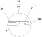
图2为图1所示的输送系统的远端部分结构示意图;FIG. 2 is a schematic structural diagram of the distal end portion of the delivery system shown in FIG. 1;
图3为图1所示的控制组件中第一控制机构结构分解爆炸图,包括收容件和限位件;3 is an exploded exploded view of the structure of the first control mechanism in the control assembly shown in FIG. 1, including a receiving member and a limiting member;
图3A为图3所示的控制组件部分结构放大图;3A is an enlarged view of the partial structure of the control assembly shown in FIG. 3;
图4为图3所示的第一控制机构中收容件结构示意图;FIG. 4 is a schematic structural diagram of a receiving member in the first control mechanism shown in FIG. 3;
图5为图3所示的第一控制机构中限位件结构示意图;FIG. 5 is a schematic structural diagram of the limiting member in the first control mechanism shown in FIG. 3;
图6a至图6c为图5所示的限位件旋转不同角度示意图;6a to 6c are schematic diagrams illustrating the rotation of the limiting member shown in FIG. 5 at different angles;
图7为本发明实施例二的输送装置中第一控制机构结构分解爆炸图,包括收容件和限位件;7 is an exploded exploded view of the structure of the first control mechanism in the conveying device according to the second embodiment of the present invention, including a receiving part and a limiting part;
图8为图7所示的第一控制机构中限位件结构示意图;FIG. 8 is a schematic structural diagram of the limiting member in the first control mechanism shown in FIG. 7;
图9a和图9b为图7所示的第一控制机构近端部分剖面结构示意图,分别示出了限位件与收容件处于不同位置关系时的状态。9a and 9b are schematic cross-sectional structural diagrams of the proximal portion of the first control mechanism shown in FIG. 7, respectively showing states when the limiting member and the receiving member are in different positional relationships.
具体实施方式Detailed ways
为了更好地理解本发明的技术方案和有益效果,以下结合附图对本发明的输送装置做举例说明。以下具体实施例仅为部分优选实施例,并非对本发明的限制。In order to better understand the technical solutions and beneficial effects of the present invention, the delivery device of the present invention is exemplified below with reference to the accompanying drawings. The following specific embodiments are only some preferred embodiments, and are not intended to limit the present invention.
在介入医疗领域,定义靠近操作者的一端为“近端”,远离操作者的一端为“远端”。In the field of interventional medicine, the end close to the operator is defined as the "proximal end", and the end away from the operator is defined as the "distal end".
实施例一Example 1
如图1所示,本实施例的输送装置100包括控制组件10和导管组件20。控制组件10与导管组件20的近端相连,用以控制导管组件20的运动。控制组件10包括第一控制机构11、第二控制机构12和第三控制机构13。其中,第二控制机构12设于第一控制机构11和第三控制机构13之间,第一控制机构11靠近控制组件10的近端设置,第三控制机构13靠近控制组件10的远端设置。同时参考图2,导管组件20包括外管21、中管22和内管23。内管23远端设有螺纹结构,用以与植入体相连;中管22套设于内管23外,方便回收植入体;外管套设于中管22外,并可相对于中管22轴向运动,主要用于实现对植入体的压缩束缚。可以理解的是,在其它实施例中,导管组件可以不包括中管。再次回到图1,第三控制机构13与外管21相连,可以控制外管21的轴向移动;第二控制机构12与中管22相连,可以控制中管22的轴向移动;第一控制机构11与内管23相连,可以控制内管23的轴向移动和周向转动。As shown in FIG. 1 , the
如图3所示,本实施例的第一控制机构11包括中空的壳体14和限位单元15。其中,壳体14可由第一壳体141和第二壳体142组装形成,并且壳体14近端为一实体端面,内管23通过一接头16与壳体近端相连。接头16卡设于第一壳体141和第二壳体142近端端面中心位置。通过接头16可以向内管23内注射液体,例如生理盐水和造影液等。壳体14上还设有径向贯穿其侧壁的通孔144,且通孔144与外表面之间还形成凸台组件143。凸台组件143包括第一凸台1431及第二凸台1432,且第一凸台1431及第二凸台1432之间存在间隙。如图3A所示,第一凸台1431靠近壳体14的内侧,第二凸台1432靠近壳体14的外侧。As shown in FIG. 3 , the
限位单元15包括限位件151和中空的收容件152。收容件152设于壳体14内,且收容件152外径尺寸与壳体14内径尺寸相当,保证收容件152在壳体14内位置稳定,不会产生晃动。且内管23从收容件152内部穿过后与接头16相连。限位件151的一部分穿过壳体14后收容于收容件152内。The limiting
一并参阅图3及图4,收容件152整体呈圆柱状。收容件152的外表面设有一轴向凹槽153和一周向凹槽154。两个凹槽均由收容件152的外表面径向向内凹陷形成,且周向凹槽154的两端连通,即周向凹槽154使得收容件152外表面形成一闭合的环形凹槽。轴向凹槽153的两端均未贯穿收容件152的端面,使得限位件151不会从收容件152的轴向凹槽153内脱离,保证限位件151能在轴向凹槽153内往复运动。轴向凹槽153的开口与壳体14上的通孔144相对,以使得部分限位件151可通过通孔144进入到轴向凹槽153内。轴向凹槽153与周向凹槽154交叉设置,交叉处设有两个第一圆角155和两个第二圆角156。两个第一圆角155和两个第二圆角156间隔设置,两个第一圆角155设置在交叉处的一条对角线上,两个第二圆角156设置在交叉处的另一条对角线上。其中,两个第一圆角155之间的距离大于两个第二圆角156之间的距离。因轴向凹槽与周向凹槽交叉时,交叉处未设置圆角时包括四个尖锐转角,为防止限位件转动时,收容于凹槽内的部分磨损转角,将其中交叉相对的两个转角设置成第二圆角。可以理解的是,在其它实施例中,轴向凹槽和周向凹槽的交叉处可以设置在轴向凹槽的其它位置,只要保证轴向凹槽和周向凹槽连通即可。可以理解的是,在其它实施例中,第一圆角可以用任意形状的切口替代,只要能保证限位件转动即可。Referring to FIG. 3 and FIG. 4 together, the
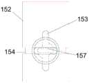
请一并参阅图3及图5,限位件151包括第一止挡体157、转动体158以及连接体159。其中连接体159包括两个相叠的同心圆盘形结构,靠近外侧的第二圆盘1592的半径小于靠近内侧的第二圆盘1591的半径。第一止挡体157和转动体158相对设于连接体159的两侧。且第一止挡体157设于连接体159的内侧,即靠近收容件152的一侧;转动体158设于连接体159的外侧,即远离壳体14外表面的一侧。第一止挡体157为长形结构,且通过壳体14外表面上的通孔144进入到轴向凹槽153内。即第一止挡件157的宽度不大于轴向凹槽153的周向长度以及周向凹槽154的轴向长度,但其轴向长度短于轴向凹槽153的长度,这样能保证第一止挡体157可以在轴向凹槽153轴向移动。为了保证第一止挡体157的位置可以通过旋转在轴向凹槽157和周向凹槽154之间转换,两个凹槽交叉处设置的两个第一圆角155之间的空间应足够允许第一止挡体157通过。并且,壳体14上的通孔144为圆形,圆形直径不小于第一止挡体157的长度,供第一止挡体157转动。可以理解的是,在其它实施例中,通孔144也可以不与第一止挡体157的转动轨迹匹配,此时,在壳体14内壁与收容件152之间有足够的空间供第一止挡体157转动。连接体159夹设于壳体14的两个凸台143之间,使得限位件151可以随着壳体14一起轴向运动或周向转动。其中连接体159上靠近外侧的第二圆盘1592与通孔144处靠近外侧的第二凸台1432的侧面相抵,靠近内侧的第一圆盘1591夹设于两个凸台之间,即第一圆盘1591位于两个凸台143之间的间隙内。可以理解的是,在其它实施例中,轴向凹槽和周向凹槽的交叉处也可以只设置一个第一圆角,只要交叉处的空间能容纳第一止挡体且同时保证第一止挡体的位置能在轴向凹槽和周向凹槽之间转换即可,此时,限位件的最大转动角度为90度。同样可以理解的是,在其它实施例中,交叉处的四个圆角也可以完全相同。Please refer to FIG. 3 and FIG. 5 together, the limiting
转动体158用于手动操作转动限位件151,从而使第一止挡体157的位置在收容件152的两个凹槽之间转换。本实施例中,转动体158的形状与第一止挡体157的形状相同,且转动体158的长度延伸方向也与第一止挡体157的长度延伸方向一致,这样,在限位件151转动过程中,通过转动体158的位置即可确定第一止挡体157所处的位置。可以理解的是,在其它实施例中,转动体的长度延伸方向也可以设置成与第一止挡体垂直;或者,转动体的长度延伸方向与第一止挡体的长度延伸方向成任意锐角,此时,可将连接件可用透明材料制成,方便观察第一止挡体所处的位置;同时,转动体也可以设置成其其它方便手动的形状,只要能方便观察第一止挡体的位置即可。The
可以理解的是,在其其它实施例中,限位件也可以不包括连接体,此时可将转动体的宽度设置成大于壳体上通孔的宽度,保证限位件能架设于壳体上即可。It can be understood that, in other embodiments, the limiting member may not include a connecting body, and the width of the rotating body can be set to be larger than the width of the through hole on the casing to ensure that the limiting member can be erected on the casing. on.
图6a至图6c示出了转动体158带动第一止挡体157旋转到不同角度时的位置图。当转动体158位于图6a所示的位置时,受收容件152管壁的限制,限位件151无法相对于收容件152产生运动,从而壳体14也不能相对于收容件152产生运动,因此,与壳体14相连的内管23也不能相对于输送装置100的其它部分产生运动,可将此状体称为“锁定状态”。当转动体158位于图6b所示的位置时,第一止挡体157收容于轴向凹槽153内,此时,限位件151可在壳体14的带动下相对于收容件152轴向运动,从而,与壳体14相连的内管23也可以一起轴向运动,可将此状态称为“牵拉状态”。当转动体158位于图6c所示的位置时,第一止挡体157收容于周向凹槽154内,此时,限位件151可在壳体14的带动下相对于收容件152周向转动,从而,与壳体14相连的内管23也可以一起周向转动,可将此状态称为“释放状态”。6a to 6c show the position diagrams when the
应当理解,本发明的重点在于第一控制机构对内管的控制,其它控制机构的具体结构将不做详细论述,本领域技术人员可根据实际需求设置其它控制机构对相应导管的控制,只要不影响第一控制机构对内管的控制即可。It should be understood that the focus of the present invention lies in the control of the inner tube by the first control mechanism, and the specific structures of other control mechanisms will not be discussed in detail. Those skilled in the art can set other control mechanisms to control the corresponding catheter according to actual needs, as long as they do not It is sufficient to influence the control of the inner tube by the first control mechanism.
再次参阅图1,本发明包含实施例一输送装置的输送系统300还包括植入体200,本实施例的植入体为人工心脏瓣膜。植入体200与导管组件20可拆卸连接,具体地,植入体可与内管23通过螺纹连接。利用本实施例的输送装置100输送人工心脏瓣膜时,应保证限位件151处于“锁定状态”,避免误操作。将输送装置100的远端输送到指定位置之后,通过第三控制机构13控制外管21朝向近端移动,使连接在内管23远端的人工心脏瓣膜脱离外管21的束缚,从压缩状态扩张,此时,人工心脏瓣膜仍与内管23相连;接着转动限位件151,使其处于“牵拉状态”,轴向前后移动壳体14,使得内管23轴向前后移动,以牵拉人工心脏瓣膜,确认释放位置是否准确可靠;最后,转动限位件151,使其处于“释放状态”,轴向转动壳体14,使得内管23周向旋转,从而使人工心脏瓣膜从与内管23远端的螺纹连接中脱离,实现人工心脏瓣膜的释放。为方便观察限位件在随壳体轴向移动后是否位于两个凹槽的交叉处,方便转换成“释放状态”,壳体和限位件均可以采用透明材料制成。Referring to FIG. 1 again, the
因此,本发明的输送装置在释放人工心脏瓣膜之前,通过第一控制机构实现对内管运动的控制,允许内管轴向运动,通过操作第一控制结构,间接牵拉人工心脏瓣膜,保证释放位置准确可靠之后再使内管转换至可周向旋转的状态,通过周向旋转释放人工心脏瓣膜,降低瓣周漏发生的风险。Therefore, before releasing the artificial heart valve, the delivery device of the present invention controls the movement of the inner tube through the first control mechanism, allowing the inner tube to move axially, and by operating the first control structure, the artificial heart valve is indirectly pulled to ensure release. After the position is accurate and reliable, the inner tube is converted to a state that can be rotated circumferentially, and the artificial heart valve is released through the circumferential rotation, thereby reducing the risk of paravalvular leakage.
实施例二Embodiment 2
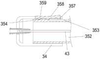
本实施例的输送装置与实施例一的输送装置100结构基本一致,不同之处仅在于第一控制机构31。如图7所示,本实施例的第一控制机构31包括壳体34、收容件352和限位件351。本实施例的壳体34的结构与第一实施例的壳体14基本相同,此处不再赘述。收容件352上设有轴向凹槽353和周向凹槽354,且周向凹槽354靠近轴向凹槽353的近端,二者不连通。如图8所示,限位件351包括按压板358和设于按压板358内侧的第二止挡体357和第三止挡体359。其中第二止挡体357靠近按压板358的远端,第三止挡体359靠近按压板358的近端。按压板358的两侧还设有转轴355。限位件351通过转轴355与壳体34相连,从而使得限位件351可相对于壳体34以转轴355为中心转动。通过按压按压板358的近端或远端可使第三止挡体359收容于周向凹槽354内或第二止挡体357收容于轴向凹槽353内,即第二止挡体357和第三止挡体359不能同时处于凹槽内。如图9a所示,当第二止挡体357收容于轴向凹槽353内时,壳体34和内管43可轴向移动,从而确认人工心脏瓣膜的释放位置是否理想。如图9b所示,当第三止挡体359收容于周向凹槽354内时,壳体34和内管43可周向转动,从而释放人工心脏瓣膜。在操作输送装置的过程中,限位件351处于类似实施例一的“锁定状态”时,需保证壳体34的运动仍受限位件351限制,即第二止挡体357和第三止挡体359均仍部分收容于凹槽内,使得限位件351既不能轴向移动也不能周向转动。因此,需保证第二止挡件357与轴向凹槽353底面相抵时,第三止挡件359才能完全从周向凹槽354中脱离,反之亦然。The structure of the conveying device of this embodiment is basically the same as that of the conveying
可以理解的是,在其它实施例中,周向凹槽也可以靠近轴向凹槽的远端设置,此时,第二止挡体相对于周向凹槽设置,第三止挡体相对于轴向凹槽设置。It can be understood that, in other embodiments, the circumferential groove may also be disposed close to the distal end of the axial groove. In this case, the second stopper body is disposed relative to the circumferential groove, and the third stopper body is disposed relative to the axial groove. set up.
本实施例的输送装置的操作过程与实施例一的输送装置100的操作过程大致相同,只需改变第一控制机构31的操作方式即可,即将转动换成按压的形式。其余不再赘述。The operation process of the conveying device of this embodiment is substantially the same as that of the conveying
本发明的输送装置主要用于人工心脏瓣膜的输送,可以理解的是,当其它医疗器械需要通过牵拉来确定释放位置是否准确时,也可以采用本发明的设计构思。The delivery device of the present invention is mainly used for the delivery of artificial heart valves. It can be understood that when other medical devices need to be pulled to determine whether the release position is accurate, the design concept of the present invention can also be used.
可以理解的是,上述具体实施方式仅为部分优选实施例,并非对本发明的限制,本领域技术人员可以根据实际需求对部分结构做简单替换,在不脱离本发明构思的前提下的做的非实质性改变均在本发明保护范围之内,本发明保护范围以权利要求为准。It can be understood that the above-mentioned specific embodiments are only some preferred embodiments, and are not intended to limit the present invention. Those skilled in the art can simply replace part of the structure according to actual needs, and make other changes without departing from the concept of the present invention. Substantial changes are all within the protection scope of the present invention, and the protection scope of the present invention is subject to the claims.
Claims (9)
Translated fromChinesePriority Applications (2)
| Application Number | Priority Date | Filing Date | Title |
|---|---|---|---|
| CN201811564443.8ACN111345926B (en) | 2018-12-20 | 2018-12-20 | Conveying device and conveying system |
| PCT/CN2019/095426WO2020124999A1 (en) | 2018-12-20 | 2019-07-10 | Delivery device and delivery system |
Applications Claiming Priority (1)
| Application Number | Priority Date | Filing Date | Title |
|---|---|---|---|
| CN201811564443.8ACN111345926B (en) | 2018-12-20 | 2018-12-20 | Conveying device and conveying system |
Publications (2)
| Publication Number | Publication Date |
|---|---|
| CN111345926Atrue CN111345926A (en) | 2020-06-30 |
| CN111345926B CN111345926B (en) | 2021-06-15 |
Family
ID=71101030
Family Applications (1)
| Application Number | Title | Priority Date | Filing Date |
|---|---|---|---|
| CN201811564443.8AActiveCN111345926B (en) | 2018-12-20 | 2018-12-20 | Conveying device and conveying system |
Country Status (2)
| Country | Link |
|---|---|
| CN (1) | CN111345926B (en) |
| WO (1) | WO2020124999A1 (en) |
Cited By (4)
| Publication number | Priority date | Publication date | Assignee | Title |
|---|---|---|---|---|
| CN113367774A (en)* | 2020-07-06 | 2021-09-10 | 杭州启明医疗器械股份有限公司 | Interventional instrument delivery system |
| CN113616398A (en)* | 2021-09-17 | 2021-11-09 | 北京有卓正联医疗科技有限公司 | Handle and conveyor for realizing rapid and slow release of interventional stent |
| CN114052897A (en)* | 2022-01-07 | 2022-02-18 | 深圳佰特微医疗科技有限公司 | Atrial shunt apparatus and ostomy apparatus |
| CN114159190A (en)* | 2021-12-01 | 2022-03-11 | 上海易桥医疗器械有限公司 | Control modules and conveying systems |
Citations (17)
| Publication number | Priority date | Publication date | Assignee | Title |
|---|---|---|---|---|
| US5344397A (en)* | 1992-06-26 | 1994-09-06 | Advanced Surgical, Inc. | Cholangiogram catheter |
| US20130103047A1 (en)* | 2011-10-24 | 2013-04-25 | Medtronic, Inc. | Delivery system assemblies and associated methods for implantable medical devices |
| CN103655004A (en)* | 2012-09-21 | 2014-03-26 | 上海微创医疗器械(集团)有限公司 | Implant Delivery System |
| US20140330219A1 (en)* | 2013-05-06 | 2014-11-06 | Biotronik Ag | Release device for releasing a medical implant from an insertion device, and also insertion device comprising a release device |
| CN104244874A (en)* | 2012-03-12 | 2014-12-24 | 维利欧蒙德股份公司 | Release device for actuating a delivery catheter |
| US20150073540A1 (en)* | 2003-12-23 | 2015-03-12 | Sadra Medical, Inc. | Methods and apparatus for endovascularly replacing a heart valve |
| CN104470471A (en)* | 2012-05-16 | 2015-03-25 | 耶拿阀门科技有限责任公司 | Catheter delivery system for introducing an expandable heart valve prosthesis and medical device for treating a heart valve defect |
| CN204428220U (en)* | 2015-01-04 | 2015-07-01 | 苏州英络医疗器械有限公司 | A kind of intravascular stent induction system |
| US9192495B2 (en)* | 2010-07-23 | 2015-11-24 | Medtronic, Inc. | Attachment mechanism for stent release |
| CN105530893A (en)* | 2013-07-31 | 2016-04-27 | 导管科技有限公司 | Handle assembly for implant delivery apparatus comprising a force limiter, a displacement limiter and/or a brake frame assembly |
| CN205434000U (en)* | 2016-03-08 | 2016-08-10 | 王振杰 | A operation pincers for spiral vessel dilator |
| CN105943212A (en)* | 2015-12-23 | 2016-09-21 | 微创心脉医疗科技(上海)有限公司 | Stent delivering system and handle assembly thereof |
| CN107550524A (en)* | 2016-07-01 | 2018-01-09 | 先健科技(深圳)有限公司 | Conveying device |
| CN108371570A (en)* | 2017-10-24 | 2018-08-07 | 杭州启明医疗器械有限公司 | A kind of recyclable transport system of intervention heart valve of stable operation |
| CN108403269A (en)* | 2018-03-07 | 2018-08-17 | 普霖医疗科技(广州)有限公司 | Integrated bracket conveyer |
| WO2018200942A2 (en)* | 2017-04-27 | 2018-11-01 | Medtronic Inc. | Transcatheter stented prosthesis tensioning and locking systems and devices |
| CN208145087U (en)* | 2016-12-20 | 2018-11-27 | 心凯诺医疗科技(上海)有限公司 | A kind of Self-expanded stent transportation system that can accurately discharge |
Family Cites Families (2)
| Publication number | Priority date | Publication date | Assignee | Title |
|---|---|---|---|---|
| WO2009023221A1 (en)* | 2007-08-13 | 2009-02-19 | William A. Cook Australia Pty. Ltd. | Deployment device |
| US10350066B2 (en)* | 2015-08-28 | 2019-07-16 | Edwards Lifesciences Cardiaq Llc | Steerable delivery system for replacement mitral valve and methods of use |
- 2018
- 2018-12-20CNCN201811564443.8Apatent/CN111345926B/enactiveActive
- 2019
- 2019-07-10WOPCT/CN2019/095426patent/WO2020124999A1/ennot_activeCeased
Patent Citations (17)
| Publication number | Priority date | Publication date | Assignee | Title |
|---|---|---|---|---|
| US5344397A (en)* | 1992-06-26 | 1994-09-06 | Advanced Surgical, Inc. | Cholangiogram catheter |
| US20150073540A1 (en)* | 2003-12-23 | 2015-03-12 | Sadra Medical, Inc. | Methods and apparatus for endovascularly replacing a heart valve |
| US9192495B2 (en)* | 2010-07-23 | 2015-11-24 | Medtronic, Inc. | Attachment mechanism for stent release |
| US20130103047A1 (en)* | 2011-10-24 | 2013-04-25 | Medtronic, Inc. | Delivery system assemblies and associated methods for implantable medical devices |
| CN104244874A (en)* | 2012-03-12 | 2014-12-24 | 维利欧蒙德股份公司 | Release device for actuating a delivery catheter |
| CN104470471A (en)* | 2012-05-16 | 2015-03-25 | 耶拿阀门科技有限责任公司 | Catheter delivery system for introducing an expandable heart valve prosthesis and medical device for treating a heart valve defect |
| CN103655004A (en)* | 2012-09-21 | 2014-03-26 | 上海微创医疗器械(集团)有限公司 | Implant Delivery System |
| US20140330219A1 (en)* | 2013-05-06 | 2014-11-06 | Biotronik Ag | Release device for releasing a medical implant from an insertion device, and also insertion device comprising a release device |
| CN105530893A (en)* | 2013-07-31 | 2016-04-27 | 导管科技有限公司 | Handle assembly for implant delivery apparatus comprising a force limiter, a displacement limiter and/or a brake frame assembly |
| CN204428220U (en)* | 2015-01-04 | 2015-07-01 | 苏州英络医疗器械有限公司 | A kind of intravascular stent induction system |
| CN105943212A (en)* | 2015-12-23 | 2016-09-21 | 微创心脉医疗科技(上海)有限公司 | Stent delivering system and handle assembly thereof |
| CN205434000U (en)* | 2016-03-08 | 2016-08-10 | 王振杰 | A operation pincers for spiral vessel dilator |
| CN107550524A (en)* | 2016-07-01 | 2018-01-09 | 先健科技(深圳)有限公司 | Conveying device |
| CN208145087U (en)* | 2016-12-20 | 2018-11-27 | 心凯诺医疗科技(上海)有限公司 | A kind of Self-expanded stent transportation system that can accurately discharge |
| WO2018200942A2 (en)* | 2017-04-27 | 2018-11-01 | Medtronic Inc. | Transcatheter stented prosthesis tensioning and locking systems and devices |
| CN108371570A (en)* | 2017-10-24 | 2018-08-07 | 杭州启明医疗器械有限公司 | A kind of recyclable transport system of intervention heart valve of stable operation |
| CN108403269A (en)* | 2018-03-07 | 2018-08-17 | 普霖医疗科技(广州)有限公司 | Integrated bracket conveyer |
Cited By (7)
| Publication number | Priority date | Publication date | Assignee | Title |
|---|---|---|---|---|
| CN113367774A (en)* | 2020-07-06 | 2021-09-10 | 杭州启明医疗器械股份有限公司 | Interventional instrument delivery system |
| CN113367774B (en)* | 2020-07-06 | 2022-07-19 | 杭州启明医疗器械股份有限公司 | Interventional instrument delivery system |
| CN113616398A (en)* | 2021-09-17 | 2021-11-09 | 北京有卓正联医疗科技有限公司 | Handle and conveyor for realizing rapid and slow release of interventional stent |
| CN113616398B (en)* | 2021-09-17 | 2023-12-29 | 北京有卓正联医疗科技有限公司 | Handle and conveyer for realizing rapid and slow release of interventional stent |
| CN114159190A (en)* | 2021-12-01 | 2022-03-11 | 上海易桥医疗器械有限公司 | Control modules and conveying systems |
| CN114052897A (en)* | 2022-01-07 | 2022-02-18 | 深圳佰特微医疗科技有限公司 | Atrial shunt apparatus and ostomy apparatus |
| CN114052897B (en)* | 2022-01-07 | 2022-04-12 | 深圳佰特微医疗科技有限公司 | Atrial shunt apparatus and ostomy apparatus |
Also Published As
| Publication number | Publication date |
|---|---|
| CN111345926B (en) | 2021-06-15 |
| WO2020124999A1 (en) | 2020-06-25 |
Similar Documents
| Publication | Publication Date | Title |
|---|---|---|
| US12279956B2 (en) | Method and apparatus for percutaneous delivery and deployment of a cardiac valve prosthesis | |
| US11938028B2 (en) | Method for implanting a prosthetic heart valve | |
| CN111345926A (en) | Conveying device and conveying system | |
| US10856982B2 (en) | Transapical mitral valve delivery system | |
| CN222566033U (en) | Reverse flow heart valve conveyor and conveying system with stable operation | |
| EP2898857B1 (en) | Implant conveying system | |
| US5370685A (en) | Endovascular aortic valve replacement | |
| US10010411B2 (en) | Devices and methods for preparing a transcatheter heart valve system | |
| WO2019128653A1 (en) | Medical appliance deployment apparatus | |
| KR20200024750A (en) | Delivery system for transcatheter artificial heart valve | |
| CN113893064A (en) | Methods and systems for rapid retrieval of transcatheter heart valve delivery systems | |
| US20110264199A1 (en) | Transcatheter Prosthetic Heart Valve Delivery System with Flush Report | |
| EP4218673A1 (en) | Implant delivery handle, and delivery system and operating method therefor | |
| EP3881801B1 (en) | Improvements in or relating to the delivery and unsheathing of prosthetic heart valves | |
| US11779462B2 (en) | Conveyor and conveyor system | |
| WO2019128702A1 (en) | Medical instrument delivery apparatus | |
| WO2023279492A1 (en) | Implant conveying handle, implant system, implant conveying system, and working method thereof | |
| CN109984869B (en) | Heart valve prosthesis delivery device | |
| WO2020200149A1 (en) | Drive handle used for delivering implant and delivery system | |
| WO2023231446A1 (en) | Implant release directaional marking device, implant conveying system and working method therefor | |
| WO2022233338A1 (en) | Implant delivery handle, implant system, and implant delivery system and operation method therefor | |
| WO2022057252A1 (en) | Implant | |
| CN211934440U (en) | Conveyor and conveying system | |
| CN118717363A (en) | Conveyors and conveying systems | |
| CN118591356A (en) | Prosthesis for a heart valve and method of arranging the prosthesis in an implant device |
Legal Events
| Date | Code | Title | Description |
|---|---|---|---|
| PB01 | Publication | ||
| PB01 | Publication | ||
| SE01 | Entry into force of request for substantive examination | ||
| SE01 | Entry into force of request for substantive examination | ||
| GR01 | Patent grant | ||
| GR01 | Patent grant | ||
| TR01 | Transfer of patent right | ||
| TR01 | Transfer of patent right | Effective date of registration:20231227 Address after:518000 1604, Xianjian technology building, No. 22, Keji South 12th Road, gaoxinyuan community, Yuehai street, Nanshan District, Shenzhen, Guangdong Province Patentee after:Shenzhen Jianxin Medical Technology Co.,Ltd. Address before:518000 1st-5th Floor of Saiba Research Building, Langshan Second Road, North District of Nanshan High-tech Industrial Park, Shenzhen City, Guangdong Province Patentee before:LIFETECH SCIENTIFIC (SHENZHEN) Co.,Ltd. |