CN111345813A - Visualizing different heart rhythms using different timing pattern displays - Google Patents
Visualizing different heart rhythms using different timing pattern displaysDownload PDFInfo
- Publication number
- CN111345813A CN111345813ACN201911324346.6ACN201911324346ACN111345813ACN 111345813 ACN111345813 ACN 111345813ACN 201911324346 ACN201911324346 ACN 201911324346ACN 111345813 ACN111345813 ACN 111345813A
- Authority
- CN
- China
- Prior art keywords
- location
- heart
- cycle length
- cardiac cycle
- arrhythmia
- Prior art date
- Legal status (The legal status is an assumption and is not a legal conclusion. Google has not performed a legal analysis and makes no representation as to the accuracy of the status listed.)
- Granted
Links
Images


Classifications
- A—HUMAN NECESSITIES
- A61—MEDICAL OR VETERINARY SCIENCE; HYGIENE
- A61B—DIAGNOSIS; SURGERY; IDENTIFICATION
- A61B5/00—Measuring for diagnostic purposes; Identification of persons
- A61B5/72—Signal processing specially adapted for physiological signals or for diagnostic purposes
- A61B5/7235—Details of waveform analysis
- A61B5/7264—Classification of physiological signals or data, e.g. using neural networks, statistical classifiers, expert systems or fuzzy systems
- A—HUMAN NECESSITIES
- A61—MEDICAL OR VETERINARY SCIENCE; HYGIENE
- A61B—DIAGNOSIS; SURGERY; IDENTIFICATION
- A61B5/00—Measuring for diagnostic purposes; Identification of persons
- A61B5/24—Detecting, measuring or recording bioelectric or biomagnetic signals of the body or parts thereof
- A61B5/316—Modalities, i.e. specific diagnostic methods
- A61B5/318—Heart-related electrical modalities, e.g. electrocardiography [ECG]
- A61B5/339—Displays specially adapted therefor
- A61B5/341—Vectorcardiography [VCG]
- A—HUMAN NECESSITIES
- A61—MEDICAL OR VETERINARY SCIENCE; HYGIENE
- A61B—DIAGNOSIS; SURGERY; IDENTIFICATION
- A61B5/00—Measuring for diagnostic purposes; Identification of persons
- A61B5/24—Detecting, measuring or recording bioelectric or biomagnetic signals of the body or parts thereof
- A61B5/316—Modalities, i.e. specific diagnostic methods
- A61B5/318—Heart-related electrical modalities, e.g. electrocardiography [ECG]
- A61B5/346—Analysis of electrocardiograms
- A61B5/349—Detecting specific parameters of the electrocardiograph cycle
- A61B5/363—Detecting tachycardia or bradycardia
- A—HUMAN NECESSITIES
- A61—MEDICAL OR VETERINARY SCIENCE; HYGIENE
- A61B—DIAGNOSIS; SURGERY; IDENTIFICATION
- A61B5/00—Measuring for diagnostic purposes; Identification of persons
- A61B5/24—Detecting, measuring or recording bioelectric or biomagnetic signals of the body or parts thereof
- A61B5/25—Bioelectric electrodes therefor
- A61B5/279—Bioelectric electrodes therefor specially adapted for particular uses
- A61B5/28—Bioelectric electrodes therefor specially adapted for particular uses for electrocardiography [ECG]
- A61B5/283—Invasive
- A—HUMAN NECESSITIES
- A61—MEDICAL OR VETERINARY SCIENCE; HYGIENE
- A61B—DIAGNOSIS; SURGERY; IDENTIFICATION
- A61B5/00—Measuring for diagnostic purposes; Identification of persons
- A61B5/24—Detecting, measuring or recording bioelectric or biomagnetic signals of the body or parts thereof
- A61B5/316—Modalities, i.e. specific diagnostic methods
- A61B5/318—Heart-related electrical modalities, e.g. electrocardiography [ECG]
- A61B5/333—Recording apparatus specially adapted therefor
- A61B5/335—Recording apparatus specially adapted therefor using integrated circuit memory devices
- A—HUMAN NECESSITIES
- A61—MEDICAL OR VETERINARY SCIENCE; HYGIENE
- A61B—DIAGNOSIS; SURGERY; IDENTIFICATION
- A61B5/00—Measuring for diagnostic purposes; Identification of persons
- A61B5/24—Detecting, measuring or recording bioelectric or biomagnetic signals of the body or parts thereof
- A61B5/316—Modalities, i.e. specific diagnostic methods
- A61B5/318—Heart-related electrical modalities, e.g. electrocardiography [ECG]
- A61B5/339—Displays specially adapted therefor
- A—HUMAN NECESSITIES
- A61—MEDICAL OR VETERINARY SCIENCE; HYGIENE
- A61B—DIAGNOSIS; SURGERY; IDENTIFICATION
- A61B5/00—Measuring for diagnostic purposes; Identification of persons
- A61B5/24—Detecting, measuring or recording bioelectric or biomagnetic signals of the body or parts thereof
- A61B5/316—Modalities, i.e. specific diagnostic methods
- A61B5/318—Heart-related electrical modalities, e.g. electrocardiography [ECG]
- A61B5/346—Analysis of electrocardiograms
- A61B5/349—Detecting specific parameters of the electrocardiograph cycle
- A61B5/364—Detecting abnormal ECG interval, e.g. extrasystoles, ectopic heartbeats
- A—HUMAN NECESSITIES
- A61—MEDICAL OR VETERINARY SCIENCE; HYGIENE
- A61B—DIAGNOSIS; SURGERY; IDENTIFICATION
- A61B5/00—Measuring for diagnostic purposes; Identification of persons
- A61B5/68—Arrangements of detecting, measuring or recording means, e.g. sensors, in relation to patient
- A61B5/6846—Arrangements of detecting, measuring or recording means, e.g. sensors, in relation to patient specially adapted to be brought in contact with an internal body part, i.e. invasive
- A61B5/6847—Arrangements of detecting, measuring or recording means, e.g. sensors, in relation to patient specially adapted to be brought in contact with an internal body part, i.e. invasive mounted on an invasive device
- A61B5/6852—Catheters
- A—HUMAN NECESSITIES
- A61—MEDICAL OR VETERINARY SCIENCE; HYGIENE
- A61B—DIAGNOSIS; SURGERY; IDENTIFICATION
- A61B5/00—Measuring for diagnostic purposes; Identification of persons
- A61B5/68—Arrangements of detecting, measuring or recording means, e.g. sensors, in relation to patient
- A61B5/6846—Arrangements of detecting, measuring or recording means, e.g. sensors, in relation to patient specially adapted to be brought in contact with an internal body part, i.e. invasive
- A61B5/6867—Arrangements of detecting, measuring or recording means, e.g. sensors, in relation to patient specially adapted to be brought in contact with an internal body part, i.e. invasive specially adapted to be attached or implanted in a specific body part
- A61B5/6869—Heart
- G—PHYSICS
- G16—INFORMATION AND COMMUNICATION TECHNOLOGY [ICT] SPECIALLY ADAPTED FOR SPECIFIC APPLICATION FIELDS
- G16H—HEALTHCARE INFORMATICS, i.e. INFORMATION AND COMMUNICATION TECHNOLOGY [ICT] SPECIALLY ADAPTED FOR THE HANDLING OR PROCESSING OF MEDICAL OR HEALTHCARE DATA
- G16H50/00—ICT specially adapted for medical diagnosis, medical simulation or medical data mining; ICT specially adapted for detecting, monitoring or modelling epidemics or pandemics
- G16H50/20—ICT specially adapted for medical diagnosis, medical simulation or medical data mining; ICT specially adapted for detecting, monitoring or modelling epidemics or pandemics for computer-aided diagnosis, e.g. based on medical expert systems
- G—PHYSICS
- G16—INFORMATION AND COMMUNICATION TECHNOLOGY [ICT] SPECIALLY ADAPTED FOR SPECIFIC APPLICATION FIELDS
- G16H—HEALTHCARE INFORMATICS, i.e. INFORMATION AND COMMUNICATION TECHNOLOGY [ICT] SPECIALLY ADAPTED FOR THE HANDLING OR PROCESSING OF MEDICAL OR HEALTHCARE DATA
- G16H50/00—ICT specially adapted for medical diagnosis, medical simulation or medical data mining; ICT specially adapted for detecting, monitoring or modelling epidemics or pandemics
- G16H50/30—ICT specially adapted for medical diagnosis, medical simulation or medical data mining; ICT specially adapted for detecting, monitoring or modelling epidemics or pandemics for calculating health indices; for individual health risk assessment
- A—HUMAN NECESSITIES
- A61—MEDICAL OR VETERINARY SCIENCE; HYGIENE
- A61B—DIAGNOSIS; SURGERY; IDENTIFICATION
- A61B5/00—Measuring for diagnostic purposes; Identification of persons
- A61B5/24—Detecting, measuring or recording bioelectric or biomagnetic signals of the body or parts thereof
- A61B5/316—Modalities, i.e. specific diagnostic methods
- A61B5/369—Electroencephalography [EEG]
- A—HUMAN NECESSITIES
- A61—MEDICAL OR VETERINARY SCIENCE; HYGIENE
- A61B—DIAGNOSIS; SURGERY; IDENTIFICATION
- A61B5/00—Measuring for diagnostic purposes; Identification of persons
- A61B5/74—Details of notification to user or communication with user or patient; User input means
- A61B5/742—Details of notification to user or communication with user or patient; User input means using visual displays
- A61B5/7425—Displaying combinations of multiple images regardless of image source, e.g. displaying a reference anatomical image with a live image
Landscapes
- Health & Medical Sciences (AREA)
- Life Sciences & Earth Sciences (AREA)
- Engineering & Computer Science (AREA)
- Public Health (AREA)
- Medical Informatics (AREA)
- Cardiology (AREA)
- Biomedical Technology (AREA)
- Pathology (AREA)
- General Health & Medical Sciences (AREA)
- Physics & Mathematics (AREA)
- Molecular Biology (AREA)
- Surgery (AREA)
- Animal Behavior & Ethology (AREA)
- Heart & Thoracic Surgery (AREA)
- Biophysics (AREA)
- Veterinary Medicine (AREA)
- Artificial Intelligence (AREA)
- Primary Health Care (AREA)
- Epidemiology (AREA)
- Databases & Information Systems (AREA)
- Data Mining & Analysis (AREA)
- Signal Processing (AREA)
- Physiology (AREA)
- Psychiatry (AREA)
- Computer Vision & Pattern Recognition (AREA)
- Mathematical Physics (AREA)
- Fuzzy Systems (AREA)
- Evolutionary Computation (AREA)
- Microelectronics & Electronic Packaging (AREA)
- Nuclear Medicine, Radiotherapy & Molecular Imaging (AREA)
- Radiology & Medical Imaging (AREA)
- Measurement And Recording Of Electrical Phenomena And Electrical Characteristics Of The Living Body (AREA)
- Ultra Sonic Daignosis Equipment (AREA)
Abstract
Translated fromChinese
Description
Translated fromChinese技术领域technical field
本发明整体涉及电解剖标测,并且具体地讲涉及用于心脏电解剖标测的方法和系统。The present invention relates generally to electroanatomical mapping, and in particular to methods and systems for cardiac electroanatomical mapping.
背景技术Background technique
先前在专利文献中讨论了用于心腔电解剖标测的技术。例如,美国专利申请公布2016/0089048描述了从包括心室通道、标测通道和多个参考通道的至少四个多通道心电描记图信号来确定局部激活时间(LAT)的自动方法。该方法包括:(a)存储心脏通道信号,(b)使用该心室通道信号和标测通道信号以及第一参考通道信号来在多个标测通道位置处计算LAT值,(c)监测第一参考通道信号的时序稳定性,以及(d)如果所监测的信号的时序稳定性降至低于稳定性标准,则使用第二参考通道的信号来确定LAT值。尽管存在时序稳定性的损失,但LAT值的显著损失可避免。Techniques for electroanatomical mapping of cardiac chambers have been previously discussed in the patent literature. For example, US Patent Application Publication 2016/0089048 describes an automated method for determining local activation time (LAT) from at least four multi-channel electrocardiogram signals including a ventricular channel, a mapping channel, and a plurality of reference channels. The method includes: (a) storing the cardiac channel signal, (b) using the ventricular channel signal and the mapped channel signal and the first reference channel signal to calculate LAT values at a plurality of mapped channel locations, (c) monitoring the first the timing stability of the reference channel signal, and (d) if the timing stability of the monitored signal falls below a stability criterion, using the signal of the second reference channel to determine the LAT value. Notwithstanding the loss of timing stability, a significant loss of LAT value can be avoided.
又如,美国专利申请公布2016/0089050描述了一种解剖标测系统和方法,该解剖标测系统和方法包括被配置成检测心脏活动的激活信号的标测电极。处理系统被配置成记录检测到的激活信号,并在生理活动的每个实例期间为每个感测的激活信号生成矢量场。该处理系统确定起始时间和另选的起始时间候选项,基于初始向量场和来自模板库的向量场模板之间的相似度来识别初始向量场模板,然后基于起始时间候选项和初始向量场模板之间的相似度来确定每个激活信号的优化起始时间。As another example, US Patent Application Publication 2016/0089050 describes an anatomical mapping system and method that includes mapping electrodes configured to detect activation signals of cardiac activity. The processing system is configured to record the detected activation signals and generate a vector field for each sensed activation signal during each instance of the physiological activity. The processing system determines a start time and an alternative start time candidate, identifies an initial vector field template based on the similarity between the initial vector field and a vector field template from a template library, and then based on the start time candidate and the initial The similarity between the vector field templates to determine the optimal start time for each activation signal.
美国专利申请公布2011/0251505描述了用于促进心脏信息重建以指示心律紊乱的来源的系统、组件和方法,该心脏信息表示与患者的心脏相关联的复杂的节律紊乱。该复杂的节律紊乱可通过施加能量以改变节律紊乱的来源来治疗。US Patent Application Publication 2011/0251505 describes systems, components and methods for facilitating reconstruction of cardiac information indicative of complex rhythm disturbances associated with the patient's heart to indicate the source of cardiac rhythm disturbances. This complex rhythm disturbance can be treated by applying energy to alter the source of the rhythm disturbance.
发明内容SUMMARY OF THE INVENTION
本发明的一个实施方案提供了一种方法,该方法包括接收在心脏的一部分之上的给定位置处测量的心电图(ECG)。基于所测量的ECG,在给定时间间隔内识别节律图案。该节律图案对应于当前心动周期长度和前一个心动周期长度之间的关系。基于所识别的节律图案,将位置的分类确定为显示规则图案或显示心律失常。根据该分类来以图形方式编码该位置。将该以图形方式编码的位置覆盖在心脏的该部分的解剖标测图上One embodiment of the present invention provides a method comprising receiving an electrocardiogram (ECG) measured at a given location over a portion of the heart. Based on the measured ECG, rhythm patterns are identified within a given time interval. The rhythm pattern corresponds to the relationship between the current cardiac cycle length and the previous cardiac cycle length. Based on the identified rhythm pattern, a classification of the location is determined as showing a regular pattern or showing an arrhythmia. The location is graphically encoded according to the classification. overlay the graphically coded position on an anatomical map of that part of the heart
在一些实施方案中,识别节律图案包括计算当前心动周期长度和前一个心动周期长度之间的差值。In some embodiments, identifying the rhythm pattern includes calculating the difference between the current cardiac cycle length and the previous cardiac cycle length.
在一些实施方案中,将位置分类为显示心律失常包括对心律失常的类型进行分类。In some embodiments, classifying the location as indicative of an arrhythmia includes classifying a type of arrhythmia.
在一个实施方案中,覆盖该以图形方式编码的位置包括生成心脏的该部分的时空电解剖标测图。在另一个实施方案中,该方法还包括使用用于电解剖标测的基于导管的系统来测量ECG。In one embodiment, overlaying the graphically encoded location includes generating a spatiotemporal electroanatomical map of the portion of the heart. In another embodiment, the method further comprises measuring the ECG using a catheter-based system for electroanatomical mapping.
根据本发明的实施方案,本文另外提供了包括存储器和处理器的系统。该存储器被配置成存储在心脏的一部分之上的给定位置处测量的心电图(ECG)。该处理器被配置成基于所测量的ECG来在给定时间间隔内识别节律图案。该节律图案对应于当前心动周期长度和前一个心动周期长度之间的关系。该处理器另外被配置成基于所识别的节律图案将位置的分类确定为显示规则图案或显示心律失常。该处理器还被配置成根据该分类以图形方式编码该位置以及将该以图形方式编码的位置覆盖在该心脏的该部分的解剖标测图上。In accordance with embodiments of the present invention, systems including a memory and a processor are additionally provided herein. The memory is configured to store an electrocardiogram (ECG) measured at a given location over a portion of the heart. The processor is configured to identify a rhythm pattern within a given time interval based on the measured ECG. The rhythm pattern corresponds to the relationship between the current cardiac cycle length and the previous cardiac cycle length. The processor is additionally configured to determine the classification of the location as showing a regular pattern or showing a cardiac arrhythmia based on the identified rhythm pattern. The processor is further configured to graphically encode the location according to the classification and overlay the graphically encoded location on the anatomical map of the portion of the heart.
结合附图,通过以下对本发明的实施方案的详细描述,将更全面地理解本发明,其中:The present invention will be more fully understood from the following detailed description of embodiments of the present invention in conjunction with the accompanying drawings, wherein:
附图说明Description of drawings
图1为根据本发明的实施方案的用于电解剖标测的系统的示意性图解;1 is a schematic illustration of a system for electroanatomical mapping according to an embodiment of the present invention;
图2A至图2C为根据本发明的实施方案的局部心跳时序图案的示意性例示散布图;2A-2C are schematic illustration scatter plots of local heartbeat timing patterns according to embodiments of the present invention;
图3为根据本发明的实施方案的心腔的时空电解剖标测图的示意性图解;并且3 is a schematic illustration of a spatiotemporal electroanatomical map of cardiac chambers according to an embodiment of the present invention; and
图4为根据本发明的实施方案的示意性地示出用于生成心腔的时空电解剖标测图的方法和算法的流程图。4 is a flow diagram schematically illustrating a method and algorithm for generating a spatiotemporal electroanatomical map of cardiac chambers, according to an embodiment of the present invention.
具体实施方式Detailed ways
概述Overview
基于导管的电解剖标测规程的一个重要用途是识别作为心律失常的潜在起源或传导路径的心内组织位置。对于诊断,可基于对导管在某个组织位置处记录的电生理(EP)活动的节律图案进行分析来将该位置表征为正常或异常。An important use of catheter-based electroanatomical mapping procedures is to identify intracardiac tissue locations that are potential origins or conduction pathways for cardiac arrhythmias. For diagnosis, a tissue location can be characterized as normal or abnormal based on analysis of the rhythmic pattern of electrophysiological (EP) activity recorded by the catheter at that location.
例如,在心内心电图(ECG)中见到的此类局部记录的节律图案可由心脏EP激活的心动周期长度(即,周期性)的属性来简明地表示。通常意味着正常窦性节律的可重复周期长度指示健康且正常的心脏组织位置。另一方面,高度可变的周期长度指示异常的组织位置,心律失常源自该组织位置或通过该组织位置传播。For example, such locally recorded rhythm patterns seen in an intracardiac electrogram (ECG) can be concisely represented by the property of cardiac cycle length (ie, periodicity) of cardiac EP activation. It generally means that a repeatable cycle length of normal sinus rhythm is indicative of healthy and normal cardiac tissue location. On the other hand, a highly variable cycle length is indicative of an abnormal tissue location through which the arrhythmia originates or propagates.
目前,内科医生可通过手动检查心腔的不同区域来分析心腔的电解剖标测图,以尝试识别出心律失常的起源和/或路径。然而,这种类型的检查需要费力、费时的细致工作。Currently, physicians can analyze electroanatomical maps of cardiac chambers by manually examining different regions of the cardiac chambers in an attempt to identify the origin and/or path of the arrhythmia. However, this type of inspection requires laborious, time-consuming and meticulous work.
下文所述的本发明的实施方案生成心脏的一部分诸如心腔的表面组织的时空电解剖标测图(在下文也称为“时空EP标测图”)。时空EP标测图以图形方式将组织位置编码为健康的或异常的。此外,用于生成时空EP标测图的所公开的技术可识别和编码不同类型的心律失常行为。Embodiments of the invention described below generate spatiotemporal electroanatomical maps (hereafter also referred to as "spatiotemporal EP maps") of a portion of the heart, such as the surface tissue of the cardiac chambers. Spatiotemporal EP mapping graphically encodes tissue location as healthy or abnormal. Furthermore, the disclosed techniques for generating spatiotemporal EP maps can identify and encode different types of arrhythmic behavior.
所公开的时空EP标测图是通过对由心脏的一部分之上的组织位置表现出的时序图案(诸如在心腔壁组织之上表现出的那些)进行分类来产生的。对于任何特定组织位置,由处理器将“当前的”时间段(即,周期长度)与前一个或“先前的”时间段进行比较来识别时序图案。该时序图案可由处理器在几秒的典型时间间隔内识别。这样,组织位置的时序图案指示该位置处的节律图案。The disclosed spatiotemporal EP maps are generated by classifying temporal patterns exhibited by tissue locations over a portion of the heart, such as those exhibited over cardiac chamber wall tissue. For any particular tissue location, the timing pattern is identified by the processor comparing the "current" time period (ie, cycle length) to the previous or "previous" time period. This timing pattern can be recognized by the processor in a typical time interval of a few seconds. In this way, the temporal pattern of a tissue location is indicative of the rhythmic pattern at that location.
表现出正常窦性节律(例如,具有在几秒内可足够重复的心跳率)的组织位置产生基本上给出单个点的时序图案,如下文所述。然而,表现出心律失常的组织位置将产生不同于该窦性图案的时序图案,并且每种不同类型的心律失常通常将具有不同的特征时序图案,如下所示。Tissue locations exhibiting a normal sinus rhythm (eg, with a heart rate that is sufficiently repeatable within a few seconds) produces a temporal pattern that essentially gives a single point, as described below. However, tissue locations exhibiting arrhythmias will produce timing patterns that differ from this sinus pattern, and each different type of arrhythmia will typically have a different characteristic timing pattern, as shown below.
在一些实施方案中,提供了存储器,其被配置成存储在心脏的一部分上的给定位置处测量的心电图(ECG)。处理器被配置成(a)基于所测量的ECG,在给定时间间隔内识别节律图案,该节律图案对应于当前心动周期长度和前一个心动周期长度之间的关系,以及(b)基于所识别的节律图案,将该位置的分类确定为显示规则图案(即,正常)或显示心律失常。该处理器还被配置成根据该分类以图形方式编码该位置以及将该以图形方式编码的位置覆盖在心脏的该部分的解剖标测图上。In some embodiments, a memory is provided that is configured to store an electrocardiogram (ECG) measured at a given location on a portion of the heart. The processor is configured to (a) identify a rhythm pattern within a given time interval based on the measured ECG, the rhythm pattern corresponding to the relationship between the current cardiac cycle length and the previous cardiac cycle length, and (b) based on the measured ECG The identified rhythm pattern, the classification of the location is determined as showing a regular pattern (ie, normal) or showing an arrhythmia. The processor is further configured to graphically encode the location according to the classification and overlay the graphically encoded location on the anatomical map of the portion of the heart.
在一个实施方案中,该处理器使用心腔的解剖标测图上的位置的不同时序图案来覆盖该编码,以创建心腔的时空标测图,并且该时空标测图可帮助内科医生定位心律失常的起源和/或指示心律失常类型。In one embodiment, the processor overlays the encoding with different temporal patterns of locations on the anatomical map of the heart chambers to create a spatiotemporal map of the heart chambers, and the spatiotemporal map can assist the physician in positioning Origin of the arrhythmia and/or indication of the type of arrhythmia.
通常,处理器利用包含特定算法的软件进行编程,该算法允许处理器执行上文列出的处理器相关步骤和功能中的每个。Typically, the processor is programmed with software containing specific algorithms that allow the processor to perform each of the processor-related steps and functions listed above.
所公开的时空电解剖标测技术为内科医生提供心腔组织的正常区域与异常区域的清晰视觉表示,并且因此可有利于更容易地对心律失常进行诊断和治疗选择。The disclosed spatiotemporal electroanatomical mapping techniques provide physicians with a clear visual representation of normal versus abnormal regions of cardiac chamber tissue, and thus may facilitate easier diagnosis and treatment selection of cardiac arrhythmias.
系统描述System specification
图1为根据本发明的实施方案的用于电解剖标测的系统的示意性图解;图1示出使用电解剖导管29执行患者25的心脏23的电解剖标测的内科医生27。导管29在其远端处包括可为机械柔性的一个或多个臂20,每个臂与一个或多个电极22耦接。在标测规程期间,电极22从心脏23的组织获取并且/或者向心脏23的组织注入信号。处理器28经由电接口35接收这些信号,并且使用这些信号中包含的信息来构造电解剖标测图31,处理器28将该电解剖标测图保存在存储器33中以供进一步使用,例如,用于产生所公开的时空电解剖标测图,如下所述。在该规程期间和/或之后,处理器28可在显示器26上显示电解剖标测图31。1 is a schematic illustration of a system for electroanatomical mapping according to an embodiment of the present invention; FIG. 1 shows a
在该规程期间,跟踪系统用于跟踪感测电极22的相应位置,使得这些信号中的每种信号可以与信号获取位置相关联。例如,可使用美国专利8,456,182中描述的由Biosense-Webster(Irvine,California)制造的有源电流位置(ACL)系统,该专利的公开内容以引用方式并入本文。在ACL系统中,处理器基于在每个感测电极22与耦接到患者25的皮肤的多个表面电极24之间测量的阻抗来估计电极的相应位置。例如,三个表面电极24可耦接到患者的胸部,另外三个表面电极可耦接到患者的背部。(为了便于说明,图1中仅示出一个表面电极。)处理器将从电极22接收的任何给定阻抗信号与心脏23中的获取信号的位置相关联。During this procedure, a tracking system is used to track the respective positions of the
图1中所示的示例性图解完全是为了概念清晰而选择的。可使用其他跟踪方法,例如基于测量电压信号的方法,如

处理器28通常包括具有经编程以执行本文所述功能的软件的通用计算机。该软件可通过网络以电子形式被下载到计算机,例如或者其可另选地或另外地设置和/或存储在非临时性有形介质(诸如磁存储器、光存储器或电子存储器)上。具体地讲,处理器28运行如本文所公开的包括在图4中的专用算法,该专用算法使得处理器28能够执行所公开的步骤,如下文进一步描述的。
使用不同心律的不同时序图案显示Display using different timing patterns for different heart rhythms
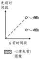
图2A至图2C是根据本发明的实施方案的局部心跳时序图案的示意性例示散布图。所有三个图针对紧接的前一个或“先前的”时间段绘制“当前的”时间段,即周期长度。2A-2C are schematic illustration scatter plots of local heartbeat timing patterns according to embodiments of the present invention. All three graphs plot the "current" time period, ie the period length, against the immediately preceding or "previous" time period.
图2A是以规则方式(例如,在正常窦性节律中)工作的组织上的位置的时序图案绘图。如图所示,该时序图案绘图基本上给出一个点46a,因为EP激活之间的当前周期长度和先前周期长度在正常心脏组织中非常相似。Figure 2A is a time-series pattern plot of locations on tissue working in a regular fashion (eg, in normal sinus rhythm). As shown, this timing pattern plot essentially gives a point 46a because the current cycle length and previous cycle length between EP activations are very similar in normal cardiac tissue.
图2B为表现出特定类型(称为“1型”)的心律失常的组织上的位置的时序图案绘图。如图所示,“1型”心律失常的特征在于连续周期长度之间的单个值变化46b。Figure 2B is a plot of time-series patterns of locations on tissue exhibiting a particular type of arrhythmia (referred to as "Type 1"). As shown, a "Type 1" arrhythmia is characterized by a single value change 46b between consecutive cycle lengths.
图2C是表现出另一种类型(称为“2型”)的心律失常的组织上的另一个位置的时序图案绘图。如图所示,“2型”心律失常的特征在于周期长度以更复杂的方式例如在三个值46c之间变化。还如图所示,根据每个相应位置的相应类型的时序图案绘图,通过为每个相应位置分配包括图形图案44a、44b和44c的空间占用量(即,将每个位置分类为正常或心律失常,其中一种类型或其他类型的心律失常在该位置处示出)来以图形方式编码每种类型的时间图案。Figure 2C is a time-series pattern plot of another location on tissue exhibiting another type (referred to as "Type 2") arrhythmia. As shown, "Type 2" arrhythmias are characterized by cycle lengths that vary in a more complex manner, eg, between three
图2A至图2C中所示的示例性图解完全是为了概念清晰而选择的。图2A至图2C仅示出了与本发明的实施方案相关的部分。例如,在该散布图中可发生一些变化,形式为围绕每个点的加宽“云”。可应用附加的数据处理步骤诸如心跳徘徊的阈值化,以最小化非决定性的加宽的时序图案绘图。在另选的实施方案中,可建立其他分类,诸如对散布图中所见的时序图案进行量化的那些分类。The exemplary diagrams shown in FIGS. 2A-2C have been chosen purely for conceptual clarity. Figures 2A to 2C show only parts relevant to embodiments of the present invention. For example, some variation can occur in this scatter plot in the form of a widening "cloud" around each point. Additional data processing steps such as thresholding of heartbeat wandering can be applied to minimize indeterminate broadened timing pattern plots. In alternative embodiments, other classifications may be established, such as those that quantify the timing patterns seen in the scatter plot.
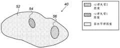
图3为根据本发明的实施方案的心腔的时空电解剖标测图40的示意性图解。为了生成标测图40,处理器覆盖心腔的解剖标测图上(诸如标测图31上)的分类位置。如图所示,标测图40中的每个区域可包括根据图例60的一个或多个位置:被编码以显示规则图案,即区域52;被编码以显示1型心律失常,即区域54;或被编码以显示2型心律失常,即区域56。Figure 3 is a schematic illustration of a spatiotemporal
绘制在解剖标测图上的不同时序图案的位置产生心腔的时空标测图,并且该标测图可帮助内科医生定位心律失常的起源和/或指示心律失常类型。因此,所公开的技术为内科医生27提供心腔组织的正常区域与异常区域的清晰视觉表示,以便例如有利于决定所需的治疗过程。The location of the different timing patterns plotted on the anatomical map produces a spatiotemporal map of the cardiac chambers, and this map can help the physician locate the origin of the arrhythmia and/or indicate the type of arrhythmia. Thus, the disclosed technique provides the
图3中所示的示例性图解完全是为了概念清晰而选择的。在另选的实施方案中,可将附加的或另选的图形元素(诸如,具有可变长度以量化在散布图中所见的时序图案的箭头)覆盖在标测图31上,以基于不同分类来创建标测图40。The exemplary diagram shown in FIG. 3 has been chosen purely for conceptual clarity. In alternative embodiments, additional or alternative graphical elements, such as arrows with variable lengths to quantify the timing patterns seen in the scatter plot, may be overlaid on the
图4为根据本发明的实施方案的示意性地示出用于创建心腔的时空电解剖标测图的方法和算法的流程图。根据本实施方案的算法执行一种过程,其开始于在ECG描记线上载步骤70处,内科医生30从存储器33上载在心腔的内表面组织之上的位置处测量的心内ECG描记线。接着,在时序图案检查步骤72处,由处理器28比较该位置处的时序图案,处理器28检查以ECG描记线表现出的节律图案。在分析步骤74中,使用专用算法,处理器28确定所分析的节律图案是规则的(即可重复的)还是异常的(即,高度可变的)。然后,分别在位置分类步骤76和78处,处理器28将组织位置相应地分类为正常的或异常的。4 is a flow diagram schematically illustrating a method and algorithm for creating a spatiotemporal electroanatomical map of cardiac chambers, according to an embodiment of the present invention. The algorithm according to the present embodiment performs a process that begins at ECG trace upload step 70, where physician 30 uploads from
在下一步骤处,在电解剖标测图更新步骤80处,处理器28利用分类的位置来更新电解剖标测图。该过程然后循环至步骤70以检查另一组织位置。At the next step, at an electroanatomical
最后,在时空标测步骤82处,基于对所检查位置的分类,处理器28通过如图3所述的以图形方式编码节律图案来构建心腔组织的时空标测图40。所得的时空标测图指示显示心律失常活动的位置。最后,在时空标测图呈现步骤84处,处理器28向内科医生27呈现导出的时空标测图。Finally, at a
图4中所示的示例性流程图完全是为了概念清晰而选择的。从特意高度简化的流程图中省略了附加步骤,诸如呈现心律失常时序图案。The exemplary flow diagram shown in FIG. 4 has been chosen purely for conceptual clarity. Additional steps, such as rendering arrhythmia timing patterns, are omitted from the intentionally highly simplified flowchart.
尽管本文所述的实施方案主要解决心脏性应用,但本文所述的方法和系统也可用于其他应用中,诸如对大脑的EP活动的基于脑电图(EEG)的标测。Although the embodiments described herein primarily address cardiac applications, the methods and systems described herein may also be used in other applications, such as electroencephalography (EEG)-based mapping of EP activity of the brain.
因此应当理解,上面描述的实施方案以举例的方式被引用,并且本发明不限于上文特定示出和描述的内容。相反,本发明的范围包括上文描述的各种特征的组合和子组合以及它们的变型和修改,本领域的技术人员在阅读上述描述时将会想到该变型和修改,并且该变型和修改并未在现有技术中公开。以引用方式并入本专利申请的文献被视为本申请的整体部分,不同的是如果这些并入的文献中限定的任何术语与本说明书中明确或隐含地给出的定义相冲突,则应仅考虑本说明书中的定义。It is therefore to be understood that the embodiments described above are cited by way of example and that the invention is not limited to what has been specifically shown and described above. Rather, the scope of the invention includes combinations and subcombinations of the various features described above, as well as variations and modifications thereof, which will occur to those skilled in the art upon reading the above description, and which do not disclosed in the prior art. Documents incorporated by reference into this patent application are considered an integral part of this application, except that if any term defined in such incorporated document conflicts with a definition expressly or implicitly given in this specification, then Only the definitions in this specification should be considered.
Claims (10)
Applications Claiming Priority (2)
| Application Number | Priority Date | Filing Date | Title |
|---|---|---|---|
| US16/227367 | 2018-12-20 | ||
| US16/227,367US11006886B2 (en) | 2018-12-20 | 2018-12-20 | Visualization of different cardiac rhythms using different timing-pattern displays |
Publications (2)
| Publication Number | Publication Date |
|---|---|
| CN111345813Atrue CN111345813A (en) | 2020-06-30 |
| CN111345813B CN111345813B (en) | 2024-06-14 |
Family
ID=68965808
Family Applications (1)
| Application Number | Title | Priority Date | Filing Date |
|---|---|---|---|
| CN201911324346.6AActiveCN111345813B (en) | 2018-12-20 | 2019-12-20 | Visualizing different heart rhythms using different timing pattern displays |
Country Status (5)
| Country | Link |
|---|---|
| US (1) | US11006886B2 (en) |
| EP (1) | EP3669767B1 (en) |
| JP (1) | JP7438745B2 (en) |
| CN (1) | CN111345813B (en) |
| IL (1) | IL270938B2 (en) |
Families Citing this family (1)
| Publication number | Priority date | Publication date | Assignee | Title |
|---|---|---|---|---|
| US12310737B2 (en) | 2020-09-30 | 2025-05-27 | Boston Scientific Scimed, Inc. | Interactive 2D scatter plot of EGM characteristic metrics |
Citations (15)
| Publication number | Priority date | Publication date | Assignee | Title |
|---|---|---|---|---|
| US5391199A (en)* | 1993-07-20 | 1995-02-21 | Biosense, Inc. | Apparatus and method for treating cardiac arrhythmias |
| US20010056289A1 (en)* | 2000-03-15 | 2001-12-27 | Arne Sippensgroenewegen | Non-invasive localization and treatment of focal atrial fibrillation |
| US6496731B1 (en)* | 2000-04-14 | 2002-12-17 | Cardiac Pacemakers, Inc. | Highly specific technique for discriminating atrial fibrillation from atrial flutter |
| US6892091B1 (en)* | 2000-02-18 | 2005-05-10 | Biosense, Inc. | Catheter, method and apparatus for generating an electrical map of a chamber of the heart |
| US20070060829A1 (en)* | 2005-07-21 | 2007-03-15 | Carlo Pappone | Method of finding the source of and treating cardiac arrhythmias |
| CN101156774A (en)* | 2006-01-12 | 2008-04-09 | 韦伯斯特生物官能公司 | Mapping of complex fractionated atrial electrogram |
| CN101254096A (en)* | 2007-03-02 | 2008-09-03 | 美国西门子医疗解决公司 | Method and system for atrial fibrillation analysis, characterization, and mapping |
| CN101292870A (en)* | 2007-01-11 | 2008-10-29 | 韦伯斯特生物官能公司 | Automated pace-mapping for identification of cardiac arrhythmic conductive pathways and foci |
| CN103153390A (en)* | 2010-10-07 | 2013-06-12 | 圣犹达医疗用品电生理部门有限公司 | Method and system for identifying cardiac arrhythmia driver sites |
| US20150073246A1 (en)* | 2013-09-12 | 2015-03-12 | Biosense Webster (Israel) Ltd. | Method for mapping ventricular/atrial premature beats during sinus rhythm |
| CN106063703A (en)* | 2015-04-22 | 2016-11-02 | 韦伯斯特生物官能(以色列)有限公司 | Ventricle electrical activity indicator |
| CN106901718A (en)* | 2015-12-07 | 2017-06-30 | 韦伯斯特生物官能(以色列)有限公司 | Many active regions are shown on electro-anatomical map |
| CN107530017A (en)* | 2015-02-19 | 2018-01-02 | 科迪影技术股份有限公司 | Characterization for detection and/or analysis-driven activity |
| US20180132741A1 (en)* | 2014-10-30 | 2018-05-17 | Fundacion Para La Investigacion Biomedica Del Hospital Gregorio Maranon | Device for Identifying the Site of Cardiac Arrhythmias |
| US20180177552A1 (en)* | 2016-12-22 | 2018-06-28 | Biosense Webster (Israel) Ltd. | Interactive anatomical mapping and estimation of anatomical mapping quality |
Family Cites Families (23)
| Publication number | Priority date | Publication date | Assignee | Title |
|---|---|---|---|---|
| JPS5796638A (en)* | 1980-11-13 | 1982-06-16 | Kazumi Hirakawa | Figure treating apparatus of cardiograph |
| US5687737A (en)* | 1992-10-09 | 1997-11-18 | Washington University | Computerized three-dimensional cardiac mapping with interactive visual displays |
| US6847839B2 (en)* | 2001-07-30 | 2005-01-25 | The Trustees Of Columbia University In The City Of New York | System and method for determining reentrant ventricular tachycardia isthmus location and shape for catheter ablation |
| US7123954B2 (en)* | 2002-09-19 | 2006-10-17 | Sanjiv Mathur Narayan | Method for classifying and localizing heart arrhythmias |
| WO2006077534A1 (en)* | 2005-01-19 | 2006-07-27 | Philips Intellectual Property & Standard Gmbh | Image processing system and method for alignment of images |
| US20070049817A1 (en) | 2005-08-30 | 2007-03-01 | Assaf Preiss | Segmentation and registration of multimodal images using physiological data |
| US9629567B2 (en) | 2006-01-12 | 2017-04-25 | Biosense Webster, Inc. | Mapping of complex fractionated atrial electrogram |
| US7957570B2 (en) | 2007-05-03 | 2011-06-07 | General Electric Company | System and method to generate an illustration of a cardiac region of interest |
| JP5200444B2 (en)* | 2007-07-30 | 2013-06-05 | オムロンヘルスケア株式会社 | Biological information measuring device, biological information display method, and display program |
| US8456182B2 (en) | 2008-09-30 | 2013-06-04 | Biosense Webster, Inc. | Current localization tracker |
| WO2011127211A2 (en) | 2010-04-08 | 2011-10-13 | The Regents Of The University Of California | Methods, system and apparatus for the detection, diagnosis and treatment of biological rhythm disorders |
| US9277872B2 (en)* | 2011-01-13 | 2016-03-08 | Rhythmia Medical, Inc. | Electroanatomical mapping |
| US8965489B2 (en)* | 2013-02-21 | 2015-02-24 | Medtronic, Inc. | Method and determination of cardiac activation from electrograms with multiple deflections |
| US8788024B1 (en)* | 2013-03-15 | 2014-07-22 | Apn Health, Llc | Multi-channel cardiac measurements |
| US8812091B1 (en)* | 2013-03-15 | 2014-08-19 | Apn Health, Llc | Multi-channel cardiac measurements |
| GB201307211D0 (en)* | 2013-04-22 | 2013-05-29 | Imp Innovations Ltd | Image display interfaces |
| WO2014186684A1 (en) | 2013-05-16 | 2014-11-20 | Boston Scientific Scimed Inc. | Enhanced activation onset time optimization by similarity based pattern matching |
| US20170209059A1 (en)* | 2014-04-23 | 2017-07-27 | St. Jude Medical International Holding S.A.R.L. | System and method for displaying cardiac mechanical activation patterns |
| US9314179B1 (en) | 2014-09-25 | 2016-04-19 | Apn Health, Llc | Time transformation of local activation times |
| US10524680B2 (en)* | 2015-08-31 | 2020-01-07 | Ventrilink Corporation | Electrocardiogram device and methods |
| US10045710B2 (en) | 2016-03-30 | 2018-08-14 | Medtronic, Inc. | Atrial arrhythmia episode detection in a cardiac medical device |
| WO2018195040A1 (en)* | 2017-04-18 | 2018-10-25 | Boston Scientific Scimed Inc. | Electroanatomical mapping tools facilitated by activation waveforms |
| US11234658B2 (en)* | 2018-03-28 | 2022-02-01 | Livmor, Inc. | Photoplethysmogram data analysis and presentation |
- 2018
- 2018-12-20USUS16/227,367patent/US11006886B2/enactiveActive
- 2019
- 2019-11-26ILIL270938Apatent/IL270938B2/enunknown
- 2019-12-19JPJP2019229098Apatent/JP7438745B2/enactiveActive
- 2019-12-19EPEP19217872.1Apatent/EP3669767B1/enactiveActive
- 2019-12-20CNCN201911324346.6Apatent/CN111345813B/enactiveActive
Patent Citations (16)
| Publication number | Priority date | Publication date | Assignee | Title |
|---|---|---|---|---|
| US5391199A (en)* | 1993-07-20 | 1995-02-21 | Biosense, Inc. | Apparatus and method for treating cardiac arrhythmias |
| US6892091B1 (en)* | 2000-02-18 | 2005-05-10 | Biosense, Inc. | Catheter, method and apparatus for generating an electrical map of a chamber of the heart |
| US20010056289A1 (en)* | 2000-03-15 | 2001-12-27 | Arne Sippensgroenewegen | Non-invasive localization and treatment of focal atrial fibrillation |
| US6496731B1 (en)* | 2000-04-14 | 2002-12-17 | Cardiac Pacemakers, Inc. | Highly specific technique for discriminating atrial fibrillation from atrial flutter |
| US20070060829A1 (en)* | 2005-07-21 | 2007-03-15 | Carlo Pappone | Method of finding the source of and treating cardiac arrhythmias |
| CN101156774A (en)* | 2006-01-12 | 2008-04-09 | 韦伯斯特生物官能公司 | Mapping of complex fractionated atrial electrogram |
| CN101292870A (en)* | 2007-01-11 | 2008-10-29 | 韦伯斯特生物官能公司 | Automated pace-mapping for identification of cardiac arrhythmic conductive pathways and foci |
| CN101254096A (en)* | 2007-03-02 | 2008-09-03 | 美国西门子医疗解决公司 | Method and system for atrial fibrillation analysis, characterization, and mapping |
| CN103153390A (en)* | 2010-10-07 | 2013-06-12 | 圣犹达医疗用品电生理部门有限公司 | Method and system for identifying cardiac arrhythmia driver sites |
| US20150073246A1 (en)* | 2013-09-12 | 2015-03-12 | Biosense Webster (Israel) Ltd. | Method for mapping ventricular/atrial premature beats during sinus rhythm |
| CN104434299A (en)* | 2013-09-12 | 2015-03-25 | 韦伯斯特生物官能(以色列)有限公司 | Method for mapping ventricular/atrial premature beats during sinus rhythm |
| US20180132741A1 (en)* | 2014-10-30 | 2018-05-17 | Fundacion Para La Investigacion Biomedica Del Hospital Gregorio Maranon | Device for Identifying the Site of Cardiac Arrhythmias |
| CN107530017A (en)* | 2015-02-19 | 2018-01-02 | 科迪影技术股份有限公司 | Characterization for detection and/or analysis-driven activity |
| CN106063703A (en)* | 2015-04-22 | 2016-11-02 | 韦伯斯特生物官能(以色列)有限公司 | Ventricle electrical activity indicator |
| CN106901718A (en)* | 2015-12-07 | 2017-06-30 | 韦伯斯特生物官能(以色列)有限公司 | Many active regions are shown on electro-anatomical map |
| US20180177552A1 (en)* | 2016-12-22 | 2018-06-28 | Biosense Webster (Israel) Ltd. | Interactive anatomical mapping and estimation of anatomical mapping quality |
Also Published As
| Publication number | Publication date |
|---|---|
| JP7438745B2 (en) | 2024-02-27 |
| IL270938A (en) | 2020-06-30 |
| EP3669767A1 (en) | 2020-06-24 |
| JP2020099692A (en) | 2020-07-02 |
| IL270938B2 (en) | 2023-07-01 |
| IL270938B1 (en) | 2023-03-01 |
| US20200196889A1 (en) | 2020-06-25 |
| EP3669767B1 (en) | 2022-09-21 |
| CN111345813B (en) | 2024-06-14 |
| US11006886B2 (en) | 2021-05-18 |
Similar Documents
| Publication | Publication Date | Title |
|---|---|---|
| US10004413B2 (en) | Signal analysis related to treatment sites | |
| CN107582042B (en) | Automatic creation of multiple electro-anatomical maps | |
| US9883813B2 (en) | Focal point identification and mapping | |
| CN105559772B (en) | Real-time colorization of electrophysiology maps | |
| EP3666181A1 (en) | Display of arrhythmia type | |
| US20230190104A1 (en) | Automated mapping and/or signal processing responsive to cardiac signal features | |
| US20230226361A1 (en) | Cardiac mapping to evaluate impact of interventions | |
| US20220369991A1 (en) | Medical apparatus for diagnostic and site determination of cardiac arrhythmias and methods | |
| CN112842353B (en) | Mapping local activation times of sinus and non-sinus cardiac cycles | |
| CN111345813B (en) | Visualizing different heart rhythms using different timing pattern displays | |
| CN110520038B (en) | Arrhythmia driver connectivity analysis of | |
| JP7669144B2 (en) | Detection of ventricular activity using unipolar and bipolar signals. | |
| JP2023061917A (en) | Clustering of electrophysiological (ep) signals using similarities among arrhythmogenic activities | |
| WO2023119137A1 (en) | Automated mapping and/or signal processing responsive to cardiac signal features | |
| CN118414122A (en) | Automatic mapping and/or signal processing responsive to cardiac signal characteristics |
Legal Events
| Date | Code | Title | Description |
|---|---|---|---|
| PB01 | Publication | ||
| PB01 | Publication | ||
| SE01 | Entry into force of request for substantive examination | ||
| SE01 | Entry into force of request for substantive examination | ||
| GR01 | Patent grant | ||
| GR01 | Patent grant |