CN111344968A - Optical Line Terminations and Fiber Access Systems for Increased Capacity - Google Patents
Optical Line Terminations and Fiber Access Systems for Increased CapacityDownload PDFInfo
- Publication number
- CN111344968A CN111344968ACN201880071847.5ACN201880071847ACN111344968ACN 111344968 ACN111344968 ACN 111344968ACN 201880071847 ACN201880071847 ACN 201880071847ACN 111344968 ACN111344968 ACN 111344968A
- Authority
- CN
- China
- Prior art keywords
- signal
- optical
- wavelength
- time
- division multiplexed
- Prior art date
- Legal status (The legal status is an assumption and is not a legal conclusion. Google has not performed a legal analysis and makes no representation as to the accuracy of the status listed.)
- Granted
Links
- 230000003287optical effectEffects0.000titleclaimsabstractdescription192
- 239000000835fiberSubstances0.000titleclaimsabstractdescription47
- 238000000034methodMethods0.000claimsabstractdescription26
- 238000012545processingMethods0.000claimsabstractdescription16
- 238000011144upstream manufacturingMethods0.000claimsdescription76
- 239000006185dispersionSubstances0.000claimsdescription31
- 230000008569processEffects0.000claimsdescription7
- 230000005540biological transmissionEffects0.000description49
- 238000006243chemical reactionMethods0.000description18
- 239000002609mediumSubstances0.000description17
- 229910000980Aluminium gallium arsenideInorganic materials0.000description12
- 238000001228spectrumMethods0.000description10
- 239000013307optical fiberSubstances0.000description9
- 230000002123temporal effectEffects0.000description9
- 239000012212insulatorSubstances0.000description8
- 238000005516engineering processMethods0.000description6
- 238000002156mixingMethods0.000description6
- 230000035945sensitivityEffects0.000description5
- 238000011084recoveryMethods0.000description4
- 238000012937correctionMethods0.000description3
- 238000001914filtrationMethods0.000description3
- 238000005086pumpingMethods0.000description3
- 238000005265energy consumptionMethods0.000description2
- 238000003199nucleic acid amplification methodMethods0.000description2
- 238000012634optical imagingMethods0.000description2
- 230000000737periodic effectEffects0.000description2
- 239000000758substrateSubstances0.000description2
- 230000001360synchronised effectEffects0.000description2
- 230000005374Kerr effectEffects0.000description1
- 101150097208MZM1 geneProteins0.000description1
- 101150071746Pbsn geneProteins0.000description1
- 101100103010Schizosaccharomyces pombe (strain 972 / ATCC 24843) wss2 geneProteins0.000description1
- 230000009471actionEffects0.000description1
- XAGFODPZIPBFFR-UHFFFAOYSA-NaluminiumChemical compound[Al]XAGFODPZIPBFFR-UHFFFAOYSA-N0.000description1
- 229910052782aluminiumInorganic materials0.000description1
- 230000003321amplificationEffects0.000description1
- 238000013459approachMethods0.000description1
- 230000003139buffering effectEffects0.000description1
- 238000004891communicationMethods0.000description1
- 230000002860competitive effectEffects0.000description1
- 230000001934delayEffects0.000description1
- 230000001419dependent effectEffects0.000description1
- 238000001514detection methodMethods0.000description1
- 239000002612dispersion mediumSubstances0.000description1
- 230000000694effectsEffects0.000description1
- 238000000605extractionMethods0.000description1
- 238000003780insertionMethods0.000description1
- 230000037431insertionEffects0.000description1
- 238000007726management methodMethods0.000description1
- 239000000463materialSubstances0.000description1
- 239000002070nanowireSubstances0.000description1
- 230000006855networkingEffects0.000description1
- 230000005693optoelectronicsEffects0.000description1
- 230000001902propagating effectEffects0.000description1
- 239000004065semiconductorSubstances0.000description1
- 238000000926separation methodMethods0.000description1
- 238000012546transferMethods0.000description1
- 230000007704transitionEffects0.000description1
Images


Classifications
- H—ELECTRICITY
- H04—ELECTRIC COMMUNICATION TECHNIQUE
- H04J—MULTIPLEX COMMUNICATION
- H04J14/00—Optical multiplex systems
- H04J14/02—Wavelength-division multiplex systems
- H04J14/0223—Conversion to or from optical TDM
- H—ELECTRICITY
- H04—ELECTRIC COMMUNICATION TECHNIQUE
- H04J—MULTIPLEX COMMUNICATION
- H04J14/00—Optical multiplex systems
- H04J14/02—Wavelength-division multiplex systems
- H04J14/0201—Add-and-drop multiplexing
- H04J14/0202—Arrangements therefor
- H04J14/0209—Multi-stage arrangements, e.g. by cascading multiplexers or demultiplexers
- H—ELECTRICITY
- H04—ELECTRIC COMMUNICATION TECHNIQUE
- H04J—MULTIPLEX COMMUNICATION
- H04J14/00—Optical multiplex systems
- H04J14/02—Wavelength-division multiplex systems
- H04J14/0227—Operation, administration, maintenance or provisioning [OAMP] of WDM networks, e.g. media access, routing or wavelength allocation
- H04J14/0241—Wavelength allocation for communications one-to-one, e.g. unicasting wavelengths
- H04J14/0242—Wavelength allocation for communications one-to-one, e.g. unicasting wavelengths in WDM-PON
- H04J14/0245—Wavelength allocation for communications one-to-one, e.g. unicasting wavelengths in WDM-PON for downstream transmission, e.g. optical line terminal [OLT] to ONU
- H04J14/0246—Wavelength allocation for communications one-to-one, e.g. unicasting wavelengths in WDM-PON for downstream transmission, e.g. optical line terminal [OLT] to ONU using one wavelength per ONU
- H—ELECTRICITY
- H04—ELECTRIC COMMUNICATION TECHNIQUE
- H04J—MULTIPLEX COMMUNICATION
- H04J14/00—Optical multiplex systems
- H04J14/02—Wavelength-division multiplex systems
- H04J14/0227—Operation, administration, maintenance or provisioning [OAMP] of WDM networks, e.g. media access, routing or wavelength allocation
- H04J14/0254—Optical medium access
- H04J14/0267—Optical signaling or routing
Landscapes
- Engineering & Computer Science (AREA)
- Computer Networks & Wireless Communication (AREA)
- Signal Processing (AREA)
- Optical Communication System (AREA)
Abstract
Description
Translated fromChinese本公开涉及一种可以在基于无源光网络的光纤接入系统中使用的光线路终端。本公开还涉及具有增加的容量的PON系统以及用于增加PON系统中的容量的方法。The present disclosure relates to an optical line terminal that can be used in a passive optical network based optical fiber access system. The present disclosure also relates to a PON system with increased capacity and a method for increasing capacity in a PON system.
背景技术Background technique
固定和移动宽带用户的数据消耗不断增加,推动了行业不断创新以应对这一挑战。当前,许多网络运营商正在大众市场规模上部署基于无源光网络(PON)的光纤接入系统。PON系统通常被称为互联网服务提供商和单个用户之间的“最后一英里”,即PON系统通常用于为终端客户提供光纤,通常使用点对多点架构,其中无动力纤维光学分束器可用于使单个光纤能够服务于多个端点。端点通常是个人用户,而不是商业分销商。The increasing data consumption of fixed and mobile broadband users has driven the industry to innovate to meet this challenge. Currently, many network operators are deploying passive optical network (PON) based optical fiber access systems on a mass market scale. PON systems are often referred to as the "last mile" between the Internet Service Provider and the individual subscriber, i.e. PON systems are typically used to deliver fiber to end customers, typically using a point-to-multipoint architecture with unpowered fiber optic beam splitters Can be used to enable a single fiber to serve multiple endpoints. Endpoints are usually individual users, not commercial distributors.
无源光网络通常不使用电动组件来分离信号,所以是“无源”的。代替地,使用分束器分配信号。取决于制造商,每个分路器通常将信号从单根光纤分为16根、32根或多达256根光纤,几个分路器可以集合在一个机柜中。分束器不能提供任何切换或缓冲功能,也不使用任何电源。与有源网络相比,无源光网络既有优点也有缺点。可以避免使电子设备在户外运行所涉及的复杂性。PON系统还允许进行模拟广播,从而可以简化模拟电视的传送。但是,由于必须将每个信号发送到分离器所服务的每个人,因此对中心局中的单个下行发送器的要求很高。因此,当今PON系统背后的驱动器是高可靠性、低成本和无源功能。Passive optical networks generally do not use motorized components to separate the signals, so they are "passive". Instead, a beam splitter is used to distribute the signal. Depending on the manufacturer, each splitter typically splits the signal from a single fiber into 16, 32, or as many as 256 fibers, and several splitters can be grouped in a single cabinet. Beamsplitters do not provide any switching or buffering and do not use any power. Compared with active networks, passive optical networks have both advantages and disadvantages. The complexities involved in operating electronic equipment outdoors can be avoided. PON systems also allow for analog broadcasting, which can simplify the delivery of analog television. However, since every signal must be sent to everyone served by the splitter, the requirements for a single downstream transmitter in the central office are high. Therefore, the drivers behind today's PON systems are high reliability, low cost and passive functionality.
PON可以基于实现点对多点架构的时分多路复用(TDM),其中单个下行发送器(在此称为光线路终端(Optical Line Terminal,OLT))将数据帧传输到共享光纤网络上的所有连接的光网络单元(Optical Network Units,ONU)。ONU仅通过信号中嵌入的地址标签看到自己的数据。在上行方向,OLT调度ONU传输,以避免ONU之间的冲突。无源分光器/组合器可以使光纤分开以到达多个客户位置,从而使光纤分配网络保持无源,请参见图1和图2示出的现有技术的PON系统。A PON may be based on time division multiplexing (TDM) implementing a point-to-multipoint architecture, where a single downstream transmitter (referred to herein as an Optical Line Terminal (OLT)) transmits data frames to All connected Optical Network Units (ONUs). The ONU sees its own data only through the address tags embedded in the signal. In the upstream direction, the OLT schedules ONU transmissions to avoid collisions between ONUs. Passive splitters/combiners can separate fibers to reach multiple customer locations, thereby keeping the fiber distribution network passive, see prior art PON systems shown in Figures 1 and 2.
因此,无源光网络正在成为光纤接入系统和光纤到户的主导技术。即使光纤具有大带宽,但是由于以下原因,当前的PON技术也将在4至5年内耗尽容量:Therefore, passive optical networks are becoming the dominant technology for fiber access systems and fiber-to-the-home. Even though fiber has large bandwidth, current PON technology will run out of capacity in 4 to 5 years due to the following reasons:
-用户的数量不断增长- The number of users is growing
-每个用户的连接装置的数量不断增加- Growing number of connected devices per user
-每个装置或应用程序对带宽的需求不断增加-Increasing demand for bandwidth per device or application
由于较低的色散容限和较低的信噪比(SNR),很难将PON的串行比特率提高到10Gb/s以上。即使使用色散容限增强的双二进制调制[2],这也将未补偿色散的25Gb/s PON的C波段的最大范围限制为24km,将40Gb/s PON的C波段的最大范围限制为10km[2]。最近,ITU-T为超过40Gb/s的PON定义了第二个下一代PON(NG-PON2)标准,在该标准中,时分波分多路复用(TWDM)PON被视为主要解决方案。已经证明了在60km SMF上具有40Gb/s聚合容量的基线TWDM-PON[3]。TWDM-PON的主要挑战在于以低成本实现其光网络单元(ONU),预计其成本将是标准GPON(Gigabit-PON)ONU的20倍以上[1]。NG-PON2的另一个竞争性候选者是基于波长分离器光分布网络的点对点(P2P)WDM-PON,其具有独特的功能,包括远距离、高带宽、安全性、高服务水平保证、易于网络管理和简单升级[4]。P2P WDM-PON的主要缺点是端口数量大,中心局(CO)的发送器和终端需要更多的CO空间和运营成本。Due to lower dispersion tolerance and lower signal-to-noise ratio (SNR), it is difficult to increase the serial bit rate of PON beyond 10Gb/s. This limits the maximum range of C-band to 24km for uncompensated dispersion 25Gb/s PONs and to 10km for 40Gb/s PONs even with dispersion-tolerant duobinary modulation [2] [2]. 2]. Recently, the ITU-T defined a second next-generation PON (NG-PON2) standard for PONs over 40Gb/s, in which time division wavelength division multiplexing (TWDM) PONs are seen as the primary solution. A baseline TWDM-PON with 40Gb/s aggregate capacity over 60km SMF has been demonstrated [3]. The main challenge of TWDM-PON is to realize its optical network unit (ONU) at low cost, and its cost is expected to be more than 20 times that of standard GPON (Gigabit-PON) ONU [1]. Another competitive candidate for NG-PON2 is point-to-point (P2P) WDM-PON based on wavelength splitter optical distribution network, which has unique features including long distance, high bandwidth, security, high service level assurance, ease of networking Management and simple upgrades [4]. The main disadvantage of P2P WDM-PON is that the number of ports is large, and the transmitter and terminal of the central office (CO) require more CO space and operating costs.
发明内容SUMMARY OF THE INVENTION
因此,本公开提出了可以大大增加光接入系统的传输容量的新颖的OLT结构和新颖的无源光网络架构。该新颖的架构基于时间透镜原理,即时间透镜光信号处理(OSP)。时间透镜可以扩展和压缩光脉冲,同时基本上保持脉冲的时域形廓。时间透镜基于光的时空对偶性:时域波形的二次相位调制(PM)类似于薄透镜对空间光束的作用,因此表述为“时间透镜”。通过将时间透镜与合适的色散介质相结合,可以实现光学傅里叶变换(OFT),如本文所例示。基于时间透镜的OFT还被证明是用于超快光信号处理的非常通用且功能强大的工具。基于时间透镜的OFT可以应用于将光信号的时域形廓传输到频域中,反之亦然。当前公开的原理通常基于使用基于时间透镜的光信号处理器在时分多路复用(TDM)和波分多路复用(WDM)之间进行光信号转换的想法,反之亦然。通过使用基于时间透镜的光信号处理器在M-波长TWDM和N-波长WDM信号之间进行光信号转换,可以进一步提高容量,其中M通常小于N。Therefore, the present disclosure proposes a novel OLT structure and a novel passive optical network architecture that can greatly increase the transmission capacity of an optical access system. The novel architecture is based on the temporal lensing principle, namely temporal lensing optical signal processing (OSP). Time lenses can expand and compress light pulses while substantially maintaining the pulse's temporal profile. Temporal lensing is based on the spatiotemporal duality of light: the secondary phase modulation (PM) of a temporal waveform is analogous to the action of a thin lens on a spatial beam, hence the term "time lensing". By combining a time lens with a suitable dispersive medium, an optical Fourier transform (OFT) can be achieved, as exemplified herein. Time-lens-based OFTs have also proven to be very versatile and powerful tools for ultrafast optical signal processing. Time-lens-based OFT can be applied to transfer the temporal profile of an optical signal into the frequency domain and vice versa. The presently disclosed principles are generally based on the idea of using a time lens based optical signal processor to convert optical signals between time division multiplexing (TDM) and wavelength division multiplexing (WDM) and vice versa. Capacity can be further improved by using a time-lens-based optical signal processor to perform optical signal conversion between M-wavelength TWDM and N-wavelength WDM signals, where M is typically less than N.
因此,本公开的第一方面涉及一种采用当前公开的OLT结构的用于无源光网络的光线路终端。即包括至少一个发送器,用于生成时分多路复用(TDM)下行光数据信号,以及第一时间透镜光信号处理器,其被配置为将下行TDM信号转换为下行WDM信号,以分配给多个用户。通常,至少一个用于接收和处理来自所述用户的上行信号的接收器也是OLT的一部分。Accordingly, a first aspect of the present disclosure relates to an optical line termination for a passive optical network employing the presently disclosed OLT structure. That is, it includes at least one transmitter for generating a time division multiplexed (TDM) downstream optical data signal, and a first time lens optical signal processor configured to convert the downstream TDM signal into a downstream WDM signal for distribution to multiple users. Typically, at least one receiver for receiving and processing upstream signals from the user is also part of the OLT.
即在第一实施例中,基于时间透镜的光学处理器将在OLT中生成的TDM信号转换为通常具有低波特率的多个WDM信道。这些可以直接被解复用,例如,通过常规的无源AWG,并以低的固定损耗(通常小于4dB损耗)发送到用户侧上的单个光网络单元(ONU)。在单个ONU侧处,单独的WDM信道可以由基本速率接收器接收,从而获得更好的接收器灵敏度,对于32个用户而言,通常约为10dB。这可以以比迄今为止已知的功耗更低的功耗来实现。通过引入WDM概念,可以进一步增加时间透镜PON的容量。That is, in the first embodiment, the time-lens based optical processor converts the TDM signal generated in the OLT into multiple WDM channels, typically with low baud rates. These can be demultiplexed directly, eg, via a conventional passive AWG, and sent to a single Optical Network Unit (ONU) on the user side with low fixed loss (typically less than 4dB loss). At a single ONU side, individual WDM channels can be received by a base rate receiver, resulting in better receiver sensitivity, typically around 10 dB for 32 users. This can be achieved with lower power consumption than hitherto known. By introducing the WDM concept, the capacity of the Time Lens PON can be further increased.
当前公开的时间透镜原理的应用可以使得光接入通信网络上的数据速率提高大约10倍,比现有技术解决方案更具成本效益和能源效率。通过将光学时间透镜原理应用于PON系统,可以实现点对多点、少数点对多点和多点对多点方案。Application of the presently disclosed time-lensing principle can enable data rates over optical access communication networks to be increased by a factor of approximately 10, being more cost-effective and energy-efficient than prior art solutions. By applying the optical time lens principle to the PON system, point-to-multipoint, few point-to-multipoint and multipoint-to-multipoint schemes can be realized.
特别地,当前公开的OLT结构允许从单个TDM信号源生成大量的WDM信道,实际上,可以对本文提出的PON的时间透镜OFT方法进行调节,使得TDM信号中的所有单个信号都可以被转换为WDM信号中的特定的波长,并且这可以在较宽的波长间隔内提供,例如整个C波段(1530至1565nm)、L波段(1565-1620nm)或C+L波段或其部分。所有生成的WDM信道的频率可以相互频率锁定,并且可以通过OFT调节频率网格以及波长分配,而无需像传统WDM PON那样单独控制所有激光频率,即与传统的WDM PON相比更简单。In particular, the currently disclosed OLT architecture allows the generation of a large number of WDM channels from a single TDM signal source, and indeed, the time-lensed OFT method of the PON proposed in this paper can be adapted such that all the individual signals in the TDM signal can be converted into A specific wavelength in a WDM signal, and this can be provided over a wide wavelength interval, such as the entire C-band (1530 to 1565 nm), the L-band (1565-1620 nm), or the C+L-band or parts thereof. The frequencies of all generated WDM channels can be frequency-locked to each other, and the frequency grid and wavelength assignment can be adjusted by OFT without the need to individually control all laser frequencies as in traditional WDM PONs, which is simpler compared to traditional WDM PONs.
使用当前公开的方法,长距离PON也获得更高的色散容限和更大的功率预算。凭借这些优势,在150km 40-split(分裂)的未放大的SMF设备上展示了40Gbit/s PON下行传输,该设备具有单载波OOK发送器和低成本的基于10GHz APD的接收器,实现了针对BER=3x10⁻⁶的51.5dB(35.5dB/ch)的功率预算,请参见示例1。同时,同一系统使用光学TDM技术在100-km64-split的未放大光纤设备上实现了128Gb/s PON,在波长控制和系统吞吐量方面显示了该提出方案的高度灵活性和可扩展性。当前的OLT结构和PON架构在波长分配方面具有高度的灵活性,因为它可以通过在时域中编码(重新映射)TDM信号来以亚纳秒调节信号波长,而无需调节光源的实际波长。TDM信号中的每个单独信号都可以映射到WDM信号中的特定波长。因此,本发明不仅可以增加PON系统的容量,而且具有TDM-PON的灵活性和WDM-PON的传输性能。Longer reach PONs also achieve higher dispersion tolerance and larger power budgets using the currently disclosed approach. With these advantages, 40Gbit/s PON downstream transmission is demonstrated on a 150km 40-split unamplified SMF device with a single-carrier OOK transmitter and a low-cost 10GHz APD-based receiver, enabling See Example 1 for a power budget of 51.5dB (35.5dB/ch) with BER=3x10⁻⁶ . At the same time, the same system uses optical TDM technology to realize 128Gb/s PON on 100-km64-split unamplified fiber equipment, showing the high flexibility and scalability of the proposed scheme in terms of wavelength control and system throughput. Current OLT structures and PON architectures are highly flexible in terms of wavelength assignment, as it can tune the signal wavelength in sub-nanoseconds by encoding (remapping) the TDM signal in the time domain, without having to tune the actual wavelength of the light source. Each individual signal in a TDM signal can be mapped to a specific wavelength in a WDM signal. Therefore, the present invention can not only increase the capacity of the PON system, but also have the flexibility of TDM-PON and the transmission performance of WDM-PON.
因此,本公开的另一方面涉及一种包括本文公开的光线路终端的无源光网络(PON)系统。Accordingly, another aspect of the present disclosure relates to a passive optical network (PON) system including an optical line terminal disclosed herein.
又一方面涉及一种用于生成TDM光信号并使用本文中公开的光学时间透镜将其将其转换为下行WDM光信号的方法。例如,一种用于在无源光网络系统中生成下行WDM光信号的方法,该方法包括以下步骤:生成时分多路复用(TDM)信号,并将TDM信号转换为下行波分多路复用(WDM)信号,以通过第一时间透镜光信号处理器分配给无源光网络中的多个用户。Yet another aspect relates to a method for generating a TDM optical signal and converting it to a downstream WDM optical signal using the optical time lens disclosed herein. For example, a method for generating a downstream WDM optical signal in a passive optical network system, the method comprising the steps of: generating a time division multiplexed (TDM) signal and converting the TDM signal to a downstream wavelength division multiplexed signal A (WDM) signal is used for distribution to a plurality of users in a passive optical network through a first time lens optical signal processor.
本公开的另一方面涉及一种使用本文公开的光学时间透镜来生成上行WDM光信号并将其转换为上行TDM光信号的方法。例如,一种用于在无源光网络系统中接收从多个用户分发的上行WDM光信号的方法,该方法包括以下步骤:使用第二时间透镜光信号处理器将上行WDM信号转换为时分多路复用(TDM)光信号,并将TDM信号解复用和处理为单独的信号。Another aspect of the present disclosure relates to a method of generating and converting an upstream WDM optical signal to an upstream TDM optical signal using the optical time lens disclosed herein. For example, a method for receiving an upstream WDM optical signal distributed from a plurality of users in a passive optical network system, the method comprising the steps of converting the upstream WDM signal to a time division multiplexer using a second time lens optical signal processor Multiplexing (TDM) optical signals, and demultiplexing and processing TDM signals into separate signals.
又一方面涉及一种使用如本文所公开的光学时间透镜将下行TDM光信号生成为WDM光信号的方法。本公开的另一方面涉及一种使用如本文所公开的光学时间透镜来将上行WDM光信号生成为上行TDM光信号的方法。Yet another aspect relates to a method of generating a downstream TDM optical signal to a WDM optical signal using an optical time lens as disclosed herein. Another aspect of the present disclosure relates to a method of generating an upstream WDM optical signal to an upstream TDM optical signal using an optical time lens as disclosed herein.
附图说明Description of drawings
图1a至1d示出了现有技术的光接入系统的四个示例。Figures 1a to 1d show four examples of prior art optical access systems.
图2A示出了现有技术的TDM-PON系统的架构的示例。Figure 2A shows an example of the architecture of a prior art TDM-PON system.
图2B示出了现有技术的WDM-PON系统的架构的示例。Figure 2B shows an example of the architecture of a prior art WDM-PON system.
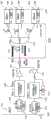
图3A示出了根据本公开的一个实施例的具有时间透镜处理器的D-K配置的对称PON架构。3A illustrates a symmetric PON architecture with a D-K configuration of a time lens processor according to one embodiment of the present disclosure.
图3B示出了根据本公开的一个实施例的具有时间透镜处理器的K-D-K配置的对称PON架构。3B illustrates a symmetric PON architecture with a K-D-K configuration of a time lens processor according to one embodiment of the present disclosure.
图4示出了根据本公开的一个实施例的对称PON架构。这种架构可以为下行传输和上行传输提供相同的总数据速率。Figure 4 illustrates a symmetric PON architecture according to one embodiment of the present disclosure. This architecture can provide the same total data rate for downstream and upstream transmissions.
图5示例了当前公开的在点对多点架构中TDM和WDM信号之间的转换原理。Figure 5 illustrates the currently disclosed principle of conversion between TDM and WDM signals in a point-to-multipoint architecture.
图6示例了如本文所公开的少数点对多点架构。6 illustrates a minority point-to-multipoint architecture as disclosed herein.
图7示出了用于少数点对多点架构的M波长TWDM TX阵列和RX阵列。Figure 7 shows an M-wavelength TWDM TX array and RX array for a minority point-to-multipoint architecture.
图8示出了可以在少数点对多点架构中应用的转换原理。Figure 8 shows a conversion principle that can be applied in a minority point-to-multipoint architecture.
图9示例了如本文所公开的不对称(少数)点对多点架构。Figure 9 illustrates an asymmetric (few) point-to-multipoint architecture as disclosed herein.
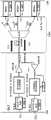
图10示出了使用时间透镜在150km 40-split的未放大光纤设备上使用40G P2MPPON的示例1的实验设置。Figure 10 shows the experimental setup of Example 1 using a 40G P2MPPON on a 150km 40-split unmagnified fiber plant using a time lens.
图11a示出了40Gb/s TDM CS-RZ-OOK信号的波形。Figure 11a shows the waveform of the 40Gb/s TDM CS-RZ-OOK signal.
图11b示出了OFT输出的频谱。Figure 11b shows the spectrum of the OFT output.
图11c示出了在功率均衡之后获得的40-信道WDM信号。Figure 11c shows a 40-channel WDM signal obtained after power equalization.
图12a示出了某些选定WDM信道的B2B BER性能。Figure 12a shows the B2B BER performance for some selected WDM channels.
图12b示出了150km SSMF传输前的所有信道BER性能。Figure 12b shows all channel BER performance before 150km SSMF transmission.
图12c示出了150km SSMF传输后的所有信道BER性能。Figure 12c shows all channel BER performance after 150km SSMF transmission.
图12d示出了传输前WDM第20号信道的波形。Figure 12d shows the waveform of WDM channel No. 20 before transmission.
图12e示出了传输后WDM第20号信道的波形。Figure 12e shows the waveform of WDM channel No. 20 after transmission.
图13a示出了20-信道WDM信号。Figure 13a shows a 20-channel WDM signal.
图13b示出了10-信道WDM信号的波长分配。Figure 13b shows the wavelength assignment of a 10-channel WDM signal.
图13c示出了设计的WDM信号。Figure 13c shows the designed WDM signal.
图13d示出了在OFT之前的TDM波形。Figure 13d shows the TDM waveform before OFT.
图13e示出了64×2Gb/s WDM频谱的转换频谱,以及100km之后的所有信道BER性能。Figure 13e shows the converted spectrum of the 64x2Gb/s WDM spectrum, and all channel BER performance after 100km.
图14示出了当前公开的点对多点架构中的TDM和WDM信号之间的转换原理的另一示例。Figure 14 shows another example of the principle of conversion between TDM and WDM signals in the currently disclosed point-to-multipoint architecture.
图15示出了当前公开的点对多点架构中的WDM和TDM信号之间的转换原理的另一示例。Figure 15 shows another example of the principle of conversion between WDM and TDM signals in the currently disclosed point-to-multipoint architecture.
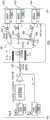
图16示出了在100km的未放大光纤设备上使用128×2Gb/s WDM PON的示例2中使用的实验设置。插图是绝缘体上AlGaAs(AIGaAs-on-insulator)波导的图片。Figure 16 shows the experimental setup used in Example 2 using a 128x2Gb/s WDM PON over 100km of unamplified fiber optic equipment. The inset is a picture of an AlGaAs-on-insulator waveguide.
图17A至17C示出了示例2中的实验结果,其比较了使用HNLF和绝缘体上AlGaAs波导在时间透镜中作为色散介质。图17A示出了OFT输出的频谱,图17B是闲频的放大图,图17C示出了对于B2B和100km传输,在-27dBm的固定接收功率下,所有128个WDM信道的AlGaAs和HNLF的误码率(BER)性能。Figures 17A to 17C show experimental results in Example 2 comparing the use of HNLF and AlGaAs-on-insulator waveguides as dispersive media in a time lens. Figure 17A shows the spectrum of the OFT output, Figure 17B is an enlarged view of the idler, and Figure 17C shows the error of AlGaAs and HNLF for all 128 WDM channels at a fixed received power of -27dBm for B2B and 100km transmission Bit rate (BER) performance.
具体实施方式Detailed ways
时间透镜信号处理单元包括色散介质和相位调制级,例如具有中间分散介质的两个相位调制级,即所谓的K-D-K配置。另一个示例是色散介质和单相调制级,即所谓的D-K或K-D配置。时间透镜信号处理阶段是光学傅立叶变换(OFT)的示例。例如在WO 2015/131908中公开了K-D-K配置。然而,当在本文所述的PON系统中采用时间透镜时,不能直接应用K-D-K配置。而是,在PON系统中采用时间透镜时,通常必须引入特定的操作参数和条件。The time-lens signal processing unit includes a dispersive medium and a phase modulation stage, eg two phase modulation stages with an intermediate dispersive medium, a so-called K-D-K configuration. Another example is dispersive media and single-phase modulation stages, so-called D-K or K-D configurations. The temporal lensing signal processing stage is an example of Optical Fourier Transform (OFT). A K-D-K configuration is disclosed, for example, in WO 2015/131908. However, the K-D-K configuration cannot be directly applied when time lensing is employed in the PON system described herein. Rather, when time lenses are employed in a PON system, certain operating parameters and conditions must generally be introduced.
时间透镜原理Time Lens Principle
正如空间光学成像系统可以生成大于或小于光学物体的图像一样,可以使用时间透镜压缩或扩展光脉冲。并且如先前所公开的,时间透镜可以扩展和压缩光脉冲,同时基本上保持脉冲的时域形廓。在US 5,453,871中公开了一种时间透镜,其中提出了一种脉冲压缩器,该脉冲压缩器以与光学成像系统的操作类似的方式对时域脉冲进行操作。Just as spatial optical imaging systems can generate images that are larger or smaller than optical objects, temporal lenses can be used to compress or expand light pulses. And as previously disclosed, a time lens can expand and compress an optical pulse while substantially maintaining the temporal profile of the pulse. A time lens is disclosed in US 5,453,871 in which a pulse compressor is proposed which operates on time domain pulses in a similar manner to the operation of optical imaging systems.
当前公开的OFT(时间透镜)模块中的相位调制可以通过各种方式来实现,例如通过例如使用啁啾泵浦脉冲的四波混频(FWM)。可以在非线性光学元件中获得四波混频(FWM),其中,使用啁啾泵浦脉冲对非线性光学元件进行光泵浦。非线性光学元件可以例如是高度非线性光纤(HNLF)。也可以通过使用抛物线强度形廓泵浦脉冲的交叉相位调制(XPM)或使用电驱动信号的电光相位调制来获得相位调制。FWM和XPM效果通常源自非线性光学Kerr效应,其通常用于非线性光信号处理。OFT单元中的色散介质可以通过标准光纤(例如标准单模光纤(SSMF)或色散补偿光纤(DCF))或高度非线性光纤或任何其他色散结构(例如绝缘体上硅波导平台)来实现。后者的一个示例是绝缘体上AlGaAs波导,例如,位于半导体衬底上的低折射率绝缘体层之上的薄AlxGa1-xAs层。晶片键合和衬底去除可用于实现该结构。铝分数(x)可以例如为17%,这使得材料带隙为1.63eV并且折射率为3.33。由于这种布局具有较大的折射率对比度(约55%),因此可以将光限制在亚微米波导芯中。如γ=2πn2/λAeff所示,由于非线性参数(γ)高度依赖于波导有效模式区域(Aeff),因此对于使用横截面尺寸为320nm×630nm的绝缘体上AlGaAs波导,可以获得比典型的Si3N4波导高几个数量级的约660W-1m-1的超高有效非线性[6,7]。Phase modulation in the presently disclosed OFT (time lensing) module can be achieved in various ways, such as by, for example, four-wave mixing (FWM) using chirped pump pulses. Four-wave mixing (FWM) can be obtained in nonlinear optical elements, where the nonlinear optical element is optically pumped using chirped pump pulses. The nonlinear optical element may be, for example, a highly nonlinear optical fiber (HNLF). Phase modulation can also be obtained by cross-phase modulation (XPM) of pump pulses using a parabolic intensity profile or electro-optic phase modulation using an electrical drive signal. FWM and XPM effects are often derived from the nonlinear optical Kerr effect, which is commonly used in nonlinear optical signal processing. The dispersive medium in the OFT cell can be realized by standard optical fibers (eg standard single mode fiber (SSMF) or dispersion compensating fiber (DCF)) or highly nonlinear fibers or any other dispersive structure (eg silicon-on-insulator waveguide platform). An example of the latter is an AlGaAs-on-insulator waveguide, eg, a thin AlxGa1-xAs layer over a low refractive index insulator layer on a semiconductor substrate. Wafer bonding and substrate removal can be used to achieve this structure. The aluminum fraction (x) may be, for example, 17%, which gives the material a band gap of 1.63 eV and a refractive index of 3.33. Since this layout has a large refractive index contrast (about 55%), it is possible to confine light in the submicron waveguide core. As the nonlinear parameter (γ) is highly dependent on the waveguide effective mode area (Aeff ), as shown by γ=2πn2 /λAeff , for using AlGaAs-on-insulator waveguides with cross-sectional dimensions of 320 nm × 630 nm, more than typical The Si3 N4 waveguide is several orders of magnitude higher with an ultra-high effective nonlinearity of about 660 W-1 m-1 [6,7].
光线路终端Optical Line Termination
如上所述,本公开的第一方面涉及一种用于无源光网络的光线路终端。光线路终端通常将包括至少一个发送器,例如用于生成时分多路复用(TDM)下行光数据信号。然后可以提供第一时间透镜光信号处理器,即OFT元件,并将其配置为将下行TDM信号转换为下行WDM信号,通常用于分配至多个用户。可以提供至少一个接收器,以用于接收和处理来自所述用户的上行信号。As mentioned above, a first aspect of the present disclosure relates to an optical line termination for a passive optical network. An optical line termination will typically include at least one transmitter, eg for generating a time division multiplexed (TDM) downstream optical data signal. A first time-lens optical signal processor, an OFT element, may then be provided and configured to convert downstream TDM signals to downstream WDM signals, typically for distribution to multiple users. At least one receiver may be provided for receiving and processing uplink signals from the users.
在另一个实施例中,可以提供第二时间透镜光信号处理器,并将其配置为将从所述用户接收的上行WDM信号转换为上行TDM信号。然后可以提供至少一个TDM接收器,以用于解复用和处理上行TDM信号。可替代地,可以提供至少一个WDM接收器,以用于对从所述用户接收的上行WDM信号进行解复用。In another embodiment, a second time-lens optical signal processor may be provided and configured to convert upstream WDM signals received from the user to upstream TDM signals. At least one TDM receiver may then be provided for demultiplexing and processing the upstream TDM signals. Alternatively, at least one WDM receiver may be provided for demultiplexing the upstream WDM signals received from the users.
可以提供诸如WDM耦合器的分光器,以将来自所述用户/ONU的上行信号与下行WDM信号分离。可以提供至少一个放大器,例如可以提供诸如EDFA的光放大器,以用于放大下行WDM信号和/或上行WDM信号。下行放大器可以看作是升压放大器,其可以在进入传输链路之前对WDM下行信号进行升压。如本文的示例1所示,可以获得具有150km的未放大传输距离的40G PON系统。同样,上行信号可以在传输链路之后和第二次透镜模块之前被升压,该第二次透镜模块将WDM信号转换为TDM信号。An optical splitter, such as a WDM coupler, may be provided to separate the upstream signal from the downstream WDM signal from the user/ONU. At least one amplifier may be provided, eg an optical amplifier such as an EDFA, for amplifying downstream WDM signals and/or upstream WDM signals. The downlink amplifier can be regarded as a boost amplifier, which can boost the WDM downlink signal before entering the transmission link. As shown in Example 1 herein, a 40G PON system with an unamplified transmission distance of 150km can be obtained. Likewise, the upstream signal can be boosted after the transmission link and before the second lens module, which converts the WDM signal to a TDM signal.
在本公开的一个实施例中,第一时间透镜光信号处理器和/或第二时间透镜光信号处理器包括两个相位调制级,优选地为二次相位调制级,其由色散介质以K-D-K配置分开。优选地,在色散介质中,在具有线性调频斜率K1的第一相调制级中,

在本公开的另一个实施例中,第一时间透镜光信号处理器包括色散D=β2L的色散介质,其后是调频斜率为K=1/D的相位调制元件,优选为二次相位调制元件。然后第二透镜光信号处理器有利地包括调频斜率为K=1/D的相位调制元件,优选为二次相位调制元件,其后是色散为D=β2L的色散介质。即用于TDM到WDM转换的D-K配置,以及优选地用于WDM到TDM转换的K-D配置。这样的配置可以简化时间透镜模块,例如,与K-D-K配置相比。不利之处可能是对系统容量有小损失。In another embodiment of the present disclosure, the first time lens optical signal processor includes a dispersive medium with dispersion D=β2 L, followed by a phase modulation element with a frequency modulation slope of K=1/D, preferably a quadratic phase modulation element. The second lens optical signal processor then advantageously comprises a phase modulation element with a frequency modulation slope of K=1/D, preferably a secondary phase modulation element, followed by a dispersive medium with a dispersion of D=β2L . Namely the DK configuration for TDM to WDM conversion, and preferably the KD configuration for WDM to TDM conversion. Such a configuration can simplify the time lens module, eg, compared to the KDK configuration. The downside may be a small loss of system capacity.
色散介质是一段光纤,例如传输光纤、例如标准单模光纤(SSMF),例如色散补偿光纤(DCF)以及例如高度非线性光纤。相位调制级可以包括一段高度非线性光纤。通常,相位调制可以例如基于例如使用啁啾泵浦脉冲的四波混频(FWM)、例如使用抛物线强度形廓泵浦脉冲的交叉相位调制(XPM),或者例如使用电驱动信号的电光相位调制。A dispersive medium is a length of fiber, such as a transmission fiber, such as a standard single-mode fiber (SSMF), such as a dispersion compensating fiber (DCF), and, for example, a highly nonlinear fiber. The phase modulation stage may comprise a length of highly nonlinear fiber. Typically, the phase modulation may be based, for example, on four-wave mixing (FWM) using chirped pump pulses, for example cross-phase modulation (XPM) using parabolic intensity profiled pump pulses, or electro-optic phase modulation, eg using electrical drive signals .
可以提供时钟恢复单元并将其配置为将第二时间透镜信号处理器同步到上行WDM信号。此外,上行WDM信号的单个信道可以有利地在第二时间透镜光信号处理器的输入处以符号方式同步。可以提供至少一个控制单元并将其连接到发送器和/或接收器并且被配置为控制信号的波长和时序。A clock recovery unit may be provided and configured to synchronize the second time lens signal processor to the upstream WDM signal. Furthermore, the individual channels of the upstream WDM signal can advantageously be synchronized symbolically at the input of the second time lens optical signal processor. At least one control unit may be provided and connected to the transmitter and/or receiver and configured to control the wavelength and timing of the signals.
在少数点对多点架构中,发送器可以包括多波长时分波分多路复用(TWDM)阵列,该阵列被配置为在M个不同波长处生成时分多路复用下行光信号,其中M小于下行WDM信号中的信号波长的数量N。相应地,接收器可以包括多波长时分波分多路复用(TWDM)阵列,该阵列被配置为接收和处理M个不同波长处的时分多路复用上行光信号。In a minority point-to-multipoint architecture, the transmitter may include a multi-wavelength time division wavelength division multiplexing (TWDM) array configured to generate time division multiplexed downstream optical signals at M different wavelengths, where M Less than the number N of signal wavelengths in the downstream WDM signal. Accordingly, the receiver may comprise a multi-wavelength time division wavelength division multiplexing (TWDM) array configured to receive and process time division multiplexed upstream optical signals at M different wavelengths.
在非对称(少数)点对多点架构中,可以有利地简化接收器并将其配置为接收和处理单个波长处的时分多路复用上行光信号。In an asymmetric (few) point-to-multipoint architecture, the receiver can be advantageously simplified and configured to receive and process time division multiplexed upstream optical signals at a single wavelength.
无源光网络系统Passive Optical Network System
本公开的另一方面涉及一种包括本文所述的光线路终端的无源光网络(PON)系统。PON系统通常包括用于分配下行信号和上行信号的光纤基础设施。通常还至少有一个用于将下行WDM信号分离成单独的波长信号的远程节点,通常是无源远程节点,即没有电源,例如无源AWG。然后可以将至少一个远程节点配置为将上行单独的波长信号组合成上行WDM信号。远程节点可以包括至少一个阵列波导光栅(AWG),以用于将下行WDM信号分成单独的波长信号和/或用于将上行信号组合成单个WDM上行信号或TDM上行信号。Another aspect of the present disclosure relates to a passive optical network (PON) system including the optical line terminal described herein. PON systems typically include fiber optic infrastructure for distributing downstream and upstream signals. There is also usually at least one remote node for splitting the downstream WDM signal into separate wavelength signals, usually a passive remote node, ie without a power source, eg a passive AWG. The at least one remote node can then be configured to combine the upstream separate wavelength signals into an upstream WDM signal. The remote node may include at least one arrayed waveguide grating (AWG) for splitting downstream WDM signals into separate wavelength signals and/or for combining upstream signals into a single WDM upstream signal or TDM upstream signal.
在对称的点对多点或少数点对多点架构中,当前公开的PON系统还可以包括位于每个用户处并被配置为生成单独的波长上行信号的单独的ONU发送器,该单独的上行波长信号可以被组合为单个(或少数)上行W DM信号。In a symmetric point-to-multipoint or few point-to-multipoint architecture, the presently disclosed PON system may also include a separate ONU transmitter located at each user and configured to generate a separate wavelength upstream signal, the separate upstream The wavelength signals can be combined into a single (or few) upstream WDM signals.
在非对称点对多点或少数点对多点架构中,当前公开的PON系统还可以包括位于每个用户处的单独的ONU发送器,其被配置为生成一个预定波长处的上行信号,该上行信号可以被组合成单个(或少数)上行TDM信号。在那种情况下,在(一个或多个)远程节点与单独的ONU之间的每条网络线可以包括分路器,例如WDM耦合器,以用于将所述预定波长处的上行信号与下行单独的波长信号分离。In an asymmetric point-to-multipoint or minority point-to-multipoint architecture, the presently disclosed PON system may also include a separate ONU transmitter at each user configured to generate an upstream signal at a predetermined wavelength that The upstream signals may be combined into a single (or few) upstream TDM signals. In that case, each network line between the remote node(s) and an individual ONU may include a splitter, such as a WDM coupler, for splitting the upstream signal at the predetermined wavelength with the Downlink separate wavelength signal separation.
对称点对多点Symmetric point-to-multipoint
图3A、图3B和图4示出了对称点对多点架构的示例。在图4的下行数据传输中使用了以下符号:Figures 3A, 3B and 4 illustrate examples of symmetrical point-to-multipoint architectures. The following symbols are used in the downstream data transmission of Figure 4:
OLT(光线路终端):PON头端,通常位于中心局中OLT (Optical Line Terminal): PON head end, usually located in the central office
ONU(光网络单元):用户侧PON设备ONU (Optical Network Unit): user-side PON equipment
ODN(光分配网络):将OLT连接到ONU的光纤基础设施ODN (Optical Distribution Network): Optical fiber infrastructure that connects OLTs to ONUs
SNI(服务节点接口):到城域/核心网的接口SNI (Service Node Interface): Interface to Metro/Core Network
UNI(用户网络接口):与用户网络的接口UNI (User Network Interface): The interface to the user network
CR(时钟恢复):同步光信号处理器2。CR (Clock Recovery): Synchronizes the
数据信号从OLT(101)发送到N个ONU(102、103、104)。TDM发送器(105)生成具有符号率fs的单波长高速TDM光数据信号(201)。使用基于时间透镜的光信号处理器(106)将TDM光数据信号转换为具有信道间隔Δν的N-波长(λ1,λ2,…,λn)WDM信号(202)。转换后的N-波长WDM信号在光放大器(107)中被放大,并进一步发送到WDM耦合器(108)中,该WDM耦合器用于分离OLT中的下行信号和上行信号。单股光纤(109)用于将WDM信号从OLT传输到靠近ONU的远程节点(RN)位置。在RN位置处,波长信道间隔为Δν的无源周期性阵列波导光栅(AWG)(110)用于将WDM信号分配到每个ONU上。Data signals are sent from the OLT (101) to N ONUs (102, 103, 104). The TDM transmitter (105) generates a single wavelength high speed TDM optical data signal (201) with a symbol ratefs . The TDM optical data signal is converted to anN -wavelength (λ1 , λ2 , . The converted N-wavelength WDM signal is amplified in an optical amplifier (107) and further sent to a WDM coupler (108) which is used to separate downstream and upstream signals in the OLT. A single strand of fiber (109) is used to transmit the WDM signal from the OLT to a remote node (RN) location close to the ONU. At the RN location, a passive periodic arrayed waveguide grating (AWG) (110) with wavelength channel spacing of Δν is used to distribute the WDM signal to each ONU.
图5示出并示例了通过时间透镜信号处理器(203)的TDM(201)到N-波长WDM信号(202)的转换,反之亦然。在此,ΔT是TDM信号的符号时间间隔,Δν是转换后的WDM信号的WDM信道间隔。用于TDM到WDM转换的时间透镜光信号处理器包括具有线性调频斜率K的两个二次相位调制(PM)
在上行数据传输中,每个ONU(102、103、104)处的发送器会生成单独的特定波长WDM信道(λu1,λu2,…,λuN),其匹配根据λuN=λN+Δλ在不同波长区域处的周期性AWG(110)的传输窗口。单独的WDM信道在AWG处被组合为N-波长WDM信号,并通过同一光纤(109)在不同波长区域处被传输回OLT。在OLT中,使用WDM耦合器(108)将上行WDM信号切换到上行RX。在预放大(111)之后,使用另一个基于时间透镜的光信号处理器2将WDM信号转换为TDM信号(112)。图5还示出了通过光信号处理器2(112)的N波长WDM(202)到TDM信号(201)的转换。光信号处理器1(106)和2(112)中的组件和设置基本相同。时钟恢复单元(113)用于将时间透镜信号处理器2(112)与WDM信号同步。最终,转换后的TDM信号被单个TDM接收器接收(114)。请注意,对于WDM到TDM的转换,通常需要在时间透镜处理器(112)的输入处以符号方式同步WDM信道,控制单元(115、116)被用于控制OLT侧和ONU侧中的信号的波长和时序。此外,通过在OLT中使用光时分多路复用(OTDM),可以进一步增加总的时间透镜PON容量。In upstream data transmission, the transmitter at each ONU (102, 103, 104) generates a separate wavelength-specific WDM channel (λu1 ,λu2 ,...,λuN ), which is matched according to λuN =λN + Δλ Transmission window of a periodic AWG (110) at different wavelength regions. The individual WDM channels are combined into N-wavelength WDM signals at the AWG and transmitted back to the OLT at different wavelength regions through the same fiber (109). In the OLT, a WDM coupler (108) is used to switch the upstream WDM signal to the upstream RX. After pre-amplification (111), another time-lens based
如前所述,可以将时间透镜光信号处理器从K-D-K简化为D-K配置,以进行TDM到WDM的下行转换,如图14中所示。在图14中,通过使第一相位调制级K1几乎不可见来示出。在D-K下行配置的情况下,可能有必要在时域中添加足够量的保护间隔(GI),如图14左侧所示。保护间隔的量与信号带宽Δλ、色散D和PM窗口之间的间隙Tg有关,根据:As mentioned earlier, the time lens optical signal processor can be simplified from a KDK to a DK configuration for TDM to WDM down-conversion, as shown in Figure 14. In Figure 14 this is shown by making thefirst phase modulation stage K1 barely visible. In the case of a DK downstream configuration, it may be necessary to add a sufficient amount of guard interval (GI) in the time domain, as shown on the left side of Figure 14. The amount of guard interval is related to the signal bandwidth Δλ, the dispersion D, and the gap Tg between the PM windows, according to:

其中c是光速,λ是信号波长。在大约1530nm至大约1565nm的C波段中,该公式可以写为:where c is the speed of light and λ is the signal wavelength. In the C-band from about 1530nm to about 1565nm, the formula can be written as:
GI≥0.78DΔλ+TgGI≥0.78DΔλ+Tg
即,当按照二次相位调制的重复频率fPM周期性地向信号提供足够的保护间隔时,可以省略第一二次相位调制级,如图14所示。但是,增加保护间隔自然会减少系统的数据容量。即这成为成本和数据容量之间的平衡。That is, when a sufficient guard interval is periodically provided to the signal according to the repetition frequency fPM of the secondary phase modulation, the first secondary phase modulation stage can be omitted, as shown in FIG. 14 . However, increasing the guard interval naturally reduces the data capacity of the system. That is, it becomes a balance between cost and data capacity.
对于WDM到TDM转换的上行,还可以简化K-D-K配置,在这种情况下,可以简化为图15中所示的K-D配置。与下行D-K配置的保护间隔相比,上行K-D配置没有限制,因此可以省略K1。For the upstream of WDM to TDM conversion, the KDK configuration can also be simplified, in this case, the KD configuration shown in Figure 15 can be simplified. Compared with the guard interval of the downstream DK configuration, the upstream KD configuration is not limited, so K1 can be omitted.
对称少数点对多点Symmetric Minority-to-Many
如图6所示,点对多点架构的容量可以通过所谓的对称少数点对多点架构来被进一步增加。以上公开的从对称点到多点时间透镜PON架构的主要区别在于,OLT中的单波长TDM TX和RX被具有多个M波长的多波长TWDM TX阵列(301)和RX阵列(302)代替。但是,波长数M通常比ONU数N小得多。这种少数点对多点架构可以通过简单地在OLT中的不同波长处添加TDM TRX来将总时间透镜PON容量增加系数M。图7中示例了M波长TWDM TX阵列和RX阵列。在ONU侧,单个ONU在原始波长处获得增加的比特率,而无需WDM TRX阵列。As shown in Figure 6, the capacity of a point-to-multipoint architecture can be further increased by a so-called symmetric minority point-to-multipoint architecture. The main difference from the symmetrical point-to-multipoint time lensed PON architecture disclosed above is that the single wavelength TDM TX and RX in the OLT are replaced by a multi-wavelength TWDM TX array (301) and RX array (302) with multiple M wavelengths. However, the number M of wavelengths is usually much smaller than the number N of ONUs. This minority point-to-multipoint architecture can increase the total time-lens PON capacity by a factor M by simply adding TDM TRXs at different wavelengths in the OLT. The M-wavelength TWDM TX array and RX array are illustrated in FIG. 7 . On the ONU side, a single ONU gets the increased bit rate at the original wavelength without the need for a WDM TRX array.
图8示出了通过时间透镜信号处理器(503)的M-波长TWDM(501)到N-波长WDM信号(502)(M到N)的转换,反之亦然(N到M转换)。对于M-TWDM到N-WDM的转换,TWDM信号的符号率是fs,二次相位调制的重复频率fPM被设置为fs/N。根据K的选择,将M-波长TWDM信号转换为信道间隔为ΔνN的N-波长WDM信号,其也确定了M-TWDM信道间隔为ΔνM。每个转换的WDM信道的符号率均被M复用,即Mfs/N。M-TWDM到N-WDM以及N-WDM到M-TWDM的组件和设置都可以基本相同。Figure 8 shows the conversion of an M-wavelength TWDM (501) to an N-wavelength WDM signal (502) (M to N) and vice versa (N to M conversion) by a time lensed signal processor (503). For M-TWDM to N-WDM conversion, the symbol rate of the TWDM signal is fs and the repetition frequency fPM of the secondary phase modulation is set to fs /N. Depending on the choice of K, the M-wavelength TWDM signal is converted to anN -wavelength WDM signal with a channel spacing of ΔνN, which also defines theM -TWDM channel spacing as ΔνM. The symbol rate of each converted WDM channel is multiplexed by M, ie Mfs /N. Both M-TWDM to N-WDM and N-WDM to M-TWDM components and settings can be substantially the same.
非对称点对多点和少数点对多点Asymmetric point-to-multipoint and minority point-to-multipoint
某些接入网要求用于下行传输的容量大于用于上行传输的容量。在那种情况下,总上行数据速率小于下行数据速率的非对称PON体系结构可能是合适的。图9示出了一个示例。该实施例将时间透镜PON和传统的TDM PON相结合,其中时间透镜PON架构用于高容量需求的下行传输,而传统的TDM PON用于需求较少的上行传输。如上所述,下行部分可以类似于对称点对多点和少数点对多点。ODN中的AWG(601)具有N+1个端口,其中端口1到N用于下行传输,而最后一个端口(N+1)仅用于上行传输。在上行部分,每个ONU(602、603、604)处的发送器在相同的λu处生成TDM信道,该信道与根据λuN+1=λN+1+Δλ的不同波长区域处的周期AWG端口第N+1号的传输窗口匹配。在远程节点(RN)位置处,上行信号由N个WDM耦合器(605)分离,并由N对1光学组合器(606)组合到AWG端口第N+1号。TDM信号通过同一根光纤在λuN+1处被传输回到OLT。在OLT中,使用WDM耦合器将上行TDM信号切换到上行RX(607)。Some access networks require more capacity for downstream transmission than for upstream transmission. In that case, an asymmetric PON architecture where the overall upstream data rate is less than the downstream data rate may be appropriate. Figure 9 shows an example. This embodiment combines a time-lens PON with a traditional TDM PON, where the time-lens PON architecture is used for downstream transmissions with high capacity requirements, while the traditional TDM PON is used for upstream transmissions with less demand. As mentioned above, the downstream portion can be similar to symmetric point-to-multipoint and minority point-to-multipoint. The AWG (601) in the ODN has N+1 ports, where
时间透镜PON的优势Advantages of Time Lens PON
图1示出了现有技术的光接入系统的四个示例a)至d),其中c)和d)示出了PON系统。图1(a)是需要大量光纤和发送器的点对点系统。图1(b)示出了需要大量发送器的有源光网络。图1(c)是TDM-PON系统的示例,TDM-PON系统是经济高效的解决方案,因为在中心局(CO)中只需要一个发送器即可。TDM-PON原理在图2A中被进一步详细说明。图1(d)所示的WDM-PON系统是具有许多技术优势的点对点系统,但这不是一种具有成本效益的解决方案。WDM-PON原理在图2B中被进一步详细说明。与这些现有技术解决方案相比,时间透镜PON具有许多优点:Figure 1 shows four examples a) to d) of prior art optical access systems, where c) and d) show a PON system. Figure 1(a) is a point-to-point system that requires a large number of fibers and transmitters. Figure 1(b) shows an active optical network requiring a large number of transmitters. Figure 1(c) is an example of a TDM-PON system, which is a cost-effective solution because only one transmitter is required in the central office (CO). The TDM-PON principle is further detailed in Figure 2A. The WDM-PON system shown in Figure 1(d) is a point-to-point system with many technical advantages, but it is not a cost-effective solution. The WDM-PON principle is further detailed in Figure 2B. Compared to these prior art solutions, time lensed PONs offer many advantages:
中心局(CO)中的一个(或少数)发送器:成本和能耗更低,即,在时间透镜PON中保留了现有TDM PON的优势之一。One (or few) transmitters in the central office (CO): Lower cost and energy consumption, ie one of the advantages of existing TDM PONs is preserved in the Time Lens PON.
分路损耗很小,并且与用户数量无关:在常规PON系统中,无源分光器/组合器的使用会根据用户数量N引入约10LogN[dB]的分路损耗,这严重限制了用户数量。与此相反,在时间透镜PON中,无论用户数量如何,都可以用例如具有低得多的固定损耗(<4dB)的常规的无源AWG替换分光器,这允许有效扩大用户数量。The shunt loss is small and independent of the number of users: In conventional PON systems, the use of passive splitters/combiners introduces a shunt loss of about 10LogN[dB] depending on the number of users N, which severely limits the number of users. In contrast, in a time-lens PON, regardless of the number of users, the optical splitter can be replaced by eg a conventional passive AWG with much lower fixed losses (<4dB), which allows for an efficient expansion of the number of users.
没有取决于用户数量N的SNR损失:在常规PON系统中,OLT将TDM信号广播给所有ONU。因此,实际信号功率仅为每个ONU处的总接收功率的1/N。较大的集成噪声带宽也会带来噪声。这导致正比于N2~N3的SNR损失。与此相反,每个ONU在时间透镜PON中仅在基本带宽处接收其自身的信号。因此,在时间透镜PON中不存在取决于用户数量的SNR损失,从而导致更好的接收器灵敏度,例如,比具有32个用户的现有技术TDM-PON好约10dB。There is no SNR penalty depending on the number of users N: In a conventional PON system, the OLT broadcasts the TDM signal to all ONUs. Therefore, the actual signal power is only 1/N of the total received power at each ONU. The larger integrated noise bandwidth also contributes to noise. This results in an SNR loss proportional toN2- N3. In contrast, each ONU only receives its own signal at the fundamental bandwidth in the time lens PON. Therefore, there is no SNR loss depending on the number of users in the time lens PON, resulting in better receiver sensitivity, eg, about 10 dB better than the prior art TDM-PON with 32 users.
更好的功率预算:与现有技术PON相比,减少的分路损耗和更好的接收器灵敏度导致时间透镜PON的功率预算更大。此外,提高的功率预算与用户数量无关。增强的功率预算可用于有效地扩展总容量、用户数量和传输范围。Better power budget: The reduced split loss and better receiver sensitivity result in a larger power budget for the Time Lens PON compared to prior art PONs. Furthermore, the increased power budget is independent of the number of users. The enhanced power budget can be used to effectively expand the total capacity, number of users and transmission range.
对ONU侧的组件没有额外的带宽要求:在常规PON系统中,ONU侧的收发器要求的带宽是实际使用的数据速率的数十倍。这种系统的升级需要用于所有ONU的大量具有更高带宽的光电装置,这是昂贵的,并导致更高的能耗。在当前公开的时间透镜PON中,不存在额外的带宽需求,从而允许ONU侧上的现有设备的重复使用数十倍的数据容量,这比其他现有技术的高容量PON解决方案具有更高的成本效率和能量效率。No additional bandwidth requirements for components on the ONU side: In conventional PON systems, the bandwidth required by the transceivers on the ONU side is tens of times the actual data rate used. The upgrade of such a system requires a large number of optoelectronic devices with higher bandwidth for all ONUs, which is expensive and leads to higher energy consumption. In the presently disclosed Time Lens PON, there is no additional bandwidth requirement, allowing reuse of existing equipment on the ONU side for tens of times the data capacity, which is higher than other prior art high capacity PON solutions cost and energy efficiency.
没有安全问题:现有技术PON系统需要数据加密,因为每个ONU都可以访问发送给PON上其他任何用户的所有数据。在当前公开的时间透镜PON中,RN处的波长解复用器(例如,AWG)将不同的波长指向每个用户。因此,由于时间透镜PON上的用户无法访问任何其他下行波长,因此没有安全问题。因此,物理网络的架构保证了安全性。No security concerns: prior art PON systems require data encryption because each ONU has access to all data sent to any other user on the PON. In the presently disclosed time-lensed PON, a wavelength demultiplexer (eg, AWG) at the RN directs a different wavelength to each user. Therefore, there are no security concerns as users on the Time Lens PON cannot access any other downstream wavelengths. Therefore, the architecture of the physical network guarantees security.
色散容限:传统的PON系统在光纤链路中传输高速TDM信号,色散容限较差,随着TDM信号速度的提高,色散容限将越来越差。当前公开的时间透镜PON在光纤链路中传输低速WDM信号,其具有比现有技术PON系统更好的色散容限。Dispersion tolerance: The traditional PON system transmits high-speed TDM signals in optical fiber links, and the dispersion tolerance is poor. As the speed of the TDM signal increases, the dispersion tolerance will become worse and worse. The presently disclosed time-lensed PON transmits low-speed WDM signals in fiber optic links with better dispersion tolerance than prior art PON systems.
没有与共享PON相关的服务质量(QoS)问题:当现有技术PON系统中的带宽需求变高时,可能会导致QoS问题,例如:如何公平地将容量分配给多个高需求用户。这可能导致要求等待发送数据的用户使用更大的缓冲存储器,以及有关时间延迟和数据包丢失的问题。在当前公开的时间透镜PON中,关于QoS或保密性没有问题,因为不与连接到时间透镜PON的任何其他人共享光信号。即使在网络高峰时段,也可以保证用户体验。No quality of service (QoS) issues associated with shared PONs: When bandwidth demands in prior art PON systems become high, QoS issues may arise, such as how to fairly distribute capacity to multiple high-demand users. This can lead to larger buffer memory requirements for users waiting to send data, as well as problems with time delays and packet loss. In the presently disclosed Time Lens PON, there is no problem with regard to QoS or privacy, since the optical signal is not shared with anyone else connected to the Time Lens PON. User experience is guaranteed even during peak network hours.
上面列出的优点可以总结如下:The advantages listed above can be summarized as follows:


示例1Example 1
目前公开的时间透镜PON方法已通过实验证明。使用单载波OOK发送器和低成本的基于10GHz APD的接收器,可以在150-km 40-split的未放大的SMF设备上实现40Gbit/sPON下行传输,从而在BER=3x10-6的情况下实现了51.5dB(35.5dB/ch)的功率预算,同时,同一系统使用光学TDM技术在100km 64split的未放大光纤设备上实现了128Gb/s PON,在波长控制和系统容量方面显示了本发明方案的灵活性和可扩展性。The currently disclosed time-lens PON method has been experimentally proven. Using single-carrier OOK transmitters and low-cost 10GHz APD-based receivers, 40Gbit/sPON downstream transmission can be achieved over a 150-km 40-split unamplified SMF device, resulting in a BER=3x10⁻⁶ The power budget of 51.5dB (35.5dB/ch) is achieved. At the same time, the same system uses optical TDM technology to realize 128Gb/s PON on 100km 64split unamplified fiber equipment, which shows the advantages of the scheme of the present invention in terms of wavelength control and system capacity. Flexibility and scalability.
原理与实验设置Principle and experimental setup
在图3A中示出了当前公开的OLT结构/PON架构的一个示例,并且在此示例1中使用了该设置。在光线路终端(OLT)中,单载波TDM发送器生成高速TDM信号,然后,使用基于时间透镜的OFT信号处理器将其转换为多个低速WDM信道,该OFT信号处理器包括色散D=β2L的色散介质,然后是调频斜率为K=1/D的二次相位调制。转换后的WDM信号通过基于波长分路器的外部设备进行传输,例如使用阵列波导光栅(AWG)。在ONU侧,每个ONU使用低速组件接收自己的特定波长信道。与通过基于功率分配器的外部设备传输高速TDM信号不同,建议的OLT结构继承了WDM-PON的先进技术,例如更高的色散容限、更低的分路损耗、更好的接收器灵敏度、更长的覆盖范围、安全性和有保证的服务质量,但在OLT处仅需一个发送器,提供了更大的灵活性和可扩展性。An example of the presently disclosed OLT architecture/PON architecture is shown in Figure 3A, and this setup is used in this Example 1. In an Optical Line Terminal (OLT), a single-carrier TDM transmitter generates a high-speed TDM signal, which is then converted to multiple low-speed WDM channels using a time-lens-based OFT signal processor that includes dispersion D = β A dispersive medium of2 L, followed by a secondary phase modulation with a frequency modulation slope of K=1/D. The converted WDM signal is transmitted through a wavelength splitter-based external device, such as using an arrayed waveguide grating (AWG). On the ONU side, each ONU uses low-speed components to receive its own wavelength-specific channel. Unlike the transmission of high-speed TDM signals through power divider-based external devices, the proposed OLT structure inherits the advanced technologies of WDM-PON, such as higher dispersion tolerance, lower shunt loss, better receiver sensitivity, Longer coverage, security and guaranteed quality of service, but requires only one transmitter at the OLT, providing greater flexibility and scalability.
实验设置如图10所示。在1581.5nm处的外腔CW激光器的输出是在Mach-Zehnder调制器(MZM)中调制的NRZ开-关键控(OOK)。用于调制的数据模式由40x1-Gb/s 211-1PRBS TDM支路和用于OFT操作的每40个TDM支路之间的200-ps保护间隔(GI)组成。第二个MZM用于将NRZ信号分解为载波抑制的归零(CS-RZ)信号,从而生成具有保护间隔的40Gb/s CSRZ OOK信号,如图11(a)所示,可以使用OFT将其直接转换为单个WDM信道,而无需任何进一步的光学滤波。在OFT处,首先将获得的40Gb/s TDM信号色散在470m色散补偿光纤(DCF)中。二次相位调制基于在高度非线性光纤(HNLF)中使用线性啁啾泵浦脉冲的四波混频(FWM)过程实现。泵浦脉冲源是1542nm处的10GHz锁模激光器(MLL),其在400m HNLF中光谱地加宽。MZM用于将MLL的重复率降低到1GHz,以使OFT能够在1GHz下运行。通过在波长选择开关(WSS3)中对加宽的光谱进行滤波并在1.1km的色散补偿光纤(DCF)中传播来获得OFT泵浦。设置调频斜率K=0.014ps-2,以将20ps的时间间隔转换为46GHz频率网格。所得光谱如图11(b)所示。生成的空闲信号是从40Gb/s TDM信号转换而来的40信道WDM信号。用光学带通滤波器提取后,在WSS1中均衡生成的WDM信道的功率电平。功率均衡后的40信道WDM信号的频谱如图11(c)所示,其中观察到具有46GHz间隔的40个1-Gb/s WDM信道。使用掺铒光纤放大器(EDFA)将获得的WDM信号光学增强到21.5dBm(5.5dBm/ch),并发射到150km的未放大SMF光纤链路中。波长分路器由另一个WSS实现。在ONU中,每个分裂的WDM信道都由低成本的基于10GHzAPD/TIA的接收器直接接收。The experimental setup is shown in Figure 10. The output of the external cavity CW laser at 1581.5 nm is NRZ On-Keying (OOK) modulated in a Mach-Zehnder Modulator (MZM). The data pattern used for modulation consists of 40x1-Gb/s 211 -1 PRBS TDM tributaries and a 200-ps guard interval (GI) between every 40 TDM tributaries for OFT operation. The second MZM is used to decompose the NRZ signal into a carrier suppressed return-to-zero (CS-RZ) signal, resulting in a 40Gb/s CSRZ OOK signal with a guard interval, as shown in Figure 11(a), which can be split using OFT Convert directly to a single WDM channel without any further optical filtering. At the OFT, the obtained 40Gb/s TDM signal is first dispersed in a 470m dispersion compensating fiber (DCF). Secondary phase modulation is achieved based on a four-wave mixing (FWM) process using linearly chirped pump pulses in a highly nonlinear fiber (HNLF). The pump pulse source was a 10 GHz mode-locked laser (MLL) at 1542 nm, spectrally broadened in 400 m HNLF. MZM is used to reduce the repetition rate of MLL to 1GHz to enable OFT to operate at 1GHz. OFT pumping was obtained by filtering the broadened spectrum in a wavelength selective switch (WSS3) and propagating in a 1.1 km dispersion compensating fiber (DCF). Set the FM slope K = 0.014ps-2 to convert the 20ps time interval to a 46GHz frequency grid. The resulting spectrum is shown in Figure 11(b). The generated idle signal is a 40-channel WDM signal converted from a 40Gb/s TDM signal. After extraction with an optical bandpass filter, the power levels of the resulting WDM channels are equalized in WSS1. The spectrum of the 40-channel WDM signal after power equalization is shown in Fig. 11(c), where 40 1-Gb/s WDM channels with 46 GHz spacing are observed. The obtained WDM signal was optically enhanced to 21.5dBm (5.5dBm/ch) using an erbium-doped fiber amplifier (EDFA) and launched into a 150km unamplified SMF fiber link. The wavelength splitter is implemented by another WSS. In the ONU, each split WDM channel is directly received by a low-cost 10GHz APD/TIA-based receiver.
实验结果Experimental results
图12(a)示出了在TDM到WDM转换后,某些选定的1-Gb/s RZ-OOK WDM信道的背对背(B2B)BER性能。作为参考,还示出了使用相同APD的10-Gb/s NRZ-OOK基线BER曲线。当接收较低符号率的RZ信号时,从基于APD的接收器在BER=10-9处获得11dB的更好接收器灵敏度。图4(b)示出了在以-35dBm的固定接收功率进行传输之前,所有40个WDM信道的BER性能,而图12(c)示出了在150km传输后未进行-30dBm的重新放大或色散补偿的BER性能。在150km传输之后,所有转换后的WDM信道均达到BER<3x10⁻⁶,即远低于BER=10-3的前向纠错(FEC)阈值,表明在错误更正之后的所有WDM信道均可实现10-12的BER。WDM信道之间的BER波动在传输之前和之后都可以观察到,这是由于由TDM信号的符号间干扰在OFT处引起的信道间干扰(ICI)。边缘信道的BER由于ICI较少而更好。150km传输后的功率损失为约7dB。这是由于传输过程中的光纤非线性和色散,这可以从WDM信道之前的波形观察到,请参见图12(d),以及在传输后,请参见图12(e)。150km传输后BER=3x10⁻⁶时,功率预算为51.5dB(35.5dB/ch)。Figure 12(a) shows the back-to-back (B2B) BER performance for some selected 1-Gb/s RZ-OOK WDM channels after TDM-to-WDM conversion. For reference, the 10-Gb/s NRZ-OOK baseline BER curve using the same APD is also shown. A better receiver sensitivity of 11 dB is obtained from the APD based receiver at BER=10−9 when receiving lower symbol rate RZ signals. Figure 4(b) shows the BER performance of all 40 WDM channels before transmission at a fixed received power of -35dBm, while Figure 12(c) shows no re-amplification or -30dBm after 150km transmission or Dispersion compensated BER performance. After 150km transmission, all converted WDM channels achieve BER<3x10⁻⁶ , which is well below the forward error correction (FEC) threshold of BER=10-3 , indicating that all WDM channels after error correction are achievable BER of10-12 . BER fluctuations between WDM channels can be observed both before and after transmission due to inter-channel interference (ICI) at OFT caused by inter-symbol interference of TDM signals. The BER of the edge channel is better due to less ICI. The power loss after 150km transmission is about 7dB. This is due to fiber nonlinearity and dispersion during transmission, which can be observed from the waveforms before the WDM channel, see Fig. 12(d), and after transmission, see Fig. 12(e). When BER=3x10⁻⁶ after 150km transmission, the power budget is 51.5dB (35.5dB/ch).
灵活性和可扩展性Flexibility and Scalability
提议的OLT结构/PON体系结构在波长分配方面具有高度的灵活性,因为OFT允许通过在时域中编码(重新映射)TDM信号来以亚纳秒为单位调节信号波长,而无需调节光源的实际波长。如图13所示,通过OFT和TDM信号编码,可以通过关闭每两个TDM支路来实现间隔为92GHz的20-信道WDM信号(图13(a))。图13(b)示出了使用OFT的10-信道WDM信号的波长分配,这可以降低WDM信道到AWG端口的波长对准的复杂性。图13(c)示出了设计的OFT输出,该输出是通过对如图13(d)所示的TDM信号进行编码而获得的,表明该提出的方案在WDM信道数量、信道间隔及其波长分配方面具有很高的灵活性。此外,使用光学TDM技术,该系统还用于在100km 64split的未放大光纤设备上实现128Gb/s PON。OTDM发送器的设置如图10所示,其中MLL的输出是使用基于光纤延迟线的OTDM多路复用器将OOK数据调制为8Gb/s,然后将OTDM调制为128Gb/s。具有37GHz频率网格的经OFT转换的64×2Gb/s WDM信号的频谱以及100km之后的所有信道BER性能如图13(e)所示,其中所有转换的WDM信道均达到BER<5x10⁻⁶,示出了目前公开原理的灵活性和可扩展性。The proposed OLT structure/PON architecture is highly flexible in terms of wavelength assignment, as OFT allows sub-nanosecond modulation of the signal wavelength by encoding (remapping) the TDM signal in the time domain, without adjusting the actual light source. wavelength. As shown in Fig. 13, through OFT and TDM signal encoding, a 20-channel WDM signal with an interval of 92 GHz can be achieved by closing every two TDM branches (Fig. 13(a)). Figure 13(b) shows wavelength assignment of a 10-channel WDM signal using OFT, which can reduce the complexity of wavelength alignment of WDM channels to AWG ports. Figure 13(c) shows the designed OFT output, which is obtained by encoding the TDM signal as shown in There is a high degree of flexibility in allocation. In addition, using optical TDM technology, the system is also used to implement 128Gb/s PON over 100km 64split unamplified fiber equipment. The setup of the OTDM transmitter is shown in Figure 10, where the output of the MLL is to modulate the OOK data to 8Gb/s using an optical fiber delay line based OTDM multiplexer, and then modulate the OTDM to 128Gb/s. The spectrum of OFT-converted 64×2Gb/s WDM signal with 37GHz frequency grid and all channel BER performance after 100km are shown in Fig. 13(e), where all converted WDM channels achieve BER<5x10⁻⁶ , The flexibility and extensibility of the presently disclosed principles is shown.
因此,已经通过实验验证了使用OFT的WDM-PON的高度灵活和可扩展的OLT结构。使用单个OOK发送器和低成本的基于10-GHz APD的接收器,成功演示了在150km 40split的未放大的光纤设备上进行的长距离40Gb/s PON传输。Therefore, the highly flexible and scalable OLT structure of WDM-PON using OFT has been experimentally verified. Using a single OOK transmitter and a low-cost 10-GHz APD-based receiver, long-distance 40Gb/s PON transmission over 150km 40split unamplified fiber optic equipment was successfully demonstrated.
示例2Example 2
在该示例中,研究了当前公开解决方案的可扩展性,并使用200m高非线性光纤(例如,来自OFS的HNLF)演示了在100-km的未放大SMF设备上进行的128×2Gb/s WDM PON下行传输。尽管所有128个生成的WDM信道在传输后都达到了低于10-3前向纠错(FEC)限制的BER,但是可以观察到HNLF的带宽限制,这将限制所提出方案的可扩展性。为了克服这个问题,研究了使用绝缘体上AlGaAs(AlGaAsOI)非线性波导[6,7]来实现时间透镜。演示了使用AlGaAs装置的相同的128×2Gb/s WDM PON系统,该系统实现了与HNLF类似的性能,但未显示出已达到带宽限制的迹象。In this example, the scalability of the current disclosed solution is investigated, and 128 × 2Gb/s on a 100-km unamplified SMF device is demonstrated using 200 m of highly nonlinear fiber (e.g., HNLF from OFS). WDM PON downstream transmission. Although all 128 generated WDM channels achieve BER below the10-3 forward error correction (FEC) limit after transmission, the bandwidth limitation of HNLF can be observed, which will limit the scalability of the proposed scheme. To overcome this problem, the use of AlGaAs-on-insulator (AlGaAsOI) nonlinear waveguides [6, 7] has been investigated to implement time lenses. The same 128 × 2Gb/s WDM PON system using AlGaAs devices was demonstrated, which achieved similar performance to HNLF but showed no signs of reaching the bandwidth limit.
原理与实验设置Principle and experimental setup
原理与图3a所示相同。在OLT中,单个TDM发送器生成高速TDM信号,然后使用基于时间透镜的OFT信号处理器将其转换为多个低速WDM信道,该处理器由色散介质和二次相位调制器组成。所生成的WDM信号在设备外通过阵列波导光栅(AWG)等波分进行传输。然后,每个ONU使用低速组件接收其自己的特定波长信道。为了演示可伸缩性,我们构建了能够提供很高TDM速率的TDM发送器,尽管标准的商用e/o-TDM发送器可以用于处理40-60Gb/s总速率的更实用系统。The principle is the same as shown in Figure 3a. In OLT, a single TDM transmitter generates a high-speed TDM signal, which is then converted into multiple low-speed WDM channels using a time-lens-based OFT signal processor consisting of a dispersive medium and a quadratic phase modulator. The generated WDM signal is transmitted outside the device by wavelength division such as Arrayed Waveguide Gratings (AWG). Each ONU then receives its own wavelength-specific channel using low-speed components. To demonstrate scalability, we built TDM transmitters capable of delivering very high TDM rates, although standard commercial e/o-TDM transmitters can be used for more practical systems handling 40-60Gb/s total rates.
实验设置如图16所示。10GHz超连续谱(SC)源的输出采用4×2-Gb/s215-1PRBS TDM支路进行开关键控调制(MZM1)。使用基于光纤的OTDM多路复用器将输出进一步光学时分多路复用(OTDM)至128×2-Gb/s。在每128个TDM支路之间添加100-ps的保护间隔,以进行OFT操作。波长选择开关(WSS1)将信号雕刻为1.2ps高斯形状,占空比为38%。基于四波混频(FWM),在使用线性啁啾矩形泵浦脉冲的高度非线性装置中,利用OFT将该信号直接转换为单独的WDM信道。AlGaAs纳米线是一种色散设计的直的4mm长AlGaAsOI波导,其包括用于与锥形光纤低损耗接口的锥形部分。主波导段的长度约为3mm,总插入损耗为6dB。HNLF的长度为200m,非线性系数γ约为10W-1km-1,零色散波长约为1560nm,色散斜率为0.005ps/(nm2·km)[8]。泵浦脉冲是从相同的SC源随后是MZM2生成的,MZM2用于将OFT操作的重复频率降低到2GHz。通过在WSS2中进行滤波,然后进行300m DCF传播,以在25-GHz频率网格上映射3.125-ps TDM支路间隔,即可获得OFT泵浦。AlGaAs波导的最佳输入功率对于泵浦是22.0dBm,对于OTDM信号是13.4dBm,对HNLF的最佳输入功率分别是19.5dBm和11dBm。在OFF之后,使用EDFA将生成的128×2-Gb/s WDM信道提高到21dBm,并发射到100km的未放大SMF光纤链路中。传输后,可调谐带通滤波器(BPF)被用于一次选择单个WDM信道,以直接由APD/TIA接收器检测。The experimental setup is shown in Figure 16. The output of the 10GHz supercontinuum (SC) source uses a 4×2-Gb/s215 -1PRBS TDM branch for on-off keying modulation (MZM1). The output is further optically time-division multiplexed (OTDM) to 128 x 2-Gb/s using a fiber-based OTDM multiplexer. A 100-ps guard interval is added between every 128 TDM branches for OFT operation. The wavelength selective switch (WSS1) sculpts the signal into a 1.2ps Gaussian shape with a 38% duty cycle. Based on four-wave mixing (FWM), OFT is used to directly convert this signal into a separate WDM channel in a highly nonlinear setup using linearly chirped rectangular pump pulses. The AlGaAs nanowire is a dispersively designed straight 4mm long AlGaAsOI waveguide that includes a tapered section for low loss interfacing with a tapered fiber. The length of the main waveguide section is about 3mm and the total insertion loss is 6dB. The length of HNLF is 200m, the nonlinear coefficient γ is about 10W-1 km-1 , the zero dispersion wavelength is about 1560nm, and the dispersion slope is 0.005ps/(nm2 ·km)[8]. Pump pulses were generated from the same SC source followed by MZM2, which was used to reduce the repetition rate of the OFT operation to 2 GHz. OFT pumping is obtained by filtering in WSS2 followed by 300m DCF propagation to map the 3.125-ps TDM branch spacing on the 25-GHz frequency grid. The optimum input power for the AlGaAs waveguide is 22.0 dBm for pumping, 13.4 dBm for OTDM signal, and 19.5 dBm and 11 dBm for HNLF, respectively. After OFF, the resulting 128 × 2-Gb/s WDM channel was boosted to 21dBm using EDFA and launched into a 100km unamplified SMF fiber link. After transmission, a tunable bandpass filter (BPF) is used to select a single WDM channel at a time for direct detection by the APD/TIA receiver.
实验结果示于图17A至图17C中。HNLF和AlGaAs装置的输出光谱如图17A所示,AlGaAs装置光谱在顶部,HNLF在底部。The experimental results are shown in Figures 17A to 17C. The output spectra for the HNLF and AlGaAs devices are shown in Figure 17A, with the AlGaAs device spectrum at the top and the HNLF at the bottom.
HNLFHNLF
FWM闲频由128个WDM信道组成,每个信道的速度为2Gb/s。闲频的放大图如图17B所示,其中可以观察到256Gb/s高斯OTDM信号向具有25GHz间隔的128个单独WDM信道的傅立叶变换。然而,如图17A和图17B所示,短波长和长波长信道之间的功率差大于15dB。这是由于HNLF的非线性工作带宽有限,需要在传输之前进行附加的均衡。使用波长选择开关进行功率均衡后,在传输100km之后,所有128个WDM信道均会达到BER=10-3时的FEC限制以下的BER,如图17C所示。The FWM idle frequency consists of 128 WDM channels, each with a speed of 2Gb/s. An enlarged view of the idler frequency is shown in Figure 17B, where the Fourier transform of the 256Gb/s Gaussian OTDM signal to 128 individual WDM channels with 25GHz spacing can be observed. However, as shown in Figures 17A and 17B, the power difference between the short wavelength and long wavelength channels is greater than 15 dB. This is due to the limited bandwidth of nonlinear operation of HNLF, which requires additional equalization before transmission. After power equalization using wavelength selective switches, all 128 WDM channels reach a BER below the FEC limit at BER=10-3 after 100 km of transmission, as shown in Figure 17C.
AlGaAs装置AlGaAs device
如图17B所示,各个信道之间的功率差小于3dB。在传输100km之后,所有128个WDM信道都达到BER<10-3,如图17C所示。使用AlGaAs波导传输之前(实线)和之后(虚线)的平均BER值与使用HNLF的传输之前和之后的平均BER值相似。对于HNLF和AlGaAs,尽管传输带宽有限,HNLF很难扩展到更高的信道数,但对于传输后的所有128个WDM信道,BER<10-3。相反,AlGaAs波导显示出更大的潜力,可以进一步缩放信道数。As shown in FIG. 17B, the power difference between the respective channels is less than 3 dB. After 100 km of transmission, all 128 WDM channels achieved BER<10-3 , as shown in Figure 17C. The average BER values before (solid line) and after (dashed line) transmission using AlGaAs waveguides are similar to the average BER values before and after transmission using HNLF. For HNLF and AlGaAs, despite the limited transmission bandwidth, HNLF is difficult to scale to higher channel counts, but BER <10-3 for all 128 WDM channels after transmission. In contrast, AlGaAs waveguides show greater potential to further scale the number of channels.
结论in conclusion
结合AlGaAs波导和HNLF,展示了基于单个TDM时间透镜源,具有100km无放大传输的128×2-Gb/s WDM-PON系统。在这两种情况下,所有128个转换后的WDM信道均在传输后达到低于10-3FEC阈值的BER,这证实了所提出方案的高度可扩展性。实验结果表明,AlGaAs波导具有进一步缩放用户数量和提议的OLT结构总容量的潜力。Combining AlGaAs waveguide and HNLF, a 128 × 2-Gb/s WDM-PON system with 100 km unmagnified transmission based on a single TDM time lens source is demonstrated. In both cases, all 128 converted WDM channels reach a BER below the10-3 FEC threshold after transmission, which confirms the high scalability of the proposed scheme. Experimental results show that AlGaAs waveguides have the potential to further scale the number of users and the overall capacity of the proposed OLT structure.
参考文献references
[1]D.Nesset,“PON roadmap[invited](PON路标[邀请])”,IEEE J.Opt.Commun.9(1),A71,(2017)。[1] D. Nesset, "PON roadmap[invited] (PON roadmap[invited])", IEEE J.Opt.Commun.9(1), A71, (2017).
[2]V.Houtsma等,“A Study of Options for High-Speed TDM-PON Beyond 10G(超越10G的高速TDM-PON的选项研究)”,JLT,35(4),1059,(2017)。[2] V.Houtsma et al., "A Study of Options for High-Speed TDM-PON Beyond 10G", JLT, 35(4), 1059, (2017).
[3]Y.Luo等,“Time-and Wavelength-Division Multiplexed Passive OpticalNetwork(TWDM-PON)for Next-Generation PON Stage 2(NG-PON2)(用于下一代PON第二级(NG-PON2)的时分波分多路复用无源光网络(TWDM-PON))”JLT,31(4),587,(2013)。[3] Y.Luo et al., "Time-and Wavelength-Division Multiplexed Passive OpticalNetwork (TWDM-PON) for Next-Generation PON Stage 2 (NG-PON2) (for Next-Generation PON Stage 2 (NG-PON2) Time Division Wavelength Division Multiplexing Passive Optical Network (TWDM-PON)” JLT, 31(4), 587, (2013).
[4]E.Wong,“Next-Generation Broadband Access Networks and Technologies(下一代宽带接入网络和技术)”。JLT.,30(4),597,(2012)。[4] E. Wong, "Next-Generation Broadband Access Networks and Technologies". JLT., 30(4), 597, (2012).
[5]P.Guan等,“Time lens based optical Fourier transformation for all-optical signal processing of spectrally-efficient data(用于光谱有效数据的全光信号处理的基于时间透镜的光学傅里叶变换)”JLT.,35(4),799,(2017)。[5] P.Guan et al., "Time lens based optical Fourier transformation for all-optical signal processing of spectrally-efficient data" JLT ., 35(4), 799, (2017).
[6]M.Pu等,Optica(光学设计)3,823(2016)。[6] M. Pu et al., Optica (Optical Design) 3, 823 (2016).
[7]L.Ottaviano等,Opt.Letters,41,3996(2016)。[7] L. Ottaviano et al., Opt. Letters, 41, 3996 (2016).
条目entry
在以下条目中提供了本公开的更多细节。Further details of the present disclosure are provided in the following entries.
1、一种用于无源光网络的光线路终端,包括:1. An optical line terminal for a passive optical network, comprising:
-至少一个发送器,用于生成时分多路复用(TDM)下行光数据信号,- at least one transmitter for generating a time division multiplexed (TDM) downstream optical data signal,
-第一时间透镜光信号处理器,被配置为将下行TDM信号转换为下行WDM信号以分配给多个用户,以及- a first time-lens optical signal processor configured to convert downlink TDM signals to downlink WDM signals for distribution to a plurality of users, and
-至少一个接收器,用于接收和处理来自所述用户的上行信号。- at least one receiver for receiving and processing uplink signals from said users.
2、根据条目1所述的光线路终端,还包括:第二时间透镜光信号处理器,被配置为将从所述用户接收的上行WDM信号转换为上行TDM信号;以及至少一个TDM接收器,用于对所述上行TDM信号进行解复用和处理。2. The optical line terminal according to
3、根据前述条目中的任一项所述的光线路终端,还包括至少一个WDM接收器,用于对从所述用户接收的上行WDM信号进行解复用。3. The optical line terminal according to any of the preceding items, further comprising at least one WDM receiver for demultiplexing the upstream WDM signals received from the user.
4、根据前述条目中的任一项所述的光线路终端,还包括至少一个WDM耦合器,用于将来自所述用户的上行信号与所述下行WDM信号分离。4. The optical line terminal according to any of the preceding items, further comprising at least one WDM coupler for separating the upstream signal from the user from the downstream WDM signal.
5、根据前述条目中任一项所述的光线路终端,还包括至少一个光放大器,用于放大所述下行WDM信号和/或所述上行WDM信号。5. The optical line terminal according to any one of the preceding items, further comprising at least one optical amplifier for amplifying the downstream WDM signal and/or the upstream WDM signal.
6、根据前述条目中的任一项所述的光线路终端,其中,所述第一时间透镜光信号处理器包括色散为D=β2L的色散介质,其后是具有调频斜率K=1/D的相位调制元件,优选为二次相位调制元件。6. An optical line terminal according to any of the preceding items, wherein the first time lens optical signal processor comprises a dispersive medium with a dispersion of D=β2L followed by a frequency modulation slope K=1 The phase modulation element of /D is preferably a secondary phase modulation element.
7、根据前述条目6中的任一项所述的光线路终端,其中,在所述下行TDM信号的时域中提供预定的最小保护间隔量。7. The optical line terminal of any of the preceding
8、根据前述条目7中的任一项所述的光线路终端,其中,所述预定义的最小保护间隔量与信号带宽Δλ、色散D和PM窗口之间的间隙Tg有关,根据:8. The optical line termination according to any of the

其中c是光速,λ是信号波长。where c is the speed of light and λ is the signal wavelength.
9、根据前述条目中任一项所述的光线路终端,其中,所述第二时间透镜光信号处理器包括具有调频斜率K=1/D的相位调制元件,优选为二次相位调制元件,其后是色散为D=β2L的色散介质。9. The optical line terminal according to any one of the preceding items, wherein the second time lens optical signal processor comprises a phase modulation element with a frequency modulation slope K=1/D, preferably a quadratic phase modulation element, This is followed by a dispersive medium with a dispersion of D=β2L .
10、根据前述条目中的任一项所述的光线路终端,其中,所述第一时间透镜光信号处理器和/或所述第二时间透镜光信号处理器包括两个相位调制级,优选为二次相位调制级,其由色散介质以K-D-K配置分开。10. Optical line terminal according to any of the preceding items, wherein the first time lensed optical signal processor and/or the second time lensed optical signal processor comprises two phase modulation stages, preferably are secondary phase modulation stages, which are separated by a dispersive medium in a K-D-K configuration.
11、根据前述条目10中的任一项所述的光线路终端,其中,在具有线性调频斜率K1的第一相位调制级中,

12、根据前述条目10至11中的任一项所述的光线路终端,其中,所述调频斜率K根据Δt=2πΔf/K来确定所述时域和频域之间的缩放因子。12. The optical line terminal according to any of the preceding
13、根据前述条目6至12中的任一项所述的光线路终端,其中,所述色散介质是一段光纤,例如传输光纤、例如标准单模光纤(SSMF)以及例如色散补偿光纤(DCF)。13. Optical line terminal according to any of the preceding
14、根据前述条目6至13中的任一项所述的光线路终端,其中,所述相位调制级包括一定长度的高度非线性光纤。14. An optical line terminal according to any of the preceding
15、根据前述条目6至14中的任一项所述的光线路终端,其中,所述相位调制级包括至少一个绝缘体上AlGaAs波导。15. Optical line termination according to any of the preceding
16、根据前述条目6至15中的任一项所述的光线路终端,其中,所述相位调制基于例如使用啁啾泵浦脉冲的四波混频(FWM)、例如使用抛物线强度形廓泵浦脉冲的交叉相位调制(XPM)、或者例如使用电驱动信号的电光相位调制。16. Optical line termination according to any of the preceding
17、根据前述条目中的任一项所述的光线路终端,还包括时钟恢复单元,其被配置为将所述第二时间透镜信号处理器与所述上行WDM信号同步。17. The optical line terminal of any of the preceding items, further comprising a clock recovery unit configured to synchronize the second time lens signal processor with the upstream WDM signal.
18、根据前述条目中的任一项所述的光线路终端,其中,所述上行WDM信号的所述单个信道在所述第二时间透镜光信号处理器的输入处以符号方式同步。18. The optical line terminal of any of the preceding clauses, wherein the single channel of the upstream WDM signal is symbolically synchronized at the input of the second time lens optical signal processor.
19、根据前述条目中的任一项所述的光线路终端,还包括至少一个控制单元,其连接到所述发送器和/或所述接收器并且被配置为控制所述信号的波长和时序。19. Optical line terminal according to any of the preceding items, further comprising at least one control unit connected to the transmitter and/or the receiver and configured to control the wavelength and timing of the signals .
20、根据前述条目中的任一项所述的光线路终端,其中,所述发送器包括多波长时分波分多路复用(TWDM)阵列,其被配置为在M个不同波长处生成时分多路复用下行光信号,其中,M为小于下行WDM信号中信号波长的数量N。20. The optical line terminal of any of the preceding items, wherein the transmitter comprises a multi-wavelength time division wavelength division multiplexing (TWDM) array configured to generate time division multiplexing at M different wavelengths Multiplexing downlink optical signals, where M is smaller than the number N of signal wavelengths in the downlink WDM signal.
21、根据前述条目20中的任一项所述的光线路终端,其中,所述接收器包括多波长时分波分多路复用(TWDM)阵列,其被配置为接收和处理M个不同波长处的时分多路复用的上行光信号。21. The optical line terminal of any of the preceding
22、根据前述条目中的任一项所述的光线路终端,其中,所述接收器被配置为接收和处理单个波长处的时分多路复用的上行光信号。22. The optical line terminal of any of the preceding clauses, wherein the receiver is configured to receive and process a time division multiplexed upstream optical signal at a single wavelength.
23、一种无源光网络(PON)系统,包括根据前述条目中的任一项所述的光线路终端。23. A Passive Optical Network (PON) system comprising an optical line terminal according to any of the preceding clauses.
24、根据条目23所述的PON系统,还包括:24. The PON system according to item 23, further comprising:
-光纤基础设施,用于分配所述下行信号和所述上行信号,- fiber optic infrastructure for distributing said downstream signal and said upstream signal,
-至少一个远程节点,用于将下行WDM信号分成单独的波长信号。- At least one remote node for splitting the downstream WDM signal into separate wavelength signals.
25、根据前述条目23至24中的任一项所述的PON系统,其中,所述至少一个远程节点被配置为将上行单独的波长信号组合成上行WDM信号。25. The PON system of any of the preceding items 23 to 24, wherein the at least one remote node is configured to combine upstream separate wavelength signals into upstream WDM signals.
26、根据前述条目23至25中的任一项所述的PON系统,还包括位于每个用户处的单独的ONU发送器,该单独的ONU发送器被配置为生成单独的波长上行信号,该单独的波长上行信号可以被组合为单个(或少数)上行WDM信号。26. The PON system according to any of the preceding items 23 to 25, further comprising a separate ONU transmitter at each user, the separate ONU transmitter being configured to generate a separate wavelength upstream signal, the The individual wavelength upstream signals can be combined into a single (or few) upstream WDM signals.
27、根据前述条目23至26中的任一项所述的PON系统,还包括位于每个用户处的单独的ONU发送器,该单独的ONU发送器被配置为在一个预定波长处生成可以被组合为单个(或少数)上行TDM信号的上行信号。27. The PON system according to any of the preceding items 23 to 26, further comprising a separate ONU transmitter located at each user, the separate ONU transmitter being configured to generate at a predetermined wavelength that can be Uplink signals combined into a single (or few) uplink TDM signals.
28、根据前述条目23至27中的任一项所述的PON系统,其中,所述远程节点与所述单独的ONU之间的每条网络线包括分路器,该分路器用于将所述预定波长处的所述上行信号与所述下行单独的波长信号分离。28. A PON system according to any of the preceding items 23 to 27, wherein each network line between the remote node and the individual ONU includes a splitter for connecting all The upstream signal at the predetermined wavelength is separated from the downstream individual wavelength signal.
29、根据前述条目23至28中的任一项所述的PON系统,其中,所述远程节点包括至少一个阵列波导光栅(AWG),该阵列波导光栅用于将所述下行WDM信号分离为单独的波长信号和/或用于将所述上行信号组合为单个WDM或TDM上行信号。29. A PON system according to any of the preceding items 23 to 28, wherein the remote node comprises at least one arrayed waveguide grating (AWG) for separating the downstream WDM signals into individual and/or used to combine the upstream signals into a single WDM or TDM upstream signal.
30、一种用于在无源光网络系统中生成下行WDM光信号的方法,包括以下步骤:30. A method for generating downlink WDM optical signals in a passive optical network system, comprising the steps of:
-生成时分多路复用(TDM)信号,以及- Generation of time division multiplexed (TDM) signals, and
-将TDM信号转换为下行波分多路复用(WDM)信号,以使用第一时间透镜光信号处理器分配给无源光网络中的多个用户。- Converting TDM signals to downstream wavelength division multiplexed (WDM) signals for distribution to multiple users in a passive optical network using a first time lens optical signal processor.
31、一种用于在无源光网络系统中接收从多个用户分配的上行WDM光信号的方法,包括以下步骤:31. A method for receiving uplink WDM optical signals allocated from a plurality of users in a passive optical network system, comprising the steps of:
-使用第二时间透镜光信号处理器将所述上行WDM信号转换成时分多路复用(TDM)光信号;以及- converting the upstream WDM signal into a time division multiplexed (TDM) optical signal using a second time lens optical signal processor; and
-将所述TDM信号解复用和处理为单个信号。- Demultiplexing and processing the TDM signal into a single signal.
32、根据条目30至31中任一项的方法,其采用条目1至29中所采用的任何特征。32. A method according to any of
Claims (17)


Applications Claiming Priority (3)
| Application Number | Priority Date | Filing Date | Title |
|---|---|---|---|
| EP17189434.8 | 2017-09-05 | ||
| EP17189434 | 2017-09-05 | ||
| PCT/EP2018/073867WO2019048476A1 (en) | 2017-09-05 | 2018-09-05 | Optical line terminal and optical fiber access system with increased capacity |
Publications (2)
| Publication Number | Publication Date |
|---|---|
| CN111344968Atrue CN111344968A (en) | 2020-06-26 |
| CN111344968B CN111344968B (en) | 2023-03-07 |
Family
ID=59811092
Family Applications (1)
| Application Number | Title | Priority Date | Filing Date |
|---|---|---|---|
| CN201880071847.5AActiveCN111344968B (en) | 2017-09-05 | 2018-09-05 | Optical Line Terminals and Fiber Access Systems for Increased Capacity |
Country Status (4)
| Country | Link |
|---|---|
| US (1) | US11444718B2 (en) |
| EP (1) | EP3679665A1 (en) |
| CN (1) | CN111344968B (en) |
| WO (1) | WO2019048476A1 (en) |
Families Citing this family (6)
| Publication number | Priority date | Publication date | Assignee | Title |
|---|---|---|---|---|
| US11444718B2 (en) | 2017-09-05 | 2022-09-13 | Danmarks Tekniske Universitet | Optical line terminal and optical fiber access system with increased capacity |
| EP3857741A1 (en) | 2018-09-24 | 2021-08-04 | Danmarks Tekniske Universitet | Optical line terminal and optical fiber access system with increased flexibility |
| CN112104927B (en)* | 2019-06-17 | 2023-11-17 | 中兴通讯股份有限公司 | Wavelength switching and configuration method and device for passive optical network |
| CN112379557B (en)* | 2020-11-05 | 2022-05-03 | 浙江工业大学 | Optical signal up/down path multiplexing system based on time lens |
| CN114007150B (en)* | 2021-09-24 | 2023-07-28 | 中盈优创资讯科技有限公司 | PON port cracking method and device based on port flow monitoring |
| CN116887084B (en)* | 2023-09-08 | 2023-11-28 | 武汉长光科技有限公司 | OLT equipment and WDM-PON system |
Citations (5)
| Publication number | Priority date | Publication date | Assignee | Title |
|---|---|---|---|---|
| US20100221011A1 (en)* | 2005-12-20 | 2010-09-02 | Erwan Pinceman | Optical Transmission Between a Central Terminal and a Plurality of Client Terminals via an Optical Network |
| CN102439996A (en)* | 2011-10-31 | 2012-05-02 | 华为技术有限公司 | Optical network system, method for updating optical network system and optical distribution network |
| US20140301734A1 (en)* | 2013-04-09 | 2014-10-09 | Futurewei Technologies, Inc. | Optimizing Optical Systems Using Code Division Multiple Access and/or Orthogonal Frequency-Division Multiplexing |
| CN104837077A (en)* | 2014-02-12 | 2015-08-12 | 中兴通讯股份有限公司 | Optical line terminal/optical network unit wavelength adjustment method and device |
| EP2916472A1 (en)* | 2014-03-06 | 2015-09-09 | Danmarks Tekniske Universitet | All-optical orthogonal frequency division multiplexing (OFDM) transmitter |
Family Cites Families (10)
| Publication number | Priority date | Publication date | Assignee | Title |
|---|---|---|---|---|
| US5453871A (en) | 1989-06-14 | 1995-09-26 | Hewlett-Packard Company | Temporal imaging with a time lens |
| US6552834B2 (en) | 2000-02-18 | 2003-04-22 | Corning Incorporated | Methods and apparatus for preventing deadbands in an optical communication system |
| US20020196491A1 (en) | 2001-06-25 | 2002-12-26 | Deng Kung Li | Passive optical network employing coarse wavelength division multiplexing and related methods |
| JP4252470B2 (en)* | 2004-02-03 | 2009-04-08 | 独立行政法人科学技術振興機構 | OTDM / WDM transmission method and apparatus |
| NL2000069C1 (en) | 2006-05-04 | 2007-11-06 | Genexis B V | Method for operating a communication system and communication system suitable for carrying out such a method. |
| CN101399618B (en) | 2007-09-26 | 2011-06-15 | 华为技术有限公司 | Optical line terminal, passive optical network and radio frequency signal transmission method |
| WO2015032408A1 (en)* | 2013-09-06 | 2015-03-12 | Danmarks Tekniske Universitet | All-optical orthogonal frequency division multiplexing (ofdm) demultiplexer |
| JP6445706B2 (en)* | 2014-12-30 | 2018-12-26 | 華為技術有限公司Huawei Technologies Co.,Ltd. | Communication method, apparatus, and system applied to multi-wavelength passive optical network |
| US11444718B2 (en) | 2017-09-05 | 2022-09-13 | Danmarks Tekniske Universitet | Optical line terminal and optical fiber access system with increased capacity |
| EP3857741A1 (en) | 2018-09-24 | 2021-08-04 | Danmarks Tekniske Universitet | Optical line terminal and optical fiber access system with increased flexibility |
- 2018
- 2018-09-05USUS16/644,110patent/US11444718B2/enactiveActive
- 2018-09-05CNCN201880071847.5Apatent/CN111344968B/enactiveActive
- 2018-09-05EPEP18759984.0Apatent/EP3679665A1/enactivePending
- 2018-09-05WOPCT/EP2018/073867patent/WO2019048476A1/ennot_activeCeased
Patent Citations (5)
| Publication number | Priority date | Publication date | Assignee | Title |
|---|---|---|---|---|
| US20100221011A1 (en)* | 2005-12-20 | 2010-09-02 | Erwan Pinceman | Optical Transmission Between a Central Terminal and a Plurality of Client Terminals via an Optical Network |
| CN102439996A (en)* | 2011-10-31 | 2012-05-02 | 华为技术有限公司 | Optical network system, method for updating optical network system and optical distribution network |
| US20140301734A1 (en)* | 2013-04-09 | 2014-10-09 | Futurewei Technologies, Inc. | Optimizing Optical Systems Using Code Division Multiple Access and/or Orthogonal Frequency-Division Multiplexing |
| CN104837077A (en)* | 2014-02-12 | 2015-08-12 | 中兴通讯股份有限公司 | Optical line terminal/optical network unit wavelength adjustment method and device |
| EP2916472A1 (en)* | 2014-03-06 | 2015-09-09 | Danmarks Tekniske Universitet | All-optical orthogonal frequency division multiplexing (OFDM) transmitter |
Non-Patent Citations (2)
| Title |
|---|
| ADMIN: "Introduction to Passive Optical Network (PON)", 《FIBER OPTIC SOLUTIONS》* |
| KHIN SU MYAT MIN, ZAW MYO LWIN, HLA MYO TUN: "An OTDM-To-WDM Converter Using Optical Fourier Transformation", 《INTERNATIONAL JOURNAL OF SCIENTIFIC & TECHNOLOGY RESEARCH》* |
Also Published As
| Publication number | Publication date |
|---|---|
| US11444718B2 (en) | 2022-09-13 |
| CN111344968B (en) | 2023-03-07 |
| WO2019048476A1 (en) | 2019-03-14 |
| US20200213027A1 (en) | 2020-07-02 |
| EP3679665A1 (en) | 2020-07-15 |
Similar Documents
| Publication | Publication Date | Title |
|---|---|---|
| CN113169799B (en) | Optical Line Terminal and Fiber Access System with Enhanced Flexibility | |
| CN111344968B (en) | Optical Line Terminals and Fiber Access Systems for Increased Capacity | |
| Song et al. | Long-reach optical access networks: A survey of research challenges, demonstrations, and bandwidth assignment mechanisms | |
| US8897639B2 (en) | Methods and systems for increasing reach and/or split in passive optical networks | |
| Cheng | Flexible TWDM PON with WDM overlay for converged services | |
| US8478125B2 (en) | Optical PON network using passive DPSK demodulation | |
| Kachhatiya et al. | Four-fold increase in users of time-wavelength division multiplexing (TWDM) passive optical network (PON) by delayed optical amplitude modulation (AM) upstream | |
| Kaur et al. | Performance analysis of WDM-PON architecture using different receiver filters | |
| Bindhaiq et al. | 128 Gb/s TWDM PON system using dispersion-supported transmission method | |
| Guan et al. | Highly flexible WDM PON system with a single TDM time lens source enabling record 150 km downstream reach | |
| CN100596038C (en) | Method of Realizing Optical Virtual Private Network in Passive Optical Network | |
| EP2260596B1 (en) | Improvements in or relating to optical networks | |
| Yu et al. | 40-Gb/s wavelength-division-multiplexing passive optical network with centralized lightwave source | |
| Tsuji et al. | Remotely pumped all-optical wavelength conversion for WDM-PON-based access-metro convergence | |
| Aly et al. | Evaluation and optimization of TWDM-PON system capacity over single bidirectional optical fiber: Migration promising solution for the next generation PONs | |
| Kaur et al. | Low cost architecture to integrate multiple PONs to a long reach spectrum sliced WDM network | |
| SHANAN | DESIGN OF RADIO OVER FIBER SYSTEM FOR WIRELESS ACCESS | |
| Asif et al. | Flexible space division multiplexed WDM-PON with 16-QAM point-to-point and polSK modulated multicast overlay services | |
| Chiuchiarelli et al. | Coherent Optical Access Networks | |
| Darcie | Optical Communication | |
| Kuar et al. | Threshold based bit error rate optimization in four wave mixing optical WDM systems | |
| Afridi et al. | Impact of Rayleigh backscattering on single/dual feeder fiber WDM-PON architectures based on array waveguide gratings | |
| Cao | Performance analysis and centralised optical processing in next generation access networks | |
| Pethkar et al. | A Long Reach Bidirectional WDM-PON Upstream and Downstream Data rate 10Gbps by using Mode Locked Laser and RSOA | |
| Tseng et al. | A bidirectional CWDM-PON system with capacity of 40-Gb/s for metro/access applications |
Legal Events
| Date | Code | Title | Description |
|---|---|---|---|
| PB01 | Publication | ||
| PB01 | Publication | ||
| SE01 | Entry into force of request for substantive examination | ||
| SE01 | Entry into force of request for substantive examination | ||
| GR01 | Patent grant | ||
| GR01 | Patent grant |