CN111344747A - Live image based composite image generation - Google Patents
Live image based composite image generationDownload PDFInfo
- Publication number
- CN111344747A CN111344747ACN201880070858.1ACN201880070858ACN111344747ACN 111344747 ACN111344747 ACN 111344747ACN 201880070858 ACN201880070858 ACN 201880070858ACN 111344747 ACN111344747 ACN 111344747A
- Authority
- CN
- China
- Prior art keywords
- image
- dimensional
- slice
- plane
- projection
- Prior art date
- Legal status (The legal status is an assumption and is not a legal conclusion. Google has not performed a legal analysis and makes no representation as to the accuracy of the status listed.)
- Granted
Links
Images


Classifications
- G—PHYSICS
- G06—COMPUTING OR CALCULATING; COUNTING
- G06T—IMAGE DATA PROCESSING OR GENERATION, IN GENERAL
- G06T5/00—Image enhancement or restoration
- G06T5/50—Image enhancement or restoration using two or more images, e.g. averaging or subtraction
- A—HUMAN NECESSITIES
- A61—MEDICAL OR VETERINARY SCIENCE; HYGIENE
- A61B—DIAGNOSIS; SURGERY; IDENTIFICATION
- A61B6/00—Apparatus or devices for radiation diagnosis; Apparatus or devices for radiation diagnosis combined with radiation therapy equipment
- A61B6/52—Devices using data or image processing specially adapted for radiation diagnosis
- A61B6/5211—Devices using data or image processing specially adapted for radiation diagnosis involving processing of medical diagnostic data
- A61B6/5229—Devices using data or image processing specially adapted for radiation diagnosis involving processing of medical diagnostic data combining image data of a patient, e.g. combining a functional image with an anatomical image
- A61B6/5235—Devices using data or image processing specially adapted for radiation diagnosis involving processing of medical diagnostic data combining image data of a patient, e.g. combining a functional image with an anatomical image combining images from the same or different ionising radiation imaging techniques, e.g. PET and CT
- A61B6/5241—Devices using data or image processing specially adapted for radiation diagnosis involving processing of medical diagnostic data combining image data of a patient, e.g. combining a functional image with an anatomical image combining images from the same or different ionising radiation imaging techniques, e.g. PET and CT combining overlapping images of the same imaging modality, e.g. by stitching
- A—HUMAN NECESSITIES
- A61—MEDICAL OR VETERINARY SCIENCE; HYGIENE
- A61B—DIAGNOSIS; SURGERY; IDENTIFICATION
- A61B6/00—Apparatus or devices for radiation diagnosis; Apparatus or devices for radiation diagnosis combined with radiation therapy equipment
- A61B6/02—Arrangements for diagnosis sequentially in different planes; Stereoscopic radiation diagnosis
- A61B6/03—Computed tomography [CT]
- A61B6/037—Emission tomography
- A—HUMAN NECESSITIES
- A61—MEDICAL OR VETERINARY SCIENCE; HYGIENE
- A61B—DIAGNOSIS; SURGERY; IDENTIFICATION
- A61B6/00—Apparatus or devices for radiation diagnosis; Apparatus or devices for radiation diagnosis combined with radiation therapy equipment
- A61B6/42—Arrangements for detecting radiation specially adapted for radiation diagnosis
- A61B6/4208—Arrangements for detecting radiation specially adapted for radiation diagnosis characterised by using a particular type of detector
- A—HUMAN NECESSITIES
- A61—MEDICAL OR VETERINARY SCIENCE; HYGIENE
- A61B—DIAGNOSIS; SURGERY; IDENTIFICATION
- A61B6/00—Apparatus or devices for radiation diagnosis; Apparatus or devices for radiation diagnosis combined with radiation therapy equipment
- A61B6/46—Arrangements for interfacing with the operator or the patient
- A61B6/461—Displaying means of special interest
- A61B6/463—Displaying means of special interest characterised by displaying multiple images or images and diagnostic data on one display
- A—HUMAN NECESSITIES
- A61—MEDICAL OR VETERINARY SCIENCE; HYGIENE
- A61B—DIAGNOSIS; SURGERY; IDENTIFICATION
- A61B6/00—Apparatus or devices for radiation diagnosis; Apparatus or devices for radiation diagnosis combined with radiation therapy equipment
- A61B6/46—Arrangements for interfacing with the operator or the patient
- A61B6/461—Displaying means of special interest
- A61B6/466—Displaying means of special interest adapted to display 3D data
- A—HUMAN NECESSITIES
- A61—MEDICAL OR VETERINARY SCIENCE; HYGIENE
- A61B—DIAGNOSIS; SURGERY; IDENTIFICATION
- A61B6/00—Apparatus or devices for radiation diagnosis; Apparatus or devices for radiation diagnosis combined with radiation therapy equipment
- A61B6/46—Arrangements for interfacing with the operator or the patient
- A61B6/467—Arrangements for interfacing with the operator or the patient characterised by special input means
- A61B6/469—Arrangements for interfacing with the operator or the patient characterised by special input means for selecting a region of interest [ROI]
- A—HUMAN NECESSITIES
- A61—MEDICAL OR VETERINARY SCIENCE; HYGIENE
- A61B—DIAGNOSIS; SURGERY; IDENTIFICATION
- A61B6/00—Apparatus or devices for radiation diagnosis; Apparatus or devices for radiation diagnosis combined with radiation therapy equipment
- A61B6/52—Devices using data or image processing specially adapted for radiation diagnosis
- A61B6/5211—Devices using data or image processing specially adapted for radiation diagnosis involving processing of medical diagnostic data
- A61B6/5229—Devices using data or image processing specially adapted for radiation diagnosis involving processing of medical diagnostic data combining image data of a patient, e.g. combining a functional image with an anatomical image
- A61B6/5235—Devices using data or image processing specially adapted for radiation diagnosis involving processing of medical diagnostic data combining image data of a patient, e.g. combining a functional image with an anatomical image combining images from the same or different ionising radiation imaging techniques, e.g. PET and CT
- G—PHYSICS
- G06—COMPUTING OR CALCULATING; COUNTING
- G06T—IMAGE DATA PROCESSING OR GENERATION, IN GENERAL
- G06T19/00—Manipulating 3D models or images for computer graphics
- G—PHYSICS
- G06—COMPUTING OR CALCULATING; COUNTING
- G06T—IMAGE DATA PROCESSING OR GENERATION, IN GENERAL
- G06T3/00—Geometric image transformations in the plane of the image
- G06T3/08—Projecting images onto non-planar surfaces, e.g. geodetic screens
- G—PHYSICS
- G06—COMPUTING OR CALCULATING; COUNTING
- G06T—IMAGE DATA PROCESSING OR GENERATION, IN GENERAL
- G06T7/00—Image analysis
- G06T7/30—Determination of transform parameters for the alignment of images, i.e. image registration
- G—PHYSICS
- G06—COMPUTING OR CALCULATING; COUNTING
- G06T—IMAGE DATA PROCESSING OR GENERATION, IN GENERAL
- G06T7/00—Image analysis
- G06T7/50—Depth or shape recovery
- G—PHYSICS
- G06—COMPUTING OR CALCULATING; COUNTING
- G06T—IMAGE DATA PROCESSING OR GENERATION, IN GENERAL
- G06T7/00—Image analysis
- G06T7/70—Determining position or orientation of objects or cameras
- G—PHYSICS
- G16—INFORMATION AND COMMUNICATION TECHNOLOGY [ICT] SPECIALLY ADAPTED FOR SPECIFIC APPLICATION FIELDS
- G16H—HEALTHCARE INFORMATICS, i.e. INFORMATION AND COMMUNICATION TECHNOLOGY [ICT] SPECIALLY ADAPTED FOR THE HANDLING OR PROCESSING OF MEDICAL OR HEALTHCARE DATA
- G16H30/00—ICT specially adapted for the handling or processing of medical images
- G16H30/40—ICT specially adapted for the handling or processing of medical images for processing medical images, e.g. editing
- G—PHYSICS
- G06—COMPUTING OR CALCULATING; COUNTING
- G06T—IMAGE DATA PROCESSING OR GENERATION, IN GENERAL
- G06T2207/00—Indexing scheme for image analysis or image enhancement
- G06T2207/10—Image acquisition modality
- G06T2207/10116—X-ray image
- G—PHYSICS
- G06—COMPUTING OR CALCULATING; COUNTING
- G06T—IMAGE DATA PROCESSING OR GENERATION, IN GENERAL
- G06T2207/00—Indexing scheme for image analysis or image enhancement
- G06T2207/20—Special algorithmic details
- G06T2207/20092—Interactive image processing based on input by user
- G06T2207/20104—Interactive definition of region of interest [ROI]
- G—PHYSICS
- G06—COMPUTING OR CALCULATING; COUNTING
- G06T—IMAGE DATA PROCESSING OR GENERATION, IN GENERAL
- G06T2207/00—Indexing scheme for image analysis or image enhancement
- G06T2207/20—Special algorithmic details
- G06T2207/20212—Image combination
- G06T2207/20221—Image fusion; Image merging
- G—PHYSICS
- G06—COMPUTING OR CALCULATING; COUNTING
- G06T—IMAGE DATA PROCESSING OR GENERATION, IN GENERAL
- G06T2207/00—Indexing scheme for image analysis or image enhancement
- G06T2207/30—Subject of image; Context of image processing
- G06T2207/30204—Marker
- G—PHYSICS
- G06—COMPUTING OR CALCULATING; COUNTING
- G06T—IMAGE DATA PROCESSING OR GENERATION, IN GENERAL
- G06T2210/00—Indexing scheme for image generation or computer graphics
- G06T2210/41—Medical
- G—PHYSICS
- G06—COMPUTING OR CALCULATING; COUNTING
- G06T—IMAGE DATA PROCESSING OR GENERATION, IN GENERAL
- G06T2219/00—Indexing scheme for manipulating 3D models or images for computer graphics
- G06T2219/008—Cut plane or projection plane definition
Landscapes
- Engineering & Computer Science (AREA)
- Health & Medical Sciences (AREA)
- Life Sciences & Earth Sciences (AREA)
- Medical Informatics (AREA)
- Physics & Mathematics (AREA)
- Radiology & Medical Imaging (AREA)
- Public Health (AREA)
- General Health & Medical Sciences (AREA)
- Nuclear Medicine, Radiotherapy & Molecular Imaging (AREA)
- Molecular Biology (AREA)
- Veterinary Medicine (AREA)
- Optics & Photonics (AREA)
- Biomedical Technology (AREA)
- Heart & Thoracic Surgery (AREA)
- High Energy & Nuclear Physics (AREA)
- Surgery (AREA)
- Animal Behavior & Ethology (AREA)
- Biophysics (AREA)
- Pathology (AREA)
- Theoretical Computer Science (AREA)
- General Physics & Mathematics (AREA)
- Computer Vision & Pattern Recognition (AREA)
- Human Computer Interaction (AREA)
- Computer Graphics (AREA)
- Computer Hardware Design (AREA)
- General Engineering & Computer Science (AREA)
- Software Systems (AREA)
- Epidemiology (AREA)
- Primary Health Care (AREA)
- Apparatus For Radiation Diagnosis (AREA)
Abstract
Translated fromChinese
Description
Translated fromChinese相关申请的交叉引用CROSS-REFERENCE TO RELATED APPLICATIONS
本申请要求2017年11月2日提交的序列号为62/580,586的美国临时申请、2017年11月2日提交的序列号为62/580,598的美国临时申请和2017年11月2日提交的序列号为62/580,589的美国临时申请的优先权,这些美国临时申请的内容出于所有目的通过引用并入本文。This application claims US Provisional Application Serial No. 62/580,586, filed November 2, 2017, US Provisional Application Serial No. 62/580,598, filed November 2, 2017, and Sequence No. 62/580,598, filed November 2, 2017 Priority to US Provisional Application No. 62/580,589, the contents of which are incorporated herein by reference for all purposes.
背景技术Background technique
医学成像系统用于获取患者容积的图像。放射科医生可以使用这些图像以诊断疾病并计划其治疗。在治疗期间,内科医生可能希望检查被用于计划治疗的图像。此外,可以在治疗期间获取且结合计划图像而检查附加图像,以便引导治疗。Medical imaging systems are used to acquire images of patient volumes. Radiologists can use these images to diagnose disease and plan its treatment. During treatment, physicians may wish to review images that are used to plan treatment. Additionally, additional images may be acquired during treatment and checked in conjunction with the planning images in order to guide treatment.
传统地,结合计划图像而对治疗中(即,实况)图像的检查是有问题的。计划图像常常是三维图像或其切片,并且实况图像是二维(例如,投影)图像。相应地,传统系统至多将二维实况图像显示为对具有固定取向的三维计划图像的静态背景。Traditionally, the examination of in-treatment (ie, live) images in conjunction with planning images has been problematic. Planning images are often three-dimensional images or slices thereof, and live images are two-dimensional (eg, projected) images. Accordingly, conventional systems display, at best, a two-dimensional live image as a static background to a three-dimensional planning image with a fixed orientation.
因此,期望系统连同预先获取的三维图像一起相干地显示实况二维图像。还期望系统基于由系统或由用户定义的感兴趣区来整合二维图像和三维图像。Therefore, it is desirable for the system to coherently display the live 2D image along with the pre-acquired 3D image. It is also desirable for the system to integrate two-dimensional and three-dimensional images based on regions of interest defined by the system or by the user.
一些当前成像系统显示图像矩阵,该图像矩阵包括三维图像和基于该三维图像生成的三个正交多平面重构(MPR)。实况图像与该矩阵的一个或多个图像的整合是期望的。还期望基于实况图像的特性更新图像矩阵的系统。Some current imaging systems display an image matrix that includes a three-dimensional image and three orthogonal multiplanar reconstructions (MPRs) generated based on the three-dimensional image. Integration of the live image with one or more images of the matrix is desirable. A system that updates the image matrix based on the characteristics of the live image is also desired.
附图说明Description of drawings
实施例的构造和用途将从如附图中图示的以下说明书的考虑中变得明显,在附图中,相似附图标记标示相似部分,并且其中:The construction and use of the embodiments will become apparent from consideration of the following description as illustrated in the accompanying drawings, in which like reference numerals designate like parts, and wherein:
图1图示了根据一些实施例的用于生成合成图像的处理;1 illustrates a process for generating a composite image in accordance with some embodiments;
图2A图示了根据一些实施例的三维图像;Figure 2A illustrates a three-dimensional image in accordance with some embodiments;
图2B图示了根据一些实施例的二维投影图像;Figure 2B illustrates a two-dimensional projection image according to some embodiments;
图2C图示了根据一些实施例的合成图像;Figure 2C illustrates a composite image in accordance with some embodiments;
图3是根据一些实施例的成像系统的框图;3 is a block diagram of an imaging system in accordance with some embodiments;
图4是根据一些实施例的用于生成合成图像的过程的流程图;4 is a flowchart of a process for generating a composite image, according to some embodiments;
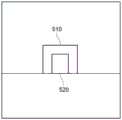
图5A图示了根据一些实施例的二维投影图像;Figure 5A illustrates a two-dimensional projection image in accordance with some embodiments;
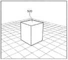
图5B图示了根据一些实施例的三维图像;Figure 5B illustrates a three-dimensional image according to some embodiments;
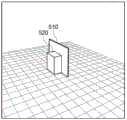
图5C图示了根据一些实施例的合成图像;Figure 5C illustrates a composite image according to some embodiments;
图5D图示了根据一些实施例的旋转合成图像;Figure 5D illustrates a rotated composite image in accordance with some embodiments;
图6图示了根据一些实施例的用于生成合成图像的处理;Figure 6 illustrates a process for generating a composite image in accordance with some embodiments;
图7A图示了根据一些实施例的三维图像;7A illustrates a three-dimensional image according to some embodiments;
图7B图示了根据一些实施例的二维投影图像;7B illustrates a two-dimensional projection image according to some embodiments;
图7C图示了根据一些实施例的经数字重构的放射照片图像;Figure 7C illustrates a digitally reconstructed radiographic image in accordance with some embodiments;
图7D图示了根据一些实施例的示出感兴趣区的合成图像;Figure 7D illustrates a composite image showing a region of interest in accordance with some embodiments;
图8是根据一些实施例的用于生成合成图像的过程的流程图;8 is a flowchart of a process for generating a composite image, according to some embodiments;
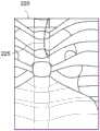
图9描绘了根据一些实施例生成的多个图像切片;9 depicts a plurality of image slices generated in accordance with some embodiments;
图10是根据一些实施例的用于确定、生成和显示多个图像切片的过程的流程图;10 is a flowchart of a process for determining, generating, and displaying a plurality of image slices in accordance with some embodiments;
图11描绘了根据一些实施例生成的多个图像切片和合成图像;Figure 11 depicts a plurality of image slices and a composite image generated in accordance with some embodiments;
图12图示了根据一些实施例的用于显示多个图像切片和合成图像的处理;以及FIG. 12 illustrates a process for displaying multiple image slices and composite images in accordance with some embodiments; and
图13图示了根据一些实施例的用户界面控制装置。Figure 13 illustrates a user interface control device according to some embodiments.
具体实施方式Detailed ways
提供了以下描述,以使任何本领域技术人员能够作出和使用所描述的实施例并阐述所想到的用于实施所描述的实施例的最佳模式。然而,各种修改将对本领域技术人员来说明显。The following description is provided to enable any person skilled in the art to make and use the described embodiments and to set forth the best mode contemplated for carrying out the described embodiments. However, various modifications will be apparent to those skilled in the art.
一些实施例便于将二维图像与三维图像进行组合。根据一些实施例,二维图像(例如,二维血管造影X射线图像)被放置在与二维图像的投影轴正交的三维图像中。投影轴可以是基于二维图像和/或实时获取二维图像的成像系统的位置来确定的。在一些实施例中,二维图像被放置在三维图像的质心处。可以在三维空间中旋转和显示经组合的图像,而二维图像保持在其相对于三维图像的固定位置处。Some embodiments facilitate combining two-dimensional images with three-dimensional images. According to some embodiments, a two-dimensional image (eg, a two-dimensional angiographic X-ray image) is placed in a three-dimensional image orthogonal to the projection axis of the two-dimensional image. The projection axis may be determined based on the two-dimensional image and/or the position of the imaging system that acquires the two-dimensional image in real time. In some embodiments, the two-dimensional image is placed at the centroid of the three-dimensional image. The combined image can be rotated and displayed in three-dimensional space, while the two-dimensional image remains in its fixed position relative to the three-dimensional image.
一些实施例进一步改进被嵌入三维图像内的二维图像的初始对准。简言之,在与二维图像相同的投影角处从三维图像导出经数字重构的放射照片(DRR)。二维图像被配准到DRR,且然后基于配准和质心深度而嵌入三维图像中。Some embodiments further improve the initial alignment of the two-dimensional image embedded within the three-dimensional image. Briefly, a digitally reconstructed radiograph (DRR) is derived from a three-dimensional image at the same projection angle as the two-dimensional image. The two-dimensional image is registered to the DRR and then embedded in the three-dimensional image based on the registration and centroid depth.
根据一些实施例,二维图像被嵌入三维图像中的深度基于感兴趣区的位置。在这点上,确定与投影轴正交且包括该感兴趣区的MPR,并且在MPR的深度处嵌入二维图像。可以进一步将二维图像与MPR配准,以改进其与三维图像的旋转和平移配准。According to some embodiments, the depth at which the two-dimensional image is embedded in the three-dimensional image is based on the location of the region of interest. At this point, an MPR orthogonal to the projection axis and including the region of interest is determined, and a two-dimensional image is embedded at the depth of the MPR. The 2D image can be further registered with the MPR to improve its rotational and translational registration with the 3D image.
一些实施例的潜在优势包括实时地对相关解剖环境信息的增加的访问、在治疗期间获取附加三维图像的减少的需要和所导致的剂量减少、以及患者移动的经改进的检测。Potential advantages of some embodiments include increased access to relevant anatomical environment information in real time, reduced need to acquire additional three-dimensional images during treatment and resulting dose reduction, and improved detection of patient movement.
根据一些实施例,显示若干二维切片段(例如MPR、最大强度分布图、最小强度分布图),其中每一个段的取向与其他取向正交。获取实况二维图像,并且作为响应,改变所显示的二维切片段的取向以反映实况二维图像的投影角。其他所显示的二维切片段的取向也可以被改变为与实况二维图像的投影角正交。According to some embodiments, several two-dimensional slice segments (eg, MPR, maximum intensity profile, minimum intensity profile) are displayed, wherein the orientation of each segment is orthogonal to the other orientations. A live two-dimensional image is acquired, and in response, the orientation of the displayed two-dimensional slice is changed to reflect the projection angle of the live two-dimensional image. The orientation of other displayed 2D slices can also be changed to be orthogonal to the projection angle of the live 2D image.
还可以与从其生成了切片段的三维图像组合地显示实况二维图像,如上所描述。在这种实施例中,可以在实况图像与具有相同角度测量的切片段之间提供切换。此外,可以提供控制装置以改变经组合的三维、实况和切片图像中的每一个图像的相对不透明度。The live two-dimensional image may also be displayed in combination with the three-dimensional image from which the slice was generated, as described above. In such an embodiment, switching between live images and slices with the same angle measurement may be provided. Furthermore, controls may be provided to vary the relative opacity of each of the combined three-dimensional, live and slice images.
因此,一些实施例可以帮助对实况图像与三维图像之间的对应关系进行可视化,特别是在实况图像的投影角发生波动的情况下。Therefore, some embodiments may assist in visualizing the correspondence between the live image and the three-dimensional image, especially if the projection angle of the live image fluctuates.
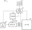
图1是根据一些实施例的系统100的功能框图。可以使用一个或多个计算系统来实现系统100的每一个部件,并且多于一个部件可以由单个计算系统实现。上述计算系统中的任一个可以远离任何其他计算系统而定位。1 is a functional block diagram of a
一般地,成像系统110获取表示患者120的容积的图像数据。该图像数据可以是使用任何成像模态以及以已知或变为已知的任何格式获取的。示例包括但不限于单光子发射计算机断层摄影术(SPECT)、正电子发射断层摄影术(PET)、超声、光声成像、磁性粒子成像、光学相干断层摄影术、光学相机、红外相机、三维相机/深度相机、内窥镜检查术和数字全息显微术。Generally,
使用适于所获取的图像数据的格式的处理算法来对图像数据进行处理,以生成二维图像130。图像130可以包括与投影角相关联的患者120的投影图像(该投影角是在该投影图像中描绘的视图的相对于患者的角度)。图像130可以包括指定用于获取图像数据的获取参数的数据(例如,DICOM数据)。参数可以包括管电流、源到检测器的距离、投影角和其他参数。The image data is processed to generate a two-
储存设备140存储先前获取的图像。该图像可以包括用于计划患者120的治疗或进一步评估的患者120的三维图像。该三维图像可以是基于使用上面提及的成像模态中的任一个而获取的图像数据以及使用任何合适图像重构算法来生成的。将假定三维图像150描绘了患者120的内部容积。The
在一个示例中,患者120的三维图像150是先前获取的且被分段以识别其中的解剖特征。图像150可以在感兴趣特征是软组织的情况下包括磁共振图像以及在特征包括骨头的情况下包括计算机断层摄影术图像。In one example, the three-
患者120被设置在相对于成像系统110的成像位置中,在该示例中,成像系统110包括血管造影术系统。导管被插入到患者120中,并且成像系统110生成包含该导管的患者120的容积的投影图像130。
图像处理器160接收图像130和三维图像150并将这些图像进行组合。例如,图像处理器160确定与图像130相关联的投影角。该投影角可以是通过针对成像系统110的当前位置对其进行查询或通过其他手段、根据图像130的DICOM数据确定的。
图像处理器160然后通过以与投影轴正交的取向将图像130插入到图像150中来生成合成图像170。这种插入要求将三维图像150的参照系配准到图像130/系统110的参照系,如本领域中已知的那样。可以通过确定三维图像130的质心来确定将图像130与三维图像150一起放置的深度。更具体地,可以以与投影轴正交且包括图像150的质心的平面取向将图像130插入到图像150中。
图2A图示了根据一些实施例的患者容积的三维图像210。图像210可以是使用任何容积成像模态来获取的。二维图像220可以包括患者容积的血管造影X射线图像。图像220描绘了患者容积内的导管225。相应地,图像220可以是在医学过程的执行期间获取的。FIG. 2A illustrates a three-
图2C包括根据一些实施例的合成图像230。如上所描述,合成图像230包括在与图像220的投影轴正交的图像210的平面中插入的图像220。此外,在其处插入图像220的平面与图像210的质心相交。如图2C中所示,已经使图像210的处于图像220“前面”的部分部分地透明。这种透明性允许查看图像220的感兴趣的元件(例如,导管225),但会以其他方式被图像210的部分弄模糊。在一些实施例中,裁剪图像210的处于图像220“前面”的部分,以在其中插入图像220的平面的位置处示出切割平面。Figure 2C includes a
图3图示了根据一些实施例的系统1。系统1包括X射线成像系统10、控制和处理系统20、以及操作者终端30。一般地以及根据一些实施例,X射线成像系统10基于患者容积来获取X射线图像数据。控制和处理系统20控制X射线成像系统10并从它接收所获取的图像数据。控制和处理系统20可以如本文描述的那样处理图像,并将经处理的图像提供给终端30从而用于显示。这种处理可以基于由终端30接收到且由终端30提供给控制和处理系统20的用户输入。Figure 3 illustrates
X射线成像系统10包括C臂11,在C臂11上安装了辐射源12和辐射检测器13。C臂11被安装在支撑物14上且被配置成相对于支撑物14顺时针或逆时针平移。该平移使辐射源12和辐射检测器13围绕中央容积旋转,同时维持它们之间的物理关系。实施例不限于基于C臂的成像系统。The X-ray imaging system 10 includes a C-arm 11 on which a radiation source 12 and a radiation detector 13 are mounted. The C-arm 11 is mounted on the support 14 and is configured to translate clockwise or counterclockwise relative to the support 14 . This translation rotates the radiation source 12 and radiation detector 13 around the central volume while maintaining the physical relationship between them. Embodiments are not limited to C-arm based imaging systems.
辐射源12可以包括任何合适的辐射源,该辐射源包括但不限于X射线管。在一些实施例中,辐射源12发射电子、光子或具有范围从50 keV到150 keV变动的能量的其他类型的辐射。Radiation source 12 may comprise any suitable radiation source including, but not limited to, an X-ray tube. In some embodiments, radiation source 12 emits electrons, photons, or other types of radiation with energies ranging from 50 keV to 150 keV.
辐射检测器13可以包括用于基于所接收到的X射线辐射获取图像的任何系统。在一些实施例中,辐射检测器13是使用在二维阵列中部署的固态非晶硅光电二极管和闪烁体层的平板成像设备。该闪烁体层接收光子并生成与所接收到的光子的强度成比例的光。光电二极管的阵列接收该光并记录所接收到的光的强度作为所存储的电荷。The radiation detector 13 may comprise any system for acquiring images based on the received X-ray radiation. In some embodiments, radiation detector 13 is a flat panel imaging device using solid state amorphous silicon photodiodes and scintillator layers deployed in a two-dimensional array. The scintillator layer receives photons and generates light proportional to the intensity of the received photons. An array of photodiodes receives this light and records the intensity of the received light as stored charge.
在其他实施例中,辐射检测器13将所接收到的光子转换成电荷,而无需闪烁体层。光子直接被非晶硒光电导体的阵列吸收。该光电导体将光子直接转换成所存储的电荷。辐射检测器13可以包括基于CCD或管的相机,该相机包括在其内设置闪烁体、镜和相机的不透光外壳。In other embodiments, the radiation detector 13 converts the received photons into electrical charges without the need for a scintillator layer. The photons are directly absorbed by the array of amorphous selenium photoconductors. The photoconductor converts photons directly into stored charge. The radiation detector 13 may comprise a CCD or tube based camera comprising a light-tight housing within which the scintillator, mirror and camera are disposed.
由辐射检测器13形成和存储的电荷表示由从辐射源12发射的X射线产生的辐射场的每一个位置处的辐射强度。辐射场的特定位置处的辐射强度表示沿辐射源12与辐射场的该特定位置之间的发散线定位的组织的衰减特性。由辐射检测器13获取的辐射强度的集合因而可以表示这些组织的二维投影图像。The charge formed and stored by the radiation detector 13 represents the radiation intensity at each location of the radiation field produced by the X-rays emitted from the radiation source 12 . The radiation intensity at a particular location of the radiation field represents the attenuation properties of tissue located along a divergence line between the radiation source 12 and that particular location of the radiation field. The set of radiation intensities acquired by the radiation detector 13 can thus represent a two-dimensional projection image of these tissues.
系统20可以包括任何通用或专用计算系统。相应地,系统20包括:一个或多个处理器21,被配置成执行处理器可执行程序代码,以使系统20如本文描述的那样进行操作;以及储存设备22,用于存储该程序代码。储存设备22可以包括一个或多个固定盘、固态随机存取存储器、和/或在对应接口(例如,USB端口)中安装的可移除介质(例如,拇指驱动器)。
储存设备22存储系统控制程序23的程序代码。一个或多个处理器21可以执行系统控制程序23以移动C臂11、移动台子16、使辐射源12发射辐射、控制检测器13获取图像、以及执行任何其他功能。在这点上,系统20包括用于与系统10的对应单元通信的X射线系统接口24。The storage device 22 stores program codes of the system control program 23 . One or
以DICOM或另一数据格式将从系统10获取的图像数据存储在数据储存设备22中作为所获取的投影图像26。每一个所获取的投影图像可以进一步与其获取的细节相关联,该细节包括但不限于获取时间、成像平面位置和角度、成像位置、辐射源到检测器的距离、所成像的患者解剖结构、患者位置、X射线管电压、图像分辨率和辐射剂量。The image data acquired from the system 10 is stored in the data storage device 22 as the acquired
(一个或多个)处理器21可以进一步执行系统控制程序23以如本领域中已知的那样生成三维图像27和MPR图像28。可以经由系统20的UI接口29将图像26、27和28中的任一个和如本文描述的那样生成的合成图像提供给终端30。UI接口29还可以从终端30接收输入,该输入用于控制如本文描述的合成图像生成。The processor(s) 21 may further execute the system control program 23 to generate three-dimensional images 27 and
终端30可以包括耦合到系统20的显示设备和输入设备。终端30显示从系统20接收到的图像,且可以接收用于控制图像的显示、成像系统10的操作和/或合成图像的生成的用户输入。在一些实施例中,终端30是分离的计算设备,其诸如是但不限于台式计算机、膝上型计算机、平板计算机和智能电话。Terminal 30 may include display devices and input devices coupled to
系统10、系统20和终端30中的每一个可以包括对于其操作而言必要的其他元件以及用于提供除本文描述的那些功能外的功能的附加元件。Each of system 10,
根据所说明的实施例,系统20控制系统10的元件。系统20还处理从系统10接收到的图像。此外,系统20从终端30接收输入并将经处理的图像提供给终端30。实施例不限于执行这些功能中的每一个的单个系统。例如,系统10可以由专用控制系统控制,其中在计算机网络上面或经由物理储存介质(例如,DVD)将所获取的图像提供给分离的图像处理系统。According to the illustrated embodiment,
图4是根据一些实施例的过程400的流程图。可以使用硬件、软件或手动手段的任何合适组合来执行过程400和本文描述的其他过程。体现这些过程的软件可以由任何非瞬变有形介质存储,该非瞬变有形介质包括固定盘、软盘、CD、DVD、闪速驱动器或磁带。下面将关于系统1的元件描述这些过程的示例,但实施例不限于此。FIG. 4 is a flowchart of a
最初,在S410处,获取患者容积的三维图像。该三维图像可以是以已知或变为已知的任何方式生成和获取的。根据一些实施例,该三维图像是在在先图像获取时期期间生成的,且在S410处从在其上存储了图像的数据储存设备获取。Initially, at S410, a three-dimensional image of the patient volume is acquired. The three-dimensional image may be generated and acquired in any manner that is or becomes known. According to some embodiments, the three-dimensional image is generated during a previous image acquisition session, and is acquired at S410 from a data storage device on which the image is stored.
在S420处获取患者容积的二维投影图像。根据一些示例且参照系统1的元件,患者15被定位在台子16上,以将患者15的特定容积放置在辐射源12与辐射检测器13之间。系统20可以帮助调整台子16以如所期望的那样定位患者容积。如本领域中已知的那样,这种定位可以基于感兴趣容积的位置、位于患者15上的定位标记、先前获取的计划图像(例如,在S410处获取的图像)、和/或在最初将患者15定位在台子16上之后获取的视口(portal)图像。A two-dimensional projection image of the patient volume is acquired at S420. According to some examples and with reference to elements of
接着,由高功率发电机对辐射源12供电,以在所期望的投影角处向辐射检测器13发射X射线辐射。X射线辐射发射的参数(例如,定时、X射线管电压、剂量)可以由系统控制程序23控制,如本领域中已知的那样。辐射检测器13接收所发射的辐射并产生数据集(即,投影图像)。该投影图像可以由系统20接收,且以原始形式或在任何合适预处理(例如,降噪滤波器、中值滤波器和低通滤波器)之后存储在投影图像26当中。The radiation source 12 is then powered by a high power generator to emit X-ray radiation to the radiation detector 13 at the desired projection angle. Parameters of X-ray radiation emission (eg, timing, X-ray tube voltage, dose) may be controlled by the system control program 23, as is known in the art. A radiation detector 13 receives the emitted radiation and generates a data set (ie, a projection image). The projected image may be received by
在S430处确定与二维投影图像相关联的投影角。如上所提及,该投影角可以是根据图像130的DICOM数据确定的,或者在例如成像系统10自投影图像的获取起未移动过的情况下通过针对成像系统10的当前位置对成像系统10进行查询而确定。A projection angle associated with the two-dimensional projection image is determined at S430. As mentioned above, the projection angle may be determined from the DICOM data of the
在S440处使用任何合适算法来确定三维图像的质心。所确定的质心可以被表示为三维图像的一个或多个体素。接着,在S450处,确定与投影轴正交且包括所确定的质心的三维图像的平面。根据一些实施例,使用已知技术将二维图像的投影轴(其可以是相对于成像系统10定义的)平移到三维图像的图像空间,并且该平面是相对于经变换的轴和质心体素的位置而确定的。The centroid of the three-dimensional image is determined at S440 using any suitable algorithm. The determined centroids may be represented as one or more voxels of the three-dimensional image. Next, at S450, a plane of the three-dimensional image orthogonal to the projection axis and including the determined centroid is determined. According to some embodiments, the projection axis of the two-dimensional image (which may be defined relative to the imaging system 10 ) is translated into the image space of the three-dimensional image using known techniques, and this plane is relative to the transformed axis and centroid voxels determined by the location.
在S460处在所确定的平面处将二维图像与三维图像进行组合,并且在S470处显示(例如,在终端30上)经组合的图像。如上所提及,在一些实施例中,可以在所确定的平面(即,作为“修剪平面”)处通过二维图像来裁剪三维图像。The two-dimensional image and the three-dimensional image are combined at the determined plane at S460, and the combined image is displayed (eg, on terminal 30) at S470. As mentioned above, in some embodiments, the three-dimensional image may be cropped from the two-dimensional image at the determined plane (ie, as a "cropping plane").
在一些实施例中,在与第一三维图像的投影角不同的投影角处获取(例如,与第一二维图像同时地)第二二维图像。可以以如关于第一二维图像描述的相同方式将第二二维图像与三维图像和第一二维图像组合成合成图像。In some embodiments, the second two-dimensional image is acquired (eg, concurrently with the first two-dimensional image) at a different projection angle than the projection angle of the first three-dimensional image. The second two-dimensional image may be combined with the three-dimensional image and the first two-dimensional image into a composite image in the same manner as described with respect to the first two-dimensional image.
在一些实施例中可以旋转合成图像,同时保持二维图像与三维图像之间的关系。图5A至5D描绘了根据一些实施例的图像。图5A描绘了二维图像510,并且图5B描绘了三维图像520。图5C示出了如上所描述的与图像520组合的图像510。可以如图5D中所示的那样旋转经组合的图像。具体地,图像510保持在图像520的固定平面中,而经组合的图像被旋转,从而提供了它们之间的关系的附加细节。The composite image may be rotated in some embodiments while maintaining the relationship between the two-dimensional and three-dimensional images. 5A-5D depict images according to some embodiments. FIG. 5A depicts a two-
根据一些实施例,流程可以从S470返回到S420以提供实况更新。更具体地,在S470处显示经组合的图像之后,可以在S420处获得另一二维投影图像。该下一个二维图像可以是从与先前获取的二维图像相比相同或不同的投影角获取的。如果该投影角是相同的,则在S460处在先前确定的平面处将该下一个二维图像与三维图像进行组合。如果该投影角是不同的,则在S450处基于不同的投影角和质心来确定下一个平面,并且在S460处在新确定的平面处将该下一个二维图像与三维图像进行组合。According to some embodiments, flow may return from S470 to S420 to provide live updates. More specifically, after displaying the combined image at S470, another two-dimensional projection image may be obtained at S420. The next two-dimensional image may be acquired from the same or a different projection angle than the previously acquired two-dimensional image. If the projection angles are the same, the next two-dimensional image is combined with the three-dimensional image at the previously determined plane at S460. If the projection angles are different, the next plane is determined based on the different projection angles and centroids at S450, and the next two-dimensional image is combined with the three-dimensional image at the newly determined plane at S460.
根据上面关于图1至5描述的示例,如果三维图像由用于获取二维图像的相同系统获取,则典型地,二维图像与三维图像的所确定的平面良好对准。然而,特别地,如果使用不同成像系统以获取图像,则可能的是,二维图像将在与三维图像组合时与三维图像的所确定的平面平移和/或旋转未对准。According to the examples described above with respect to Figures 1 to 5, if the three-dimensional image is acquired by the same system used to acquire the two-dimensional image, the two-dimensional image is typically well aligned with the determined plane of the three-dimensional image. However, in particular if different imaging systems are used to acquire the images, it is possible that the two-dimensional image will be misaligned in translation and/or rotation with the determined plane of the three-dimensional image when combined with the three-dimensional image.
图6图示了用于改进三维图像的所确定的平面与在所确定的平面处插入的二维图像之间的对准的过程600的实施例。6 illustrates an embodiment of a
如上面关于二维图像130描述的那样,二维图像610可以包括与投影角相关联的患者的投影图像。三维图像620可以包括患者的磁共振图像、计算机断层摄影术图像或其他三维图像。如所示的那样,图像610和620由DRR处理器630接收。As described above with respect to two-
DRR处理器630在与二维图像610相同的投影角处从三维图像620导出二维数字重构的放射照片(DRR)图像640。感兴趣区(ROI)部件650自动地和/或结合操作者输入而识别三维图像620内的ROI。配准部件660使用已知配准技术来在ROI处将二维图像610与DRR图像640配准,该已知配准技术包括但不限于每一个图像内的地标检测。The
图像处理器680将经配准的二维图像670和三维图像620进行组合以创建合成图像690。根据一些实施例,在与投影轴正交且包括三维图像620的质心的平面处将经配准的二维图像670嵌入三维图像620中。这些实施例可以提供二维图像670与图像670被嵌入其中的三维图像620之间的合适对准。
在一些实施例中,图像处理器680接收ROI的指示,并在与投影轴正交且包括ROI的平面处嵌入经配准的二维图像670。由于在ROI处将二维图像610与DRR图像640配准,因此这些实施例可以提供二维图像670与图像670被嵌入其中的三维图像620之间的经改进的对准。In some embodiments, the
图7A图示了根据一些实施例的患者容积的三维图像710。例如,ROI 715已经由操作者在图像710中选择。图7B示出了二维X射线图像720,描绘了如关于图2B描述的导管725。FIG. 7A illustrates a three-
图7C包括如本领域中已知的那样基于图像710而生成的DRR图像730。图像730与图像720关联于相同投影角,因此,它们的所描绘的结构是相似的。可以鉴于用于获取图像720的源、检测器和等中心几何结构而生成DRR图像730,从而提高图像720和730之间的相似性并便于它们之间的配准。FIG. 7C includes a
最后,图7D描绘了包括在三维图像710的平面处嵌入的图像720的合成图像740。如上所提及,在与投影轴正交且包括ROI 715的平面处嵌入图像720。还如上所提及,合成图像740可以示出由该平面处的图像720修剪或切掉的三维图像710。Finally, FIG. 7D depicts a
图8是根据一些实施例的过程800的流程图。过程800可以是如关于图6的系统600描述的那样实现的,但实施例不限于此。最初在S810处获取患者容积的三维图像。该三维图像可能已经在在先图像获取时期期间获取和生成。FIG. 8 is a flow diagram of a
在S820处确定三维图像内的感兴趣区。在S820的一些实施例中,在显示设备上显示三维图像,并且操作者操控输入设备以选择所显示的三维图像内的感兴趣区。例如,操作者可以操作鼠标以画出感兴趣容积周围的圆形或球体。为了便于选择感兴趣区,可以在S820之前对三维图像进行分段以识别其中描绘的各种结构和边界,并且可以在所显示的图像中强调结构/边界。A region of interest within the three-dimensional image is determined at S820. In some embodiments of S820, the three-dimensional image is displayed on the display device, and the operator manipulates the input device to select a region of interest within the displayed three-dimensional image. For example, the operator can operate the mouse to draw a circle or sphere around the volume of interest. To facilitate selection of a region of interest, the three-dimensional image may be segmented to identify various structures and boundaries depicted therein prior to S820, and structures/boundaries may be emphasized in the displayed image.
然后在S830处获取患者容积的二维投影图像,并且在S840处确定与该二维投影图像相关联的投影轴。A two-dimensional projection image of the patient volume is then acquired at S830, and a projection axis associated with the two-dimensional projection image is determined at S840.
在S850处,生成三维图像的DRR图像。该DRR图像是基于二维投影图像的投影轴来生成的。如上所提及,该DRR图像可以是鉴于用于在S830处获取二维投影图像的源、检测器和等中心几何结构而生成的。在S860处将二维图像与DRR图像640配准。配准可以包括:识别每一个图像内的相似解剖地标和/或表面标记;以及基于每一个图像内的地标和/或标记的位置来生成变换矩阵。配准可以是刚性的或柔性的,如本领域中已知的那样。根据一些实施例,侧重于实现每一个图像的包括ROI的区之间的准确配准而执行配准。At S850, a DRR image of the three-dimensional image is generated. The DRR image is generated based on the projection axes of the two-dimensional projection image. As mentioned above, the DRR image may be generated in view of the source, detector and isocenter geometry used to acquire the two-dimensional projection image at S830. The two-dimensional image is registered with the
接着,在S870处,确定与投影轴正交的三维图像的平面。可以选择三维图像内的平面的深度以便包括质心。在一些实施例中,所确定的平面与投影轴正交且包括ROI。S870处的确定可以因而包括:确定与投影轴正交且包括ROI的三维图像的MPR;以及确定该MPR内的平面。Next, at S870, a plane of the three-dimensional image orthogonal to the projection axis is determined. The depth of the plane within the three-dimensional image can be chosen to include the centroid. In some embodiments, the determined plane is orthogonal to the projection axis and includes the ROI. The determination at S870 may thus include: determining the MPR of the three-dimensional image orthogonal to the projection axis and including the ROI; and determining the plane within the MPR.
在S880处在所确定的平面处将经配准的二维图像与三维图像进行组合,并且在S890处显示经组合的图像。如上面关于过程400描述的那样,流程可以从S890返回到S830以获取另一二维投影图像。该下一个二维图像可以是从与先前获取的二维图像相比相同或不同的投影角获取的。如果该投影角是相同的,则在S880处在先前确定的平面处将该下一个二维图像与三维图像进行组合。如果该投影角是不同的,则在S870处基于不同的投影角和质心或ROI来确定下一个平面,并且在S880处在新确定的平面处将该下一个二维图像与三维图像进行组合。The registered two-dimensional image is combined with the three-dimensional image at the determined plane at S880, and the combined image is displayed at S890. As described above with respect to process 400, flow may return from S890 to S830 to acquire another two-dimensional projection image. The next two-dimensional image may be acquired from the same or a different projection angle than the previously acquired two-dimensional image. If the projection angles are the same, the next two-dimensional image is combined with the three-dimensional image at the previously determined plane at S880. If the projection angles are different, the next plane is determined at S870 based on the different projection angles and the centroid or ROI, and the next two-dimensional image is combined with the three-dimensional image at the newly determined plane at S880.
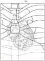
图9图示了包括四个显示区域910至940的显示900。如本领域中已知的那样,区域910、920和930中的每一个显示从在区域940中显示的三维容积取得的切片图像。每一个切片图像表示三维容积的平面,并且这三个所表示的平面中的每一个与其他两个所表示的平面正交。根据典型用途,平面可以是矢状、冠状和轴向解剖平面。FIG. 9 illustrates a
图10是根据一些实施例的用于补充显示(诸如,显示900)的过程1000的流程图。如已经描述的那样,在S1010处获取患者容积的三维图像。在S1020处从该三维图像生成三个图像切片(例如MPR、最大强度分布图、最小强度分布图),如本领域中已知的那样。图像切片中的每一个与其他图像切片正交。10 is a flowchart of a
在S1030处显示每一个图像切片,例如,如图9中所示。实施例不限于显示900的外观和/或配置。Each image slice is displayed at S1030 , eg, as shown in FIG. 9 . Embodiments are not limited to the appearance and/or configuration of
在S1040处获取二维投影图像。如本文所描述,三维图像可以是在前一成像时期期间(例如,在前一天)获取的计划图像,而二维投影图像可以是在S1040处由成像设备在执行过程1000的剩余步骤之前立即获取的。A two-dimensional projection image is acquired at S1040. As described herein, the three-dimensional image may be a planning image acquired during a previous imaging session (eg, on the previous day), while the two-dimensional projection image may be acquired by the imaging device at S1040 immediately prior to performing the remaining steps of the
在S1050处确定所获取的二维投影图像的投影轴,并且在S1060处生成三维图像的第一图像切片。该第一图像切片与该投影轴垂直。切片的深度可以基于三维图像的质心、三维图像的感兴趣区和/或任何其他准则。The projection axis of the acquired two-dimensional projection image is determined at S1050, and a first image slice of the three-dimensional image is generated at S1060. The first image slice is perpendicular to the projection axis. The depth of the slice may be based on the centroid of the three-dimensional image, the region of interest of the three-dimensional image, and/or any other criteria.
在S1070处生成三维图像的第二图像切片。该第二图像切片的平面与第一图像切片的平面正交。接着,在S1080处,生成三维图像的第三图像切片,其中该第三图像切片的平面与第一图像切片的平面和第二图像切片的平面正交。流程返回到S1030以显示新生成的三个正交图像切片并如上面描述的那样继续。A second image slice of the three-dimensional image is generated at S1070. The plane of the second image slice is orthogonal to the plane of the first image slice. Next, at S1080, a third image slice of the three-dimensional image is generated, wherein the plane of the third image slice is orthogonal to the plane of the first image slice and the plane of the second image slice. Flow returns to S1030 to display the three newly generated orthogonal image slices and continues as described above.
因此,如果在S1040处从新投影角获取下一个二维投影图像,则在S1060、S1070和S1080处后续生成的三个切片图像将(如果新投影轴不与最后投影轴正交的话)表示三维图像的三个不同平面。相应地,过程1000提供了基于在S1040处获取的图像的投影轴来更新所显示的切片图像的平面。Therefore, if the next 2D projection image is acquired from the new projection angle at S1040, the three slice images subsequently generated at S1060, S1070 and S1080 will (if the new projection axis is not orthogonal to the last projection axis) represent the 3D image three different planes. Accordingly,
图11图示了其中显示区域1140包括从其生成了显示区域1110、1120和1130的切片图像的三维图像1142的实施例。在区域1140中还示出了在S1040处获取且以本文描述的任何方式或以其他方式与图像1142组合的二维图像1144。根据图11实施例,下一个二维图像的获取不仅使得更新区域1110、1120和1130中所示的切片图像的平面,而且使得将该下一个二维图像与三维图像进行组合并在区域1140中显示新组合的图像。11 illustrates an embodiment in which
图12是根据一些实施例的实现过程1100的系统1200的框图。如上所描述,获取三维图像1210和二维图像1220,并且确定二维图像1220的投影角。MPR生成部件1230基于投影角来生成三个MPR图像(MPR1、MPR2和MPR3)。具体地,部件1230在与对应于投影角的投影轴正交的平面中生成三维图像1210的一个MPR图像切片(例如,MPR1),并在与第一MPR切片的平面正交且与彼此正交的平面中生成三维图像1210的两个其他MPR图像切片(例如,MPR2和MPR3)。显示器126如上所描述的那样显示三个图像切片。12 is a block diagram of a
图12的虚线指示了根据一些实施例的三维图像1210和二维图像1220的可选组合和显示。图像处理器1240可以接收图像1210和1220并如上面关于过程400和800描述的那样将图像进行组合。图像处理器1240还可以接收切片图像MPR1,该切片图像MPR1与二维图像1220被嵌入其中的三维图像1210的平面共面。图像处理器1240可以接收在二维图像1220和三维图像1210的组合和显示与切片图像MPR1和三维图像1210的组合和显示之间进行切换的操作者命令。The dashed lines of Figure 12 indicate optional combinations and displays of three-
系统1200还包括不透明度控制装置1250。不透明度控制装置1250可以指示经组合的图像中图像1210和1220中的每一个的相对不透明度。如果经组合的图像包括切片图像MPR1和三维图像1210,则不透明度控制装置1250可以指示这些图像中的每一个的相对不透明度。图像处理器1240使用所指示的不透明度以通知在显示器1260上显示的合成图像的生成。The
图13图示了根据一些实施例的不透明度控制装置1300。不透明度控制装置1300可以由操作者操控,以便控制由图像处理器1240生成的合成图像中二维图像(即,实况)、图像切片(即,MPR)和三维图像(即,VRT)的相对不透明度。在一些实施例中,操作者使用光标1320以选择图标1310并将图标1310拖拽到所图示的三角形的各种位置。每一个顶点对应于关联图像的最大不透明度,而三角形的中心与所有图像的相等不透明度相关联。通过控制相对不透明度,控制装置还允许操作者在合成图像内的三个图像中的任何一个或两个的显示之间进行切换。FIG. 13 illustrates an
本领域技术人员应当领会,在不脱离权利要求的范围和精神的情况下,可以配置上面描述的实施例的各种适配和修改。因此,应当理解,可以以除如本文具体描述的方式外的方式实践权利要求。Those skilled in the art will appreciate that various adaptations and modifications of the above-described embodiments may be configured without departing from the scope and spirit of the claims. Therefore, it is to be understood that the claims may be practiced otherwise than as specifically described herein.
Claims (39)
Priority Applications (1)
| Application Number | Priority Date | Filing Date | Title |
|---|---|---|---|
| CN202310333316.1ACN116363033A (en) | 2017-11-02 | 2018-10-30 | Synthetic image generation based on live images |
Applications Claiming Priority (7)
| Application Number | Priority Date | Filing Date | Title |
|---|---|---|---|
| US201762580598P | 2017-11-02 | 2017-11-02 | |
| US201762580586P | 2017-11-02 | 2017-11-02 | |
| US201762580589P | 2017-11-02 | 2017-11-02 | |
| US62/580598 | 2017-11-02 | ||
| US62/580586 | 2017-11-02 | ||
| US62/580589 | 2017-11-02 | ||
| PCT/EP2018/079714WO2019086457A1 (en) | 2017-11-02 | 2018-10-30 | Generation of composite images based on live images |
Related Child Applications (1)
| Application Number | Title | Priority Date | Filing Date |
|---|---|---|---|
| CN202310333316.1ADivisionCN116363033A (en) | 2017-11-02 | 2018-10-30 | Synthetic image generation based on live images |
Publications (2)
| Publication Number | Publication Date |
|---|---|
| CN111344747Atrue CN111344747A (en) | 2020-06-26 |
| CN111344747B CN111344747B (en) | 2023-12-05 |
Family
ID=64270831
Family Applications (2)
| Application Number | Title | Priority Date | Filing Date |
|---|---|---|---|
| CN201880070858.1AActiveCN111344747B (en) | 2017-11-02 | 2018-10-30 | Systems and methods for generating synthetic images based on live images |
| CN202310333316.1APendingCN116363033A (en) | 2017-11-02 | 2018-10-30 | Synthetic image generation based on live images |
Family Applications After (1)
| Application Number | Title | Priority Date | Filing Date |
|---|---|---|---|
| CN202310333316.1APendingCN116363033A (en) | 2017-11-02 | 2018-10-30 | Synthetic image generation based on live images |
Country Status (4)
| Country | Link |
|---|---|
| US (1) | US11950947B2 (en) |
| CN (2) | CN111344747B (en) |
| DE (1) | DE112018005199T5 (en) |
| WO (1) | WO2019086457A1 (en) |
Families Citing this family (13)
| Publication number | Priority date | Publication date | Assignee | Title |
|---|---|---|---|---|
| GB2536650A (en) | 2015-03-24 | 2016-09-28 | Augmedics Ltd | Method and system for combining video-based and optic-based augmented reality in a near eye display |
| US11980507B2 (en) | 2018-05-02 | 2024-05-14 | Augmedics Ltd. | Registration of a fiducial marker for an augmented reality system |
| US11766296B2 (en) | 2018-11-26 | 2023-09-26 | Augmedics Ltd. | Tracking system for image-guided surgery |
| US20200310622A1 (en)* | 2019-03-28 | 2020-10-01 | Christie Digital Systems Usa, Inc. | Orthographic projection planes for scene editors |
| US12178666B2 (en) | 2019-07-29 | 2024-12-31 | Augmedics Ltd. | Fiducial marker |
| US11980506B2 (en) | 2019-07-29 | 2024-05-14 | Augmedics Ltd. | Fiducial marker |
| US11382712B2 (en) | 2019-12-22 | 2022-07-12 | Augmedics Ltd. | Mirroring in image guided surgery |
| US11389252B2 (en) | 2020-06-15 | 2022-07-19 | Augmedics Ltd. | Rotating marker for image guided surgery |
| US12239385B2 (en) | 2020-09-09 | 2025-03-04 | Augmedics Ltd. | Universal tool adapter |
| US12150821B2 (en) | 2021-07-29 | 2024-11-26 | Augmedics Ltd. | Rotating marker and adapter for image-guided surgery |
| WO2023021448A1 (en) | 2021-08-18 | 2023-02-23 | Augmedics Ltd. | Augmented-reality surgical system using depth sensing |
| EP4511809A1 (en) | 2022-04-21 | 2025-02-26 | Augmedics Ltd. | Systems and methods for medical image visualization |
| IL319523A (en) | 2022-09-13 | 2025-05-01 | Augmedics Ltd | Augmented reality eyewear for image-guided medical intervention |
Citations (11)
| Publication number | Priority date | Publication date | Assignee | Title |
|---|---|---|---|---|
| US20030181809A1 (en)* | 2002-03-11 | 2003-09-25 | Hall Andrew F. | 3D imaging for catheter interventions by use of 2D/3D image fusion |
| CN1535657A (en)* | 2003-04-03 | 2004-10-13 | Method and apparatus for near-practical three-dimensional imaging | |
| CN101082991A (en)* | 2006-05-31 | 2007-12-05 | 西门子公司 | Method for image reconstruction of an object with the aid of projections, and apparatus for carrying out the method |
| US20070297565A1 (en)* | 2004-10-01 | 2007-12-27 | Wofford Mark G | System and method utilizing adaptive radiation therapy framework |
| US20080037843A1 (en)* | 2006-08-11 | 2008-02-14 | Accuray Incorporated | Image segmentation for DRR generation and image registration |
| US20100111389A1 (en)* | 2007-12-06 | 2010-05-06 | Siemens Medical Solutions Usa, Inc. | System and method for planning and guiding percutaneous procedures |
| KR20100054973A (en)* | 2008-11-17 | 2010-05-26 | 삼성전자주식회사 | Method and apparatus for regenerating three dimensional image from two dimensional image |
| US20110033026A1 (en)* | 2008-02-12 | 2011-02-10 | Sirona Dental Systems Gmbh | Method for Creating a Tomographic Image |
| US20110069063A1 (en)* | 2009-07-29 | 2011-03-24 | Siemens Corporation | Catheter rf ablation using segmentation-based 2d-3d registration |
| US20150332508A1 (en)* | 2014-05-13 | 2015-11-19 | Spaceview Inc. | Method for providing a projection to align 3d objects in 2d environment |
| US20160005168A1 (en)* | 2014-07-02 | 2016-01-07 | Covidien Lp | Fluoroscopic pose estimation |
Family Cites Families (15)
| Publication number | Priority date | Publication date | Assignee | Title |
|---|---|---|---|---|
| DE102005041602A1 (en)* | 2005-09-01 | 2007-04-05 | Siemens Ag | Method for displaying a medical implant in an image and medical imaging system |
| US7991105B2 (en) | 2006-10-17 | 2011-08-02 | Koninklijke Philips Electronics N.V. | Visualization of 3D images in combination with 2D projection images |
| DE102009004898A1 (en)* | 2009-01-16 | 2010-08-19 | Siemens Aktiengesellschaft | Method for displaying two different images of a fusion image and device therefor |
| WO2011091300A2 (en)* | 2010-01-24 | 2011-07-28 | Mistretta Medical, Llc | System and method for implementation of 4d time-energy subtraction computed tomography |
| JP5644219B2 (en) | 2010-07-12 | 2014-12-24 | 東京エレクトロン株式会社 | Substrate processing apparatus, substrate processing method, and storage medium |
| WO2012120405A1 (en)* | 2011-03-04 | 2012-09-13 | Koninklijke Philips Electronics N.V. | 2d/3d image registration |
| US9330490B2 (en)* | 2011-04-29 | 2016-05-03 | University Health Network | Methods and systems for visualization of 3D parametric data during 2D imaging |
| JP6157818B2 (en)* | 2011-10-07 | 2017-07-05 | 東芝メディカルシステムズ株式会社 | X-ray diagnostic equipment |
| WO2014002894A1 (en)* | 2012-06-27 | 2014-01-03 | 株式会社 東芝 | Medical-image-processing device, method for same, and x-ray diagnostic device |
| DE102013208897B4 (en)* | 2013-05-14 | 2016-11-10 | Siemens Healthcare Gmbh | Method and device for displaying a target area of a hollow organ of an examination object |
| WO2015054314A1 (en)* | 2013-10-07 | 2015-04-16 | Mentice Inc. | Medical procedure simulation-based radiation estimation and protection |
| JP6476041B2 (en)* | 2015-03-31 | 2019-02-27 | 株式会社Aze | MEDICAL IMAGE DIAGNOSIS DEVICE, ITS CONTROL METHOD, AND PROGRAM |
| DE102015208929B3 (en) | 2015-05-13 | 2016-06-09 | Friedrich-Alexander-Universität Erlangen-Nürnberg | Method for 2D-3D registration, computing device and computer program |
| FR3037785B1 (en)* | 2015-06-26 | 2017-08-18 | Therenva | METHOD AND SYSTEM FOR GUIDING A ENDOVASCULAR TOOL IN VASCULAR STRUCTURES |
| US11406338B2 (en)* | 2017-07-08 | 2022-08-09 | Vuze Medical Ltd. | Apparatus and methods for use with image-guided skeletal procedures |
- 2018
- 2018-10-30WOPCT/EP2018/079714patent/WO2019086457A1/ennot_activeCeased
- 2018-10-30DEDE112018005199.4Tpatent/DE112018005199T5/enactivePending
- 2018-10-30CNCN201880070858.1Apatent/CN111344747B/enactiveActive
- 2018-10-30USUS16/756,512patent/US11950947B2/enactiveActive
- 2018-10-30CNCN202310333316.1Apatent/CN116363033A/enactivePending
Patent Citations (11)
| Publication number | Priority date | Publication date | Assignee | Title |
|---|---|---|---|---|
| US20030181809A1 (en)* | 2002-03-11 | 2003-09-25 | Hall Andrew F. | 3D imaging for catheter interventions by use of 2D/3D image fusion |
| CN1535657A (en)* | 2003-04-03 | 2004-10-13 | Method and apparatus for near-practical three-dimensional imaging | |
| US20070297565A1 (en)* | 2004-10-01 | 2007-12-27 | Wofford Mark G | System and method utilizing adaptive radiation therapy framework |
| CN101082991A (en)* | 2006-05-31 | 2007-12-05 | 西门子公司 | Method for image reconstruction of an object with the aid of projections, and apparatus for carrying out the method |
| US20080037843A1 (en)* | 2006-08-11 | 2008-02-14 | Accuray Incorporated | Image segmentation for DRR generation and image registration |
| US20100111389A1 (en)* | 2007-12-06 | 2010-05-06 | Siemens Medical Solutions Usa, Inc. | System and method for planning and guiding percutaneous procedures |
| US20110033026A1 (en)* | 2008-02-12 | 2011-02-10 | Sirona Dental Systems Gmbh | Method for Creating a Tomographic Image |
| KR20100054973A (en)* | 2008-11-17 | 2010-05-26 | 삼성전자주식회사 | Method and apparatus for regenerating three dimensional image from two dimensional image |
| US20110069063A1 (en)* | 2009-07-29 | 2011-03-24 | Siemens Corporation | Catheter rf ablation using segmentation-based 2d-3d registration |
| US20150332508A1 (en)* | 2014-05-13 | 2015-11-19 | Spaceview Inc. | Method for providing a projection to align 3d objects in 2d environment |
| US20160005168A1 (en)* | 2014-07-02 | 2016-01-07 | Covidien Lp | Fluoroscopic pose estimation |
Non-Patent Citations (2)
| Title |
|---|
| A.J. COMER 等: "Characterising the behaviour of composite single lap bonded joints using digital image correlation", 《INTERNATIONAL JOURNAL OF ADHESION AND ADHESIVES》, vol. 40, pages 215 - 223* |
| 贾骥 等: "网格分解二维投影边界点的三维模型检索方法", 《计算机学报》, no. 12, pages 2119 - 2129* |
Also Published As
| Publication number | Publication date |
|---|---|
| CN111344747B (en) | 2023-12-05 |
| DE112018005199T5 (en) | 2020-06-18 |
| US20200281554A1 (en) | 2020-09-10 |
| CN116363033A (en) | 2023-06-30 |
| WO2019086457A1 (en) | 2019-05-09 |
| US11950947B2 (en) | 2024-04-09 |
Similar Documents
| Publication | Publication Date | Title |
|---|---|---|
| CN111344747B (en) | Systems and methods for generating synthetic images based on live images | |
| US9589336B2 (en) | Reconstruction of image data by means of contour data | |
| JP5775244B2 (en) | System and method for 3D graphical prescription of medical imaging volume | |
| US20210177371A1 (en) | Low dose digital tomosynthesis system and method using artificial intelligence | |
| US12062177B2 (en) | Systems and methods for x-ray tomosynthesis image reconstruction | |
| CN109475337B (en) | System and method for image reconstruction | |
| CN108403135A (en) | The method and system of the computer tomography scanning of the injectivity optimizing of target organ | |
| WO2010146483A1 (en) | Imaging procedure planning | |
| CN110301883B (en) | Image-based wizard for navigating tubular networks | |
| US8559758B2 (en) | Apparatus for determining a modification of a size of an object | |
| CN108271346B (en) | Imaging controller and imaging system | |
| CN102427767B (en) | The data acquisition and visualization formulation that guide is got involved for low dosage in computer tomography | |
| CN107518911A (en) | Medical diagnostic imaging apparatus and medical image-processing apparatus | |
| US10614598B2 (en) | Systems and methods for generating 2D projection from previously generated 3D dataset | |
| CN108701492B (en) | Medical image navigation system | |
| EP4094228A1 (en) | Low dose digital tomosynthesis system and method using artificial intelligence | |
| Trauernicht | Principles of CT and Hybrid Imaging |
Legal Events
| Date | Code | Title | Description |
|---|---|---|---|
| PB01 | Publication | ||
| PB01 | Publication | ||
| SE01 | Entry into force of request for substantive examination | ||
| SE01 | Entry into force of request for substantive examination | ||
| GR01 | Patent grant | ||
| GR01 | Patent grant | ||
| TR01 | Transfer of patent right | Effective date of registration:20240830 Address after:German Phu F Haim Patentee after:Siemens Medical AG Country or region after:Germany Address before:Erlangen Patentee before:Siemens Healthineers AG Country or region before:Germany | |
| TR01 | Transfer of patent right |