CN111338177A - Reflective geometric holographic display system - Google Patents
Reflective geometric holographic display systemDownload PDFInfo
- Publication number
- CN111338177A CN111338177ACN202010303406.2ACN202010303406ACN111338177ACN 111338177 ACN111338177 ACN 111338177ACN 202010303406 ACN202010303406 ACN 202010303406ACN 111338177 ACN111338177 ACN 111338177A
- Authority
- CN
- China
- Prior art keywords
- projector
- reflective
- screen
- display system
- geometric holographic
- Prior art date
- Legal status (The legal status is an assumption and is not a legal conclusion. Google has not performed a legal analysis and makes no representation as to the accuracy of the status listed.)
- Granted
Links
- 238000003384imaging methodMethods0.000claimsabstractdescription74
- 230000003287optical effectEffects0.000claimsabstractdescription42
- 241000282414Homo sapiensSpecies0.000claimsdescription38
- 230000004907fluxEffects0.000claimsdescription26
- 230000033001locomotionEffects0.000claimsdescription26
- 230000002452interceptive effectEffects0.000claimsdescription17
- 230000003993interactionEffects0.000claimsdescription12
- 230000009471actionEffects0.000claimsdescription9
- 230000000875corresponding effectEffects0.000claimsdescription5
- 230000004044responseEffects0.000claimsdescription3
- 230000009466transformationEffects0.000claimsdescription3
- 238000000844transformationMethods0.000claimsdescription2
- 238000013461designMethods0.000abstractdescription20
- 230000000694effectsEffects0.000abstractdescription18
- 230000002829reductive effectEffects0.000abstractdescription4
- 238000010586diagramMethods0.000description20
- 238000012360testing methodMethods0.000description16
- 238000005516engineering processMethods0.000description10
- 238000000034methodMethods0.000description9
- 230000000007visual effectEffects0.000description7
- 230000000052comparative effectEffects0.000description4
- 230000001276controlling effectEffects0.000description4
- 230000014509gene expressionEffects0.000description3
- 238000004519manufacturing processMethods0.000description3
- 230000032683agingEffects0.000description2
- 208000003464asthenopiaDiseases0.000description2
- 230000008859changeEffects0.000description2
- 238000004891communicationMethods0.000description2
- 238000009826distributionMethods0.000description2
- 238000011156evaluationMethods0.000description2
- 230000004424eye movementEffects0.000description2
- 238000005286illuminationMethods0.000description2
- 238000003754machiningMethods0.000description2
- 230000008569processEffects0.000description2
- 238000012545processingMethods0.000description2
- 210000001747pupilAnatomy0.000description2
- 230000004075alterationEffects0.000description1
- 238000004458analytical methodMethods0.000description1
- 230000001427coherent effectEffects0.000description1
- 238000005520cutting processMethods0.000description1
- 230000007812deficiencyEffects0.000description1
- 229910003460diamondInorganic materials0.000description1
- 239000010432diamondSubstances0.000description1
- 208000002173dizzinessDiseases0.000description1
- 230000004438eyesightEffects0.000description1
- 230000017525heat dissipationEffects0.000description1
- 238000011065in-situ storageMethods0.000description1
- 230000031700light absorptionEffects0.000description1
- 230000000670limiting effectEffects0.000description1
- 238000005259measurementMethods0.000description1
- 230000004379myopiaEffects0.000description1
- 208000001491myopiaDiseases0.000description1
- 230000010287polarizationEffects0.000description1
- 238000003672processing methodMethods0.000description1
- 238000011160researchMethods0.000description1
- 230000002441reversible effectEffects0.000description1
- 238000007789sealingMethods0.000description1
- 230000011664signalingEffects0.000description1
- 230000003068static effectEffects0.000description1
- 238000006467substitution reactionMethods0.000description1
- 239000000725suspensionSubstances0.000description1
- 238000010998test methodMethods0.000description1
Images


Classifications
- G—PHYSICS
- G03—PHOTOGRAPHY; CINEMATOGRAPHY; ANALOGOUS TECHNIQUES USING WAVES OTHER THAN OPTICAL WAVES; ELECTROGRAPHY; HOLOGRAPHY
- G03B—APPARATUS OR ARRANGEMENTS FOR TAKING PHOTOGRAPHS OR FOR PROJECTING OR VIEWING THEM; APPARATUS OR ARRANGEMENTS EMPLOYING ANALOGOUS TECHNIQUES USING WAVES OTHER THAN OPTICAL WAVES; ACCESSORIES THEREFOR
- G03B35/00—Stereoscopic photography
- G03B35/18—Stereoscopic photography by simultaneous viewing
Landscapes
- Physics & Mathematics (AREA)
- General Physics & Mathematics (AREA)
- Holo Graphy (AREA)
Abstract
Translated fromChinese

Description
Translated fromChinese技术领域technical field
本发明涉及3D显示领域,尤其是涉及一种反射式几何全息显示系统。The present invention relates to the field of 3D display, in particular to a reflective geometric holographic display system.
背景技术Background technique
3D显示技术相比于传统2D显示技术可以提供深度信息,从而展示出更多的视觉信息,使得显示图像的还原度更高。因此3D显示技术是目前学术研究非常热门的技术。其中基于全息技术的3D显示方案,原理上可以还原真实物理世界的光场分布,从而完全还原3D场景的全部光学特征。传统的全息显示技术是利用光的波动特性同时记录景物的光强信息和相位信息,从而实现对景物的光强、颜色和景深的记录。但是这种方式需要用到相干光进行拍摄和显示,而且拍摄和显示过程光路设置非常苛刻,环境的轻微扰动都会导致拍摄失败,所以一直都无法真正在生活中得到应用。Compared with traditional 2D display technology, 3D display technology can provide depth information, so as to display more visual information and make the displayed image more restored. Therefore, 3D display technology is a very popular technology in academic research at present. Among them, the 3D display scheme based on holographic technology can in principle restore the light field distribution of the real physical world, thereby completely restoring all the optical characteristics of the 3D scene. The traditional holographic display technology uses the wave characteristics of light to record the light intensity information and phase information of the scene at the same time, so as to realize the record of the light intensity, color and depth of field of the scene. However, this method requires the use of coherent light for shooting and display, and the optical path settings during shooting and display are very harsh, and slight disturbances in the environment will cause shooting failure, so it has never been really applied in life.
目前主流的3D显示解决方案(比如影院的3D电影)都是基于视差图像对(立体图像对)的伪3D显示图,并不能够显示真实的3D图像,显示画面的物理焦深是固定的,无法实现不同焦深景物的显示。虽然,现在已经有很多3D的显示技术被提出,但是还没有一种技术可以真正能够显示大尺度、稳定、高品质3D图像。The current mainstream 3D display solutions (such as 3D movies in theaters) are pseudo 3D display images based on parallax image pairs (stereo image pairs), which cannot display real 3D images, and the physical depth of focus of the displayed images is fixed. The display of objects with different depths of focus cannot be achieved. Although many 3D display technologies have been proposed, none of them can really display large-scale, stable, and high-quality 3D images.
申请号为201910875975.1的专利公开了一种新的全息显示方案,该方案完全利用几何光学原理实现了景深信息的再现。但需要非常精确的人眼追踪手段才能够实现3D显示,显示系统的结构局限性也比较大,很多应用场景下无法为其提供足够的系统布局空间,系统复杂、成本较高。另外,这种显示系统的光学参数设置需要精心设计才能够保证理想的显示效果和显示系统的可靠性,否则显示系统可能因为显示参数的不合适,而无法达到理想的显示效果或者无法保证可靠性。此外,这种透射式成像系统还存在光源利用率低的问题。投影光被折射后分成四束光,其中只有一束光参与成像,三束非成像光束容易对形成的像产生干扰,降低成像质量。The patent with the application number of 201910875975.1 discloses a new holographic display scheme, which fully utilizes the principle of geometrical optics to realize the reproduction of depth-of-field information. However, very accurate human eye tracking methods are required to realize 3D display, and the structure of the display system is relatively limited. In many application scenarios, sufficient system layout space cannot be provided for it, and the system is complex and costly. In addition, the optical parameter setting of this display system needs to be carefully designed to ensure the ideal display effect and the reliability of the display system. Otherwise, the display system may not be able to achieve the ideal display effect or ensure reliability due to inappropriate display parameters. . In addition, this transmissive imaging system also has the problem of low utilization of light source. The projection light is refracted and divided into four beams, of which only one beam participates in imaging, and the three non-imaging beams easily interfere with the formed image and reduce the imaging quality.
而公布号为CN108269511A的一种空中悬浮显示系统公开了一种二维平面空气成像的方案,公开了一种逆反射的直角三角形棱镜阵列,其包括一系列直角三角形棱镜的光反射屏,这种直角三角形棱镜只能实现平行于其横截面光线的逆反射成像功能,光线跟截面不平行时,就无法实现逆反射功能,本身不具备调制这些跟其截面不平行的光线的功能,需要另外借助其他光学模组来对光线进行调制进而实现逆反射成像;同时该申请的显示方案为固定显示,用户只能在特定的外置才可以观看到空间的离屏画面,不能实现动态显示,局限性较大。And an air suspension display system with publication number CN108269511A discloses a two-dimensional plane air imaging scheme, and discloses a retro-reflective right-angled triangular prism array, which includes a series of right-angled triangular prism light reflection screens. The right-angled triangular prism can only realize the retro-reflection imaging function of light parallel to its cross-section. When the light is not parallel to the cross-section, the retro-reflection function cannot be realized. It does not have the function of modulating these non-parallel light rays. Other optical modules are used to modulate the light to achieve retro-reflective imaging; at the same time, the display scheme of the application is a fixed display, and users can only view the off-screen image of the space in a specific external device, and dynamic display cannot be realized. larger.
发明内容SUMMARY OF THE INVENTION
为了解决或者部分解决现有技术的不足,提供一种反射式几何全息显示系统,通过引入具备调制任意角度的光线实现逆反射的反射式几何全息屏,对入射光线进行调制,省去了其他的光学模组,一定程度上节约了成本,缩小了系统的占用空间,同时系统采用两个反射式几何全息屏可以提高了光源利用率,避免了非成像光束对像的干扰,大大提高成像质量,此外,还提供了优化的设计参数配置,达到兼顾显示效果和系统可靠性的目的。In order to solve or partially solve the deficiencies of the prior art, a reflective geometric holographic display system is provided. By introducing a reflective geometric holographic screen capable of modulating light at any angle to realize retroreflection, the incident light is modulated, eliminating the need for other The optical module saves the cost to a certain extent and reduces the occupied space of the system. At the same time, the system adopts two reflective geometric holographic screens, which can improve the utilization rate of the light source, avoid the interference of the non-imaging beam on the image, and greatly improve the imaging quality. In addition, an optimized design parameter configuration is provided to achieve the purpose of taking into account the display effect and system reliability.
为解决上述技术问题,本发明提供反射式几何全息显示系统,包括:In order to solve the above-mentioned technical problems, the present invention provides a reflective geometric holographic display system, including:
至少一个投影器,用于在空间投影出画面信息;at least one projector for projecting picture information in space;
辅助成像屏,用于分光;Auxiliary imaging screen for light splitting;
一个位于辅助成像屏一侧或者是两个分别位于辅助成像屏两侧的反射式几何全息屏,用于对照射到其上的光线进行逆反射;A reflective geometric holographic screen located on one side of the auxiliary imaging screen or two reflective geometric holographic screens respectively located on both sides of the auxiliary imaging screen for retroreflection of the light irradiated thereon;
支持结构,分别与投影器、辅助成像屏和反射式几何全息屏相匹配,为三者提供物理结构支撑;Support structure, respectively matching with projector, auxiliary imaging screen and reflective geometric holographic screen, providing physical structural support for the three;
控制器,与投影器电连接,用于控制投影器来调节投影画面的景深和显示内容;a controller, electrically connected with the projector, for controlling the projector to adjust the depth of field and display content of the projected image;
其中,所述反射式几何全息显示系统的视点数为n,所述投影器最外侧镜片的透光部分直径的均值为D分米,所述投影器投影光源功率的均值为P瓦,满足:Wherein, the number of viewpoints of the reflective geometric holographic display system is n, the average diameter of the light-transmitting portion of the outermost lens of the projector is D decimeters, and the average value of the projected light source power of the projector is P watts, which satisfies:

进一步地,所述投影器的显示光通量的均值为L流明,与所述反射式几何全息显示系统的视点数n之间满足:Further, the average value of the displayed luminous flux of the projector is L lumens, which satisfies the relationship with the viewpoint number n of the reflective geometric holographic display system:
n1.27·L≤24000。n1.27 ·L≤24000.
进一步地,所述反射式几何全息显示系统的视点数n与投影器的显示光通量的均值L流明和投影器最外侧镜片的透光部分直径的均值D分米之间满足:Further, the number of viewpoints n of the reflective geometric holographic display system and the average value L lumens of the displayed luminous flux of the projector and the average value D decimeters of the diameter of the light-transmitting part of the outermost lens of the projector satisfy:

进一步地,所述反射式几何全息屏为柔性全息屏,其内部设有一系列横截面为直角三角形或者矩形和直角三角形组合的五边形的柱状基元棱镜,所述柱状基元棱镜内部、沿长度方向上设有若干相间排列的透明层和反射层,所述柱状基元棱镜横截面包含的直角三角形的直角边所在的斜面上设置有一层反射膜,用于对光线进行镜面反射;Further, the reflective geometric holographic screen is a flexible holographic screen, and a series of columnar primitive prisms with a cross-section of a right triangle or a combination of a rectangle and a right triangle are arranged inside the columnar primitive prism. A number of alternately arranged transparent layers and reflective layers are arranged in the length direction, and a layer of reflective film is provided on the inclined surface where the right-angled sides of the right-angled triangle included in the cross-section of the columnar primitive prism are used for specular reflection of light;
所述柱状基元棱镜横截面为直角三角形或者矩形和直角三角形组合的五边形所包含的直角以及透明层和反射层与柱状基元棱镜的长度方向所成角度的误差范围在±5°以内。The cross section of the columnar primitive prism is a right-angled triangle or a pentagon composed of a rectangle and a right-angled triangle, and the error range of the right angle and the angle formed by the transparent layer and the reflective layer and the length direction of the columnar primitive prism is within ±5°. .
进一步地,所述横截面为矩形和直角三角形组合的五边形的柱状基元棱镜内,所述直角三角形部分的棱镜内部不含反射层。Further, the cross section is a pentagonal columnar primitive prism composed of a combination of a rectangle and a right triangle, and the inside of the prism of the right triangle part does not contain a reflective layer.
进一步地,还包含至少一个设置于辅助成像屏的一侧或者两侧的光路折叠镜组,用于调整光路。Further, it also includes at least one optical path folding mirror group disposed on one side or both sides of the auxiliary imaging screen for adjusting the optical path.
进一步地,所述投影器采用能够投影出二维画面的普通投影设备或者是能够投影出三维画面或者分布在空间不同景深处的二维画面组的全息投影设备。Further, the projector adopts a common projection device capable of projecting a two-dimensional picture or a holographic projection device capable of projecting a three-dimensional picture or a group of two-dimensional pictures distributed in different depths of field in space.
进一步地,所述投影器的投影焦深在距离投影器镜头的最外侧镜片0.1m以及0.1m以外的空间内可调。Further, the projection focal depth of the projector can be adjusted in a space other than 0.1m and 0.1m from the outermost lens of the projector lens.
进一步地,所述支持结构为可以变形或者运动的结构,与控制器电连接,所述控制器能够控制支持结构变形或者运动,从而实现投影器、辅助成像屏和反射式几何全息屏三者之间相对运动和/或整体运动。Further, the support structure is a structure that can be deformed or moved, and is electrically connected to the controller, and the controller can control the deformation or movement of the support structure, thereby realizing the combination of the projector, the auxiliary imaging screen and the reflective geometric holographic screen. relative motion and/or overall motion.
进一步地,还包括与控制器电连接的交互动作捕捉单元,所述交互动作捕捉单元用于识别用户的交互动作并将用户交互动作信息发送给控制器,所述控制器根据接收到的交互动作捕捉单元获取的用户交互动作信息调整显示画面内容。Further, it also includes an interactive motion capture unit electrically connected with the controller, the interactive motion capture unit is used to identify the user's interactive action and send the user's interactive action information to the controller, and the controller according to the received interactive action The user interaction action information acquired by the capturing unit adjusts the content of the display screen.
进一步地,还包括与控制器电连接的人眼跟踪单元,所述人眼跟踪单元用于跟踪人眼的位置并将人眼的定位信息发送给控制器,所述控制器根据接收到的人眼跟踪单元获取的人眼定位信息,来控制支持结构做出相应的动作响应,来调整投影器、辅助成像屏和反射式几何全息屏的相对位置和/或整体空间位置,使用户眼睛始终处于系统的可视空间内。Further, it also includes a human eye tracking unit electrically connected to the controller, the human eye tracking unit is used for tracking the position of the human eye and sending the positioning information of the human eye to the controller, and the controller according to the received human eye tracking unit. The human eye positioning information obtained by the eye tracking unit is used to control the support structure to respond accordingly, to adjust the relative position and/or overall spatial position of the projector, auxiliary imaging screen and reflective geometric holographic screen, so that the user's eyes are always in the within the visible space of the system.
进一步地,所述可视空间是以投影器镜头最外侧镜片中心为原点,以镜片中心外法线为Y轴方向,以过原点垂直于水平面的直线为X轴,以过原点垂直于X轴和Y轴的直线为Z轴的坐标系(X,Y,Z)经过一系列光学转化后光学共轭坐标系(X′,Y′,Z′)下,满足以下关系式的空间:Further, the visible space takes the center of the outermost lens of the projector lens as the origin, the outer normal of the lens center as the Y-axis direction, the line passing through the origin perpendicular to the horizontal plane as the X axis, and the origin perpendicular to the X axis. The straight line with the Y axis is the coordinate system of the Z axis (X, Y, Z) after a series of optical transformations. Under the optical conjugate coordinate system (X', Y', Z'), the space that satisfies the following relationship:

其中K为一个扩展常数,单位为分米,K范围为0<K<0.08;Among them, K is an expansion constant, the unit is decimeter, and the range of K is 0<K<0.08;
m为共轭偏差常数,m范围为0≤m≤5。m is the conjugate deviation constant, and the range of m is 0≤m≤5.
与现有技术相比,本发明的优点在于:Compared with the prior art, the advantages of the present invention are:
1、通过引入具备调制任意角度的光线实现逆反射的反射式几何全息屏,对入射光线进行调制,省去了其他的光学模组,一定程度上节约了成本,缩小了系统的占用空间;1. By introducing a reflective geometric holographic screen that can modulate light at any angle to achieve retroreflection, the incident light is modulated, other optical modules are omitted, the cost is saved to a certain extent, and the occupied space of the system is reduced;
2、本发明的显示系统采用两个反射式几何全息屏,并分别设置于辅助成像屏的两侧,成像过程中没有非成像光束的干扰,从而大大提高成像质量,光源利用率高;2. The display system of the present invention adopts two reflective geometric holographic screens, which are respectively arranged on both sides of the auxiliary imaging screen. There is no interference from non-imaging light beams during the imaging process, thereby greatly improving the imaging quality and high light source utilization;
3、通过将支持支持结构设置为可变形或者运动的结构,从而实现投影器、辅助成像屏和反射式几何全息屏三者之间相对运动和/或整体运动,来实现动态显示;3. By setting the supporting structure as a deformable or moving structure, the relative movement and/or the overall movement between the projector, the auxiliary imaging screen and the reflective geometric holographic screen can be realized to achieve dynamic display;
4、合理的光学参数设置能够有效提高全息显示系统的显示效果和可靠性。4. Reasonable optical parameter settings can effectively improve the display effect and reliability of the holographic display system.
附图说明Description of drawings
为了更清楚地说明本发明实施例或现有技术中的技术方案,下面将对实施例或现有技术描述中所需要使用的附图作简单地介绍,显而易见地,下面描述中的附图仅仅是本发明中记载的一些实施例,对于本领域普通技术人员来讲,在不付出创造性劳动的前提下,还可以根据这些附图获得其他的附图。In order to explain the embodiments of the present invention or the technical solutions in the prior art more clearly, the following briefly introduces the accompanying drawings that need to be used in the description of the embodiments or the prior art. Obviously, the accompanying drawings in the following description are only These are some embodiments described in the present invention. For those of ordinary skill in the art, other drawings can also be obtained based on these drawings without any creative effort.
图1为现有全息显示系统的示意图;1 is a schematic diagram of an existing holographic display system;
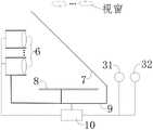
图2为投影器6与一个反射式几何全息屏8位于辅助成像屏7同一侧的本发明系统示意图及光路图;2 is a system schematic diagram and an optical path diagram of the present invention in which the
图3是投影器6与一个反射式几何全息屏8分别位于辅助成像屏7两侧的本发明一种系统示意图及光路图;3 is a system schematic diagram and an optical path diagram of the present invention in which the
图4为两个反射式几何全息屏8分别位于辅助成像屏7两侧的本发明系统示意图及光路图;4 is a schematic diagram and an optical path diagram of the system of the present invention with two reflective geometric
图5是在图2的基础上增加了交互动作捕捉单元31和人眼跟踪单元32的系统示意图;Fig. 5 is a system schematic diagram adding an interactive
图6是在图2的基础上,于投影器6的同一侧增加了光路折叠镜组11的本发明系统示意图;6 is a schematic diagram of the system of the present invention with an optical path folding
图7是在图6的基础上,于辅助成像屏7的另一侧又增加了一个光路折叠镜组11的本发明系统示意图;7 is a schematic diagram of the system of the present invention in which an optical path folding
图8为光线在相互垂直的表面即直角反射壁的反射光路示意图;8 is a schematic diagram of the reflected light path of light rays on mutually perpendicular surfaces, namely right-angle reflecting walls;
图9为隐藏了部分的反射膜84后,横截面为直角三角形的反射式几何全息屏8的结构示意图;FIG. 9 is a schematic structural diagram of a reflective geometric
图10为图8中包括的柱状基元棱镜81对与横截面不平行的光线的逆反射光路图;10 is a retroreflection optical path diagram of the columnar
图11为隐藏了部分的反射膜84后,横截面为矩形和直角三角形组合的五边形的一种反射式几何全息屏8的结构示意图;11 is a schematic structural diagram of a reflective geometric
图12为图10中包括的柱状基元棱镜81对与横截面不平行的光线的逆反射光路图;12 is a retroreflection optical path diagram of the columnar
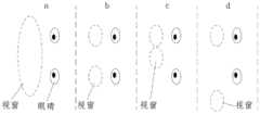
图13为本发明离屏显示的几种视点配置示意图;13 is a schematic diagram of several viewpoint configurations for off-screen display of the present invention;
图14为本发明的一种多视点系统配置示意图;FIG. 14 is a schematic diagram of the configuration of a multi-view system according to the present invention;
图15为距离投影镜头最外侧镜片0.1m以外空间的示意图;Figure 15 is a schematic diagram of the space beyond 0.1m from the outermost lens of the projection lens;
图16为椭球可视空间所在坐标系(X′,Y′,Z′)的示意图;Figure 16 is a schematic diagram of the coordinate system (X', Y', Z') where the ellipsoid visible space is located;
附图标记如下:The reference numbers are as follows:
全息投影仪1,投影屏2,交互响应单元3,处理器4,运动执行机构5,投影器6,辅助成像屏7,反射式几何全息屏8,柱状基元棱镜81,透明层82,反射层83,反射膜84,支持结构9,控制器10,光路折叠镜组11,交互动作捕捉单元31,人眼跟踪单元32。Holographic projector 1,
具体实施方式Detailed ways
为了使本领域技术人员更好地理解本发明的技术方案,下面结合附图对本发明进行详细描述,本部分的描述仅是示范性和解释性,不应对本发明的保护范围有任何的限制作用。In order to make those skilled in the art better understand the technical solutions of the present invention, the present invention will be described in detail below with reference to the accompanying drawings. The description in this part is only exemplary and explanatory, and should not have any limiting effect on the protection scope of the present invention. .
应注意到:相似的标号和字母在下面的附图中表示类似项,因此,一旦某一项在一个附图中被定义,则在随后的附图中不需要对其进行进一步定义和解释。It should be noted that like numerals and letters refer to like items in the following figures, so once an item is defined in one figure, it does not require further definition and explanation in subsequent figures.
需要说明的是,术语“中心”、“上”、“下”、“左”、“右”、“竖直”、“水平”、“内”、“外”等指示的方位或位置关系为基于附图所示的方位或位置关系,或者是该发明产品使用时惯常摆放的方位或位置关系,仅是为了便于描述本发明和简化描述,而不是指示或暗示所指的装置或元件必须具有特定的方位、以特定的方位构造和操作,因此不能理解为对本发明的限制。此外,术语“第一”、“第二”、“第三”等仅用于区分描述,而不能理解为指示或暗示相对重要性。It should be noted that the orientation or positional relationship indicated by the terms "center", "upper", "lower", "left", "right", "vertical", "horizontal", "inner", "outer", etc. Based on the orientation or positional relationship shown in the accompanying drawings, or the orientation or positional relationship that the product of the invention is usually placed in use, it is only for the convenience of describing the present invention and simplifying the description, rather than indicating or implying that the indicated device or element must be It has a specific orientation, is constructed and operates in a specific orientation, and therefore should not be construed as a limitation of the present invention. Furthermore, the terms "first", "second", "third", etc. are only used to differentiate the description and should not be construed as indicating or implying relative importance.
此外,术语“水平”、“竖直”、“悬垂”等术语并不表示要求部件绝对水平或悬垂,而是可以稍微倾斜。如“水平”仅仅是指其方向相对“竖直”而言更加水平,并不是表示该结构一定要完全水平,而是可以稍微倾斜。Furthermore, the terms "horizontal", "vertical", "overhanging" etc. do not imply that a component is required to be absolutely horizontal or overhang, but rather may be slightly inclined. For example, "horizontal" only means that its direction is more horizontal than "vertical", it does not mean that the structure must be completely horizontal, but can be slightly inclined.
在本发明的描述中,还需要说明的是,除非另有明确的规定和限定,术语“设置”、“安装”、“相连”、“连接”应做广义理解,例如,可以是固定连接,也可以是可拆卸连接,或一体地连接;可以是机械连接,也可以是电连接;可以是直接相连,也可以通过中间媒介间接相连,可以是两个元件内部的连通。对于本领域的普通技术人员而言,可以具体情况理解上述术语在本发明中的具体含义。In the description of the present invention, it should also be noted that, unless otherwise expressly specified and limited, the terms "arranged", "installed", "connected" and "connected" should be understood in a broad sense, for example, it may be a fixed connection, It can also be a detachable connection, or an integral connection; it can be a mechanical connection or an electrical connection; it can be a direct connection, or an indirect connection through an intermediate medium, or the internal communication between the two components. For those of ordinary skill in the art, the specific meanings of the above terms in the present invention can be understood in specific situations.
如图2至图7,本发明提供一种反射式几何全息显示系统,包括至少一个投影器6、辅助成像屏7、反射式几何全息屏8、支持结构9和控制器10;2 to 7, the present invention provides a reflective geometric holographic display system, comprising at least one
投影器6是用于在空间投影出画面信息,本发明可以直接采用全息投影仪作为投影器6,实现3D显示;The
也可以采用能够投影二维画面的普通投影设备,实现在空间内的某个焦平面上投影出二维画面,然后通过控制器10来调节二维画面的景深和画面内容。通常影院的3D片源都是立体图像对的形式,通过双目视差来表现出3D效果,但是实际画面焦深是固定在一个位置的,所以会引起视觉疲劳。本发明的系统由于投影及焦深可调,所以可以把画面等效焦深移动到合理的位置,从而避免了3D焦深与实际焦深不同的问题,呈现出更加逼真的3D效果。这种方式相对于全息投影仪作为投影器6来说,可以有效降低成本,具体的,上述普通投影设备可以使用常见的普通投影仪即可;Ordinary projection equipment capable of projecting a two-dimensional image can also be used to project a two-dimensional image on a certain focal plane in space, and then the
还可以使用在空间不同景深处的二维画面组的全息投影设备来实现3D显示,例如,可以进一步对普通投影设备进行光学设计,使之能够在采用单个投影器的基础上实现3D显示,可以参考申请号为202010029144.5的一种全固态全息投影仪,通过在投影器内部通过增加一些光学元件进行光学设计实现三维画面显示的技术方案,这里不做具体限定;It is also possible to use holographic projection equipment with two-dimensional picture groups in different depths of field to achieve 3D display. For example, the optical design of ordinary projection equipment can be further carried out, so that 3D display can be realized on the basis of using a single projector. Reference is made to an all-solid-state holographic projector with application number 202010029144.5, a technical solution for realizing three-dimensional screen display by adding some optical elements inside the projector for optical design, which is not specifically limited here;
辅助成像屏7用于分光,优选半透半反膜,投影器6的投射光线照射到辅助成像屏7之后,部分光线被反射到反射式几何全息屏8上,通过反射式几何全息屏8对光线的调制,使任意照射在反射式几何全息屏8上的光线逆反射后原方向返回,逆反射的光线部分透过辅助成像屏7后在空中形成离屏的投影画面;The
反射式几何全息屏8用于对照射到其上的、与截面不平行的其他角度的入射光线进行逆反射,可以这些光线偏移距离d㎜之后逆反射回去,d为出射光线与反射式几何全息膜入射面的交点到入射光线的距离,d≤2㎜(通常对于类似电影院的巨幕电影,由于用户距离屏幕较远所以像点偏差2mm人眼也不容易分辨,依然可以显示比较清晰的画面,但是偏差过大的话,画质就会受到影响),优选柔性的全息屏,反射式几何全息屏8的数量为一个或者两个:反射式几何全息屏8数量为一个时,将其设置于辅助成像屏7的任意一侧;反射式几何全息屏8数量为两个个时,则分别设置于辅助成像屏7的两侧,当系统包含2个反射式几何全息屏8时,系统的光能利用率和成像质量均较高。The reflective geometric
优选的是,如图9至图12,反射式几何全息屏8的内部设有一系列横截面为直角三角形或者矩形和直角三角形组合的五边形的柱状基元棱镜81,其中上述的直角三角形优选等腰直角三角形;Preferably, as shown in FIG. 9 to FIG. 12 , the interior of the reflective geometric
柱状基元棱镜81内部、沿长度方向上设有若干相间排列的透明层82和反射层83,这种结构可以通过自上而下的二维加工方式获得,加工工艺及其简单,加工精度有非常高,成像质量优异;A number of
柱状基元棱镜81的底面为光线入射面,反射层83、柱状基元棱镜81的端面以及横截面的直角边所在的斜面为反射面,柱状基元棱镜81横截面包含的直角三角形的直角边所在的斜面上设置有一层反射膜84,用于对光线进行镜面反射;The bottom surface of the cylindrical
作为另一种方案,作为反射面的柱状基元棱镜81的端面上也可以设置有一层对光线进行反射的反射膜84,需要说明的,如果在加工过程中,柱状基元棱镜81的端面为反射层83,则无需在该反射层83的端面上镀反射膜84,反射层83本身具有对光线进行镜面反射的功能。As another solution, the end face of the columnar
另外,横截面为矩形和直角三角形组合的五边形的柱状基元棱镜81内,直角三角形部分的棱镜内部可以不含反射层83,这种结构同样可以实现光线的逆反射。In addition, in the cylindrical
上述柱状基元棱镜横截面所涉及的角度误差范围在±5°以内,包括横截面的直角三角形和五边形的直角以及透明层82和反射层83与柱状基元棱镜81的长度方向所成角度,虽然以上原理是基于理想几何形状来实现的,但是实际情况下,加工过程可能无法制造出完全理想的几何形状,角度也会存在一定的误差,顶点也不可能是一个理想的几何点而是一个半径非常小的圆角。当生产制造误差比较小时,反射光的方向跟逆反射理想的情况发生微小偏差,这些偏差人眼无法分辨,由这些误差带来的像差也非常小,因此同样可以实现非常好的成像效果。The angular error range involved in the cross-section of the above-mentioned columnar primitive prism is within ±5°, including the right angle of the cross-section of the right triangle and the pentagon, as well as the length direction formed by the
比如柱状基元棱镜81横截面的包括的直角误差在±5°之内时,用户体验相对比较满意,当超出这个范围后,用户开始觉得成像效果无法接受。同样几何顶点允许是一个比较小的圆角(比如半径小于0.1mm),那么同样可以实现比较好的成像功能。当然误差越小用户评价越高,所以生产时要尽量降低误差。For example, when the included right angle error of the cross section of the columnar
当然误差越小用户评价越高,所以生产时要尽量降低误差。类似的加工误差对于切削方向和粘接方向同样适用。Of course, the smaller the error, the higher the user evaluation, so try to reduce the error during production. Similar machining tolerances apply for the cutting and bonding directions.
具体应用时,客厅应用的角度误差在±2.5°以内时,用户体验相对比较满意;In specific applications, when the angle error of the living room application is within ±2.5°, the user experience is relatively satisfactory;
桌面应用的角度误差在±1°以内时,用户体验相对比较满意;When the angle error of the desktop application is within ±1°, the user experience is relatively satisfactory;
移动终端应用的角度误差在±0.5°以内时,用户体验相对比较满意。When the angle error of the mobile terminal application is within ±0.5°, the user experience is relatively satisfactory.
支持结构9分别与投影器6、辅助成像屏7和反射式几何全息屏8相匹配,为三者提供物理结构支撑,具体可以是将支持结构9可以做成结构固定的支撑架,此时,本发明的显示系统整体是固定不动的,用户需要在一个固定的方位才可以观察到画面;The
控制器10与投影器6电连接,投影器6可以根据控制器10的控制信号来调节投影画面的景深和画面内容;The
逆反射原理说明:如图8,一条光线照射在形成直角的两个反射壁上时,经过两次反射后,出射光线会沿着平行于入射光线的方向传播。当直角反射壁足够小时,出射光线和入射光线之间的距离也会非常小,小到人眼无法分辨,视觉上就像光线原路返回一样。当然,二维平面内直角反射壁只能使平面内的光线进行原路反射,如果能够在空间中形成一个直角三棱锥结构的反射壁,就可以对空间中的光线进行原路反射。Description of the principle of retroreflection: As shown in Figure 8, when a ray irradiates on two reflective walls forming a right angle, after two reflections, the outgoing ray will propagate in a direction parallel to the incident ray. When the right-angle reflective wall is small enough, the distance between the outgoing light and the incoming light will be very small, so small that the human eye cannot distinguish it, and it is visually like the light returning to the original path. Of course, the two-dimensional in-plane right-angle reflective wall can only reflect the light in the plane in the same way. If a reflective wall with a right-angled triangular pyramid structure can be formed in space, the light in the space can be reflected in the same way.
无论是横截面为直角三角形或者矩形和直角三角形组合的五边形都具有多个直角反射壁,包括柱状基元棱镜81的两个斜面形成的直角反射壁以及斜面分别与反射层83或者柱状基元棱镜81的端面形成的直角反射壁,因此这种微结构单元具有对空间的光线进行原路反射的功能,所以如果一个平面上密集布置很多这种微结构,就可以对大面积的入射光进行原路反射。Whether the cross-section is a right-angled triangle or a combination of a rectangle and a right-angled triangle, the pentagon has a plurality of right-angled reflective walls, including the right-angled reflective wall formed by the two inclined surfaces of the columnar
如图10所示,任意与柱状基元棱镜81的横截面不平行的光线从入射面射到反射层83或者是柱状基元棱镜81的端面反射膜84上时,经过一次反射至相邻的一个斜面上,经过该斜面镀的反射膜84的二次反射,将光线反射到另一个斜面上,再经过该斜面上镀的反射膜84的三次反射,即可实现将光线偏移d㎜后平行于入射光的方向反射回去,这些逆反射回去的光线可以进行3D成像;As shown in FIG. 10 , when any light that is not parallel to the cross section of the columnar
同理,如图12所示,任意与柱状基元棱镜81的横截面不平行的光线从入射面射到反射层83或者柱状基元棱镜81的端面的反射膜84上时,也可以经过多次反射后逆反射回去进行3D成像;Similarly, as shown in FIG. 12 , when any light that is not parallel to the cross-section of the columnar
而对于平行于柱状基元棱镜81横截面的入射光,按照图8的光路原理经过两斜面的两次反射即可实现光想逆反射3D成像。As for the incident light parallel to the cross section of the cylindrical
如图5,作为优选方案,本发明所述的全息显示系统还包括与控制器10电连接的交互动作捕捉单元31,交互动作捕捉单元31用于识别用户的交互动作并将用户交互动作信息发送给控制器10,控制器10根据接收到的交互动作捕捉单元31获取的用户交互动作信息调整显示画面内容,实现用户与画面的交互动作,具体可以是采用摄像头结合机器视觉技术来识别用户的手势动作来获取用户的交互信息,从而控制支持结构9运动来调整投影设备和/或辅助成像屏7的空间位置和姿态,控制器10还可以根据接收的交互动作捕捉单元31获取的用户交互动作信息来实时调整显示画面内容,实现用户与画面的交互动作,比如根据平移手势信号,控制画面进行平移,或者根据对应的其他交互动作控制画面的放大、拉近、推远、触碰等操作;As shown in FIG. 5, as a preferred solution, the holographic display system of the present invention further includes an interactive
交互动作捕捉单元31的设置对于类似于穿戴式应用这种用户相对显示系统的空间位置固定不变的应用情景具有积极的意义;The setting of the interactive
另外,对于用户相对显示系统的空间位置实时变动的应用情景,需要设置一个与控制器10电连接的人眼跟踪单元32,人眼跟踪单元32用于跟踪人眼的位置并将人眼的定位信息发送给控制器10,控制器10根据接收到的人眼跟踪单元32获取的人眼定位信息,来控制支持结构9做出相应的动作响应,来调整投影器6和辅助成像屏7的相对位置和/或整体空间位置,使用户眼睛始终处于系统的可视空间内,这样用户即使在运动状态下眼睛也可以始终接收到投影信息,正常观看画面。In addition, for the application scenario in which the spatial position of the user relative to the display system changes in real time, an
实际应用中,人眼跟踪单元32和交互动作捕捉单元31可以集成在同一个设备内完成,比如使用一个机器视觉摄像设备等。In practical applications, the human
为了增加显示系统的灵活性,我们还可以将支持结构9设置为可以运动或者变形的结构,将支持结构9和控制器10电连接,支持结构9根据控制器10的控制信息做出相应响应动作,从而实现投影器6、辅助成像屏7和反射式几何全息屏8三者之间相对运动和/或整体运动,使得系统的可视视窗始终覆盖用户的眼睛,使得用户在不同的方位都可以正常观看画面,需要说明的是支持结构9为一般现有技术,本领域的技术人员可以根据实际应用的空间条件自行设计,比如:使用一些铰链结构和类似于伞轴的结构可以非常容易的设计出可以变形的结构,这里不做具体限定;In order to increase the flexibility of the display system, we can also set the
如图6和图7,为了进一步提升系统的灵活性,还可以在辅助成像屏7的一侧或者两侧设置光路折叠镜组11,光路折叠镜组11中至少包含一面反射镜,这样就可以对成像光路进行调整,使其能够适应各种应用空间场景。对于包含光路折叠镜组11的全息显示系统,还可以通过支持结构9同时控制投影器6、辅助成像屏7、反射式几何全息屏8和光路折叠镜组11四者之间的进行相对或者整体运动从而实时调整,保证用户可以正常观看。As shown in FIG. 6 and FIG. 7 , in order to further improve the flexibility of the system, an optical path folding
以普通投影仪作为投影器6时,控制器10把画面以及画面的平均焦深信息发送给投影器,投影器自己调整投影焦深,投影器就可以把画面投射到特定焦深位置,供人眼观看。When an ordinary projector is used as the
需要说明的是普通投影仪一般有自动对焦功能,开机时投影器会根据内置的距离传感器测量屏幕距离投影器的距离,然后驱动镜头调整到合适的位置,使投影焦深与屏幕重合;在本发明的系统中也可以去除掉其自带的距离传感器,使控制器10直接发送焦深数据到投影器从而实现对投影焦深的控制,具体实现方式为现有成熟硬件通信技术,这里不做赘述。It should be noted that ordinary projectors generally have an auto focus function. When powered on, the projector will measure the distance between the screen and the projector according to the built-in distance sensor, and then drive the lens to adjust to a suitable position so that the projected depth of focus coincides with the screen. The system of the invention can also remove its own distance sensor, so that the
以本发明采用一个投影器6为例进行说明:Taking the present invention using a
如图2,投影器6与一个反射式几何全息屏8位于辅助成像屏7的同一侧,投影器6的投影光线部分经过辅助成像屏7的分光照射到反射式几何全息屏8上,经过反射式几何全息屏8的对光线的逆反射后,原方向反射回并透过辅助成像屏7后,于辅助成像屏7的另一侧形成离屏的显示画面,人眼通过如图所示的视窗即可观看到;As shown in FIG. 2, the
如图3,投影器6与一个反射式几何全息屏8分别位于辅助成像屏7的两侧,投影器6的投影光线部分透过辅助成像屏7后照射到反射式几何全息屏8上,经过反射式几何全息屏8的对光线的逆反射后,原方向反射并经过辅助成像屏7的分光后,于空间内形成离屏的显示画面,人眼通过如图所示的视窗即可观看到;As shown in FIG. 3, the
从图2和图3的光路原理容易发现,当辅助成像屏7为半透半反膜时,光线的能量利用率只有1/4,为了提升光能利用率可以使用一些特殊的光学设计比如偏振+波片的方案,可以大幅度提升光能利用率,具体设计方案为本领域内一般的通识,这里不做赘述。此外,如图4所示,还可以采用两个反射式几何全息屏8的方案,即在辅助成像屏7两侧分别设置两个反射式几何全息屏8,这样可以有效提升系统的光能利用率(提升一倍)和成像质量。It is easy to find from the optical path principle in Figures 2 and 3 that when the
需要说明的,以上只是对本发明进行的举例说明,并不是对本发明的限定,如图14,对于投影器6为多个时,同样适用。It should be noted that the above is only an illustration of the present invention, not a limitation of the present invention. As shown in FIG. 14 , the same applies to a plurality of
本发明所述的反射式几何全息显示系统跟传统显示系统相比有一个非常特殊的地方,它无法像传统2D显示器件一样可以供大量用户同时观看,为了方便表述,这里引入视点的概念:Compared with the traditional display system, the reflective geometric holographic display system of the present invention has a very special place. It cannot be viewed by a large number of users at the same time like a traditional 2D display device. For the convenience of expression, the concept of viewpoint is introduced here:
如果显示系统可以为一只眼睛提供一个观窗,那么这个系统就拥有一个视点。而对于双眼显示系统,可以供两只眼睛同时观看,所以视点数量为2。当显示系统可以供n只眼睛同时观看,视点数量就为n。实际设计时,还需要考虑实用性的情况下合理设置系统的结构。If a display system can provide a viewing window for one eye, then the system has a viewpoint. As for the binocular display system, it can be viewed by both eyes at the same time, so the number of viewpoints is 2. When the display system can be viewed by n eyes at the same time, the number of viewpoints is n. In the actual design, it is also necessary to reasonably set the structure of the system in consideration of practicality.
如图13所示,a情况下,对应于使用一个大口径的投影器,投影器的最外侧镜片相对于辅助成像屏7的光学共轭区(也是镜像对称区,可以称之为视窗)可以覆盖用户的两只眼睛,此时虽然两只眼睛之间的区域原理上也能够观看图像,但是实际条件下却不可能使用到,只能同时供两只眼睛观看,所以这种情形相当于有两个视点;As shown in Figure 13, in case a, corresponding to the use of a large-diameter projector, the outermost lens of the projector can be relative to the optical conjugate area of the auxiliary imaging screen 7 (also a mirror-symmetric area, which can be called a window) Covering the user's two eyes, although the area between the two eyes can also view the image in principle, it is impossible to use under actual conditions, and can only be viewed by two eyes at the same time, so this situation is equivalent to having two viewpoints;
b到d的情况下,对应于使用两个小口径的投影器,两个投影器的投影镜片相对于辅助成像屏7的光学共轭区形成两个分立的子区。当两个子区之间的间距与人眼的间距刚好匹配时就可以供两只眼睛同时观看(b情形),因此有两个视点;In the cases b to d, corresponding to the use of two small-diameter projectors, the projection lenses of the two projectors form two separate sub-regions with respect to the optically conjugated regions of the
当两个子区之间的间距比人眼之间的间距小(c情形)或者比人眼间距大(d情形)时,两只眼睛只有一个能观看到图像,因此只有一个视点。When the distance between the two sub-regions is smaller than the distance between the human eyes (case c) or larger than the distance between the human eyes (case d), only one of the two eyes can see the image, so there is only one viewpoint.
如图14,当投影器的数量更多时,那么系统的视点数就会相应的增多,具体数量根据符合a~d的具体情形而定,显示系统的视点数为n与所采用的投影器的镜头大小以及数量相关。As shown in Figure 14, when the number of projectors is more, the number of viewpoints of the system will increase accordingly. The specific number is determined according to the specific conditions of a to d. The number of viewpoints of the display system is n and the projector used. The size and number of lenses are related.
类似地,对于多用户系统设计时更是需要考虑使用情境下用户之间的空间位置关系,合理设计每个视窗之间的空间分布情况,避免出现系统实际可用视点小于设计视点的情况。一个有效的设计策略是,通过合理设计支持结构9使其具备结构调整功能,比如可以调整两个投影器之间的距离或者空间位置,这样在使用时就可以根据用户瞳距和应用场地灵活调整支持结构9的几何形态来适应实际需求。Similarly, when designing a multi-user system, it is even more necessary to consider the spatial positional relationship between users in the usage situation, and rationally design the spatial distribution of each viewport to avoid the situation that the actual available viewpoint of the system is smaller than the design viewpoint. An effective design strategy is to rationally design the
需要说明的是,当投影系统向下兼容切换到2D投影模式时(如调整投影器的投影焦平面直接在反射式几何全息屏8上投影2D画面,或者用一个普通的投影承接屏替代或者放置在反射式几何全息屏8前表面或者后表面进行2D投影画面的承接显示),图像焦平面与屏幕重合,视点数量会大大增加,但是这些视点具有很大的观看局限性,只能看到屏幕上的画面,显示系统输出的离屏画面都无法观看到,所以不能计入到真正的视点数量里面,实际有效的视点应该是可以观看系统所有模式下的画面的视点。It should be noted that when the projection system is backward compatible and switched to 2D projection mode (such as adjusting the projection focal plane of the projector to directly project a 2D image on the reflective geometric
传统2D显示器件,如电视、投影器、电脑等,视点数量非常多,可以同时被众多用户观看,这是因为其光源发出的光线,发散度较高,无指向性,因此也对亮度要求比较高。但是对于本发明的全息显示系统,视点数都比较少,其显示器件(如全息投影仪或者普通投影仪)发出的光会非常高效的汇集到视窗位置被人眼接收,因此如果光强太强容易造成眩晕,图像不清晰,甚至对人眼造成伤害,同时过高的光通量往往需要光源(如投影器内部的灯泡、LED灯等)在高功率下运行,而光源长期运行在高功率模式下使用寿命就会大幅缩减,所以光通量不能设计的过高。但是,随着视点数量增加,显示系统的总光通量也需要提高,来保证每个视点都能够提供清晰的画面,由于本发明显示系统光路的复杂性,视点与光通量之间并不是简单的线性关系。Traditional 2D display devices, such as TVs, projectors, computers, etc., have a very large number of viewpoints and can be viewed by many users at the same time. This is because the light emitted by its light source has a high degree of divergence and no directivity, so it also has relatively high brightness requirements. high. However, for the holographic display system of the present invention, the number of viewpoints is relatively small, and the light emitted by the display device (such as a holographic projector or a common projector) will be collected at the window position very efficiently and received by the human eye. Therefore, if the light intensity is too strong It is easy to cause dizziness, unclear images, and even damage to human eyes. At the same time, excessive luminous flux often requires the light source (such as bulbs inside the projector, LED lights, etc.) to operate at high power, and the light source runs in high power mode for a long time. The service life will be greatly reduced, so the luminous flux cannot be designed too high. However, as the number of viewpoints increases, the total luminous flux of the display system also needs to be increased to ensure that each viewpoint can provide a clear picture. Due to the complexity of the optical path of the display system of the present invention, there is no simple linear relationship between viewpoints and luminous flux. .
本发明所述的反射式几何全息显示系统的视点数为n,投影器6最外侧镜片的透光部分直径的均值为D分米(dm),投影器6的平均显示光通量为L流明(lm),显示光通量视点积为n1.27·L,综上,结合实际测试效果,显示光通量视点积满足:n1.27·L≤24000时可以够保证比较好的显示效果和系统的可靠性。The number of viewpoints of the reflective geometric holographic display system of the present invention is n, the average diameter of the light-transmitting portion of the outermost lens of the
其中,投影器6的显示光通量L(lm)的测定方法可以参考ANSI流明的测试方法:Wherein, the measuring method of the display luminous flux L (lm) of the
1)将显示系统中的投影器与幕之间距离设置为:2.4米;1) Set the distance between the projector and the screen in the display system to: 2.4 meters;
2)屏幕为60英寸;2) The screen is 60 inches;
3)用照度计测量屏幕“田”字形九个交叉点上的各点照度,并求得9个点的平均照度;3) Measure the illuminance of each point on the nine intersections of the screen "field" shape with an illuminometer, and obtain the average illuminance of the 9 points;
4)平均照度乘以投影画面面积就是ANSI流明,也就是本发明所述的显示光通量。4) The average illuminance multiplied by the projected screen area is ANSI lumens, that is, the display luminous flux described in the present invention.
对于显示不同的画面,L的测试值可能会有较大差异,实际测试中,优选显示全白画面进行测试,即每一个像素都显示为白色的情况;For different pictures displayed, the test value of L may be quite different. In the actual test, it is preferable to display an all-white picture for testing, that is, when each pixel is displayed as white;
当投影器的光照区域无法很好的跟屏幕匹配时,照度测试按照实际光照区域进行取点测试,优选在光照区域内与光照区域的外边界相距约10cm~30cm的光带内较均匀的选取8个点和距离屏幕中心不超过20cm的光照区内1个点,共9个点进行照度测试,然后将9个照度值的平均值与光照区域的实际面积相乘得到显示光通量值。When the illumination area of the projector cannot be well matched with the screen, the illuminance test is carried out according to the actual illumination area. 8 points and 1 point in the lighting area not more than 20cm from the center of the screen, a total of 9 points are tested for illuminance, and then the average value of the 9 illuminance values is multiplied by the actual area of the lighting area to obtain the displayed luminous flux value.
对于只包含一个投影器6的应用案例,可以按照上述方式进行测试显示光通量(单个投影器的显示光通量和平均显示光通量数值一样),当使用到多个投影器时,可以分别测试每个投影单元的光通量然后取平均值作为显示光通量的值。For the application case that includes only one
另外,在实际测试中,不同的设计结构(如密封和散热性的差异)也会对系统的寿命产生比明显的影响,所以实际在测试过程不同的设计结构可能对实测数据带来一定波动,但是整体的趋势不会改变,显示配置参数的最优值不会变化。In addition, in the actual test, different design structures (such as differences in sealing and heat dissipation) will also have a significant impact on the life of the system. Therefore, different design structures in the actual test process may bring certain fluctuations to the measured data. However, the overall trend will not change, and the optimal values of the displayed configuration parameters will not change.
下面以实施例对本发明作进一步说明:The present invention is further described below with embodiment:
以下实施例的系统中投影器6均采用普通投影仪,反射式几何全息屏8均与投影器6位于辅助成像屏7的同一侧;In the systems of the following embodiments, the
实施例1:采用一个镜头直径0.5dm的投影仪作为投影器6,视点数n=1,可以供单户使用单个眼睛进行观看;Embodiment 1: A projector with a lens diameter of 0.5dm is used as the
通常用户眼睛数量为偶数,视点数n设置为偶数:Usually the number of user eyes is an even number, and the number of viewpoints n is set to an even number:
实施例2~24:采用1个镜头直径大于6.5dm的投影仪或者是2个镜头直径小于6.5dm的投影仪作为投影器6,视点数n=2,可以供单户双眼观看;
实施例25:采用4个镜头直径为0.4dm的投影仪作为投影器6,系统视点数n=4,可以供双用户同时观看;Embodiment 25: Four projectors with a lens diameter of 0.4dm are used as the
实施例26:采用6个镜头直径为0.3dm的投影仪作为投影器6,视点数n=6,三口之家可以同时观看;Embodiment 26: Using 6 projectors with a lens diameter of 0.3dm as
实施例27:采用8个镜头直径为0.2dm的投影仪作为投影器6,四口之家同时观看;Embodiment 27: 8 projectors with a lens diameter of 0.2dm are used as
对比例1:采用镜头直径为8dm的投影仪作为投影器6,以供单户双眼观看,具体如下表:Comparative Example 1: A projector with a lens diameter of 8dm is used as the

实施例1~27的数据表明:显示光通量视点积n1.27·L≤24000时,显示效果均较好,用户评分均在80分以上,对比例1中的显示光通量视点积n1.27·L为31351,用户评分低,画面刺眼,实际显示效果欠佳。The data of Examples 1 to 27 show that: when the displayed luminous flux viewpoint product n1.27 ·L≤24000, the display effect is all good, and the user scores are all above 80 points. In Comparative Example 1, the displayed light flux viewpoint product n1.27 ·L is 31351 , the user rating is low, the picture is dazzling, and the actual display effect is not good.
实际使用时,除了需要考虑视点数量n与光通量L之间的设计关系外,还需要投影器孔径大小与光通量之间的匹配。当投影器孔径较大时,显示光的视觉利用率就会偏低,很多光线只能到达人眼之外的区域,所以此时需要适当增加光通量,根据上述实施例1~27的应用,实际应用中可以参考如下表达式进行设计:In actual use, in addition to considering the design relationship between the number of viewpoints n and the luminous flux L, the matching between the aperture size of the projector and the luminous flux is also required. When the aperture of the projector is large, the visual utilization rate of the display light will be low, and a lot of light can only reach the area outside the human eye, so it is necessary to increase the luminous flux appropriately at this time. The application can refer to the following expressions for design:

基于光源功率对于系统显示效果以及可靠性的影响。投影器6内部光源工作在高功率模式下时寿命往往会大幅下降,因此尽可能使其工作在小功率的模式。但是,视点数量较多或者当单个投影器孔径较大时,显示光的视觉利用率就会偏低,很多光线只能到达人眼之外的区域,所以此时需要适当增加光源的功率来提高光通量,投影器6包含的投影器投影光源功率的均值为P瓦(W)测试发现当满足如下关系式的时候,系统可以在一个较优的条件下运行:Based on the influence of light source power on system display effect and reliability. When the light source inside the

投影设备光源功率P的测量可以直接测试其正常工作状态下的光源两端的电压和通过光源的电流然后进行相乘计算得到功率值。The measurement of the light source power P of the projection equipment can directly test the voltage across the light source and the current passing through the light source under its normal working state, and then multiply and calculate to obtain the power value.
在实施例1~27的基础上,再引入光源功率P(W)进行说明,具体见下表:On the basis of Examples 1 to 27, the light source power P (W) is introduced for illustration, and the details are shown in the following table:

数据表明:功率视点积

上述实施方式中采用的普通投影仪还可以用全息投影仪或者其它能够实现三维画面显示的投影设备替代。同时上述涉及到视点数量、光源功率和显示光通量的设计公式对于全息投影仪同样使用。The common projector used in the above embodiments may also be replaced by a holographic projector or other projection devices capable of displaying three-dimensional images. At the same time, the above design formulas involving the number of viewpoints, light source power and display luminous flux are also used for holographic projectors.
另外在实际测试中还发现,实施例1~27的高温高湿环境(85℃、相对湿度85%)加速测试中3000h依然可以正常工作,而对比例1在3000h时光源已经损坏,无法发光,说明不合理的设计参数会大大降低使用寿命,上述的测试俗称双85老化测试,3000h加速老化测试相当于实际工况条件下5年的最低使用寿命标准。In addition, in the actual test, it was also found that the high temperature and high humidity environment (85°C, 85% relative humidity) of Examples 1 to 27 could still work normally for 3000h in the accelerated test, while the light source of Comparative Example 1 was damaged at 3000h and could not emit light. It shows that unreasonable design parameters will greatly reduce the service life. The above test is commonly known as the double 85 aging test. The 3000h accelerated aging test is equivalent to the minimum service life standard of 5 years under actual working conditions.
本发明的显示原理:投影器6可以在空间不同深度处投射出画面,也就是可以为投影画面提供额外的景深信息,但是投影器6投出去的画面都是发散光,无法被人眼直接观看,这也是常规投影系统必须要使用一个承接屏幕的原因。而本发明的反射式几何全息屏8具有使照射到其上的光线原路逆反射的功能。辅助成像屏7是一个具有分光功能的半透半反膜。这样,投影器6发出的光线照射到辅助成像屏7之后,部分光线被反射到反射式几何全息屏8上,由于反射式几何全息屏8的逆反射功能,光线会原路返回(或者近似原路返回),返回的光线再次经过辅助成像屏7,并有部分光线透过辅助成像屏7在空中形成汇聚的离屏投影画面,此时,如果人眼处于投影器6相对于辅助成像屏的镜像位置时(人眼只有在投影器相对于辅助成像屏的镜像位置的一个很小的区域内才可以正常看到完整投影画面),就可以观察到图像。The display principle of the present invention: the
从本发明的显示原理分析可以发现,用户在使用时看到的画面完全跟投影器6投射出去的画面一致。投影器6投射出去的画面距离其最外侧镜片多远,用户看到的画面距离眼睛就多远。生活中,人眼的明视距离一般在25cm,观看最近的物体一般也在10cm之外,所以投影器6选择的时候可以优选投影焦深可以在距离投影镜头最外侧镜片外表面大于0.1m的空间内(如图15)调节的投影器(普通投影仪或者全息投影仪)。From the analysis of the display principle of the present invention, it can be found that the picture the user sees when using is completely consistent with the picture projected by the
用户处于静态时只要调整好系统结构使用户眼睛被视窗覆盖就可以使用户正常观看到画面,但是如果用户处于运动状态就会很容易使眼睛脱离视窗从而无法正常观看画面。因此,针对用户无法完全处于静止状态下的应用场景,增加用户眼睛定位跟踪然后实时调节视窗的空间位置使其始终覆盖用户的眼睛是非常重要的。但是实际场景下,显示系统的元器件参数各不相同,很难找出一套适用于所有系统的跟踪方式。原理上,如果能够非常精准的定位用户眼睛运动轨迹,然后通过调整投影器和透射式几何全息屏之间的相对位置和整体空间位置来驱动视窗精准跟踪用户眼睛运动轨迹是最理想的方案。但是,完全精准的跟踪用户眼睛和精准的控制视窗位置是非常困难的,即使能实现也需要付出比较大的成本代价,实用性不强。When the user is in a static state, as long as the system structure is adjusted so that the user's eyes are covered by the window, the user can view the picture normally. However, if the user is in a motion state, the eyes will be easily separated from the window and the picture cannot be viewed normally. Therefore, for application scenarios where the user cannot be completely stationary, it is very important to increase the tracking of the user's eye position and then adjust the spatial position of the window in real time so that it always covers the user's eyes. However, in actual scenarios, the component parameters of the display system are different, and it is difficult to find a set of tracking methods suitable for all systems. In principle, if the user's eye movement trajectory can be positioned very accurately, and then the relative position and overall spatial position between the projector and the transmissive geometric holographic screen can be adjusted to drive the window to accurately track the user's eye movement trajectory, which is the most ideal solution. However, it is very difficult to completely and accurately track the user's eyes and precisely control the position of the window.
事实上,由于视窗本身有一定大小,人眼只要在视窗之内就可以观看到画面,所以用户运动时并不需要完全精确跟踪用户眼睛的运动轨迹只要能大致跟踪保证用户眼睛在视窗之内即可,甚至稍微偏移出视窗一点,但是瞳孔跟之窗有交集也可以正常观看画面。In fact, because the window itself has a certain size, the human eye can view the picture as long as it is within the window, so the user does not need to completely accurately track the movement trajectory of the user's eyes when moving, as long as the user's eyes can be roughly tracked to ensure that the user's eyes are within the window. Yes, even slightly offset out of the window, but the pupil and the window intersect, you can still watch the picture normally.
以上主要针对用户相对屏幕左右上下移动情况进行的讨论,另外,用户前后移动时,如果不偏离视窗中心太多也完全可以正常观看到画面。综上,对于用户眼睛的跟踪并不需要特别精确,只要保证在一定精度内即可满足使用要求。屏幕上方和下方的光线会有一个相交的菱形区域,原理上只要实时调整支持结构使用户眼睛始终处于上述的菱形可视空间内,即可观察到画面,但是在菱形的靠近角位的地方,比较容易出跟踪丢失的问题,所以在棱形区域的内部进一步限定一个相对较小的椭球可视区域,减小跟踪丢失的概率。The above discussion mainly focuses on the situation where the user moves up and down relative to the screen. In addition, when the user moves back and forth, if the user does not deviate too much from the center of the window, the screen can be viewed normally. To sum up, the tracking of the user's eyes does not need to be particularly accurate, as long as it is guaranteed to be within a certain accuracy, the usage requirements can be met. The light above and below the screen will have an intersecting diamond-shaped area. In principle, as long as the support structure is adjusted in real time so that the user's eyes are always in the above-mentioned diamond-shaped visual space, the screen can be observed, but in the place near the corner of the diamond, The problem of tracking loss is relatively easy to occur, so a relatively small ellipsoid visible area is further defined inside the prismatic area to reduce the probability of tracking loss.
以下对椭球区域进行说明,如图16,椭球可视空间为所述可视空间是以每个投影器6镜头最外侧镜片中心为原点,以镜片中心外法线为Y轴方向,以过原点垂直于水平面的直线为X轴,以过原点垂直于X轴和Y轴的直线为Z轴的坐标系(X,Y,Z)经过光学转化后光学共轭坐标系(X′,Y′,Z′)下,满足以下关系式的空间:The ellipsoid area is described below. As shown in Figure 16, the ellipsoid visible space is the visible space. The center of the outermost lens of each

其中K为一个扩展常数,单位为dm,K范围为0<K<0.08;Among them, K is an expansion constant, the unit is dm, and the range of K is 0<K<0.08;
m为共轭偏差常数,m范围为0≤m≤5。m is the conjugate deviation constant, and the range of m is 0≤m≤5.
上述坐标系(X′,Y′,Z′)是坐标系(X,Y,Z)经过光学系统转换后最终形成的共轭像,以上表达式是一个椭球形围成的空间,其中m的取值影响y轴方向椭球的长度。从示意图16可以看到,可视空间在Y′轴方向有一定延伸,实际测试发现,可视空间在Y′轴方向有一定延伸长度大概在透镜直径D的6倍左右,在这个范围内都可以看到清晰的画面,但是实际考虑到跟踪效果,在Y′轴方向延伸长度小于透镜直径的5倍范围内都可以比较容易实现较好的显示效果。此外,实际测试发现:The above coordinate system (X', Y', Z') is the conjugate image finally formed after the coordinate system (X, Y, Z) is transformed by the optical system. The above expression is a space enclosed by an ellipsoid, where m The value affects the length of the ellipsoid in the y-axis direction. It can be seen from the schematic diagram 16 that the visible space has a certain extension in the Y' axis direction. The actual test found that the visible space has a certain extension length in the Y' axis direction, which is about 6 times the diameter of the lens D. Within this range, all A clear picture can be seen, but actually considering the tracking effect, it is easier to achieve a better display effect when the extension length in the Y'-axis direction is less than 5 times the diameter of the lens. Furthermore, actual testing found:
当m取5时,画面的全部显示区域都可以清晰的看到,只在局部边界区域,画面清晰度稍微差一些但依然可以分辨清楚显示细节;When m is set to 5, the entire display area of the picture can be clearly seen, only in the local boundary area, the picture clarity is slightly worse, but the display details can still be clearly distinguished;
当m取3时,画面的全部显示区域都可以清晰的看到,即使在边界区域,画面也比较清晰,跟踪稳定性也非常好;When m is set to 3, the entire display area of the picture can be clearly seen, even in the boundary area, the picture is relatively clear, and the tracking stability is also very good;
当m取2时,画面的全部显示范围完整,显示细节非常清楚,跟踪稳定性比较好,只是偶尔有跟丢情况,适合桌面办公场景;When m is set to 2, the entire display range of the screen is complete, the display details are very clear, and the tracking stability is relatively good, but there is occasional tracking loss, which is suitable for desktop office scenarios;
当m取1时,画面的全部显示范围完整,显示细节非常清楚,跟踪稳定性稍差,跟丢频率有所增加,适合观影娱乐应用场景;When m is 1, the entire display range of the picture is complete, the display details are very clear, the tracking stability is slightly poor, and the tracking loss frequency increases, which is suitable for movie viewing entertainment application scenarios;
K和D决定了垂直与Y′轴平面内可视空间的截面,原理上投影镜片的直径范围内都可以观看到画面,实际上只要人眼与投影镜片的光学共轭区有相交,即使人员不完全在投影镜片的光学共轭区域之内也可以看到画面,所以引入一个扩展常数K,其数值取决于人眼的直径大小,通常人眼瞳孔的直径最大值是0.08dm,所以这里取0.08dm作为扩展常数。K and D determine the section of the visible space in the plane perpendicular to the Y′ axis. In principle, the picture can be viewed within the diameter of the projection lens. In fact, as long as the human eye intersects the optical conjugate area of the projection lens, even if the human The picture can also be seen not completely within the optical conjugate area of the projection lens, so an expansion constant K is introduced, and its value depends on the diameter of the human eye. Usually, the maximum diameter of the human eye pupil is 0.08dm, so here we take 0.08dm as the expansion constant.
虽然,数学上m不可以取0,但是这里取0有物理上的意义,即Y′都等于0的平面上的点。Although, mathematically, m cannot take 0, but taking 0 here has a physical meaning, that is, a point on the plane where Y' is equal to 0.
本发明在使用多个投影器(普通投影仪或者全息投影仪)时可以选择完全一样的型号,也可以根据实际应用场景需求选用不同的型号。When using multiple projectors (ordinary projectors or holographic projectors) in the present invention, the exact same model can be selected, and different models can also be selected according to actual application scene requirements.
本发明显示系统,由于焦深深度可调,可以避免用户长时间观看固定焦深画面造成的视觉疲劳,从而避免了近视的发生,可以改善视力水平。The display system of the present invention can avoid the visual fatigue caused by the user watching the fixed focal depth picture for a long time due to the adjustable focal depth, thereby avoiding the occurrence of myopia and improving the vision level.
本发明可以用于固定显示,如办公、家厅影音、车载显示等,也可以实现小巧的移动显示和头戴显示等领域。The present invention can be used for fixed display, such as office, home and hall audio-visual, vehicle-mounted display, etc., and can also realize the fields of compact mobile display and head-mounted display.
本发明实施时可以适当增加一些增透膜,吸光膜、滤光片等光学元件来进一步提升系统的效果。During the implementation of the present invention, some optical elements such as antireflection films, light absorption films, filters and the like can be appropriately added to further improve the effect of the system.
以上内容是结合具体的优选实施方式对本发明所作的进一步详细说明,不能认定本发明的具体实施只局限于这些说明。对于本发明所属技术领域的普通技术人员来说,在不脱离本发明构思的前提下,还可以做出若干简单推演或替换,都应当视为属于本发明的保护范围。The above content is a further detailed description of the present invention in combination with specific preferred embodiments, and it cannot be considered that the specific implementation of the present invention is limited to these descriptions. For those of ordinary skill in the technical field of the present invention, without departing from the concept of the present invention, some simple deductions or substitutions can be made, which should be regarded as belonging to the protection scope of the present invention.
Claims (12)
Translated fromChinese


Priority Applications (3)
| Application Number | Priority Date | Filing Date | Title |
|---|---|---|---|
| CN202010303406.2ACN111338177B (en) | 2020-04-17 | 2020-04-17 | Reflective geometric holographic display system |
| PCT/CN2020/110405WO2021052104A1 (en) | 2019-09-17 | 2020-08-21 | Holographic display system |
| US17/753,804US12105305B2 (en) | 2019-09-17 | 2020-08-21 | Holographic display system |
Applications Claiming Priority (1)
| Application Number | Priority Date | Filing Date | Title |
|---|---|---|---|
| CN202010303406.2ACN111338177B (en) | 2020-04-17 | 2020-04-17 | Reflective geometric holographic display system |
Publications (2)
| Publication Number | Publication Date |
|---|---|
| CN111338177Atrue CN111338177A (en) | 2020-06-26 |
| CN111338177B CN111338177B (en) | 2025-03-04 |
Family
ID=71184727
Family Applications (1)
| Application Number | Title | Priority Date | Filing Date |
|---|---|---|---|
| CN202010303406.2AActiveCN111338177B (en) | 2019-09-17 | 2020-04-17 | Reflective geometric holographic display system |
Country Status (1)
| Country | Link |
|---|---|
| CN (1) | CN111338177B (en) |
Cited By (12)
| Publication number | Priority date | Publication date | Assignee | Title |
|---|---|---|---|---|
| CN112085975A (en)* | 2020-09-16 | 2020-12-15 | 联想(北京)有限公司 | Display device and display method |
| WO2021052104A1 (en)* | 2019-09-17 | 2021-03-25 | 荆门市探梦科技有限公司 | Holographic display system |
| CN112946915A (en)* | 2021-02-23 | 2021-06-11 | 荆门市探梦科技有限公司 | Reflective geometric holographic screen with field angle and application thereof |
| CN113253551A (en)* | 2021-06-07 | 2021-08-13 | 荆门市探梦科技有限公司 | Holographic projector and holographic display system |
| CN113296347A (en)* | 2021-04-12 | 2021-08-24 | 北京计算科学研究中心 | Naked eye display device |
| WO2021208941A1 (en)* | 2020-04-17 | 2021-10-21 | 荆门市探梦科技有限公司 | Two-dimensional characteristic-based reflective geometric holographic film and preparation method therefor and use thereof |
| CN114026487A (en)* | 2021-09-23 | 2022-02-08 | 深圳盈天下视觉科技有限公司 | Aerial imaging device, aerial imaging system and aerial imaging method |
| WO2022028448A1 (en)* | 2020-08-06 | 2022-02-10 | 荆门市探梦科技有限公司 | Geometrical holographic display system with optimized display configuration |
| CN114265381A (en)* | 2021-11-11 | 2022-04-01 | 四川华能宝兴河水电有限责任公司 | Remote fault diagnosis system for hydropower station |
| CN114815010A (en)* | 2022-05-15 | 2022-07-29 | 佛山科学技术学院 | A lens array and device for 3D levitation imaging |
| WO2023206351A1 (en)* | 2022-04-29 | 2023-11-02 | 深圳盈天下视觉科技有限公司 | Underwater imaging device |
| WO2025119208A1 (en)* | 2023-12-05 | 2025-06-12 | 上海誉沛光电科技有限公司 | Optical imaging module, array imaging module, floating display apparatus, and multi-layer display device |
Citations (9)
| Publication number | Priority date | Publication date | Assignee | Title |
|---|---|---|---|---|
| US20050219693A1 (en)* | 2004-04-02 | 2005-10-06 | David Hartkop | Scanning aperture three dimensional display device |
| US20100067077A1 (en)* | 2007-01-31 | 2010-03-18 | Seereal Technologies S.A. | Holographic Reconstruction System with Optical Wave Tracking Means |
| CN103488036A (en)* | 2013-09-24 | 2014-01-01 | 苏州苏大维格光电科技股份有限公司 | Holographic solid projection screen and projection method |
| CN104063843A (en)* | 2014-06-18 | 2014-09-24 | 长春理工大学 | Method for generating integrated three-dimensional imaging element images on basis of central projection |
| CN206431409U (en)* | 2017-01-09 | 2017-08-22 | 河北博威集成电路有限公司 | Scene reproduces line holographic projections and shows system |
| CN207198555U (en)* | 2017-09-01 | 2018-04-06 | 深圳市世锟电子有限公司 | Full visual angle 3D demonstration instruments |
| CN108780225A (en)* | 2016-03-08 | 2018-11-09 | 夏普株式会社 | Vehicle-mounted head-up display |
| KR102014973B1 (en)* | 2018-04-04 | 2019-08-27 | 이재환 | Holographic device |
| CN211577657U (en)* | 2020-04-17 | 2020-09-25 | 荆门市探梦科技有限公司 | Reflective geometric holographic display system |
- 2020
- 2020-04-17CNCN202010303406.2Apatent/CN111338177B/enactiveActive
Patent Citations (9)
| Publication number | Priority date | Publication date | Assignee | Title |
|---|---|---|---|---|
| US20050219693A1 (en)* | 2004-04-02 | 2005-10-06 | David Hartkop | Scanning aperture three dimensional display device |
| US20100067077A1 (en)* | 2007-01-31 | 2010-03-18 | Seereal Technologies S.A. | Holographic Reconstruction System with Optical Wave Tracking Means |
| CN103488036A (en)* | 2013-09-24 | 2014-01-01 | 苏州苏大维格光电科技股份有限公司 | Holographic solid projection screen and projection method |
| CN104063843A (en)* | 2014-06-18 | 2014-09-24 | 长春理工大学 | Method for generating integrated three-dimensional imaging element images on basis of central projection |
| CN108780225A (en)* | 2016-03-08 | 2018-11-09 | 夏普株式会社 | Vehicle-mounted head-up display |
| CN206431409U (en)* | 2017-01-09 | 2017-08-22 | 河北博威集成电路有限公司 | Scene reproduces line holographic projections and shows system |
| CN207198555U (en)* | 2017-09-01 | 2018-04-06 | 深圳市世锟电子有限公司 | Full visual angle 3D demonstration instruments |
| KR102014973B1 (en)* | 2018-04-04 | 2019-08-27 | 이재환 | Holographic device |
| CN211577657U (en)* | 2020-04-17 | 2020-09-25 | 荆门市探梦科技有限公司 | Reflective geometric holographic display system |
Cited By (16)
| Publication number | Priority date | Publication date | Assignee | Title |
|---|---|---|---|---|
| WO2021052104A1 (en)* | 2019-09-17 | 2021-03-25 | 荆门市探梦科技有限公司 | Holographic display system |
| US12105305B2 (en) | 2019-09-17 | 2024-10-01 | Jingmen City Dream Exploration Technology Co., Ltd. | Holographic display system |
| WO2021208941A1 (en)* | 2020-04-17 | 2021-10-21 | 荆门市探梦科技有限公司 | Two-dimensional characteristic-based reflective geometric holographic film and preparation method therefor and use thereof |
| WO2022028448A1 (en)* | 2020-08-06 | 2022-02-10 | 荆门市探梦科技有限公司 | Geometrical holographic display system with optimized display configuration |
| CN112085975A (en)* | 2020-09-16 | 2020-12-15 | 联想(北京)有限公司 | Display device and display method |
| CN112946915A (en)* | 2021-02-23 | 2021-06-11 | 荆门市探梦科技有限公司 | Reflective geometric holographic screen with field angle and application thereof |
| CN113296347A (en)* | 2021-04-12 | 2021-08-24 | 北京计算科学研究中心 | Naked eye display device |
| CN113253551A (en)* | 2021-06-07 | 2021-08-13 | 荆门市探梦科技有限公司 | Holographic projector and holographic display system |
| WO2023044670A1 (en)* | 2021-09-23 | 2023-03-30 | 深圳盈天下视觉科技有限公司 | Aerial imaging device, aerial imaging system, and aerial imaging method |
| CN114026487A (en)* | 2021-09-23 | 2022-02-08 | 深圳盈天下视觉科技有限公司 | Aerial imaging device, aerial imaging system and aerial imaging method |
| CN114265381A (en)* | 2021-11-11 | 2022-04-01 | 四川华能宝兴河水电有限责任公司 | Remote fault diagnosis system for hydropower station |
| CN114265381B (en)* | 2021-11-11 | 2024-02-09 | 四川华能宝兴河水电有限责任公司 | Remote fault diagnosis system for hydropower station |
| WO2023206351A1 (en)* | 2022-04-29 | 2023-11-02 | 深圳盈天下视觉科技有限公司 | Underwater imaging device |
| CN114815010B (en)* | 2022-05-15 | 2024-02-09 | 佛山科学技术学院 | Lens array for 3D suspension imaging and device thereof |
| CN114815010A (en)* | 2022-05-15 | 2022-07-29 | 佛山科学技术学院 | A lens array and device for 3D levitation imaging |
| WO2025119208A1 (en)* | 2023-12-05 | 2025-06-12 | 上海誉沛光电科技有限公司 | Optical imaging module, array imaging module, floating display apparatus, and multi-layer display device |
Also Published As
| Publication number | Publication date |
|---|---|
| CN111338177B (en) | 2025-03-04 |
Similar Documents
| Publication | Publication Date | Title |
|---|---|---|
| CN111338177A (en) | Reflective geometric holographic display system | |
| CN113711107B (en) | Augmented reality device and operation method thereof that adjusts the focus area according to the user's line of sight | |
| US9746752B1 (en) | Directional projection display | |
| US20240045377A1 (en) | Relay systems | |
| CN111158162B (en) | Super multi-viewpoint three-dimensional display device and system | |
| US20180284441A1 (en) | Wide field head mounted display | |
| CN103513438B (en) | A multi-view naked-eye stereoscopic display system and display method thereof | |
| WO2021052104A1 (en) | Holographic display system | |
| CN109856808B (en) | floating display device | |
| JP5799535B2 (en) | System for generating aerial 3D image and method for generating aerial 3D image | |
| US11553171B2 (en) | Light field display device and method of processing image of the same | |
| CN111338175B (en) | Transmission type geometric holographic display system | |
| WO2009097746A1 (en) | Three-dimensional displaying method and apparatus based on random constructive interference | |
| JP2014240960A (en) | Aerial image projector | |
| CN211577657U (en) | Reflective geometric holographic display system | |
| CN111338176B (en) | Holographic display system with folded optical path geometry | |
| Brar et al. | Laser-based head-tracked 3D display research | |
| CN110111688B (en) | A display panel, display method and display system | |
| CN110703560A (en) | Direct projection type one-screen multi-eye independent display technology | |
| CN212808904U (en) | Reflective geometric holographic display system with optimized display configuration | |
| CN211528904U (en) | Transmission type geometric holographic display system | |
| CN212541009U (en) | Transmission type geometric holographic display system for optimizing display configuration | |
| WO2022028448A1 (en) | Geometrical holographic display system with optimized display configuration | |
| CN107966892A (en) | A kind of holographic display and its control method | |
| CN110286493B (en) | Stereoscopic projection device based on double gratings |
Legal Events
| Date | Code | Title | Description |
|---|---|---|---|
| PB01 | Publication | ||
| PB01 | Publication | ||
| SE01 | Entry into force of request for substantive examination | ||
| SE01 | Entry into force of request for substantive examination | ||
| CB02 | Change of applicant information | Country or region after:China Address after:448000 building c2-b1, No.39 Jingnan Avenue, Duodao District, Jingmen City, Hubei Province Applicant after:JINGMEN CITY DREAM EXPLORING TECHNOLOGY Co.,Ltd. Address before:448000 shops 101, 201-111211118, 218-128 and 228, 1F and 2F, building c5-5, Renmin Wanfu business city, 201 Peigong Avenue, Duodao District, Jingmen City, Hubei Province Applicant before:JINGMEN CITY DREAM EXPLORING TECHNOLOGY Co.,Ltd. Country or region before:China | |
| CB02 | Change of applicant information | ||
| GR01 | Patent grant | ||
| GR01 | Patent grant |