CN111332277A - Vehicle lateral stability control method based on stable region under limit working condition - Google Patents
Vehicle lateral stability control method based on stable region under limit working conditionDownload PDFInfo
- Publication number
- CN111332277A CN111332277ACN202010152254.0ACN202010152254ACN111332277ACN 111332277 ACN111332277 ACN 111332277ACN 202010152254 ACN202010152254 ACN 202010152254ACN 111332277 ACN111332277 ACN 111332277A
- Authority
- CN
- China
- Prior art keywords
- vehicle
- model
- slip angle
- mass
- center
- Prior art date
- Legal status (The legal status is an assumption and is not a legal conclusion. Google has not performed a legal analysis and makes no representation as to the accuracy of the status listed.)
- Granted
Links
Images


Classifications
- B—PERFORMING OPERATIONS; TRANSPORTING
- B60—VEHICLES IN GENERAL
- B60W—CONJOINT CONTROL OF VEHICLE SUB-UNITS OF DIFFERENT TYPE OR DIFFERENT FUNCTION; CONTROL SYSTEMS SPECIALLY ADAPTED FOR HYBRID VEHICLES; ROAD VEHICLE DRIVE CONTROL SYSTEMS FOR PURPOSES NOT RELATED TO THE CONTROL OF A PARTICULAR SUB-UNIT
- B60W30/00—Purposes of road vehicle drive control systems not related to the control of a particular sub-unit, e.g. of systems using conjoint control of vehicle sub-units
- B60W30/02—Control of vehicle driving stability
- B—PERFORMING OPERATIONS; TRANSPORTING
- B60—VEHICLES IN GENERAL
- B60W—CONJOINT CONTROL OF VEHICLE SUB-UNITS OF DIFFERENT TYPE OR DIFFERENT FUNCTION; CONTROL SYSTEMS SPECIALLY ADAPTED FOR HYBRID VEHICLES; ROAD VEHICLE DRIVE CONTROL SYSTEMS FOR PURPOSES NOT RELATED TO THE CONTROL OF A PARTICULAR SUB-UNIT
- B60W50/00—Details of control systems for road vehicle drive control not related to the control of a particular sub-unit, e.g. process diagnostic or vehicle driver interfaces
- B60W50/0098—Details of control systems ensuring comfort, safety or stability not otherwise provided for
- B—PERFORMING OPERATIONS; TRANSPORTING
- B60—VEHICLES IN GENERAL
- B60W—CONJOINT CONTROL OF VEHICLE SUB-UNITS OF DIFFERENT TYPE OR DIFFERENT FUNCTION; CONTROL SYSTEMS SPECIALLY ADAPTED FOR HYBRID VEHICLES; ROAD VEHICLE DRIVE CONTROL SYSTEMS FOR PURPOSES NOT RELATED TO THE CONTROL OF A PARTICULAR SUB-UNIT
- B60W50/00—Details of control systems for road vehicle drive control not related to the control of a particular sub-unit, e.g. process diagnostic or vehicle driver interfaces
- B60W2050/0001—Details of the control system
- B60W2050/0019—Control system elements or transfer functions
- B60W2050/0028—Mathematical models, e.g. for simulation
- B60W2050/0031—Mathematical model of the vehicle
- B—PERFORMING OPERATIONS; TRANSPORTING
- B60—VEHICLES IN GENERAL
- B60W—CONJOINT CONTROL OF VEHICLE SUB-UNITS OF DIFFERENT TYPE OR DIFFERENT FUNCTION; CONTROL SYSTEMS SPECIALLY ADAPTED FOR HYBRID VEHICLES; ROAD VEHICLE DRIVE CONTROL SYSTEMS FOR PURPOSES NOT RELATED TO THE CONTROL OF A PARTICULAR SUB-UNIT
- B60W50/00—Details of control systems for road vehicle drive control not related to the control of a particular sub-unit, e.g. process diagnostic or vehicle driver interfaces
- B60W2050/0001—Details of the control system
- B60W2050/0019—Control system elements or transfer functions
- B60W2050/0028—Mathematical models, e.g. for simulation
- B60W2050/0037—Mathematical models of vehicle sub-units
- Y—GENERAL TAGGING OF NEW TECHNOLOGICAL DEVELOPMENTS; GENERAL TAGGING OF CROSS-SECTIONAL TECHNOLOGIES SPANNING OVER SEVERAL SECTIONS OF THE IPC; TECHNICAL SUBJECTS COVERED BY FORMER USPC CROSS-REFERENCE ART COLLECTIONS [XRACs] AND DIGESTS
- Y02—TECHNOLOGIES OR APPLICATIONS FOR MITIGATION OR ADAPTATION AGAINST CLIMATE CHANGE
- Y02T—CLIMATE CHANGE MITIGATION TECHNOLOGIES RELATED TO TRANSPORTATION
- Y02T10/00—Road transport of goods or passengers
- Y02T10/10—Internal combustion engine [ICE] based vehicles
- Y02T10/40—Engine management systems
Landscapes
- Engineering & Computer Science (AREA)
- Automation & Control Theory (AREA)
- Transportation (AREA)
- Mechanical Engineering (AREA)
- Human Computer Interaction (AREA)
- Steering Control In Accordance With Driving Conditions (AREA)
- Control Of Driving Devices And Active Controlling Of Vehicle (AREA)
Abstract
Description
Translated fromChinese技术领域technical field
本发明涉及一种极限工况下基于实时稳定边界对车辆进行侧向稳定性控制的方法,更具体地说,本发明涉及实时变化的稳定边界辨识,以此作为约束,设计了一种基于实时稳定边界的MPC控制算法,属于车辆安全控制技术领域。The invention relates to a method for lateral stability control of a vehicle based on a real-time stability boundary under extreme working conditions. The invention discloses an MPC control algorithm of stability boundary, belonging to the technical field of vehicle safety control.
背景技术Background technique
随着科技的高速发展,汽车已经成为人们出行的必备交通工具,而随着汽车的大量普及,提高车辆在行驶过程中的安全性并且减少交通事故成为汽车发展的重大主题。车辆在极限工况下很容易因为道路的问题而加大恶性交通事故发生的可能,保证车辆安全稳定运行尤为重要。现有的稳定区域以及基于稳定边界的控制存在以下问题:With the rapid development of science and technology, automobiles have become an essential means of transportation for people to travel. With the popularization of automobiles, improving the safety of vehicles during driving and reducing traffic accidents have become a major theme of automobile development. Vehicles are prone to increase the possibility of serious traffic accidents due to road problems under extreme working conditions. It is particularly important to ensure the safe and stable operation of vehicles. The existing stable regions and control based on stable boundaries have the following problems:
1.在对稳定区域进行估计时,传统的相平面方法只依靠车辆状态,即不区分车辆和轮胎稳定性,从而忽视了模型中的轮胎力,这就导致了生成的稳定区域会产生不可靠的安全评价。1. When estimating the stable region, the traditional phase plane method only relies on the state of the vehicle, that is, does not distinguish the stability of the vehicle and the tire, thus ignoring the tire force in the model, which leads to the unreliability of the generated stable region. safety evaluation.
2.由于车辆是一个复杂的非线性系统,在轮胎—路面附着极限下,线性的车辆动力学模型很难描述轮胎的非线性,因此需要使用精度更高的非线性动力学模型作为控制器设计的基础。2. Since the vehicle is a complex nonlinear system, under the tire-road adhesion limit, the linear vehicle dynamics model is difficult to describe the nonlinearity of the tire, so it is necessary to use a nonlinear dynamics model with higher accuracy as the controller design. The basics.
3.MPC采用的固定状态约束具有一定的保守性,无法根据车辆实时状态进行更新。3. The fixed state constraints adopted by MPC are conservative and cannot be updated according to the real-time state of the vehicle.
发明内容SUMMARY OF THE INVENTION
为解决现有技术存在的上述问题,本发明提供一种极限工况下基于稳定区域的车辆侧向稳定性控制方法,主要针对车辆在极限工况下,以实时的车辆质心侧偏角和横摆角速度稳定区域边界为约束,以前轮转角和附加横摆力矩作为控制量的稳定性控制方法,使得车辆在处于附着极限时可以稳定安全行驶。In order to solve the above-mentioned problems existing in the prior art, the present invention provides a vehicle lateral stability control method based on the stability area under extreme working conditions, mainly aiming at the vehicle under extreme working conditions, with real-time vehicle center of mass sideslip angle and lateral direction. The boundary of the stable area of yaw rate is the constraint, and the front wheel angle and additional yaw moment are used as the control variables, so that the vehicle can run stably and safely when it is at the adhesion limit.
本发明的目的是采用如下技术方案实现的:The purpose of this invention is to adopt following technical scheme to realize:
一种极限工况下基于稳定区域的车辆侧向稳定性控制方法,包括以下步骤:A vehicle lateral stability control method based on a stable area under extreme working conditions, comprising the following steps:
步骤一、车辆侧向稳定区域的辨识与绘制
1.1)建立描述车辆侧向运动的非线性模型;1.1) Establish a nonlinear model describing the lateral motion of the vehicle;
1.2)将步骤1.1)建立的非线性模型进行局部线性化,并分别得到车辆侧向稳定条件和可控条件;1.2) Perform local linearization of the nonlinear model established in step 1.1), and obtain the vehicle lateral stability conditions and controllable conditions respectively;
1.3)根据车辆侧向稳定条件和可控条件分别得到车辆侧向稳定边界和可控边界,绘制由质心侧偏角和横摆角速度组成的稳定区域;1.3) Obtain the lateral stability boundary and controllable boundary of the vehicle according to the vehicle lateral stability conditions and controllable conditions, respectively, and draw the stable area composed of the center of mass slip angle and yaw rate;
步骤二、基于稳定边界的模型预测控制器的设计
2.1)建立描述车辆侧向运动的二自由度模型;2.1) Establish a two-degree-of-freedom model describing the lateral motion of the vehicle;
2.2)建立车辆参考模型;从所述二自由度模型输出前轮转角给车辆参考模型,得到质心侧偏角参考值和横摆角速度参考值;2.2) Establish a vehicle reference model; output the front wheel rotation angle from the two-degree-of-freedom model to the vehicle reference model, and obtain a center of mass slip angle reference value and a yaw rate reference value;
2.3)设计模型预测控制器,预测模型的状态变量由质心侧偏角和横摆角速度组成,控制量为前轮转角和附加横摆力矩;2.3) Design a model predictive controller, the state variables of the predictive model are composed of the center of mass slip angle and the yaw angular velocity, and the control variables are the front wheel angle and the additional yaw moment;
步骤三、通过模型预测控制器进行车辆侧向稳定性控制:以步骤一得到的车辆侧向稳定区域作为模型预测控制器的状态约束,跟踪车辆参考模型输出的质心侧偏角参考值和横摆角速度参考值,将模型预测控制器得到的输出作用于车辆,对车辆进行稳定性控制。Step 3: Control the lateral stability of the vehicle through the model predictive controller: use the lateral stability region of the vehicle obtained in
与现有的技术相比,本发明的有益效果是:Compared with the prior art, the beneficial effects of the present invention are:
1.本发明对车辆侧向运动进行建模,在进行稳定区域的绘制时并不采用传统的相平面,而是采用Fiala轮胎模型,得到侧向力并求解得到轮胎侧偏刚度。通过将非线性模型进行线性化,可以得到稳定性的判断条件。本发明在得到判断公式后,筛选出符合稳定条件的侧偏角,应用侧偏角公式得到横摆角速度和质心侧偏角,最终得到由横摆角速度和质心侧偏角形成的平面。1. The present invention models the lateral motion of the vehicle, and does not use the traditional phase plane when drawing the stable region, but uses the Fiala tire model to obtain the lateral force and solve to obtain the cornering stiffness of the tire. By linearizing the nonlinear model, the judgment condition of stability can be obtained. After obtaining the judging formula, the invention selects the side slip angle that meets the stability condition, uses the side slip angle formula to obtain the yaw angular velocity and the centroid sideslip angle, and finally obtains the plane formed by the yaw angular velocity and the centroid sideslip angle.
2.本发明克服了传统的相平面方法只依靠车辆状态,即不区分车辆和轮胎稳定性,从而忽视了模型中轮胎力的缺点,将车辆和轮胎稳定性进行综合考虑,使得到的车辆侧向稳定区域更为准确。2. The present invention overcomes the traditional phase plane method that only relies on the vehicle state, that is, does not distinguish the vehicle and tire stability, thereby ignoring the shortcomings of the tire force in the model, and comprehensively considers the vehicle and tire stability, so that the vehicle side It is more accurate to move towards the stable area.
3.本发明将实时的稳定边界作为控制器的约束条件,进而对车辆进行稳定性控制。3. The present invention uses the real-time stability boundary as a constraint condition of the controller, and then performs stability control on the vehicle.
附图说明Description of drawings
图1是本发明方法总体控制框图Fig. 1 is the overall control block diagram of the method of the present invention
图2是本发明方法绘制侧向稳定区域的总体流程框图Fig. 2 is the overall flow chart of the method of the present invention for drawing the lateral stability area
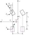
图3是本发明方法绘制侧向稳定区域涉及的非线性车辆侧向动力学模型示意图3 is a schematic diagram of a nonlinear vehicle lateral dynamics model involved in drawing a lateral stability region by the method of the present invention
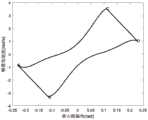
图4是本发明方法涉及不同轮胎路面摩擦系数的侧向力与侧偏角的关系图FIG. 4 is a diagram showing the relationship between the lateral force and the slip angle of the method of the present invention involving different tire road friction coefficients.
图5是本发明方法在Vx=25m/s,μ=0.25,δf=0deg情况下的仿真图,其中虚线是稳定边界,实线是可控边界5 is a simulation diagram of the method of the present invention under the condition of Vx =25m/s, μ=0.25, δf =0deg , wherein the dashed line is the stable boundary and the solid line is the controllable boundary
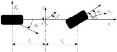
图6是本发明方法在设计控制器时涉及的车辆的二自由度模型Fig. 6 is the two-degree-of-freedom model of the vehicle involved in the method of the present invention when designing the controller
图7是本发明方法在μ=0.25,δf=0deg,Vx变化的情况下的仿真图Fig. 7 is a simulation diagram of the method of the present invention when μ=0.25, δf=0deg , and Vx changes
图8是本发明方法在μ=0.25,Vx=25m/s,δf变化的情况下的仿真图Fig. 8 is a simulation diagram of the method of the present invention when μ=0.25,Vx =25m/s, andδf changes
图9是本发明方法在Vx=25m/s,δf=0deg,μ变化的情况下的仿真图Fig. 9 is a simulation diagram of the method of the present invention when Vx =25m/s, δf =0deg, μ changes
图10是本发明方法在Vx=80km/h,μ=0.8,δf=0deg情况下的仿真图Fig. 10 is a simulation diagram of the method of the present invention under the condition of Vx =80km/h, μ=0.8, δf =0deg
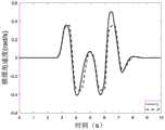
图11是本发明方法跟踪横摆角速度的仿真图Fig. 11 is the simulation diagram of tracking yaw angular velocity by the method of the present invention
图12是本发明方法跟踪质心侧偏角的仿真图Fig. 12 is a simulation diagram of the method of the present invention tracking the side slip angle of the centroid
图13是本发明方法的控制量(前轮转角)的仿真图Fig. 13 is a simulation diagram of the control amount (front wheel rotation angle) of the method of the present invention
图14是本发明方法的控制量(附加横摆力矩)的仿真图Fig. 14 is a simulation diagram of the control amount (additional yaw moment) of the method of the present invention
具体实施方式Detailed ways
为详细说明本发明的技术内容、构造特点、实现目的等下面结合附图对本发明进行全面解释。In order to describe in detail the technical content, structural features, and realization purposes of the present invention, the present invention will be fully explained below with reference to the accompanying drawings.
本发明提出了一种极限工况下基于稳定区域的车辆侧向稳定性控制方法,首先进行极限工况下车辆侧向稳定区域绘制:按照控制器设计要求,建立一个非线性的车辆侧向动力学模型,将这个非线性模型进行线性化,进而得到由车辆的质心侧偏角和横摆角速度组成的侧向稳定区域。进而,以得到的侧向稳定区域作为控制器的约束,以二阶参考模型的输出β*,r*作为控制器的参考值,以前轮转角和附加横摆力矩作为控制量,对车进行实时跟踪控制。其中二阶参考模型以及模型预测控制器都是在Simulink中搭建的。The invention proposes a vehicle lateral stability control method based on the stability area under extreme working conditions. First, the vehicle lateral stability area under extreme working conditions is drawn: according to the controller design requirements, a nonlinear vehicle lateral dynamic force is established. The nonlinear model is linearized to obtain the lateral stability region composed of the vehicle's center of mass slip angle and yaw rate. Furthermore, the obtained lateral stability region is used as the constraint of the controller, the output β* , r* of the second-order reference model is used as the reference value of the controller, and the front wheel angle and the additional yaw moment are used as the control variables, and the real-time control of the vehicle is carried out. tracking control. The second-order reference model and the model predictive controller are built in Simulink.
本发明的目标是,在极限工况下实现车辆的稳定性控制。The object of the present invention is to realize the stability control of the vehicle under extreme operating conditions.
本发明所述的车辆在行驶过程中的侧向稳定性控制是通过软件系统的联合仿真实现的。The lateral stability control of the vehicle in the running process of the present invention is realized through the joint simulation of the software system.
1、软件选择1. Software selection
该侧向稳定区域及其相应的控制器和由控制器控制的被控对象的仿真模型分别通过软件Matlab/Simulink和高保真车辆动力学仿真软件CarSim进行搭建,软件版本分别为MatlabR2016a和CarSim2016.1,求解器选择为ODE1。仿真步长为0.001s。其中CarSim软件是一个商用的高保真车辆动力学仿真平台,它在本发明中的主要作用是提供高保真的车辆动力学模型以及相应的仿真工况,在仿真实验中这一模型代替了真实的车辆作为所设计的稳定边界约束的实施对象;MATLAB/Simulink软件则是用于控制器的仿真模型搭建,即通过Simulink编程来完成该方法中控制器的运算。The lateral stability region and its corresponding controller and the simulation model of the controlled object controlled by the controller are constructed by the software Matlab/Simulink and the high-fidelity vehicle dynamics simulation software CarSim respectively. The software versions are MatlabR2016a and CarSim2016.1 respectively. , the solver selection is ODE1. The simulation step size is 0.001s. The CarSim software is a commercial high-fidelity vehicle dynamics simulation platform. Its main function in the present invention is to provide a high-fidelity vehicle dynamics model and corresponding simulation conditions. In the simulation experiment, this model replaces the real vehicle dynamics model. The vehicle is used as the implementation object of the designed stability boundary constraints; MATLAB/Simulink software is used to build the simulation model of the controller, that is, the operation of the controller in this method is completed through Simulink programming.
2、联合仿真设置2. Co-simulation settings
要实现两者的联合仿真,首先需要在Matlab的路径设置中添加CarSim的路径;其次在CarSim界面中添加输出接口模块;然后将CarSim中的模型信息经过系统编译之后以CarSimS-function的形式保留在Simulink中,最后再进行Simulink中CarSim模块的参数设置。在运行Simulink仿真模型时,CarSim模型也在同时进行计算和求解。仿真过程中两者之间不断进行数据的交换。如果对CarSim中的模型结构或者参数设置进行了修改,则需要重新编译,之后将新的包含最新设定信息的CarSim模块重新发送至Simulink中。To realize the co-simulation of the two, firstly, the path of CarSim needs to be added in the path setting of Matlab; secondly, the output interface module needs to be added in the interface of CarSim; then the model information in CarSim is compiled by the system and retained in the form of CarSimS-function in the form of CarSimS-function. In Simulink, finally set the parameters of the CarSim module in Simulink. When running the Simulink simulation model, the CarSim model is also being calculated and solved simultaneously. During the simulation process, the data exchange between the two is constantly carried out. If you modify the model structure or parameter settings in CarSim, you need to recompile, and then re-send the new CarSim module containing the latest setting information to Simulink.
本发明所述的车辆侧向稳定性控制方法,首先,将非线性车辆动力学模型经过泰勒展开进行局部线性化;其次,通过线性系统的特征值与稳定性的关系推导出稳定边界的判断条件进而画出稳态边界;之后,在高保真车辆动力学仿真软件CarSim中选择合适的车辆模型并获取相应参数;然后将基于本发明绘制的稳定边界作为设计控制器的约束,同时将Simulink中搭建的二阶参考模型的输出作为其参考值,最后在联合仿真实验中选定一组工况对本发明所述稳定性控制方法进行验证。In the vehicle lateral stability control method of the present invention, firstly, the nonlinear vehicle dynamics model is locally linearized through Taylor expansion; secondly, the judgment condition of the stability boundary is deduced through the relationship between the eigenvalues of the linear system and the stability Then draw the steady-state boundary; after that, select the appropriate vehicle model in the high-fidelity vehicle dynamics simulation software CarSim and obtain the corresponding parameters; then use the stable boundary drawn based on the present invention as the constraint of designing the controller, and at the same time build in Simulink The output of the second-order reference model is taken as its reference value, and finally a set of working conditions are selected in the co-simulation experiment to verify the stability control method of the present invention.
本发明的总体控制框图如图1,从驾驶员模型输出前轮转角,将非线性车辆动力学模型线性化后得到稳定区域的判断条件,进而绘制出由质心侧偏角β'和横摆角速度r'形成的稳定边界;从驾驶员模型输出前轮转角给二阶参考模型,得到质心侧偏角的参考值β*和横摆角速度参考值r*;将稳定边界作为控制器的约束,跟踪二阶参考模型得到的参考值,对前轮转角和附加横摆力矩进行控制,再将控制得到的输出作用于车,如此,可以实现在稳定边界的限制下对车辆进行稳定性控制。The overall control block diagram of the present invention is shown in Figure 1. The front wheel rotation angle is output from the driver model, and the non-linear vehicle dynamics model is linearized to obtain the judgment condition of the stable region, and then the center of mass slip angle β' and the yaw angular velocity are drawn. The stabilityboundaryformed by the The reference value obtained from the second-order reference model controls the front wheel angle and additional yaw moment, and then the output obtained from the control acts on the vehicle. In this way, the stability control of the vehicle can be realized under the limit of the stability boundary.
本发明具体包括以下步骤:The present invention specifically includes the following steps:
步骤一、车辆侧向稳定区域的绘制:
1)建立描述车辆侧向运动的非线性车辆侧向动力学模型,该模型如图3。1) Establish a nonlinear vehicle lateral dynamics model to describe the lateral motion of the vehicle, as shown in Figure 3.


其中,

2)建立非线性轮胎模型2) Build a nonlinear tire model
在本发明中,因为车辆是处于极限状态,因此为了提高模型精度,轮胎的侧向力是由一个非线性模型来描述的,采用了Fiala轮胎模型进行描述。在该模型中,使用了轮胎侧偏角作为内部变量。当轮胎侧偏角α很小时,有tan(α)≈α,之后该非线性轮胎模型可近似为:In the present invention, because the vehicle is in the limit state, in order to improve the model accuracy, the lateral force of the tire is described by a nonlinear model, which is described by the Fiala tire model. In this model, tire slip angle is used as an internal variable. When the tire slip angle α is very small, tan(α)≈α, then the nonlinear tire model can be approximated as:

其中,Fy是轮胎侧向力,μ为路面附着系数,Fz为垂直载荷,轮胎侧偏刚度Cα可分为前轮侧偏刚度Cf和后轮侧偏刚度Cr;Among them, Fy is tire lateral force, μ is road adhesion coefficient, Fz is vertical load, tire cornering stiffness Cα can be divided into front wheel cornering stiffness Cf and rear wheel cornering stiffness Cr ;
α为轮胎侧偏角,可分为前轮侧偏角αf和后轮侧偏角αr,他们可由下式进行计算:α is the tire side slip angle, which can be divided into front wheel side slip angle αf and rear wheel side slip angle αr , which can be calculated by the following formula:


其中,δf是前轮转角。whereδf is the front wheel rotation angle.
不同轮胎路面摩擦系数的侧向力与侧偏角的关系如图4。The relationship between the lateral force and the slip angle of different tire road friction coefficients is shown in Figure 4.
3)对步骤1)和2)建立的描述车辆侧向运动的非线性模型进行局部线性化3) Locally linearize the nonlinear model describing the lateral motion of the vehicle established in steps 1) and 2).
通过公式(1)和公式(2)的动力学模型可以由公式(6)表示:The kinetic model through Equation (1) and Equation (2) can be expressed by Equation (6):

其中,


为了更近一步得到线性化公式,根据前后轮侧偏角得到如下公式:In order to obtain the linearization formula one step further, the following formula is obtained according to the front and rear wheel slip angles:

由以上公式,得到Ao表达式:From the above formula, the Ao expression is obtained:

将Ao的各部分进行展开,得到以下公式:Expand the parts of Ao to get the following formula:

同理,由以上公式,得到Bo表达式:In the same way, from the above formula, the Bo expression is obtained:

其中Cαfl和Cαfr分别是前轮左右轮胎侧偏刚度,Cαrl和Cαrr分别是后轮左右轮胎侧偏刚度,where Cαfl and Cαfr are the cornering stiffnesses of the left and right tires of the front wheel, respectively, Cαrl and Cαrr are the cornering stiffnesses of the left and right tires of the rear wheel, respectively,
将Bo的各部分进行展开,得到以下公式:Expand each part of Bo to get the following formula:

对于本发明,已经将非线性的模型进行线性化,而线性系统可以由公式(9)Ao的特征值来确定系统的稳定性。Ao的特征值计算如下:For the present invention, the nonlinear model has been linearized, and the stability of the linear system can be determined by the eigenvalues of Eq. (9) Ao . The eigenvalues of Ao are calculated as follows:

其中一次项和常数项前的系数可以表示为:The coefficients before the first-order term and the constant term can be expressed as:

由表达式可以看出,p1是恒为正的,所以只需要保证p0是恒为正,此系统将保持稳定。因此稳定条件是:p0>0,表达为如下:It can be seen from the expression that p1 is always positive, so it is only necessary to ensure that p0 is always positive, and the system will remain stable. Therefore the stable condition is: p0 > 0, which is expressed as follows:
Ao11Ao22-Ao12Ao21>0 (15)Ao11 Ao22 -Ao12 Ao21 >0 (15)
计算出:Calculate:

此不等式给出了车辆纵向速度和前后轮侧偏刚度之间的关系,而这里的轮胎侧偏刚度是通过前文的轮胎力公式求出来的,描述了实时的摩擦信息。This inequality gives the relationship between the longitudinal speed of the vehicle and the cornering stiffness of the front and rear wheels, and the cornering stiffness of the tire here is calculated by the tire force formula above, which describes the real-time friction information.
对于本发明中的可控性条件,即令Bo≠0,可以得到如下表达式:For the controllability condition in the present invention, that is, Bo ≠ 0, the following expression can be obtained:

上式的两个公式具有包含的关系,当前轮转角为零时,两个公式便只变成了一个,因此给出可控条件:The two formulas in the above formula have an inclusive relationship. When the current rotation angle is zero, the two formulas become only one, so the controllable conditions are given:
Cαfl+Cαfr≠0 (18)Cαfl +Cαfr ≠0 (18)
4)绘制车辆侧向稳定区域4) Draw the lateral stability area of the vehicle
根据上述步骤,以及侧偏刚度、前后轮侧向力和前后轮侧偏角之间的关系,可以根据可控条件和稳定条件分别得到符合此边界条件的前后轮侧偏角,通过前后轮侧偏角公式可以得到横摆角速度和质心侧偏角:According to the above steps, and the relationship between cornering stiffness, lateral force of front and rear wheels, and side-slip angle of front and rear wheels, the front and rear wheel side-slip angles that meet the boundary conditions can be obtained according to the controllable and stable conditions, respectively. The yaw rate and the side slip angle of the center of mass can be obtained by the declination formula:

其中β是质心侧偏角,r是横摆角速度。where β is the center of mass slip angle and r is the yaw rate.
根据公式(19),可以得到车辆侧向稳定边界,边界图如图5,其中虚线的边界是稳定边界,实线的边界是可控边界。在本发明中稳定边界同时也是过度转向边界,而可控边界同时也是不足转向边界。其中绘制侧向稳定区域的总体流程框图如图2。According to formula (19), the lateral stability boundary of the vehicle can be obtained. The boundary diagram is shown in Figure 5, where the boundary of the dashed line is the stable boundary, and the boundary of the solid line is the controllable boundary. In the present invention the stable boundary is also the oversteer boundary and the controllable boundary is also the understeer boundary. The overall flow chart of drawing the lateral stability region is shown in Figure 2.
步骤二、基于稳定边界的控制器的设计:
1)车辆二自由度模型建立1) Establishment of vehicle two-degree-of-freedom model
本发明控制器采用车辆的二自由度模型,在二自由度模型中只考虑车辆的侧向运动和横摆运动,如图6所示,其前轴轮胎和后轴轮胎分别被压缩至一个轮胎中。驾驶员只能够转动前轮,且两个前轮的转角是相等的。此时车辆模型便可以简化为车辆二自由度模型。同时根据车辆动力学的理论,简化后的车辆二自由度模型可由如下方程描述:The controller of the present invention adopts the two-degree-of-freedom model of the vehicle. In the two-degree-of-freedom model, only the lateral motion and yaw motion of the vehicle are considered. As shown in FIG. 6, the front axle tires and the rear axle tires are respectively compressed to one tire middle. The driver can only turn the front wheels, and the angle of rotation of the two front wheels is equal. At this point, the vehicle model can be simplified to a vehicle two-degree-of-freedom model. At the same time, according to the theory of vehicle dynamics, the simplified two-degree-of-freedom model of the vehicle can be described by the following equation:

其中

2)车辆参考模型的建立2) Establishment of vehicle reference model
在本发明中的车辆横摆角速度和质心侧偏角参考值由当前的前轮转角决定,首先假设

其中Cf是前轮侧偏刚度,Cr是后轮侧偏刚度。where Cf is the front wheel cornering stiffness and Cr is the rear wheel cornering stiffness.
在式(21)的基础上,便可以得到本发明的期望值所利用的二阶参考模型,利用该模型得到的瞬态响应作为期望,由转向角得到参考横摆角速度r*和参考质心侧偏角β*:On the basis of formula (21), the second-order reference model used for the expected value of the present invention can be obtained. Using the transient response obtained by the model as the expectation, the reference yaw rate r* and the reference center of mass sideslip are obtained from the steering angle. Angle β* :

其中定义横摆角速度稳态增益及质心侧偏角稳态增益:The yaw rate steady-state gain and the centroid sideslip steady-state gain are defined:

微分系数分别定义为:The differential coefficients are defined as:

系统的振荡频率及阻尼系数:The oscillation frequency and damping coefficient of the system:

前轴到后轴的距离:Distance from front axle to rear axle:
L=lf+lr (26)L=lf +lr (26)
车辆的稳定因子:Vehicle Stability Factor:

为了达到满意的性能,首先定义横摆角速度的上限值为
考虑到轮胎路面摩擦系数μ,给出参考质心侧偏角和参考横摆角速度如下:Considering the tire-road friction coefficient μ, the reference center-of-mass slip angle and the reference yaw rate are given as follows:

3)控制器设计3) Controller Design
预测模型的状态变量由质心侧偏角和横摆角速度组成,控制量为前轮转角和附加横摆力矩,预测模型如下:The state variables of the prediction model are composed of the center of mass slip angle and the yaw rate, and the control variables are the front wheel angle and the additional yaw moment. The prediction model is as follows:


其中系统的状态向量定义为x=[x1,x2]T=[β/βup,r/rup]T,控制量定义为u=[δf/δmax,ΔMz/ΔMmax]T,β是质心侧偏角,r是横摆角速度,βup是质心侧偏角的上限值,rup是横摆角速度的上限值,δf是前轮转角,δmax是最大前轮转角,ΔMz为附加横摆力矩,ΔMmax为附加横摆力矩的最大值。The state vector of the system is defined as x=[x1 ,x2 ]T =[β/βup ,r/rup ]T , and the control quantity is defined as u=[δf /δmax ,ΔMz /ΔMmax ]T , β is the side-slip angle of the center of mass, r is the yaw rate, βup is the upper limit of the side-slip angle of the center of mass, rup is the upper limit of the yaw rate, δf is the front wheel rotation angle, and δmax is the maximum front Wheel angle, ΔMz is the additional yaw moment, ΔMmax is the maximum value of the additional yaw moment.
步骤三、通过模型预测控制器进行车辆侧向稳定性控制
为了提高车辆的稳定性,主要的控制需求便是在控制器的作用下,使车辆跟踪横摆角速度和质心侧偏角的参考值。In order to improve the stability of the vehicle, the main control requirement is to make the vehicle track the reference value of the yaw rate and the center of mass slip angle under the action of the controller.
离散化后在每个采样时刻kTs可以得到离散后的状态空间方程为:After discretization, at each sampling time kTs , the discrete state space equation can be obtained as:

其中βup和rup分别为质心侧偏角和横摆角速度的上限值。where βup and rup are the upper limit values of the center of mass slip angle and yaw angular velocity, respectively.
为了保证车辆有良好的操纵性和稳定性,本发明需要横摆角速度和质心侧偏角跟踪其参考值,则有以下目标函数:In order to ensure the good maneuverability and stability of the vehicle, the present invention requires the yaw rate and the center of mass sideslip to track its reference value, and the following objective function is provided:

其中Γβ和Γu分别是质心侧偏角和控制量的权重系数,X1(k+1|k)是质心侧偏角β的预测输出,X2(k+1|k)是横摆角速度r的预测输出,U(k)是控制量的预测输出。where Γβ and Γu are the weight coefficients of the centroid slip angle and the control amount, respectively, X1 (k+1|k) is the predicted output of the centroid slip angle β, and X2 (k+1|k) is the yaw The predicted output of the angular velocity r, U(k) is the predicted output of the control variable.
以步骤一得到的车辆侧向稳定区域作为车辆在行驶过程中的安全约束,该轨迹跟踪问题的约束条件如下:Taking the lateral stability area of the vehicle obtained in
首先在vx=80km/h,μ=0.8,δf=0deg的一组工况下做了一组仿真实验,如图10,在图中各点坐标:First, a set of simulation experiments were done under a set of working conditions of vx = 80km/h, μ = 0.8, δf = 0deg, as shown in Figure 10, the coordinates of each point in the figure:
A=(β1,r1)=(-0.2311,-0.81),B=(β2,r2)=(-0.1127,-3.314)A=(β1 ,r1 )=(-0.2311,-0.81), B=(β2 ,r2 )=(-0.1127,-3.314)
C=(β3,r3)=(0.1084,3.567),D=(β4,r4)=(0.2268,1.063)C=(β3 ,r3 )=(0.1084,3.567), D=(β4 ,r4 )=(0.2268,1.063)
得到约束:get constraints:

仿真实验验证与对比Simulation experiment verification and comparison
(1)为了说明本发明涉及到的稳定边界和纵向速度、前轮转角以及摩擦系数之间的关系,分别在以下几种情况下进行了仿真:(1) In order to illustrate the relationship between the stability boundary involved in the present invention and the longitudinal speed, the rotation angle of the front wheel and the friction coefficient, simulations were carried out under the following conditions:
a.Vx=25m/s,μ=0.25,δf=0deg,仿真结果图如图5,在该图中虚线为稳定边界,实线为可控边界。本发明方法得到的侧向稳定区域在估计过程中可以同时考虑车辆和轮胎的稳定性,并且局部线性化方法的稳定性描述了车辆对工作点周围扰动的抗扰能力。aVx = 25m/s, μ = 0.25, δf = 0deg, the simulation results are shown in Figure 5, in which the dotted line is the stable boundary, and the solid line is the controllable boundary. The lateral stability region obtained by the method of the present invention can simultaneously consider the stability of the vehicle and the tire in the estimation process, and the stability of the local linearization method describes the anti-disturbance ability of the vehicle to the disturbance around the operating point.
b.μ=0.25,δf=0deg,Vx=15m/s,25m/s,40m/s,仿真结果图如图7,这个结果可以看出不同的车辆纵向速度对侧向稳定区域的影响。可以理解为,将车分别驾驶在低速、中速和高速三种工况下,而从图中可以看出,随着纵向速度的增大,侧向稳定区域会有一定程度的增大,其中横摆角速度的增大较为明显。b.μ = 0.25, δf = 0deg, Vx = 15m/s, 25m/s, 40m/s, the simulation results are shown in Figure 7, the results can see the impact of different vehicle longitudinal speeds on the lateral stability area . It can be understood that the car is driven at low speed, medium speed and high speed respectively, and it can be seen from the figure that with the increase of the longitudinal speed, the lateral stability area will increase to a certain extent, among which The increase in yaw angular velocity is more obvious.
c.μ=0.25,Vx=25m/s,δf=0deg,4deg,8deg,仿真结果图如图8,这一组是探究前轮转角的变化对稳定区域的影响。从图中可以看出,侧向稳定区域在随着前轮转角移动。c.μ = 0.25, Vx = 25m/s, δf = 0deg, 4deg, 8deg, the simulation results are shown in Figure 8, this group is to explore the influence of the change of the front wheel rotation angle on the stable area. It can be seen from the figure that the lateral stability area is moving with the front wheel angle.
d.Vx=25m/s,δf=0deg,μ=0.25,0.45,0.8,仿真结果图如图9,研究路面状况对轮胎侧向摩擦力,进而对车辆侧向稳定区域的影响。当摩擦系数较小时,意味着相对于较滑的路面,车辆很难被控制,所以稳定边界会随着摩擦系数的增大而增大。dVx = 25m/s, δf = 0deg, μ = 0.25, 0.45, 0.8, the simulation results are shown in Figure 9, and the influence of road conditions on the lateral friction force of the tire, and then on the lateral stability area of the vehicle is studied. When the friction coefficient is small, it means that the vehicle is difficult to control relative to the slippery road surface, so the stability boundary will increase with the increase of the friction coefficient.
(2)在Vx=80km/h,μ=0.8,δf=0deg的一组工况下做了一组仿真实验,如图10,其中图11和图12、图13、图14分别是该组工况下跟踪期望的横摆角速度和质心侧偏角,以及控制量前轮转角和附加横摆力矩。从图11中可以看到,车辆可以较好地跟踪横摆角速度的参考值,有效改善了车辆的操纵性。从图12中可以看到,在控制器的作用下,车辆的质心侧偏角可以抑制在较小范围内,相比于没有控制器的情况下,车辆的稳定性有较大提高。(2) A set of simulation experiments were performed under a set of working conditions of Vx =80km/h, μ = 0.8, δf = 0deg, as shown in Figure 10, in which Figure 11, Figure 12, Figure 13, Figure 14 are respectively The desired yaw rate and center-of-mass slip angle are tracked under this set of operating conditions, as well as the control quantities front wheel angle and additional yaw moment. It can be seen from Fig. 11 that the vehicle can better track the reference value of the yaw rate, which effectively improves the maneuverability of the vehicle. It can be seen from Fig. 12 that under the action of the controller, the side-slip angle of the center of mass of the vehicle can be suppressed within a small range, and the stability of the vehicle is greatly improved compared to the case without the controller.
通过仿真示例可以看出,本发明所述的基于稳定边界的稳定性控制器可以有较好的控制效果。It can be seen from the simulation example that the stability controller based on the stability boundary of the present invention can have a better control effect.
Claims (9)
Translated fromChinese


Priority Applications (1)
| Application Number | Priority Date | Filing Date | Title |
|---|---|---|---|
| CN202010152254.0ACN111332277B (en) | 2020-03-06 | 2020-03-06 | Vehicle lateral stability control method based on stable region under limit working condition |
Applications Claiming Priority (1)
| Application Number | Priority Date | Filing Date | Title |
|---|---|---|---|
| CN202010152254.0ACN111332277B (en) | 2020-03-06 | 2020-03-06 | Vehicle lateral stability control method based on stable region under limit working condition |
Publications (2)
| Publication Number | Publication Date |
|---|---|
| CN111332277Atrue CN111332277A (en) | 2020-06-26 |
| CN111332277B CN111332277B (en) | 2022-05-31 |
Family
ID=71176137
Family Applications (1)
| Application Number | Title | Priority Date | Filing Date |
|---|---|---|---|
| CN202010152254.0AActiveCN111332277B (en) | 2020-03-06 | 2020-03-06 | Vehicle lateral stability control method based on stable region under limit working condition |
Country Status (1)
| Country | Link |
|---|---|
| CN (1) | CN111332277B (en) |
Cited By (16)
| Publication number | Priority date | Publication date | Assignee | Title |
|---|---|---|---|---|
| CN111994085A (en)* | 2020-08-25 | 2020-11-27 | 吉林大学 | Estimation method for vehicle driving stability area under complex road condition |
| CN112346337A (en)* | 2020-09-15 | 2021-02-09 | 吉林大学 | Vehicle stability control method based on active rear wheel steering under extreme conditions |
| CN112373293A (en)* | 2020-09-11 | 2021-02-19 | 东风越野车有限公司 | Fault processing method for distributed driving system of hub motor |
| CN112572410A (en)* | 2020-12-15 | 2021-03-30 | 长春工业大学 | Automobile lateral stability improving method based on steady state prediction |
| CN112706756A (en)* | 2020-11-25 | 2021-04-27 | 东风越野车有限公司 | Yaw stability control method for off-road vehicle driven by hub motor |
| CN113008240A (en)* | 2021-03-01 | 2021-06-22 | 东南大学 | Four-wheel independent drive intelligent electric vehicle path planning method based on stable domain |
| CN113221257A (en)* | 2021-06-11 | 2021-08-06 | 吉林大学 | Vehicle transverse and longitudinal stability control method under extreme working condition considering control area |
| CN113460088A (en)* | 2021-07-26 | 2021-10-01 | 南京航空航天大学 | Unmanned vehicle path tracking control method based on nonlinear tire and driver model |
| CN113830075A (en)* | 2021-11-30 | 2021-12-24 | 天津所托瑞安汽车科技有限公司 | Vehicle stability control method, device, electronic device, and medium |
| CN113954821A (en)* | 2021-11-01 | 2022-01-21 | 北京科技大学 | A Steering and Torque Vectoring Integrated Vehicle Stability Control Method |
| CN114444282A (en)* | 2022-01-17 | 2022-05-06 | 清华大学深圳国际研究生院 | A Quantitative Evaluation Method for Vehicle Transient Stability |
| CN114707247A (en)* | 2022-04-13 | 2022-07-05 | 北京理工大学 | Real-time judgment method and system for vehicle dynamic stability |
| CN116165943A (en)* | 2023-02-16 | 2023-05-26 | 吉林大学 | A vehicle active safety control method under extreme drift conditions |
| CN117068138A (en)* | 2023-09-13 | 2023-11-17 | 中国人民解放军32806部队 | Whole vehicle steady-state drift control method based on safety boundary constraint |
| CN118876946A (en)* | 2024-08-05 | 2024-11-01 | 长安大学 | Distributed wheel hub driven electric vehicle lateral and vertical coordinated control method and related equipment |
| CN119659652A (en)* | 2025-01-21 | 2025-03-21 | 福州大学 | Robust stability control method for intelligent steer-by-wire vehicle |
Citations (14)
| Publication number | Priority date | Publication date | Assignee | Title |
|---|---|---|---|---|
| JP2003170822A (en)* | 2001-12-07 | 2003-06-17 | Honda Motor Co Ltd | Yaw moment feedback control method |
| US20050154513A1 (en)* | 2004-01-14 | 2005-07-14 | Mitsubishi Denki Kabushiki Kaisha | Vehicle dynamics behavior reproduction system |
| JP2006069519A (en)* | 2004-08-04 | 2006-03-16 | Fuji Heavy Ind Ltd | Vehicle motion control device and vehicle motion control method |
| GB0715950D0 (en)* | 2006-08-30 | 2007-09-26 | Ford Global Tech Llc | A method and system for controlling a motor vehicle |
| CN102267460A (en)* | 2011-05-26 | 2011-12-07 | 上海理工大学 | Vehicle stability control method based on tire vertical loading distribution |
| CN102275580A (en)* | 2010-06-10 | 2011-12-14 | 福特全球技术公司 | Motor vehicle and method for controlling same |
| CN104636591A (en)* | 2014-12-09 | 2015-05-20 | 北京工业大学 | Nonlinear analysis method for steering stability of electric automobile |
| CN105172790A (en)* | 2015-10-30 | 2015-12-23 | 吉林大学 | Vehicle yaw stability control method based on three-step method |
| CN105946863A (en)* | 2016-06-23 | 2016-09-21 | 吉林大学 | Stable vehicle driving zone determining method |
| CN108107732A (en)* | 2017-12-18 | 2018-06-01 | 长春工业大学 | Active front wheel steering and the united Vehicle Stability Control method of direct yaw moment |
| CN108107731A (en)* | 2017-12-18 | 2018-06-01 | 长春工业大学 | A kind of Vehicle Stability Control method based on Tire nonlinearity characteristic |
| CN108674414A (en)* | 2018-07-02 | 2018-10-19 | 清华大学 | A kind of intelligent automobile Trajectory Tracking Control method of limiting condition |
| CN110116732A (en)* | 2019-04-09 | 2019-08-13 | 吉林大学 | A kind of lateral stable control method of vehicle considering tire cornering stiffness variation |
| CN110228462A (en)* | 2019-05-17 | 2019-09-13 | 吉林大学 | Four-wheel hub motor driven electric vehicle Yaw stability control method |
- 2020
- 2020-03-06CNCN202010152254.0Apatent/CN111332277B/enactiveActive
Patent Citations (14)
| Publication number | Priority date | Publication date | Assignee | Title |
|---|---|---|---|---|
| JP2003170822A (en)* | 2001-12-07 | 2003-06-17 | Honda Motor Co Ltd | Yaw moment feedback control method |
| US20050154513A1 (en)* | 2004-01-14 | 2005-07-14 | Mitsubishi Denki Kabushiki Kaisha | Vehicle dynamics behavior reproduction system |
| JP2006069519A (en)* | 2004-08-04 | 2006-03-16 | Fuji Heavy Ind Ltd | Vehicle motion control device and vehicle motion control method |
| GB0715950D0 (en)* | 2006-08-30 | 2007-09-26 | Ford Global Tech Llc | A method and system for controlling a motor vehicle |
| CN102275580A (en)* | 2010-06-10 | 2011-12-14 | 福特全球技术公司 | Motor vehicle and method for controlling same |
| CN102267460A (en)* | 2011-05-26 | 2011-12-07 | 上海理工大学 | Vehicle stability control method based on tire vertical loading distribution |
| CN104636591A (en)* | 2014-12-09 | 2015-05-20 | 北京工业大学 | Nonlinear analysis method for steering stability of electric automobile |
| CN105172790A (en)* | 2015-10-30 | 2015-12-23 | 吉林大学 | Vehicle yaw stability control method based on three-step method |
| CN105946863A (en)* | 2016-06-23 | 2016-09-21 | 吉林大学 | Stable vehicle driving zone determining method |
| CN108107732A (en)* | 2017-12-18 | 2018-06-01 | 长春工业大学 | Active front wheel steering and the united Vehicle Stability Control method of direct yaw moment |
| CN108107731A (en)* | 2017-12-18 | 2018-06-01 | 长春工业大学 | A kind of Vehicle Stability Control method based on Tire nonlinearity characteristic |
| CN108674414A (en)* | 2018-07-02 | 2018-10-19 | 清华大学 | A kind of intelligent automobile Trajectory Tracking Control method of limiting condition |
| CN110116732A (en)* | 2019-04-09 | 2019-08-13 | 吉林大学 | A kind of lateral stable control method of vehicle considering tire cornering stiffness variation |
| CN110228462A (en)* | 2019-05-17 | 2019-09-13 | 吉林大学 | Four-wheel hub motor driven electric vehicle Yaw stability control method |
Non-Patent Citations (2)
| Title |
|---|
| PING WANG ET AL.: "An MPC-based manoeuvre stability controller for full drive-by-wire vehicles", 《CONTROL THEORY AND TECHNOLOGY》* |
| Y.HUANG ET AL.: "Estimation and Analysis of Vehicle Lateral Stability Region", 《2017 AMERICAN CONTROL CONFERENCE (ACC)》* |
Cited By (23)
| Publication number | Priority date | Publication date | Assignee | Title |
|---|---|---|---|---|
| CN111994085A (en)* | 2020-08-25 | 2020-11-27 | 吉林大学 | Estimation method for vehicle driving stability area under complex road condition |
| CN112373293A (en)* | 2020-09-11 | 2021-02-19 | 东风越野车有限公司 | Fault processing method for distributed driving system of hub motor |
| CN112346337A (en)* | 2020-09-15 | 2021-02-09 | 吉林大学 | Vehicle stability control method based on active rear wheel steering under extreme conditions |
| CN112706756B (en)* | 2020-11-25 | 2022-03-29 | 东风越野车有限公司 | Yaw stability control method for off-road vehicle driven by hub motor |
| CN112706756A (en)* | 2020-11-25 | 2021-04-27 | 东风越野车有限公司 | Yaw stability control method for off-road vehicle driven by hub motor |
| CN112572410A (en)* | 2020-12-15 | 2021-03-30 | 长春工业大学 | Automobile lateral stability improving method based on steady state prediction |
| CN112572410B (en)* | 2020-12-15 | 2022-11-15 | 长春工业大学 | A Method for Improving Vehicle Lateral Stability Based on Steady State Prediction |
| CN113008240A (en)* | 2021-03-01 | 2021-06-22 | 东南大学 | Four-wheel independent drive intelligent electric vehicle path planning method based on stable domain |
| CN113008240B (en)* | 2021-03-01 | 2021-12-14 | 东南大学 | Four-wheel independent drive intelligent electric vehicle path planning method based on stable domain |
| CN113221257A (en)* | 2021-06-11 | 2021-08-06 | 吉林大学 | Vehicle transverse and longitudinal stability control method under extreme working condition considering control area |
| CN113221257B (en)* | 2021-06-11 | 2022-05-31 | 吉林大学 | Vehicle lateral and longitudinal stability control method under extreme conditions considering control area |
| CN113460088A (en)* | 2021-07-26 | 2021-10-01 | 南京航空航天大学 | Unmanned vehicle path tracking control method based on nonlinear tire and driver model |
| CN113954821A (en)* | 2021-11-01 | 2022-01-21 | 北京科技大学 | A Steering and Torque Vectoring Integrated Vehicle Stability Control Method |
| CN113830075B (en)* | 2021-11-30 | 2022-03-11 | 天津所托瑞安汽车科技有限公司 | Vehicle stability control method, device, electronic device, and medium |
| CN113830075A (en)* | 2021-11-30 | 2021-12-24 | 天津所托瑞安汽车科技有限公司 | Vehicle stability control method, device, electronic device, and medium |
| CN114444282A (en)* | 2022-01-17 | 2022-05-06 | 清华大学深圳国际研究生院 | A Quantitative Evaluation Method for Vehicle Transient Stability |
| CN114444282B (en)* | 2022-01-17 | 2024-04-16 | 清华大学深圳国际研究生院 | Quantitative evaluation method for transient stability of vehicle |
| CN114707247A (en)* | 2022-04-13 | 2022-07-05 | 北京理工大学 | Real-time judgment method and system for vehicle dynamic stability |
| CN116165943A (en)* | 2023-02-16 | 2023-05-26 | 吉林大学 | A vehicle active safety control method under extreme drift conditions |
| CN117068138A (en)* | 2023-09-13 | 2023-11-17 | 中国人民解放军32806部队 | Whole vehicle steady-state drift control method based on safety boundary constraint |
| CN118876946A (en)* | 2024-08-05 | 2024-11-01 | 长安大学 | Distributed wheel hub driven electric vehicle lateral and vertical coordinated control method and related equipment |
| CN118876946B (en)* | 2024-08-05 | 2025-01-24 | 长安大学 | Distributed wheel hub drive electric vehicle lateral and vertical coordinated control method and related equipment |
| CN119659652A (en)* | 2025-01-21 | 2025-03-21 | 福州大学 | Robust stability control method for intelligent steer-by-wire vehicle |
Also Published As
| Publication number | Publication date |
|---|---|
| CN111332277B (en) | 2022-05-31 |
Similar Documents
| Publication | Publication Date | Title |
|---|---|---|
| CN111332277B (en) | Vehicle lateral stability control method based on stable region under limit working condition | |
| CN108674414B (en) | A trajectory tracking control method for intelligent vehicles under extreme conditions | |
| CN110116732B (en) | Vehicle lateral stability control method considering tire cornering stiffness change | |
| CN112092815A (en) | A vehicle lane-changing trajectory tracking control method based on model prediction | |
| CN108107731A (en) | A kind of Vehicle Stability Control method based on Tire nonlinearity characteristic | |
| CN106184363A (en) | The control method of four-wheel independent steering vehicle | |
| CN114194202B (en) | Vehicle stable state judging method based on phase plane, chassis coordination control method and system | |
| CN113306545B (en) | Vehicle trajectory tracking control method and system | |
| CN108107732A (en) | Active front wheel steering and the united Vehicle Stability Control method of direct yaw moment | |
| Altché et al. | A simple dynamic model for aggressive, near-limits trajectory planning | |
| CN112793560A (en) | Safety and handling stability control method of unmanned vehicle based on torque vector control | |
| CN115303289B (en) | A deep Gaussian vehicle dynamics model, training method, intelligent vehicle trajectory tracking control method and terminal device | |
| CN112298193B (en) | Fast and real-time rear wheel active steering predictive control method | |
| CN111959527A (en) | Automobile path tracking control method based on corner optimization sequence | |
| CN113460088A (en) | Unmanned vehicle path tracking control method based on nonlinear tire and driver model | |
| CN115257788A (en) | A kind of intelligent vehicle chassis coordination control system and method based on driving state recognition | |
| CN112346337A (en) | Vehicle stability control method based on active rear wheel steering under extreme conditions | |
| CN115023379B (en) | Method for controlling a wheeled vehicle in low grip conditions | |
| Wang et al. | Robust trajectory tracking control for autonomous vehicle subject to velocity-varying and uncertain lateral disturbance | |
| CN114148411B (en) | A drift control method for a wheeled unmanned platform | |
| CN114802228A (en) | Collision avoidance control method based on vehicle lateral stability area | |
| Zhao et al. | PID slip control based on vertical suspension system for in-wheel-motored electric vehicles | |
| CN111994085A (en) | Estimation method for vehicle driving stability area under complex road condition | |
| Zhang et al. | Estimation and analysis of vehicle stability region under complex road conditions | |
| CN117022284A (en) | Rear wheel driving vehicle autonomous drifting control method based on Fiala tire lateral force model |
Legal Events
| Date | Code | Title | Description |
|---|---|---|---|
| PB01 | Publication | ||
| PB01 | Publication | ||
| SE01 | Entry into force of request for substantive examination | ||
| SE01 | Entry into force of request for substantive examination | ||
| GR01 | Patent grant | ||
| GR01 | Patent grant |