CN111329567A - Atlantoaxial dislocation posterior repositor with movable supporting arm acting on nail rod - Google Patents
Atlantoaxial dislocation posterior repositor with movable supporting arm acting on nail rodDownload PDFInfo
- Publication number
- CN111329567A CN111329567ACN202010049089.6ACN202010049089ACN111329567ACN 111329567 ACN111329567 ACN 111329567ACN 202010049089 ACN202010049089 ACN 202010049089ACN 111329567 ACN111329567 ACN 111329567A
- Authority
- CN
- China
- Prior art keywords
- rod
- support
- movable
- bracket
- screw
- Prior art date
- Legal status (The legal status is an assumption and is not a legal conclusion. Google has not performed a legal analysis and makes no representation as to the accuracy of the status listed.)
- Pending
Links
Images


Classifications
- A—HUMAN NECESSITIES
- A61—MEDICAL OR VETERINARY SCIENCE; HYGIENE
- A61B—DIAGNOSIS; SURGERY; IDENTIFICATION
- A61B17/00—Surgical instruments, devices or methods
- A61B17/56—Surgical instruments or methods for treatment of bones or joints; Devices specially adapted therefor
- A61B17/58—Surgical instruments or methods for treatment of bones or joints; Devices specially adapted therefor for osteosynthesis, e.g. bone plates, screws or setting implements
- A61B17/68—Internal fixation devices, including fasteners and spinal fixators, even if a part thereof projects from the skin
- A61B17/70—Spinal positioners or stabilisers, e.g. stabilisers comprising fluid filler in an implant
- A61B17/7062—Devices acting on, attached to, or simulating the effect of, vertebral processes, vertebral facets or ribs ; Tools for such devices
- A61B17/7064—Devices acting on, attached to, or simulating the effect of, vertebral facets; Tools therefor
- A—HUMAN NECESSITIES
- A61—MEDICAL OR VETERINARY SCIENCE; HYGIENE
- A61B—DIAGNOSIS; SURGERY; IDENTIFICATION
- A61B17/00—Surgical instruments, devices or methods
- A61B17/56—Surgical instruments or methods for treatment of bones or joints; Devices specially adapted therefor
- A61B17/58—Surgical instruments or methods for treatment of bones or joints; Devices specially adapted therefor for osteosynthesis, e.g. bone plates, screws or setting implements
- A61B17/68—Internal fixation devices, including fasteners and spinal fixators, even if a part thereof projects from the skin
- A61B17/70—Spinal positioners or stabilisers, e.g. stabilisers comprising fluid filler in an implant
- A61B17/7001—Screws or hooks combined with longitudinal elements which do not contact vertebrae
- A61B17/7002—Longitudinal elements, e.g. rods
- A—HUMAN NECESSITIES
- A61—MEDICAL OR VETERINARY SCIENCE; HYGIENE
- A61B—DIAGNOSIS; SURGERY; IDENTIFICATION
- A61B17/00—Surgical instruments, devices or methods
- A61B17/56—Surgical instruments or methods for treatment of bones or joints; Devices specially adapted therefor
- A61B17/58—Surgical instruments or methods for treatment of bones or joints; Devices specially adapted therefor for osteosynthesis, e.g. bone plates, screws or setting implements
- A61B17/68—Internal fixation devices, including fasteners and spinal fixators, even if a part thereof projects from the skin
- A61B17/70—Spinal positioners or stabilisers, e.g. stabilisers comprising fluid filler in an implant
- A61B17/7074—Tools specially adapted for spinal fixation operations other than for bone removal or filler handling
- A—HUMAN NECESSITIES
- A61—MEDICAL OR VETERINARY SCIENCE; HYGIENE
- A61B—DIAGNOSIS; SURGERY; IDENTIFICATION
- A61B90/00—Instruments, implements or accessories specially adapted for surgery or diagnosis and not covered by any of the groups A61B1/00 - A61B50/00, e.g. for luxation treatment or for protecting wound edges
- A61B90/06—Measuring instruments not otherwise provided for
- A—HUMAN NECESSITIES
- A61—MEDICAL OR VETERINARY SCIENCE; HYGIENE
- A61B—DIAGNOSIS; SURGERY; IDENTIFICATION
- A61B17/00—Surgical instruments, devices or methods
- A61B17/56—Surgical instruments or methods for treatment of bones or joints; Devices specially adapted therefor
- A61B2017/564—Methods for bone or joint treatment
- A—HUMAN NECESSITIES
- A61—MEDICAL OR VETERINARY SCIENCE; HYGIENE
- A61B—DIAGNOSIS; SURGERY; IDENTIFICATION
- A61B90/00—Instruments, implements or accessories specially adapted for surgery or diagnosis and not covered by any of the groups A61B1/00 - A61B50/00, e.g. for luxation treatment or for protecting wound edges
- A61B90/06—Measuring instruments not otherwise provided for
- A61B2090/061—Measuring instruments not otherwise provided for for measuring dimensions, e.g. length
Landscapes
- Health & Medical Sciences (AREA)
- Orthopedic Medicine & Surgery (AREA)
- Life Sciences & Earth Sciences (AREA)
- Surgery (AREA)
- Neurology (AREA)
- Heart & Thoracic Surgery (AREA)
- Engineering & Computer Science (AREA)
- Biomedical Technology (AREA)
- Nuclear Medicine, Radiotherapy & Molecular Imaging (AREA)
- Medical Informatics (AREA)
- Molecular Biology (AREA)
- Animal Behavior & Ethology (AREA)
- General Health & Medical Sciences (AREA)
- Public Health (AREA)
- Veterinary Medicine (AREA)
- Oral & Maxillofacial Surgery (AREA)
- Pathology (AREA)
- Surgical Instruments (AREA)
Abstract
Translated fromChinese
Description
Translated fromChinese技术领域technical field
本发明涉及医疗器械领域,特别是指一种作用于钉棒带有活动支撑臂的寰枢椎脱位后路复位器。The invention relates to the field of medical instruments, in particular to a posterior atlantoaxial dislocation reducer acting on a screw rod and having a movable support arm.
背景技术Background technique
在寰枢椎、颈椎、腰椎等,由于脱位或滑脱需要进行复位时,通常会采用到后路椎弓螺钉固定棒复位系统,然而,以上这种通过钉棒固定进行椎体复位,主要依靠钉棒的提拉作用实现复位,由于钉棒系统的提拉复位力量有限,往往需要增加固定棒的预弯弧度以增加复位力量,但需要反复的换棒操作以实现满意的复位,但此方法很难精准控制复位距离。此外,即便反复弯棒和换棒,提高了的复位力量可能仍不足以克服复位阻力,造成复位不佳的情况并不少见。因此,若能在钉棒固定系统固有的复位力量之外,提供额外的复位力量,将有助于寰枢椎脱位等的复位。In the atlantoaxial, cervical and lumbar vertebrae, etc., when reduction is required due to dislocation or slippage, the posterior vertebral arch screw fixation rod reduction system is usually used. The lifting effect of the rod can achieve reset. Due to the limited lifting and reset force of the nail rod system, it is often necessary to increase the pre-bending radian of the fixed rod to increase the reset force, but repeated rod replacement operations are required to achieve satisfactory reset, but this method is very difficult. It is difficult to precisely control the reset distance. In addition, even with repeated bar bending and bar changing, the increased reduction force may not be sufficient to overcome reduction resistance, resulting in poor reduction not uncommon. Therefore, if an additional reduction force can be provided in addition to the inherent reduction force of the screw rod fixation system, it will be helpful for the reduction of atlantoaxial dislocation.
发明内容SUMMARY OF THE INVENTION
本发明提出一种作用于钉棒带有活动支撑臂的寰枢椎脱位后路复位器,可提供额外的复位力量,解决了现有技术中后路复位力量不足、复位操作困难及复位效果不佳的问题。The invention proposes a posterior atlantoaxial dislocation reducer acting on a screw rod and having a movable support arm, which can provide additional reduction force, and solves the problem of insufficient posterior reduction force, difficulty in reduction operation and poor reduction effect in the prior art. good question.
本发明的技术方案是这样实现的:一种作用于钉棒带有活动支撑臂的寰枢椎脱位后路复位器,具有呈夹子状限位架,夹子状限位架具有第一支架和第二支架,第一支架与第二支架于中部交点处交叉连接,第一支架和第二支架的尾端作为手柄端,第一支架的首端安装支撑臂,用于对椎骨推进复位;第二支架的首端安装钩手臂;支撑臂包括固定管、活动杆及起推进复位作用的支撑杆,固定管安装在第一支架的首端,活动杆贯穿固定管,并与支撑杆活动连接;钩手臂设有固定在第二支架首端的钩手。The technical scheme of the present invention is realized as follows: a posterior atlantoaxial dislocation reducer acting on a screw rod and having a movable support arm has a clip-shaped limit frame, and the clip-shaped limit frame has a first bracket and a second Two brackets, the first bracket and the second bracket are cross-connected at the intersection point in the middle, the tail ends of the first bracket and the second bracket are used as handle ends, and the head end of the first bracket is equipped with a support arm, which is used to push and reset the vertebrae; A hook arm is installed at the head end of the bracket; the support arm includes a fixed tube, a movable rod and a support rod for pushing and resetting, the fixed tube is installed at the head end of the first bracket, and the movable rod penetrates the fixed tube and is movably connected with the support rod; the hook The arm is provided with a hook fixed at the head end of the second bracket.
优选的,第一支架的首端相对于第一支架具有一定角度α的弯折,对应地,第二支架的首端相对于第二支架具有一定角度β的弯折;第一支架首端的弯折方向与第二支架首端的弯折方向相同;α或β的取值范围为45°-180°;α=β。Preferably, the head end of the first bracket is bent at a certain angle α relative to the first bracket, and correspondingly, the head end of the second bracket is bent at a certain angle β relative to the second bracket; The bending direction is the same as the bending direction of the head end of the second bracket; the value range of α or β is 45°-180°; α=β.
优选的,支撑杆包括起推进复位作用的支撑部及用于连接活动杆的连接杆,支撑部与连接杆首端连接,活动杆与连接杆末端连接;固定管套设在活动杆和连接杆上,用于限制活动杆与连接杆的活动方向;活动杆通过连接杆带动支撑部前推,实现椎骨后路复位。Preferably, the support rod includes a support part for pushing and resetting and a connecting rod for connecting the movable rod, the support part is connected with the head end of the connecting rod, and the movable rod is connected with the end of the connecting rod; the fixed pipe is sleeved on the movable rod and the connecting rod It is used to limit the moving direction of the movable rod and the connecting rod; the movable rod drives the support part to push forward through the connecting rod, so as to realize the posterior reposition of the vertebrae.
优选的,连接杆末端设有凹腔;活动杆包括用于拧入固定管的第一螺杆,第一螺杆首端设有与凹腔相适配且用于卡入凹腔的卡入端,通过卡入端与凹腔的配合,将第一螺杆首端与连接杆末端活动连接;第一螺杆末端设有用于旋转活动杆的螺帽;通过螺帽带动第一螺杆旋转,使活动杆在固定管内作旋进或旋出的移动,从而通过连接杆带动支撑部作前推动作。Preferably, the end of the connecting rod is provided with a concave cavity; the movable rod includes a first screw rod for screwing into the fixed tube, and the head end of the first screw rod is provided with a snap-in end adapted to the concave cavity and used for clipping into the concave cavity, The head end of the first screw rod is movably connected with the end of the connecting rod through the cooperation between the snap-in end and the cavity; the end of the first screw rod is provided with a nut for rotating the movable rod; the first screw is driven to rotate by the nut, so that the movable rod is in The inside of the fixed tube is screwed in or out, so as to drive the support part to push forward through the connecting rod.
优选的,支撑部设有用于避开螺钉头部的弧形凹槽,弧形凹槽的槽壁上开设至少两个弧形开口,弧形开口卡设在钉棒上,使支撑部可以卡住钉棒,在钉棒上进行支撑或者推进。Preferably, the support part is provided with an arc-shaped groove for avoiding the head of the screw, and at least two arc-shaped openings are formed on the groove wall of the arc-shaped groove, and the arc-shaped openings are clamped on the nail rod, so that the support part can be clamped Hold on to the pegs and support or push on the pegs.
优选地,钩手具有用于勾住钉棒的钩子,钩手末端与第二支架的首端固定连接。Preferably, the hook handle has a hook for hooking the nail rod, and the end of the hook handle is fixedly connected with the head end of the second bracket.
优选的,固定管上还设有用于观测活动杆移动距离的可视区域和刻度。Preferably, the fixed tube is also provided with a visual area and a scale for observing the moving distance of the movable rod.
优选的,连接杆与固定管之间设有限位结构,防止连接杆在固定管内发生转动;Preferably, a limit structure is provided between the connecting rod and the fixed pipe to prevent the connecting rod from rotating in the fixed pipe;
限位结构为:连接杆一侧设有至少一个螺纹通孔,螺丝通过可视区域拧入螺纹通孔后,通过可视区域对螺丝的卡位限制连接杆在固定管内转动。The limit structure is as follows: at least one threaded through hole is provided on one side of the connecting rod, and after the screw is screwed into the threaded through hole through the visible area, the rotation of the connecting rod in the fixed tube is restricted by the clamping position of the screw in the visible area.
优选的,第一支架手柄端与第二支架手柄端之间设有限位装置,限位装置包括第二螺杆和两个限位螺母,第二螺杆一端通过连接件固定在第二支架的手柄端上,对应地,第一支架的手柄端上设有通孔,第二螺杆的另一端依次穿过一个限位螺母、通孔和另一个限位螺母,通过两个限位螺母限定第一支架的手柄端在第二螺杆上的位置,从而对两个手柄端之间的距离起到限位效果。Preferably, a limit device is provided between the handle end of the first bracket and the handle end of the second bracket, the limit device includes a second screw rod and two limit nuts, and one end of the second screw rod is fixed to the handle end of the second bracket through a connecting piece Correspondingly, the handle end of the first bracket is provided with a through hole, the other end of the second screw rod passes through a limit nut, a through hole and another limit nut in sequence, and the first bracket is defined by the two limit nuts. The position of the handle end on the second screw rod, so as to limit the distance between the two handle ends.
本发明具备以下优点,本发明进行复位时,根据脱位椎骨之间的距离,调节手柄端带动钩手臂和支撑臂适配脱位的寰椎与正常的枢椎之间的距离,拉动杆推送至脱位的寰椎后弓处后,通过钩手将寰椎处螺钉两侧的钉棒进行勾紧,支撑部推送至枢椎处,支撑部的弧形凹槽对应于枢椎处的螺杆头部,然后将弧形开口对应于钉棒伸出处进行卡位支撑,调节活动杆可以利用支撑部对枢椎进行前推产生复位力量,使寰枢椎产生相对运动,即向前推移枢椎,向后提拉寰椎实现复位,且因为固定管上设有刻度,可以准确的观测和控制复位距离;使用本发明作用于钉棒带有活动支撑臂的寰枢椎脱位后路复位器,复位操作简单,可提供额外的复位力量,且可以准确的控制复位距离,解决了现有技术中后路复位力量不足、复位操作困难及复位效果不佳的问题。The present invention has the following advantages: when the present invention performs repositioning, according to the distance between the dislocated vertebrae, adjust the distance between the dislocated atlas vertebra and the normal axis vertebrae by adjusting the distance between the hook arm and the support arm driven by the handle end, and the pulling rod is pushed to the dislocated vertebra. After the posterior arch of the atlas, the screw rods on both sides of the screw at the atlas are tightened by hooks, and the support part is pushed to the axis. The arc groove of the support part corresponds to the screw head at the axis. Then, the arc-shaped opening corresponds to the extension of the screw rod for clamping support. Adjusting the movable rod can use the support part to push the axis forward to generate a reset force, so that the atlantoaxial can move relatively, that is, push the axis forward and backward. Lifting the atlas to achieve reset, and because the fixed tube is provided with a scale, the reset distance can be accurately observed and controlled; using the present invention to act on the posterior atlantoaxial dislocation reducer with a movable support arm on the screw rod, the reset operation is simple , can provide additional reset force, and can accurately control the reset distance, which solves the problems of insufficient posterior reset force, difficult reset operation and poor reset effect in the prior art.
附图说明Description of drawings
为了更清楚地说明本发明实施例或现有技术中的技术方案,下面将对实施例或现有技术描述中所需要使用的附图作简单地介绍,显而易见地,下面描述中的附图仅仅是本发明的一些实施例,对于本领域普通技术人员来讲,在不付出创造性劳动性的前提下,还可以根据这些附图获得其他的附图。In order to explain the embodiments of the present invention or the technical solutions in the prior art more clearly, the following briefly introduces the accompanying drawings that need to be used in the description of the embodiments or the prior art. Obviously, the accompanying drawings in the following description are only These are some embodiments of the present invention, and for those of ordinary skill in the art, other drawings can also be obtained from these drawings without any creative effort.
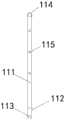
图1为本发明作用于钉棒带有活动支撑臂的寰枢椎脱位后路复位器的结构示意图;1 is a schematic structural diagram of a posterior atlantoaxial dislocation reducer acting on a screw rod with a movable support arm according to the present invention;
图2为本发明支撑杆的结构示意图;Fig. 2 is the structural representation of the support rod of the present invention;
图3为本发明活动杆结构示意图;Fig. 3 is the structure schematic diagram of the movable rod of the present invention;
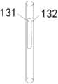
图4为本发明固定管结构示意图;Fig. 4 is the structural schematic diagram of the fixed pipe of the present invention;
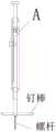
图5为支撑臂的结构示意图;5 is a schematic structural diagram of a support arm;
图6为图5中A处放大图;Fig. 6 is the enlarged view of A place in Fig. 5;
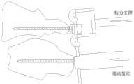
图7为钩手臂和支撑臂对脱位的椎骨进行复位时,固定和位移示意图。Fig. 7 is a schematic diagram of fixation and displacement when the hook arm and the support arm reposition the dislocated vertebra.
1支撑臂;11支撑杆;111连接杆;112支撑部;113弧形开口;114凹腔;115螺纹通孔;12活动杆;121卡入端;122第一螺杆;123螺帽;13固定管;131可视区域;132刻度;2 第一支架;3第二支架;4钩手臂;41钩手;42钩子;5手柄端;6第二螺杆;7限位螺母。1 support arm; 11 support rod; 111 connecting rod; 112 support part; 113 arc opening; 114 cavity; 115 threaded through hole; 12 movable rod; 121 snap-in end; 122 first screw; 123 nut; Tube; 131 visual area; 132 scale; 2 first bracket; 3 second bracket; 4 hook arm; 41 hook hand; 42 hook; 5 handle end; 6 second screw; 7 limit nut.
具体实施方式Detailed ways
下面将结合本发明实施例中的附图,对本发明实施例中的技术方案进行清楚、完整地描述,显然,所描述的实施例仅仅是本发明一部分实施例,而不是全部的实施例。基于本发明中的实施例,本领域普通技术人员在没有作出创造性劳动前提下所获得的所有其他实施例,都属于本发明保护的范围。The technical solutions in the embodiments of the present invention will be clearly and completely described below with reference to the accompanying drawings in the embodiments of the present invention. Obviously, the described embodiments are only a part of the embodiments of the present invention, but not all of the embodiments. Based on the embodiments of the present invention, all other embodiments obtained by those of ordinary skill in the art without creative efforts shall fall within the protection scope of the present invention.
如图1-7所述,一种作用于钉棒带有活动支撑臂的寰枢椎脱位后路复位器,具有呈夹子状限位架,所述夹子状限位架具有第一支架2和第二支架3,所述第一支架2与第二支架3 于中部交点处交叉连接,第一支架2和第二支架3的尾端作为手柄端5,第一支架2的首端安装支撑臂,用于对椎骨推进复位;第二支架3的首端安装钩手臂4;支撑臂1包括固定管13、活动杆12及起推进复位作用的支撑杆11,所述固定管13安装在第一支架2的首端,所述活动杆12贯穿所述固定管13,并与支撑杆11活动连接;所述钩手臂4设有固定在第二支架3首端的钩手41,用于勾紧寰椎处螺钉两侧的钉棒。As shown in Figures 1-7, a posterior atlantoaxial dislocation reducer acting on a screw rod with a movable support arm has a clip-shaped limit frame, and the clip-shaped limit frame has a first bracket 2 and a The
第一支架2手柄端5与第二支架3手柄端5之间设有限位装置,限位装置包括第二螺杆 6和两个限位螺母7,第二螺杆6一端通过连接件固定在第二支架3的手柄端5上,对应地,第一支架2的手柄端5上设有通孔,第二螺杆6的另一端依次穿过一个限位螺母7、通孔和另一个限位螺母7,通过两个限位螺母7限定第一支架2的手柄端5在第二螺杆6上的位置,从而对两个手柄端5之间的距离起到限位效果;A limit device is provided between the handle end 5 of the first bracket 2 and the handle end 5 of the
进一步的,手柄端5为使用过程中的手持部分,通过手柄端5调节支撑臂1与钩手臂4 的间隔距离,然后再旋转两个限位螺母7至第一支架2手柄端5的两侧,对第一支架2的位置进行固定,确保在使用过程中支撑臂与钩手臂4之前的间隔距离是固定的,由于每个人的每块椎骨之间的距离都不是固定的,所以这样可以调节臂手间距离的方式,适用性广,可以适用多种不同的手术情况。Further, the handle end 5 is the hand-held part during use, and the distance between the
进一步的,第一支架2的首端相对于第一支架2具有一定角度α的弯折,对应地,所述第二支架3的首端相对于第二支架3具有一定角度β的弯折;所述第一支架2首端的弯折方向与第二支架3首端的弯折方向相同;所述α或β的取值范围为45°-180°;所述α=β;由于每个医生的手术习惯不同或者是手术场景不同等因素,不同的支架弯折角度可以适应不同的需求。Further, the head end of the first bracket 2 is bent at a certain angle α relative to the first bracket 2, and correspondingly, the head end of the
进一步的,支撑杆11包括起推进复位作用的支撑部112及用于连接所述活动杆12的连接杆111,所述支撑部112与所述连接杆111首端连接,所述活动杆12与所述连接杆111末端连接;所述固定管13套设在活动杆12和连接杆111上,用于限制活动杆12与连接杆111的活动方向;所述活动杆12通过连接杆111带动支撑部112前推,实现椎骨后路复位。Further, the support rod 11 includes a
该作用于钉棒带有活动支撑臂的寰枢椎脱位后路复位器,第一支架2与固定管13、第二支架3与钩手臂4为一体结构,一体结构受力更均匀,增加使用过程中的稳定性。The posterior atlantoaxial dislocation reducer acting on the screw rod with movable support arm has an integrated structure of the first bracket 2 and the fixed tube 13, the
进一步的,钩手41包括用于勾住钉棒的钩子42,钩子42优选地为2个,钩手41末端与第二支架3固定连接,钩子42选用2个才能使其受力更平衡,达到稳定拉动效果,且2个钩子42需要间隔一定距离,间隔距离大于螺钉U形槽的宽度,间隔距离可以根据不同的螺钉规格或者是不同的手术情况进行调整。Further, the hook handle 41 includes hooks 42 for hooking the nail rod, preferably two hooks 42, the end of the hook handle 41 is fixedly connected with the
进一步的,连接杆111末端设有凹腔114;所述活动杆12包括用于拧入所述固定管13 的第一螺杆122,所述第一螺杆122首端设有与所述凹腔114相适配且用于卡入凹腔114的卡入端121,通过卡入端121与凹腔114的配合,将第一螺杆122首端与连接杆111末端活动连接;所述第一螺杆122末端设有用于旋转活动杆12的螺帽123;通过螺帽123带动第一螺杆122旋转,使活动杆12在所述固定管13内作旋进或旋出的移动,从而通过所述连接杆111 带动支撑部112作前推动作。Further, the end of the connecting
进一步的,连接杆111与所述固定管13之间设有限位结构,防止所述连接杆111在所述固定管13内发生转动;Further, a limit structure is provided between the connecting
所述限位结构为:连接杆111一侧设有至少一个螺纹通孔115,连接杆111一侧设有至少一个螺纹通孔115,可以是多个螺丝通孔,若有多个螺丝通孔根据不同的推进距离将螺丝拧入不同的螺纹通孔115,螺丝通过可视区域131拧入螺纹通孔115后,通过可视区域131的开口形状对螺丝的卡位限制连接杆111无法在固定管13内转动;这种限位结构简单,生产难度低。The limiting structure is as follows: one side of the connecting
进一步的,固定管13上还设有用于观测活动杆12移动距离的可视区域131和刻度132;透过可视区域131可以观察到在固定管13内部的活动杆12移动的距离,即是推动杆的移动距离,可以直观的看出椎骨的复位距离。Further, the fixed tube 13 is also provided with a
进一步的,支撑部112设有用于避开螺钉头部的弧形凹槽,所述弧形凹槽的槽壁上设有至少两个弧形开口113,用于卡设在钉棒上,使支撑部112可以卡入钉棒,在钉棒上进行支撑或者推进;弧形开口113还可以为四个,可以适应不同角度的钉棒;将支撑部112置于枢椎处的钉棒上,使弧形凹槽对应螺杆头部,弧形开口113对应于螺杆头部伸出的钉棒进行卡位支撑,可以通过旋转螺帽123的话就可以通过活动杆12带动连接杆111在固定管13内进行伸出活动,进而与钩手41形成相互作用力的关系,将脱位椎骨进行复位。Further, the
具体使用时:观测脱位的寰椎和枢椎的位置关系,以此调节手柄端5使钩手臂4与支撑臂1之间的距离适配寰椎与枢椎的距离,调整好钩手臂4与支撑臂1之间的距离后,将两个限位螺母7拧至第一支架2手柄端5的两侧,以此固定第一支架2,再将螺丝穿过可视区域131拧入螺纹通孔115限制连接杆111在固定管13内的转动;接着手持手柄端5将钩手臂4 深入脱位的寰椎后弓处,使两个钩子42分别置于寰椎螺钉的钉槽两侧勾紧钉棒,然后将支撑部112向前推进,支撑部112的弧形凹槽对应于枢椎处的螺杆头部,然后将弧形开口113对应于钉棒伸出处进行卡位支撑,然后旋转活动杆12的螺母使活动杆12在固定管13内移动,可以对枢椎处钉棒产生向前推移的复位力量,使寰枢椎产生相对运动,即向前直接推移枢椎,向后间接提拉寰椎达到复位的效果,同时可以通过可视区域131控制复位距离;完成复位后,锁紧寰枢椎螺钉的螺母;调节螺帽123使钩手41伸出钉棒,便可以手持手柄端5取出本发明带作用于钉棒带有活动支撑臂的寰枢椎脱位后路复位器。In specific use: observe the positional relationship between the dislocated atlas and the axis, and adjust the handle end 5 to make the distance between the hook arm 4 and the
以上所述仅为本发明的较佳实施例而已,并不用以限制本发明,凡在本发明的精神和原则之内,所作的任何修改、等同替换、改进等,均应包含在本发明的保护范围之内。The above descriptions are only preferred embodiments of the present invention, and are not intended to limit the present invention. Any modification, equivalent replacement, improvement, etc. made within the spirit and principle of the present invention shall be included in the scope of the present invention. within the scope of protection.
Claims (9)
Priority Applications (1)
| Application Number | Priority Date | Filing Date | Title |
|---|---|---|---|
| CN202010049089.6ACN111329567A (en) | 2020-01-16 | 2020-01-16 | Atlantoaxial dislocation posterior repositor with movable supporting arm acting on nail rod |
Applications Claiming Priority (1)
| Application Number | Priority Date | Filing Date | Title |
|---|---|---|---|
| CN202010049089.6ACN111329567A (en) | 2020-01-16 | 2020-01-16 | Atlantoaxial dislocation posterior repositor with movable supporting arm acting on nail rod |
Publications (1)
| Publication Number | Publication Date |
|---|---|
| CN111329567Atrue CN111329567A (en) | 2020-06-26 |
Family
ID=71173742
Family Applications (1)
| Application Number | Title | Priority Date | Filing Date |
|---|---|---|---|
| CN202010049089.6APendingCN111329567A (en) | 2020-01-16 | 2020-01-16 | Atlantoaxial dislocation posterior repositor with movable supporting arm acting on nail rod |
Country Status (1)
| Country | Link |
|---|---|
| CN (1) | CN111329567A (en) |
Cited By (2)
| Publication number | Priority date | Publication date | Assignee | Title |
|---|---|---|---|---|
| CN114366263A (en)* | 2022-01-26 | 2022-04-19 | 中国人民解放军南部战区总医院 | A novel occipital fixation structure of posterior cervical spine with reduction function |
| CN114533242A (en)* | 2022-02-28 | 2022-05-27 | 中国人民解放军南部战区总医院 | Skull base depression resetting device |
Citations (5)
| Publication number | Priority date | Publication date | Assignee | Title |
|---|---|---|---|---|
| CN1545984A (en)* | 2003-12-17 | 2004-11-17 | 尹庆水 | Reposition device for atlas |
| KR20080035999A (en)* | 2007-02-06 | 2008-04-24 | 신세스 게엠바하 | Spinal rod insertion device |
| CN208130039U (en)* | 2017-06-21 | 2018-11-23 | 马向阳 | A kind of fixed device of novel arch of posterior atlas |
| CN109247979A (en)* | 2018-09-28 | 2019-01-22 | 中国人民解放军南部战区总医院 | A kind of atlantoaxial dislocation way of escape restorer |
| CN212118269U (en)* | 2020-01-16 | 2020-12-11 | 中国人民解放军南部战区总医院 | Atlantoaxial dislocation posterior repositor with movable supporting arm acting on nail rod |
- 2020
- 2020-01-16CNCN202010049089.6Apatent/CN111329567A/enactivePending
Patent Citations (5)
| Publication number | Priority date | Publication date | Assignee | Title |
|---|---|---|---|---|
| CN1545984A (en)* | 2003-12-17 | 2004-11-17 | 尹庆水 | Reposition device for atlas |
| KR20080035999A (en)* | 2007-02-06 | 2008-04-24 | 신세스 게엠바하 | Spinal rod insertion device |
| CN208130039U (en)* | 2017-06-21 | 2018-11-23 | 马向阳 | A kind of fixed device of novel arch of posterior atlas |
| CN109247979A (en)* | 2018-09-28 | 2019-01-22 | 中国人民解放军南部战区总医院 | A kind of atlantoaxial dislocation way of escape restorer |
| CN212118269U (en)* | 2020-01-16 | 2020-12-11 | 中国人民解放军南部战区总医院 | Atlantoaxial dislocation posterior repositor with movable supporting arm acting on nail rod |
Cited By (2)
| Publication number | Priority date | Publication date | Assignee | Title |
|---|---|---|---|---|
| CN114366263A (en)* | 2022-01-26 | 2022-04-19 | 中国人民解放军南部战区总医院 | A novel occipital fixation structure of posterior cervical spine with reduction function |
| CN114533242A (en)* | 2022-02-28 | 2022-05-27 | 中国人民解放军南部战区总医院 | Skull base depression resetting device |
Similar Documents
| Publication | Publication Date | Title |
|---|---|---|
| JP4146500B2 (en) | Device for fixing the spine | |
| US5478340A (en) | Vertebral column implant and repositioning instrument | |
| US6416515B1 (en) | Spinal fixation system | |
| CN211633536U (en) | Atlantoaxial dislocation posterior repositor with movable arm | |
| US20060293692A1 (en) | Instruments and methods for manipulating a spinal fixation element | |
| US20070161998A1 (en) | Instruments and Methods For Manipulating A Spinal Rod | |
| CN111329567A (en) | Atlantoaxial dislocation posterior repositor with movable supporting arm acting on nail rod | |
| JP6192661B2 (en) | Improved spinal fixation system | |
| CN109247979B (en) | Atlantoaxial dislocation posterior restorer | |
| CN107260281B (en) | A Posterior Cervical Internal Fixation Apparatus for Reduction of Skull Base Depression | |
| CN211674502U (en) | Atlantoaxial dislocation posterior repositor with double movable arms acting on nail rod | |
| CN111134822A (en) | A posterior reduction device for atlantoaxial dislocation acting on a screw rod with double movable arms | |
| CN111134819B (en) | Atlantoaxial dislocation posterior restorer with movable arm | |
| CN212118269U (en) | Atlantoaxial dislocation posterior repositor with movable supporting arm acting on nail rod | |
| WO2021143808A1 (en) | Atlantoaxial dislocation posterior position-reset device having dual movable arms acting on nail rods | |
| CN111134821A (en) | Atlantoaxial dislocation posterior repositor with movable hook arm acting on nail rod | |
| WO2006022940A2 (en) | Facial osteodistraction device | |
| CN212015744U (en) | Atlantoaxial dislocation posterior repositor with movable hook arm acting on nail rod | |
| CN112971958B (en) | External mandibular distractor | |
| CN111134820A (en) | A posterior reduction device for atlantoaxial dislocation with movable support arm | |
| CN211911769U (en) | Atlantoaxial dislocation posterior repositor with movable supporting arm | |
| JPWO2019132005A1 (en) | Spine fixation system | |
| CN211911768U (en) | Atlantoaxial dislocation posterior repositor with movable clamping arms | |
| CN111110338A (en) | A posterior reduction device for atlantoaxial dislocation with movable clip arm | |
| WO2021143807A1 (en) | Atlantoaxial dislocation posterior repositor having moving arms |
Legal Events
| Date | Code | Title | Description |
|---|---|---|---|
| PB01 | Publication | ||
| PB01 | Publication | ||
| SE01 | Entry into force of request for substantive examination | ||
| SE01 | Entry into force of request for substantive examination | ||
| TA01 | Transfer of patent application right | ||
| TA01 | Transfer of patent application right | Effective date of registration:20201022 Address after:Yuexiu District Guangzhou City, Guangdong province 510000 Liuhua Road No. 111 Applicant after:PEOPLE'S LIBERATION ARMY SOUTHERN THEATER GENERAL Hospital Address before:Guangzhou City, Guangdong province 510010 Liuhua Road No. 111 Applicant before:Ma Haotian | |
| RJ01 | Rejection of invention patent application after publication | ||
| RJ01 | Rejection of invention patent application after publication | Application publication date:20200626 |