CN111328228A - Internet of things device solid line connection cabinet - Google Patents
Internet of things device solid line connection cabinetDownload PDFInfo
- Publication number
- CN111328228A CN111328228ACN202010154176.8ACN202010154176ACN111328228ACN 111328228 ACN111328228 ACN 111328228ACN 202010154176 ACN202010154176 ACN 202010154176ACN 111328228 ACN111328228 ACN 111328228A
- Authority
- CN
- China
- Prior art keywords
- force
- core
- solid line
- external
- internet
- Prior art date
- Legal status (The legal status is an assumption and is not a legal conclusion. Google has not performed a legal analysis and makes no representation as to the accuracy of the status listed.)
- Granted
Links
- 238000005096rolling processMethods0.000claimsdescription14
- 210000001503jointAnatomy0.000claims3
- 238000010079rubber tappingMethods0.000claims2
- 230000006855networkingEffects0.000claims1
- 230000003139buffering effectEffects0.000abstractdescription5
- 238000000926separation methodMethods0.000abstract1
- 238000010586diagramMethods0.000description6
- 230000000694effectsEffects0.000description4
- 239000000463materialSubstances0.000description4
- 230000005540biological transmissionEffects0.000description2
- 230000009286beneficial effectEffects0.000description1
- 239000002775capsuleSubstances0.000description1
- 230000007423decreaseEffects0.000description1
- 230000007812deficiencyEffects0.000description1
- 238000001125extrusionMethods0.000description1
- 238000009434installationMethods0.000description1
- 238000002955isolationMethods0.000description1
- 238000000034methodMethods0.000description1
- 238000005192partitionMethods0.000description1
- 239000007787solidSubstances0.000description1
Images


Classifications
- H—ELECTRICITY
- H05—ELECTRIC TECHNIQUES NOT OTHERWISE PROVIDED FOR
- H05K—PRINTED CIRCUITS; CASINGS OR CONSTRUCTIONAL DETAILS OF ELECTRIC APPARATUS; MANUFACTURE OF ASSEMBLAGES OF ELECTRICAL COMPONENTS
- H05K5/00—Casings, cabinets or drawers for electric apparatus
- H05K5/02—Details
- H05K5/0247—Electrical details of casings, e.g. terminals, passages for cables or wiring
- H—ELECTRICITY
- H05—ELECTRIC TECHNIQUES NOT OTHERWISE PROVIDED FOR
- H05K—PRINTED CIRCUITS; CASINGS OR CONSTRUCTIONAL DETAILS OF ELECTRIC APPARATUS; MANUFACTURE OF ASSEMBLAGES OF ELECTRICAL COMPONENTS
- H05K7/00—Constructional details common to different types of electric apparatus
- H05K7/14—Mounting supporting structure in casing or on frame or rack
- H05K7/1438—Back panels or connecting means therefor; Terminals; Coding means to avoid wrong insertion
- H05K7/1447—External wirings; Wiring ducts; Laying cables
- H05K7/1448—External wirings; Wiring ducts; Laying cables with connections to the front board
Landscapes
- Engineering & Computer Science (AREA)
- Microelectronics & Electronic Packaging (AREA)
- Pivots And Pivotal Connections (AREA)
Abstract
Translated fromChinese
Description
Translated fromChinese技术领域technical field
本发明属于物联网领域,更具体地说,尤其是涉及到一种物联网装置实线衔接柜。The invention belongs to the field of Internet of Things, and more specifically, relates to a solid-line connection cabinet for Internet of Things devices.
背景技术Background technique
物联网的装置柜内部,会安装有控制芯片与控制端等等的电路装置,在有限的空间内,之间的安装布局有序且较近,之间由导线进行衔接,并且也会有与内部通过实线衔接的部位。Inside the device cabinet of the Internet of Things, circuit devices such as control chips and control terminals will be installed. In a limited space, the installation layout between them is orderly and close. Parts connected by solid lines inside.
基于上述本发明人发现,现有的物联网装置柜主要存在以下几点不足,比如:Based on the above findings of the present inventors, the existing IoT device cabinets mainly have the following deficiencies, such as:
在外部实线通过衔接口与内部接触时,外接线置于外侧部位,在有外力对其转动或者触碰到时,内部的衔接线会有所抵触到附近的衔接线,当线接触过近较容易出现短路的现象。When the outer solid line contacts the inner part through the connection port, the outer line is placed on the outer part. When there is an external force to rotate or touch it, the inner connection line will conflict with the nearby connection line. When the line is too close Short circuits are more likely to occur.
因此需要提出一种物联网装置实线衔接柜。Therefore, it is necessary to propose a solid-line connection cabinet for IoT devices.
发明内容SUMMARY OF THE INVENTION
为了解决上述技术在外部实线通过衔接口与内部接触时,外接线置于外侧部位,在有外力对其转动或者触碰到时,内部的衔接线会有所抵触到附近的衔接线,当线接触过近较容易出现短路的现象的问题。In order to solve the above-mentioned technology, when the external solid line contacts the interior through the connecting port, the external line is placed on the outer part. When an external force rotates or touches it, the internal connecting line will interfere with the nearby connecting line. When The problem of short circuit phenomenon is more likely to occur when the wire is too close.
本发明一种物联网装置实线衔接柜的目的与功效,由以下具体技术手段所达成:The purpose and effect of a solid-line connection cabinet of an Internet of Things device of the present invention are achieved by the following specific technical means:
其结构包括外接口、主托板、外控端、装置柜箱、限置板。Its structure includes an external interface, a main support board, an external control terminal, a device cabinet box, and a limit board.
所述主托板焊接于限置板外表面,所述限置板与装置柜箱为一体化结构,所述外接口贯穿于主托板内部,所述外控端与主托板安装于同一个垂直面上。The main support board is welded on the outer surface of the limiting board, the limiting board and the device cabinet are an integrated structure, the external interface runs through the interior of the main support board, and the external control end and the main support board are installed in the same structure. a vertical plane.
作为本发明的进一步改进,所述外接口包括凹接口、外抵壳、中接芯、隔力抵环,所述凹接口嵌入于外抵壳内部,所述中接芯贯穿于外抵壳内部,所述隔力抵环抵在外抵壳与中接芯相连接,所述凹接口呈凹字型结构。As a further improvement of the present invention, the outer interface includes a concave interface, an outer abutment shell, a middle connection core, and a force-isolating abutment ring, the female interface is embedded in the outer abutment shell, and the middle connection core penetrates through the outer abutment shell. , the force-isolating abutting ring is connected with the middle connecting core against the outer abutting shell, and the concave interface is in a concave-shaped structure.
作为本发明的进一步改进,所述隔力抵环包括托固条、匀力格、节固点、中口,所述节固点嵌入于匀力格内部,所述匀力格与托固条间隔抵触,所述中口安装于托固条内部且位于同一轴心上,所述托固条设有四个且呈圆环形均匀分布,所述节固点设有四个。As a further improvement of the present invention, the force isolating ring includes a supporting strip, a uniform grid, a joint fixing point, and a middle mouth, the node securing point is embedded in the uniform grid, and the uniform grid is connected to the supporting strip. The middle openings are installed inside the support bars and are located on the same axis, the support bars are provided with four and are evenly distributed in an annular shape, and the node fixation points are provided with four.
作为本发明的进一步改进,所述托固条包括托芯条、随力层、抵芯,所述托芯条嵌入于随力层内部,所述随力层与抵芯相抵触,所述抵芯为凹弧口形态,所述托芯条由橡胶材质所制成,具有一定的拉扯性。As a further improvement of the present invention, the support strip includes a core strip, a force-compliant layer, and a core, the core-support strip is embedded in the force-compliant layer, the force-compliant layer is in conflict with the core, and the abutment The core is in the shape of a concave arc, and the core support bar is made of rubber material and has a certain pulling property.
作为本发明的进一步改进,所述外抵壳包括压力囊、匀压球、抵块、助调头、抵层,所述匀压球设于压力囊侧方,所述匀压球安装于抵块与抵层之间,所述助调头与抵块相连接,所述匀压球为球体结构,所述抵层正视为三角形结构。As a further improvement of the present invention, the outer abutment shell includes a pressure bag, a pressure equalizing ball, a resistance block, an adjustment head, and an abutment layer, the pressure equalization ball is arranged on the side of the pressure bag, and the pressure equalization ball is installed on the abutment block. Between the abutment layer, the U-turn head is connected with the abutment block, the equalizing ball has a spherical structure, and the abutment layer is regarded as a triangular structure.
作为本发明的进一步改进,所述助调头包括主抵弧、缓芯、受面,所述受面抵在缓芯下表面,所述缓芯远离受面的一端与主抵弧相连接,所述受面呈半弧形结构,所述主抵弧为半圆形结构。As a further improvement of the present invention, the U-turn head includes a main contact arc, a slow core, and a receiving surface, the receiving surface abuts on the lower surface of the slow core, and the end of the slow core away from the receiving surface is connected with the main contact arc, so The receiving surface is in a semi-arc structure, and the main contact arc is in a semi-circular structure.
作为本发明的进一步改进,所述主抵弧包括滚球、护力面、内位沟,所述内位沟嵌入于护力面内部,所述护力面抵在滚球外表面,所述滚球为球体结构且均匀排列分布,所述护力面为三角体间隔分布。As a further improvement of the present invention, the main contact arc includes a rolling ball, a force protection surface, and an inner position groove, the inner position groove is embedded in the inner position of the force protection surface, the force protection surface abuts on the outer surface of the rolling ball, and the The rolling balls have a spherical structure and are evenly arranged and distributed, and the force-protecting surfaces are distributed at intervals of triangular bodies.
作为本发明的进一步改进,所述抵层包括集力球、后兜体、胶边,所述胶边贴合于集力球外表面,所述集力球嵌入于后兜体内部,所述集力球为球体结构且呈水平方向均匀分布,所述胶边由胶体材质所制成,具有一定的拉扯性。As a further improvement of the present invention, the abutting layer includes a power-gathering ball, a back pocket body, and a rubber edge, the rubber edge is attached to the outer surface of the power-gathering ball, the power-gathering ball is embedded in the back pocket body, and the power-gathering ball is embedded inside the back pocket body. The power-gathering ball has a spherical structure and is evenly distributed in the horizontal direction. The rubber edge is made of colloidal material and has a certain pulling property.
与现有技术相比,本发明具有如下有益效果:Compared with the prior art, the present invention has the following beneficial effects:
1.其外接实线将会置入凹接口内部,由外抵壳抵在最外侧,抵芯的弧面主要用来抵触中接芯表面部位,让外接线与内接线有一个衔接的传输点,让之间的受力托固条之间的匀力格起到隔力回绷的作用,在外接线需要进行一定程度上进行调整时,将会先把内部的导线进行固定,使其不会受到转动的影响。1. The external solid line will be placed inside the concave interface, and the outer contact shell will be pressed against the outermost side. The arc surface of the contact core is mainly used to abut the surface of the middle contact core, so that the external wiring and the internal wiring have a connecting transmission point. , so that the uniform force between the force-retaining bars between them can play the role of isolating the force and stretching back. When the external wiring needs to be adjusted to a certain extent, the internal wires will be fixed first so that they will not be affected by rotation.
2.将会大面积的托于物体表面,在衔接线转动时,其集力球将会根据力的转动有所活动,使其压力囊与匀压球能够有所压缩缓冲,延伸开缓冲的力,并且逐渐递减,让内部的受面起到固定托附的作用,其衔接线抵在主抵弧上进行活动的同时,能够在外接线需要调整时,对其起到辅助与一定范围内的转动。2. It will support a large area on the surface of the object. When the connecting line rotates, the force-concentrating ball will move according to the rotation of the force, so that the pressure bag and the pressure-equalizing ball can be compressed and buffered, and the buffering can be extended. The force is gradually reduced, so that the internal receiving surface plays a role of fixing and attaching. While the connecting line is moving against the main contact arc, it can assist and support the external wiring when it needs to be adjusted within a certain range. turn.
附图说明Description of drawings
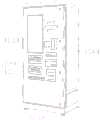
图1为本发明一种物联网装置实线衔接柜的结构示意图。FIG. 1 is a schematic structural diagram of a solid line connection cabinet of an IoT device according to the present invention.
图2为本发明一种外接口的右视内部结构示意图。FIG. 2 is a schematic diagram of the internal structure of an external interface of the present invention as viewed from the right side.
图3为本发明一种隔力抵环的左视内部结构示意图。FIG. 3 is a left-view internal structure diagram of a force-isolating abutment ring of the present invention.
图4为本发明一种托固条的正视内部结构示意图。FIG. 4 is a schematic diagram of the front view of the internal structure of a holding bar according to the present invention.
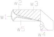
图5为本发明一种外抵壳的正视内部结构示意图。FIG. 5 is a schematic view of the front view of the internal structure of an outer contact shell of the present invention.
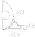
图6为本发明一种助调头的正视内部结构示意图。FIG. 6 is a schematic view of the internal structure of a U-turn assistant head according to the present invention.
图7为本发明一种主抵弧的立体结构示意图。FIG. 7 is a schematic three-dimensional structure diagram of a main contact arc of the present invention.
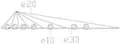
图8为本发明一种抵层的正视内部结构示意图。FIG. 8 is a schematic diagram of the front view of the internal structure of a backing layer according to the present invention.
图中:外接口-t011、主托板-t022、外控端-t033、装置柜箱-t044、限置板-t055、凹接口-q11、外抵壳-q22、中接芯-q33、隔力抵环-q44、托固条-110、匀力格-220、节固点-330、中口-440、托芯条-h11、随力层-h22、抵芯-h33、压力囊-w1、匀压球-w2、抵块-w3、助调头-w4、抵层-w5、主抵弧-z01、缓芯-z02、受面-z03、滚球-c11、护力面-c22、内位沟-c33、集力球-e10、后兜体-e20、胶边-e30。In the figure: external interface-t011, main support plate-t022, external control terminal-t033, device cabinet box-t044, limit plate-t055, concave interface-q11, outer contact shell-q22, central connection core-q33, partition Force contact ring - q44, support strip - 110, uniform strength grid - 220, joint anchor point - 330, middle mouth - 440, core support strip - h11, force layer - h22, core support - h33, pressure bladder - w1 , Uniform pressure ball-w2, contact block-w3, auxiliary U-turn-w4, contact layer-w5, main contact arc-z01, slow core-z02, receiving surface-z03, rolling ball-c11, force-protecting surface-c22, inner Bit groove - c33, power collection ball - e10, back pocket - e20, rubber edge - e30.
具体实施方式Detailed ways
以下结合附图对本发明做进一步描述:The present invention will be further described below in conjunction with the accompanying drawings:
实施例1:Example 1:
如附图1至附图4所示:As shown in accompanying drawings 1 to 4:
本发明提供一种物联网装置实线衔接柜,其结构包括外接口t011、主托板t022、外控端t033、装置柜箱t044、限置板t055。The present invention provides a solid line connection cabinet for an Internet of Things device, the structure of which includes an external interface t011, a main support board t022, an external control terminal t033, a device cabinet box t044, and a limiting board t055.
所述主托板t022焊接于限置板t055外表面,所述限置板t055与装置柜箱t044为一体化结构,所述外接口t011贯穿于主托板t022内部,所述外控端t033与主托板t022安装于同一个垂直面上。The main support board t022 is welded to the outer surface of the limiting board t055. The limiting board t055 and the device cabinet box t044 are integrated structures. The external interface t011 penetrates through the main support board t022. It is installed on the same vertical plane as the main pallet t022.
其中,所述外接口t011包括凹接口q11、外抵壳q22、中接芯q33、隔力抵环q44,所述凹接口q11嵌入于外抵壳q22内部,所述中接芯q33贯穿于外抵壳q22内部,所述隔力抵环q44抵在外抵壳q22与中接芯q33相连接,所述凹接口q11呈凹字型结构,所述凹接口q11让外接线能够更好的与内部衔接,外抵壳q22对所置放的外接线进行固定,中接芯q33让外接线与内接线有一个衔接的传输点。The outer interface t011 includes a female interface q11, an outer contact shell q22, a middle connection core q33, and a force-isolating abutment ring q44, the female interface q11 is embedded in the outer contact shell q22, and the middle connection core q33 penetrates through the outside Inside the contact shell q22, the force isolation ring q44 is connected to the outer contact shell q22 and the middle contact core q33. The female interface q11 has a concave structure, and the female interface q11 allows the external wiring to better connect with the internal Connecting, the outer contact shell q22 fixes the placed outer wire, and the middle connection core q33 allows the outer wire and the inner wire to have a connecting transmission point.
其中,所述隔力抵环q44包括托固条110、匀力格220、节固点330、中口440,所述节固点330嵌入于匀力格220内部,所述匀力格220与托固条110间隔抵触,所述中口440安装于托固条110内部且位于同一轴心上,所述托固条110设有四个且呈圆环形均匀分布,所述节固点330设有四个,所述匀力格220间隔开两侧所承受外力的部位,让其不会过分的摆动,并且起到缓冲的作用,节固点330巩固整圈的固力分节点,托固条110对内部所抵触的物体进行一定力的托附。Wherein, the force isolating ring q44 includes a holding
其中,所述托固条110包括托芯条h11、随力层h22、抵芯h33,所述托芯条h11嵌入于随力层h22内部,所述随力层h22与抵芯h33相抵触,所述抵芯h33为凹弧口形态,所述托芯条h11由橡胶材质所制成,具有一定的拉扯性,所述托芯条h11在所衔接部位外层受力时,能够起到限制力的承受面积,并且具有拉扯的作用,抵芯h33主要承受外侧的力,起到聚集的作用。The
其中,所述外抵壳q22包括压力囊w1、匀压球w2、抵块w3、助调头w4、抵层w5,所述匀压球w2设于压力囊w1侧方,所述匀压球w2安装于抵块w3与抵层w5之间,所述助调头w4与抵块w3相连接,所述匀压球w2为球体结构,所述抵层w5正视为三角形结构,所述抵层w5大面积的抵触外力,并且将其往内部方向聚集,压力囊w1在周围层受力时,起到挤压防护的作用,匀压球w2延伸开缓冲的力,并且逐渐递减,助调头w4对所抵触的部位起到限位的作用。Wherein, the outer contact shell q22 includes a pressure bladder w1, a pressure equalizing ball w2, abutting block w3, a U-turn head w4, and a contact layer w5. Installed between the abutment block w3 and the abutment layer w5, the U-turn head w4 is connected to the abutment block w3, the equalizing ball w2 is a spherical structure, the abutment layer w5 is viewed as a triangular structure, and the abutment layer w5 is large. The area resists the external force, and gathers it inward. When the pressure capsule w1 is subjected to force on the surrounding layer, it plays a role of extrusion protection. The uniform pressure ball w2 extends the buffering force and gradually decreases. The conflicting part acts as a limiter.
本实施例的具体使用方式与作用:The specific usage mode and function of this embodiment:
本发明中,当外接头需要接入物联网的控制端时,将需要通过外接口t011进行衔接于内部,其外接实线将会置入凹接口q11内部,由外抵壳q22抵在最外侧,在外接实线需转动调整且中接芯q33置于内部中端时,由托固条110抵在中接芯q33外侧表面,抵芯h33的弧面主要用来抵触中接芯q33表面部位,在外接实线有所拖动中接芯q33时,其抵芯h33将会托住所承受的力,往内施展,让托芯条h11得到适当的拉扯,由随力层h22起到跟随作用,让之间的受力托固条110之间的匀力格220起到隔力回绷的作用,让衔接线在转动的时候,中接芯q33能够稳固的固定住。In the present invention, when the external connector needs to be connected to the control terminal of the Internet of Things, it will need to be connected to the inside through the external interface t011, and the external solid line will be placed inside the concave interface q11, and the outermost shell q22 will be pressed against the outermost side. , when the external solid line needs to be rotated and adjusted and the middle connecting core q33 is placed at the inner middle end, the
实施例2:Example 2:
如附图5至附图8所示:As shown in accompanying drawings 5 to 8:
其中,所述助调头w4包括主抵弧z01、缓芯z02、受面z03,所述受面z03抵在缓芯z02下表面,所述缓芯z02远离受面z03的一端与主抵弧z01相连接,所述受面z03呈半弧形结构,所述主抵弧z01为半圆形结构,所述主抵弧z01主要用来抵触外物,受面z03对固定面进行抵触,并且在后端受力时,起到固力作用,缓芯z02置于固定面与受力面之间,起到缓冲的作用。The U-turn head w4 includes a main contact arc z01, a slow core z02, and a receiving surface z03, the receiving surface z03 abuts on the lower surface of the slow core z02, and one end of the slow core z02 away from the receiving surface z03 is connected to the main contact arc z01 Connected, the receiving surface z03 is in a semi-arc structure, the main contact arc z01 is a semi-circular structure, the main contact arc z01 is mainly used to resist foreign objects, the receiving surface z03 collides with the fixed surface, and is in contact with the fixed surface. When the rear end is stressed, it acts as a solid force, and the buffer core z02 is placed between the fixed surface and the force surface to play a buffering role.
其中,所述主抵弧z01包括滚球c11、护力面c22、内位沟c33,所述内位沟c33嵌入于护力面c22内部,所述护力面c22抵在滚球c11外表面,所述滚球c11为球体结构且均匀排列分布,所述护力面c22为三角体间隔分布,所述护力面c22对外力起到稳固的承受作用,滚球c11在外抵触力进行抵触受力时,在限定的部位起到滚动作用,内位沟c33限制物体的活动范围。The main contact arc z01 includes a rolling ball c11, a force protection surface c22, and an inner groove c33, the inner groove c33 is embedded inside the force protection surface c22, and the force protection surface c22 abuts against the outer surface of the rolling ball c11 , the rolling ball c11 is a spherical structure and is evenly arranged and distributed, the force protection surface c22 is a triangular body spaced distribution, the force protection surface c22 plays a stable bearing effect on the external force, and the rolling ball c11 resists the external resistance force. When the force is applied, it plays a rolling role in a limited part, and the inner position groove c33 limits the range of motion of the object.
其中,所述抵层w5包括集力球e10、后兜体e20、胶边e30,所述胶边e30贴合于集力球e10外表面,所述集力球e10嵌入于后兜体e20内部,所述集力球e10为球体结构且呈水平方向均匀分布,所述胶边e30由胶体材质所制成,具有一定的拉扯性,所述后兜体e20固定住整体的受力面积,集力球e10在外层受力时,聚集在一定的位置,胶边e30在聚集点进行受力时,起到跟随外力摆动的一定距离拉扯。Wherein, the contact layer w5 includes a power-collecting ball e10, a back pocket e20, and a rubber edge e30, the rubber edge e30 is attached to the outer surface of the power-collecting ball e10, and the power-collecting ball e10 is embedded inside the back pocket body e20 , the force-collecting ball e10 is a spherical structure and is evenly distributed in the horizontal direction, the rubber edge e30 is made of colloidal material and has a certain pulling property, and the back pocket e20 fixes the overall force-bearing area, collecting When the force ball e10 is stressed on the outer layer, it gathers at a certain position, and when the rubber edge e30 is subjected to force at the gathering point, it plays a certain distance pulling following the swing of the external force.
本实施例的具体使用方式与作用:The specific usage mode and function of this embodiment:
本发明中,在衔接线受到外力有所顺着外抵壳q22转动时,对其衔接线所抵触的部位抵层w5,将会大面积的托于物体表面,在衔接线转动时,其集力球e10将会根据力的转动有所活动,并且拖动胶边e30起到回扯的作用,后端的后兜体e20将会聚集外侧所承受的力,从往内进行挤压,使其压力囊w1与匀压球w2能够有所压缩缓冲,在衔接线的端头抵在助调头w4上进行活动时,主抵弧z01将会把所承受到的力对其缓芯z02进行施压,让内部的受面z03起到固定托附的作用,其衔接线抵在主抵弧z01上进行活动的同时,会对滚球c11进行推力,让滚球c11顺着内位沟c33内部进行滚动,来辅助外物不会抵触过硬的力,让衔接线能够在一定范围的情况下进行调整。In the present invention, when the connecting line is rotated along the outer abutment shell q22 by an external force, the abutting layer w5 at the part where the connecting line interferes will be supported on the surface of the object in a large area. The force ball e10 will move according to the rotation of the force, and drag the rubber edge e30 to pull back. The pressure bladder w1 and the pressure equalizing ball w2 can be compressed and buffered. When the end of the connecting line is moved against the U-turn head w4, the main contact arc z01 will exert the force on its buffer core z02. , let the internal receiving surface z03 play the role of fixed support. When the connecting line touches the main contact arc z01 and moves, it will push the rolling ball c11, so that the rolling ball c11 will move along the inner position groove c33. Rolling, to assist foreign objects will not resist the strong force, so that the connecting line can be adjusted within a certain range.
利用本发明所述技术方案,或本领域的技术人员在本发明技术方案的启发下,设计出类似的技术方案,而达到上述技术效果的,均是落入本发明的保护范围。Utilizing the technical solutions of the present invention, or those skilled in the art design similar technical solutions under the inspiration of the technical solutions of the present invention, and achieve the above technical effects, all fall within the protection scope of the present invention.
Claims (8)
Priority Applications (1)
| Application Number | Priority Date | Filing Date | Title |
|---|---|---|---|
| CN202010154176.8ACN111328228B (en) | 2020-03-07 | 2020-03-07 | An IoT device solid line connection cabinet |
Applications Claiming Priority (1)
| Application Number | Priority Date | Filing Date | Title |
|---|---|---|---|
| CN202010154176.8ACN111328228B (en) | 2020-03-07 | 2020-03-07 | An IoT device solid line connection cabinet |
Publications (2)
| Publication Number | Publication Date |
|---|---|
| CN111328228Atrue CN111328228A (en) | 2020-06-23 |
| CN111328228B CN111328228B (en) | 2021-05-18 |
Family
ID=71173344
Family Applications (1)
| Application Number | Title | Priority Date | Filing Date |
|---|---|---|---|
| CN202010154176.8AExpired - Fee RelatedCN111328228B (en) | 2020-03-07 | 2020-03-07 | An IoT device solid line connection cabinet |
Country Status (1)
| Country | Link |
|---|---|
| CN (1) | CN111328228B (en) |
Cited By (1)
| Publication number | Priority date | Publication date | Assignee | Title |
|---|---|---|---|---|
| CN111836496A (en)* | 2020-08-06 | 2020-10-27 | 陈斌 | Thing networking equipment rack |
Citations (14)
| Publication number | Priority date | Publication date | Assignee | Title |
|---|---|---|---|---|
| US20040260198A1 (en)* | 2003-06-18 | 2004-12-23 | Elliott Rothberg | Endoscopic instruments |
| US20050164534A1 (en)* | 2003-03-24 | 2005-07-28 | Che-Yu Li | Interconnection device and system |
| US20060134979A1 (en)* | 2004-12-20 | 2006-06-22 | Henningsen Jimmy C | Coaxial connector with back nut clamping ring |
| JP2014110699A (en)* | 2012-12-03 | 2014-06-12 | Mitsubishi Heavy Ind Ltd | Wire cable assembly |
| CN204305500U (en)* | 2014-12-17 | 2015-04-29 | 贵州天义汽车电器有限公司 | A kind of outlet structure of electric control box |
| CN107796980A (en)* | 2017-10-11 | 2018-03-13 | 江苏士林电气设备有限公司 | A kind of monitoring device of intelligent DC tube type bus |
| CN108382223A (en)* | 2018-01-30 | 2018-08-10 | 谢银泉 | A kind of charging pile with heat dissipation grid based on new energy field |
| CN208015140U (en)* | 2018-02-23 | 2018-10-26 | 南京电研电力自动化股份有限公司 | A kind of anticreep corrosion protection equipment cabinet of Automation of Electric Systems |
| CN108811409A (en)* | 2017-05-04 | 2018-11-13 | 欧姆龙株式会社 | E-machine |
| CN109148213A (en)* | 2018-07-26 | 2019-01-04 | 安徽吉乃尔电器科技有限公司 | The interrupted equipment of modularized vacuum |
| CN208424977U (en)* | 2018-08-07 | 2019-01-22 | 江西华亿香料化工有限公司 | A kind of control cabinet for natural perfume material production |
| CN208462216U (en)* | 2018-08-15 | 2019-02-01 | 深圳市振兴光通信股份有限公司 | The module installation structure of interior case is protected in a kind of intelligence communication |
| CN110459933A (en)* | 2019-08-23 | 2019-11-15 | 陈君辉 | A kind of patching machine for new energy |
| CN110824214A (en)* | 2019-12-06 | 2020-02-21 | 林毓松 | A power meter box fixed assembly external lead wiring device |
- 2020
- 2020-03-07CNCN202010154176.8Apatent/CN111328228B/ennot_activeExpired - Fee Related
Patent Citations (14)
| Publication number | Priority date | Publication date | Assignee | Title |
|---|---|---|---|---|
| US20050164534A1 (en)* | 2003-03-24 | 2005-07-28 | Che-Yu Li | Interconnection device and system |
| US20040260198A1 (en)* | 2003-06-18 | 2004-12-23 | Elliott Rothberg | Endoscopic instruments |
| US20060134979A1 (en)* | 2004-12-20 | 2006-06-22 | Henningsen Jimmy C | Coaxial connector with back nut clamping ring |
| JP2014110699A (en)* | 2012-12-03 | 2014-06-12 | Mitsubishi Heavy Ind Ltd | Wire cable assembly |
| CN204305500U (en)* | 2014-12-17 | 2015-04-29 | 贵州天义汽车电器有限公司 | A kind of outlet structure of electric control box |
| CN108811409A (en)* | 2017-05-04 | 2018-11-13 | 欧姆龙株式会社 | E-machine |
| CN107796980A (en)* | 2017-10-11 | 2018-03-13 | 江苏士林电气设备有限公司 | A kind of monitoring device of intelligent DC tube type bus |
| CN108382223A (en)* | 2018-01-30 | 2018-08-10 | 谢银泉 | A kind of charging pile with heat dissipation grid based on new energy field |
| CN208015140U (en)* | 2018-02-23 | 2018-10-26 | 南京电研电力自动化股份有限公司 | A kind of anticreep corrosion protection equipment cabinet of Automation of Electric Systems |
| CN109148213A (en)* | 2018-07-26 | 2019-01-04 | 安徽吉乃尔电器科技有限公司 | The interrupted equipment of modularized vacuum |
| CN208424977U (en)* | 2018-08-07 | 2019-01-22 | 江西华亿香料化工有限公司 | A kind of control cabinet for natural perfume material production |
| CN208462216U (en)* | 2018-08-15 | 2019-02-01 | 深圳市振兴光通信股份有限公司 | The module installation structure of interior case is protected in a kind of intelligence communication |
| CN110459933A (en)* | 2019-08-23 | 2019-11-15 | 陈君辉 | A kind of patching machine for new energy |
| CN110824214A (en)* | 2019-12-06 | 2020-02-21 | 林毓松 | A power meter box fixed assembly external lead wiring device |
Cited By (2)
| Publication number | Priority date | Publication date | Assignee | Title |
|---|---|---|---|---|
| CN111836496A (en)* | 2020-08-06 | 2020-10-27 | 陈斌 | Thing networking equipment rack |
| CN111836496B (en)* | 2020-08-06 | 2021-09-17 | 企商在线(北京)网络股份有限公司 | Thing networking equipment rack |
Also Published As
| Publication number | Publication date |
|---|---|
| CN111328228B (en) | 2021-05-18 |
Similar Documents
| Publication | Publication Date | Title |
|---|---|---|
| CN111328228A (en) | Internet of things device solid line connection cabinet | |
| CN107834477B (en) | A kind of pipe female fittings for the valve hall of the converter station | |
| WO2021120670A1 (en) | Folding terminal structure | |
| CN114188705A (en) | 5G wall-mounted antennas for use in railway tunnels | |
| CN201402864Y (en) | Fully-shielded IEC joint | |
| CN204591243U (en) | Integrated double-lateral electrode system | |
| CN206558798U (en) | Cable communication adapter assembly with high stability | |
| CN210040495U (en) | High-reliability radio frequency cable assembly of radar defense control system | |
| CN101460028A (en) | Underwater Electronic Connector | |
| CN203206422U (en) | Receiver with split type circuit board and multi-unit receiver group | |
| CN110277676A (en) | Charger adapter | |
| CN214281628U (en) | Electronic device | |
| CN220123065U (en) | Full-frequency loudspeaker convenient to install | |
| CN215116721U (en) | A drawer type equipment installation position detection mechanism and rail vehicle | |
| CN205376844U (en) | Earphone seat and mobile terminal | |
| CN210781213U (en) | Novel bluetooth sound | |
| CN103200476A (en) | Receiver with split type circuit board and multi-unit receiver group | |
| CN202523886U (en) | Headphone and microphone socket female | |
| CN201123190Y (en) | An underwater electronic connection frame | |
| CN102354887B (en) | Radio frequency adapter | |
| CN207398028U (en) | Auxiliary contact unit and electromagnetic contactor | |
| CN205863465U (en) | Binding post | |
| CN202585830U (en) | Connecting piece of vehicle wire harness | |
| CN217880961U (en) | Weak current signal line capable of effectively reducing crosstalk of two channels | |
| CN218385851U (en) | Integrated horizontal-sticking charging elastic sheet |
Legal Events
| Date | Code | Title | Description |
|---|---|---|---|
| PB01 | Publication | ||
| PB01 | Publication | ||
| SE01 | Entry into force of request for substantive examination | ||
| SE01 | Entry into force of request for substantive examination | ||
| TA01 | Transfer of patent application right | Effective date of registration:20210408 Address after:312000 room 311, 3rd floor, building 3, hosiery think tank, 535 Yongxin Road, Datang street, Zhuji City, Shaoxing City, Zhejiang Province Applicant after:Zhuji paite Intelligent Technology Co.,Ltd. Address before:4 / F, block D, building 9, Incubation Park, Chengdu hi tech Zone, Sichuan 610042 Applicant before:Bie Zhaochen | |
| TA01 | Transfer of patent application right | ||
| TA01 | Transfer of patent application right | ||
| TA01 | Transfer of patent application right | Effective date of registration:20210430 Address after:Room 309-17, Fuquan scientific innovation industrial park, Fuquan street, Keqiao District, Shaoxing City, Zhejiang Province Applicant after:Shaoxing Jingyue Intelligent Technology Co.,Ltd. Address before:312000 room 311, 3rd floor, building 3, hosiery think tank, 535 Yongxin Road, Datang street, Zhuji City, Shaoxing City, Zhejiang Province Applicant before:Zhuji paite Intelligent Technology Co.,Ltd. | |
| GR01 | Patent grant | ||
| GR01 | Patent grant | ||
| TR01 | Transfer of patent right | Effective date of registration:20230515 Address after:410000, Room 401, Building B1, Dream Factory, No.1 Lantian North Road, Xingsha Industrial Base, Changsha Area, China (Hunan) Pilot Free Trade Zone, Changsha City, Hunan Province Patentee after:Hunan Xinyuhong Information Technology Co.,Ltd. Address before:Room 309-17, Fuquan scientific innovation industrial park, Fuquan street, Keqiao District, Shaoxing City, Zhejiang Province Patentee before:Shaoxing Jingyue Intelligent Technology Co.,Ltd. | |
| TR01 | Transfer of patent right | ||
| CF01 | Termination of patent right due to non-payment of annual fee | Granted publication date:20210518 | |
| CF01 | Termination of patent right due to non-payment of annual fee |