CN111323164A - Torque reference machine - Google Patents
Torque reference machineDownload PDFInfo
- Publication number
- CN111323164A CN111323164ACN202010327345.3ACN202010327345ACN111323164ACN 111323164 ACN111323164 ACN 111323164ACN 202010327345 ACN202010327345 ACN 202010327345ACN 111323164 ACN111323164 ACN 111323164A
- Authority
- CN
- China
- Prior art keywords
- lever
- horizontal
- support
- weight
- torque
- Prior art date
- Legal status (The legal status is an assumption and is not a legal conclusion. Google has not performed a legal analysis and makes no representation as to the accuracy of the status listed.)
- Granted
Links
- 238000005259measurementMethods0.000claimsabstractdescription5
- 239000003638chemical reducing agentSubstances0.000claimsdescription21
- 229910000831SteelInorganic materials0.000claimsdescription9
- 239000010959steelSubstances0.000claimsdescription9
- 238000009434installationMethods0.000claimsdescription7
- 125000006850spacer groupChemical group0.000claimsdescription4
- 238000001514detection methodMethods0.000abstractdescription6
- 238000000034methodMethods0.000description5
- 238000010586diagramMethods0.000description3
- 230000035945sensitivityEffects0.000description3
- 230000009466transformationEffects0.000description1
- 238000000844transformationMethods0.000description1
Images


Classifications
- G—PHYSICS
- G01—MEASURING; TESTING
- G01L—MEASURING FORCE, STRESS, TORQUE, WORK, MECHANICAL POWER, MECHANICAL EFFICIENCY, OR FLUID PRESSURE
- G01L25/00—Testing or calibrating of apparatus for measuring force, torque, work, mechanical power, or mechanical efficiency
- G01L25/003—Testing or calibrating of apparatus for measuring force, torque, work, mechanical power, or mechanical efficiency for measuring torque
Landscapes
- Physics & Mathematics (AREA)
- General Physics & Mathematics (AREA)
- Force Measurement Appropriate To Specific Purposes (AREA)
- Testing Of Devices, Machine Parts, Or Other Structures Thereof (AREA)
Abstract
Translated fromChinese
Description
Translated fromChinese技术领域technical field
本发明涉及一种计量检测装置,特别是关于一种扭矩基准机。The present invention relates to a measuring and detecting device, in particular to a torque reference machine.
背景技术Background technique
目前,市场上有各种各样的扭矩基准机。影响扭矩基准装置不确定度的因素主要由杠杆装置力臂长度的不确定度、砝码加载力值的不确定度、支承轴承摩擦扭矩的不确定度、同轴度变化引起的不确定度、应力带来的不确定度、力臂水平度引起的不确定度组成。如何保证扭矩基准装置工作符合扭矩力学模型,减小各个不确定度分量,保证整个装置的不确定度指标成为本项目研究的关键内容。单边施加砝码的扭矩施加方式是目前扭矩基准装置普遍采用的方式,但这种扭矩施加方式并非纯扭矩施加方式,在刀口上除了扭矩还有大的压力,影响扭矩的灵敏度,而且适用类型单一。Currently, there are various torque benchmark machines on the market. The factors affecting the uncertainty of the torque reference device are mainly the uncertainty of the lever arm length, the uncertainty of the load force value of the weight, the uncertainty of the friction torque of the support bearing, the uncertainty caused by the change of the coaxiality, The uncertainty caused by the stress and the uncertainty caused by the levelness of the lever arm are composed. How to ensure that the torque reference device works in accordance with the torque mechanics model, reduce each uncertainty component, and ensure the uncertainty index of the entire device has become the key content of this project. The torque application method of unilaterally applying weights is the commonly used method for torque reference devices at present, but this torque application method is not a pure torque application method. In addition to the torque, there is a large pressure on the knife edge, which affects the sensitivity of the torque, and the applicable type single.
发明内容SUMMARY OF THE INVENTION
针对上述问题,本发明的目的是提供一种扭矩基准机,其能有效提高扭矩灵敏度,实现对各类便携式扭矩计量器具进行检测。In view of the above problems, the purpose of the present invention is to provide a torque reference machine, which can effectively improve the torque sensitivity and realize the detection of various portable torque measuring instruments.
为实现上述目的,本发明采取以下技术方案:一种扭矩基准机,其包括壳体,以及设置在所述壳体上的杠杆砝码机构、水平移动机构和升降机构;所述杠杆砝码机构设置在所述水平移动机构上,且所述杠杆砝码机构位于所述壳体一端,用于加载扭矩,所述水平移动机构设置在所述壳体另一端,用于放置连接被测工件,并将被测工件调整为水平放置;所述升降机构设置在所述壳体两侧,位于所述杠杆砝码机构的下方,用于升降砝码,给测量加载力矩。In order to achieve the above purpose, the present invention adopts the following technical solutions: a torque reference machine, which includes a casing, and a lever-weight mechanism, a horizontal movement mechanism and a lifting mechanism arranged on the casing; the lever-weight mechanism is arranged on the horizontal movement mechanism, and the lever and weight mechanism is located at one end of the housing for loading torque, and the horizontal movement mechanism is arranged at the other end of the housing for placing and connecting the workpiece to be tested, The workpiece to be tested is adjusted to be placed horizontally; the lifting mechanism is arranged on both sides of the casing, below the lever weight mechanism, for lifting and lowering the weight, and loading torque for measurement.
进一步,所述杠杆砝码机构包括杠杆、钢带、砝码组、中轴、中刀架、调节装置、中刀和中刀支座;所述杠杆两端设置为圆弧形结构,且圆弧中心位于所述中刀的刀刃上;所述砝码组通过所述钢带连接在所述杠杆两端,所述杠杆中部设置有安装孔,所述中刀的第一端通过所述调节装置固定在所述杠杆一侧,所述中刀的第二端穿过所述安装孔后,穿设在所述中刀架内,所述中刀架安装在所述杠杆另一侧;所述中刀的第二端端部与所述中轴一端连接,且所述中轴通过轴承与所述中刀架连接,所述中轴另一端与被测件一端连接;位于所述安装孔下方设置有所述中刀支座,所述中刀支座安装在所述水平移动机构上;位于所述杠杆两侧的所述中刀的两端架设在所述中刀支座上,与所述中刀支座为线接触。Further, the lever weight mechanism includes a lever, a steel belt, a weight group, a central axis, a middle knife rest, an adjusting device, a middle knife and a middle knife support; both ends of the lever are arranged in an arc-shaped structure, and the circular The center of the arc is located on the blade of the middle knife; the weight group is connected to both ends of the lever through the steel belt, the middle part of the lever is provided with a mounting hole, and the first end of the middle knife is adjusted by the adjustment The device is fixed on one side of the lever, the second end of the middle knife passes through the installation hole, and then passes through the middle knife holder, and the middle knife holder is installed on the other side of the lever; The second end of the middle knife is connected with one end of the middle shaft, and the middle shaft is connected with the middle tool holder through a bearing, and the other end of the middle shaft is connected with one end of the test piece; located in the installation hole The middle knife support is arranged below, and the middle knife support is installed on the horizontal moving mechanism; the two ends of the middle knife located on both sides of the lever are erected on the middle knife support, and are connected with the middle knife support. The middle knife support is in line contact.
进一步,所述调节装置包括水平调节装置和垂直调节装置;所述水平调节装置设置在所述杠杆一侧,并与所述中刀的第一端连接;所述垂直调节装置设置在所述杠杆上部,穿过所述安装孔与所述中刀垂直接触。Further, the adjustment device includes a horizontal adjustment device and a vertical adjustment device; the horizontal adjustment device is arranged on one side of the lever and is connected with the first end of the middle knife; the vertical adjustment device is arranged on the lever The upper part is in vertical contact with the middle knife through the mounting hole.
进一步,所述水平调节装置包括调节支架、中调节螺母、中锁紧螺母和中调节螺栓;所述调节支架一端与所述中刀的第一端连接,所述调节支架另一端依次与所述中调节螺母、中锁紧螺母和中调节螺栓连接。Further, the horizontal adjustment device includes an adjustment bracket, a middle adjustment nut, a middle locking nut and a middle adjustment bolt; one end of the adjustment bracket is connected with the first end of the middle knife, and the other end of the adjustment bracket is sequentially connected with the The middle adjusting nut, middle locking nut and middle adjusting bolt are connected.
进一步,所述垂直调节装置包括上调节螺母、上调节螺栓和上锁紧螺母;所述上调节螺栓一端依次穿过所述上调节螺母和杠杆后与所述中刀垂直接触,所述上调节螺栓另一端与所述上锁紧螺母连接。Further, the vertical adjustment device includes an upper adjustment nut, an upper adjustment bolt and an upper locking nut; one end of the upper adjustment bolt passes through the upper adjustment nut and the lever in turn and is in vertical contact with the middle knife, and the upper adjustment bolt is in vertical contact with the middle knife. The other end of the bolt is connected with the upper locking nut.
进一步,所述杠杆上设置有用于调节所述砝码组左右水平的侧调节螺栓、侧调节螺母和侧锁紧螺母;所述侧调节螺栓穿过所述侧调节螺母与所述杠杆连接,位于所述侧调节螺栓的端部设置有所述侧锁紧螺母。Further, the lever is provided with a side adjusting bolt, a side adjusting nut and a side locking nut for adjusting the left and right levels of the weight group; the side adjusting bolt is connected to the lever through the side adjusting nut, and is located at the The end of the side adjustment bolt is provided with the side lock nut.
进一步,所述水平移动机构包括减速机支撑座、减速电机、水平手轮、直线导轨、水平底座、杠杆组垫块和手摇升降台;所述水平底座安装在所述壳体上,且所述水平底座一端设置有所述杠杆组垫块,所述中刀支座安装在所述杠杆组垫块;所述水平底座另一端设置有所述直线导轨,所述直线导轨上滑动设置有所述减速机支撑座和手摇升降台,手所述摇升降台位于所述减速机支撑座与所述杠杆组垫块之间;所述减速机支撑座上部设置有所述减速电机,所述减速电机的输出轴穿过所述减速机支撑座与被测件另一端连接;位于所述减速机支撑座的底部设置有驱动杆,所述驱动杆端部设置有所述水平手轮,所述水平手轮带动所述驱动杆动作。Further, the horizontal moving mechanism includes a reducer support base, a gear motor, a horizontal hand wheel, a linear guide rail, a horizontal base, a lever block and a hand lift table; the horizontal base is installed on the housing, and all One end of the horizontal base is provided with the lever group spacer block, and the middle knife support is installed on the lever group spacer block; the other end of the horizontal base is provided with the linear guide rail, which is slidably arranged on the linear guide rail. The reducer support base and the hand-crank lift table are located between the reducer support base and the lever group pad; the upper part of the reducer support base is provided with the deceleration motor, the The output shaft of the deceleration motor is connected to the other end of the measured part through the decelerator support base; a drive rod is arranged at the bottom of the decelerator support base, and the horizontal hand wheel is arranged at the end of the drive rod, so The horizontal hand wheel drives the driving rod to move.
进一步,所述手摇升降台一侧设置有手摇轮。Further, a hand wheel is provided on one side of the hand lift table.
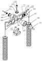
进一步,所述升降机构包括支撑板、托板、伺服驱动器、底座和导向轴;所述底座上部设置有所述支撑板,所述支撑板两端设置有圆孔,用于所述砝码组穿过该支撑板;位于所述支撑板的下方,在所述壳体两侧分别设置有竖向滑轨,所述竖向滑轨上设置有由所述伺服驱动器驱动的滑块,且所述滑块上设置有用于承托所述砝码组的所述托板,所述托板的端部设置有所述导向轴,所述导向轴两端分别与所述底座和支撑板连接。Further, the lifting mechanism includes a support plate, a support plate, a servo driver, a base and a guide shaft; the support plate is arranged on the upper part of the base, and round holes are arranged at both ends of the support plate for the weight set Passing through the support plate; located below the support plate, vertical slide rails are respectively provided on both sides of the housing, the vertical slide rails are provided with sliders driven by the servo driver, and all The sliding block is provided with the supporting plate for supporting the weight group, the end of the supporting plate is provided with the guiding shaft, and the two ends of the guiding shaft are respectively connected with the base and the supporting plate.
进一步,所述底座一端设置有支撑柱,所述支撑柱设置在壳体内。Further, one end of the base is provided with a support column, and the support column is arranged in the housing.
本发明由于采取以上技术方案,其具有以下优点:本发明采用的杠杆两端呈圆弧形结构,中心支撑可采用刀口以及各类轴承(气浮轴承等);采用钢带连接砝码组,保证砝码组力偶矩不变,有效提高了灵敏度,并实现了对各类便携式扭矩计量器具的检测。Due to the adoption of the above technical solutions, the present invention has the following advantages: the two ends of the lever adopted by the present invention are arc-shaped structures, and the center support can use knife edges and various types of bearings (air bearing, etc.); the steel belt is used to connect the weight group, It ensures that the couple moment of the weight group remains unchanged, effectively improves the sensitivity, and realizes the detection of various portable torque measuring instruments.
附图说明Description of drawings
图1是本发明的整体结构示意图;Fig. 1 is the overall structure schematic diagram of the present invention;
图2是本发明实施例杠杆砝码机构分解示意图;Fig. 2 is the exploded schematic diagram of the lever weight mechanism according to the embodiment of the present invention;
图3是本发明实施例水平移动机构分解示意图;3 is an exploded schematic diagram of a horizontal moving mechanism according to an embodiment of the present invention;
图4是本发明实施例升降机构构分解示意图;4 is a schematic exploded view of the structure of the lifting mechanism according to the embodiment of the present invention;
附图标记:1杠杆砝码机构、2水平移动机构、3升降机构、101杠杆、102钢带、103砝码组、104中轴、105中刀架、106中刀、107中刀支座、108调节支架、109中调节螺母、110中锁紧螺母、111中调节螺栓、112上调节螺母、113上调节螺栓、114上锁紧螺母、115侧调节螺栓、116侧调节螺母、117侧锁紧螺母、201减速机支撑座、202减速电机、203水平手轮、204直线导轨、205水平底座、206杠杆组垫块、207手摇升降台、301支撑板、302托板、303伺服驱动器、304底座、305支撑柱、306导向轴。Reference numerals: 1 lever weight mechanism, 2 horizontal movement mechanism, 3 lifting mechanism, 101 lever, 102 steel belt, 103 weight group, 104 central axis, 105 medium knife holder, 106 medium knife, 107 medium knife support, 108 Adjusting bracket, 109 adjusting nut, 110 locking nut, 111 middle adjusting bolt, 112 upper adjusting nut, 113 upper adjusting bolt, 114 upper locking nut, 115 side adjusting bolt, 116 side adjusting nut, 117 side locking Nut, 201 reducer support base, 202 reducer motor, 203 horizontal handwheel, 204 linear guide rail, 205 horizontal base, 206 lever block, 207 hand lift table, 301 support plate, 302 pallet, 303 servo driver, 304 Base, 305 support column, 306 guide shaft.
具体实施方式Detailed ways
在本发明的描述中,需要理解的是,术语“上”、“下”“内”、“外”等指示的方位或位置关系为基于附图所示的方位或位置关系,仅是为了便于描述本发明和简化描述,而不是指示或暗示所指的装置或元件必须具有特定的方位、以特定的方位构造和操作,因此不能理解为对本发明的限制。下面结合附图和实施例对本发明进行详细的描述。In the description of the present invention, it should be understood that the orientation or positional relationship indicated by the terms "upper", "lower", "inner", "outer", etc. is based on the orientation or positional relationship shown in the accompanying drawings, and is only for convenience The invention is described and simplified without indicating or implying that the device or element referred to must have a particular orientation, be constructed and operate in a particular orientation, and therefore should not be construed as limiting the invention. The present invention will be described in detail below with reference to the accompanying drawings and embodiments.
如图1所示,本发明提供一种扭矩基准机,其包括壳体,以及设置在壳体上的杠杆砝码机构1、水平移动机构2和升降机构3。杠杆砝码机构1设置在水平移动机构2上,且杠杆砝码机构1位于壳体一端,用于加载扭矩,水平移动机构2设置在壳体另一端,用于放置连接被测工件,并将被测工件调整为水平放置。升降机构3设置在壳体两侧,位于杠杆砝码机构1的下方,用于升降砝码,给测量加载力矩。其中:As shown in FIG. 1 , the present invention provides a torque reference machine, which includes a casing, a lever-weight mechanism 1 , a horizontal moving mechanism 2 and a lifting mechanism 3 arranged on the casing. The lever-weight mechanism 1 is arranged on the horizontal moving mechanism 2, and the lever-weight mechanism 1 is located at one end of the housing for loading torque, and the horizontal moving mechanism 2 is arranged at the other end of the housing for placing and connecting the workpiece to be tested, and connecting the measured workpiece. The workpiece to be tested is adjusted to be placed horizontally. The lifting mechanism 3 is arranged on both sides of the housing, below the lever-weight mechanism 1, and is used for lifting and lowering the weight to load torque for measurement. in:
如图2所示,杠杆砝码机构1为一杠杆结构,其包括杠杆101、钢带102、砝码组103、中轴104、中刀架105、调节装置、中刀106和中刀支座107。杠杆101两端设置为圆弧形结构,且圆弧中心位于中刀106的刀刃上。砝码组103通过钢带102连接在杠杆101两端,通过钢带102确保砝码组103在摆动时不会改变砝码组103的位置。杠杆101中部设置有安装孔,中刀106的第一端通过调节装置固定在杠杆101一侧,中刀106第二端穿过安装孔后,穿设在中刀架105内,中刀架105安装在杠杆101另一侧;中刀106的第二端端部与中轴104一端连接,且中轴104通过轴承与中刀架105连接,中轴104另一端与被测件一端连接。位于安装孔下方设置有中刀支座107,中刀支座107安装在水平移动机构2上,用于支撑整个杠杆砝码机构1;位于杠杆101两侧的中刀106两端架设在中刀支座107上,与中刀支座107为线接触,以确保摆动时没有外力的干扰。As shown in FIG. 2 , the lever-weight mechanism 1 is a lever structure, which includes a
上述实施例中,调节装置包括水平调节装置和垂直调节装置。水平调节装置设置在杠杆101一侧,并与中刀106的第一端连接;垂直调节装置设置在杠杆101上部,穿过安装孔与中刀106垂直接触。水平调节装置包括调节支架108、中调节螺母109、中锁紧螺母110和中调节螺栓111。调节支架108一端与中刀106的第一端连接,调节支架108另一端依次与中调节螺母109、中锁紧螺母110和中调节螺栓111连接,通过中调节螺母109来调节整个机构的前后水平。垂直调节装置包括上调节螺母112、上调节螺栓113和上锁紧螺母114,上调节螺栓113一端依次穿过上调节螺母112和杠杆101后与中刀106垂直接触,上调节螺栓113另一端与上锁紧螺母114连接。In the above embodiment, the adjustment device includes a horizontal adjustment device and a vertical adjustment device. The horizontal adjustment device is arranged on one side of the
上述各实施例中,杠杆101上还设置有用于调节砝码组103左右水平的侧调节螺栓115、侧调节螺母116和侧锁紧螺母117;侧调节螺栓115穿过侧调节螺母116与杠杆101连接,位于侧调节螺栓115的端部设置有侧锁紧螺母117。In the above embodiments, the
上述各实施例中,杠杆11可以采用镂空结构。In the above embodiments, the lever 11 may adopt a hollow structure.
上述各实施例中,中刀106还可以采用各类轴承替代,例如气浮轴承等。In the above-mentioned embodiments, the
如图3所示,水平移动机构2包括减速机支撑座201、减速电机202、水平手轮203、直线导轨204、水平底座205、杠杆组垫块206和手摇升降台207。水平底座205安装在壳体上,且水平底座205一端设置有杠杆组垫块206,中刀支座107安装在杠杆组垫块206;水平底座205另一端设置有直线导轨204。直线导轨204上滑动设置有减速机支撑座201和手摇升降台207,手摇升降台207位于减速机支撑座201与杠杆组垫块206之间,设置在手摇升降台207前方。减速机支撑座201上部设置有减速电机202,减速电机202的输出轴穿过减速机支撑座201,且该输出轴与被测件另一端连接。位于减速机支撑座201的底部设置有驱动杆,驱动杆端部设置有水平手轮203,通过水平手轮203带动驱动杆动作,进而驱动减速机支撑座201在直线导轨204进行直线运动。As shown in FIG. 3 , the horizontal moving mechanism 2 includes a
其中,手摇升降台207一侧设置有手摇轮,用于驱动手摇升降台207上升或下降,进而通过手摇升降台207调整被测件的高度。使用时,被测件由手摇升降台207承托,两端分别与中轴104和减速电机202的输出轴连接后,手摇升降台207下降撤出。Among them, a hand wheel is provided on one side of the hand lift table 207, which is used to drive the hand lift table 207 to rise or fall, and then adjust the height of the test piece through the hand lift table 207. When in use, the test piece is supported by the hand lift table 207, and the two ends are respectively connected with the
如图4所示,升降机构3包括支撑板301、托板302、伺服驱动器303、底座304、支撑柱305和导向轴306。底座304一端设置有支撑柱305,支撑柱305设置在壳体内,用于支撑壳体并保证壳体的稳固性。底座304另一端上部设置有支撑板301,支撑板301两端设置有圆孔,用于砝码组103穿过该支撑板。位于支撑板301的下方,在壳体两侧分别设置有竖向滑轨,竖向滑轨上设置有由伺服驱动器303驱动的滑块,且滑块上设置有托板302,通过托板302承托砝码组103。托板302的端部设置有导向轴306,导向轴306两端分别与底座304和支撑板301连接。使用时,由伺服驱动器303带动托板302上下移动,进而为砝码组103提供升降的动力,通过该伺服驱动器303可以确保每次升降砝码组103位置的精准和平稳。As shown in FIG. 4 , the lifting mechanism 3 includes a
综上,本发明的扭矩基准机可以保证砝码组103力偶矩不变,以实现对各类便携式扭矩计量器具,如标准扭矩仪、标准扭矩扳子、工作扭矩仪及扭矩扳子的检测;通过杠杆101的设置可实现目前所有便携式扭矩计量器具的检测。使用时,杠杆砝码机构1用来加载扭矩,水平移动机构2用来放置连接被测件;增加手摇升降台207,适用多种尺寸工件,通过升降机构3中的伺服驱动器303来升降砝码组103,给测量加载力矩,砝码组103升降采用伺服单轴驱动器,确保砝码每次升降平稳精确。To sum up, the torque reference machine of the present invention can ensure that the couple moment of the
上述各实施例仅用于说明本发明,各部件的结构、尺寸、设置位置及形状都是可以有所变化的,在本发明技术方案的基础上,凡根据本发明原理对个别部件进行的改进和等同变换,均不应排除在本发明的保护范围之外。The above-mentioned embodiments are only used to illustrate the present invention, and the structure, size, setting position and shape of each component can be changed to some extent. and equivalent transformations shall not be excluded from the protection scope of the present invention.
Claims (10)
Translated fromChinesePriority Applications (1)
| Application Number | Priority Date | Filing Date | Title |
|---|---|---|---|
| CN202010327345.3ACN111323164B (en) | 2020-04-23 | 2020-04-23 | A torque reference machine |
Applications Claiming Priority (1)
| Application Number | Priority Date | Filing Date | Title |
|---|---|---|---|
| CN202010327345.3ACN111323164B (en) | 2020-04-23 | 2020-04-23 | A torque reference machine |
Publications (2)
| Publication Number | Publication Date |
|---|---|
| CN111323164Atrue CN111323164A (en) | 2020-06-23 |
| CN111323164B CN111323164B (en) | 2025-02-25 |
Family
ID=71168197
Family Applications (1)
| Application Number | Title | Priority Date | Filing Date |
|---|---|---|---|
| CN202010327345.3AActiveCN111323164B (en) | 2020-04-23 | 2020-04-23 | A torque reference machine |
Country Status (1)
| Country | Link |
|---|---|
| CN (1) | CN111323164B (en) |
Cited By (2)
| Publication number | Priority date | Publication date | Assignee | Title |
|---|---|---|---|---|
| CN114061829A (en)* | 2021-11-12 | 2022-02-18 | 中国船舶重工集团公司第七0四研究所 | High accuracy moment of torsion calbiration system based on under high low temperature environment |
| CN117030085A (en)* | 2023-09-27 | 2023-11-10 | 苏州市计量测试院 | Lever type large torque tester |
Citations (5)
| Publication number | Priority date | Publication date | Assignee | Title |
|---|---|---|---|---|
| CN103575463A (en)* | 2013-11-08 | 2014-02-12 | 吉林大学 | Independent weight loading-unloading dead-load type torque measurement device |
| CN104165723A (en)* | 2013-05-16 | 2014-11-26 | 中国计量科学研究院 | Full-automatic micro torque standard device |
| CN205262671U (en)* | 2015-12-04 | 2016-05-25 | 陕西东方航空仪表有限责任公司 | Torsion -testing appearance calibrating device |
| CN106197843A (en)* | 2016-08-31 | 2016-12-07 | 北京航天动力研究所 | A kind of on-site torsion calibration device |
| CN211576455U (en)* | 2020-04-23 | 2020-09-25 | 北京特思迪设备制造有限公司 | Torque reference machine |
- 2020
- 2020-04-23CNCN202010327345.3Apatent/CN111323164B/enactiveActive
Patent Citations (5)
| Publication number | Priority date | Publication date | Assignee | Title |
|---|---|---|---|---|
| CN104165723A (en)* | 2013-05-16 | 2014-11-26 | 中国计量科学研究院 | Full-automatic micro torque standard device |
| CN103575463A (en)* | 2013-11-08 | 2014-02-12 | 吉林大学 | Independent weight loading-unloading dead-load type torque measurement device |
| CN205262671U (en)* | 2015-12-04 | 2016-05-25 | 陕西东方航空仪表有限责任公司 | Torsion -testing appearance calibrating device |
| CN106197843A (en)* | 2016-08-31 | 2016-12-07 | 北京航天动力研究所 | A kind of on-site torsion calibration device |
| CN211576455U (en)* | 2020-04-23 | 2020-09-25 | 北京特思迪设备制造有限公司 | Torque reference machine |
Cited By (3)
| Publication number | Priority date | Publication date | Assignee | Title |
|---|---|---|---|---|
| CN114061829A (en)* | 2021-11-12 | 2022-02-18 | 中国船舶重工集团公司第七0四研究所 | High accuracy moment of torsion calbiration system based on under high low temperature environment |
| CN117030085A (en)* | 2023-09-27 | 2023-11-10 | 苏州市计量测试院 | Lever type large torque tester |
| CN117030085B (en)* | 2023-09-27 | 2024-02-06 | 苏州市计量测试院 | A lever type large torque measuring instrument |
Also Published As
| Publication number | Publication date |
|---|---|
| CN111323164B (en) | 2025-02-25 |
Similar Documents
| Publication | Publication Date | Title |
|---|---|---|
| CN103575463B (en) | Independent weight loading-unloading dead-load type torque measurement device | |
| CN109631775B (en) | Height detection equipment for rotor and stator core of compressor | |
| CN101358893B (en) | Automatic Swimming Force Calibration Machine | |
| CN111879512A (en) | Worm gear meshing detection device | |
| CN101581629B (en) | Self-locking test device of automobile cable pulley type glass lifter | |
| CN203858167U (en) | Grinding wheel surface hardness detection device | |
| CN111323164A (en) | Torque reference machine | |
| CN112797941B (en) | Calibrating device for railway platform limit measuring instrument | |
| CN211576455U (en) | Torque reference machine | |
| CN115290025A (en) | A multi-dimensional inspection device for high-speed fan blade products | |
| CN201364223Y (en) | Fully-automatic rider type force calibration machine | |
| CN210862509U (en) | A flatness inspection tool for automobile welded structural parts | |
| CN2653434Y (en) | Adjustable axial part measurer | |
| CN117890106A (en) | Fault detection system of wheel set bearing | |
| CN117405343A (en) | An axial impact load test device during the operation of planetary roller screw | |
| CN214224048U (en) | Railway platform limit measuring instrument calibrating installation | |
| CN211262305U (en) | A multifunctional spindle inspection platform | |
| CN204831260U (en) | A steel ball measuring platform | |
| CN203551194U (en) | Dead weight-type torque-measuring apparatus capable of independently loading and unloading counterweight | |
| CN101246088A (en) | Verification device for the corner disc of portable four-wheel aligner | |
| CN223037243U (en) | An electronic weighing device | |
| CN217127893U (en) | Track inspection tester verification platform | |
| CN221300662U (en) | Length measuring instrument capable of measuring rapidly | |
| CN110779488A (en) | Self-adaptive measuring system for measuring distance of overall dimension parameters of steel and control method | |
| CN222087714U (en) | Speed sensor test bed with regulatory function |
Legal Events
| Date | Code | Title | Description |
|---|---|---|---|
| PB01 | Publication | ||
| PB01 | Publication | ||
| SE01 | Entry into force of request for substantive examination | ||
| SE01 | Entry into force of request for substantive examination | ||
| GR01 | Patent grant | ||
| GR01 | Patent grant |