CN111317595A - A kind of vascular stent for preventing membrane slippage - Google Patents
A kind of vascular stent for preventing membrane slippageDownload PDFInfo
- Publication number
- CN111317595A CN111317595ACN201811546041.5ACN201811546041ACN111317595ACN 111317595 ACN111317595 ACN 111317595ACN 201811546041 ACN201811546041 ACN 201811546041ACN 111317595 ACN111317595 ACN 111317595A
- Authority
- CN
- China
- Prior art keywords
- support frame
- annular support
- suture
- film
- covering
- Prior art date
- Legal status (The legal status is an assumption and is not a legal conclusion. Google has not performed a legal analysis and makes no representation as to the accuracy of the status listed.)
- Granted
Links
- 239000012528membraneSubstances0.000titleclaimsabstractdescription28
- 230000002792vascularEffects0.000titleclaimsabstractdescription25
- 230000002265preventionEffects0.000claimsabstractdescription10
- 210000004204blood vesselAnatomy0.000claimsdescription57
- 229910000831SteelInorganic materials0.000claimsdescription46
- 239000010959steelSubstances0.000claimsdescription46
- 239000011248coating agentSubstances0.000claimsdescription9
- 238000000576coating methodMethods0.000claimsdescription9
- 239000003292glueSubstances0.000claimsdescription5
- 230000002093peripheral effectEffects0.000claimsdescription4
- 230000007423decreaseEffects0.000claimsdescription2
- 238000012800visualizationMethods0.000claims1
- 239000010408filmSubstances0.000description99
- 238000010586diagramMethods0.000description18
- 229910001000nickel titaniumInorganic materials0.000description11
- 238000000034methodMethods0.000description9
- HZEWFHLRYVTOIW-UHFFFAOYSA-N[Ti].[Ni]Chemical compound[Ti].[Ni]HZEWFHLRYVTOIW-UHFFFAOYSA-N0.000description7
- 229910052751metalInorganic materials0.000description7
- 239000002184metalSubstances0.000description7
- 230000017531blood circulationEffects0.000description5
- 230000007704transitionEffects0.000description5
- 239000007769metal materialSubstances0.000description4
- 229920000642polymerPolymers0.000description4
- 208000019553vascular diseaseDiseases0.000description4
- 239000013039cover filmSubstances0.000description3
- 238000002224dissectionMethods0.000description3
- 239000000463materialSubstances0.000description3
- 239000004810polytetrafluoroethyleneSubstances0.000description3
- 229920001343polytetrafluoroethylenePolymers0.000description3
- 230000006835compressionEffects0.000description2
- 238000007906compressionMethods0.000description2
- 201000010099diseaseDiseases0.000description2
- 208000037265diseases, disorders, signs and symptomsDiseases0.000description2
- 230000000694effectsEffects0.000description2
- 238000002513implantationMethods0.000description2
- 238000012986modificationMethods0.000description2
- 230000004048modificationEffects0.000description2
- 238000003825pressingMethods0.000description2
- 229910001285shape-memory alloyInorganic materials0.000description2
- 239000010935stainless steelSubstances0.000description2
- 229910001256stainless steel alloyInorganic materials0.000description2
- 238000001356surgical procedureMethods0.000description2
- 229910052715tantalumInorganic materials0.000description2
- GUVRBAGPIYLISA-UHFFFAOYSA-Ntantalum atomChemical compound[Ta]GUVRBAGPIYLISA-UHFFFAOYSA-N0.000description2
- 238000004804windingMethods0.000description2
- 206010002329AneurysmDiseases0.000description1
- 206010066901Treatment failureDiseases0.000description1
- 206010070693Vascular dissectionDiseases0.000description1
- 230000004323axial lengthEffects0.000description1
- 238000010276constructionMethods0.000description1
- 239000004744fabricSubstances0.000description1
- 238000003384imaging methodMethods0.000description1
- 239000007943implantSubstances0.000description1
- 230000001788irregularEffects0.000description1
- 230000003902lesionEffects0.000description1
- 238000004519manufacturing processMethods0.000description1
- HLXZNVUGXRDIFK-UHFFFAOYSA-Nnickel titaniumChemical compound[Ti].[Ti].[Ti].[Ti].[Ti].[Ti].[Ti].[Ti].[Ti].[Ti].[Ti].[Ni].[Ni].[Ni].[Ni].[Ni].[Ni].[Ni].[Ni].[Ni].[Ni].[Ni].[Ni].[Ni].[Ni]HLXZNVUGXRDIFK-UHFFFAOYSA-N0.000description1
- 229920000728polyesterPolymers0.000description1
- 239000005020polyethylene terephthalateSubstances0.000description1
- 239000002861polymer materialSubstances0.000description1
- 208000037803restenosisDiseases0.000description1
- 238000009958sewingMethods0.000description1
- 238000002560therapeutic procedureMethods0.000description1
- 230000000472traumatic effectEffects0.000description1
- 238000003466weldingMethods0.000description1
Images


Classifications
- A—HUMAN NECESSITIES
- A61—MEDICAL OR VETERINARY SCIENCE; HYGIENE
- A61F—FILTERS IMPLANTABLE INTO BLOOD VESSELS; PROSTHESES; DEVICES PROVIDING PATENCY TO, OR PREVENTING COLLAPSING OF, TUBULAR STRUCTURES OF THE BODY, e.g. STENTS; ORTHOPAEDIC, NURSING OR CONTRACEPTIVE DEVICES; FOMENTATION; TREATMENT OR PROTECTION OF EYES OR EARS; BANDAGES, DRESSINGS OR ABSORBENT PADS; FIRST-AID KITS
- A61F2/00—Filters implantable into blood vessels; Prostheses, i.e. artificial substitutes or replacements for parts of the body; Appliances for connecting them with the body; Devices providing patency to, or preventing collapsing of, tubular structures of the body, e.g. stents
- A61F2/02—Prostheses implantable into the body
- A61F2/04—Hollow or tubular parts of organs, e.g. bladders, tracheae, bronchi or bile ducts
- A61F2/06—Blood vessels
- A61F2/07—Stent-grafts
- A61F2002/075—Stent-grafts the stent being loosely attached to the graft material, e.g. by stitching
Landscapes
- Health & Medical Sciences (AREA)
- Gastroenterology & Hepatology (AREA)
- Pulmonology (AREA)
- Cardiology (AREA)
- Oral & Maxillofacial Surgery (AREA)
- Transplantation (AREA)
- Engineering & Computer Science (AREA)
- Biomedical Technology (AREA)
- Heart & Thoracic Surgery (AREA)
- Vascular Medicine (AREA)
- Life Sciences & Earth Sciences (AREA)
- Animal Behavior & Ethology (AREA)
- General Health & Medical Sciences (AREA)
- Public Health (AREA)
- Veterinary Medicine (AREA)
- Media Introduction/Drainage Providing Device (AREA)
- Prostheses (AREA)
Abstract
Translated fromChinese
Description
Translated fromChinese技术领域technical field
本发明涉及可植入血管技术领域,尤其涉及一种防止覆膜滑脱的血管支架。The present invention relates to the technical field of implantable blood vessels, and in particular, to a blood vessel stent for preventing slippage of membranes.
背景技术Background technique
随着人们生活水平的提高和生活方式的改变,血管疾病发病率越来越高,这些疾病若不及时治疗可能会导致血管堵塞、动脉瘤等疾病,将严重危害人类的生命安全。With the improvement of people's living standards and changes in lifestyle, the incidence of vascular diseases is getting higher and higher. If these diseases are not treated in time, they may lead to diseases such as vascular blockage and aneurysm, which will seriously endanger human life.
目前可以采用微创伤介入术治疗血管疾病,此类方法对病人的创伤小,安全性高,有效性高,因此受到医生与患者的肯定,已成为血管疾病的重要治疗方法。介入性治疗方法是指用输送系统将血管支架植入患者血管病变段,植入的血管支架通过扩张可以支撑狭窄闭塞段血管或封堵血管夹层破口,减少血管弹性回缩及再塑形,保持管腔血流通畅,还具有预防再狭窄的作用。At present, micro-invasive interventional surgery can be used to treat vascular diseases. Such methods are less traumatic to patients, have high safety and high effectiveness, so they are affirmed by doctors and patients and have become an important treatment method for vascular diseases. Interventional therapy refers to the use of a delivery system to implant a vascular stent into a patient's vascular disease segment. The implanted vascular stent can support the narrowed and occluded segment of the blood vessel or block the vascular dissection rupture through expansion, reducing the elastic retraction and reshaping of the blood vessel. Keeping lumen blood flow unobstructed also has the effect of preventing restenosis.
目前常用的血管支架包括覆膜支架和裸金属支架两大类,其中覆膜支架是在裸金属支架上设有覆膜,能够完全隔绝血流和有病变的血管,从而免除血管破裂的致命性风险。现有的很多覆膜支架在端部设置有一段没有缝合在覆膜上的环状支撑架,利用这段裸露在覆膜外部的环状支撑架可以将血管支架固定在输送器上,此类型的血管支架在使用过程中需要通过介入的方式将支架植入人体内,这种方式需将人造的覆膜支架压缩进输送释放装置,沿着事先植入的导丝引导送入人体,在显影系统的协助下,将输送释放装置准确输送到血管的病变位置,然后释放覆膜支架。Currently commonly used vascular stents include covered stents and bare metal stents. Among them, covered stents are covered on bare metal stents, which can completely isolate blood flow and diseased blood vessels, thereby avoiding the fatality of blood vessel rupture. risk. Many existing stent-grafts are provided with a ring-shaped support at the end that is not sutured to the cover. The vascular stent can be fixed on the conveyor by using this ring-shaped support that is exposed outside the cover. This type of stent-graft In the process of use, the stent needs to be implanted into the human body through intervention. In this way, the artificial stent-graft needs to be compressed into the delivery and release device, and guided into the human body along the pre-implanted guide wire. With the assistance of the system, the delivery and release device is accurately delivered to the lesion site of the blood vessel, and then the stent graft is released.
目前市场上这种覆膜支架的结构设计存在一些弊端,如输送器释放覆膜支架的过程中覆膜容易滑脱、覆膜与支架之间连接不牢固等,这些不良的因素会导致覆膜血管支架在血管内不良的展开形态、柔顺性不佳、扩展内径不规则,从而导致覆膜支架与血管贴壁不良,进而导致血流受阻或夹层破口未被封堵,造成治疗失败甚至需进行二次手术治疗。At present, there are some drawbacks in the structural design of this stent-graft on the market, such as easy slippage of the stent during the delivery of the stent-graft by the delivery device, and weak connection between the stent-graft and the stent. The stent has poor deployment shape, poor compliance, and irregular expansion diameter in the blood vessel, resulting in poor adherence between the stent-graft and the blood vessel, which in turn leads to obstruction of blood flow or unblocked dissection rupture, resulting in treatment failure or even the need for further treatment. Secondary surgical treatment.
发明内容SUMMARY OF THE INVENTION
本发明的目的在于提供一种防止覆膜滑脱的血管支架。The object of the present invention is to provide a stent for preventing the slippage of the membrane.
为了解决上述技术问题,本发明提供了一种防止覆膜滑脱的血管支架,其包括覆膜及设置于所述覆膜上的主体支撑架,所述主体支撑架包括部分裸露出所述覆膜的端部环状支撑架,所述血管支架还包括防脱件,所述防脱件设置于所述端部环状支撑架与覆膜之间,所述防脱件用于固定覆膜至血管支架,以防止覆膜滑脱褶皱。In order to solve the above technical problems, the present invention provides a stent for preventing the slippage of the membrane, which includes a membrane and a main body support frame arranged on the membrane, and the main support frame includes a partially exposed membrane. The end annular support frame, the blood vessel stent further includes a detachment prevention piece, the detachment prevention piece is arranged between the end annular support frame and the membrane, and the detachment prevention piece is used to fix the membrane to the Vascular stents to prevent the membrane from slipping folds.
本发明提供的血管支架通过防脱件将覆膜的端部固定于端部环状支撑架上,以防止覆膜滑脱褶皱。因此,所述血管支架在通过输送器的释放过程中,由于覆膜通过防脱件稳定地固定于端部环状支撑架上,能确保覆膜不会滑脱褶皱,以使血管支架在血管内良好的展开形态、柔顺性较佳、扩展内径规则,从而使血管支架与血管贴壁良好,能防止血流受阻或夹层破口未被封堵。In the blood vessel stent provided by the present invention, the end of the covering film is fixed on the annular support frame at the end through the anti-slip member, so as to prevent the covering film from slipping off and wrinkling. Therefore, during the release process of the vascular stent through the delivery device, since the covering film is stably fixed on the end annular support frame through the anti-falling element, it can ensure that the covering film does not slip off and fold, so that the vascular stent can be kept inside the blood vessel. Good deployment shape, good flexibility, and regular expansion inner diameter, so that the vascular stent adheres well to the blood vessel, which can prevent blood flow from being blocked or the dissection rupture from being blocked.
附图说明Description of drawings
为了更清楚地说明本发明实施例的技术方案,下面将对实施方式中所需要使用的附图作简单地介绍,显而易见地,下面描述中的附图是本发明一些实施方式,对于本领域普通技术人员来讲,在不付出创造性劳动的前提下,还可以根据这些附图获得其他的附图。In order to illustrate the technical solutions of the embodiments of the present invention more clearly, the following briefly introduces the accompanying drawings used in the implementation manner. As far as technical personnel are concerned, other drawings can also be obtained based on these drawings without any creative effort.
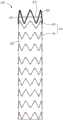
图1是本发明第一实施例提供的血管支架的结构示意图。FIG. 1 is a schematic structural diagram of a blood vessel stent provided by a first embodiment of the present invention.
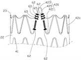
图2是图1中的血管支架的局部放大图。FIG. 2 is a partial enlarged view of the blood vessel stent in FIG. 1 .
图3是图1中的端部环状支撑架的立体结构示意图。FIG. 3 is a schematic three-dimensional structure diagram of the end annular support frame in FIG. 1 .
图4是本发明第二实施例提供的血管支架的结构示意图。FIG. 4 is a schematic structural diagram of a blood vessel stent provided by a second embodiment of the present invention.
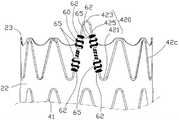
图5是图4中的血管支架的局部放大图。FIG. 5 is a partial enlarged view of the blood vessel stent in FIG. 4 .
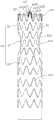
图6是本发明第三实施例提供的血管支架的结构示意图。FIG. 6 is a schematic structural diagram of a blood vessel stent provided by a third embodiment of the present invention.
图7是本发明第四实施例提供的血管支架的结构示意图。FIG. 7 is a schematic structural diagram of a blood vessel stent provided by a fourth embodiment of the present invention.
图8是图7中的血管支架的局部放大图。FIG. 8 is a partial enlarged view of the blood vessel stent in FIG. 7 .
图9是本发明第五实施例提供的血管支架的结构示意图。FIG. 9 is a schematic structural diagram of a blood vessel stent provided by a fifth embodiment of the present invention.
图10是图9中的血管支架的局部放大图。FIG. 10 is a partial enlarged view of the blood vessel stent in FIG. 9 .
图11是本发明第六实施例提供的血管支架的结构示意图。FIG. 11 is a schematic structural diagram of a blood vessel stent provided by a sixth embodiment of the present invention.
图12是本发明第七实施例提供的血管支架的结构示意图。FIG. 12 is a schematic structural diagram of a blood vessel stent provided by a seventh embodiment of the present invention.
图13是本发明第八实施例提供的血管支架的结构示意图。FIG. 13 is a schematic structural diagram of a blood vessel stent provided by an eighth embodiment of the present invention.
具体实施方式Detailed ways
下面将结合本发明实施例中的附图,对本发明实施例中的技术方案进行清楚、完整地描述,显然,所描述的实施例仅仅是本发明一部分实施例,而不是全部的实施例。基于本发明中的实施例,本领域普通技术人员在没有付出创造性劳动前提下所获得的所有其他实施例,都属于本发明保护的范围。The technical solutions in the embodiments of the present invention will be clearly and completely described below with reference to the accompanying drawings in the embodiments of the present invention. Obviously, the described embodiments are only a part of the embodiments of the present invention, but not all of the embodiments. Based on the embodiments of the present invention, all other embodiments obtained by those of ordinary skill in the art without creative efforts shall fall within the protection scope of the present invention.
此外,以下各实施例的说明是参考附加的图示,用以例示本发明可用以实施的特定实施例。本发明中所提到的方向用语,例如,“上”、“下”、“前”、“后”、“左”、“右”、“内”、“外”、“侧面”等,仅是参考附加图式的方向,因此,使用的方向用语是为了更好、更清楚地说明及理解本发明,而不是指示或暗指所指的装置或元件必须具有特定的方位、以特定的方位构造和操作,因此不能理解为对本发明的限制。Furthermore, the following descriptions of the various embodiments refer to the accompanying drawings to illustrate specific embodiments in which the invention may be practiced. Directional terms mentioned in the present invention, such as "up", "down", "front", "rear", "left", "right", "inside", "outside", "side", etc., only Reference is made to the directions of the accompanying drawings, therefore, the directional terms used are for better and clearer description and understanding of the present invention, rather than indicating or implying that the device or element referred to must have a specific orientation, in a specific orientation construction and operation, and therefore should not be construed as limiting the invention.
在本发明的描述中,本发明所述“近端”是指靠近心脏位置的一端,所述“远端”为远离心脏位置的一端。本发明中所述的高、低是相对于覆膜而言,超出覆膜的端面称为高,未超出覆膜端面的称为低,该定义只是为了表述方便,并不能理解为对本发明的限制。In the description of the present invention, the "proximal end" of the present invention refers to the end close to the position of the heart, and the "distal end" refers to the end away from the position of the heart. The high and low mentioned in the present invention are relative to the film. The end face that exceeds the film is called high, and the end face that does not exceed the end face of the film is called low. This definition is only for the convenience of expression, and should not be understood as a limit.
请参阅图1及图2,图1是本发明第一实施例提供的血管支架的结构示意图;图2是图1中的血管支架的局部放大图。本发明提供一种防止覆膜滑脱的血管支架100,其包括管状的覆膜20、设置于所述覆膜20上的一主体支撑架40,以及一防脱件。所述主体支撑架40包括若干个Z形或正弦波形的环状波形支撑杆41,以及部分裸露出所述覆膜20的端面的一端部环状支撑架42,若干环状波形支撑杆41沿所述覆膜20的轴向间隔排布;所述防脱件设置于所述端部环状支撑架42与覆膜20之间,所述防脱件用于固定血管支架100的端部的覆膜20,以防止覆膜20滑脱褶皱。Please refer to FIG. 1 and FIG. 2 , FIG. 1 is a schematic structural diagram of the blood vessel stent provided by the first embodiment of the present invention; FIG. 2 is a partial enlarged view of the blood vessel stent in FIG. 1 . The present invention provides a
本实施例中,所述端部环状支撑架42设置于所述覆膜20的近端,所述覆膜20的近端具有一近端面23,所述端部环状支撑架42的近端裸露出所述覆膜20的近端面23,即端部环状支撑架42的近端高出所述近端面23,所述端部环状支撑架42的近端的远端低于所述近端面23。所述端部环状支撑架42的远端通过防脱件连接于所述覆膜20上,从而使覆膜20的近端固定于所述端部环状支撑架42上。In this embodiment, the end
本发明提供的血管支架100通过防脱件将覆膜20的端部固定于端部环状支撑架42上,以防止覆膜20滑脱褶皱。因此,所述血管支架100在通过输送器的释放过程中,由于覆膜20通过防脱件稳定地固定于端部环状支撑架42上,能确保覆膜20不会滑脱褶皱,以使血管支架100在血管内展开形态良好、柔顺性较佳、扩展内径规则,从而使血管支架100与血管贴壁良好,能防止血流受阻或夹层破口未被封堵。In the
所述覆膜20的横端面的形状是与血管配合的圆形或椭圆形,所述覆膜20采用涤纶布、PTFE、PET或者其他高分子材料制成。这些环状波形支撑杆41缝合或贴接在覆膜20上,且这些环状波形支撑杆41沿所述覆膜20的轴向间隔排布。每一环状波形支撑杆41可以是等波支撑杆或高低波支撑杆等,所述等波支撑杆是指环状波形支撑杆41上的各个波峰的高度相同,且各个波谷的高度也相同,即,各个波峰及各个波谷分别在同一平面上;所述高低波支撑杆是指环状波形支撑杆41上的各个波峰的高度不相同,各个波谷的高度也可以不相同。The shape of the transverse end surface of the covering
每一个环状波形支撑杆41是具有弹性的金属材料制成,所述金属材料包括不锈钢或者记忆合金。本实施例中,每一环状波形支撑杆41通过一条超弹性镍钛丝编织而成,所述超弹性镍钛合金丝可选择的丝径(即直径)范围为0.2mm~0.6mm。每一个环状波形支撑杆41上设置有一连接套,所述连接套将所述环状波形支撑杆41相对的两端连接。Each annular
每一环状波形支撑杆41可以通过缝线缝合在覆膜20上,即,所述缝线可以沿着每一环状波形支撑杆41的波形走向而伴随整个主体支撑架40。所述缝线优选高分子缝合线,所述高分子缝合线可以是PTFE或者PET缝合线。所述缝线也可以通过若干非等间距分布的缝合小结将每一环状波形支撑杆41缝合在覆膜20上。所述缝线的直径选择范围为0.05mm-0.25mm。Each annular
本实施例中,每一环状波形支撑杆41为等波支撑杆,所述环状波形支撑杆41采用0.5mm直径的镍钛丝编织而成,正弦波数量可以是任意数量,环状波形支撑杆41的垂直高度可以是任意高度。In this embodiment, each annular
在其他实施例中,所述环状波形支撑杆41也高低波支撑杆。In other embodiments, the annular
在其他实施例中,每一环状波形支撑杆41也可以通过医用胶水贴合于覆膜20上。In other embodiments, each annular
如图3所示,图3是图1中的端部环状支撑架的立体结构示意图。所述端部环状支撑架42可以是等波支撑杆或高低波支撑杆等,所述端部环状支撑架42的每一Z形或正弦波形均包括一波峰423、一波谷421及连接于所述波峰423与所述波谷421之间的一连接杆425。所述端部环状支撑架42由具有弹性的金属材料制成,所述金属材料包括不锈钢或者记忆合金。优选的,所述端部环状支撑架42通过一条超弹性镍钛丝编织而成,超弹性镍钛合金丝可选择的丝径范围为0.2mm~0.5mm。所述端部环状支撑架42上设置有一连接套427,所述连接套427将所述端部环状支撑架42相对的两端连接,即,所述端部环状支撑架42相对的两端均收纳于所述连接套427内,然后再通过机械压紧或者焊接方式将镍钛丝的两个端固定在连接套427的内部。As shown in FIG. 3 , FIG. 3 is a schematic three-dimensional structure diagram of the end annular support frame in FIG. 1 . The end
本实施例中,所述端部环状支撑架42为等波支撑杆,所述端部环状支撑架42采用0.4mm直径的镍钛丝编织而成。所述防脱件为缝合于所述端部环状支撑架42与覆膜20的缝合线60,所述缝合线60能使覆膜20稳定地固定于所述端部环状支撑架60上。所述缝合线60优选高分子缝合线,所述高分子缝合线可以是PTFE或者PET缝合线。所述缝合线60螺旋缠绕在端部环状支撑架42上并缝合覆膜20,以限制覆膜20轴向移动。In this embodiment, the end
至少在所述端部环状支撑架42与覆膜20的近端面23的相交处螺旋缠绕有所述缝合线60,即,连接杆425与覆膜20的近端面23的相交处螺旋缠绕有所述缝合线60。具体的,所述缝合线60沿所述端部环状支撑架42为路径螺旋缠绕并缝合沿途的覆膜20。所述端部环状支撑架42高出所述覆膜20的近端面23的部分杆体或全部杆体上缝合有所述缝合线60;所述端部环状支撑架42低于所述覆膜20的近端面23的部分杆体或全部杆体上缝合有所述缝合线60。The
本实施例中,所述端部环状支撑架42的全部杆体上螺旋缠绕有所述缝合线60,具体的,所述缝合线60以所述端部环状支撑架42为路径螺旋缠绕一周,所述缝合线60将缝合路径上的覆膜20与端部环状支撑架42缝合,且所述缝合线60的首尾两端通过打结得到一绳结62连接。所述绳结62能将所述缝合线60拉紧,从而使缝合线60紧绷于端部环状支撑架42上;所述缝合线60连接于覆膜20与端部环状支撑架42之间,能使覆膜20紧绷在端部环状支撑架42上,以有效避免在血管支架100释放的过程中覆膜20的近端部相对于端部环状支撑架42滑动或起褶皱。In this embodiment, the
在其他实施例中,端部环状支撑架42的每一波谷421上螺旋缠绕有一根缝合线60,具体的,缝合线60的一端在通过打结得到绳结的方式固定于与所述波谷421连接的其中一连接杆425上,所述缝合线的另一端以所述波谷为路径螺旋缠绕至与所述波谷连接的另一连接杆425上,并通过打结固定。所述缝合线60将缝合路径上的覆膜20与端部环状支撑架42缝合,与所述波谷421连接的两个连接杆425上的绳结均高出所述覆膜20的近端面23。In other embodiments, each
在其他实施例中,端部环状支撑架42的每一连接杆425上螺旋缠绕有一根缝合线60,具体的,所述缝合线60的一端在通过打结得到绳结的方式固定于连接杆425高出所述覆膜20的近端面23的一端,所述缝合线60的另一端以所述连接杆425为路径螺旋缠绕至连接杆425低于覆膜20的近端面23的一端,并通过打结得到绳结的方式固定。所述缝合线60将缝合路径上的覆膜20与端部环状支撑架42缝合。In other embodiments, each connecting
如图2所示,覆膜20的近端和/或远端设置有显影件70,显影件70的显影材料制成。显影件70可以是沿所述覆膜20的近端和/或远端的开口边缘连续或间断排列的多个显影点,这些显影点可通过缝合、冲压、镶设或贴设的方式固定在覆膜20上;由于显影件70具有显影性且为环状,在手术过程中通过影像设备能清楚地观察出显影件70的位置,方便血管支架100的植入。As shown in FIG. 2 , a developing
在其他实施例中,显影件50也可以是连续或间断缠绕于所述覆膜20的近端和/或远端边缘上的显影丝,所述显影丝可以采用由含钽的镍钛合金金属丝。In other embodiments, the developing member 50 may also be a developing wire continuously or intermittently wound on the proximal and/or distal edge of the
在其他实施例中,端部环状支撑架42上螺旋缠绕的缝合线60可以用含显影材料的显影丝取代,所述显影丝优选采用由含钽的镍钛合金金属丝。In other embodiments, the helically wound
在其他实施例中,所述覆膜20的外周壁上开设有开口,所述开口向主体支撑架40的腔内延伸设置有内嵌分支。In other embodiments, the outer peripheral wall of the
请一并参阅图4及图5,图4是本发明第二实施例提供的血管支架的结构示意图;图5是图4中的血管支架的局部放大图。本发明的第二实施例提供的血管支架的结构与第一实施例的结构相似,不同之处在于:在第二实施例中,端部环状支撑架42a上还设置有若干定位件422,缝合线60沿所述端部环状支撑架42a螺旋缠绕并缝合覆膜20,所述缝合线60固定于这些定位件422上,定位件422能防止缝合线60在端部环状支撑架42a上滑动。Please refer to FIG. 4 and FIG. 5 together. FIG. 4 is a schematic structural diagram of a blood vessel stent provided by a second embodiment of the present invention; FIG. 5 is a partial enlarged view of the blood vessel stent in FIG. 4 . The structure of the blood vessel stent provided by the second embodiment of the present invention is similar to that of the first embodiment, except that in the second embodiment, a plurality of
具体的,端部环状支撑架42a通过弹性金属,优选具有超弹性镍钛金属切割加工而成。所述端部环状支撑架42a的结构与第一实施例中的端部环状支撑架42的结构相似,即端部环状支撑架42a可以是等波支撑杆或高低波支撑杆等。所述端部环状支撑架42a的每一Z形或正弦波形均包括一波谷421、一波峰423及连接于所述波峰423与所述波谷421之间的一连接杆425。每一波谷421上开设有一连接孔4212,缝线沿所述连接孔4212的四周缠绕将所述波谷421缝合于覆膜20上。Specifically, the
定位件422的位置高于所述端部环状支撑架42a的近端面23,具体的,定位件422是设置于所述端部环状支撑架422的连接杆425上的凸缘,所述缝合线60沿端部环状支撑架42a螺旋缠绕延伸过凸缘后固定凸缘上。具体的,凸缘设置于连接杆425高于覆膜20的近端面的一端,即连接杆425高于覆膜20的端面的位置有局部凸出,从而形成所述凸缘,所述凸缘的外径大于连接杆425的外径。The position of the
本实施例中,所述端部环状支撑架42a的每一连接杆425高出覆膜20的近端面23的位置凸设有所述凸缘,这些凸缘在端部环状支撑架42a的轴向上平行,即这些凸缘位于同一平面上。每一波谷421与对应的两个连接杆425之间螺旋缠绕有一根缝合线60,即,所述缝合线60的一端在其中一连接杆425的凸缘远离覆膜20的端部通过打结得到绳结62,由于凸缘的外径较大,因此,绳结62无法沿凸缘的外周面朝覆膜20滑动,从而固定了绳结62的高度,使缝合线60的一端被绳结62固定于对应的凸缘的上端;再将所述缝合线60的另一端沿所述其中一连接杆425朝波谷421螺旋缠绕,经所述波谷421及对应的另一连接杆425,并在所述另一连接杆425的凸缘背朝覆膜20的端部,拉紧缝合线后打结得到另一绳结62。所述缝合线60在沿端部环状支撑架42a螺旋缠绕的同时把沿途的覆膜20紧密缝合于端部环状支撑架42a上,以便固定覆膜20于端部环状支撑架42a上。In this embodiment, each connecting
由于缝合线60在端部环状支撑架42a上螺旋缠绕的过程中被拉紧,其拉应力可作用于覆膜20,从而能稳定地固定覆膜20的位置,且由于每一缝合线60两端的绳结62被对应的凸缘阻挡无法沿连接杆425朝覆膜20滑动,使缝合线整体均不会沿端部环状支撑架42a下滑,从而保持缝合线60的拉应力,可有效避免在血管支架100a在释放过程中覆膜20的端面相对于端部环状支撑架42a滑动或起褶皱。Since the
本实施例中,所述主体支撑架40上还设置有分支血管支架44,分支血管支架44的直径小于主体支撑架40的直径。所述分支血管支架44设置于主体支撑架40的远端,所述分支血管支架44包括管状的分支覆膜442及设置于所述分支覆膜442上的若干个Z形或正弦波形的环状波形支撑杆444,这些环状波形支撑杆444沿所述分支血管支架44的轴向间隔排列,每一所述环状波形支撑杆444通过缝线缝合于所述分支覆膜442上。分支覆膜442及环状波形支撑杆444的结构分别与第一实施例中的覆膜20及环状波形支撑杆41相似,仅大小不同,在此不再赘述。本实施例中,所述主体支撑架40的远端设置有两根分支血管支架44。In this embodiment, the main
在其他实施例中,每一连接杆425在对应的波谷421与定位件422之间设置有一根缝合线60,具体的,所述缝合线60的一端在所述连接杆425的凸缘远离覆膜20的端部通过打结得到绳结62,由于凸缘422的外径较大,因此,绳结无法沿凸缘422的外周面朝覆膜20滑动,从而固定了绳结62的高度,使缝合线60的一端被绳结62固定于对应的凸缘422的上方;再将所述缝合线60的另一端沿所述连接杆425朝波谷421螺旋缠绕,在邻近所述波谷421时拉紧缝合线,并在连接孔4212的外周壁上打结得到绳结,所述缝合线60在沿端连接杆425螺旋缠绕的同时把沿途的覆膜20紧密缝合于连接杆425上。In other embodiments, each connecting
请参阅图6,图6是本发明第三实施例提供的血管支架的结构示意图。本发明的第三实施例提供的血管支架的结构与第二实施例的结构相似,不同之处在于:在第三实施例中,端部环状支撑架42b上相邻的两个连接杆425上的定位件422在端部环状支撑架42a的轴向上位置交错。具体的,所述端部环状支撑架42b的每一Z形或正弦波形的两个连接杆425上的定位件422在端部环状支撑架42b的轴向上位置交错,即其中一个定位件422邻近覆膜20,另一个定位件422远离覆膜20。本实施例中的每一Z形或正弦波形的两个连接杆425上的定位件422在端部环状支撑架42b的轴向上位置交错,能减小了端部环状支撑架42b压缩后的最大径向截面积,从而可使端部环状支撑架42b能适用于更小的鞘管,且更易装入输送器。Please refer to FIG. 6 , which is a schematic structural diagram of a blood vessel stent provided by a third embodiment of the present invention. The structure of the blood vessel stent provided by the third embodiment of the present invention is similar to the structure of the second embodiment, the difference is: in the third embodiment, the two adjacent connecting
请一并参阅图7及图8,图7是本发明第四实施例提供的血管支架的结构示意图;图8是图7中的血管支架的局部放大图。本发明的第四实施例提供的血管支架的结构与第一实施例的结构相似,不同之处在于:在第四实施例中,端部环状支撑架42c上还设置有若干定位件,定位件为设置于端部环状支撑架42c的若干钢套65,所述缝合线60沿所述端部环状支撑架42c螺旋缠绕延伸并缝合覆膜20,所述缝合线60固定于钢套65上。端部环状支撑架42c为Z形或正弦波形的高低波支撑杆,钢套65设置于所述高低波支撑杆的高波420上。所述高波420是指其波峰高出所述端部环状支撑架42c的其他波峰。所述钢套65通过压紧等方式卡接于所述端部环状支撑架42c的高波420上,或者所述钢套65与端部环状支撑架42c一体成型制成。每一钢套65的外径大于端部环状支撑架42c的丝杆的丝径。Please refer to FIG. 7 and FIG. 8 together. FIG. 7 is a schematic structural diagram of a blood vessel stent provided by a fourth embodiment of the present invention; FIG. 8 is a partial enlarged view of the blood vessel stent in FIG. 7 . The structure of the blood vessel stent provided by the fourth embodiment of the present invention is similar to the structure of the first embodiment, the difference is: The components are a plurality of
具体的,端部环状支撑架42c通过弹性金属丝,优选具有超弹性的镍钛丝编织而成。端部环状支撑架42c中至少有两个波峰高出其他波峰的高波420,至少两个所述高波420沿所述端部环状支撑架42c的周向均匀间隔设置,即至少两个所述高波420沿所述端部环状支撑架42c的轴心线旋转阵列。每一高波420包括波峰423、两个波谷421及分别连接于所述波峰423与两个所述波谷421之间的两根连接杆425。端部环状支撑架42c可以通过缝线连接于覆膜20上。Specifically, the end
本实施例中,所述端部环状支撑架42c包括三个高波420,三个所述高波420沿所述端部环状支撑架42c的周向均匀间隔排列。每一高波420的两个连接杆425上分别间隔的设置有一对所述钢套65,所述一对钢套65分别设置于所述端部环状支撑架42c与覆膜20的交界的上下两侧,即其中一个钢套65的位置高于所述覆膜20的近端面23、另一个钢套65的位置低于所述覆膜20的近端面23。每一高波420上的两对钢套65在部环状支撑架42c的轴向上平行,即高出近端面23的钢套65在所述部环状支撑架42c的轴向上位于同一平面上,低于近端面23的钢套65在所述部环状支撑架42c的轴向上位于同一平面上。缝合线60沿端部环状支撑架42c的每一高波420的连接杆425的路径螺旋缠绕并缝合沿途覆膜20,缝合线60通过打结的方式固定于所述一对钢套65之间。In this embodiment, the end
具体的,所述缝合线60的一端在每一高波420的其中一连接杆425的高出覆膜20的近端面23的钢套65远离覆膜20的端部通过打结得到绳结62,由于钢套65的外径较大,绳结62无法沿钢套65的外周面朝覆膜20滑动,从而固定了绳结62的高度,使缝合线60的一端被绳结62固定于对应的钢套65的上端;再将所述缝合线60的另一端沿所述其中一连接杆425朝波谷421螺旋缠绕,经另一钢套65并在所述另一钢套65背朝波峰423的端部拉紧缝合线60后打结得到另一绳结62。所述缝合线60在沿端部环状支撑架42c螺旋缠绕的同时把沿途的覆膜20紧密缝合于端部环状支撑架42c上,以便固定覆膜20于端部环状支撑架42c上。由于缝合线60被拉紧,其拉应力可作用于覆膜20,从而能固定覆膜20的位置,又因两个绳结62分别被两个钢套65阻挡无法沿连接杆425滑动,从而固定了缝合线60的两端,使缝合线60整体均不会沿端部环状支撑架42c滑动,能保持缝合线60的拉应力。Specifically, one end of the
本实施例中,覆膜20包括直管段22与锥形段24,所述锥形段24轴向设置于所述直管段22的远端。直管段22的近端设置有所述端部环状支撑架42c,所述端部环状支撑架42c的高波420高出所述覆膜20的近端面23;所述直管段22上设置有若干个Z形或正弦波形的环状波形支撑杆41,若干环状波形支撑杆41沿所述覆膜20的轴向间隔排布。所述锥形段24的直径自近端至远端递减,所述锥形段24上设置有若干个Z形或正弦波形的环状波形支撑杆45,这些环状波形支撑杆45的直径自所述锥形段24的近端与远端递减,环状波形支撑杆45为高低波支撑杆。In this embodiment, the
在其他实施例中,端部环状支撑架42c设置有三个以上的高波420,这些高波420可以沿端部环状支撑架42c的轴心线旋转阵列,每一高波420的两个连接杆425上分别间隔的设置有一对所述钢套65,每一钢套65可以由显影材料制成,以方便血管支架100的植入。In other embodiments, the end
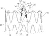
请一并参阅图9及图10,图9是本发明第五实施例提供的血管支架的结构示意图;图10是图9中的血管支架的局部放大图。本发明的第五实施例提供的血管支架的结构与第四实施例的结构相似,不同之处在于:在第五实施例中,端部环状支撑架42c上的每一高波420的两个连接杆425上的两对钢套65在所述端部环状支撑架42c的轴向上位置交错,即其中一对钢套65中的其中之一位于另一对钢套65之间。本实施例中的每一高波420的两个连接杆425上的两对钢套65在所述端部环状支撑架42c的轴向上位置交错,能减小了端部环状支撑架42c压缩后的最大径向截面积,从而可使端部环状支撑架42c能适用于更小的鞘管,且更易装入输送器。Please refer to FIG. 9 and FIG. 10 together. FIG. 9 is a schematic structural diagram of a blood vessel stent provided by a fifth embodiment of the present invention; FIG. 10 is a partial enlarged view of the blood vessel stent in FIG. 9 . The structure of the blood vessel stent provided by the fifth embodiment of the present invention is similar to the structure of the fourth embodiment, the difference is: in the fifth embodiment, two of each
本实施例中,覆膜20为变径圆台形结构,其包括近端直管段25、远端直管段26及连接于近端直管段25与远端直管段26之间的过渡段27,所述过渡段27轴向长度为5-50mm。所述近端直管段25的近端设置有所述端部环状支撑架42c,所述端部环状支撑架42c的高波420高出所述覆膜20的近端面23。所述覆膜20位于过渡段27位置的直径较位于近端直管段25及远端直管段26的直径少。位于近端直管段25处的覆膜20上设置有若干个Z形或正弦波形的环状波形支撑杆41,若干环状波形支撑杆41沿所述覆膜20的轴向间隔排布,每一环状波形支撑杆41为等波支撑杆。位于远端直管段26处的覆膜20上设置有若干个Z形或正弦波形的环状波形支撑杆412,若干环状波形支撑杆412沿所述覆膜20的轴向间隔排布,每一环状波形支撑杆412为高低波支撑杆。位于过渡段27处的覆膜20上设置有位于中部的Z形或正弦波形的环状波形支撑杆414,以及分别位于过渡段27的近端及远端的两个锥状波形支撑杆416,所述环状波形支撑杆414的直径少于环状波形支撑杆41、412的直径。In this embodiment, the covering
请参阅图11,图11是本发明第六实施例提供的血管支架的结构示意图。本发明的第六实施例提供的血管支架的结构与第四实施例的结构相似,不同之处在于:在第六实施例中,端部环状支撑架42c上的每一高波420的两个连接杆425分别设置有一个钢套65,即每一连接杆425高出覆膜20的近端面23的位置设置有一个钢套65,低于覆膜20的近端面23位置的钢套省略。Please refer to FIG. 11 , which is a schematic structural diagram of a blood vessel stent provided by a sixth embodiment of the present invention. The structure of the blood vessel stent provided by the sixth embodiment of the present invention is similar to that of the fourth embodiment, the difference is: in the sixth embodiment, two of each
本实施例中,缝合线60的一端在每一高波420的其中一连接杆425的钢套65远离覆膜20的端部通过打结得到绳结62,由于钢套65的外径较大,绳结62无法沿钢套65的外周面朝覆膜20滑动,从而固定了绳结62的高度,使缝合线60的一端被绳结62固定于对应的钢套65的上端;再将所述缝合线60的另一端沿所述其中一连接杆425朝波谷421螺旋缠绕,至邻近对应的波谷421时,拉紧缝合线60后打结得到另一绳结62。所述缝合线60在沿端部环状支撑架42c的连接杆425螺旋缠绕的同时把沿途的覆膜20紧密缝合于端部环状支撑架42c上,以便固定覆膜20于端部环状支撑架42c上。由于缝合线60被拉紧,其拉应力可作用于覆膜20,从而能固定覆膜20的位置,又因绳结62一端的固定于钢套65上,另一端固定于覆膜20上使绳结62无法沿连接杆425滑动,使缝合线60整体均不会沿端部环状支撑架42c滑动,能保持缝合线60的拉应力。In this embodiment, one end of the
本实施例中,每一高波420的每一连接杆425上省略了一个钢套65,在定位覆膜20的效果相同的基础上,节省了血管支架的制造成本。In this embodiment, a
同一高波420的两个连接杆425上的钢套65在端部环状支撑架42c的轴向上位置可以平行或交错。当同一高波420上的两个钢套65在端部环状支撑架42c的轴向上位置交错时,能减小了端部环状支撑架42c压缩后的最大径向截面积,从而可使端部环状支撑架42c能适用于更小的鞘管,且更易装入输送器。The positions of the
请参阅图12,图12是本发明第七实施例提供的血管支架的结构示意图。本发明的第七实施例提供的血管支架的结构与第一实施例的结构相似,不同之处在于:在第七实施例中,防脱件为设置于端部环状支撑架42与覆膜20之间的医用胶水66,以使所述覆膜20能固定于端部环状支撑架42上。具体的,端部环状支撑架42低于近端面23的连接杆425与覆膜20之间通过医用胶水66贴接固定。本实施例中的,端部环状支撑架42通过医用胶水66贴接于覆膜20上,以防止覆膜20滑脱褶皱。Please refer to FIG. 12. FIG. 12 is a schematic structural diagram of a blood vessel stent provided by a seventh embodiment of the present invention. The structure of the blood vessel stent provided by the seventh embodiment of the present invention is similar to the structure of the first embodiment, the difference is: in the seventh embodiment, the anti-dropping member is provided on the end of the
请参阅图13,图13是本发明第八实施例提供的血管支架的结构示意图。本发明的第八实施例提供的血管支架的结构与第一实施例的结构相似,不同之处在于:在第八实施例中,端部环状支撑架42上还设置有若干定位件,定位件为设置于端部环状支撑架42上的锁固槽428,所述锁固槽428的位置高出所述覆膜20的近端面。缝合线60沿端部环状支撑架42的路径螺旋缠绕并缝合沿途覆膜20,缝合线60的端部固定于锁固槽428内。Please refer to FIG. 13 , which is a schematic structural diagram of a blood vessel stent provided by an eighth embodiment of the present invention. The structure of the blood vessel stent provided by the eighth embodiment of the present invention is similar to the structure of the first embodiment, the difference is: The component is a locking
具体的,端部环状支撑架42的高出近端面23的连接杆425上开设有定线槽428,所述缝合线60的一端在其中一连接杆425的定线槽428内通过打结得到绳结而固定,由于缝合线60的一端连接固于定线槽428内,因此,绳结不易脱离出定线槽428,从而固定了缝合线60的一端的绳结的高度,使缝合线60的一端被绳结固定于对应的定线槽428内;再将所述缝合线60的另一端沿所述连接杆425朝对应的波谷421螺旋缠绕,经过波谷421延伸至另一连接杆425,在邻近所述另一连接杆425上的定线槽428时拉紧缝合线,并在所述另一连接杆425上的定线槽428内打结得到绳结,所述缝合线60在沿端连接杆425螺旋缠绕的同时把沿途的覆膜20紧密缝合于连接杆425上。Specifically, the connecting
以上是本发明实施例的实施方式,应当指出,对于本技术领域的普通技术人员来说,在不脱离本发明实施例原理的前提下,还可以做出若干改进和润饰,这些改进和润饰也视为本发明的保护范围。The above are the implementations of the embodiments of the present invention. It should be pointed out that for those of ordinary skill in the art, without departing from the principles of the embodiments of the present invention, several improvements and modifications can also be made. These improvements and modifications are also It is regarded as the protection scope of the present invention.
Claims (19)
Translated fromChinesePriority Applications (1)
| Application Number | Priority Date | Filing Date | Title |
|---|---|---|---|
| CN201811546041.5ACN111317595B (en) | 2018-12-17 | 2018-12-17 | A vascular stent for preventing the covering from slipping off |
Applications Claiming Priority (1)
| Application Number | Priority Date | Filing Date | Title |
|---|---|---|---|
| CN201811546041.5ACN111317595B (en) | 2018-12-17 | 2018-12-17 | A vascular stent for preventing the covering from slipping off |
Publications (2)
| Publication Number | Publication Date |
|---|---|
| CN111317595Atrue CN111317595A (en) | 2020-06-23 |
| CN111317595B CN111317595B (en) | 2025-04-25 |
Family
ID=71163118
Family Applications (1)
| Application Number | Title | Priority Date | Filing Date |
|---|---|---|---|
| CN201811546041.5AActiveCN111317595B (en) | 2018-12-17 | 2018-12-17 | A vascular stent for preventing the covering from slipping off |
Country Status (1)
| Country | Link |
|---|---|
| CN (1) | CN111317595B (en) |
Cited By (4)
| Publication number | Priority date | Publication date | Assignee | Title |
|---|---|---|---|---|
| CN112891020A (en)* | 2020-12-31 | 2021-06-04 | 深圳市先健畅通医疗有限公司 | Lumen device, conveyor and covered stent |
| WO2023125387A1 (en)* | 2021-12-31 | 2023-07-06 | 先健科技(深圳)有限公司 | Covered stent |
| WO2023124999A1 (en)* | 2021-12-31 | 2023-07-06 | 杭州唯强医疗科技有限公司 | Covered stent, and knotting mode for covered stent |
| WO2025113103A1 (en)* | 2023-11-30 | 2025-06-05 | 先健科技(深圳)有限公司 | Covered stent and delivery system |
Citations (7)
| Publication number | Priority date | Publication date | Assignee | Title |
|---|---|---|---|---|
| US20090163951A1 (en)* | 2007-12-19 | 2009-06-25 | Sara Simmons | Medical devices including sutures with filaments comprising naturally derived collagenous material |
| CN101912319A (en)* | 2010-08-27 | 2010-12-15 | 微创医疗器械(上海)有限公司 | Film coating bracket |
| US20110295363A1 (en)* | 2010-05-25 | 2011-12-01 | Girard Michael J | Prosthetic Heart Valve And Transcatheter Delivered Endoprosthesis Comprising A Prosthetic Heart Valve And A Stent |
| CN103476359A (en)* | 2011-04-19 | 2013-12-25 | 美敦力瓦斯科尔勒公司 | Mobile external coupling for branch vessel connection |
| CN104394799A (en)* | 2012-04-26 | 2015-03-04 | 美敦力瓦斯科尔勒公司 | Stoppers to prevent graft material slippage in a closed web stent-graft |
| US20170128189A1 (en)* | 2014-06-27 | 2017-05-11 | Lifetech Scientific (Shenzhen) Co., Ltd. | Fork-Type Covered Stent |
| CN209916296U (en)* | 2018-12-17 | 2020-01-10 | 杭州唯强医疗科技有限公司 | Prevent vascular support of tectorial membrane slippage |
- 2018
- 2018-12-17CNCN201811546041.5Apatent/CN111317595B/enactiveActive
Patent Citations (7)
| Publication number | Priority date | Publication date | Assignee | Title |
|---|---|---|---|---|
| US20090163951A1 (en)* | 2007-12-19 | 2009-06-25 | Sara Simmons | Medical devices including sutures with filaments comprising naturally derived collagenous material |
| US20110295363A1 (en)* | 2010-05-25 | 2011-12-01 | Girard Michael J | Prosthetic Heart Valve And Transcatheter Delivered Endoprosthesis Comprising A Prosthetic Heart Valve And A Stent |
| CN101912319A (en)* | 2010-08-27 | 2010-12-15 | 微创医疗器械(上海)有限公司 | Film coating bracket |
| CN103476359A (en)* | 2011-04-19 | 2013-12-25 | 美敦力瓦斯科尔勒公司 | Mobile external coupling for branch vessel connection |
| CN104394799A (en)* | 2012-04-26 | 2015-03-04 | 美敦力瓦斯科尔勒公司 | Stoppers to prevent graft material slippage in a closed web stent-graft |
| US20170128189A1 (en)* | 2014-06-27 | 2017-05-11 | Lifetech Scientific (Shenzhen) Co., Ltd. | Fork-Type Covered Stent |
| CN209916296U (en)* | 2018-12-17 | 2020-01-10 | 杭州唯强医疗科技有限公司 | Prevent vascular support of tectorial membrane slippage |
Cited By (4)
| Publication number | Priority date | Publication date | Assignee | Title |
|---|---|---|---|---|
| CN112891020A (en)* | 2020-12-31 | 2021-06-04 | 深圳市先健畅通医疗有限公司 | Lumen device, conveyor and covered stent |
| WO2023125387A1 (en)* | 2021-12-31 | 2023-07-06 | 先健科技(深圳)有限公司 | Covered stent |
| WO2023124999A1 (en)* | 2021-12-31 | 2023-07-06 | 杭州唯强医疗科技有限公司 | Covered stent, and knotting mode for covered stent |
| WO2025113103A1 (en)* | 2023-11-30 | 2025-06-05 | 先健科技(深圳)有限公司 | Covered stent and delivery system |
Also Published As
| Publication number | Publication date |
|---|---|
| CN111317595B (en) | 2025-04-25 |
Similar Documents
| Publication | Publication Date | Title |
|---|---|---|
| JP6441297B2 (en) | Stent and stent graft | |
| US12303132B2 (en) | Occluder and anastomosis devices | |
| JP7523547B2 (en) | STENT DELIVERY SYSTEM AND METHOD FOR INSTALLING A STENT - Patent application | |
| US10350096B2 (en) | Expandable stent-graft system having diameter reducing connectors | |
| CN109984862A (en) | A kind of aorta tectorial membrane stent that can be discharged step by step | |
| CN111317595A (en) | A kind of vascular stent for preventing membrane slippage | |
| WO2013097566A1 (en) | Aorta covered stent | |
| CN118490412A (en) | Vascular stent, stent system and delivery system | |
| CN111374810A (en) | Coated vascular stent with improved wall-adhering performance | |
| CN209916296U (en) | Prevent vascular support of tectorial membrane slippage | |
| US20230146457A1 (en) | Devices and Methods for Securing Medical Devices within an Anatomy | |
| CN111227991B (en) | Vascular stent and embedded branch stent | |
| WO2023104001A1 (en) | Covered stent | |
| AU2019204581A1 (en) | Stent graft device with anchoring members having adjustable geometries | |
| WO2020125226A1 (en) | Lumen stent and implant | |
| CN209048357U (en) | A kind of aorta tectorial membrane stent that can be discharged step by step | |
| CN116407331A (en) | Tectorial membrane support | |
| WO2020108548A1 (en) | Developing mechanism for facilitating fixation and vascular stent thereof | |
| CN113476178B (en) | Vascular stent | |
| WO2023125385A1 (en) | Branch stent | |
| CN116407333A (en) | A covered stent | |
| CN116407332A (en) | Tectorial membrane support | |
| CA3003629C (en) | Occluder and anastomosis devices | |
| CN116407326B (en) | A coated stent | |
| CN113476176B (en) | Vascular stent |
Legal Events
| Date | Code | Title | Description |
|---|---|---|---|
| PB01 | Publication | ||
| PB01 | Publication | ||
| SE01 | Entry into force of request for substantive examination | ||
| SE01 | Entry into force of request for substantive examination | ||
| GR01 | Patent grant | ||
| GR01 | Patent grant |