CN111317562A - Synthetic visualization of body parts - Google Patents
Synthetic visualization of body partsDownload PDFInfo
- Publication number
- CN111317562A CN111317562ACN201911278801.3ACN201911278801ACN111317562ACN 111317562 ACN111317562 ACN 111317562ACN 201911278801 ACN201911278801 ACN 201911278801ACN 111317562 ACN111317562 ACN 111317562A
- Authority
- CN
- China
- Prior art keywords
- representation
- body part
- medical device
- moving window
- interior view
- Prior art date
- Legal status (The legal status is an assumption and is not a legal conclusion. Google has not performed a legal analysis and makes no representation as to the accuracy of the status listed.)
- Granted
Links
Images


Classifications
- A—HUMAN NECESSITIES
- A61—MEDICAL OR VETERINARY SCIENCE; HYGIENE
- A61B—DIAGNOSIS; SURGERY; IDENTIFICATION
- A61B5/00—Measuring for diagnostic purposes; Identification of persons
- A61B5/06—Devices, other than using radiation, for detecting or locating foreign bodies ; Determining position of diagnostic devices within or on the body of the patient
- A61B5/065—Determining position of the probe employing exclusively positioning means located on or in the probe, e.g. using position sensors arranged on the probe
- A—HUMAN NECESSITIES
- A61—MEDICAL OR VETERINARY SCIENCE; HYGIENE
- A61B—DIAGNOSIS; SURGERY; IDENTIFICATION
- A61B90/00—Instruments, implements or accessories specially adapted for surgery or diagnosis and not covered by any of the groups A61B1/00 - A61B50/00, e.g. for luxation treatment or for protecting wound edges
- A61B90/36—Image-producing devices or illumination devices not otherwise provided for
- A61B90/37—Surgical systems with images on a monitor during operation
- A—HUMAN NECESSITIES
- A61—MEDICAL OR VETERINARY SCIENCE; HYGIENE
- A61B—DIAGNOSIS; SURGERY; IDENTIFICATION
- A61B18/00—Surgical instruments, devices or methods for transferring non-mechanical forms of energy to or from the body
- A61B18/04—Surgical instruments, devices or methods for transferring non-mechanical forms of energy to or from the body by heating
- A61B18/12—Surgical instruments, devices or methods for transferring non-mechanical forms of energy to or from the body by heating by passing a current through the tissue to be heated, e.g. high-frequency current
- A61B18/14—Probes or electrodes therefor
- A61B18/1477—Needle-like probes
- A—HUMAN NECESSITIES
- A61—MEDICAL OR VETERINARY SCIENCE; HYGIENE
- A61B—DIAGNOSIS; SURGERY; IDENTIFICATION
- A61B18/00—Surgical instruments, devices or methods for transferring non-mechanical forms of energy to or from the body
- A61B18/04—Surgical instruments, devices or methods for transferring non-mechanical forms of energy to or from the body by heating
- A61B18/12—Surgical instruments, devices or methods for transferring non-mechanical forms of energy to or from the body by heating by passing a current through the tissue to be heated, e.g. high-frequency current
- A61B18/14—Probes or electrodes therefor
- A61B18/1492—Probes or electrodes therefor having a flexible, catheter-like structure, e.g. for heart ablation
- A—HUMAN NECESSITIES
- A61—MEDICAL OR VETERINARY SCIENCE; HYGIENE
- A61B—DIAGNOSIS; SURGERY; IDENTIFICATION
- A61B34/00—Computer-aided surgery; Manipulators or robots specially adapted for use in surgery
- A61B34/10—Computer-aided planning, simulation or modelling of surgical operations
- A—HUMAN NECESSITIES
- A61—MEDICAL OR VETERINARY SCIENCE; HYGIENE
- A61B—DIAGNOSIS; SURGERY; IDENTIFICATION
- A61B34/00—Computer-aided surgery; Manipulators or robots specially adapted for use in surgery
- A61B34/20—Surgical navigation systems; Devices for tracking or guiding surgical instruments, e.g. for frameless stereotaxis
- A—HUMAN NECESSITIES
- A61—MEDICAL OR VETERINARY SCIENCE; HYGIENE
- A61B—DIAGNOSIS; SURGERY; IDENTIFICATION
- A61B34/00—Computer-aided surgery; Manipulators or robots specially adapted for use in surgery
- A61B34/25—User interfaces for surgical systems
- A—HUMAN NECESSITIES
- A61—MEDICAL OR VETERINARY SCIENCE; HYGIENE
- A61B—DIAGNOSIS; SURGERY; IDENTIFICATION
- A61B5/00—Measuring for diagnostic purposes; Identification of persons
- A61B5/05—Detecting, measuring or recording for diagnosis by means of electric currents or magnetic fields; Measuring using microwaves or radio waves
- A61B5/053—Measuring electrical impedance or conductance of a portion of the body
- A—HUMAN NECESSITIES
- A61—MEDICAL OR VETERINARY SCIENCE; HYGIENE
- A61B—DIAGNOSIS; SURGERY; IDENTIFICATION
- A61B5/00—Measuring for diagnostic purposes; Identification of persons
- A61B5/24—Detecting, measuring or recording bioelectric or biomagnetic signals of the body or parts thereof
- A61B5/25—Bioelectric electrodes therefor
- A61B5/279—Bioelectric electrodes therefor specially adapted for particular uses
- A61B5/28—Bioelectric electrodes therefor specially adapted for particular uses for electrocardiography [ECG]
- A61B5/283—Invasive
- A61B5/287—Holders for multiple electrodes, e.g. electrode catheters for electrophysiological study [EPS]
- A—HUMAN NECESSITIES
- A61—MEDICAL OR VETERINARY SCIENCE; HYGIENE
- A61B—DIAGNOSIS; SURGERY; IDENTIFICATION
- A61B17/00—Surgical instruments, devices or methods
- A61B2017/00017—Electrical control of surgical instruments
- A61B2017/00022—Sensing or detecting at the treatment site
- A61B2017/00084—Temperature
- A—HUMAN NECESSITIES
- A61—MEDICAL OR VETERINARY SCIENCE; HYGIENE
- A61B—DIAGNOSIS; SURGERY; IDENTIFICATION
- A61B17/00—Surgical instruments, devices or methods
- A61B17/00234—Surgical instruments, devices or methods for minimally invasive surgery
- A61B2017/00238—Type of minimally invasive operation
- A61B2017/00243—Type of minimally invasive operation cardiac
- A—HUMAN NECESSITIES
- A61—MEDICAL OR VETERINARY SCIENCE; HYGIENE
- A61B—DIAGNOSIS; SURGERY; IDENTIFICATION
- A61B18/00—Surgical instruments, devices or methods for transferring non-mechanical forms of energy to or from the body
- A61B2018/00315—Surgical instruments, devices or methods for transferring non-mechanical forms of energy to or from the body for treatment of particular body parts
- A61B2018/00345—Vascular system
- A61B2018/00351—Heart
- A—HUMAN NECESSITIES
- A61—MEDICAL OR VETERINARY SCIENCE; HYGIENE
- A61B—DIAGNOSIS; SURGERY; IDENTIFICATION
- A61B18/00—Surgical instruments, devices or methods for transferring non-mechanical forms of energy to or from the body
- A61B2018/00571—Surgical instruments, devices or methods for transferring non-mechanical forms of energy to or from the body for achieving a particular surgical effect
- A61B2018/00577—Ablation
- A—HUMAN NECESSITIES
- A61—MEDICAL OR VETERINARY SCIENCE; HYGIENE
- A61B—DIAGNOSIS; SURGERY; IDENTIFICATION
- A61B18/00—Surgical instruments, devices or methods for transferring non-mechanical forms of energy to or from the body
- A61B2018/00571—Surgical instruments, devices or methods for transferring non-mechanical forms of energy to or from the body for achieving a particular surgical effect
- A61B2018/00595—Cauterization
- A—HUMAN NECESSITIES
- A61—MEDICAL OR VETERINARY SCIENCE; HYGIENE
- A61B—DIAGNOSIS; SURGERY; IDENTIFICATION
- A61B18/00—Surgical instruments, devices or methods for transferring non-mechanical forms of energy to or from the body
- A61B2018/00636—Sensing and controlling the application of energy
- A61B2018/00773—Sensed parameters
- A61B2018/00791—Temperature
- A—HUMAN NECESSITIES
- A61—MEDICAL OR VETERINARY SCIENCE; HYGIENE
- A61B—DIAGNOSIS; SURGERY; IDENTIFICATION
- A61B18/00—Surgical instruments, devices or methods for transferring non-mechanical forms of energy to or from the body
- A61B2018/00636—Sensing and controlling the application of energy
- A61B2018/00773—Sensed parameters
- A61B2018/00839—Bioelectrical parameters, e.g. ECG, EEG
- A—HUMAN NECESSITIES
- A61—MEDICAL OR VETERINARY SCIENCE; HYGIENE
- A61B—DIAGNOSIS; SURGERY; IDENTIFICATION
- A61B18/00—Surgical instruments, devices or methods for transferring non-mechanical forms of energy to or from the body
- A61B18/04—Surgical instruments, devices or methods for transferring non-mechanical forms of energy to or from the body by heating
- A61B18/12—Surgical instruments, devices or methods for transferring non-mechanical forms of energy to or from the body by heating by passing a current through the tissue to be heated, e.g. high-frequency current
- A61B18/14—Probes or electrodes therefor
- A61B2018/1405—Electrodes having a specific shape
- A61B2018/1425—Needle
- A—HUMAN NECESSITIES
- A61—MEDICAL OR VETERINARY SCIENCE; HYGIENE
- A61B—DIAGNOSIS; SURGERY; IDENTIFICATION
- A61B18/00—Surgical instruments, devices or methods for transferring non-mechanical forms of energy to or from the body
- A61B18/04—Surgical instruments, devices or methods for transferring non-mechanical forms of energy to or from the body by heating
- A61B18/12—Surgical instruments, devices or methods for transferring non-mechanical forms of energy to or from the body by heating by passing a current through the tissue to be heated, e.g. high-frequency current
- A61B18/14—Probes or electrodes therefor
- A61B2018/1467—Probes or electrodes therefor using more than two electrodes on a single probe
- A—HUMAN NECESSITIES
- A61—MEDICAL OR VETERINARY SCIENCE; HYGIENE
- A61B—DIAGNOSIS; SURGERY; IDENTIFICATION
- A61B34/00—Computer-aided surgery; Manipulators or robots specially adapted for use in surgery
- A61B34/10—Computer-aided planning, simulation or modelling of surgical operations
- A61B2034/101—Computer-aided simulation of surgical operations
- A61B2034/102—Modelling of surgical devices, implants or prosthesis
- A61B2034/104—Modelling the effect of the tool, e.g. the effect of an implanted prosthesis or for predicting the effect of ablation or burring
- A—HUMAN NECESSITIES
- A61—MEDICAL OR VETERINARY SCIENCE; HYGIENE
- A61B—DIAGNOSIS; SURGERY; IDENTIFICATION
- A61B34/00—Computer-aided surgery; Manipulators or robots specially adapted for use in surgery
- A61B34/10—Computer-aided planning, simulation or modelling of surgical operations
- A61B2034/101—Computer-aided simulation of surgical operations
- A61B2034/105—Modelling of the patient, e.g. for ligaments or bones
- A—HUMAN NECESSITIES
- A61—MEDICAL OR VETERINARY SCIENCE; HYGIENE
- A61B—DIAGNOSIS; SURGERY; IDENTIFICATION
- A61B34/00—Computer-aided surgery; Manipulators or robots specially adapted for use in surgery
- A61B34/20—Surgical navigation systems; Devices for tracking or guiding surgical instruments, e.g. for frameless stereotaxis
- A61B2034/2046—Tracking techniques
- A61B2034/2051—Electromagnetic tracking systems
- A—HUMAN NECESSITIES
- A61—MEDICAL OR VETERINARY SCIENCE; HYGIENE
- A61B—DIAGNOSIS; SURGERY; IDENTIFICATION
- A61B34/00—Computer-aided surgery; Manipulators or robots specially adapted for use in surgery
- A61B34/20—Surgical navigation systems; Devices for tracking or guiding surgical instruments, e.g. for frameless stereotaxis
- A61B2034/2046—Tracking techniques
- A61B2034/2065—Tracking using image or pattern recognition
- A—HUMAN NECESSITIES
- A61—MEDICAL OR VETERINARY SCIENCE; HYGIENE
- A61B—DIAGNOSIS; SURGERY; IDENTIFICATION
- A61B34/00—Computer-aided surgery; Manipulators or robots specially adapted for use in surgery
- A61B34/20—Surgical navigation systems; Devices for tracking or guiding surgical instruments, e.g. for frameless stereotaxis
- A61B2034/2072—Reference field transducer attached to an instrument or patient
- A—HUMAN NECESSITIES
- A61—MEDICAL OR VETERINARY SCIENCE; HYGIENE
- A61B—DIAGNOSIS; SURGERY; IDENTIFICATION
- A61B90/00—Instruments, implements or accessories specially adapted for surgery or diagnosis and not covered by any of the groups A61B1/00 - A61B50/00, e.g. for luxation treatment or for protecting wound edges
- A61B90/06—Measuring instruments not otherwise provided for
- A61B2090/064—Measuring instruments not otherwise provided for for measuring force, pressure or mechanical tension
- A—HUMAN NECESSITIES
- A61—MEDICAL OR VETERINARY SCIENCE; HYGIENE
- A61B—DIAGNOSIS; SURGERY; IDENTIFICATION
- A61B90/00—Instruments, implements or accessories specially adapted for surgery or diagnosis and not covered by any of the groups A61B1/00 - A61B50/00, e.g. for luxation treatment or for protecting wound edges
- A61B90/36—Image-producing devices or illumination devices not otherwise provided for
- A61B2090/364—Correlation of different images or relation of image positions in respect to the body
- A—HUMAN NECESSITIES
- A61—MEDICAL OR VETERINARY SCIENCE; HYGIENE
- A61B—DIAGNOSIS; SURGERY; IDENTIFICATION
- A61B90/00—Instruments, implements or accessories specially adapted for surgery or diagnosis and not covered by any of the groups A61B1/00 - A61B50/00, e.g. for luxation treatment or for protecting wound edges
- A61B90/36—Image-producing devices or illumination devices not otherwise provided for
- A61B90/37—Surgical systems with images on a monitor during operation
- A61B2090/374—NMR or MRI
- A—HUMAN NECESSITIES
- A61—MEDICAL OR VETERINARY SCIENCE; HYGIENE
- A61B—DIAGNOSIS; SURGERY; IDENTIFICATION
- A61B90/00—Instruments, implements or accessories specially adapted for surgery or diagnosis and not covered by any of the groups A61B1/00 - A61B50/00, e.g. for luxation treatment or for protecting wound edges
- A61B90/36—Image-producing devices or illumination devices not otherwise provided for
- A61B90/37—Surgical systems with images on a monitor during operation
- A61B2090/376—Surgical systems with images on a monitor during operation using X-rays, e.g. fluoroscopy
- A61B2090/3762—Surgical systems with images on a monitor during operation using X-rays, e.g. fluoroscopy using computed tomography systems [CT]
- A—HUMAN NECESSITIES
- A61—MEDICAL OR VETERINARY SCIENCE; HYGIENE
- A61B—DIAGNOSIS; SURGERY; IDENTIFICATION
- A61B90/00—Instruments, implements or accessories specially adapted for surgery or diagnosis and not covered by any of the groups A61B1/00 - A61B50/00, e.g. for luxation treatment or for protecting wound edges
- A61B90/36—Image-producing devices or illumination devices not otherwise provided for
- A61B90/37—Surgical systems with images on a monitor during operation
- A61B2090/378—Surgical systems with images on a monitor during operation using ultrasound
- A61B2090/3782—Surgical systems with images on a monitor during operation using ultrasound transmitter or receiver in catheter or minimal invasive instrument
- A—HUMAN NECESSITIES
- A61—MEDICAL OR VETERINARY SCIENCE; HYGIENE
- A61B—DIAGNOSIS; SURGERY; IDENTIFICATION
- A61B2218/00—Details of surgical instruments, devices or methods for transferring non-mechanical forms of energy to or from the body
- A61B2218/001—Details of surgical instruments, devices or methods for transferring non-mechanical forms of energy to or from the body having means for irrigation and/or aspiration of substances to and/or from the surgical site
- A61B2218/002—Irrigation
- A—HUMAN NECESSITIES
- A61—MEDICAL OR VETERINARY SCIENCE; HYGIENE
- A61B—DIAGNOSIS; SURGERY; IDENTIFICATION
- A61B5/00—Measuring for diagnostic purposes; Identification of persons
- A61B5/01—Measuring temperature of body parts ; Diagnostic temperature sensing, e.g. for malignant or inflamed tissue
- A61B5/015—By temperature mapping of body part
- A—HUMAN NECESSITIES
- A61—MEDICAL OR VETERINARY SCIENCE; HYGIENE
- A61B—DIAGNOSIS; SURGERY; IDENTIFICATION
- A61B5/00—Measuring for diagnostic purposes; Identification of persons
- A61B5/103—Measuring devices for testing the shape, pattern, colour, size or movement of the body or parts thereof, for diagnostic purposes
- A61B5/107—Measuring physical dimensions, e.g. size of the entire body or parts thereof
- A61B5/1077—Measuring of profiles
- A—HUMAN NECESSITIES
- A61—MEDICAL OR VETERINARY SCIENCE; HYGIENE
- A61B—DIAGNOSIS; SURGERY; IDENTIFICATION
- A61B5/00—Measuring for diagnostic purposes; Identification of persons
- A61B5/24—Detecting, measuring or recording bioelectric or biomagnetic signals of the body or parts thereof
- A61B5/25—Bioelectric electrodes therefor
- A61B5/279—Bioelectric electrodes therefor specially adapted for particular uses
- A61B5/28—Bioelectric electrodes therefor specially adapted for particular uses for electrocardiography [ECG]
- A61B5/283—Invasive
- A—HUMAN NECESSITIES
- A61—MEDICAL OR VETERINARY SCIENCE; HYGIENE
- A61B—DIAGNOSIS; SURGERY; IDENTIFICATION
- A61B5/00—Measuring for diagnostic purposes; Identification of persons
- A61B5/68—Arrangements of detecting, measuring or recording means, e.g. sensors, in relation to patient
- A61B5/6846—Arrangements of detecting, measuring or recording means, e.g. sensors, in relation to patient specially adapted to be brought in contact with an internal body part, i.e. invasive
- A61B5/6847—Arrangements of detecting, measuring or recording means, e.g. sensors, in relation to patient specially adapted to be brought in contact with an internal body part, i.e. invasive mounted on an invasive device
- A61B5/6852—Catheters
- A—HUMAN NECESSITIES
- A61—MEDICAL OR VETERINARY SCIENCE; HYGIENE
- A61B—DIAGNOSIS; SURGERY; IDENTIFICATION
- A61B90/00—Instruments, implements or accessories specially adapted for surgery or diagnosis and not covered by any of the groups A61B1/00 - A61B50/00, e.g. for luxation treatment or for protecting wound edges
- A61B90/06—Measuring instruments not otherwise provided for
- G—PHYSICS
- G06—COMPUTING OR CALCULATING; COUNTING
- G06T—IMAGE DATA PROCESSING OR GENERATION, IN GENERAL
- G06T2210/00—Indexing scheme for image generation or computer graphics
- G06T2210/41—Medical
Landscapes
- Health & Medical Sciences (AREA)
- Life Sciences & Earth Sciences (AREA)
- Surgery (AREA)
- Engineering & Computer Science (AREA)
- Animal Behavior & Ethology (AREA)
- General Health & Medical Sciences (AREA)
- Biomedical Technology (AREA)
- Heart & Thoracic Surgery (AREA)
- Medical Informatics (AREA)
- Molecular Biology (AREA)
- Veterinary Medicine (AREA)
- Public Health (AREA)
- Nuclear Medicine, Radiotherapy & Molecular Imaging (AREA)
- Pathology (AREA)
- Physics & Mathematics (AREA)
- Biophysics (AREA)
- Robotics (AREA)
- Radiology & Medical Imaging (AREA)
- Oral & Maxillofacial Surgery (AREA)
- Cardiology (AREA)
- Human Computer Interaction (AREA)
- Otolaryngology (AREA)
- Plasma & Fusion (AREA)
- Gynecology & Obstetrics (AREA)
- Physiology (AREA)
- Dentistry (AREA)
- Surgical Instruments (AREA)
- Measurement And Recording Of Electrical Phenomena And Electrical Characteristics Of The Living Body (AREA)
- Measuring And Recording Apparatus For Diagnosis (AREA)
- Ultra Sonic Daignosis Equipment (AREA)
Abstract
Translated fromChinese
Description
Translated fromChinese技术领域technical field
本发明涉及身体部位的可视化,并且具体地但并非排他性地涉及身体部位与医疗器械的可视化。The present invention relates to the visualization of body parts, and in particular, but not exclusively, to the visualization of body parts and medical devices.
背景技术Background technique
标测身体部位以向医师提供信息。以举例的方式,执行心脏标测以可视化心脏的不同部分的各种特征,包括指示组织的表面、使用颜色标测图和/或箭头的电特征诸如局部激活时间(LAT)、以及使用标签(诸如Biosense
Lang的美国专利公布2017/0258526描述了在视觉指导下利用光学头安装显示器来执行外科步骤或外科规程的装置和方法。US Patent Publication 2017/0258526 to Lang describes an apparatus and method for performing surgical steps or surgical procedures using an optical head mounted display under visual guidance.
Govari等人的美国专利公布2009/0143677描述了一种用于在显示器上对解剖结构成像的方法,方法包括采集解剖结构的初始空间表示并且将器械定位在解剖结构附近。方法还包括确定器械的位置,以及响应于该位置而生成解剖结构的部分的图像。方法包括将该图像添加到初始空间表示以显示组合的空间表示。US Patent Publication 2009/0143677 to Govari et al. describes a method for imaging an anatomy on a display, the method comprising acquiring an initial spatial representation of the anatomy and positioning an instrument adjacent the anatomy. The method also includes determining a position of the instrument, and generating an image of the portion of the anatomy in response to the position. The method includes adding the image to the initial spatial representation to display the combined spatial representation.
Hadjicostis的美国专利公布2014/0180101描述了一种利用导管消融动脉段中的斑块的方法,导管具有纵向主体和连接到纵向主体的远侧端部的远侧成像和消融尖端。尖端具有超声成像阵列和位于超声成像阵列远侧的远侧前向面,并且包括围绕远侧面周向布置的一组电极。导管还包括连接到尖端并延伸穿过主体的一组导体。导管连接到图像显示器。在方法中,将尖端引入到动脉段中并且在前面对动脉段成像,从而产生动脉的图像,图像被显示在图像显示器上。该图像被查看并且被选择性地依赖,从而选择性地激活电极以消融斑块,同时不激活将损伤任何裸露动脉壁的任何电极。US Patent Publication 2014/0180101 to Hadjicostis describes a method of ablating plaque in an arterial segment using a catheter having a longitudinal body and a distal imaging and ablation tip connected to a distal end of the longitudinal body. The tip has an ultrasound imaging array and a distal anterior face distal to the ultrasound imaging array, and includes a set of electrodes circumferentially disposed about the distal face. The catheter also includes a set of conductors connected to the tip and extending through the body. The catheter is connected to the image display. In the method, a tip is introduced into an arterial segment and anteriorly imaged, resulting in an image of the artery, which is displayed on an image display. This image is viewed and selectively relied upon to selectively activate electrodes to ablate plaque while not activating any electrodes that would damage any exposed arterial walls.
Maier Hein等人的美国专利公布2013/0245461描述了一种传感器装置,传感器装置用于感测距待检查的受检者的表面的距离,使得可采集距离图像。强度信息可与距离信息一起采集。可评估距离信息和强度信息以跟踪传感器装置相对于待检查的受检者的表面的姿态,使得与受检者相关的解剖数据可按照从传感器装置或显示装置的位置和/或取向所看到的方式进行显示。通过沿着待检查的受检者(诸如医院环境中的患者)的表面移动传感器装置或显示装置,用户因此能够获得能够直视人体的印象。US Patent Publication 2013/0245461 to Maier Hein et al. describes a sensor arrangement for sensing the distance from a surface of a subject to be examined so that distance images can be acquired. Intensity information may be collected along with distance information. Distance information and intensity information can be evaluated to track the pose of the sensor device relative to the surface of the subject to be examined so that anatomical data related to the subject can be viewed as seen from the position and/or orientation of the sensor device or display device way to display. By moving the sensor device or the display device along the surface of the subject to be examined, such as a patient in a hospital environment, the user can thus obtain the impression of being able to look directly at the human body.
发明内容SUMMARY OF THE INVENTION
根据本公开的实施方案,提供了一种身体部位可视化系统,身体部位可视化系统包括:医疗器械,医疗器械被配置成插入到活体受检者的身体部位内;显示器;和处理电路,处理电路被配置成:计算医疗器械在身体部位中的位置坐标;以及将身体部位的第一三维(3D)表示绘制到显示器,第一3D表示显示具有移动窗口的身体部位的外表面,移动窗口响应于医疗器械的经计算位置坐标而在第一3D表示中的外表面上移动,以便经由窗口提供身体部位的第一3D表示的内部视图,内部视图包括医疗器械的至少部分在经计算位置坐标处的第二3D表示。According to embodiments of the present disclosure, there is provided a body part visualization system comprising: a medical instrument configured to be inserted into a body part of a living subject; a display; and a processing circuit, the processing circuit being configured to: calculate position coordinates of the medical device in the body part; and render a first three-dimensional (3D) representation of the body part to a display, the first 3D representation displaying an outer surface of the body part with a moving window responsive to the medical The calculated position coordinates of the instrument are moved on the outer surface in the first 3D representation to provide, via the window, an interior view of the first 3D representation of the body part, the interior view including the first 3D representation of at least part of the medical instrument at the calculated position coordinates Two 3D representations.
此外,根据本公开的实施方案,移动窗口包括网片,网片沿循由移动窗口替代的外表面的部分的轮廓。Furthermore, according to embodiments of the present disclosure, the moving window includes a mesh that follows the contour of the portion of the outer surface that is replaced by the moving window.
此外,根据本公开的实施方案,网片被至少部分地着色以对应于分配到外表面的部分的色斑。Furthermore, according to embodiments of the present disclosure, the mesh is at least partially colored to correspond to the color spots assigned to the portion of the outer surface.
另外,根据本公开的实施方案,内部视图包括设置在第一3D表示的内表面上的色斑。Additionally, according to an embodiment of the present disclosure, the interior view includes a color spot disposed on the interior surface of the first 3D representation.
此外,根据本公开的实施方案,处理电路被配置成将医疗器械的点投影到第一3D表示的外表面上,以及限定围绕投影点保持居中的移动窗口的周边。Furthermore, according to an embodiment of the present disclosure, the processing circuit is configured to project a point of the medical instrument onto the outer surface of the first 3D representation, and to define a perimeter of a moving window that remains centered around the projected point.
此外,根据本公开的实施方案,处理电路被配置成能够将医疗器械的点沿基本上垂直于外表面的方向投影到外表面上。Furthermore, according to an embodiment of the present disclosure, the processing circuit is configured to be capable of projecting points of the medical device onto the outer surface in a direction substantially perpendicular to the outer surface.
此外,根据本公开的实施方案,处理电路被配置成将周边上的位置限定为端接在自投影点的相应等距短程线的端部处。Further, in accordance with embodiments of the present disclosure, the processing circuitry is configured to define locations on the perimeter as terminating at the ends of the respective equidistant geodesics from the projected points.
另外,根据本发明的实施方案,内部视图包括除医疗器械的至少部分的第二3D表示之外的至少一个元件。Additionally, according to embodiments of the present invention, the interior view includes at least one element other than the second 3D representation of at least a portion of the medical device.
此外,根据本发明的实施方案,身体部位为心脏的腔室,医疗器械包括具有电极的消融探针,电极被配置成将射频辐射施加到腔室的心肌以便消融心肌。Further, according to an embodiment of the present invention, the body part is a chamber of the heart, and the medical device includes an ablation probe having an electrode configured to apply radiofrequency radiation to the myocardium of the chamber for ablation of the myocardium.
此外,根据本发明的实施方案,至少一个元件包括标记由消融探针执行的消融的位置的图形符号。Furthermore, according to an embodiment of the present invention, at least one element includes a graphical symbol marking the location of the ablation performed by the ablation probe.
根据本公开的另实施方案,还提供了一种身体部位可视化方法,方法包括:计算医疗器械在活体受检者的身体部位中的位置坐标;以及将身体部位的第一三维(3D)表示绘制到显示器,第一3D表示显示具有移动窗口的身体部位的外表面,移动窗口响应于医疗器械的经计算位置坐标而在第一3D表示中的外表面上移动,以便经由窗口提供身体部位的第一3D表示的内部视图,内部视图包括医疗器械的至少部分在经计算位置坐标处的第二3D表示。According to another embodiment of the present disclosure, there is also provided a body part visualization method, the method comprising: calculating position coordinates of a medical instrument in a body part of a living subject; and rendering a first three-dimensional (3D) representation of the body part To a display, the first 3D representation displays an outer surface of the body part with a moving window that moves over the outer surface in the first 3D representation in response to the calculated position coordinates of the medical device to provide a first 3D representation of the body part via the window. An interior view of a 3D representation that includes a second 3D representation of at least a portion of the medical device at calculated position coordinates.
此外,根据本公开的实施方案,移动窗口包括网片,网片沿循由移动窗口替代的外表面的部分的轮廓。Furthermore, according to embodiments of the present disclosure, the moving window includes a mesh that follows the contour of the portion of the outer surface that is replaced by the moving window.
另外,根据本公开的实施方案,网片被至少部分地着色以对应于分配到外表面的部分的色斑。In addition, according to embodiments of the present disclosure, the mesh is at least partially colored to correspond to the color spots assigned to the portion of the outer surface.
此外,根据本公开的实施方案,内部视图包括设置在第一3D表示的内表面上的色斑。Furthermore, according to an embodiment of the present disclosure, the interior view includes a color spot disposed on the interior surface of the first 3D representation.
此外,根据本公开的实施方案,方法包括将医疗器械的点投影到第一3D表示的外表面上,以及限定围绕投影点保持居中的移动窗口的周边。Further, according to an embodiment of the present disclosure, the method includes projecting a point of the medical instrument onto an outer surface of the first 3D representation, and defining a perimeter of a moving window that remains centered around the projected point.
此外,根据本公开的实施方案,投影包括将医疗器械的点沿基本上垂直于外表面的方向投影到外表面上。Further, according to an embodiment of the present disclosure, projecting includes projecting points of the medical device onto the outer surface in a direction substantially perpendicular to the outer surface.
另外,根据本发明的实施方案,方法包括将周边上的位置限定为端接在自投影点的相应等距短程线的端部处。Additionally, according to an embodiment of the present invention, the method includes defining locations on the perimeter as terminating at ends of corresponding equidistant geodesics from the projected points.
此外,根据本发明的实施方案,内部视图包括除医疗器械的至少部分的第二3D表示之外的至少一个元件。Furthermore, according to an embodiment of the present invention, the interior view includes at least one element other than the second 3D representation of at least part of the medical device.
此外,根据本发明的实施方案,身体部位为心脏的腔室,医疗器械包括具有电极的消融探针,电极被配置成将射频辐射施加到腔室的心肌以便消融心肌。Further, according to an embodiment of the present invention, the body part is a chamber of the heart, and the medical device includes an ablation probe having an electrode configured to apply radiofrequency radiation to the myocardium of the chamber for ablation of the myocardium.
此外,根据本发明的实施方案,至少一个元件包括标记由消融探针执行的消融的位置的图形符号。Furthermore, according to an embodiment of the present invention, at least one element includes a graphical symbol marking the location of the ablation performed by the ablation probe.
根据本公开的另一个实施方案,还提供了一种软件产品,软件产品包括其中存储程序指令的非暂态计算机可读介质,指令在被中央处理单元(CPU)读取时,致使CPU:计算医疗器械在活体受检者的身体部位中的位置坐标;以及将身体部位的第一三维(3D)表示绘制到显示器,第一3D表示显示具有移动窗口的身体部位的外表面,移动窗口响应于医疗器械的经计算位置坐标而在第一3D表示中的外表面上移动,以便经由窗口提供身体部位的第一3D表示的内部视图,内部视图包括医疗器械的至少部分在经计算位置坐标处的第二3D表示。According to another embodiment of the present disclosure, there is also provided a software product comprising a non-transitory computer-readable medium having program instructions stored therein, the instructions, when read by a central processing unit (CPU), cause the CPU to: compute position coordinates of the medical device in the body part of the living subject; and rendering a first three-dimensional (3D) representation of the body part to a display, the first 3D representation displaying an outer surface of the body part with a moving window responsive to the moving window The calculated position coordinates of the medical device are moved on the outer surface in the first 3D representation to provide, via the window, an interior view of the first 3D representation of the body part, the interior view including at least a portion of the medical device at the calculated position coordinates The second 3D representation.
附图说明Description of drawings
结合附图阅读以下详细说明将理解本发明,其中:The invention will be understood by reading the following detailed description in conjunction with the accompanying drawings, wherein:
图1为根据本发明的实施方案的使用设备的侵入式医疗规程的示意图;1 is a schematic diagram of an invasive medical procedure using a device according to an embodiment of the present invention;
图2为根据本发明的实施方案的用于图1的设备中的探针的远侧端部的示意图;2 is a schematic diagram of a distal end of a probe used in the device of FIG. 1 according to an embodiment of the present invention;
图3至图6为由图1的设备绘制的示例性用户界面屏幕的不同视图;并且3-6 are different views of exemplary user interface screens rendered by the device of FIG. 1; and
图7为包括图1的设备的操作方法中的示例性步骤的流程图。FIG. 7 is a flowchart including exemplary steps in a method of operation of the apparatus of FIG. 1 .
具体实施方式Detailed ways
概述Overview
身体部位标测可提供身体部位的外部视图,例如,在心脏的外部观察。也可将附加信息诸如颜色标测图和/或VisiTag设置在身体部位的外部视图中。身体部位标测可另选地提供身体部位的内部视图,例如,提供心脏的腔室或动脉的内部视图。也可将附加信息诸如颜色标测图和VisiTag设置在身体部位的内部视图中。尽管外部视图和内部视图对医师同样有用,但当查看内部视图时,这些单独视图不能为医师提供外部视图的环境,反之亦然。Body part mapping can provide an external view of a body part, eg, from the outside of the heart. Additional information such as a color map and/or VisiTag may also be provided in the external view of the body part. Body part mapping may alternatively provide an internal view of a body part, eg, to provide an internal view of the chambers or arteries of the heart. Additional information such as color maps and VisiTags can also be placed in the interior view of the body part. While the external and internal views are equally useful to the physician, these individual views do not provide the physician with the context of the external view when viewing the internal view, and vice versa.
另外,一些信息可部分地包括在外部视图中并且部分地包括在内部视图中。例如,Biosense

可根据消融的平均位置将VisiTag设置在标测图上。因此,在一些情况下,VisiTag可设置在心脏腔室的外部视图中,并且在其他情况下,VisiTag可设置在心脏腔室的内部视图中。因此,在许多情况下,外部视图和内部视图均不显示系统生成的所有VisiTag。The VisiTag can be placed on the map based on the average location of the ablation. Thus, in some cases, the VisiTag may be positioned in an external view of the heart chamber, and in other cases, the VisiTag may be positioned in an inner view of the heart chamber. Therefore, in many cases, neither the outer view nor the inner view displays all VisiTags generated by the system.
本发明的实施方案提供了三维(3D)身体部位标测图或表示的局部外部视图和局部内部视图,从而允许医师查看身体部位的3D标测图,同时将外部视图和内部视图的环境保持在一起。除了查看身体部位的形状(例如,经由轮廓)之外,其他外部元件和内部元件诸如医疗器械、标签(例如,VisiTag)和/或标测颜色也可一起进行可视化。Embodiments of the present invention provide partial external and partial internal views of a three-dimensional (3D) body part map or representation, allowing a physician to view the 3D map of the body part while maintaining the context of the external and internal views in the Together. In addition to viewing the shape of the body part (eg, via contours), other external and internal elements such as medical devices, tags (eg, VisiTag), and/or mapped colors can also be visualized together.
利用移动窗口实现组合的外部和内部视图,移动窗口根据医疗器械在身体部位内的跟踪移动而在3D标测图的外表面上移动,因此当医疗器械在身体部位中移动时,窗口以对应的方式进行移动。内部视图透过移动窗口来提供,并且显示内部元件,诸如身体部位的内部解剖结构、医疗器械的表示、色斑和标签(例如VisiTag)。这样,内部视图的相关部分与外部视图一起显示。仅以举例的方式,医疗器械可包括下列中的任一个或多个:用于插入到身体部位内的探针、内窥镜、和/或外科工具(诸如耳鼻喉(ENT)工具、抽吸工具、吸切器或剃刀)。A combined external and internal view is achieved with a moving window that moves on the outer surface of the 3D map according to the tracking movement of the medical device within the body part, so that when the medical device is moved in the body part, the window moves in a corresponding way make a move. Internal views are provided through moving windows and display internal elements such as internal anatomy of body parts, representations of medical devices, stains and labels (eg VisiTag). This way, the relevant part of the inner view is displayed along with the outer view. By way of example only, medical devices may include any one or more of the following: probes for insertion into body parts, endoscopes, and/or surgical tools (such as ear nose and throat (ENT) tools, suction tools, suction cutters or razors).
移动窗口可任选地包括具有网格构造的网片,网片沿循由移动窗口替代的外表面的部分的轮廓。网格构造可被至少部分地着色以对应于分配到由移动窗口替代的外表面的部分的色斑。The moving window may optionally include a mesh having a grid configuration that follows the contour of the portion of the outer surface replaced by the moving window. The grid construction may be at least partially tinted to correspond to the tint assigned to the portion of the outer surface replaced by the moving window.
移动窗口可基于下述方式来生成:将医疗器械的点(例如,诸如尖端)投影到当前显示的3D标测图的外表面的部分上(例如,沿基本上垂直于(例如,在5度精度以内)外表面的方向)并且随后根据自投影点的相应等距线(例如,短程线线或直线)的端部来限定移动窗口的周边的位置。在上述示例中,移动窗口具有基本圆形形状。在一些实施方案中,移动窗口可具有任何合适的形状。The moving window may be generated based on projecting a point of the medical instrument (eg, such as a tip) onto a portion of the outer surface of the currently displayed 3D map (eg, along a direction substantially perpendicular (eg, at 5 degrees) Within precision) the orientation of the outer surface) and then define the position of the perimeter of the moving window from the ends of corresponding equidistant lines (eg, geodesic lines or straight lines) from the projected points. In the above example, the moving window has a substantially circular shape. In some embodiments, the moving window can have any suitable shape.
下文所述的示例通常涉及心脏标测。本发明的实施方案可用于标测任何合适的身体部位,例如用于窦规程,从而利用移动窗口提供组合的外部和内部视图,以提供身体部位的标测图的视图同时将外部视图和内部视图的环境保持在一起。The examples described below generally relate to cardiac mapping. Embodiments of the present invention may be used to map any suitable body part, such as for sinus procedures, to provide combined external and internal views using a moving window to provide a map view of the body part simultaneously combining the external and internal views environment together.
系统描述System specification
以引用方式并入本文的文献将被视作本申请的整体部分,不同的是,就任何术语在这些并入文件中以与本说明书中明确或隐含地作出的定义矛盾的方式定义而言,应仅考虑本说明书中的定义。Documents incorporated herein by reference are to be considered an integral part of this application, except to the extent that any term is defined in these incorporated documents in a manner inconsistent with definitions expressly or implicitly made in this specification , only the definitions in this specification should be considered.
现在参见图1,其为根据本发明的实施方案的使用包括身体部位可视化子系统的设备12的侵入式医疗规程的示意图。现在参见图2,其为根据本发明的实施方案的用于设备12中的探针20的远侧端部22的示意图。该规程由医师14执行,并且在下文的描述中,假设该规程包括消融人类患者18的心脏的心肌16的组织15的部分。Referring now to FIG. 1 , which is a schematic illustration of an invasive medical procedure using a
为了进行研究,医师14将探针20插入到已预先定位在患者18的内腔中的护套21内,使得探针20插入到心脏的腔室内。护套21被定位成使得探针20的远侧端部22进入患者18的心脏。远侧端部22包括允许远侧端部22的位置和取向被跟踪的方位传感器24、测量由远侧端部22在接触心肌16时所施加的力的力传感器26、以及测量远侧端部22的相应位置处的温度的一个或多个温度传感器28。远侧端部22还包括用于将射频功率施加到腔室中的心肌16以便消融心肌16的一个或多个电极30。电极30也可用于从心肌16采集电势。To conduct the study, physician 14
设备12由系统处理器46控制,系统处理器46位于设备的操作控制台48中。操作控制台48包括由医师14用于与处理器46通信的至少一个用户输入装置49的控件。可将用于处理器46的软件通过例如网络以电子形式下载到处理器46。另选地或补充地,软件可通过非临时性有形介质诸如光学、磁性或电子存储介质提供。The
处理器46可包括通常被配置为现场可编程门阵列(FPGA)的实时降噪电路45以及其后的模数(A/D)信号转换集成电路47。处理器46可将信号从A/D信号转换集成电路47传送到另一个处理器,并且/或者可被编程以执行本文所公开的至少一个算法,算法包括下文描述的步骤。处理器46使用降噪电路45和信号转换集成电路47以及下文更详细描述的模块的特征,以便执行算法。The
为了操作设备12,处理器46的算法与模块库50进行通信,模块库50具有由处理器46用来操作设备12的多个模块。因此,模块库50包括心电图(ECG)模块56,心电图(ECG)模块56被联接以接收来自体表电极31和/或电极30的信号,以便向处理器46提供ECG信号。体表电极31和/或电极30被配置成用于施用到受检者(例如,患者18)的身体并且被配置成响应于受检者的心脏的电活动而输出信号。电极30经由探针20施用到身体的心脏。模块库50还包括跟踪模块58,跟踪模块58接收和分析来自方位传感器24的信号并且利用该信号分析来生成远侧端部22的位置和取向。在一些实施方案中,方位传感器24包括一个或多个线圈,一个或多个线圈响应于穿越线圈的磁场来提供传感器信号。在这些实施方案中,除了接收和分析来自传感器24的信号之外,跟踪模块58还控制辐射穿越方位传感器24的磁场的辐射器32、34、36。辐射器32、34、36被定位成邻近心肌16,并且被配置成将交变磁场辐射到邻近心肌16的区域内。多个线连接件35将操作控制台48与体表电极31和其他部件(诸如辐射器32、34、36和传感器24)联接,以使得跟踪模块58能够测量探针20的位置和取向坐标。在一些实施方案中,跟踪模块58被配置成计算探针20相对于心脏的相对位置和相对取向。磁位置和取向跟踪描述于美国专利号7,756,576和7,536,218中,这些专利以引用方式并入本文。由Biosense Webster(33Technology Drive,Irvine,CA 92618USA)制造的Carto系统使用此类磁跟踪系统。跟踪模块58并不限于使用基于磁的位置和取向跟踪。可使用任何合适的位置和取向跟踪,诸如基于阻抗的或基于图像的跟踪。To operate the
设备12可接收来自外部成像模态诸如MRI单元、CT单元等的图像数据并且包括图像处理器,图像处理器可结合在处理器46中或由处理器46调用以用于生成和显示图像。可将图像数据与跟踪模块58配准,并且可将组合所接收的数据与探针70的位置的用户界面屏幕20在显示器61上显示给医师14。例如,可将探针22的远侧端部20的轨迹示于显示在显示器61上的患者18的心脏的三维(3D)表示上。在一些实施方案中,可基于由探针20执行的标测来至少部分地计算心脏的3D表示。
电极30和体表电极31可用于在消融位点处测量组织阻抗,如授予Govari等人的美国专利号7,536,218中所教导的那样,该专利以引用方式并入本文。
模块库50还包括力模块60、功率模块62、冲洗模块64和温度模块66。这些模块的功能在下文中进行描述。模块库50中的模块以及处理器46在本文中被称为处理电路51。
力模块60接收来自力传感器26的信号,并且基于该信号生成由远侧端部22施加到组织15上的接触力的量值(本文假设以克为单位进行测量)。在一些实施方案中,力传感器26被配置成使得其提供给力模块60的信号允许力模块60评估由远侧端部22施加到组织15上的力的方向。The
功率模块62包括射频(RF)信号发生器63,射频(RF)信号发生器63生成由电极30施加的射频功率以消融心肌16的组织15。处理器46和功率模块62能够调整由电极30递送的功率水平(本文假设以瓦特为单位进行测量)、以及递送功率期间的时间长度(以秒为单位进行测量)。The
冲洗模块64控制由设置在操作控制台48中的泵65提供给远侧端部22的冲洗流体(通常为生理盐水)的流速(本文假设以毫升/分钟为单位进行测量)。探针20包括冲洗通道,通过冲洗通道冲洗心肌16。冲洗流体从远侧端部22中的冲洗孔69排出。泵65被配置成根据消融规程的状态将冲洗流体以空闲速率和一个或多个非空闲速率(高于空闲速率)选择性地泵送到冲洗通道内。
温度模块66接收由温度传感器28(或由每个温度传感器28)提供的温度信号。温度信号指示多个不同时间处的心肌的温度。温度模块66确定由传感器28中的每个记录的温度。通常,在多个传感器28的情况下,温度模块66确定远侧端部22的平均温度。另外,在多个传感器的情况下,温度模块66可产生远侧端部22的温度分布的标测图。The
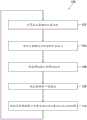
现在参见图3至图6,其为由图1的设备12绘制的示例性用户界面屏幕70的不同视图。参照被配置成插入活体受检者的身体部位内的医疗器械来描述用户界面屏幕70。探针20为医疗器械的一个示例。然而,医疗器械可包括任何合适的医疗器械,诸如用于插入到身体部位内的非消融探针、内窥镜、和/或外科工具(诸如ENT工具、抽吸工具、吸切器或剃刀)。身体部位可为任何合适的身体部位,例如但不限于心腔或鼻窦腔。用户界面屏幕70可利用任何合适的处理和显示系统来绘制,并且并不限于由设备12来绘制。Referring now to FIGS. 3-6 , which are various views of an exemplary
图3示出了包括身体部位的3D表示72的用户界面屏幕70。3D表示72示出了具有轮廓98的身体部位的外表面74以及移动窗口76,移动窗口76响应于医疗器械的经计算位置坐标而在3D表示72中的外表面74上移动,以便经由窗口76提供身体部位的3D表示72的内部视图80。因此,当医疗器械在身体部位内移动时,移动窗口76在外表面74上移动。为了简单起见,附图中仅标记了轮廓98中的一些。3 shows a
身体部位的3D表示72可由医师进行旋转和/或缩放和/或平移以示出3D表示72的任何视图。The
内部视图80包括医疗器械(或其部分)在经计算位置坐标处的3D表示82。内部视图80还可包括除医疗器械的3D表示82之外的一个或多个(2D或3D)元件。该元件可包括图形符号,诸如标记由消融探针执行的消融的位置的标签84,例如VisiTag。外表面74也可包括一个或多个附加元件,诸如标签84,例如VisiTag。为了简单起见,附图中仅标记了标签84中的一些。The
3D表示82和/或标签84可基于任何合适的方法来绘制,例如但不限于使用Zar等人的美国专利公布2018/0182157中的成像方法,该专利公布以引用方式并入本文。具体地,Zar等人的参考文献的第31至48段描述了在电解剖标测图上绘制二次曲面。二次曲面的示例包括球体、椭圆体、圆柱体、圆锥体、双曲线抛物面、抛物面以及双曲面。成像可包括使用医疗器械的机械数据并组合各种二次曲面以形成医疗器械的3D表示82的图像。The
内部视图80可包括设置在身体部位的3D表示72的内表面88上的色斑86。外表面74也可包括设置在其上的色斑86。色斑86可表示任何合适的标测,例如LAT或电压。设置在内表面88上的色斑86可表示与设置在外表面74上的色斑86相同或不同的标测。为了简单起见,附图中仅标记了色斑86中的一些。The
图4所示的用户界面屏幕70包括覆盖全部外表面74和内表面88的色斑86。The
图5和图6示出了包括具有网格构造92的网片90的移动窗口76,网片90沿循由移动窗口76替代的外表面74部分的轮廓98。网片90包括位于网格构造92中的间隙94。网格构造92及其轮廓有助于医师保持身体部位的外部视图与内部视图80之间的环境。透过网格构造92中的间隙94可以看见内部视图80,从而允许透过间隙94来观察医疗器械的3D表示82和标签84。为了简单起见,附图中仅标记了间隙94中的一些。FIGS. 5 and 6 illustrate a moving
在图5中,网格构造92由色斑96部分地着色,色斑96对应于分配到由移动窗口76替代的外表面74部分的色斑86。In FIG. 5 ,
在图6中,网格构造92由色斑96着色,色斑96对应于分配到由移动窗口76替代的外表面74部分的色斑86。为了简单起见,附图中仅标记了色斑96中的一些。另外,网格构造92中的一些间隙94根据设置在身体部位的3D表示72的内表面88上的透过间隙94可见的色斑86进行着色。In FIG. 6 ,
移动窗口76可具有任何合适的形状(例如,圆形、椭圆形或任意多边形)和任何合适的尺寸。计算移动窗口76的位置以包括医疗器械(或其部分诸如医疗器械的远侧端部)的3D表示82。The moving
在一些实施方案中,可按下述方式计算移动窗口76的位置。将医疗器械上的点(诸如尖端或医疗器械的远侧端部上的另一点)投影到身体部位的3D表示72的外表面74上。该点通常被投影到外表面74(当前存在于视图中)上的最靠近该点的第一位置处。因此,即使该点更靠近当前不存在于视图中的外表面74的部分上的第二位置,该点仍被投影到外表面74(当前存在于视图中)上的第一位置处。在其他实施方案中,如果该点更靠近当前不存在于视图中的外表面74的部分上的第二位置,则可由设备12旋转身体部位的3D表示72,使得最靠近该点的外表面74的第二位置和围绕第二位置设置的所得移动窗口76可在用户界面屏幕70中观察到。在其他实施方案中,该点沿着基本上垂直于(例如,在5度精度以内)外表面74的方向被投影到外表面74上。移动窗口76的周边则围绕外表面74上的投影点保持居中。在一些实施方案中,移动窗口的周边上的位置根据自投影点的相应等距线(例如,短程线或直线)的端部来限定,使得移动窗口76具有基本圆形形状,基本圆形形状通过身体部位的3D表示72的外表面74的轮廓而变形。In some implementations, the position of the moving
用户界面屏幕70的各种特征可为用户可配置的,例如但不限于网片90是否被示出、网格构造92的设计和/或厚度、网格构造92中的间隙94的尺寸和/或形状、色斑86是否显示在外表面74和网格构造92上、色斑86是否显示在外表面88上、移动窗口76的形状、移动窗口76的尺寸或半径、自投影周边距离是否以直线或短程线进行测量。仅以举例的方式,医师可利用弹出窗口、菜单选项和/或快捷键来控制上述特征。Various features of
现在参考图7,其为示出包括图1的系统12的操作方法中的示例性步骤的流程图100。处理电路51被配置成计算医疗器械在身体部位中的位置坐标(框102)。处理电路51被配置成将医疗器械的点投影到身体部位的3D表示72的外表面74上(框104)。在一些实施方案中,处理电路51被配置成将医疗器械的点沿基本上垂直于(例如,在5度精度以内)外表面的方向投影到外表面74上。在一些实施方案中,处理电路51被配置成将移动窗口76的周边上的位置限定为端接在自投影点的相应等距线(短程线或直线)的端部处(框106),使得移动窗口76具有基本圆形形状,基本圆形形状通过身体部位的3D表示72的外表面74的轮廓而变形。处理电路51被配置成限定围绕投影点保持居中的移动窗口76的周边(框108)。Reference is now made to FIG. 7 , which is a
在一些实施方案中,移动窗口76可具有任何合适的形状(例如,圆形、椭圆形或任意多边形)和任何合适的尺寸,其中移动窗口76的周边围绕投影点保持居中并且/或者被计算以包括医疗器械(或其部分诸如医疗器械的远侧端部)的3D表示82。In some embodiments, the moving
处理电路51被配置成将身体部位的3D表示72绘制到到显示器61(框110),从而显示具有移动窗口76的外表面74,移动窗口76响应于医疗器械的经计算位置坐标而在身体部位的3D表示72中的外表面74上移动,以便经由窗口76提供身体部位的3D表示72的内部视图80。3D表示72的绘制可仅以举例的方式包括上文参照图3至图6所述的特征的任何组合。The
为清晰起见,在独立实施方案的上下文中描述的本发明的各种特征也可在单个实施方案中组合提供。相反地,为简明起见,在单个实施方案的上下文中进行描述的本发明的各种特征也可单独地或以任何合适的子组合形式提供。Various features of the invention that are, for clarity, described in the context of separate embodiments, may also be provided in combination in a single embodiment. Conversely, various features of the invention that are, for brevity, described in the context of a single embodiment, may also be provided separately or in any suitable subcombination.
上述实施方案以举例的方式被引用,并且本发明不限于上文具体示出和描述的内容。相反,本发明的范围包括上文描述的各种特征的组合和子组合以及它们的变型和修改,本领域的技术人员在阅读上述描述时将会想到变型和修改,并且变型和修改并未在现有技术中公开。The above-described embodiments are cited by way of example, and the invention is not limited to what has been specifically shown and described above. Rather, the scope of the invention includes combinations and subcombinations of the various features described above, as well as variations and modifications thereof, which would occur to those skilled in the art upon reading the above description and that are not now disclosed in the technology.
Claims (21)
Translated fromChineseApplications Claiming Priority (2)
| Application Number | Priority Date | Filing Date | Title |
|---|---|---|---|
| US16/219,427US11350847B2 (en) | 2018-12-13 | 2018-12-13 | Composite visualization of body part |
| US16/219427 | 2018-12-13 |
Publications (2)
| Publication Number | Publication Date |
|---|---|
| CN111317562Atrue CN111317562A (en) | 2020-06-23 |
| CN111317562B CN111317562B (en) | 2024-06-11 |
Family
ID=68887214
Family Applications (1)
| Application Number | Title | Priority Date | Filing Date |
|---|---|---|---|
| CN201911278801.3AActiveCN111317562B (en) | 2018-12-13 | 2019-12-13 | Synthetic visualization of body parts |
Country Status (5)
| Country | Link |
|---|---|
| US (1) | US11350847B2 (en) |
| EP (1) | EP3666217B1 (en) |
| JP (1) | JP7423292B2 (en) |
| CN (1) | CN111317562B (en) |
| IL (1) | IL270418B2 (en) |
Families Citing this family (2)
| Publication number | Priority date | Publication date | Assignee | Title |
|---|---|---|---|---|
| WO2023105493A1 (en)* | 2021-12-10 | 2023-06-15 | Biosense Webster (Israel) Ltd. | Cardiac vein ablation visualization system and catheter |
| US12324669B2 (en)* | 2022-12-21 | 2025-06-10 | Biosense Webster (Israel) Ltd. | Detecting local activation source in atrial fibrillation |
Citations (11)
| Publication number | Priority date | Publication date | Assignee | Title |
|---|---|---|---|---|
| JPH11309139A (en)* | 1998-03-24 | 1999-11-09 | Siemens Ag | Computer tomography system |
| US20070225553A1 (en)* | 2003-10-21 | 2007-09-27 | The Board Of Trustees Of The Leland Stanford Junio | Systems and Methods for Intraoperative Targeting |
| US20090148012A1 (en)* | 2007-12-05 | 2009-06-11 | Andres Claudio Altmann | Anatomical modeling from a 3-d image and a surface mapping |
| US20100149213A1 (en)* | 2006-04-12 | 2010-06-17 | Nassir Navab | Virtual Penetrating Mirror Device for Visualizing of Virtual Objects within an Augmented Reality Environment |
| US20100312096A1 (en)* | 2009-06-08 | 2010-12-09 | Michael Guttman | Mri-guided interventional systems that can track and generate dynamic visualizations of flexible intrabody devices in near real time |
| US20130184569A1 (en)* | 2007-05-08 | 2013-07-18 | Gera Strommer | Method for producing an electrophysiological map of the heart |
| CN105640534A (en)* | 2014-11-28 | 2016-06-08 | 韦伯斯特生物官能(以色列)有限公司 | Differential mapping of body organ |
| US20170035287A1 (en)* | 2015-08-04 | 2017-02-09 | Novartis Ag | Dynamic surgical data overlay |
| CN107016662A (en)* | 2015-11-16 | 2017-08-04 | 韦伯斯特生物官能(以色列)有限公司 | Locally apply the transparency into CT images |
| CN108836478A (en)* | 2017-04-25 | 2018-11-20 | 韦伯斯特生物官能(以色列)有限公司 | Endoscopic views of the intrusive mood operation in slype |
| CN108882854A (en)* | 2016-03-21 | 2018-11-23 | 华盛顿大学 | Virtual reality or augmented reality visualization of 3D medical images |
Family Cites Families (8)
| Publication number | Priority date | Publication date | Assignee | Title |
|---|---|---|---|---|
| JPH11309A (en)* | 1997-06-12 | 1999-01-06 | Hitachi Ltd | Image processing device |
| US7536218B2 (en) | 2005-07-15 | 2009-05-19 | Biosense Webster, Inc. | Hybrid magnetic-based and impedance-based position sensing |
| US7756576B2 (en) | 2005-08-26 | 2010-07-13 | Biosense Webster, Inc. | Position sensing and detection of skin impedance |
| US8702609B2 (en) | 2007-07-27 | 2014-04-22 | Meridian Cardiovascular Systems, Inc. | Image-guided intravascular therapy catheters |
| US10299753B2 (en) | 2007-11-29 | 2019-05-28 | Biosense Webster, Inc. | Flashlight view of an anatomical structure |
| EP2452649A1 (en) | 2010-11-12 | 2012-05-16 | Deutsches Krebsforschungszentrum Stiftung des Öffentlichen Rechts | Visualization of anatomical data by augmented reality |
| CN111329553B (en) | 2016-03-12 | 2021-05-04 | P·K·朗 | Devices and methods for surgery |
| US20180182157A1 (en) | 2016-12-25 | 2018-06-28 | Biosense Webster (Israel) Ltd. | Fast rendering of quadrics |
- 2018
- 2018-12-13USUS16/219,427patent/US11350847B2/enactiveActive
- 2019
- 2019-11-04ILIL270418Apatent/IL270418B2/enunknown
- 2019-12-12JPJP2019224273Apatent/JP7423292B2/enactiveActive
- 2019-12-12EPEP19215467.2Apatent/EP3666217B1/enactiveActive
- 2019-12-13CNCN201911278801.3Apatent/CN111317562B/enactiveActive
Patent Citations (11)
| Publication number | Priority date | Publication date | Assignee | Title |
|---|---|---|---|---|
| JPH11309139A (en)* | 1998-03-24 | 1999-11-09 | Siemens Ag | Computer tomography system |
| US20070225553A1 (en)* | 2003-10-21 | 2007-09-27 | The Board Of Trustees Of The Leland Stanford Junio | Systems and Methods for Intraoperative Targeting |
| US20100149213A1 (en)* | 2006-04-12 | 2010-06-17 | Nassir Navab | Virtual Penetrating Mirror Device for Visualizing of Virtual Objects within an Augmented Reality Environment |
| US20130184569A1 (en)* | 2007-05-08 | 2013-07-18 | Gera Strommer | Method for producing an electrophysiological map of the heart |
| US20090148012A1 (en)* | 2007-12-05 | 2009-06-11 | Andres Claudio Altmann | Anatomical modeling from a 3-d image and a surface mapping |
| US20100312096A1 (en)* | 2009-06-08 | 2010-12-09 | Michael Guttman | Mri-guided interventional systems that can track and generate dynamic visualizations of flexible intrabody devices in near real time |
| CN105640534A (en)* | 2014-11-28 | 2016-06-08 | 韦伯斯特生物官能(以色列)有限公司 | Differential mapping of body organ |
| US20170035287A1 (en)* | 2015-08-04 | 2017-02-09 | Novartis Ag | Dynamic surgical data overlay |
| CN107016662A (en)* | 2015-11-16 | 2017-08-04 | 韦伯斯特生物官能(以色列)有限公司 | Locally apply the transparency into CT images |
| CN108882854A (en)* | 2016-03-21 | 2018-11-23 | 华盛顿大学 | Virtual reality or augmented reality visualization of 3D medical images |
| CN108836478A (en)* | 2017-04-25 | 2018-11-20 | 韦伯斯特生物官能(以色列)有限公司 | Endoscopic views of the intrusive mood operation in slype |
Also Published As
| Publication number | Publication date |
|---|---|
| EP3666217A1 (en) | 2020-06-17 |
| CN111317562B (en) | 2024-06-11 |
| JP7423292B2 (en) | 2024-01-29 |
| JP2020093102A (en) | 2020-06-18 |
| EP3666217C0 (en) | 2024-03-13 |
| US20200187825A1 (en) | 2020-06-18 |
| US11350847B2 (en) | 2022-06-07 |
| IL270418B1 (en) | 2023-03-01 |
| IL270418B2 (en) | 2023-07-01 |
| IL270418A (en) | 2020-06-30 |
| EP3666217B1 (en) | 2024-03-13 |
Similar Documents
| Publication | Publication Date | Title |
|---|---|---|
| EP3422297B1 (en) | System and method for glass state view in real-time three-dimensional (3d) cardiac imaging | |
| CN109419501B (en) | Advanced Current Location (ACL) automatic map rotation for detecting holes in Current Position Map (CPM) maps | |
| JP6719885B2 (en) | Positioning map using intracardiac signals | |
| CN101467894B (en) | Flashlight view of anatomical structure | |
| CN112617842A (en) | 3D intracardiac activity demonstration | |
| JP7366535B2 (en) | Graphical user interface (GUI) for displaying the estimated proximity of the cardiac catheter to the esophagus | |
| US20060116576A1 (en) | System and use thereof to provide indication of proximity between catheter and location of interest in 3-D space | |
| JP7460355B2 (en) | Medical User Interface | |
| JP2019063527A (en) | Interactive display of selected ECG channels | |
| CN111317562B (en) | Synthetic visualization of body parts | |
| JP2019063518A (en) | Estimation of ablation size and visual representation | |
| KR102850298B1 (en) | Map of body cavity | |
| JP7366534B2 (en) | Estimating the proximity of the cardiac catheter to the esophagus | |
| JP2025516867A (en) | Visualization of quality indicators indicating ablation stability at the ablation site | |
| JP2023016788A (en) | Accurate tissue proximity |
Legal Events
| Date | Code | Title | Description |
|---|---|---|---|
| PB01 | Publication | ||
| PB01 | Publication | ||
| SE01 | Entry into force of request for substantive examination | ||
| SE01 | Entry into force of request for substantive examination | ||
| GR01 | Patent grant | ||
| GR01 | Patent grant |