CN111315294A - System for controlling ablation therapy and visualization - Google Patents
System for controlling ablation therapy and visualizationDownload PDFInfo
- Publication number
- CN111315294A CN111315294ACN201880072306.4ACN201880072306ACN111315294ACN 111315294 ACN111315294 ACN 111315294ACN 201880072306 ACN201880072306 ACN 201880072306ACN 111315294 ACN111315294 ACN 111315294A
- Authority
- CN
- China
- Prior art keywords
- ablation
- energy
- stylets
- ultrasound
- cage
- Prior art date
- Legal status (The legal status is an assumption and is not a legal conclusion. Google has not performed a legal analysis and makes no representation as to the accuracy of the status listed.)
- Granted
Links
Images


Classifications
- A—HUMAN NECESSITIES
- A61—MEDICAL OR VETERINARY SCIENCE; HYGIENE
- A61B—DIAGNOSIS; SURGERY; IDENTIFICATION
- A61B5/00—Measuring for diagnostic purposes; Identification of persons
- A61B5/06—Devices, other than using radiation, for detecting or locating foreign bodies ; Determining position of diagnostic devices within or on the body of the patient
- A61B5/061—Determining position of a probe within the body employing means separate from the probe, e.g. sensing internal probe position employing impedance electrodes on the surface of the body
- A61B5/062—Determining position of a probe within the body employing means separate from the probe, e.g. sensing internal probe position employing impedance electrodes on the surface of the body using magnetic field
- A—HUMAN NECESSITIES
- A61—MEDICAL OR VETERINARY SCIENCE; HYGIENE
- A61B—DIAGNOSIS; SURGERY; IDENTIFICATION
- A61B8/00—Diagnosis using ultrasonic, sonic or infrasonic waves
- A61B8/12—Diagnosis using ultrasonic, sonic or infrasonic waves in body cavities or body tracts, e.g. by using catheters
- A—HUMAN NECESSITIES
- A61—MEDICAL OR VETERINARY SCIENCE; HYGIENE
- A61B—DIAGNOSIS; SURGERY; IDENTIFICATION
- A61B18/00—Surgical instruments, devices or methods for transferring non-mechanical forms of energy to or from the body
- A61B18/04—Surgical instruments, devices or methods for transferring non-mechanical forms of energy to or from the body by heating
- A61B18/042—Surgical instruments, devices or methods for transferring non-mechanical forms of energy to or from the body by heating using additional gas becoming plasma
- A—HUMAN NECESSITIES
- A61—MEDICAL OR VETERINARY SCIENCE; HYGIENE
- A61B—DIAGNOSIS; SURGERY; IDENTIFICATION
- A61B18/00—Surgical instruments, devices or methods for transferring non-mechanical forms of energy to or from the body
- A61B18/04—Surgical instruments, devices or methods for transferring non-mechanical forms of energy to or from the body by heating
- A61B18/12—Surgical instruments, devices or methods for transferring non-mechanical forms of energy to or from the body by heating by passing a current through the tissue to be heated, e.g. high-frequency current
- A61B18/14—Probes or electrodes therefor
- A61B18/1477—Needle-like probes
- A—HUMAN NECESSITIES
- A61—MEDICAL OR VETERINARY SCIENCE; HYGIENE
- A61B—DIAGNOSIS; SURGERY; IDENTIFICATION
- A61B18/00—Surgical instruments, devices or methods for transferring non-mechanical forms of energy to or from the body
- A61B18/04—Surgical instruments, devices or methods for transferring non-mechanical forms of energy to or from the body by heating
- A61B18/12—Surgical instruments, devices or methods for transferring non-mechanical forms of energy to or from the body by heating by passing a current through the tissue to be heated, e.g. high-frequency current
- A61B18/14—Probes or electrodes therefor
- A61B18/1485—Probes or electrodes therefor having a short rigid shaft for accessing the inner body through natural openings
- A—HUMAN NECESSITIES
- A61—MEDICAL OR VETERINARY SCIENCE; HYGIENE
- A61B—DIAGNOSIS; SURGERY; IDENTIFICATION
- A61B18/00—Surgical instruments, devices or methods for transferring non-mechanical forms of energy to or from the body
- A61B18/18—Surgical instruments, devices or methods for transferring non-mechanical forms of energy to or from the body by applying electromagnetic radiation, e.g. microwaves
- A61B18/1815—Surgical instruments, devices or methods for transferring non-mechanical forms of energy to or from the body by applying electromagnetic radiation, e.g. microwaves using microwaves
- A—HUMAN NECESSITIES
- A61—MEDICAL OR VETERINARY SCIENCE; HYGIENE
- A61B—DIAGNOSIS; SURGERY; IDENTIFICATION
- A61B34/00—Computer-aided surgery; Manipulators or robots specially adapted for use in surgery
- A61B34/20—Surgical navigation systems; Devices for tracking or guiding surgical instruments, e.g. for frameless stereotaxis
- A—HUMAN NECESSITIES
- A61—MEDICAL OR VETERINARY SCIENCE; HYGIENE
- A61B—DIAGNOSIS; SURGERY; IDENTIFICATION
- A61B34/00—Computer-aided surgery; Manipulators or robots specially adapted for use in surgery
- A61B34/25—User interfaces for surgical systems
- A—HUMAN NECESSITIES
- A61—MEDICAL OR VETERINARY SCIENCE; HYGIENE
- A61B—DIAGNOSIS; SURGERY; IDENTIFICATION
- A61B8/00—Diagnosis using ultrasonic, sonic or infrasonic waves
- A61B8/08—Clinical applications
- A61B8/0833—Clinical applications involving detecting or locating foreign bodies or organic structures
- A61B8/0841—Clinical applications involving detecting or locating foreign bodies or organic structures for locating instruments
- A—HUMAN NECESSITIES
- A61—MEDICAL OR VETERINARY SCIENCE; HYGIENE
- A61B—DIAGNOSIS; SURGERY; IDENTIFICATION
- A61B8/00—Diagnosis using ultrasonic, sonic or infrasonic waves
- A61B8/44—Constructional features of the ultrasonic, sonic or infrasonic diagnostic device
- A61B8/4416—Constructional features of the ultrasonic, sonic or infrasonic diagnostic device related to combined acquisition of different diagnostic modalities, e.g. combination of ultrasound and X-ray acquisitions
- A—HUMAN NECESSITIES
- A61—MEDICAL OR VETERINARY SCIENCE; HYGIENE
- A61B—DIAGNOSIS; SURGERY; IDENTIFICATION
- A61B8/00—Diagnosis using ultrasonic, sonic or infrasonic waves
- A61B8/46—Ultrasonic, sonic or infrasonic diagnostic devices with special arrangements for interfacing with the operator or the patient
- A61B8/461—Displaying means of special interest
- A61B8/463—Displaying means of special interest characterised by displaying multiple images or images and diagnostic data on one display
- A—HUMAN NECESSITIES
- A61—MEDICAL OR VETERINARY SCIENCE; HYGIENE
- A61B—DIAGNOSIS; SURGERY; IDENTIFICATION
- A61B8/00—Diagnosis using ultrasonic, sonic or infrasonic waves
- A61B8/46—Ultrasonic, sonic or infrasonic diagnostic devices with special arrangements for interfacing with the operator or the patient
- A61B8/461—Displaying means of special interest
- A61B8/465—Displaying means of special interest adapted to display user selection data, e.g. icons or menus
- A—HUMAN NECESSITIES
- A61—MEDICAL OR VETERINARY SCIENCE; HYGIENE
- A61B—DIAGNOSIS; SURGERY; IDENTIFICATION
- A61B8/00—Diagnosis using ultrasonic, sonic or infrasonic waves
- A61B8/46—Ultrasonic, sonic or infrasonic diagnostic devices with special arrangements for interfacing with the operator or the patient
- A61B8/461—Displaying means of special interest
- A61B8/466—Displaying means of special interest adapted to display 3D data
- A—HUMAN NECESSITIES
- A61—MEDICAL OR VETERINARY SCIENCE; HYGIENE
- A61B—DIAGNOSIS; SURGERY; IDENTIFICATION
- A61B8/00—Diagnosis using ultrasonic, sonic or infrasonic waves
- A61B8/46—Ultrasonic, sonic or infrasonic diagnostic devices with special arrangements for interfacing with the operator or the patient
- A61B8/467—Ultrasonic, sonic or infrasonic diagnostic devices with special arrangements for interfacing with the operator or the patient characterised by special input means
- A61B8/469—Ultrasonic, sonic or infrasonic diagnostic devices with special arrangements for interfacing with the operator or the patient characterised by special input means for selection of a region of interest
- A—HUMAN NECESSITIES
- A61—MEDICAL OR VETERINARY SCIENCE; HYGIENE
- A61B—DIAGNOSIS; SURGERY; IDENTIFICATION
- A61B90/00—Instruments, implements or accessories specially adapted for surgery or diagnosis and not covered by any of the groups A61B1/00 - A61B50/00, e.g. for luxation treatment or for protecting wound edges
- A61B90/36—Image-producing devices or illumination devices not otherwise provided for
- A61B90/361—Image-producing devices, e.g. surgical cameras
- A—HUMAN NECESSITIES
- A61—MEDICAL OR VETERINARY SCIENCE; HYGIENE
- A61B—DIAGNOSIS; SURGERY; IDENTIFICATION
- A61B17/00—Surgical instruments, devices or methods
- A61B2017/00017—Electrical control of surgical instruments
- A61B2017/00199—Electrical control of surgical instruments with a console, e.g. a control panel with a display
- A—HUMAN NECESSITIES
- A61—MEDICAL OR VETERINARY SCIENCE; HYGIENE
- A61B—DIAGNOSIS; SURGERY; IDENTIFICATION
- A61B17/00—Surgical instruments, devices or methods
- A61B2017/00017—Electrical control of surgical instruments
- A61B2017/00225—Systems for controlling multiple different instruments, e.g. microsurgical systems
- A—HUMAN NECESSITIES
- A61—MEDICAL OR VETERINARY SCIENCE; HYGIENE
- A61B—DIAGNOSIS; SURGERY; IDENTIFICATION
- A61B18/00—Surgical instruments, devices or methods for transferring non-mechanical forms of energy to or from the body
- A61B2018/00315—Surgical instruments, devices or methods for transferring non-mechanical forms of energy to or from the body for treatment of particular body parts
- A61B2018/00559—Female reproductive organs
- A—HUMAN NECESSITIES
- A61—MEDICAL OR VETERINARY SCIENCE; HYGIENE
- A61B—DIAGNOSIS; SURGERY; IDENTIFICATION
- A61B18/00—Surgical instruments, devices or methods for transferring non-mechanical forms of energy to or from the body
- A61B2018/00571—Surgical instruments, devices or methods for transferring non-mechanical forms of energy to or from the body for achieving a particular surgical effect
- A61B2018/00577—Ablation
- A—HUMAN NECESSITIES
- A61—MEDICAL OR VETERINARY SCIENCE; HYGIENE
- A61B—DIAGNOSIS; SURGERY; IDENTIFICATION
- A61B18/00—Surgical instruments, devices or methods for transferring non-mechanical forms of energy to or from the body
- A61B2018/00636—Sensing and controlling the application of energy
- A61B2018/00773—Sensed parameters
- A61B2018/00791—Temperature
- A—HUMAN NECESSITIES
- A61—MEDICAL OR VETERINARY SCIENCE; HYGIENE
- A61B—DIAGNOSIS; SURGERY; IDENTIFICATION
- A61B18/00—Surgical instruments, devices or methods for transferring non-mechanical forms of energy to or from the body
- A61B2018/00636—Sensing and controlling the application of energy
- A61B2018/00904—Automatic detection of target tissue
- A—HUMAN NECESSITIES
- A61—MEDICAL OR VETERINARY SCIENCE; HYGIENE
- A61B—DIAGNOSIS; SURGERY; IDENTIFICATION
- A61B18/00—Surgical instruments, devices or methods for transferring non-mechanical forms of energy to or from the body
- A61B18/02—Surgical instruments, devices or methods for transferring non-mechanical forms of energy to or from the body by cooling, e.g. cryogenic techniques
- A61B2018/0212—Surgical instruments, devices or methods for transferring non-mechanical forms of energy to or from the body by cooling, e.g. cryogenic techniques using an instrument inserted into a body lumen, e.g. catheter
- A—HUMAN NECESSITIES
- A61—MEDICAL OR VETERINARY SCIENCE; HYGIENE
- A61B—DIAGNOSIS; SURGERY; IDENTIFICATION
- A61B18/00—Surgical instruments, devices or methods for transferring non-mechanical forms of energy to or from the body
- A61B18/04—Surgical instruments, devices or methods for transferring non-mechanical forms of energy to or from the body by heating
- A61B18/12—Surgical instruments, devices or methods for transferring non-mechanical forms of energy to or from the body by heating by passing a current through the tissue to be heated, e.g. high-frequency current
- A61B18/14—Probes or electrodes therefor
- A61B2018/1405—Electrodes having a specific shape
- A61B2018/1425—Needle
- A61B2018/143—Needle multiple needles
- A—HUMAN NECESSITIES
- A61—MEDICAL OR VETERINARY SCIENCE; HYGIENE
- A61B—DIAGNOSIS; SURGERY; IDENTIFICATION
- A61B34/00—Computer-aided surgery; Manipulators or robots specially adapted for use in surgery
- A61B34/10—Computer-aided planning, simulation or modelling of surgical operations
- A61B2034/101—Computer-aided simulation of surgical operations
- A61B2034/102—Modelling of surgical devices, implants or prosthesis
- A61B2034/104—Modelling the effect of the tool, e.g. the effect of an implanted prosthesis or for predicting the effect of ablation or burring
- A—HUMAN NECESSITIES
- A61—MEDICAL OR VETERINARY SCIENCE; HYGIENE
- A61B—DIAGNOSIS; SURGERY; IDENTIFICATION
- A61B34/00—Computer-aided surgery; Manipulators or robots specially adapted for use in surgery
- A61B34/10—Computer-aided planning, simulation or modelling of surgical operations
- A61B2034/107—Visualisation of planned trajectories or target regions
- A—HUMAN NECESSITIES
- A61—MEDICAL OR VETERINARY SCIENCE; HYGIENE
- A61B—DIAGNOSIS; SURGERY; IDENTIFICATION
- A61B34/00—Computer-aided surgery; Manipulators or robots specially adapted for use in surgery
- A61B34/20—Surgical navigation systems; Devices for tracking or guiding surgical instruments, e.g. for frameless stereotaxis
- A61B2034/2046—Tracking techniques
- A61B2034/2051—Electromagnetic tracking systems
- A—HUMAN NECESSITIES
- A61—MEDICAL OR VETERINARY SCIENCE; HYGIENE
- A61B—DIAGNOSIS; SURGERY; IDENTIFICATION
- A61B34/00—Computer-aided surgery; Manipulators or robots specially adapted for use in surgery
- A61B34/20—Surgical navigation systems; Devices for tracking or guiding surgical instruments, e.g. for frameless stereotaxis
- A61B2034/2046—Tracking techniques
- A61B2034/2063—Acoustic tracking systems, e.g. using ultrasound
- A—HUMAN NECESSITIES
- A61—MEDICAL OR VETERINARY SCIENCE; HYGIENE
- A61B—DIAGNOSIS; SURGERY; IDENTIFICATION
- A61B34/00—Computer-aided surgery; Manipulators or robots specially adapted for use in surgery
- A61B34/20—Surgical navigation systems; Devices for tracking or guiding surgical instruments, e.g. for frameless stereotaxis
- A61B2034/2072—Reference field transducer attached to an instrument or patient
- A—HUMAN NECESSITIES
- A61—MEDICAL OR VETERINARY SCIENCE; HYGIENE
- A61B—DIAGNOSIS; SURGERY; IDENTIFICATION
- A61B90/00—Instruments, implements or accessories specially adapted for surgery or diagnosis and not covered by any of the groups A61B1/00 - A61B50/00, e.g. for luxation treatment or for protecting wound edges
- A61B90/36—Image-producing devices or illumination devices not otherwise provided for
- A61B2090/364—Correlation of different images or relation of image positions in respect to the body
- A61B2090/365—Correlation of different images or relation of image positions in respect to the body augmented reality, i.e. correlating a live optical image with another image
- A—HUMAN NECESSITIES
- A61—MEDICAL OR VETERINARY SCIENCE; HYGIENE
- A61B—DIAGNOSIS; SURGERY; IDENTIFICATION
- A61B90/00—Instruments, implements or accessories specially adapted for surgery or diagnosis and not covered by any of the groups A61B1/00 - A61B50/00, e.g. for luxation treatment or for protecting wound edges
- A61B90/36—Image-producing devices or illumination devices not otherwise provided for
- A61B90/37—Surgical systems with images on a monitor during operation
- A61B2090/378—Surgical systems with images on a monitor during operation using ultrasound
- A—HUMAN NECESSITIES
- A61—MEDICAL OR VETERINARY SCIENCE; HYGIENE
- A61B—DIAGNOSIS; SURGERY; IDENTIFICATION
- A61B90/00—Instruments, implements or accessories specially adapted for surgery or diagnosis and not covered by any of the groups A61B1/00 - A61B50/00, e.g. for luxation treatment or for protecting wound edges
- A61B90/39—Markers, e.g. radio-opaque or breast lesions markers
- A61B2090/397—Markers, e.g. radio-opaque or breast lesions markers electromagnetic other than visible, e.g. microwave
- A61B2090/3975—Markers, e.g. radio-opaque or breast lesions markers electromagnetic other than visible, e.g. microwave active
- A61B2090/3979—Markers, e.g. radio-opaque or breast lesions markers electromagnetic other than visible, e.g. microwave active infrared
- A—HUMAN NECESSITIES
- A61—MEDICAL OR VETERINARY SCIENCE; HYGIENE
- A61M—DEVICES FOR INTRODUCING MEDIA INTO, OR ONTO, THE BODY; DEVICES FOR TRANSDUCING BODY MEDIA OR FOR TAKING MEDIA FROM THE BODY; DEVICES FOR PRODUCING OR ENDING SLEEP OR STUPOR
- A61M25/00—Catheters; Hollow probes
- A61M25/0067—Catheters; Hollow probes characterised by the distal end, e.g. tips
- A61M25/0082—Catheter tip comprising a tool
- A61M2025/0096—Catheter tip comprising a tool being laterally outward extensions or tools, e.g. hooks or fibres
Landscapes
- Health & Medical Sciences (AREA)
- Life Sciences & Earth Sciences (AREA)
- Engineering & Computer Science (AREA)
- Surgery (AREA)
- Animal Behavior & Ethology (AREA)
- Veterinary Medicine (AREA)
- Public Health (AREA)
- General Health & Medical Sciences (AREA)
- Biomedical Technology (AREA)
- Heart & Thoracic Surgery (AREA)
- Medical Informatics (AREA)
- Molecular Biology (AREA)
- Nuclear Medicine, Radiotherapy & Molecular Imaging (AREA)
- Physics & Mathematics (AREA)
- Pathology (AREA)
- Biophysics (AREA)
- Radiology & Medical Imaging (AREA)
- Otolaryngology (AREA)
- Plasma & Fusion (AREA)
- Human Computer Interaction (AREA)
- Robotics (AREA)
- Computer Graphics (AREA)
- General Engineering & Computer Science (AREA)
- Oral & Maxillofacial Surgery (AREA)
- Electromagnetism (AREA)
- Surgical Instruments (AREA)
- Ultra Sonic Daignosis Equipment (AREA)
Abstract
Description
Translated fromChinese相关申请的交叉引用CROSS-REFERENCE TO RELATED APPLICATIONS
本申请要求2017年11月9日提交的美国临时申请62/583,972的优先权权益,该临时申请通过援引以其全文并入本文。This application claims the benefit of priority to US Provisional Application 62/583,972, filed November 9, 2017, which is incorporated herein by reference in its entirety.
技术领域technical field
本发明涉及用于放置在患者体内以消融肿瘤(诸如子宫纤维瘤)的医疗装置的控制机构,更具体地涉及一种组织消融治疗装置,该组织消融治疗装置在无缝衔接的系统中协调能量递送、成像和导航控制。The present invention relates to a control mechanism for a medical device for placement in a patient to ablate tumors, such as uterine fibroids, and more particularly to a tissue ablation therapy device that coordinates energy in a seamless system Delivery, imaging and navigation controls.
背景技术Background technique
现今,外科医生使用各种形式的成像来实现或帮助各种各样的外科手术程序。成像允许减少附带损伤并缩短恢复时间以及提高存活率的更精确操作。Today, surgeons use various forms of imaging to perform or assist in a wide variety of surgical procedures. Imaging allows for more precise manipulations that reduce collateral damage and shorten recovery time as well as improve survival.
成像系统可以使用各种各样的技术。这些成像系统在执行微创外科手术程序时特别有价值,其中通过使外科手术器械的宽度最小化并通过细长的小直径引导和支撑构件将它们引入到体内来促成最小化对健康组织的损伤的期望。Imaging systems can use a variety of techniques. These imaging systems are particularly valuable when performing minimally invasive surgical procedures, where minimal damage to healthy tissue is facilitated by minimizing the width of surgical instruments and introducing them into the body through elongated, small diameter guide and support members expectations.
例如,外科手术浸渍器可以被支撑在电缆和护套机械驱动系统的端部处,其中电缆和护套起到驱动浸渍器并将其引导到将要执行外科手术的点的附加功能。这样的浸渍器可以包括具有光学器件的光纤束,光学器件用于使浸渍器附近的组织周围成像并将该图像传递到例如具有LCD显示器的显示系统,以将图像呈现给外科医生来允许他快速且可靠地对不利的组织做手术。For example, a surgical impregnator may be supported at the end of a cable and sheath mechanical drive system, where the cable and sheath serve the additional function of driving the impregnator and guiding it to the point where the surgical procedure is to be performed. Such an immersion device may include a fiber optic bundle with optics for imaging the tissue surrounding the immersion device and transmitting the image to a display system such as an LCD display to present the image to the surgeon to allow him to quickly And reliably operate on unfavorable tissue.
其他方法包括将具有成像光学器件的光纤束的端部引入到现存的体腔或通道中,并且将图像传输到光纤束的另一端部,在该另一端部,可以通过聚焦光学器件和图像传感器(诸如CCD换能器)来接收该图像。此类装置可以具有小口径,例如,足够窄以进入鼻部并被引入到喉咙中。Other methods include introducing the end of a fiber optic bundle with imaging optics into an existing body cavity or channel, and transmitting the image to the other end of the fiber optic bundle, where it can be accessed by focusing optics and an image sensor ( such as a CCD transducer) to receive the image. Such devices may have a small bore, eg, narrow enough to enter the nose and be introduced into the throat.
又一种可能性是例如通过对腹腔吹气来在体内形成空腔。然后可以将该空腔用作成像空间,从而允许光学摄像头通过光学生成的图像向外科医生告知器械的位置和取向以及正在手术的解剖学特征,由此允许外科医生执行外科手术。Yet another possibility is to create a cavity in the body, eg by blowing air into the abdominal cavity. This cavity can then be used as an imaging space, allowing the optical camera to inform the surgeon through the optically generated images of the position and orientation of the instruments and the anatomy being operated on, thereby allowing the surgeon to perform the surgical procedure.
可以通过使用超声成像来实现不同维度的可视化。例如,超声换能器可以定位成抵靠器官的表面以生成器官的内部的图像。这种成像可以用于示出器官内部的解剖学特征和器械(诸如消融探针)的位置。Visualization in different dimensions can be achieved by using ultrasound imaging. For example, an ultrasound transducer may be positioned against a surface of an organ to generate an image of the interior of the organ. Such imaging can be used to show anatomical features inside the organ and the location of instruments such as ablation probes.
此类系统在外科手术程序期间特别有价值,因为它们增加了外科医生在外科手术程序(诸如消融诸如子宫纤维瘤的不希望的解剖学物体)期间可得到的信息量。Such systems are particularly valuable during surgical procedures because they increase the amount of information available to the surgeon during surgical procedures, such as ablation of unwanted anatomical objects such as uterine fibroids.
然而,此类系统典型地要求使用彼此分离的多个部件,这些部件可以以不同的方式呈现多个信息源。例如,成像系统、导航地图系统、组织消融系统等可以各自要求其自己的设备并参与利用装置,并且还可能呈现拥挤的手术室。这可能会导致结果和治疗混乱。However, such systems typically require the use of separate components that may present multiple sources of information in different ways. For example, imaging systems, navigation map systems, tissue ablation systems, etc. may each require their own equipment and participate in utilizing the apparatus, and may also present a crowded operating room. This can lead to confusion in results and treatment.
因此,需要一种可以将多个子系统组合成用于治疗患者体内的组织的衔接无缝系统的综合系统。Therefore, there is a need for an integrated system that can combine multiple subsystems into a cohesive seamless system for treating tissue in a patient.
发明内容SUMMARY OF THE INVENTION
提供了一种系统,该系统提供第一类型的第一成像装置,该第一成像装置具有第一图像输出,该第一成像装置被定位成对经受外科手术的区域进行成像。第二类型的第二成像装置具有第二图像输出并且被定位成对经受外科手术的区域进行成像。计算机进行耦合以接收第一图像输出和第二图像输出并且将第一图像输出和第二图像输出合并成表示整体图像的整体图像输出。驻留在计算机中的软件生成图形用户界面,该图形用户界面包括菜单项和子菜单项。外科手术装置耦合到计算机。驻留在所述计算机中的软件接收并显示从外科手术装置接收到的信息和/或控制外科手术装置的操作。显示器耦合到计算机以用于显示图形用户界面和整体图像。A system is provided that provides a first imaging device of a first type, the first imaging device having a first image output, the first imaging device being positioned to image an area undergoing a surgical procedure. A second imaging device of a second type has a second image output and is positioned to image the area undergoing surgery. A computer is coupled to receive the first image output and the second image output and to combine the first image output and the second image output into an overall image output representing the overall image. Software resident in the computer generates a graphical user interface that includes menu items and sub-menu items. The surgical device is coupled to the computer. Software resident in the computer receives and displays information received from and/or controls the operation of the surgical device. A display is coupled to the computer for displaying the graphical user interface and overall image.
可以通过将简化的按钮阵列与图形用户界面(″GUI″)结合使用来控制发明的消融装置。发明的GUI图形地描绘子宫消融探针,这允许内科医生看到程序以及消融过程中的每个步骤的参数和结果。The inventive ablation device can be controlled through the use of a simplified array of buttons in conjunction with a graphical user interface ("GUI"). The invented GUI graphically depicts the uterine ablation probe, which allows the physician to see the parameters and results of the procedure and each step in the ablation process.
发明的基于GUI的系统优于常规字母数字控制的优点是能够以直观的方式在视觉上显示装置的操作参数以及与特定患者相关联的医疗数据。同时,发明的装置提供直观且简化的手段来控制消融能量的施加。通过这种方式,装置更容易使用和配置,并且向外科医生提供程序和关于装置的操作的数据的更佳图片。An advantage of the inventive GUI-based system over conventional alphanumeric controls is the ability to visually display the operating parameters of the device and medical data associated with a particular patient in an intuitive manner. At the same time, the inventive device provides an intuitive and simplified means to control the application of ablation energy. In this way, the device is easier to use and configure, and provides the surgeon with a better picture of the procedure and data regarding the operation of the device.
因此,系统可以由不同部件组成综合整体系统,该综合整体系统可以集成RF消融部件、超声系统和导向地图系统。这些部件的组合可以允许使用者无缝地集成超声和引导以有助于相对于供治疗的组织来定位消融探针。各种单独部件组合到无缝系统中使得能够连续监测、反馈和准确治疗,因为超声探针可以通信并获得即时反馈以更好地管理治疗结果。例如,使超声探针与引导系统协作地工作使得引导能够实时地集成、解译并响应于超声图像。Therefore, the system can be composed of different components to form an integrated overall system, which can integrate RF ablation components, ultrasound system and guidance map system. The combination of these components may allow the user to seamlessly integrate ultrasound and guidance to help position the ablation probe relative to the tissue being treated. The combination of various individual components into a seamless system enables continuous monitoring, feedback and accurate treatment as the ultrasound probe can communicate and get instant feedback to better manage treatment outcomes. For example, having the ultrasound probe work cooperatively with the guidance system enables the guidance to integrate, interpret, and respond to ultrasound images in real-time.
因此,可以使用单个控制台来将不同部件中的每一者和计算机集成到整体相干系统中,该整体相干系统利于每个子系统之间的通信。因此,RF消融部件可以使消融探针与由导向地图系统生成的电磁场交互,以生成用于空间跟踪的消融探针位置信息。计算机可以对超声探针位置信息作出响应,并且消融探针可以生成示出超声图像与消融探针之间的位置关系的图形表示,以引导消融探针放置到通过超声探针成像的解剖学位置。因此,在一个实施例中,计算机和接口以及接口和消融能量源及超声机可以全部集成到单个控制台中。Thus, a single console can be used to integrate each of the different components and the computer into an overall coherent system that facilitates communication between each subsystem. Thus, the RF ablation component can interact the ablation probe with the electromagnetic field generated by the guide map system to generate ablation probe location information for spatial tracking. The computer can be responsive to the ultrasound probe position information and the ablation probe can generate a graphical representation showing the positional relationship between the ultrasound image and the ablation probe to guide placement of the ablation probe to the anatomical location imaged by the ultrasound probe . Thus, in one embodiment, the computer and interface as well as the interface and ablation energy source and ultrasound machine can all be integrated into a single console.
设备另外地包括显示装置,该显示装置对计算装置作出响应以便显示图形表示。显示器可以包括在GUI上显示的导向动画,该导向动画由处理引导信息的计算装置生成。使用者可以在导向动画中观看到实时校正信息。The apparatus additionally includes a display device responsive to the computing device to display the graphical representation. The display may include a guide animation displayed on the GUI, the guide animation being generated by a computing device that processes the guide information. Users can view real-time correction information in the guided animation.
引导系统可以使用电磁空间跟踪来计算限定的体积内的传感器的位置和取向。因此,传感器可以嵌入在消融探针和超声探针的端头中或者嵌入在具有传感器的超声换能器套筒内或沿着该超声换能器套筒。计算机可以确定在患者腹腔内相对于彼此的位置和取向,并且在GUI上显示代表性动画图像。获得的超声图像可以与代表性动画图像一起显示在无缝集成图像中。The guidance system can use electromagnetic space tracking to calculate the position and orientation of the sensors within the defined volume. Thus, the sensor may be embedded in the tip of the ablation probe and the ultrasound probe or within or along the ultrasound transducer sleeve with the sensor. The computer can determine the position and orientation relative to each other within the patient's abdominal cavity and display representative animated images on the GUI. Acquired ultrasound images can be displayed in a seamlessly integrated image along with representative animated images.
鉴于多个图像和器械的集成,可以存在用于相对于患者和执业医生定位显示监视器以利于治疗程序的若干配置。Given the integration of multiple images and instruments, there may be several configurations for positioning the display monitor relative to the patient and practitioner to facilitate treatment procedures.
现在转到可以集成不同的部件中的每一者的控制台,控制台的一个变型可以被配置为从各种部件中的每一者接收连接或信号以将它们集成到无缝用户界面中。控制台可以耦合到监视器,诸如用于显示生成的信息的医院拥有的辅助监视器。脚踏板(例如,气动双脚踏板)可以耦合到控制台并且用来选择性地激活消融探针,使得可以打开和关闭RF能量。Turning now to a console that can integrate each of the different components, a variation of the console can be configured to receive connections or signals from each of the various components to integrate them into a seamless user interface. The console may be coupled to a monitor, such as a hospital-owned auxiliary monitor for displaying the generated information. A foot pedal (eg, a pneumatic dual foot pedal) can be coupled to the console and used to selectively activate the ablation probe so that the RF energy can be turned on and off.
一个或多个衬垫(例如,可抛式一组2个单元)也可以经由衬垫电缆耦合到控制台,以用于为消融手机施加的RF能量提供返回路径。消融手机可以另外地经由手机电缆耦合到控制台。消融手机可以是被配置为递送程序中所使用的RF能量的可抛式手机,并且还可以容纳引导传感器。One or more pads (eg, a disposable set of 2 units) may also be coupled to the console via a pad cable for providing a return path for RF energy applied by the ablation handpiece. The ablation handset may additionally be coupled to the console via the handset cable. The ablation handpiece may be a disposable handpiece configured to deliver RF energy used in the procedure, and may also house a guidance sensor.
为了提供超声图像和引导,系统可以利用超声换能器,该超声换能器可以由连接到与换能器套筒结合使用的控制台的刚性探针组成,该换能器套筒充当容纳超声换能器和磁引导传感器的套筒,该磁引导传感器连接到与换能器分开的控制台。替代性地,可以使用具有集成的磁引导传感器的超声换能器的另一实施例,以代替换能器和套筒组合。To provide ultrasound images and guidance, the system may utilize an ultrasound transducer, which may consist of a rigid probe connected to a console used in conjunction with a transducer sleeve that acts to contain the ultrasound A sleeve for the transducer and a magnetically guided sensor attached to a console separate from the transducer. Alternatively, another embodiment of an ultrasonic transducer with an integrated magnetic guidance sensor may be used in place of the transducer and sleeve combination.
关于电磁场发生器,桌面场发生器(TTFG)或平面场发生器(PFG)可以用于连接到控制台,具体取决于可用的医院病床的类型。TTFG可以生成由手机和超声换能器套筒中的磁引导传感器(或具有传感器的换能器)获得的磁场,而PFG可以生成由手机和超声换能器套筒中的磁引导传感器(或具有传感器的换能器)获得的磁场。Regarding electromagnetic field generators, table top field generators (TTFG) or planar field generators (PFG) can be used to connect to the console, depending on the type of hospital bed available. TTFG can generate the magnetic field obtained by the magnetically guided sensor (or transducer with sensor) in the cell phone and ultrasonic transducer sleeve, while PFG can generate the magnetic field obtained by the magnetically guided sensor in the cell phone and ultrasonic transducer sleeve (or The magnetic field obtained by a transducer with a sensor).
在使用期间,当从消融装置部署管心针时,管心针的部署长度可以从部分延伸配置的任何长度调整到完全延伸配置。取决于从消融装置部署的管心针的长度,围绕管心针的消融区的大小也将相应地改变。因此,使用者可以调整消融区的大小以与例如纤维瘤的大小匹配或相关,以及最小化对被治疗区域周围的组织区域的消融。During use, when the stylet is deployed from the ablation device, the deployed length of the stylet can be adjusted from any length in the partially extended configuration to the fully extended configuration. Depending on the length of the stylet deployed from the ablation device, the size of the ablation zone surrounding the stylet will also vary accordingly. Thus, the user can adjust the size of the ablation zone to match or correlate with, for example, the size of the fibroid, as well as to minimize ablation of the tissue area surrounding the treated area.
为了便于确定治疗区域的大小,可以向使用者提供消融区的视觉表示,使得使用者不仅可以快速地确认消融装置相对于治疗区的定位是足够的,而且确认管心针的部署长度适合于产生足够大小的消融区。因此,可以提供基于指定的参数来自动地生成消融区的视觉表示的动态成像系统。To facilitate sizing of the treatment area, the user may be provided with a visual representation of the ablation area so that the user can quickly confirm not only that the positioning of the ablation device relative to the treatment area is adequate, but also that the deployment length of the stylet is suitable for producing Adequately sized ablation zone. Accordingly, a dynamic imaging system can be provided that automatically generates a visual representation of the ablation zone based on specified parameters.
一种用于使组织治疗可视化的系统总体上可以包括:组织治疗器械,该组织治疗器械具有一个或多个可部署的管心针和第一能量传感器;以及超声成像器械,该超声成像器械可以被配置为生成超声成像平面并且进一步具有第二能量传感器。另外地,还可以包括能量场发生器,该能量场发生器被配置为靠近患者身体放置并且可以进一步被配置为生成指示该第一能量传感器和该第二能量传感器相对于彼此的位置的输出。此外,该系统还可以包括控制台,该控制台与该治疗器械、该超声成像器械和该能量场发生器通信,其中,该控制台被配置为基于该一个或多个管心针的部署位置来生成相对于该超声成像平面定向的组织消融器械和消融边界或治疗区的代表性图像。A system for visualizing tissue treatment can generally include: a tissue treatment instrument having one or more deployable stylets and a first energy sensor; and an ultrasound imaging instrument that can is configured to generate an ultrasound imaging plane and further has a second energy sensor. Additionally, an energy field generator can be included that is configured to be placed proximate the patient's body and can be further configured to generate an output indicative of the position of the first energy sensor and the second energy sensor relative to each other. Additionally, the system can include a console in communication with the therapeutic instrument, the ultrasound imaging instrument, and the energy field generator, wherein the console is configured based on the deployment position of the one or more stylets to generate representative images of the tissue ablation instrument and the ablation boundary or treatment zone oriented relative to the ultrasound imaging plane.
一种使组织治疗可视化的方法总体上可以包括:从组织治疗器械接收第一输入,该组织治疗器械具有一个或多个可部署的管心针和第一能量传感器;以及从超声成像器械接收第二输入,该超声成像器械被配置为生成超声成像平面并且进一步具有第二能量传感器。可以基于从靠近患者身体放置的能量场发生器接收到的输出来显示组织消融器械相对于该超声成像器械的位置和取向,其中,该输出指示该第一能量传感器和该第二能量传感器相对于彼此的位置和取向,并且还可以基于该一个或多个管心针的部署位置来显示消融边界或治疗区的代表性图像。A method of visualizing tissue treatment may generally include: receiving a first input from a tissue treatment instrument having one or more deployable stylets and a first energy sensor; and receiving a first input from an ultrasound imaging instrument. Two inputs, the ultrasound imaging instrument is configured to generate an ultrasound imaging plane and further has a second energy sensor. The position and orientation of the tissue ablation instrument relative to the ultrasound imaging instrument can be displayed based on output received from an energy field generator placed proximate to the patient's body, wherein the output indicates the first energy sensor and the second energy sensor relative to the ultrasound imaging instrument. position and orientation to each other, and may also display a representative image of the ablation boundary or treatment zone based on the deployment position of the one or more stylets.
一种用于组织治疗的系统总体上可以包括:非暂时性计算机可读介质,该非暂时性计算机可读介质用于存储计算机可读程序代码;以及处理器,该处理器与该非暂时性计算机可读介质通信,该处理器被配置为执行操作,这些操作包括:显示消融装置的图像,该消融装置具有一个或多个可部署的管心针;基于该一个或多个管心针的部署位置来确定消融边界或笼的大小;以及将该消融边界或笼显示给使用者。A system for tissue treatment may generally include: a non-transitory computer-readable medium for storing computer-readable program code; and a processor associated with the non-transitory computer-readable medium in communication with a computer-readable medium, the processor configured to perform operations comprising: displaying an image of an ablation device having one or more deployable stylets; The deployment location determines the size of the ablation boundary or cage; and the ablation boundary or cage is displayed to the user.
一种消融方法总体上可以包括:显示消融装置的图像,该消融装置具有一个或多个可部署的管心针;在该一个或多个管芯针从该消融装置被推进时跟踪该一个或多个管心针的部署位置;基于该一个或多个管心针的部署位置来确定消融边界或笼的大小;以及将该消融边界或笼显示给使用者。An ablation method may generally include: displaying an image of an ablation device having one or more deployable stylets; tracking the one or more stylets as the one or more stylets are advanced from the ablation device deployment locations of a plurality of stylets; determining a size of an ablation boundary or cage based on the deployment locations of the one or more stylets; and displaying the ablation boundary or cage to a user.
本文中描述的成像和显示系统可以与2011年3月23日提交的美国专利申请13/069,497(美国公开2012/0245576)中描述的装置和方法以任何组合一起使用,该专利申请通过援引以其全文并出于任何目的并入本文。The imaging and display systems described herein can be used in any combination with the devices and methods described in US Patent Application 13/069,497, filed March 23, 2011 (US Publication 2012/0245576), which is incorporated by reference Incorporated herein in its entirety and for any purpose.
附图说明Description of drawings
在结合附图阅读时,可以从优选实施例的以下描述中获得对本发明的全面理解,在附图中:A full understanding of the invention can be obtained from the following description of the preferred embodiments, when read in conjunction with the accompanying drawings, in which:
图1A展示了可与发明系统一起使用的消融装置。Figure 1A illustrates an ablation device that can be used with the inventive system.
图1B展示了根据发明系统的结合计算机控制的消融系统。Figure IB illustrates an ablation system incorporating computer control in accordance with the inventive system.
图1C示出了图形用户界面屏幕,其中显示了菜单″纤维瘤数据″、″描述语″、″总结″、″选择程序″、″准备消融″和″准备电凝″,并且导航工具已经滚动到菜单选项″纤维瘤数据″。Figure 1C shows the GUI screen with the menus "Fibroid Data", "Descriptor", "Summary", "Select Procedure", "Prepare for Ablation" and "Prepare for Coagulation" displayed and the navigation tools have scrolled Go to the menu option "Fibroid Data".
图2展示了替代性发明系统,其中成像数据显示在GUI上。Figure 2 illustrates an alternative inventive system in which imaging data is displayed on a GUI.
图3展示了替代性发明系统,其中来自两个不同图像源的成像数据被合并并显示在GUI上。Figure 3 illustrates an alternative inventive system in which imaging data from two different image sources are combined and displayed on a GUI.
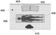
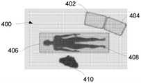
图4A至图4D展示了用于相对于患者来定位显示监视器的各种配置的代表性示例。4A-4D illustrate representative examples of various configurations for positioning a display monitor relative to a patient.
图5展示了被配置为从各种部件中的每一个接收连接或信号以将它们集成到无缝用户界面中的控制台的一个变型的说明性透视图。5 shows an illustrative perspective view of one variation of a console configured to receive connections or signals from each of the various components to integrate them into a seamless user interface.
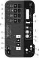
图6展示了控制台的一个变型,示出了各种控件和接口连接。Figure 6 shows a variation of the console showing the various controls and interface connections.
图7A和图7B展示了用于相对于手术室台来定位电磁场发生器的不同变型的透视图。7A and 7B illustrate perspective views of different variations for positioning the electromagnetic field generator relative to the operating room table.
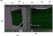
图8A和图8D展示了来自消融探针手机和超声探针的位置和取向信息可以如何由控制台组合到综合用户界面中。Figures 8A and 8D illustrate how position and orientation information from the ablation probe handpiece and ultrasound probe can be combined from the console into a comprehensive user interface.
图9A至图9C展示了视觉表示中的管心针的部署和相应地确定大小的消融区的图形表示。Figures 9A-9C illustrate graphical representations of deployment of a stylet and correspondingly sized ablation zone in a visual representation.
图10A至图10C展示了探针和超声图像在单独的监视器上或在与消融装置相同的GUI上的同时图像。Figures 10A-10C show simultaneous images of probe and ultrasound images on separate monitors or on the same GUI as the ablation device.
图11A至图11C展示了在图像上显示的具有选定的部署长度的部署的管心针及其对应的消融边界或笼的一个示例。11A-11C illustrate one example of a deployed stylet with a selected deployment length and its corresponding ablation boundary or cage displayed on an image.
图12A至图12C展示了超声图像与消融边界或笼之间的相交处的同时图像。Figures 12A-12C show simultaneous images of the ultrasound image and the intersection between the ablation boundary or cage.
图13A至图13C展示了示出对于管心针在消融边界或笼中的给定部署长度的代表性消融大小的长度和宽度的代表性图。13A-13C show representative graphs showing the length and width of representative ablation sizes for a given deployment length of the stylet in the ablation boundary or cage.
图13D展示了具有以某一角度部署的一个或多个管心针的消融装置。Figure 13D shows an ablation device with one or more stylets deployed at an angle.
具体实施方式Detailed ways
图1A是可用于实践发明系统的多天线或管心针式消融套管针器械1的透视图。消融器械1包括容纳多个管心针20的套管2以及可选地多个锚固件4。套管针尖端5设置在套管2的远端处。至少一个导体6设置在套管2内。导体6电联接到管心针20和套管针尖端4,并且因此向管心针20和套管针尖端5提供RF能量。根据本发明,管心针20和套管针尖端5彼此电联接并且与消融器械1的其他暴露部分电隔离。管心针20和套管针尖端5位于消融器械1的远端处。管心针各自由薄的丝状管状构件组成并且在程序期间最初完全容纳在套管2内。在其他变型中,管心针20和套管针尖端5反而可以被配置为除了RF消融能量之外还施加其他形式的能量。例如,消融器械反而可以被配置为递送例如冷冻消融能量、等离子能量、机械能量(诸如磨蚀、切割等)或其他形式的能量。Figure 1A is a perspective view of a multi-antenna or stylet
通过在向前方向上朝向消融器械1的远端被推进而经由开口7离开消融器械1来部署管心针20以用于消融。在管心针20被推进穿过开口7时,它们靠在偏转表面8上。偏转表面8被限定在金属主体中,该金属主体限定位于套管2的远端处的套管针尖端5。The
在发明系统的使用期间,在套管2的远端处的套管针尖端5用于在发明消融装置1的使用期间首先刺穿纤维瘤的组织。可选地,也容纳在消融器械1内的多个锚固件9可以朝向消融器械1的近端向后部署。在部署期间,锚固件9被偏转表面11偏转以移动到图1所示的位置。在部署之后,锚固件9可以可选地用于防止套管针尖端5在管心针20的部署期间向后移动。During use of the inventive system, the trocar tip 5 at the distal end of the
通过使用容纳在套管2内并在其近端处联接到操作手柄的可滑动地安装的手术员构件13来部署管心针20。也通过使用容纳在套管2内并在其近端处联接到操作手柄的可滑动地安装的手术员构件(未示出)来部署锚固件9。手术员构件13的远端联接到管心针3,这些管心针因此可以一致地被推进相同距离。锚固件和管心针的缩回和部署由如图1B所示的手术员手柄3控制。The
参考图1C,示出了图形用户界面(GUI)10显示屏幕。外科医生可以使用医疗装置,诸如消融装置。消融装置在GUI 10中由消融装置图示16来展示。消融装置用于消融组织块。GUI 10和导航按钮矩阵便于消融装置的使用,以最小化破坏术野的无菌性的可能性。GUI10显示菜单项12的选项,执业医生可以通过按下导航按钮矩阵上的滚动按钮23(图1B)来滚动这些菜单项,该滚动按钮在其表面上带有两个凸点23a。同时显示所有的菜单项12。菜单项12允许外科医生或其他执业医生输入患者数据、收集患者数据以及执行外科手术程序,这些都是在无菌术野内。当到达期望的菜单时,外科医生通过按下导航按钮矩阵上的选择按钮25来从菜单项12中进行选择,该选择按钮在其顶表面上具有一个凸点25a,该导航按钮矩阵可以整体被视作导航工具。当消融诸如纤维瘤的组织块时,菜单12选项包括″纤维瘤″编号数据、″纤维瘤数据″、″描述语″、″总结″、″选择程序″、″准备消融″和″准备电凝″。在图1B中,系统指示正在收集关于第一纤维瘤″纤维瘤1″的信息。箭头指示器指示外科医生已经滚动到″纤维瘤数据″菜单项。重复按下滚动按钮致使箭头指示器依次移动通过包括标记为以下的菜单项的选项:针对纤维瘤编号的″纤维瘤″、″纤维瘤数据″、″描述语″、″总结″、″选择程序″、″准备消融″和″准备电凝″。停留在图1B中标记为″纤维瘤1″的纤维瘤编号数据上(这导致将箭头指示器放在指示″纤维瘤1″前面)并按下选择按钮引起箭头指示器光标通过写着″纤维瘤1″、″纤维瘤2″、″纤维瘤3″、″纤维瘤4″、″纤维瘤5″等等的指示符。如果接着按下滚动按钮,则箭头指示器15指示选择″纤维瘤数据″。作为替代方案,也可以滚动到″纤维瘤数据″、推动选择、滚动编号直到呈现期望的纤维瘤编号(例如,″纤维瘤2″)为止、并且点击选择按钮,从而引起显示″纤维瘤2″而不是″纤维瘤1″。Referring to Figure 1C, a graphical user interface (GUI) 10 display screen is shown. A surgeon may use a medical device, such as an ablation device. The ablation device is presented in the
图1B中展示了用于实施上述发明的示例性系统。一般地,系统110包括计算机112。计算机112可以是任何控制装置,诸如微处理器、个人计算机、或者具有典型的个人计算机型操作系统的更强大或不太强大的计算机。计算机112包括显示屏114,该显示屏可以可选地是触摸屏以提供第二导航方式。An exemplary system for implementing the above-described invention is shown in FIG. 1B . Generally,
个人计算机112还结合有软件116。软件116可以是用于在任何合适的计算装置上使用并且可以容易由受本说明书启示的本领域一般技术程序员编写的任何类型。软件有响应以产生在附图中展示并存储在计算机112的存储器118中的图像。软件执行上述导航功能,从而对触摸屏输入和/或消融器械1上的滚动按钮23和选择按钮25作出响应。Personal computer 112 also incorporates
计算机112通过接口板120与消融器械1进行通信,该接口板耦合到滚动按钮23和选择按钮25。同样地,响应于通过触摸显示屏114进行的操作或者滚动按钮23和选择按钮25的操作,计算机112可以致使RF发生器122向套管针尖端施加功率以用于消融。响应于此,管心针20上的热电偶将生成温度指示信号,这些温度指示信号通过适当的接口电子器件耦合到计算机112,从而允许计算机控制RF发生器122对RF发生器的施加、显示温度信息、操作警报、终止RF能量的施加以及响应于此而执行任何其他设计控制,例如如上所述。Computer 112 communicates with
根据在2005年1月11日授予李(Lee)并且通过援引以其全文并出于任何目的并入本文的美国专利号6,840,935,可以利用通过使用腹腔镜成像安排和超声成像装置提供的成像来实施子宫消融。在单独的监视器上提供通过腹腔镜和超声装置生成的图像。美国专利7,678,106;8,080,009;8,512,333;8,512,330;9,662,166;9,861,426;9,510,898;8,241,276;以及8,251,991中进一步详细地披露了可以与本文中描述的特征一起使用的装置的其他示例。这些参考文献中的每一者通过援引以其全文并出于任何目的并入本文。According to US Pat. No. 6,840,935, issued to Lee on January 11, 2005, and incorporated herein by reference in its entirety and for any purpose, it can be implemented with imaging provided by using a laparoscopic imaging arrangement and an ultrasound imaging device Uterine ablation. Images generated by laparoscopy and ultrasound devices are provided on separate monitors. 8,512,333; 9,662,166; 9,861,426; 9,510,898; 8,241,276; Each of these references is incorporated herein by reference in its entirety and for any purpose.
预期显示器可以包括用于控制其他装置的触摸屏控件和/或菜单选项。例如,显示器可以提供导航到用于控制超声观察装置的显示特性的控制菜单、用于选择计量功能(诸如心率)以包括在显示器上或者用于在超声图像与腹腔镜图像之间进行选择的控制菜单。It is contemplated that the display may include touch screen controls and/or menu options for controlling other devices. For example, the display may provide navigation to a control menu for controlling display properties of the ultrasound viewing device, controls for selecting metering functions (such as heart rate) to include on the display, or controls for selecting between ultrasound and laparoscopic images menu.
系统还可以结合用于改变结合到控制系统的软件中的上述各种菜单功能的构件。此类构件可以包括使用键盘来访问菜单选项和显示选项。The system may also incorporate means for changing the various menu functions described above in the software incorporated into the control system. Such widgets may include using the keyboard to access menu options and display options.
菜单选项(和其他GUI元素,或它们中的一些)的显示也可以结合到例如内科医生所使用的超声图像的显示中。还可以使用其他类型的图像。更具体地,参考图2,发明系统210利用消融探针212。消融探针212包括多按钮按键214,例如具有滚动开关和选择开关。The display of menu options (and other GUI elements, or some of them) may also be incorporated into the display of ultrasound images used, for example, by physicians. Other types of images can also be used. More specifically, referring to FIG. 2 , the
通过先前实施例的方式,温度信号和按键控制信息耦合到计算机接口216,该计算机接口将这个信息发送到个人计算机218。个人计算机218驱动计算机显示器220,该计算机显示器包括上述类型的导航菜单222。By way of the previous embodiments, the temperature signal and key control information are coupled to a
个人计算机218通过接口板224来控制消融能量源226。同时,耦合到超声机230的超声探针228将超声图像信息提供到接口224,该接口继而将这个信息提供到个人计算机218以显示在计算机显示器220上。The
通过使用图2的系统,外科医生可以专注于显示超声以及装置性能信息和用于控制系统的构件的单个监视器。更具体地,计算机显示器220显示例如正在进行手术的纤维瘤232、探针214的图像234以及温度数据的图像236。图像234和236的定位可以通过计算机使用模式匹配或其他策略来完成。By using the system of Figure 2, the surgeon can focus on a single monitor that displays ultrasound as well as device performance information and components used to control the system. More specifically, the
图3中展示了另一个实施例。图3的系统310的操作与图2的系统基本上相同,除了添加并集成来自腹腔镜的图像。Another embodiment is shown in FIG. 3 . The operation of the
更具体地,腹腔镜摄像头338耦合到接口224。摄像头338产生子宫外部的图像,从而导致在计算机显示器220上显示子宫的图像340,该图像叠加在使用超声获得的纤维瘤的图像232上方。应注意,图像232和340以与纤维瘤和子宫在患者体内定位的相同方式定位,由此给出外科手术状态的更完整图片。More specifically, the
因此,系统可以由不同部件组成综合整体系统,该综合整体系统可以集成RF消融部件226、超声系统230和导向地图系统。这些部件的组合可以允许使用者无缝地集成超声和引导以有助于相对于供治疗的组织来定位消融探针212。各种单独部件组合到无缝系统中使得能够连续监测、反馈和准确治疗,因为超声探针228可以通信并获得即时反馈以更好地管理治疗结果。例如,使超声探针228与引导系统协作地工作使得引导能够实时地集成、解译并响应于超声图像。Thus, the system can be composed of different components into an integrated overall system that can integrate the
因此,可以使用单个控制台来将不同部件中的每一者和计算机集成到整体相干系统中,该整体相干系统利于每个子系统之间的通信。因此,RF消融部件226可以使消融探针212与由导向地图系统生成的电磁场交互,以生成用于空间跟踪的消融探针位置信息。计算机218可以对超声探针228位置信息作出响应,并且消融探针212可以生成示出超声图像与消融探针212之间的位置关系的图形表示,以引导消融探针212放置到通过超声探针228成像的解剖学位置。因此,在一个实施例中,计算机218和接口224以及接口216和消融能量源226及超声机230可以全部集成到单个控制台中,如本文中进一步详细地描述。Thus, a single console can be used to integrate each of the different components and the computer into an overall coherent system that facilitates communication between each subsystem. Accordingly, the
设备另外地包括显示装置,该显示装置对计算装置作出响应以便显示图形表示。显示器可以包括在GUI上显示的导向动画,该导向动画由处理引导信息的计算装置218生成。使用者可以在导向动画中观看到实时校正信息。The apparatus additionally includes a display device responsive to the computing device to display the graphical representation. The display may include a guide animation displayed on the GUI, the guide animation being generated by the
引导系统可以使用电磁空间跟踪来计算限定的体积内的传感器的位置和取向。因此,传感器可以嵌入在消融探针212和超声探针228的端头中或者嵌入在具有传感器的超声换能器套筒内或沿着该超声换能器套筒,如本文中进一步详细地描述。计算机218可以确定在患者腹腔内相对于彼此的位置和取向,并且在GUI上显示代表性动画图像。获得的超声图像可以与代表性动画图像一起显示在无缝集成图像中。The guidance system can use electromagnetic space tracking to calculate the position and orientation of the sensors within the defined volume. Accordingly, sensors may be embedded in the tips of
引导系统在2015年10月1日提交的美国专利申请14/872,507(美国公开2016/0095537)中进一步详细地披露,该专利申请通过援引以其全文并出于任何目的并入本文。The guidance system is disclosed in further detail in US Patent Application 14/872,507 (US Publication 2016/0095537), filed October 1, 2015, which is incorporated herein by reference in its entirety and for any purpose.
鉴于多个图像和器械的集成,可以存在用于相对于患者和执业医生定位显示监视器以利于治疗程序的若干配置。例如,图4A至图4D示出了用于各种配置的代表性示例。图4A示出了其中监视器400可以定位在仰卧躺在外科手术台406上的患者408的右侧的一个示例。执业医生410可以在患者406的左侧定位在监视器400的直接对面。监视器400可以定位成使得相对于执业医生410,显示用于引导的图像的第一监视器402定位在左边并且显示超声图像的第二监视器404定位在右边。Given the integration of multiple images and instruments, there may be several configurations for positioning the display monitor relative to the patient and practitioner to facilitate treatment procedures. For example, FIGS. 4A-4D show representative examples for various configurations. FIG. 4A shows an example in which monitor 400 may be positioned to the right of
图4B示出了其中监视器400可以在执业医生410对面定位在患者的脚处的另一变型。相对于执业医生410,显示用于引导的图像的第一监视器402可以定位在右边并且显示超声图像的第二监视器404可以定位在左边。图4C示出了其中监视器400定位在患者408的左侧并且执业医生410定位在患者408的右侧的又一变型。相对于执业医生410,第一监视器402可以定位在右边而第二监视器可以定位在左边。在又一变型中,图4D示出了其中监视器400在患者的左边定位在患者408的脚处但相对于执业医生410,第一监视器402定位在左边并且第二监视器404定位在右边的配置。FIG. 4B shows another variation in which the
尽管显示超声图像的第二监视器404一般可以定位成最靠近显示来自腹腔镜摄像头338的图像的监视器,但这些配置意图说明不同的实施例而不意图限制,因为其他配置可以是可能的。Although the
现在转到可以集成不同的部件中的每一者的控制台422,图5示出了被配置为从各种部件中的每一者接收连接或信号以将它们集成到无缝用户界面中的控制台422的一个变型的说明性透视图。控制台422可以耦合到监视器444,诸如用于显示经由例如HDMI到DVI电缆生成的信息的医院拥有的辅助监视器。脚踏板424(例如,气动双脚踏板)可以耦合到控制台424并且用来选择性地激活消融探针,使得可以打开和关闭RF能量。Turning now to the
一个或多个衬垫426(例如,可抛式一组2个单元)也可以经由衬垫电缆428耦合到控制台422,以用于为消融手机施加的RF能量提供返回路径。消融手机430可以另外地经由手机电缆432耦合到控制台422,如图所示。消融手机430可以是被配置为递送程序中所使用的RF能量的可抛式手机,并且还可以容纳引导传感器。本文中进一步详细地描述消融手机430。One or more pads 426 (eg, a disposable set of 2 units) may also be coupled to the
为了提供超声图像和引导,系统可以利用超声换能器434,该超声换能器可以由连接到与换能器套筒436结合使用的控制台422的刚性探针组成,该换能器套筒充当容纳超声换能器434和磁引导传感器的套筒,该磁引导传感器连接到与换能器434分开的控制台436。替代性地,可以使用具有集成的磁引导传感器的超声换能器438的另一实施例,以代替换能器434和套筒436组合。To provide ultrasound images and guidance, the system may utilize an
关于电磁场发生器,桌面场发生器(TTFG)440或平面场发生器(PFG)442可以用于连接到控制台422,具体取决于可用的医院病床的类型。TTFG 440可以生成由手机430和超声换能器套筒436中的磁引导传感器(或具有传感器的换能器438)获得的磁场,而PFG 442可以生成由手机430和超声换能器套筒436中的磁引导传感器(或具有传感器的换能器438)获得的磁场。PFG 442可以包括可选的安装臂以将PFG 442连接到患者可以在其上躺下的医院病床或平台。在其他实施例中,电磁场发生器反而可以被配置为生成其他形式的能量,例如RF能量、微波能量、超声能量、红外能量、或者可以使得装置能够产生感测场或阵列的其他形式的能量,该感测场或阵列用于检测手机430和超声换能器套筒436中的引导传感器(其可以根据能量的形式适当地配置)(或具有传感器的换能器438)。Regarding the electromagnetic field generator, a table top field generator (TTFG) 440 or a planar field generator (PFG) 442 may be used to connect to the
控制台422可以包括用于所连接的各种部件中的每一者的许多致动和警报或指示器特征。如在图6的控制台422的一个变型的前视图中示出,控制台422可以包括启动/待机按钮450,该启动/待机按钮可选地具有用于打开和关闭控制台422的指示器,诸如LED指示器。例如,推动按钮450可以打开控制台422(例如,LED将变绿),并且另外的推动将关闭控制台422。如果在消融期间需要紧急RF关闭,则使用者可以通过立刻再次按下按钮450来关闭RF功率。可以致动菜单按钮452来调出用于访问使用者可调整的设置的菜单,其中可以致动菜单滚动按钮454以允许使用者滚动菜单项(例如,全屏超声模式、消融体积、引导开/关、凝血功率水平、OR设定菜单和音量等),并且可以致动检查按钮456以接受选定的菜单项。
可以致动超声深度调整按钮458以调整超声图像的深度或放大率(例如,支持的超声深度是3cm、4cm、5cm、6cm、7cm、8cm、9cm等),并且可以致动超声频率调整按钮460以调整超声的频率(例如,支持的频率是:5MHz、6MHz、9MHz、12MHz等),并且可以致动超声增益调整按钮462以调整超声的增益。可以致动超声焦点调整按钮464以移动超声的焦点(例如,支持的焦点深度是0.2cm、0.4cm、0.7cm、1cm、1.4cm、1.8cm、2.3cm、3cm、4cm、5cm、6cm、8cm等)。Ultrasound
示出了用于接受来自脚踏板424的连接器的双脚踏板连接器466,并且还示出了用于接受来自TTFG 440或PFG 442的连接器的场发生器连接器468。示出了用于接受手机电缆432的任一端部的手机连接器470,并且示出了用于接受来自衬垫电缆428的连接器的返回衬垫连接器472。示出了用于接受来自换能器套筒436的电缆或来自具有传感器的换能器438的传感器电缆的换能器传感器连接器474。可以致动换能器连接器锁476以将换能器连接器锁定在适当位置,并且换能器连接器478可以接收来自换能器434或438的连接器。Dual
出于说明目的,示出了控制台422的变型,并且其他配置意图在本描述的范围内。Variations of
如本文中描述且如在2015年10月1日提交的美国专利申请14/872,507(美国公开2016/0095537)中进一步描述,该专利申请通过援引并入本文,患者躺在其上的平台可以结合有与控制台422内的计算机通信的电磁场发生器,以获得导航成像数据来获得手机430和/或超声换能器436或438的相对取向信息。如果手术室台482由钢制成,则被配置为接收TTFG单元440的TTFG衬垫组484可以放置在台482上,并且TTFG 440可以定位在衬垫组484上,使得患者的骨盆直接在TTFG 440上方居中。然后标准的手术室台衬垫组486可以放置在衬垫组484和TTFG 440上,如在图7A的透视图中示出。在手术室台由射线可透材料或玻璃纤维材料制成的情况下,PFG 442单元可以安装在台482下方,如在图7B的透视图中示出,例如在与执业医生相对的病床栏杆上。As described herein and as further described in US Patent Application 14/872,507 (US Publication 2016/0095537), filed October 1, 2015, which is incorporated herein by reference, the platform on which the patient lies may incorporate There is an electromagnetic field generator in communication with a computer within
患者可以躺在已经位于与手术台482的平面基本上平行的平面中的TTFG 440或PFG 442的顶部上。在很多情况下,使患者以仰卧位置置于搁置在手术台上的平坦水平电磁场发生器上方的选择呈现优点,包括允许更准确和方便的成像、手术区中没有障碍物、消除对更宽的手术台的需要以及简化和最小化手术区中的物理结构,因此提供维持无菌区域的可能性。同时,系统提供保护水平电磁场发生器免受损坏的附加价值。The patient may lie on top of the
TTFG 440或PFG 442产生延伸穿过例如已经位于电磁场发生器上方的人体的躯干的电磁场。超声探针434、436或438与生成的电磁场交互以生成超声探针位置信息。超声探针434、436或438被适配成生成与探针具有已知空间关系的区域的超声图像。控制台422对超声探针位置信息作出响应,并且消融探针手机430生成位置信息,该位置信息表现为示出超声图像与消融探针之间的位置关系的图形表示,以引导消融探针手机430放置到通过超声探针434、436或438成像的解剖学位置。系统另外地包括显示装置,该显示装置对计算装置作出响应以便显示图形表示。显示器可以包括在显示装置上显示的导向动画,该导向动画由处理引导信息的计算装置生成。使用者可以在导向动画中观看到实时校正信息。The
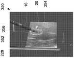
在使用标准超声成像来定位例如供治疗的纤维瘤并绘出其地图之后,引导系统可以用于帮助确定消融装置16的端头进入子宫的最佳位置。引导系统特征可以用作标准超声图像的附属物以帮助在程序期间定位消融装置16,并且显示消融装置16的端头将与超声平面352相交的位置。一旦消融装置16的端头穿透子宫浆膜,就可以使用超声可视化来完成将消融装置16定位在供治疗的子宫中的过程。After locating and mapping a fibroid for treatment, for example, using standard ultrasound imaging, a guidance system can be used to help determine the optimal position for the tip of the
图8A至图8D中示出了来自消融探针手机430和超声探针434、436或438的位置和取向信息可以如何由控制台422组合到综合GUI中的示例。集成的图像在界面490中展示,该界面示出了展示代表性超声换能器228和超声平面352以及代表性消融装置16的相对位置的三维(3D)视图的第一GUI 350。第二GUI 350’可以在超声换能器228和消融装置16定位在腹腔内时实时地显示它们的二维表示(例如,虚拟形象)。它将来自超声机的图像放置在虚拟超声换能器平面352上并且显示″目标区″,其中例如紫线作为消融装置16轴将与超声换能器平面352相交的位置的指示器。An example of how position and orientation information from
如图8A所示,位置线492可以显示在3D GUI 350上并且被提供作为代表性消融装置16相对于换能器平面352的预期轨迹的指示。如果该轨迹在超声平面352的″前面″,则轨迹的这个部分可以被示为第一颜色,例如示为黄线,而轨迹的位于超声平面352″后面″的部分可以用第二颜色表示,例如表示为蓝线。接近测量仪494也可以包括在界面490中,该接近测量仪位于例如GUI 350与350'之间,其中接近测量仪494可以示出消融装置16端头相对于超声平面352的位置。这在利用消融装置16的端头在超声的平面352内接近目标组织区域时可能是有帮助的。如果端头被示为在平面352的″前面″,则可以用第一颜色(例如,黄色)在接近测量仪494上显示条,但如果消融装置16的端头在平面352的″后面″,则可以用第二颜色(例如,蓝色)显示条。当消融装置16的端头与超声图像352位于″平面上″时,可以用第三颜色(例如,绿色)显示接近测量仪的条。As shown in FIG. 8A , a
图8B和图8C示出了界面490的另一示例,其中GUI 350、350'可以包括消融手机-超声″目标区″,其中软件可以提供对消融装置16的路径和该消融装置与超声平面352的预计相交点(目标区496)的预测,因此使用者可以在插入之前使消融装置16相对于目标纤维瘤取向。目标区496可以在GUI 350、350'两个视图中被示为叠加在超声扫描平面352上方的长圆形指示器。长圆形(由通过与两个半圆的端点成切线的平行线连接的这两个半圆形成的形状)的大小可以随着消融装置16相对于超声扫描平面352的角度而变,使得当消融装置16垂直于扫描平面352时,目标区496长圆形是圆,并且在角度朝向平行减小时,目标区496长圆形被示为在端部处以半圆加盖的两条线。消融装置16轨迹散列标记498可以在GUI 350、350’两个视图中显示。散列标记498可以在消融装置16轨迹远离超声扫描平面352时显示为例如红色和黄色标记,并且在消融装置16轨迹在超声平面352内时显示为例如绿色散列标记。FIGS. 8B and 8C illustrate another example of an
图8D示出了另一变型,其中GUI 350、350’可以被配置为示出在消融装置16的治疗部分结束时的预期消融体积的视觉指示器。预期的消融体积可以将预期的3D消融笼或治疗区500作为指示器显示给使用者,作为物理尺寸的3D视觉参考,以进一步帮助电极阵列放置,如下文进一步详细地描述。Figure 8D shows another variation in which the
图形用户界面的另外细节在2011年3月23日提交的两个美国专利申请13/069,472(美国公开2012/0245575)和13/069,497(美国公开2012/0245576);以及2014年11月10日提交的美国专利申请14/537,899(美国公开2015/0190206)中进一步详细地描述,这些专利申请中的每一者通过援引以其全文并出于任何目的引入本文。Additional details of the graphical user interface are in two US patent applications 13/069,472 (US Pub. 2012/0245575) and 13/069,497 (US Pub. 2012/0245576), filed March 23, 2011; and filed November 10, 2014 It is described in further detail in US Patent Application 14/537,899 (US Publication 2015/0190206), each of which is incorporated herein by reference in its entirety and for any purpose.
在使用期间,当从消融装置16部署管心针20时,管心针20的部署长度可以从部分延伸配置的任何长度调整到完全延伸配置。取决于从消融装置16部署的管心针20的长度,围绕管心针20的消融区的大小也将相应地改变。因此,使用者可以调整消融区的大小以与例如纤维瘤的大小匹配或相关,以及最小化对被治疗区域周围的组织区域的消融。During use, when the
为了便于确定治疗区域的大小,可以向使用者提供消融区的视觉表示,使得使用者不仅可以快速地确认消融装置16相对于治疗区的定位是足够的,而且确认管心针20的部署长度适合于产生足够大小的消融区。因此,可以提供基于指定的参数来自动地生成消融区的视觉表示的动态成像系统。To facilitate sizing of the treatment area, the user may be provided with a visual representation of the ablation area so that the user can quickly confirm not only that the positioning of the
示例在图9A至图9C的GUI 350中示出,这些图展示了视觉表示中的管心针20的部署和相应地确定大小消融区的图形表示。图9A示出了GUI 350的示例,展示表示超声探针228和当插入在供治疗的相关组织区域内时接近探针228的消融装置16的图像。Examples are shown in
可以致动超声探针228以提供组织区域的超声图像352,并且探针228可以围绕其纵向轴线旋转以调整可以在GUI 350上显示的图像352。如图10A所示,对应的计算机显示器220可以在单独的显示器上或在图9A所示的相同GUI 350上同时地呈现探针228的图像和超声图像352。The
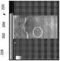
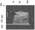
在探针228和消融装置16定位在待治疗的组织区域内或接近该组织区域定位的情况下,管心针20可以被推进通过对应的开口7以便部署到周围的组织区域中。在部署管心针20时,有效的消融可以根据部署的管心针20的长度而以对应的方式改变。因此,有效消融区的边界可以在GUI 350中被展示为三维边界或笼或治疗区354,以向使用者提供关于消融区在治疗期间将有多大的视觉指导,如图9B所示。在部署管心针20时,其部署位置或长度可以由系统(例如,处理器)跟踪,使得在任何时候都知道管心针20的部署长度。基于管心针20的已知长度,鉴于治疗温度是预先确定的,可以(例如,通过处理器)计算消融边界或笼或治疗区354以自动地确定大小。因此,使用者可以利用视觉边界或笼或治疗区354,以便利于相对于供治疗的相关组织区域来定位消融装置16。取决于有效消融区,边界或笼或治疗区354可以在视觉上呈现为椭圆形、卯形或球形形状。With
另外地,取决于从消融装置16的相应开口部署的管心针20的长度,边界或笼或治疗区354可以相应地改变其大小。示例在图9B与图9C之间示出,这些图展示了以第一配置(该第一配置是管心针20的部分部署长度)部署的管心针20及其对应的边界或笼354。如图9C所示,管心针20可以部署到第二配置,其中管心针20'具有完全部署长度,并且边界或笼或治疗区354'被示为具有在大小和体积方面比图9B所示的边界或笼或治疗区354相对更大的对应大小。因此,取决于从消融装置16部署的管心针20的长度,消融边界或笼或治疗区354可以在GUI 350中被表示为具有可以实时地改变的对应大小以便于治疗。Additionally, depending on the length of the
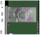
消融装置16可以与超声探针228结合使用,并且在探针228绕其纵向轴线旋转以调整图像352时,图像352与消融边界或笼或治疗区354之间的对应边界也可以在GUI 350中表示。图9B展示了图像352的平面与边界或笼或治疗区354之间的相交处356,并且系统可以将相交处356投射在显示器220上所显示的图像352上,如图10B中对应地示出。在部署管心针20'并且其对应的边界或笼或治疗区354’的大小在大小方面改变时,如图9C所指示,如在图像352中示出的投射的相交处356'也可以对应地改变其大小,如图10C所示。
由于探针228可以绕其纵向轴线旋转以调整图像352,因此图像352与消融边界或笼或治疗区354之间的对应边界也可以实时地改变。图11A至图11C展示了在图像352上显示的具有选定的部署长度的部署的管心针20及其对应的消融边界或笼或治疗区354的一个示例。在消融装置16维持在其位置的情况下,探针228可以绕其纵向轴线旋转,使得投射的图像352也扫掠或旋转。因此,图像352与边界或笼354之间的投射的相交处362可以实时地从初始相交处362变为如图11B所示的相交处362’、再变为如图11C所示的相交处362”。相交处362、362’、362”的对应图像可以在图12A至图12C的显示器370上示出,这些图像可以被使用者用作视觉确认以确保期望的治疗区域完全涵盖在消融区内。Since the
可以通过确定预设目标温度来确定图形地显示给使用者的消融边界或笼或治疗区354的大小,例如通过取得由管心针20提供的温度的平均值来计算该预设目标温度,该预设目标温度可以在GUI上显示为目标时间,如本文中先前描述。例如,对于由部署的管心针20提供的期望目标温度95℃,在表1中提供了关于代表性消融大小的消融设置,该表展示了在用于治疗的预定目标时间对于管心针20的给定部署长度的代表性消融大小中的预期消融区边界或笼或治疗区354,以便实现预期的目标治疗温度。The size of the ablation boundary or cage or
表1.代表性消融设置Table 1. Representative Ablation Settings


因此,对于给定的管心针部署长度,消融边界或笼可以通过以上示出的给定尺寸在GUI中展示。图13A至图13C展示了代表性图,示出对于在图13B中的消融边界或笼或治疗区380中以及在图13C的更完全部署的管心针20的对应更大消融边界或笼380’中的管心针20的给定部署长度D的代表性消融大小的长度L和宽度w。Thus, for a given stylet deployment length, the ablation boundary or cage can be presented in the GUI with the given dimensions shown above. Figures 13A-13C illustrate representative graphs showing corresponding larger ablation boundaries or
在另一变型中,如果管心针20中的一者或多者以意外的角度或意外的部署长度从消融装置中的相应开口离开,则系统可以生成预期的消融边界或笼的实时图像以向使用者展示在治疗期间实际消融区将是怎样。这可以用作检查以便使用者确定管心针是否适当地部署和定位。示例在图13D中示出,该展图示了具有以某一角度部署的一个或多个管心针20的消融装置16。消融边界或笼或治疗区382的对应图像可以被看作形成不均匀的形状,该形状可以向使用者指示一个或多个不当地部署的管心针。对于这个特定实施例,管心针中的每一个可以结合其自己的温度传感器以提供实时反馈来确定实际消融区的大小。In another variation, if one or more of the
本领域技术人员应理解,在不脱离上述实施例的宽泛发明构思的情况下,可以对上述实施例做出改变。因此,应理解,本发明不限于所披露的特定实施方案,而是意图涵盖如所附权利要求限定的本发明的精神和范围内的更改。Those skilled in the art will appreciate that changes may be made to the above-described embodiments without departing from the broad inventive concept of the above-described embodiments. Therefore, it is to be understood that this invention is not to be limited to the particular embodiments disclosed, but it is intended to cover modifications within the spirit and scope of this invention as defined by the appended claims.
Claims (36)
Priority Applications (1)
| Application Number | Priority Date | Filing Date | Title |
|---|---|---|---|
| CN202410280848.8ACN118216901A (en) | 2017-11-09 | 2018-11-09 | System for controlling ablation therapy and visualization |
Applications Claiming Priority (3)
| Application Number | Priority Date | Filing Date | Title |
|---|---|---|---|
| US201762583972P | 2017-11-09 | 2017-11-09 | |
| US62/583,972 | 2017-11-09 | ||
| PCT/US2018/060145WO2019094808A1 (en) | 2017-11-09 | 2018-11-09 | System for controlling ablation treatment and visualization |
Related Child Applications (1)
| Application Number | Title | Priority Date | Filing Date |
|---|---|---|---|
| CN202410280848.8ADivisionCN118216901A (en) | 2017-11-09 | 2018-11-09 | System for controlling ablation therapy and visualization |
Publications (2)
| Publication Number | Publication Date |
|---|---|
| CN111315294Atrue CN111315294A (en) | 2020-06-19 |
| CN111315294B CN111315294B (en) | 2024-03-19 |
Family
ID=66327982
Family Applications (2)
| Application Number | Title | Priority Date | Filing Date |
|---|---|---|---|
| CN202410280848.8APendingCN118216901A (en) | 2017-11-09 | 2018-11-09 | System for controlling ablation therapy and visualization |
| CN201880072306.4AActiveCN111315294B (en) | 2017-11-09 | 2018-11-09 | System for controlling ablation treatment and visualization |
Family Applications Before (1)
| Application Number | Title | Priority Date | Filing Date |
|---|---|---|---|
| CN202410280848.8APendingCN118216901A (en) | 2017-11-09 | 2018-11-09 | System for controlling ablation therapy and visualization |
Country Status (6)
| Country | Link |
|---|---|
| US (2) | US11648062B2 (en) |
| EP (2) | EP3706630B1 (en) |
| JP (1) | JP7291697B2 (en) |
| CN (2) | CN118216901A (en) |
| CA (1) | CA3077366A1 (en) |
| WO (1) | WO2019094808A1 (en) |
Cited By (5)
| Publication number | Priority date | Publication date | Assignee | Title |
|---|---|---|---|---|
| CN112185538A (en)* | 2020-10-14 | 2021-01-05 | 长春大学 | Blind person physiotherapy instrument system design method based on deep learning |
| CN113952021A (en)* | 2021-11-30 | 2022-01-21 | 北京阳光易帮医疗科技有限公司 | Refrigeration high-frequency energy system and control method thereof |
| CN113952031A (en)* | 2020-07-21 | 2022-01-21 | 巴德阿克塞斯系统股份有限公司 | Magnetic tracking ultrasound probe and system, method and apparatus for generating 3D visualization thereof |
| CN114942710A (en)* | 2020-12-31 | 2022-08-26 | 杭州堃博生物科技有限公司 | Ablation operation prompting method, electronic device and computer readable storage medium |
| WO2024031560A1 (en)* | 2022-08-11 | 2024-02-15 | 威朋(苏州)医疗器械有限公司 | Operation guiding and monitoring method and apparatus, and computer device |
Families Citing this family (10)
| Publication number | Priority date | Publication date | Assignee | Title |
|---|---|---|---|---|
| US8088072B2 (en) | 2007-10-12 | 2012-01-03 | Gynesonics, Inc. | Methods and systems for controlled deployment of needles in tissue |
| CN115715689B (en) | 2016-11-11 | 2025-01-17 | 杰尼索尼克斯公司 | Tissue controlled treatment and dynamic interaction and comparison with tissue and/or treatment data |
| US11648062B2 (en) | 2017-11-09 | 2023-05-16 | Acessa Health Inc. | System for controlling ablation treatment and visualization |
| EP3773232A1 (en)* | 2018-04-06 | 2021-02-17 | Medtronic, Inc. | Image-based navigation system and method of using same |
| WO2020176161A1 (en)* | 2019-02-25 | 2020-09-03 | Acessa Health Inc. | Automated ablation control systems |
| US20210298830A1 (en)* | 2020-03-25 | 2021-09-30 | Covidien Lp | Robotic surgical system and methods of use thereof |
| EP4252835A4 (en)* | 2020-11-30 | 2024-10-02 | Teijin Pharma Limited | PHOTOTHERAPEUTIC DEVICE |
| CN113171171B (en)* | 2021-04-29 | 2022-09-02 | 南京诺源医疗器械有限公司 | Multi-head microwave ablation needle and ablation simulation system establishment method |
| US20220354462A1 (en)* | 2021-05-10 | 2022-11-10 | Excera, Inc. | Multiscale ultrasound tracking and display |
| US12318252B2 (en)* | 2021-09-13 | 2025-06-03 | FemDx Medsystems, Inc. | Combined ultrasonic and direct visual hysteroscope |
Citations (8)
| Publication number | Priority date | Publication date | Assignee | Title |
|---|---|---|---|---|
| US5827276A (en)* | 1995-03-24 | 1998-10-27 | Board Of Regents Of Univ Of Nebraksa | Apparatus for volumetric tissue ablation |
| US20110137156A1 (en)* | 2009-02-17 | 2011-06-09 | Inneroptic Technology, Inc. | Systems, methods, apparatuses, and computer-readable media for image management in image-guided medical procedures |
| US20110230874A1 (en)* | 2005-07-01 | 2011-09-22 | Halt Medical Inc. | Ablation method |
| US8262574B2 (en)* | 2009-02-27 | 2012-09-11 | Gynesonics, Inc. | Needle and tine deployment mechanism |
| US20120245576A1 (en)* | 2011-03-23 | 2012-09-27 | Halt Medical Inc. | Merged image user interface and navigational tool for remote control of surgical devices |
| US20160095537A1 (en)* | 2014-10-04 | 2016-04-07 | Halt Medical Inc. | Surgical guidance system with low interference metal support structure |
| US20160128669A1 (en)* | 2014-11-06 | 2016-05-12 | Covidien Lp | System for tracking and imaging a treatment probe |
| CN106691580A (en)* | 2015-11-17 | 2017-05-24 | 柯惠有限合伙公司 | Systems and methods for ultrasound image-guided ablation antenna placement |
Family Cites Families (26)
| Publication number | Priority date | Publication date | Assignee | Title |
|---|---|---|---|---|
| US6241725B1 (en) | 1993-12-15 | 2001-06-05 | Sherwood Services Ag | High frequency thermal ablation of cancerous tumors and functional targets with image data assistance |
| US5538509A (en) | 1994-01-31 | 1996-07-23 | Richard-Allan Medical Industries, Inc. | Trocar assembly |
| US6142940A (en)* | 1998-10-06 | 2000-11-07 | Scimed Life Systems, Inc. | Control panel for intravascular ultrasonic imaging system |
| US6840935B2 (en) | 2000-08-09 | 2005-01-11 | Bekl Corporation | Gynecological ablation procedure and system using an ablation needle |
| US7678106B2 (en) | 2000-08-09 | 2010-03-16 | Halt Medical, Inc. | Gynecological ablation procedure and system |
| US6540685B1 (en)* | 2000-11-09 | 2003-04-01 | Koninklijke Philips Electronics N.V. | Ultrasound diagnostic device |
| US20060200121A1 (en) | 2005-03-03 | 2006-09-07 | Mowery Thomas M | Navigable, multi-positional and variable tissue ablation apparatus and methods |
| US8512333B2 (en) | 2005-07-01 | 2013-08-20 | Halt Medical Inc. | Anchored RF ablation device for the destruction of tissue masses |
| US8080009B2 (en) | 2005-07-01 | 2011-12-20 | Halt Medical Inc. | Radio frequency ablation device for the destruction of tissue masses |
| US9050123B2 (en)* | 2007-04-16 | 2015-06-09 | Smith & Nephew, Inc. | Powered surgical system |
| US8251991B2 (en) | 2007-11-14 | 2012-08-28 | Halt Medical Inc. | Anchored RF ablation device for the destruction of tissue masses |
| US8241276B2 (en) | 2007-11-14 | 2012-08-14 | Halt Medical Inc. | RF ablation device with jam-preventing electrical coupling member |
| US8781555B2 (en)* | 2007-11-26 | 2014-07-15 | C. R. Bard, Inc. | System for placement of a catheter including a signal-generating stylet |
| JP2009247434A (en)* | 2008-04-02 | 2009-10-29 | Olympus Medical Systems Corp | Surgery system |
| EP4122385A1 (en)* | 2010-05-28 | 2023-01-25 | C. R. Bard, Inc. | Insertion guidance system for needles and medical components |
| CN103140184B (en)* | 2010-09-29 | 2016-05-11 | 皇家飞利浦电子股份有限公司 | The temperature feedback system melting for adaptive RF |
| US20120245575A1 (en) | 2011-03-23 | 2012-09-27 | Halt Medical Inc. | User interface and navigational tool for remote control of an anchored rf ablation device for destruction of tissue masses |
| JP2015506209A (en) | 2011-12-28 | 2015-03-02 | ボストン サイエンティフィック サイムド,インコーポレイテッドBoston Scientific Scimed,Inc. | Ablation probe and ablation and ultrasound imaging system |
| US8670816B2 (en)* | 2012-01-30 | 2014-03-11 | Inneroptic Technology, Inc. | Multiple medical device guidance |
| US10667790B2 (en)* | 2012-03-26 | 2020-06-02 | Teratech Corporation | Tablet ultrasound system |
| US20140276052A1 (en)* | 2013-03-15 | 2014-09-18 | Philips Koninklijke Electronics N.V. | Ablation catheter with ultrasonic lesion monitoring capability |
| US10835203B2 (en) | 2013-11-11 | 2020-11-17 | Acessa Health Inc. | System for visualization and control of surgical devices utilizing a graphical user interface |
| US10278778B2 (en)* | 2016-10-27 | 2019-05-07 | Inneroptic Technology, Inc. | Medical device navigation using a virtual 3D space |
| KR20190086485A (en)* | 2016-11-14 | 2019-07-22 | 지네소닉스, 인크. | Methods and systems for real-time planning and monitoring of ablation needle deployment within an organization |
| US10786226B2 (en)* | 2017-02-09 | 2020-09-29 | Clarius Mobile Health Corp. | Ultrasound systems and methods for optimizing multiple imaging parameters using a single user interface control |
| US11648062B2 (en) | 2017-11-09 | 2023-05-16 | Acessa Health Inc. | System for controlling ablation treatment and visualization |
- 2018
- 2018-11-09USUS16/186,215patent/US11648062B2/enactiveActive
- 2018-11-09CNCN202410280848.8Apatent/CN118216901A/enactivePending
- 2018-11-09CNCN201880072306.4Apatent/CN111315294B/enactiveActive
- 2018-11-09EPEP18875276.0Apatent/EP3706630B1/enactiveActive
- 2018-11-09WOPCT/US2018/060145patent/WO2019094808A1/ennot_activeCeased
- 2018-11-09CACA3077366Apatent/CA3077366A1/enactivePending
- 2018-11-09JPJP2020525873Apatent/JP7291697B2/enactiveActive
- 2018-11-09EPEP23204767.0Apatent/EP4285852A3/ennot_activeWithdrawn
- 2023
- 2023-03-28USUS18/191,825patent/US20230233269A1/ennot_activeAbandoned
Patent Citations (8)
| Publication number | Priority date | Publication date | Assignee | Title |
|---|---|---|---|---|
| US5827276A (en)* | 1995-03-24 | 1998-10-27 | Board Of Regents Of Univ Of Nebraksa | Apparatus for volumetric tissue ablation |
| US20110230874A1 (en)* | 2005-07-01 | 2011-09-22 | Halt Medical Inc. | Ablation method |
| US20110137156A1 (en)* | 2009-02-17 | 2011-06-09 | Inneroptic Technology, Inc. | Systems, methods, apparatuses, and computer-readable media for image management in image-guided medical procedures |
| US8262574B2 (en)* | 2009-02-27 | 2012-09-11 | Gynesonics, Inc. | Needle and tine deployment mechanism |
| US20120245576A1 (en)* | 2011-03-23 | 2012-09-27 | Halt Medical Inc. | Merged image user interface and navigational tool for remote control of surgical devices |
| US20160095537A1 (en)* | 2014-10-04 | 2016-04-07 | Halt Medical Inc. | Surgical guidance system with low interference metal support structure |
| US20160128669A1 (en)* | 2014-11-06 | 2016-05-12 | Covidien Lp | System for tracking and imaging a treatment probe |
| CN106691580A (en)* | 2015-11-17 | 2017-05-24 | 柯惠有限合伙公司 | Systems and methods for ultrasound image-guided ablation antenna placement |
Cited By (6)
| Publication number | Priority date | Publication date | Assignee | Title |
|---|---|---|---|---|
| CN113952031A (en)* | 2020-07-21 | 2022-01-21 | 巴德阿克塞斯系统股份有限公司 | Magnetic tracking ultrasound probe and system, method and apparatus for generating 3D visualization thereof |
| CN112185538A (en)* | 2020-10-14 | 2021-01-05 | 长春大学 | Blind person physiotherapy instrument system design method based on deep learning |
| CN114942710A (en)* | 2020-12-31 | 2022-08-26 | 杭州堃博生物科技有限公司 | Ablation operation prompting method, electronic device and computer readable storage medium |
| CN113952021A (en)* | 2021-11-30 | 2022-01-21 | 北京阳光易帮医疗科技有限公司 | Refrigeration high-frequency energy system and control method thereof |
| CN113952021B (en)* | 2021-11-30 | 2024-01-26 | 北京阳光易帮医疗科技有限公司 | Freezing high-frequency energy system and control method thereof |
| WO2024031560A1 (en)* | 2022-08-11 | 2024-02-15 | 威朋(苏州)医疗器械有限公司 | Operation guiding and monitoring method and apparatus, and computer device |
Also Published As
| Publication number | Publication date |
|---|---|
| EP4285852A3 (en) | 2024-04-17 |
| EP4285852A2 (en) | 2023-12-06 |
| US11648062B2 (en) | 2023-05-16 |
| EP3706630B1 (en) | 2023-10-25 |
| EP3706630A1 (en) | 2020-09-16 |
| CA3077366A1 (en) | 2019-05-16 |
| JP7291697B2 (en) | 2023-06-15 |
| CN118216901A (en) | 2024-06-21 |
| CN111315294B (en) | 2024-03-19 |
| EP3706630A4 (en) | 2021-08-25 |
| US20190133696A1 (en) | 2019-05-09 |
| WO2019094808A1 (en) | 2019-05-16 |
| JP2021502168A (en) | 2021-01-28 |
| US20230233269A1 (en) | 2023-07-27 |
Similar Documents
| Publication | Publication Date | Title |
|---|---|---|
| CN111315294B (en) | System for controlling ablation treatment and visualization | |
| US20250114138A1 (en) | Merged image user interface and navigational tool for remote control of surgical devices | |
| EP1937176B1 (en) | Auxiliary image display and manipulation on a computer display in a medical robotic system | |
| EP3530221B1 (en) | System for performing a percutaneous navigation procedure | |
| KR101612278B1 (en) | Location system with virtual touch screen | |
| CN107997821B (en) | System and method for planning and navigating | |
| EP3537968B1 (en) | Systems for real-time planning and monitoring of ablation needle deployment in tissue | |
| US20240024023A1 (en) | Methods for monitoring ablation progress with doppler ultrasound | |
| WO2015186475A1 (en) | Medical treatment system | |
| CN115715174B (en) | Control scheme calibration of medical devices | |
| CN107530059A (en) | Microwave ablation plan and surgery systems | |
| US20120245575A1 (en) | User interface and navigational tool for remote control of an anchored rf ablation device for destruction of tissue masses | |
| US12053324B2 (en) | System for visualization and control of surgical devices utilizing a graphical user interface | |
| EP2688470B1 (en) | Merged image user interface and navigational tool for remote control of surgical devices | |
| CN116075276A (en) | Robot collision boundary determination | |
| US20250195154A1 (en) | User interface for surgical robotic system | |
| US20250195153A1 (en) | User interface for surgical robotic system | |
| EP4099932B1 (en) | Systems and methods for monitoring ablation antenna movement |
Legal Events
| Date | Code | Title | Description |
|---|---|---|---|
| PB01 | Publication | ||
| PB01 | Publication | ||
| SE01 | Entry into force of request for substantive examination | ||
| SE01 | Entry into force of request for substantive examination | ||
| GR01 | Patent grant | ||
| GR01 | Patent grant |