CN111307209A - Detection device for monitoring water leakage flow direction in underground water observation well - Google Patents
Detection device for monitoring water leakage flow direction in underground water observation wellDownload PDFInfo
- Publication number
- CN111307209A CN111307209ACN202010114999.8ACN202010114999ACN111307209ACN 111307209 ACN111307209 ACN 111307209ACN 202010114999 ACN202010114999 ACN 202010114999ACN 111307209 ACN111307209 ACN 111307209A
- Authority
- CN
- China
- Prior art keywords
- detection device
- optical fiber
- monitoring
- observation well
- optic fibre
- Prior art date
- Legal status (The legal status is an assumption and is not a legal conclusion. Google has not performed a legal analysis and makes no representation as to the accuracy of the status listed.)
- Pending
Links
- XLYOFNOQVPJJNP-UHFFFAOYSA-NwaterSubstancesOXLYOFNOQVPJJNP-UHFFFAOYSA-N0.000titleclaimsabstractdescription38
- 238000001514detection methodMethods0.000titleclaimsabstractdescription23
- 238000012544monitoring processMethods0.000titleclaimsabstractdescription22
- 239000013307optical fiberSubstances0.000claimsabstractdescription44
- 239000003673groundwaterSubstances0.000claimsabstractdescription25
- 230000003287optical effectEffects0.000claimsabstractdescription20
- 239000000835fiberSubstances0.000claimsdescription14
- 210000000689upper legAnatomy0.000claims1
- 239000002349well waterSubstances0.000claims1
- 235000020681well waterNutrition0.000claims1
- 238000000034methodMethods0.000description13
- 238000005259measurementMethods0.000description11
- 239000000700radioactive tracerSubstances0.000description7
- 239000000523sampleSubstances0.000description6
- 238000010586diagramMethods0.000description4
- 230000004913activationEffects0.000description2
- 230000008859changeEffects0.000description2
- 238000005516engineering processMethods0.000description2
- 239000000463materialSubstances0.000description2
- 238000012986modificationMethods0.000description2
- 230000004048modificationEffects0.000description2
- 230000008569processEffects0.000description2
- 238000005086pumpingMethods0.000description2
- 238000010998test methodMethods0.000description2
- 238000001069Raman spectroscopyMethods0.000description1
- 238000004458analytical methodMethods0.000description1
- 230000009286beneficial effectEffects0.000description1
- 238000006243chemical reactionMethods0.000description1
- 230000007547defectEffects0.000description1
- 238000013461designMethods0.000description1
- 238000005342ion exchangeMethods0.000description1
- 238000001556precipitationMethods0.000description1
- 238000002360preparation methodMethods0.000description1
- 238000012545processingMethods0.000description1
- 230000001681protective effectEffects0.000description1
- 239000000941radioactive substanceSubstances0.000description1
- 239000011435rockSubstances0.000description1
- 239000002689soilSubstances0.000description1
- 238000001179sorption measurementMethods0.000description1
- 238000012360testing methodMethods0.000description1
Images


Classifications
- G—PHYSICS
- G01—MEASURING; TESTING
- G01D—MEASURING NOT SPECIALLY ADAPTED FOR A SPECIFIC VARIABLE; ARRANGEMENTS FOR MEASURING TWO OR MORE VARIABLES NOT COVERED IN A SINGLE OTHER SUBCLASS; TARIFF METERING APPARATUS; MEASURING OR TESTING NOT OTHERWISE PROVIDED FOR
- G01D21/00—Measuring or testing not otherwise provided for
- G01D21/02—Measuring two or more variables by means not covered by a single other subclass
Landscapes
- Physics & Mathematics (AREA)
- General Physics & Mathematics (AREA)
- Geophysics And Detection Of Objects (AREA)
Abstract
Translated fromChinese
Description
Translated fromChinese技术领域technical field
本发明涉及一种用于地下水观测井内水渗漏流向监测的探测装置,属于水文地质参数监测技术领域。The invention relates to a detection device for monitoring the flow direction of water seepage in a groundwater observation well, belonging to the technical field of hydrogeological parameter monitoring.
背景技术Background technique
地下水监测井地下水的流动状况是了解水文地质情况的重要手段。目前,地下水流向的测得方法较多,传统方法主要分为抽水试验法和示踪法。传统的抽水试验法,不适用于单井监测,且耗时费力。示踪法又有放射性同位素示踪法、电位差法、热示踪法等。放射性同位素示踪法所需放射性物质,可能对人体及环境造成危害。示踪法所使用示踪剂可与地下水及岩土体发生离子交换、吸附、沉淀等理化反应,影响测量结果。而热示踪法对热敏元件的精度要求较高。另外还包括中子活化等技术,但中子活化的成本高且需采取防护措施。Groundwater monitoring well groundwater flow is an important means to understand the hydrogeological situation. At present, there are many methods for measuring groundwater flow, and the traditional methods are mainly divided into pumping test method and tracer method. The traditional pumping test method is not suitable for single well monitoring and is time-consuming and labor-intensive. The tracer method includes radioisotope tracer method, potential difference method, thermal tracer method, etc. The radioactive substances required by the radioisotope tracer method may cause harm to the human body and the environment. The tracer used in the tracer method can undergo physical and chemical reactions such as ion exchange, adsorption, and precipitation with groundwater and rock and soil, which affect the measurement results. The thermal tracing method has higher requirements on the precision of the thermal element. In addition, technologies such as neutron activation are also included, but neutron activation is costly and requires protective measures.
现有技术中虽然出现探头测量地下水流向,但是现有的普通探头使用水深较浅,且仅能探测基本水质信息,实用性不是很强。另外,普通探头易受周围电磁环境的干扰,准确度不是很高。Although there are probes in the prior art to measure the flow direction of groundwater, the existing common probes use shallow water depths and can only detect basic water quality information, so their practicability is not very strong. In addition, ordinary probes are easily interfered by the surrounding electromagnetic environment, and the accuracy is not very high.
发明内容SUMMARY OF THE INVENTION
本发明要解决的技术问题是,克服现有技术的缺陷,提供一种使用水深较深、不受周围电磁环境的干扰和能够准确地确定探测区的水流方向和水温等数据的用于地下水观测井内水渗漏流向监测的探测装置。The technical problem to be solved by the present invention is to overcome the defects of the prior art and provide a groundwater observation device that uses data such as deep water depth, is not disturbed by the surrounding electromagnetic environment, and can accurately determine the water flow direction and water temperature in the detection area. A detection device for monitoring the flow of water seepage in a well.
为解决上述技术问题,本发明采用的技术方案为:In order to solve the above-mentioned technical problems, the technical scheme adopted in the present invention is:
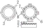
一种用于地下水观测井内水渗漏流向监测的探测装置,包括偶数股呈环形设置的光纤,所述光纤上设置有固定圈,所述固定圈包括相连内圈和外圈,所述光纤位于所述内圈和外圈之间,所述光纤的下端设置有光路闭合器,所述光路闭合器内设置有U形光纤,所述U形光纤将相邻的两个所述光纤末端连接形成闭合回路,所述光纤的前端设置有光纤耦合器,所述光纤耦合器的前端设置有电子罗盘,所述电子罗盘的前端通过光缆连有地面数据处理器。A detection device for monitoring the flow direction of water leakage in a groundwater observation well, comprising an even-numbered optical fiber arranged in a ring shape, the optical fiber is provided with a fixed ring, the fixed ring includes a connected inner ring and an outer ring, and the optical fiber is located in the Between the inner ring and the outer ring, the lower end of the optical fiber is provided with an optical path closure, and a U-shaped optical fiber is arranged in the optical path closure, and the U-shaped optical fiber connects the ends of two adjacent optical fibers to form A closed loop, the front end of the optical fiber is provided with an optical fiber coupler, the front end of the optical fiber coupler is provided with an electronic compass, and the front end of the electronic compass is connected with a ground data processor through an optical cable.
所述固定圈的个数为3个。The number of the fixed rings is three.
所述光路闭合器底部设置有配重物。The bottom of the optical path closer is provided with a counterweight.
所述光纤的股数为28股。The number of strands of the optical fiber is 28 strands.
所述外圈上设置有连接接口,最末端的所述固定圈上的所述连接接口与所述光路闭合器连接。The outer ring is provided with a connection interface, and the connection interface on the fixed ring at the end is connected with the optical path closer.
两个相邻的所述固定圈连接在一起。Two adjacent said retaining rings are connected together.
本发明的有益效果:本发明提供的一种用于地下水观测井内水渗漏流向监测的探测装置,装置实现流向流速探测,不必进行一一进行单点监测,可以一次性对沿线数十米的水况进行监测,。同时,该装置设计一体化,其操作简单、携带方便,无需繁琐的人力物力支撑,解决了普通探头仅能探测基本水质信息的缺点,便于准确地确定探测区的水流方向和水温等数据;二、解决了普通探头使用水深较潜的问题;三、光纤测量不易受周围电磁环境的干扰,比普通探头更为精准稳定;四、使用者可根据自身的需要,更换内部光纤布置数量,提高精度;五、装置结构简单,操作简便,能够折叠,方便携带。Beneficial effects of the present invention: The present invention provides a detection device for monitoring the flow direction of water seepage in a groundwater observation well. The device realizes the detection of the flow direction and flow rate, and it is not necessary to carry out single-point monitoring one by one. Water conditions are monitored. At the same time, the design of the device is integrated, it is simple to operate, easy to carry, and does not require tedious manpower and material support, which solves the shortcoming that ordinary probes can only detect basic water quality information, and facilitates accurate determination of the water flow direction and water temperature in the detection area. , Solve the problem that the depth of water used by ordinary probes is relatively deep; 3. Optical fiber measurement is less susceptible to the interference of the surrounding electromagnetic environment, and is more accurate and stable than ordinary probes; 4. Users can change the number of internal optical fiber arrangements according to their own needs to improve accuracy. ; 5. The device is simple in structure, easy to operate, foldable and easy to carry.
附图说明Description of drawings
图1为本发明一种用于地下水观测井内水渗漏流向监测的探测装置的整体结构示意图;1 is a schematic diagram of the overall structure of a detection device for monitoring the flow direction of water seepage in a groundwater observation well according to the present invention;
图2为本发明一种用于地下水观测井内水渗漏流向监测的探测装置的截面结构示意图;2 is a schematic cross-sectional structure diagram of a detection device for monitoring the flow direction of water seepage in a groundwater observation well according to the present invention;
图3为本发明一种用于地下水观测井内水渗漏流向监测的探测装置(两个固定圈相连)的结构示意图;3 is a schematic structural diagram of a detection device (two fixed rings are connected) for monitoring the flow direction of water seepage in a groundwater observation well according to the present invention;
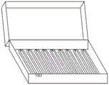
图4为本发明一种用于地下水观测井内水渗漏流向监测的探测装置的收纳结构示意图。4 is a schematic diagram of the storage structure of a detection device used for monitoring the flow direction of water leakage in a groundwater observation well according to the present invention.
图中附图标记如下:1-光缆、2-光纤、3-固定圈、4-光纤耦合器、5-地面数据处理器、6-光路闭合器、7-U形光纤、8-连接接口、9-电子罗盘。The reference numerals in the figure are as follows: 1-optical cable, 2-optical fiber, 3-fixed ring, 4-optical fiber coupler, 5-ground data processor, 6-optical path closer, 7-U-shaped fiber, 8-connection interface, 9- Electronic compass.
具体实施方式Detailed ways
下面结合附图对本发明作进一步描述,以下实施例仅用于更加清楚地说明本发明的技术方案,而不能以此来限制本发明的保护范围。The present invention will be further described below with reference to the accompanying drawings. The following embodiments are only used to more clearly illustrate the technical solutions of the present invention, and cannot be used to limit the protection scope of the present invention.
如图1和图2所示,本发明提供一种用于地下水观测井内水渗漏流向监测的探测装置,包括偶数股呈环形设置的光纤2,光纤共有数十股,数量为偶数,具体数量由使用者需要的测量精度决定,光纤2的股数为28股。光纤2成圆形排列,并固定于3固定圈上,固定圈3的个数优选为3个。固定圈3包括相连内圈和外圈,光纤2位于内圈和外圈之间,固定圈3圈体侧有连接接口8用于连接光路闭合器6。如图3所示,也可将两个固定圈3相连,增加测量段以扩大测量深度。光路闭合器6设置在光纤2的下端,光路闭合器6应与最末端的固定圈3用连接接口8扣住相连接,使每两股临近的光纤2形成闭合光路,在光路闭合器6进行配重,光路闭合器6底部设置有配重物,使装置在水中尽可能保持稳定。As shown in Figures 1 and 2, the present invention provides a detection device for monitoring the flow direction of water seepage in a groundwater observation well, comprising an even number of
光路闭合器6内设置有U形光纤7,U形光纤7将相邻的两个光纤2末端连接形成闭合回路。光纤2的前端设置有光纤耦合器4,光纤耦合器4用于光纤2的合路与分路。光纤耦合器4的前端设置有电子罗盘9,电子罗盘9用于判定水流流向。电子罗盘9的前端通过光缆1连有地面数据处理器5。地面数据处理器5用于处理光信息,使其转换为需要的数据。光缆1用于传输光数据,不用于监测数据,光缆1长度由地下水位决定,具体长度由使用者判断。A U-shaped
如图4所示,本发明的装置能够呈S型装入箱中,本装置直径小,可进行曲率半径较小的弯曲,对储藏空间的利用率高,方便携带。As shown in FIG. 4 , the device of the present invention can be put into a box in an S shape. The device has a small diameter, can be bent with a small radius of curvature, has high utilization rate of storage space, and is convenient to carry.
本发明的工作过程为:The working process of the present invention is:
步骤一、测量前的准备工作。安装装置各个部件,如附图1和2所示。测量之前确保各个部件安装到位,先对待测地下水的埋藏深度进行测量,确认需要测量的深度,以决定是否需要增加光纤段(附图3),检查无误之后可以进行测量。Step 1. Preparation before measurement. Install the various components of the device as shown in Figures 1 and 2. Before measurement, ensure that all components are installed in place, first measure the buried depth of the groundwater to be measured, and confirm the depth to be measured to determine whether to add fiber segments (Figure 3). After checking, the measurement can be carried out.
步骤二、数据测量。将装有本探测装置的光缆放入井内,直到所有测量光纤没入水中。此时光纤最顶端测得的为地下水水面处的数据,最下端所处的深度由测试人员使用的光纤段的长度决定,需防止底部触碰到地下水底面而导致光纤段弯曲,造成的较大数据误差。Step 2: Data measurement. Put the fiber optic cable equipped with this detection device into the well until all the measuring fibers are submerged in the water. At this time, the data measured at the top of the optical fiber is the data at the groundwater surface, and the depth of the bottom end is determined by the length of the optical fiber segment used by the tester. data error.
步骤三,渗漏测。将本装置没入水中后,装置保持静止,以提高数据的准确性。本装置基于光纤传感技术进行工作和数据测量,光纤沿线某点受到水流冲击时,光纤发生应变,地面数据处理器通过测得的其频移数据处理测得其应变。本装置内的光线呈环形排列,横截面应变分布上产生应变最大的点对应的方向即为渗漏点所处的方位,竖截面上的应力分布则代表着渗漏的竖向范围。其中,涉及到的应变公式为:Vb(t)=Vbo(1-αt)The third step is leak testing. After the device is submerged in water, the device remains stationary to improve the accuracy of the data. The device performs work and data measurement based on optical fiber sensing technology. When a certain point along the optical fiber is impacted by water flow, the optical fiber is strained, and the ground data processor measures the strain by processing the measured frequency shift data. The light in the device is arranged in a ring, the direction corresponding to the point with the largest strain on the cross-sectional strain distribution is the orientation of the leakage point, and the stress distribution on the vertical section represents the vertical range of the leakage. Among them, the strain formula involved is: Vb(t)=Vbo(1-αt)
其中G为应力比例系数,Vb(t)为应变t时的频移,Vbo为无应变时的频移,频移与所采用的的材料有关,α为常数。Where G is the stress proportional coefficient, Vb(t) is the frequency shift when strain t, Vbo is the frequency shift when no strain, the frequency shift is related to the material used, and α is a constant.
当有渗流水流过时,温度将发生变化,由地面数据处理器经过处理得到温度数据也可以作为判断水流方向的依据。综合分析应变和温度数据可得到更准确的流向结论。温度数据由斯托克斯光与反斯托克斯光光子数比值而得,其公式为:When seepage water flows, the temperature will change, and the temperature data obtained by the ground data processor can also be used as the basis for judging the direction of the water flow. Comprehensive analysis of strain and temperature data can lead to more accurate flow direction conclusions. The temperature data is obtained from the ratio of the number of photons of Stokes light to anti-Stokes light, and the formula is:
T=hΔf{ln(Is/Ias)+4ln[(f0+Δf)/(f0-Δf)]-1}/kT=hΔf{ln(Is/Ias)+4ln[(f0 +Δf)/(f0 -Δf)]-1 }/k
其中h为普朗克常数,K为波尔兹曼常数,Is为斯托克斯光强,Ias为反斯托克斯光强,f0为伴随光频率,△f为拉曼光频率增加量。where h is Planck's constant, K is Boltzmann's constant, Is is Stokes light intensity, Ias is anti-Stokes light intensity, f0 is the accompanying light frequency, and Δf is the Raman light frequency increase quantity.
最后,方向数据将由电子罗盘提供。Finally, orientation data will be provided by an electronic compass.
步骤四,测量结束后,将装置从井内取出,将装置呈S型装入箱中,本装置直径小,可进行曲率半径较小的弯曲,对储藏空间的利用率高,方便携带。Step 4: After the measurement, take the device out of the well and put the device into the box in an S shape. The device has a small diameter and can be bent with a small radius of curvature. It has high utilization of storage space and is easy to carry.
以上所述仅是本发明的优选实施方式,应当指出:对于本技术领域的普通技术人员来说,在不脱离本发明原理的前提下,还可以做出若干改进和润饰,这些改进和润饰也应视为本发明的保护范围。The above is only the preferred embodiment of the present invention, it should be pointed out that: for those skilled in the art, without departing from the principle of the present invention, several improvements and modifications can also be made, and these improvements and modifications are also It should be regarded as the protection scope of the present invention.
Claims (6)
Priority Applications (1)
| Application Number | Priority Date | Filing Date | Title |
|---|---|---|---|
| CN202010114999.8ACN111307209A (en) | 2020-02-25 | 2020-02-25 | Detection device for monitoring water leakage flow direction in underground water observation well |
Applications Claiming Priority (1)
| Application Number | Priority Date | Filing Date | Title |
|---|---|---|---|
| CN202010114999.8ACN111307209A (en) | 2020-02-25 | 2020-02-25 | Detection device for monitoring water leakage flow direction in underground water observation well |
Publications (1)
| Publication Number | Publication Date |
|---|---|
| CN111307209Atrue CN111307209A (en) | 2020-06-19 |
Family
ID=71149178
Family Applications (1)
| Application Number | Title | Priority Date | Filing Date |
|---|---|---|---|
| CN202010114999.8APendingCN111307209A (en) | 2020-02-25 | 2020-02-25 | Detection device for monitoring water leakage flow direction in underground water observation well |
Country Status (1)
| Country | Link |
|---|---|
| CN (1) | CN111307209A (en) |
Citations (9)
| Publication number | Priority date | Publication date | Assignee | Title |
|---|---|---|---|---|
| US20030155111A1 (en)* | 2001-04-24 | 2003-08-21 | Shell Oil Co | In situ thermal processing of a tar sands formation |
| US20030205378A1 (en)* | 2001-10-24 | 2003-11-06 | Wellington Scott Lee | In situ recovery from lean and rich zones in a hydrocarbon containing formation |
| CN105300554A (en)* | 2015-09-14 | 2016-02-03 | 中国人民解放军国防科学技术大学 | Multifunctional marine environment monitoring device based on distributed optical fiber sensing and method |
| CN105486351A (en)* | 2016-01-14 | 2016-04-13 | 中国地质大学(武汉) | Real-time monitoring method and real-time monitoring system for velocity and direction of underground water current |
| CN207866303U (en)* | 2018-03-09 | 2018-09-14 | 中国长江电力股份有限公司 | A kind of fiber F-P many reference amounts Intelligent Flowing Sensor |
| CN109898993A (en)* | 2019-03-29 | 2019-06-18 | 长江勘测规划设计研究有限责任公司 | The measurement device of groundwater velocity and direction in vertical drilling |
| CN109959802A (en)* | 2019-03-14 | 2019-07-02 | 山东大学 | An underwater detector, groundwater velocity and flow direction measuring instrument and method |
| CN110108668A (en)* | 2019-05-14 | 2019-08-09 | 东北大学 | A kind of U-shaped optical fiber LSPR sensor based on silver-colored set square |
| CN110672877A (en)* | 2019-10-24 | 2020-01-10 | 北京欧仕科技有限公司 | Underground water flow direction and flow velocity monitoring device and method |
- 2020
- 2020-02-25CNCN202010114999.8Apatent/CN111307209A/enactivePending
Patent Citations (9)
| Publication number | Priority date | Publication date | Assignee | Title |
|---|---|---|---|---|
| US20030155111A1 (en)* | 2001-04-24 | 2003-08-21 | Shell Oil Co | In situ thermal processing of a tar sands formation |
| US20030205378A1 (en)* | 2001-10-24 | 2003-11-06 | Wellington Scott Lee | In situ recovery from lean and rich zones in a hydrocarbon containing formation |
| CN105300554A (en)* | 2015-09-14 | 2016-02-03 | 中国人民解放军国防科学技术大学 | Multifunctional marine environment monitoring device based on distributed optical fiber sensing and method |
| CN105486351A (en)* | 2016-01-14 | 2016-04-13 | 中国地质大学(武汉) | Real-time monitoring method and real-time monitoring system for velocity and direction of underground water current |
| CN207866303U (en)* | 2018-03-09 | 2018-09-14 | 中国长江电力股份有限公司 | A kind of fiber F-P many reference amounts Intelligent Flowing Sensor |
| CN109959802A (en)* | 2019-03-14 | 2019-07-02 | 山东大学 | An underwater detector, groundwater velocity and flow direction measuring instrument and method |
| CN109898993A (en)* | 2019-03-29 | 2019-06-18 | 长江勘测规划设计研究有限责任公司 | The measurement device of groundwater velocity and direction in vertical drilling |
| CN110108668A (en)* | 2019-05-14 | 2019-08-09 | 东北大学 | A kind of U-shaped optical fiber LSPR sensor based on silver-colored set square |
| CN110672877A (en)* | 2019-10-24 | 2020-01-10 | 北京欧仕科技有限公司 | Underground water flow direction and flow velocity monitoring device and method |
Non-Patent Citations (1)
| Title |
|---|
| 黄宏伟: "《隧道结构非接触式快速检测与健康评估》", 31 December 2018* |
Similar Documents
| Publication | Publication Date | Title |
|---|---|---|
| US20120229623A1 (en) | Pendulum-type landslide monitoring system | |
| CN106121635B (en) | Distributed temperature test macro and method for hot dry rock deep-well | |
| CN113513302B (en) | Underground fluid monitoring system and method based on distributed optical fiber hydrophone | |
| CN111457889B (en) | Method for monitoring subway tunnel settlement through optical fiber static level | |
| CN106846736A (en) | A kind of sensing system of landslide Geological Hazards Monitoring | |
| CN112031743B (en) | Underground fluid identification device and measurement method based on distributed optical fiber sensing technology | |
| CN105783866B (en) | A kind of tank gage and sedimentation monitoring system based on low coherence interference technology | |
| CN201915944U (en) | Oil well liquid level testing device | |
| CN105157999A (en) | Method for assessing pile integrity and lateral displacement based on distributed optical fiber sensing technology | |
| CN102155628A (en) | Underground drainage pipeline leakage detection method and device | |
| CN110596182A (en) | Geomembrane Damage Leakage Monitoring System and Monitoring Method Based on Distributed Optical Fiber | |
| CN102031960A (en) | Oil well liquid level testing method and device | |
| Wang et al. | A synchronous and accurate detection method for gas pipeline leakage position and flow rate based on double fiber Bragg gratings | |
| CN108592813A (en) | A kind of Excavation Deformation of Deep Foundation Pits real-time monitoring device | |
| CN107830890A (en) | A kind of tunnel safety monitoring system based on fibre optical sensor | |
| CN204286374U (en) | A kind of hydro-structure distortion distributed optical fiber sensing device | |
| CN111307209A (en) | Detection device for monitoring water leakage flow direction in underground water observation well | |
| CN111638384B (en) | An optical fiber detection device for monitoring the flow velocity of groundwater in an observation well | |
| Zheng et al. | Investigation of a quasi-distributed displacement sensor using the macro-bending loss of an optical fiber | |
| CN111395297A (en) | CPTU device applying optical fiber technology in shallow sea geology | |
| CN212250002U (en) | Downhole fluid identification device based on distributed optical fiber sensing technology | |
| CN203083529U (en) | Brillouin optical sensing type continuous multi-point displacement meter measurement apparatus | |
| CN213956272U (en) | Rock-soil body deformation monitoring device based on distributed optical fiber | |
| CN105572329B (en) | Concrete crack scale distance adaptive monitoring method | |
| CN112114162B (en) | Hydrology observation well water flow direction detection device |
Legal Events
| Date | Code | Title | Description |
|---|---|---|---|
| PB01 | Publication | ||
| PB01 | Publication | ||
| SE01 | Entry into force of request for substantive examination | ||
| SE01 | Entry into force of request for substantive examination | ||
| RJ01 | Rejection of invention patent application after publication | ||
| RJ01 | Rejection of invention patent application after publication | Application publication date:20200619 |