CN111300377A - Lower limb wearing enhanced exoskeleton robot based on steel wire driving - Google Patents
Lower limb wearing enhanced exoskeleton robot based on steel wire drivingDownload PDFInfo
- Publication number
- CN111300377A CN111300377ACN201811507269.3ACN201811507269ACN111300377ACN 111300377 ACN111300377 ACN 111300377ACN 201811507269 ACN201811507269 ACN 201811507269ACN 111300377 ACN111300377 ACN 111300377A
- Authority
- CN
- China
- Prior art keywords
- hip joint
- joint
- knee joint
- pulley
- hip
- Prior art date
- Legal status (The legal status is an assumption and is not a legal conclusion. Google has not performed a legal analysis and makes no representation as to the accuracy of the status listed.)
- Pending
Links
- 210000003141lower extremityAnatomy0.000titleclaimsabstractdescription23
- 229910000831SteelInorganic materials0.000titleclaimsabstractdescription19
- 239000010959steelSubstances0.000titleclaimsabstractdescription19
- 210000004394hip jointAnatomy0.000claimsabstractdescription117
- 210000000629knee jointAnatomy0.000claimsabstractdescription95
- 210000003049pelvic boneAnatomy0.000claimsdescription32
- 210000003423ankleAnatomy0.000claimsdescription24
- 210000000544articulatio talocruralisAnatomy0.000claimsdescription14
- 210000004197pelvisAnatomy0.000claimsdescription13
- 244000309466calfSpecies0.000claimsdescription11
- 239000012636effectorSubstances0.000claimsdescription7
- 238000005452bendingMethods0.000claimsdescription6
- 238000005096rolling processMethods0.000claimsdescription6
- 230000003190augmentative effectEffects0.000claimsdescription3
- 210000001624hipAnatomy0.000claimsdescription2
- 230000033001locomotionEffects0.000abstractdescription17
- 210000002414legAnatomy0.000abstractdescription15
- 230000005540biological transmissionEffects0.000abstractdescription6
- 238000005516engineering processMethods0.000abstractdescription6
- 238000000034methodMethods0.000abstractdescription6
- 230000000694effectsEffects0.000abstractdescription3
- 210000001503jointAnatomy0.000description6
- 238000010586diagramMethods0.000description5
- 210000002683footAnatomy0.000description2
- 230000001360synchronised effectEffects0.000description2
- 208000029549Muscle injuryDiseases0.000description1
- 230000003321amplificationEffects0.000description1
- 230000009286beneficial effectEffects0.000description1
- 210000000988bone and boneAnatomy0.000description1
- 210000000845cartilageAnatomy0.000description1
- 239000003638chemical reducing agentSubstances0.000description1
- 230000003203everyday effectEffects0.000description1
- 238000009776industrial productionMethods0.000description1
- 230000007774longtermEffects0.000description1
- 238000012986modificationMethods0.000description1
- 230000004048modificationEffects0.000description1
- 238000003199nucleic acid amplification methodMethods0.000description1
- 210000000689upper legAnatomy0.000description1
Images


Classifications
- B—PERFORMING OPERATIONS; TRANSPORTING
- B25—HAND TOOLS; PORTABLE POWER-DRIVEN TOOLS; MANIPULATORS
- B25J—MANIPULATORS; CHAMBERS PROVIDED WITH MANIPULATION DEVICES
- B25J9/00—Programme-controlled manipulators
- B—PERFORMING OPERATIONS; TRANSPORTING
- B25—HAND TOOLS; PORTABLE POWER-DRIVEN TOOLS; MANIPULATORS
- B25J—MANIPULATORS; CHAMBERS PROVIDED WITH MANIPULATION DEVICES
- B25J17/00—Joints
- B—PERFORMING OPERATIONS; TRANSPORTING
- B25—HAND TOOLS; PORTABLE POWER-DRIVEN TOOLS; MANIPULATORS
- B25J—MANIPULATORS; CHAMBERS PROVIDED WITH MANIPULATION DEVICES
- B25J17/00—Joints
- B25J17/02—Wrist joints
- B—PERFORMING OPERATIONS; TRANSPORTING
- B25—HAND TOOLS; PORTABLE POWER-DRIVEN TOOLS; MANIPULATORS
- B25J—MANIPULATORS; CHAMBERS PROVIDED WITH MANIPULATION DEVICES
- B25J9/00—Programme-controlled manipulators
- B25J9/0006—Exoskeletons, i.e. resembling a human figure
- B—PERFORMING OPERATIONS; TRANSPORTING
- B25—HAND TOOLS; PORTABLE POWER-DRIVEN TOOLS; MANIPULATORS
- B25J—MANIPULATORS; CHAMBERS PROVIDED WITH MANIPULATION DEVICES
- B25J9/00—Programme-controlled manipulators
- B25J9/0009—Constructional details, e.g. manipulator supports, bases
Landscapes
- Engineering & Computer Science (AREA)
- Robotics (AREA)
- Mechanical Engineering (AREA)
- Manipulator (AREA)
- Rehabilitation Tools (AREA)
Abstract
Description
Translated fromChinese技术领域technical field
本发明涉及工业自动化技术领域,本发明涉及一种基于钢丝驱动下肢穿戴增强型外骨骼机器人。The invention relates to the technical field of industrial automation, and relates to an enhanced exoskeleton robot based on wire-driven lower limb wear.
背景技术Background technique
在现如今的工业生产作业中,许多工人每天需要使用重型的工具或者物流行业中对一些物品进行搬运操作,弯腰操作等,长时间的重复和高强度的运动会导致工人疲劳,肌肉损伤等一系列安全和效率问题,目前同类企业一般采用伺服电机关节直接驱动的方法来完成外骨骼的设计,电机和减速器直接组合安装在关节处,导致腿部的外骨骼无法贴合使用者,结构厚度较大,运动偏转惯量很大,无法很好的实现力跟随和助力放大,影响外骨骼的运动性能,同时宽大的结构件导致使用者的体积增大,无法在狭小的空间内操作,无法进入常规的建筑物和工业环境。外骨骼的灵活性较差,另有一些产品采用气动动力设计,这样的设备需要压缩机提供起源,设备噪音较大,而且压缩机体积巨大,移动能力有限,较大的限制了外骨骼的机动性,气动系统的操作精度较低,管路布局较为宽松,不紧凑,空间占用体积较大,影响外骨骼的穿戴效果。In today's industrial production operations, many workers need to use heavy-duty tools every day or in the logistics industry to carry some items, bend over, etc. Long-term repetition and high-intensity exercise will lead to worker fatigue, muscle damage, etc. There are a series of safety and efficiency issues. At present, similar companies generally use the direct drive method of servo motor joints to complete the design of exoskeletons. The motor and reducer are directly combined and installed at the joints, resulting in the exoskeleton of the legs being unable to fit the user, and the thickness of the structure Large, the motion deflection inertia is very large, which cannot well achieve force following and boosting amplification, which affects the movement performance of the exoskeleton. At the same time, the large structural parts cause the user's volume to increase, making it impossible to operate in a narrow space and to enter Regular buildings and industrial environments. The flexibility of the exoskeleton is poor, and some products are designed with aerodynamic power. Such equipment requires a compressor to provide the source, the equipment is noisy, and the compressor is large and has limited mobility, which greatly limits the mobility of the exoskeleton. The operation accuracy of the pneumatic system is low, the pipeline layout is relatively loose and not compact, and the space occupied is large, which affects the wearing effect of the exoskeleton.
发明内容SUMMARY OF THE INVENTION
本发明的目的就在于为了解决上述问题而提供一种基于钢丝驱动下肢穿戴增强型外骨骼机器人。The purpose of the present invention is to provide an enhanced exoskeleton robot based on wire-driven lower limb wear in order to solve the above problems.
本发明通过以下技术方案来实现上述目的:The present invention realizes above-mentioned purpose through following technical scheme:
一种基于钢丝驱动下肢穿戴增强型外骨骼机器人,包括背板基座、电池、髋关节驱动器和膝关节驱动器,所述背板基座一侧设置有电池,所述电池下方设置有所述髋关节驱动器,所述髋关节驱动器一侧设置有所述膝关节驱动器,所述髋关节驱动器下方设置有髋关节绝对位置单元,所述膝关节驱动器下方设置有膝关节绝对位置单元,所述背板基座下方设置有盆骨调整基座,所述盆骨调整基座下方设置有盆骨宽度调节锁定把手,所述盆骨宽度调节锁定把手下方设置有盆骨软包,所述髋关节驱动器和所述膝关节驱动器两侧均设置有转向滑轮一,所述转向滑轮一一侧设置有转向滑轮二,所述转向滑轮一之间设置有髋关节钢丝驱动链,所述转向滑轮二之间设置有钢丝转向结构件,所述转向滑轮二一侧设置有外侧滑轮二,所述外侧滑轮二一侧设置有髋关节外展内收转轴,所述外侧滑轮二下方设置有外侧滑轮一,所述外侧滑轮一一侧设置有髋关节屈伸伸展转轴,所述髋关节屈伸伸展转轴外围设置有膝关节驱动转向滑轮,所述膝关节驱动转向滑轮一侧设置有髋关节驱动定滑轮,所述髋关节驱动定滑轮一侧设置有髋关节外展内收结构,所述膝关节驱动转向滑轮上设置有膝关节驱动钢丝,所述膝关节驱动转向滑轮另一侧设置有髋关节,所述髋关节上设置有固定绑带二,所述固定绑带二上设置有髋关节力传感器,所述髋关节下端设置有膝关节,所述膝关节与所述髋关节之间设置有膝关节转轴,所述膝关节下方设置有小腿,所述小腿上设置有固定绑带一,所述固定绑带一上设置有膝关节力传感器,所述小腿侧壁上设置有膝关节定滑轮,所述膝关节定滑轮下方设置有脚踝固定器,所述脚踝固定器与所述小腿之间设置有踝关节弯曲伸展转轴,所述踝关节弯曲伸展转轴下方设置有踝关节内外翻转轴,所述脚踝固定器下方设置有足底效应器。An augmented exoskeleton robot based on wire-driven lower limb wear, comprising a backboard base, a battery, a hip joint driver and a knee joint driver, a battery is arranged on one side of the backboard base, and the hip joint is arranged below the battery A joint driver, the knee joint driver is arranged on one side of the hip joint driver, a hip joint absolute position unit is arranged below the hip joint driver, a knee joint absolute position unit is arranged below the knee joint driver, and the back plate A pelvic bone adjustment base is arranged under the base, a pelvic bone width adjustment locking handle is arranged under the pelvic bone adjustment base, a pelvic bone soft bag is arranged under the pelvic bone width adjustment locking handle, and the hip joint driver and Both sides of the knee joint driver are provided with a steering pulley 1, one side of the steering pulley is provided with a
进一步的,所述髋关节驱动器以及所述膝关节驱动器与所述背板基座均通过螺钉连接,所述髋关节驱动器的型号为SRS-545SH,所述膝关节驱动器的型号为SRS-545SH。Further, the hip joint driver and the knee joint driver are connected with the backplane base by screws, and the model of the hip joint driver is SRS-545SH, and the model of the knee joint driver is SRS-545SH.
进一步的,所述电池与所述背板基座通过卡槽连接,所述髋关节绝对位置单元以及所述膝关节绝对位置单元与所述背板基座均通过螺钉连接。Further, the battery is connected with the backplane base through a slot, and the hip joint absolute position unit and the knee joint absolute position unit are connected with the backplane base by screws.
进一步的,所述盆骨调整基座与所述背板基座通过螺栓连接,所述盆骨宽度调节锁定把手与所述盆骨调整基座通过螺纹连接,所述盆骨软包与所述盆骨调整基座通过螺钉连接。Further, the pelvic bone adjustment base and the back plate base are connected by bolts, the pelvic bone width adjustment locking handle and the pelvic bone adjustment base are connected by threads, and the pelvic bone soft bag is connected with the pelvic bone adjustment base. The pelvic adjustment base is connected by screws.
进一步的,所述转向滑轮一以及所述转向滑轮二均与所述盆骨调整基座滚动连接,所述转向滑轮一与所述转向滑轮二通过所述髋关节钢丝驱动链连接。Further, the first steering pulley and the second steering pulley are in rolling connection with the pelvis adjustment base, and the first steering pulley and the second steering pulley are connected by the hip joint steel wire drive chain.
进一步的,所述髋关节与所述盆骨调整基座通过所述髋关节屈伸伸展转轴连接,所述外侧滑轮一以及所述外侧滑轮二均与所述髋关节滚动连接。Further, the hip joint and the pelvis adjustment base are connected through the hip joint flexion and extension axis, and the outer pulley 1 and the
进一步的,所述髋关节驱动定滑轮以及所述膝关节驱动转向滑轮均与所述髋关节滚动连接。Further, both the hip joint driving fixed pulley and the knee joint driving steering pulley are connected with the hip joint in rolling connection.
进一步的,所述固定绑带二与所述髋关节通过螺钉连接,所述固定绑带二与所述髋关节力传感器通过螺钉连接,所述髋关节力传感器的型号为SYS-01B。Further, the second fixing strap is connected with the hip joint by screws, and the second fixing strap is connected with the hip joint force sensor by screws, and the model of the hip joint force sensor is SYS-01B.
进一步的,所述小腿与所述固定绑带一通过螺钉连接,所述固定绑带一与所述膝关节力传感器通过螺钉连接,所述小腿与所述髋关节通过所述膝关节连接,所述膝关节力传感器的型号为SYS-01B。Further, the lower leg is connected with the fixing strap one by a screw, the fixing strap is connected with the knee joint force sensor by a screw, and the lower leg is connected with the hip joint by the knee joint, so the The model of the knee joint force sensor is SYS-01B.
进一步的,所述脚踝固定器与所述小腿通过所述踝关节内外翻转轴连接,所述足底效应器与所述脚踝固定器通过螺钉连接。Further, the ankle anchor is connected with the lower leg through the ankle joint inversion axis, and the plantar effector is connected with the ankle anchor through screws.
具体工作原理为:使用时首先通过所述盆骨宽度调节锁定把手调整所述盆骨调整基座的宽度,使其与佩戴者的盆骨宽度一致,然后以此将佩戴者的脚固定在所述脚踝固定器上,将佩戴者的腿通过所述固定绑带一和所述固定绑带二固定,所述背板基座固定在所述佩戴者的背部,所述髋关节力传感器和所述膝关节力传感器可以实时的检测佩戴者腿部的发力状况,所述电池为此机器人供电,所述髋关节驱动器和所述膝关节驱动器可以根据所述髋关节力传感器和所述膝关节力传感器检测到佩戴者发力的情况,通过自主开发的嵌入式系统软件进行力补偿,跟随运动,助力运动控制,然后通过所述转向滑轮一、所述转向滑轮二、所述外侧滑轮一和所述外侧滑轮二进行力的传递,然后控制力矩的同步输出过程,将动力传递到髋关节和膝关节上,从而形成对使用者人体的助力协作,所述髋关节屈伸伸展转轴和所述膝关节转轴为佩戴者腿部运动提供两个带动力的自由度,所述踝关节内外翻转轴、所述髋关节外展内收转轴以及所述踝关节屈曲伸展转轴为佩戴者腿部运动提供三个欠驱动自由度,可以充分保证佩戴者佩戴过程的舒适性,同时整体设计更加紧凑,轻量化,通过丝传动技术控制的佩戴者的髋关节和脚踝,有效减小了腿部结构尺寸,使得腿部刚性结构更加贴合人体关节,运动惯量大幅降低,机构紧凑。The specific working principle is as follows: when in use, first adjust the width of the pelvic adjustment base through the pelvic width adjustment locking handle to make it consistent with the width of the wearer's pelvis, and then fix the wearer's feet on the On the ankle anchor, the wearer's legs are fixed by the first and second fixing straps, the back plate base is fixed on the wearer's back, the hip joint force sensor and the The knee joint force sensor can detect the force state of the wearer's leg in real time, the battery is powered for this robot, and the hip joint driver and the knee joint driver can be based on the hip joint force sensor and the knee joint. The force sensor detects the force exerted by the wearer, performs force compensation through the self-developed embedded system software, follows the movement, assists the movement control, and then passes the steering pulley 1, the
本发明的有益效果在于:The beneficial effects of the present invention are:
1、本发明通过钢丝传动技术将整个动力机构缩小并集成到使用者的背部,缩小了关节处的结构,减小腿部机构的整体厚度,减小运动偏转惯量;1. The present invention reduces and integrates the entire power mechanism into the back of the user through the wire transmission technology, reducing the structure at the joints, reducing the overall thickness of the leg mechanism, and reducing the motion deflection inertia;
2、本发明取消了传统外骨骼设备在关节处安装的电机和减速单元,所有的动力通过钢丝传动技术到达各个驱动关节,从而使得设备小型化,轻量化,并提供更好的助力和跟随特性;2. The present invention cancels the motors and deceleration units installed at the joints of the traditional exoskeleton equipment, and all the power reaches each drive joint through the wire transmission technology, thereby making the equipment miniaturized and lightweight, and providing better assist and follow characteristics ;
3、本发明在使用时,使用者感受不到机器对人体的干扰,能够实时在步行,搬运过程中感受到外骨骼带来的助力效果,减少使用者的工作强度,改善工作舒适性和工作效率。3. When the present invention is in use, the user does not feel the interference of the machine to the human body, and can feel the boosting effect brought by the exoskeleton during walking and transportation in real time, reducing the user's work intensity and improving work comfort and work. efficiency.
附图说明Description of drawings
图1是本发明所述一种基于钢丝驱动下肢穿戴增强型外骨骼机器人的主视图;1 is a front view of an enhanced exoskeleton robot based on a wire-driven lower limb wearable according to the present invention;
图2是本发明所述一种基于钢丝驱动下肢穿戴增强型外骨骼机器人的背部视图;2 is a back view of a steel wire-driven lower limb wearing enhanced exoskeleton robot according to the present invention;
图3是本发明所述一种基于钢丝驱动下肢穿戴增强型外骨骼机器人中盆骨调整基座、盆骨宽度调节锁定把手和盆骨软包的连接关系示意图;3 is a schematic diagram of the connection relationship between the pelvic bone adjustment base, the pelvic bone width adjustment locking handle and the pelvic bone soft pack in a wire-driven lower limb wearing enhanced exoskeleton robot according to the present invention;
图4是本发明所述一种基于钢丝驱动下肢穿戴增强型外骨骼机器人中盆骨调整基座与髋关节的连接关系示意图一;4 is a schematic diagram 1 of the connection relationship between the pelvic bone adjustment base and the hip joint in a steel wire-driven lower limb wearing enhanced exoskeleton robot according to the present invention;
图5是本发明所述一种基于钢丝驱动下肢穿戴增强型外骨骼机器人中盆骨调整基座与髋关节的连接关系示意图二;Fig. 5 is a schematic diagram 2 of the connection relationship between the pelvis adjustment base and the hip joint in a steel wire-driven lower limb wearing enhanced exoskeleton robot according to the present invention;
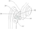
图6是本发明所述一种基于钢丝驱动下肢穿戴增强型外骨骼机器人中盆骨调整基座与髋关节的连接关系示意图三;6 is a schematic diagram 3 of the connection relationship between the pelvic bone adjustment base and the hip joint in a steel wire-driven lower limb wearing enhanced exoskeleton robot according to the present invention;
图7是本发明所述一种基于钢丝驱动下肢穿戴增强型外骨骼机器人的电路框图。FIG. 7 is a circuit block diagram of an enhanced exoskeleton robot based on a wire-driven lower limb wearable according to the present invention.
附图标记说明如下:The reference numerals are explained as follows:
1、背板基座;2、电池;3、髋关节驱动器;4、膝关节驱动器;5、髋关节绝对位置单元;6、膝关节绝对位置单元;7、盆骨调整基座;8、盆骨宽度调节锁定把手;9、盆骨软包;10、髋关节钢丝驱动链;11、钢丝转向结构件;12、转向滑轮一;13、转向滑轮二;14、髋关节外展内收转轴;15、外侧滑轮一;16、外侧滑轮二;17、髋关节屈伸伸展转轴;18、膝关节驱动转向滑轮;19、髋关节驱动定滑轮;20、髋关节外展内收结构;21、膝关节驱动钢丝;22、固定绑带一;23、髋关节力传感器;24、膝关节转轴;25、膝关节;26、膝关节定滑轮;27、固定绑带二;28、膝关节力传感器;29、踝关节弯曲伸展转轴;30、踝关节内外翻转轴;31、脚踝固定器;32、髋关节;33、小腿;34、足底效应器。1. Backplate base; 2. Battery; 3. Hip joint driver; 4. Knee joint driver; 5. Hip joint absolute position unit; 6. Knee joint absolute position unit; 7. Pelvic adjustment base; 8. Pelvic joint Bone width adjustment locking handle; 9. Pelvic soft pack; 10. Hip joint steel wire drive chain; 11. Steel wire steering structure; 12. Steering pulley one; 13. Steering pulley two; 14. Hip joint abduction and adduction shaft; 15. External pulley one; 16. External pulley two; 17. Hip joint flexion and extension shaft; 18. Knee joint driving steering pulley; 19. Hip joint driving fixed pulley; Driving wire; 22. Fixed strap one; 23. Hip joint force sensor; 24. Knee joint shaft; 25. Knee joint; 26. Knee joint fixed pulley; 27. Fixed strap two; 28. Knee joint force sensor; 29 , Ankle flexion and extension axis; 30, Ankle inversion axis; 31, Ankle immobilizer; 32, Hip joint; 33, Calf; 34, Plantar effector.
具体实施方式Detailed ways
下面结合附图对本发明作进一步说明:The present invention will be further described below in conjunction with the accompanying drawings:
如图1-图7所示,一种基于钢丝驱动下肢穿戴增强型外骨骼机器人,包括背板基座1、电池2、髋关节驱动器3和膝关节驱动器4,所述背板基座1一侧设置有电池2,电池2为此机器人的助力运动供电,所述电池2下方设置有所述髋关节驱动器3,所述髋关节驱动器3一侧设置有所述膝关节驱动器4,所述髋关节驱动器3和所述膝关节驱动器4为机器人的助力运动提供动力,所述髋关节驱动器3下方设置有髋关节绝对位置单元5,所述膝关节驱动器4下方设置有膝关节绝对位置单元6,所述背板基座1下方设置有盆骨调整基座7,所述盆骨调整基座7下方设置有盆骨宽度调节锁定把手8,所述盆骨宽度调节锁定把手8用来调整盆骨调整基座7的宽度,所述盆骨宽度调节锁定把手8下方设置有盆骨软包9,所述髋关节驱动器3和所述膝关节驱动器4两侧均设置有转向滑轮一12,所述转向滑轮一12一侧设置有转向滑轮二13,所述转向滑轮一12之间设置有髋关节钢丝驱动链10,所述转向滑轮二13之间设置有钢丝转向结构件11,所述转向滑轮二13一侧设置有外侧滑轮二16,所述转向滑轮一12、所述转向滑轮二13、所述侧向滑轮一以及所述侧向滑轮二用来传递动力,所述外侧滑轮二16一侧设置有髋关节外展内收转轴14,所述外侧滑轮二16下方设置有外侧滑轮一15,所述外侧滑轮一15一侧设置有髋关节屈伸伸展转轴17,所述髋关节屈伸伸展转轴17外围设置有膝关节驱动转向滑轮18,所述膝关节驱动转向滑轮18一侧设置有髋关节驱动定滑轮19,所述髋关节驱动定滑轮19一侧设置有髋关节外展内收结构20,所述膝关节驱动转向滑轮18上设置有膝关节驱动钢丝21,所述膝关节25驱动钢丝21用来传递动力,所述膝关节驱动转向滑轮18另一侧设置有髋关节32,所述髋关节32上设置有固定绑带二27,所述固定绑带二27上设置有髋关节力传感器23,所述髋关节力传感器23用来检测佩戴者大腿的发力情况,所述髋关节32下端设置有膝关节25,所述膝关节25与所述髋关节32之间设置有膝关节转轴24,所述膝关节25下方设置有小腿33,所述小腿33上设置有固定绑带一22,所述固定绑带一22上设置有膝关节力传感器28,所述膝关节力传感器28用来检测佩戴者小腿33的发力情况,所述小腿33侧壁上设置有膝关节定滑轮26,所述膝关节定滑轮26下方设置有脚踝固定器31,所述脚踝固定器31与所述小腿33之间设置有踝关节弯曲伸展转轴30,所述踝关节弯曲伸展转轴30下方设置有踝关节内外翻转轴30,所述脚踝固定器31下方设置有足底效应器34。As shown in Figures 1-7, an augmented exoskeleton robot based on wire-driven lower limb wear includes a backplane base 1, a
本实施例中,所述髋关节驱动器3以及所述膝关节驱动器4与所述背板基座1均通过螺钉连接,所述髋关节驱动器3以及所述膝关节驱动器4为此机器人的助理运动提供动力,所述髋关节驱动器3的型号为SRS-545SH,所述膝关节驱动器4的型号为SRS-545SH。In this embodiment, the hip joint driver 3 and the knee joint driver 4 are connected with the backplane base 1 by screws, and the hip joint driver 3 and the knee joint driver 4 are assistant motions of the robot. To provide power, the model of the hip joint driver 3 is SRS-545SH, and the model of the knee joint driver 4 is SRS-545SH.
本实施例中,所述电池2与所述背板基座1通过卡槽连接,所述电池2为此机器人供电,所述髋关节绝对位置单元5以及所述膝关节绝对位置单元6与所述背板基座1均通过螺钉连接。In this embodiment, the
本实施例中,所述盆骨调整基座7与所述背板基座1通过螺栓连接,所述盆骨宽度调节锁定把手8与所述盆骨调整基座7通过螺纹连接,所述盆骨软包9与所述盆骨调整基座7通过螺钉连接,所述盆骨宽度调节锁定把手8用来调节所述盆骨调整基座7的宽度。In this embodiment, the
本实施例中,所述转向滑轮一12以及所述转向滑轮二13均与所述盆骨调整基座7滚动连接,所述转向滑轮一12与所述转向滑轮二13通过所述髋关节钢丝驱动链10连接,所述髋关节钢丝驱动链10用来传递动力。In this embodiment, the
本实施例中,所述髋关节32与所述盆骨调整基座7通过所述髋关节屈伸伸展转轴17连接,所述外侧滑轮一15以及所述外侧滑轮二16均与所述髋关节32滚动连接。In this embodiment, the
本实施例中,所述髋关节驱动定滑轮19以及所述膝关节驱动转向滑轮18均与所述髋关节32滚动连接,所述髋关节驱动定滑轮19以及所述膝关节驱动转向滑轮18均用来传递动力。In this embodiment, the hip joint driving fixed
本实施例中,所述固定绑带二27与所述髋关节32通过螺钉连接,所述固定绑带二27与所述髋关节力传感器23通过螺钉连接,所述髋关节力传感器23的型号为SYS-01B。In this embodiment, the
本实施例中,所述小腿33与所述固定绑带一22通过螺钉连接,所述固定绑带一22与所述膝关节力传感器28通过螺钉连接,所述小腿33与所述髋关节32通过所述膝关节25连接,所述膝关节力传感器28的型号为SYS-01B。In this embodiment, the
本实施例中,所述脚踝固定器31与所述小腿33通过所述踝关节内外翻转轴30连接,所述足底效应器34与所述脚踝固定器31通过螺钉连接。In this embodiment, the
具体工作原理为:使用时首先通过所述盆骨宽度调节锁定把手8调整所述盆骨调整基座7的宽度,使其与佩戴者的盆骨宽度一致,然后以此将佩戴者的脚固定在所述脚踝固定器31上,将佩戴者的腿通过所述固定绑带一22和所述固定绑带二27固定,所述背板基座1固定在所述佩戴者的背部,所述髋关节力传感器23和所述膝关节力传感器28可以实时的检测佩戴者腿部的发力状况,所述电池2为此机器人供电,所述髋关节驱动器3和所述膝关节驱动器4可以根据所述髋关节力传感器23和所述膝关节力传感器28检测到佩戴者发力的情况,通过自主开发的嵌入式系统软件进行力补偿,跟随运动,助力运动控制,然后通过所述转向滑轮一12、所述转向滑轮二13、所述外侧滑轮一15和所述外侧滑轮二16进行力的传递,然后控制力矩的同步输出过程,将动力传递到髋关节32和膝关节25上,从而形成对使用者人体的助力协作,所述髋关节屈伸伸展转轴17和所述膝关节转轴24为佩戴者腿部运动提供两个带动力的自由度,所述踝关节内外翻转轴30、所述髋关节外展内收转轴14以及所述踝关节屈曲伸展转轴29为佩戴者腿部运动提供三个欠驱动自由度,可以充分保证佩戴者佩戴过程的舒适性,同时整体设计更加紧凑,轻量化,通过丝传动技术控制的佩戴者的髋关节和脚踝,有效减小了腿部结构尺寸,使得腿部刚性结构更加贴合人体关节,运动惯量大幅降低,机构紧凑。The specific working principle is: when in use, firstly adjust the width of the
以上显示和描述了本发明的基本原理、主要特征和优点。本行业的技术人员应该了解,本发明不受上述实施例的限制,上述实施例和说明书中描述的只是说明本发明的原理,在不脱离本发明精神和范围的前提下,本发明还会有各种变化和改进,这些变化和改进都落入要求保护的本发明范围内。The foregoing has shown and described the basic principles, main features and advantages of the present invention. Those skilled in the art should understand that the present invention is not limited by the above-mentioned embodiments, and the descriptions in the above-mentioned embodiments and the description are only to illustrate the principle of the present invention. Without departing from the spirit and scope of the present invention, the present invention will have Various changes and modifications fall within the scope of the claimed invention.
Claims (10)
Translated fromChinesePriority Applications (1)
| Application Number | Priority Date | Filing Date | Title |
|---|---|---|---|
| CN201811507269.3ACN111300377A (en) | 2018-12-11 | 2018-12-11 | Lower limb wearing enhanced exoskeleton robot based on steel wire driving |
Applications Claiming Priority (1)
| Application Number | Priority Date | Filing Date | Title |
|---|---|---|---|
| CN201811507269.3ACN111300377A (en) | 2018-12-11 | 2018-12-11 | Lower limb wearing enhanced exoskeleton robot based on steel wire driving |
Publications (1)
| Publication Number | Publication Date |
|---|---|
| CN111300377Atrue CN111300377A (en) | 2020-06-19 |
Family
ID=71150450
Family Applications (1)
| Application Number | Title | Priority Date | Filing Date |
|---|---|---|---|
| CN201811507269.3APendingCN111300377A (en) | 2018-12-11 | 2018-12-11 | Lower limb wearing enhanced exoskeleton robot based on steel wire driving |
Country Status (1)
| Country | Link |
|---|---|
| CN (1) | CN111300377A (en) |
Cited By (3)
| Publication number | Priority date | Publication date | Assignee | Title |
|---|---|---|---|---|
| CN113367941A (en)* | 2021-06-18 | 2021-09-10 | 南开大学 | Rigid knee joint exoskeleton |
| CN114886727A (en)* | 2022-04-02 | 2022-08-12 | 长春工业大学 | Wearable three-degree-of-freedom hip joint rehabilitation device |
| CN116118894A (en)* | 2021-11-15 | 2023-05-16 | 腾讯科技(深圳)有限公司 | Hip joint assembly and robot |
Citations (5)
| Publication number | Priority date | Publication date | Assignee | Title |
|---|---|---|---|---|
| US20110213599A1 (en)* | 2008-08-28 | 2011-09-01 | Raytheon Company | Method of Sizing Actuators for a Biomimetic Mechanical Joint |
| CN106826761A (en)* | 2017-01-22 | 2017-06-13 | 哈尔滨工业大学 | A kind of lower limb assistance exoskeleton robot based on steel wire drive gear ratio joint |
| CN106956243A (en)* | 2017-03-06 | 2017-07-18 | 武汉大学 | A kind of bionical lower limb exoskeleton robot driven based on rope |
| CN209717704U (en)* | 2018-12-11 | 2019-12-03 | 上海傲鲨智能科技有限公司 | A kind of enhanced exoskeleton robot of lower limb multi-joint wearing based on steel wire drive technology |
| CN118456392A (en)* | 2024-05-23 | 2024-08-09 | 西安交通大学 | A lasso-driven exoskeleton hip joint with parallel gravity compensation mechanism |
- 2018
- 2018-12-11CNCN201811507269.3Apatent/CN111300377A/enactivePending
Patent Citations (5)
| Publication number | Priority date | Publication date | Assignee | Title |
|---|---|---|---|---|
| US20110213599A1 (en)* | 2008-08-28 | 2011-09-01 | Raytheon Company | Method of Sizing Actuators for a Biomimetic Mechanical Joint |
| CN106826761A (en)* | 2017-01-22 | 2017-06-13 | 哈尔滨工业大学 | A kind of lower limb assistance exoskeleton robot based on steel wire drive gear ratio joint |
| CN106956243A (en)* | 2017-03-06 | 2017-07-18 | 武汉大学 | A kind of bionical lower limb exoskeleton robot driven based on rope |
| CN209717704U (en)* | 2018-12-11 | 2019-12-03 | 上海傲鲨智能科技有限公司 | A kind of enhanced exoskeleton robot of lower limb multi-joint wearing based on steel wire drive technology |
| CN118456392A (en)* | 2024-05-23 | 2024-08-09 | 西安交通大学 | A lasso-driven exoskeleton hip joint with parallel gravity compensation mechanism |
Cited By (5)
| Publication number | Priority date | Publication date | Assignee | Title |
|---|---|---|---|---|
| CN113367941A (en)* | 2021-06-18 | 2021-09-10 | 南开大学 | Rigid knee joint exoskeleton |
| CN116118894A (en)* | 2021-11-15 | 2023-05-16 | 腾讯科技(深圳)有限公司 | Hip joint assembly and robot |
| CN116118894B (en)* | 2021-11-15 | 2024-06-07 | 腾讯科技(深圳)有限公司 | Hip joint assembly and robot |
| CN114886727A (en)* | 2022-04-02 | 2022-08-12 | 长春工业大学 | Wearable three-degree-of-freedom hip joint rehabilitation device |
| CN114886727B (en)* | 2022-04-02 | 2024-05-14 | 长春工业大学 | Wearable three-degree-of-freedom hip joint rehabilitation device |
Similar Documents
| Publication | Publication Date | Title |
|---|---|---|
| CN204450526U (en) | The ectoskeleton servomechanism that a kind of pneumatic muscles drives | |
| CN104552276B (en) | The ectoskeleton servomechanism that pneumatic muscles drives | |
| EP3778138B1 (en) | Exoskeleton recovery power assisting device | |
| US11497672B2 (en) | Soft knee exoskeleton driven by negative-pressure linear actuator | |
| CN110303479B (en) | A wearable flexible knee exoskeleton and its control method | |
| CN111110519A (en) | A multi-sensing intelligent wearable lower limb exoskeleton robot | |
| CN111300377A (en) | Lower limb wearing enhanced exoskeleton robot based on steel wire driving | |
| CN113440372B (en) | Flexibly-driven knee joint exoskeleton | |
| CN115245446B (en) | Knee joint exoskeleton with rigidity adjusting and energy recovering functions and training method thereof | |
| CN108743224A (en) | Leg rehabilitation training and body-building exoskeleton robot | |
| CN217724039U (en) | Wearable flexible knee joint helping hand clothes | |
| CN108161909A (en) | A kind of bionical lower limb exoskeleton robot carried for auxiliary | |
| CN107690375A (en) | Portable power joint arrangement and lower limb assistance exoskeleton equipment and its control method | |
| CN108852756A (en) | The lower limb exoskeleton robot of gravity center shift driving | |
| CN113070866A (en) | Hip exoskeleton walking-aid robot driven by flexible joints | |
| CN109846675B (en) | Mechanical structure of lower limb walking trainer capable of being spliced and combined and rehabilitation walking aid mechanism thereof | |
| Mohri et al. | Development of non-rotating joint drive type gastrocnemius-reinforcing power assist suit for squat lifting | |
| CN109646246B (en) | Wearable lower limb exoskeleton robot stretching and bending device | |
| Shin et al. | Optimal design of multi-linked knee joint for lower limb wearable robot | |
| CN109464227B (en) | Multi-degree-of-freedom artificial limb arm joint | |
| Mohri et al. | Development of endoskeleton type knee auxiliary power assist suit using pneumatic artificial muscles | |
| Luo et al. | Design and development of a wearable lower limb exoskeleton robot | |
| Park et al. | Design and control of a powered lower limb orthosis using a cable-differential mechanism, COWALK-Mobile 2 | |
| CN209717704U (en) | A kind of enhanced exoskeleton robot of lower limb multi-joint wearing based on steel wire drive technology | |
| CN211220681U (en) | Lower limb multi-joint wearable enhanced exoskeleton based on lead screw transmission structure |
Legal Events
| Date | Code | Title | Description |
|---|---|---|---|
| PB01 | Publication | ||
| PB01 | Publication | ||
| SE01 | Entry into force of request for substantive examination | ||
| SE01 | Entry into force of request for substantive examination |