CN111299741A - Device and method for removing bubbles in vacuum brazing filler metal - Google Patents
Device and method for removing bubbles in vacuum brazing filler metalDownload PDFInfo
- Publication number
- CN111299741A CN111299741ACN202010210498.XACN202010210498ACN111299741ACN 111299741 ACN111299741 ACN 111299741ACN 202010210498 ACN202010210498 ACN 202010210498ACN 111299741 ACN111299741 ACN 111299741A
- Authority
- CN
- China
- Prior art keywords
- filler metal
- brazing filler
- air bubbles
- removing air
- vacuum brazing
- Prior art date
- Legal status (The legal status is an assumption and is not a legal conclusion. Google has not performed a legal analysis and makes no representation as to the accuracy of the status listed.)
- Withdrawn
Links
- 239000002184metalSubstances0.000titleclaimsabstractdescription53
- 229910052751metalInorganic materials0.000titleclaimsabstractdescription53
- 239000000945fillerSubstances0.000titleclaimsabstractdescription50
- 238000005219brazingMethods0.000titleclaimsabstractdescription49
- 238000000034methodMethods0.000titleclaimsabstractdescription12
- 230000002209hydrophobic effectEffects0.000claimsabstractdescription14
- 239000012982microporous membraneSubstances0.000claimsabstractdescription5
- 239000012528membraneSubstances0.000claimsdescription10
- 238000007789sealingMethods0.000claimsdescription5
- 238000003466weldingMethods0.000abstractdescription14
- 229910000679solderInorganic materials0.000abstractdescription11
- 150000002739metalsChemical class0.000abstractdescription6
- 230000008030eliminationEffects0.000abstractdescription3
- 238000003379elimination reactionMethods0.000abstractdescription3
- 238000007872degassingMethods0.000abstractdescription2
- 239000011248coating agentSubstances0.000abstract1
- 238000000576coating methodMethods0.000abstract1
- 238000005476solderingMethods0.000abstract1
- 239000007789gasSubstances0.000description13
- 239000011148porous materialSubstances0.000description7
- 238000005516engineering processMethods0.000description4
- 238000000926separation methodMethods0.000description4
- 239000007788liquidSubstances0.000description3
- 238000004519manufacturing processMethods0.000description3
- 230000008018meltingEffects0.000description3
- 238000002844meltingMethods0.000description3
- 239000010953base metalSubstances0.000description2
- 239000011230binding agentSubstances0.000description2
- 230000015572biosynthetic processEffects0.000description2
- 238000010586diagramMethods0.000description2
- 239000000843powderSubstances0.000description2
- 230000009286beneficial effectEffects0.000description1
- 238000004140cleaningMethods0.000description1
- 238000005260corrosionMethods0.000description1
- 230000007797corrosionEffects0.000description1
- 230000007423decreaseEffects0.000description1
- 230000000694effectsEffects0.000description1
- 238000002474experimental methodMethods0.000description1
- 238000001556precipitationMethods0.000description1
- 230000008439repair processEffects0.000description1
- 238000004062sedimentationMethods0.000description1
- 238000004088simulationMethods0.000description1
- 239000007787solidSubstances0.000description1
- 229910000601superalloyInorganic materials0.000description1
- 230000005514two-phase flowEffects0.000description1
Images
Classifications
- B—PERFORMING OPERATIONS; TRANSPORTING
- B23—MACHINE TOOLS; METAL-WORKING NOT OTHERWISE PROVIDED FOR
- B23K—SOLDERING OR UNSOLDERING; WELDING; CLADDING OR PLATING BY SOLDERING OR WELDING; CUTTING BY APPLYING HEAT LOCALLY, e.g. FLAME CUTTING; WORKING BY LASER BEAM
- B23K1/00—Soldering, e.g. brazing, or unsoldering
- B23K1/008—Soldering within a furnace
- B—PERFORMING OPERATIONS; TRANSPORTING
- B23—MACHINE TOOLS; METAL-WORKING NOT OTHERWISE PROVIDED FOR
- B23K—SOLDERING OR UNSOLDERING; WELDING; CLADDING OR PLATING BY SOLDERING OR WELDING; CUTTING BY APPLYING HEAT LOCALLY, e.g. FLAME CUTTING; WORKING BY LASER BEAM
- B23K3/00—Tools, devices, or special appurtenances for soldering, e.g. brazing, or unsoldering, not specially adapted for particular methods
- B23K3/06—Solder feeding devices; Solder melting pans
- B23K3/0607—Solder feeding devices
- B—PERFORMING OPERATIONS; TRANSPORTING
- B23—MACHINE TOOLS; METAL-WORKING NOT OTHERWISE PROVIDED FOR
- B23K—SOLDERING OR UNSOLDERING; WELDING; CLADDING OR PLATING BY SOLDERING OR WELDING; CUTTING BY APPLYING HEAT LOCALLY, e.g. FLAME CUTTING; WORKING BY LASER BEAM
- B23K3/00—Tools, devices, or special appurtenances for soldering, e.g. brazing, or unsoldering, not specially adapted for particular methods
- B23K3/08—Auxiliary devices therefor
Landscapes
- Engineering & Computer Science (AREA)
- Mechanical Engineering (AREA)
- Degasification And Air Bubble Elimination (AREA)
Abstract
Translated fromChinese
Description
Translated fromChinese技术领域technical field
本发明涉及真空焊接领域,具体地说,本发明涉及一种利用旋流分离以及梯度压力去除真空钎焊钎料中气泡的装置及方法。The invention relates to the field of vacuum welding, in particular to a device and method for removing air bubbles in vacuum brazing filler metals by utilizing cyclone separation and gradient pressure.
背景技术Background technique
真空钎焊相比于常规焊接,可以保证高温合金的焊接质量,由于真空钎焊钎料的湿润性和流动性良好,可以用来焊接更复杂和狭小通道的器件。利用钎料和母材熔点的不同,能够在避免母材熔化的情况下,加热到钎料融化温度,利用钎料融化后良好的流动性对各种复杂结构进行焊接,可以实现零件的批量生产,得到结构致密、变形小、综合性能高的焊接件。真空钎焊技术从上世纪四十年代开始至今,已经成为一种极有发展前途的焊接技术。Compared with conventional welding, vacuum brazing can ensure the welding quality of superalloys. Due to the good wettability and fluidity of vacuum brazing filler metals, it can be used to weld more complex and narrow-channel devices. Using the difference in melting point between the brazing filler metal and the base metal, it can be heated to the melting temperature of the brazing filler metal without melting the base metal, and various complex structures can be welded by the good fluidity of the melted brazing filler metal, which can realize the mass production of parts. , to obtain welded parts with dense structure, small deformation and high comprehensive performance. Since the beginning of the 1940s, vacuum brazing technology has become a very promising welding technology.
虽然真空钎焊技术得到了应用的广泛,但是真空钎焊也存在一系列的问题:热裂纹、气孔、晶间腐蚀、零件变形等。其中焊接气孔的危害有很多,比如降低焊接接头的严密性和塑性;减小焊缝有效截面而使接头的机械强度下降;如果是焊缝根部气孔或垂直气孔,可能造成应力集中,成为焊缝裂源;如果焊接器件为制造或修复压力容器,可能因气孔问题,返修次数超标,使容器报废,所以气孔的存在使焊接件寿命大幅降低。其中焊接时气孔形成的原因有多种,除了钎料熔融态和固态溶解气体的含量不同,会造成焊接气孔之外;粘结剂和金属粉末混合之后的焊接钎料本身含有气泡,这个是造成真空焊接形成气孔的主要原因。Although vacuum brazing technology has been widely used, there are also a series of problems in vacuum brazing: hot cracks, pores, intergranular corrosion, deformation of parts, etc. Among them, there are many hazards of welding pores, such as reducing the tightness and plasticity of the welded joint; reducing the effective section of the welding seam and reducing the mechanical strength of the joint; if it is a porosity at the root of the weld or a vertical porosity, it may cause stress concentration and become a welded seam Crack source; if the welding device is used for manufacturing or repairing pressure vessels, the number of repairs may exceed the standard due to the blowhole problem, and the vessel will be scrapped, so the existence of blowholes will greatly reduce the life of the weldment. Among them, there are many reasons for the formation of pores during welding. In addition to the difference in the content of the molten and solid dissolved gases of the solder, which will cause welding pores; the solder after the binder and the metal powder are mixed. The solder itself contains bubbles, which is caused by The main reason for the formation of pores in vacuum welding.
对于如何去除真空钎焊后形成的气孔,现如今,主要的解决方法是改善焊接的工艺行为,比如增大加热壁面过热度以及减小熔融金属表面张力的工艺行为,以及焊前清理焊件表面氧化膜等。对于粘结剂、焊接钎料自身含有的气泡所去除方法并不多,以自然沉降去除气泡为主,这种方式既耗时长,又会使混合均匀的焊接钎料发生金属粉末沉淀,影响焊接效果。因此需要一种新型技术可以快速有效地去除真空钎焊钎料里的气泡。As for how to remove the pores formed after vacuum brazing, nowadays, the main solution is to improve the process behavior of welding, such as increasing the superheat of the heated wall and reducing the surface tension of the molten metal, and cleaning the surface of the weldment before welding. oxide film, etc. There are not many ways to remove the bubbles contained in the binder and the brazing filler metal itself. The main method is to remove the air bubbles by natural sedimentation. This method is time-consuming and causes metal powder precipitation in the evenly mixed brazing filler metal, which affects the welding process. Effect. Therefore, there is a need for a new technology that can quickly and effectively remove air bubbles in vacuum brazing filler metals.
发明内容SUMMARY OF THE INVENTION
本发明的目的在于解决现有问题,提出了一种利用利用旋流分离以及梯度压力去除真空钎焊钎料中气泡的装置。The purpose of the present invention is to solve the existing problems, and proposes a device for removing air bubbles in vacuum brazing filler metals by utilizing cyclone separation and gradient pressure.
本发明的具体技术方案如下:The concrete technical scheme of the present invention is as follows:
一种去除真空钎焊钎料中气泡的装置,所述的装置包括螺旋腔体、支撑架、上下两个端盖、钎料进口、钎料出口、气相出口和疏水性微孔滤膜;所述的上下两个端盖均设有气相出口,气相出口位于装置中心,上端盖、下端盖上分别设有钎料进口和钎料出口;所述的支撑架设置于上下两个端盖之间,所述的疏水性微孔滤膜通过支撑架固定;支撑架外围设置螺旋叶片,支撑架、螺旋叶片、装置的外壳一起构成螺旋腔体。A device for removing air bubbles in vacuum brazing filler metal, the device comprises a spiral cavity, a support frame, upper and lower end caps, a filler metal inlet, a filler metal outlet, a gas phase outlet and a hydrophobic microporous filter membrane; Both the upper and lower end caps are provided with a gas phase outlet, the gas phase outlet is located in the center of the device, and the upper end cap and the lower end cap are respectively provided with a brazing filler metal inlet and a brazing filler metal outlet; the support frame is arranged between the upper and lower end caps The hydrophobic microporous filter membrane is fixed by a support frame; a spiral blade is arranged on the periphery of the support frame, and the support frame, the spiral blade and the casing of the device together form a spiral cavity.
进一步,所述螺旋叶片的圈数为6-15圈,外径为300-800mm。Further, the number of turns of the spiral blade is 6-15 turns, and the outer diameter is 300-800mm.
进一步,所述支撑架包括内外两个,套筒状,用于固定疏水性微孔滤膜的内侧和外侧。Further, the support frame includes two inner and outer, sleeve-shaped, and is used for fixing the inner and outer sides of the hydrophobic microporous filter membrane.
进一步,所述上下两个端盖和装置外壳之间设有两组密封圈,确保不会发生泄漏问题。Further, two sets of sealing rings are arranged between the upper and lower end caps and the device casing to ensure that no leakage problem occurs.
进一步,所述上下两个端盖和外壳的连接为螺栓螺母连接。Further, the connection between the upper and lower end caps and the housing is a bolt and nut connection.
一种去除真空钎焊钎料中气泡的方法,所述钎焊钎料经过动力单元提供一定的压力和流量,采用切向方向或者螺旋线方式由钎料进口进入装置,钎焊钎料中的气泡在离心力以及梯度压力的作用下向装置中心移动,经过疏水性微孔滤膜,由气相出口排出装置。A method for removing air bubbles in vacuum brazing filler metal. The bubbles move to the center of the device under the action of centrifugal force and gradient pressure, pass through the hydrophobic microporous filter membrane, and are discharged from the gas phase outlet.
由于采用的是螺旋腔体,当钎料进口方式为切向方向进入时,钎料会直接沿螺旋腔体运动,减少动能损失;以螺旋线方式进入上端盖时,钎料以螺旋方式进入腔体,同样会减少动能的损失。Since the spiral cavity is used, when the solder enters the tangential direction, the solder will move directly along the spiral cavity to reduce kinetic energy loss; when entering the upper end cover in a spiral way, the solder enters the cavity in a spiral way. body, it will also reduce the loss of kinetic energy.
本发明的有益效果在于:采用螺旋通道,既可以充分利用腔体内的梯度压力对钎焊钎料中气体的影响,将离心力和梯度压力有机结合在一起;又固定了钎焊钎料的流动路径,和其他除气装置相比,大幅降低了钎料的损耗。对于疏水性微孔滤膜的应用,在有效过滤气泡的同时,同样提高了对钎料的利用率。本发明设计的装置具有制作简单、高效以及成本造价低等特点,在功能上满足了去除真空钎焊钎料内部气泡的问题。The beneficial effect of the invention is that: by adopting the spiral channel, the influence of the gradient pressure in the cavity on the gas in the brazing filler metal can be fully utilized, and the centrifugal force and the gradient pressure can be organically combined; and the flow path of the brazing filler metal can be fixed. , Compared with other degassing devices, the loss of solder is greatly reduced. For the application of the hydrophobic microporous membrane, the utilization rate of the solder is also improved while the air bubbles are effectively filtered. The device designed by the invention has the characteristics of simple manufacture, high efficiency and low cost, and functionally satisfies the problem of removing bubbles in the vacuum brazing filler metal.
附图说明Description of drawings
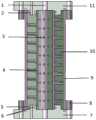
图1为该气泡去除装置的结构示意图。FIG. 1 is a schematic structural diagram of the bubble removing device.
图中:1气相出口;2钎料进口;3疏水性微孔滤膜;4支撑架;5钎料出口;6两组密封圈;7下端盖;8螺栓用通孔;9外壳;10螺旋腔体;11上端盖。In the figure: 1 gas phase outlet; 2 solder inlet; 3 hydrophobic microporous membrane; 4 support frame; 5 solder outlet; 6 two sets of sealing rings; 7 lower end cover; 8 through holes for bolts; 9 shell; 10 screw Cavity; 11 upper end cap.
具体实施方式Detailed ways
通过仿真、实验等研究发现,在该气泡消除装置内的径向截面存在显著的压力梯度,即径向位置从外到内压力逐渐减小。根据亨利定律,在该截面高度附近,气泡消除装置的外壁液体压力高、中心压力低,在该压力下钎焊钎料中的气泡可运动到中心位置,所以将气相出口设置在该装置的中心位置,有利于钎焊钎料中气泡的进一步去除。该装置将目前只利用离心力场分离二相流提升为利用离心力场以及梯度压力场相结合,去除液体中的气体。Through simulation and experiments, it is found that there is a significant pressure gradient in the radial section of the bubble elimination device, that is, the radial pressure gradually decreases from the outside to the inside. According to Henry's law, near the height of the section, the liquid pressure of the outer wall of the bubble elimination device is high and the center pressure is low. Under this pressure, the bubbles in the brazing filler metal can move to the center position, so the gas phase outlet is set at the center of the device. position, which is conducive to the further removal of air bubbles in the brazing filler metal. The device improves the separation of the two-phase flow by using the centrifugal force field at present to the combination of the centrifugal force field and the gradient pressure field to remove the gas in the liquid.
请参阅图1,为本发明利用旋流分离以及梯度压力去除真空钎焊钎料中气泡的装置结构示意图,该装置包含一个螺旋腔体10、上端盖7、下端盖11,该装置上下两个端盖处分别设有未处理钎焊钎料进口2和去除气泡之后的钎料出口5,且均设有气相出口1,气相出口1位于装置中心上下两端,钎焊钎料经过动力单元提供一定的压力和流量,从钎料进口2进入装置,气泡在离心力以及梯度压力的作用下向装置中心移动,经过疏水性微孔滤膜3,由气相出口1排出装置。疏水性微孔滤膜3由支撑架4所固定,其中疏水性微孔滤膜孔径为0.8μm,足以确保气体可以通过但液体不能通过,上端盖7、下端盖11和外壳9之间连接为螺栓螺母连接,并在上下端盖内部开O型槽,用两组密封圈6确保不会发生泄漏。上述的钎焊钎料进口方式可采用切向方向或者螺旋线方式进入。在整个装置中,气泡会在离心力场以及梯度压力场相结合下,排出装置。Please refer to FIG. 1 , which is a schematic diagram of the structure of the device for removing air bubbles in vacuum brazing filler metals using cyclone separation and gradient pressure according to the present invention. The device includes a
Claims (9)
Translated fromChinesePriority Applications (1)
| Application Number | Priority Date | Filing Date | Title |
|---|---|---|---|
| CN202010210498.XACN111299741A (en) | 2020-03-24 | 2020-03-24 | Device and method for removing bubbles in vacuum brazing filler metal |
Applications Claiming Priority (1)
| Application Number | Priority Date | Filing Date | Title |
|---|---|---|---|
| CN202010210498.XACN111299741A (en) | 2020-03-24 | 2020-03-24 | Device and method for removing bubbles in vacuum brazing filler metal |
Publications (1)
| Publication Number | Publication Date |
|---|---|
| CN111299741Atrue CN111299741A (en) | 2020-06-19 |
Family
ID=71151382
Family Applications (1)
| Application Number | Title | Priority Date | Filing Date |
|---|---|---|---|
| CN202010210498.XAWithdrawnCN111299741A (en) | 2020-03-24 | 2020-03-24 | Device and method for removing bubbles in vacuum brazing filler metal |
Country Status (1)
| Country | Link |
|---|---|
| CN (1) | CN111299741A (en) |
Cited By (2)
| Publication number | Priority date | Publication date | Assignee | Title |
|---|---|---|---|---|
| CN115533233A (en)* | 2022-11-03 | 2022-12-30 | 大连理工大学 | Welding structure for laser brazing of optical assembly and using method thereof |
| CN115945812A (en)* | 2022-04-01 | 2023-04-11 | 苏州索雷特自动化科技有限公司 | Bubble removing mechanism and bubble removing method for battery piece cutting spray |
Citations (10)
| Publication number | Priority date | Publication date | Assignee | Title |
|---|---|---|---|---|
| US3161490A (en)* | 1960-11-01 | 1964-12-15 | Edmund F Dudek | Gas-liquid separator |
| CN1268068A (en)* | 1997-08-26 | 2000-09-27 | 巴西石油公司 | Improved helical separator |
| US6322616B1 (en)* | 2000-02-24 | 2001-11-27 | Sdh, Inc. | Gas separator for an oil well production line |
| US6863712B1 (en)* | 2002-09-25 | 2005-03-08 | The United States Of America As Represented By The Administrator Of The National Aeronautics And Space Administration | Fluid bubble eliminator |
| US20050217489A1 (en)* | 2004-04-02 | 2005-10-06 | Innovative Engineering Systems Ltd. | Device for the separation of the gas phase from a mixture of fluid/gas for use in hydrocarbons producing and injection wells |
| CN102094617A (en)* | 2011-01-18 | 2011-06-15 | 中国石油化工股份有限公司 | Pitch-variable spiral gas anchor |
| US20130233174A1 (en)* | 2010-10-20 | 2013-09-12 | Cameron International Corporation | Separator with a helix assembly |
| RU2583268C1 (en)* | 2014-11-21 | 2016-05-10 | Открытое акционерное общество "Уфимское моторостроительное производственное объединение" ОАО "УМПО" | Gas-liquid separator |
| CN107557087A (en)* | 2017-09-05 | 2018-01-09 | 中石化广州工程有限公司 | A kind of spiral-flow type gas-liquid separation device and method |
| CN107970645A (en)* | 2017-11-30 | 2018-05-01 | 陈炳坤(天津)生物技术有限公司 | A kind of high efficient gas and liquid separator |
- 2020
- 2020-03-24CNCN202010210498.XApatent/CN111299741A/ennot_activeWithdrawn
Patent Citations (10)
| Publication number | Priority date | Publication date | Assignee | Title |
|---|---|---|---|---|
| US3161490A (en)* | 1960-11-01 | 1964-12-15 | Edmund F Dudek | Gas-liquid separator |
| CN1268068A (en)* | 1997-08-26 | 2000-09-27 | 巴西石油公司 | Improved helical separator |
| US6322616B1 (en)* | 2000-02-24 | 2001-11-27 | Sdh, Inc. | Gas separator for an oil well production line |
| US6863712B1 (en)* | 2002-09-25 | 2005-03-08 | The United States Of America As Represented By The Administrator Of The National Aeronautics And Space Administration | Fluid bubble eliminator |
| US20050217489A1 (en)* | 2004-04-02 | 2005-10-06 | Innovative Engineering Systems Ltd. | Device for the separation of the gas phase from a mixture of fluid/gas for use in hydrocarbons producing and injection wells |
| US20130233174A1 (en)* | 2010-10-20 | 2013-09-12 | Cameron International Corporation | Separator with a helix assembly |
| CN102094617A (en)* | 2011-01-18 | 2011-06-15 | 中国石油化工股份有限公司 | Pitch-variable spiral gas anchor |
| RU2583268C1 (en)* | 2014-11-21 | 2016-05-10 | Открытое акционерное общество "Уфимское моторостроительное производственное объединение" ОАО "УМПО" | Gas-liquid separator |
| CN107557087A (en)* | 2017-09-05 | 2018-01-09 | 中石化广州工程有限公司 | A kind of spiral-flow type gas-liquid separation device and method |
| CN107970645A (en)* | 2017-11-30 | 2018-05-01 | 陈炳坤(天津)生物技术有限公司 | A kind of high efficient gas and liquid separator |
Cited By (2)
| Publication number | Priority date | Publication date | Assignee | Title |
|---|---|---|---|---|
| CN115945812A (en)* | 2022-04-01 | 2023-04-11 | 苏州索雷特自动化科技有限公司 | Bubble removing mechanism and bubble removing method for battery piece cutting spray |
| CN115533233A (en)* | 2022-11-03 | 2022-12-30 | 大连理工大学 | Welding structure for laser brazing of optical assembly and using method thereof |
Similar Documents
| Publication | Publication Date | Title |
|---|---|---|
| CN111299741A (en) | Device and method for removing bubbles in vacuum brazing filler metal | |
| CN111098051B (en) | An iron-aluminum-based intermetallic compound filter element and its preparation method | |
| CN100586638C (en) | A manufacturing process suitable for fusion reactor cladding containing flow channel components | |
| CN108568160A (en) | A kind of high-temperature nickel-base alloy multistage filter and manufacturing method | |
| CN214319614U (en) | a high pressure filter | |
| CN203904764U (en) | Novel slag separator shell | |
| CN113782235A (en) | Experimental device and experimental method for blasting process of steam generator heat transfer tube rupture accident | |
| CN202398137U (en) | Multiphase material separating device | |
| CN205752452U (en) | A kind of cooler bin in New-energy electric vehicle | |
| CN219986521U (en) | Oily medium auxiliary laser processing device | |
| CN103831525A (en) | Aluminum bar and copper ring friction welding device and method for appliance switches | |
| CN108889028A (en) | Nuclear power station main pump emergency injection water system filter device | |
| CN110315668B (en) | Novel steel epoxy sleeve repairing method | |
| CN205370676U (en) | Stainless steel shell -and -tube oil cooler | |
| CN108817323A (en) | A kind of casting pouring filter and casting pouring method | |
| CN211727994U (en) | Iron-aluminum-based intermetallic compound filter element | |
| CN204387537U (en) | A kind of exhaust pipe flange | |
| CN203978904U (en) | A kind of large centrifugal bearing of compressor case Oil-gas Separation apparatus | |
| CN201100630Y (en) | Stress Relief Trough Oil Slurry Steam Generator | |
| CN203550741U (en) | Welding-type air heater water inlet-outlet pipe connector | |
| CN216653863U (en) | Vacuum degassing stove dry-type filter | |
| CN113739607A (en) | Method for manufacturing a heat pipe and heat pipe | |
| CN111282349A (en) | A compressed air purifier | |
| CN221156111U (en) | Adopt sealed low viscosity liquid filter equipment of screw thread | |
| CN221906007U (en) | Filter device for rocket propellant transfer |
Legal Events
| Date | Code | Title | Description |
|---|---|---|---|
| PB01 | Publication | ||
| PB01 | Publication | ||
| SE01 | Entry into force of request for substantive examination | ||
| SE01 | Entry into force of request for substantive examination | ||
| WW01 | Invention patent application withdrawn after publication | Application publication date:20200619 | |
| WW01 | Invention patent application withdrawn after publication |