CN111295718A - Mechanical force based control of electrical power output - Google Patents
Mechanical force based control of electrical power outputDownload PDFInfo
- Publication number
- CN111295718A CN111295718ACN201880071061.3ACN201880071061ACN111295718ACN 111295718 ACN111295718 ACN 111295718ACN 201880071061 ACN201880071061 ACN 201880071061ACN 111295718 ACN111295718 ACN 111295718A
- Authority
- CN
- China
- Prior art keywords
- needle
- surgical
- tissue
- jaw
- instrument
- Prior art date
- Legal status (The legal status is an assumption and is not a legal conclusion. Google has not performed a legal analysis and makes no representation as to the accuracy of the status listed.)
- Granted
Links
Images


Classifications
- A—HUMAN NECESSITIES
- A61—MEDICAL OR VETERINARY SCIENCE; HYGIENE
- A61B—DIAGNOSIS; SURGERY; IDENTIFICATION
- A61B17/00—Surgical instruments, devices or methods
- A61B17/12—Surgical instruments, devices or methods for ligaturing or otherwise compressing tubular parts of the body, e.g. blood vessels or umbilical cord
- A61B17/128—Surgical instruments, devices or methods for ligaturing or otherwise compressing tubular parts of the body, e.g. blood vessels or umbilical cord for applying or removing clamps or clips
- A61B17/1285—Surgical instruments, devices or methods for ligaturing or otherwise compressing tubular parts of the body, e.g. blood vessels or umbilical cord for applying or removing clamps or clips for minimally invasive surgery
- A—HUMAN NECESSITIES
- A61—MEDICAL OR VETERINARY SCIENCE; HYGIENE
- A61B—DIAGNOSIS; SURGERY; IDENTIFICATION
- A61B17/00—Surgical instruments, devices or methods
- A61B17/04—Surgical instruments, devices or methods for suturing wounds; Holders or packages for needles or suture materials
- A61B17/0469—Suturing instruments for use in minimally invasive surgery, e.g. endoscopic surgery
- A—HUMAN NECESSITIES
- A61—MEDICAL OR VETERINARY SCIENCE; HYGIENE
- A61B—DIAGNOSIS; SURGERY; IDENTIFICATION
- A61B17/00—Surgical instruments, devices or methods
- A61B17/04—Surgical instruments, devices or methods for suturing wounds; Holders or packages for needles or suture materials
- A61B17/0482—Needle or suture guides
- A—HUMAN NECESSITIES
- A61—MEDICAL OR VETERINARY SCIENCE; HYGIENE
- A61B—DIAGNOSIS; SURGERY; IDENTIFICATION
- A61B17/00—Surgical instruments, devices or methods
- A61B17/04—Surgical instruments, devices or methods for suturing wounds; Holders or packages for needles or suture materials
- A61B17/06—Needles ; Sutures; Needle-suture combinations; Holders or packages for needles or suture materials
- A61B17/06114—Packages or dispensers for needles or sutures
- A—HUMAN NECESSITIES
- A61—MEDICAL OR VETERINARY SCIENCE; HYGIENE
- A61B—DIAGNOSIS; SURGERY; IDENTIFICATION
- A61B17/00—Surgical instruments, devices or methods
- A61B17/04—Surgical instruments, devices or methods for suturing wounds; Holders or packages for needles or suture materials
- A61B17/06—Needles ; Sutures; Needle-suture combinations; Holders or packages for needles or suture materials
- A61B17/062—Needle manipulators
- A—HUMAN NECESSITIES
- A61—MEDICAL OR VETERINARY SCIENCE; HYGIENE
- A61B—DIAGNOSIS; SURGERY; IDENTIFICATION
- A61B17/00—Surgical instruments, devices or methods
- A61B17/12—Surgical instruments, devices or methods for ligaturing or otherwise compressing tubular parts of the body, e.g. blood vessels or umbilical cord
- A61B17/122—Clamps or clips, e.g. for the umbilical cord
- A61B17/1222—Packages or dispensers therefor
- A—HUMAN NECESSITIES
- A61—MEDICAL OR VETERINARY SCIENCE; HYGIENE
- A61B—DIAGNOSIS; SURGERY; IDENTIFICATION
- A61B17/00—Surgical instruments, devices or methods
- A61B17/12—Surgical instruments, devices or methods for ligaturing or otherwise compressing tubular parts of the body, e.g. blood vessels or umbilical cord
- A61B17/122—Clamps or clips, e.g. for the umbilical cord
- A61B17/1227—Spring clips
- A—HUMAN NECESSITIES
- A61—MEDICAL OR VETERINARY SCIENCE; HYGIENE
- A61B—DIAGNOSIS; SURGERY; IDENTIFICATION
- A61B17/00—Surgical instruments, devices or methods
- A61B17/28—Surgical forceps
- A61B17/285—Surgical forceps combined with cutting implements
- A—HUMAN NECESSITIES
- A61—MEDICAL OR VETERINARY SCIENCE; HYGIENE
- A61B—DIAGNOSIS; SURGERY; IDENTIFICATION
- A61B17/00—Surgical instruments, devices or methods
- A61B17/28—Surgical forceps
- A61B17/29—Forceps for use in minimally invasive surgery
- A—HUMAN NECESSITIES
- A61—MEDICAL OR VETERINARY SCIENCE; HYGIENE
- A61B—DIAGNOSIS; SURGERY; IDENTIFICATION
- A61B17/00—Surgical instruments, devices or methods
- A61B17/28—Surgical forceps
- A61B17/29—Forceps for use in minimally invasive surgery
- A61B17/2909—Handles
- A—HUMAN NECESSITIES
- A61—MEDICAL OR VETERINARY SCIENCE; HYGIENE
- A61B—DIAGNOSIS; SURGERY; IDENTIFICATION
- A61B17/00—Surgical instruments, devices or methods
- A61B17/28—Surgical forceps
- A61B17/29—Forceps for use in minimally invasive surgery
- A61B17/295—Forceps for use in minimally invasive surgery combined with cutting implements
- A—HUMAN NECESSITIES
- A61—MEDICAL OR VETERINARY SCIENCE; HYGIENE
- A61B—DIAGNOSIS; SURGERY; IDENTIFICATION
- A61B17/00—Surgical instruments, devices or methods
- A61B17/32—Surgical cutting instruments
- A61B17/320068—Surgical cutting instruments using mechanical vibrations, e.g. ultrasonic
- A—HUMAN NECESSITIES
- A61—MEDICAL OR VETERINARY SCIENCE; HYGIENE
- A61B—DIAGNOSIS; SURGERY; IDENTIFICATION
- A61B17/00—Surgical instruments, devices or methods
- A61B17/34—Trocars; Puncturing needles
- A61B17/3417—Details of tips or shafts, e.g. grooves, expandable, bendable; Multiple coaxial sliding cannulas, e.g. for dilating
- A61B17/3421—Cannulas
- A—HUMAN NECESSITIES
- A61—MEDICAL OR VETERINARY SCIENCE; HYGIENE
- A61B—DIAGNOSIS; SURGERY; IDENTIFICATION
- A61B18/00—Surgical instruments, devices or methods for transferring non-mechanical forms of energy to or from the body
- A61B18/04—Surgical instruments, devices or methods for transferring non-mechanical forms of energy to or from the body by heating
- A61B18/12—Surgical instruments, devices or methods for transferring non-mechanical forms of energy to or from the body by heating by passing a current through the tissue to be heated, e.g. high-frequency current
- A61B18/14—Probes or electrodes therefor
- A61B18/1442—Probes having pivoting end effectors, e.g. forceps
- A61B18/1445—Probes having pivoting end effectors, e.g. forceps at the distal end of a shaft, e.g. forceps or scissors at the end of a rigid rod
- A—HUMAN NECESSITIES
- A61—MEDICAL OR VETERINARY SCIENCE; HYGIENE
- A61B—DIAGNOSIS; SURGERY; IDENTIFICATION
- A61B34/00—Computer-aided surgery; Manipulators or robots specially adapted for use in surgery
- A61B34/30—Surgical robots
- A—HUMAN NECESSITIES
- A61—MEDICAL OR VETERINARY SCIENCE; HYGIENE
- A61B—DIAGNOSIS; SURGERY; IDENTIFICATION
- A61B34/00—Computer-aided surgery; Manipulators or robots specially adapted for use in surgery
- A61B34/70—Manipulators specially adapted for use in surgery
- A61B34/76—Manipulators having means for providing feel, e.g. force or tactile feedback
- A—HUMAN NECESSITIES
- A61—MEDICAL OR VETERINARY SCIENCE; HYGIENE
- A61B—DIAGNOSIS; SURGERY; IDENTIFICATION
- A61B90/00—Instruments, implements or accessories specially adapted for surgery or diagnosis and not covered by any of the groups A61B1/00 - A61B50/00, e.g. for luxation treatment or for protecting wound edges
- A61B90/03—Automatic limiting or abutting means, e.g. for safety
- A—HUMAN NECESSITIES
- A61—MEDICAL OR VETERINARY SCIENCE; HYGIENE
- A61B—DIAGNOSIS; SURGERY; IDENTIFICATION
- A61B90/00—Instruments, implements or accessories specially adapted for surgery or diagnosis and not covered by any of the groups A61B1/00 - A61B50/00, e.g. for luxation treatment or for protecting wound edges
- A61B90/90—Identification means for patients or instruments, e.g. tags
- A61B90/98—Identification means for patients or instruments, e.g. tags using electromagnetic means, e.g. transponders
- G—PHYSICS
- G16—INFORMATION AND COMMUNICATION TECHNOLOGY [ICT] SPECIALLY ADAPTED FOR SPECIFIC APPLICATION FIELDS
- G16H—HEALTHCARE INFORMATICS, i.e. INFORMATION AND COMMUNICATION TECHNOLOGY [ICT] SPECIALLY ADAPTED FOR THE HANDLING OR PROCESSING OF MEDICAL OR HEALTHCARE DATA
- G16H40/00—ICT specially adapted for the management or administration of healthcare resources or facilities; ICT specially adapted for the management or operation of medical equipment or devices
- G16H40/20—ICT specially adapted for the management or administration of healthcare resources or facilities; ICT specially adapted for the management or operation of medical equipment or devices for the management or administration of healthcare resources or facilities, e.g. managing hospital staff or surgery rooms
- G—PHYSICS
- G16—INFORMATION AND COMMUNICATION TECHNOLOGY [ICT] SPECIALLY ADAPTED FOR SPECIFIC APPLICATION FIELDS
- G16H—HEALTHCARE INFORMATICS, i.e. INFORMATION AND COMMUNICATION TECHNOLOGY [ICT] SPECIALLY ADAPTED FOR THE HANDLING OR PROCESSING OF MEDICAL OR HEALTHCARE DATA
- G16H40/00—ICT specially adapted for the management or administration of healthcare resources or facilities; ICT specially adapted for the management or operation of medical equipment or devices
- G16H40/60—ICT specially adapted for the management or administration of healthcare resources or facilities; ICT specially adapted for the management or operation of medical equipment or devices for the operation of medical equipment or devices
- G16H40/63—ICT specially adapted for the management or administration of healthcare resources or facilities; ICT specially adapted for the management or operation of medical equipment or devices for the operation of medical equipment or devices for local operation
- G—PHYSICS
- G16—INFORMATION AND COMMUNICATION TECHNOLOGY [ICT] SPECIALLY ADAPTED FOR SPECIFIC APPLICATION FIELDS
- G16H—HEALTHCARE INFORMATICS, i.e. INFORMATION AND COMMUNICATION TECHNOLOGY [ICT] SPECIALLY ADAPTED FOR THE HANDLING OR PROCESSING OF MEDICAL OR HEALTHCARE DATA
- G16H40/00—ICT specially adapted for the management or administration of healthcare resources or facilities; ICT specially adapted for the management or operation of medical equipment or devices
- G16H40/60—ICT specially adapted for the management or administration of healthcare resources or facilities; ICT specially adapted for the management or operation of medical equipment or devices for the operation of medical equipment or devices
- G16H40/67—ICT specially adapted for the management or administration of healthcare resources or facilities; ICT specially adapted for the management or operation of medical equipment or devices for the operation of medical equipment or devices for remote operation
- G—PHYSICS
- G16—INFORMATION AND COMMUNICATION TECHNOLOGY [ICT] SPECIALLY ADAPTED FOR SPECIFIC APPLICATION FIELDS
- G16H—HEALTHCARE INFORMATICS, i.e. INFORMATION AND COMMUNICATION TECHNOLOGY [ICT] SPECIALLY ADAPTED FOR THE HANDLING OR PROCESSING OF MEDICAL OR HEALTHCARE DATA
- G16H50/00—ICT specially adapted for medical diagnosis, medical simulation or medical data mining; ICT specially adapted for detecting, monitoring or modelling epidemics or pandemics
- G16H50/70—ICT specially adapted for medical diagnosis, medical simulation or medical data mining; ICT specially adapted for detecting, monitoring or modelling epidemics or pandemics for mining of medical data, e.g. analysing previous cases of other patients
- A—HUMAN NECESSITIES
- A61—MEDICAL OR VETERINARY SCIENCE; HYGIENE
- A61B—DIAGNOSIS; SURGERY; IDENTIFICATION
- A61B17/00—Surgical instruments, devices or methods
- A61B17/04—Surgical instruments, devices or methods for suturing wounds; Holders or packages for needles or suture materials
- A61B17/06—Needles ; Sutures; Needle-suture combinations; Holders or packages for needles or suture materials
- A—HUMAN NECESSITIES
- A61—MEDICAL OR VETERINARY SCIENCE; HYGIENE
- A61B—DIAGNOSIS; SURGERY; IDENTIFICATION
- A61B17/00—Surgical instruments, devices or methods
- A61B17/068—Surgical staplers, e.g. containing multiple staples or clamps
- A—HUMAN NECESSITIES
- A61—MEDICAL OR VETERINARY SCIENCE; HYGIENE
- A61B—DIAGNOSIS; SURGERY; IDENTIFICATION
- A61B17/00—Surgical instruments, devices or methods
- A61B17/32—Surgical cutting instruments
- A61B17/3201—Scissors
- A—HUMAN NECESSITIES
- A61—MEDICAL OR VETERINARY SCIENCE; HYGIENE
- A61B—DIAGNOSIS; SURGERY; IDENTIFICATION
- A61B17/00—Surgical instruments, devices or methods
- A61B17/34—Trocars; Puncturing needles
- A61B17/3417—Details of tips or shafts, e.g. grooves, expandable, bendable; Multiple coaxial sliding cannulas, e.g. for dilating
- A—HUMAN NECESSITIES
- A61—MEDICAL OR VETERINARY SCIENCE; HYGIENE
- A61B—DIAGNOSIS; SURGERY; IDENTIFICATION
- A61B17/00—Surgical instruments, devices or methods
- A61B2017/00017—Electrical control of surgical instruments
- A—HUMAN NECESSITIES
- A61—MEDICAL OR VETERINARY SCIENCE; HYGIENE
- A61B—DIAGNOSIS; SURGERY; IDENTIFICATION
- A61B17/00—Surgical instruments, devices or methods
- A61B2017/00017—Electrical control of surgical instruments
- A61B2017/00022—Sensing or detecting at the treatment site
- A61B2017/00039—Electric or electromagnetic phenomena other than conductivity, e.g. capacity, inductivity, Hall effect
- A—HUMAN NECESSITIES
- A61—MEDICAL OR VETERINARY SCIENCE; HYGIENE
- A61B—DIAGNOSIS; SURGERY; IDENTIFICATION
- A61B17/00—Surgical instruments, devices or methods
- A61B2017/00017—Electrical control of surgical instruments
- A61B2017/00115—Electrical control of surgical instruments with audible or visual output
- A61B2017/00119—Electrical control of surgical instruments with audible or visual output alarm; indicating an abnormal situation
- A61B2017/00123—Electrical control of surgical instruments with audible or visual output alarm; indicating an abnormal situation and automatic shutdown
- A—HUMAN NECESSITIES
- A61—MEDICAL OR VETERINARY SCIENCE; HYGIENE
- A61B—DIAGNOSIS; SURGERY; IDENTIFICATION
- A61B17/00—Surgical instruments, devices or methods
- A61B2017/00017—Electrical control of surgical instruments
- A61B2017/00115—Electrical control of surgical instruments with audible or visual output
- A61B2017/00128—Electrical control of surgical instruments with audible or visual output related to intensity or progress of surgical action
- A—HUMAN NECESSITIES
- A61—MEDICAL OR VETERINARY SCIENCE; HYGIENE
- A61B—DIAGNOSIS; SURGERY; IDENTIFICATION
- A61B17/00—Surgical instruments, devices or methods
- A61B2017/00017—Electrical control of surgical instruments
- A61B2017/00137—Details of operation mode
- A61B2017/00154—Details of operation mode pulsed
- A61B2017/00172—Pulse trains, bursts, intermittent continuous operation
- A—HUMAN NECESSITIES
- A61—MEDICAL OR VETERINARY SCIENCE; HYGIENE
- A61B—DIAGNOSIS; SURGERY; IDENTIFICATION
- A61B17/00—Surgical instruments, devices or methods
- A61B2017/00017—Electrical control of surgical instruments
- A61B2017/00221—Electrical control of surgical instruments with wireless transmission of data, e.g. by infrared radiation or radiowaves
- A—HUMAN NECESSITIES
- A61—MEDICAL OR VETERINARY SCIENCE; HYGIENE
- A61B—DIAGNOSIS; SURGERY; IDENTIFICATION
- A61B17/00—Surgical instruments, devices or methods
- A61B2017/0023—Surgical instruments, devices or methods disposable
- A—HUMAN NECESSITIES
- A61—MEDICAL OR VETERINARY SCIENCE; HYGIENE
- A61B—DIAGNOSIS; SURGERY; IDENTIFICATION
- A61B17/00—Surgical instruments, devices or methods
- A61B17/00234—Surgical instruments, devices or methods for minimally invasive surgery
- A61B2017/00292—Surgical instruments, devices or methods for minimally invasive surgery mounted on or guided by flexible, e.g. catheter-like, means
- A61B2017/003—Steerable
- A61B2017/00305—Constructional details of the flexible means
- A61B2017/00309—Cut-outs or slits
- A—HUMAN NECESSITIES
- A61—MEDICAL OR VETERINARY SCIENCE; HYGIENE
- A61B—DIAGNOSIS; SURGERY; IDENTIFICATION
- A61B17/00—Surgical instruments, devices or methods
- A61B17/00234—Surgical instruments, devices or methods for minimally invasive surgery
- A61B2017/00292—Surgical instruments, devices or methods for minimally invasive surgery mounted on or guided by flexible, e.g. catheter-like, means
- A61B2017/003—Steerable
- A61B2017/00318—Steering mechanisms
- A61B2017/00323—Cables or rods
- A61B2017/00327—Cables or rods with actuating members moving in opposite directions
- A—HUMAN NECESSITIES
- A61—MEDICAL OR VETERINARY SCIENCE; HYGIENE
- A61B—DIAGNOSIS; SURGERY; IDENTIFICATION
- A61B17/00—Surgical instruments, devices or methods
- A61B17/00234—Surgical instruments, devices or methods for minimally invasive surgery
- A61B2017/00353—Surgical instruments, devices or methods for minimally invasive surgery one mechanical instrument performing multiple functions, e.g. cutting and grasping
- A—HUMAN NECESSITIES
- A61—MEDICAL OR VETERINARY SCIENCE; HYGIENE
- A61B—DIAGNOSIS; SURGERY; IDENTIFICATION
- A61B17/00—Surgical instruments, devices or methods
- A61B2017/00367—Details of actuation of instruments, e.g. relations between pushing buttons, or the like, and activation of the tool, working tip, or the like
- A61B2017/00389—Button or wheel for performing multiple functions, e.g. rotation of shaft and end effector
- A61B2017/00393—Button or wheel for performing multiple functions, e.g. rotation of shaft and end effector with means for switching between functions
- A—HUMAN NECESSITIES
- A61—MEDICAL OR VETERINARY SCIENCE; HYGIENE
- A61B—DIAGNOSIS; SURGERY; IDENTIFICATION
- A61B17/00—Surgical instruments, devices or methods
- A61B2017/00367—Details of actuation of instruments, e.g. relations between pushing buttons, or the like, and activation of the tool, working tip, or the like
- A61B2017/00398—Details of actuation of instruments, e.g. relations between pushing buttons, or the like, and activation of the tool, working tip, or the like using powered actuators, e.g. stepper motors, solenoids
- A—HUMAN NECESSITIES
- A61—MEDICAL OR VETERINARY SCIENCE; HYGIENE
- A61B—DIAGNOSIS; SURGERY; IDENTIFICATION
- A61B17/00—Surgical instruments, devices or methods
- A61B2017/00367—Details of actuation of instruments, e.g. relations between pushing buttons, or the like, and activation of the tool, working tip, or the like
- A61B2017/00407—Ratchet means
- A—HUMAN NECESSITIES
- A61—MEDICAL OR VETERINARY SCIENCE; HYGIENE
- A61B—DIAGNOSIS; SURGERY; IDENTIFICATION
- A61B17/00—Surgical instruments, devices or methods
- A61B2017/0042—Surgical instruments, devices or methods with special provisions for gripping
- A61B2017/00424—Surgical instruments, devices or methods with special provisions for gripping ergonomic, e.g. fitting in fist
- A—HUMAN NECESSITIES
- A61—MEDICAL OR VETERINARY SCIENCE; HYGIENE
- A61B—DIAGNOSIS; SURGERY; IDENTIFICATION
- A61B17/00—Surgical instruments, devices or methods
- A61B2017/0046—Surgical instruments, devices or methods with a releasable handle; with handle and operating part separable
- A—HUMAN NECESSITIES
- A61—MEDICAL OR VETERINARY SCIENCE; HYGIENE
- A61B—DIAGNOSIS; SURGERY; IDENTIFICATION
- A61B17/00—Surgical instruments, devices or methods
- A61B2017/0046—Surgical instruments, devices or methods with a releasable handle; with handle and operating part separable
- A61B2017/00464—Surgical instruments, devices or methods with a releasable handle; with handle and operating part separable for use with different instruments
- A—HUMAN NECESSITIES
- A61—MEDICAL OR VETERINARY SCIENCE; HYGIENE
- A61B—DIAGNOSIS; SURGERY; IDENTIFICATION
- A61B17/00—Surgical instruments, devices or methods
- A61B2017/0046—Surgical instruments, devices or methods with a releasable handle; with handle and operating part separable
- A61B2017/00473—Distal part, e.g. tip or head
- A—HUMAN NECESSITIES
- A61—MEDICAL OR VETERINARY SCIENCE; HYGIENE
- A61B—DIAGNOSIS; SURGERY; IDENTIFICATION
- A61B17/00—Surgical instruments, devices or methods
- A61B2017/00477—Coupling
- A—HUMAN NECESSITIES
- A61—MEDICAL OR VETERINARY SCIENCE; HYGIENE
- A61B—DIAGNOSIS; SURGERY; IDENTIFICATION
- A61B17/00—Surgical instruments, devices or methods
- A61B2017/00477—Coupling
- A61B2017/00482—Coupling with a code
- A—HUMAN NECESSITIES
- A61—MEDICAL OR VETERINARY SCIENCE; HYGIENE
- A61B—DIAGNOSIS; SURGERY; IDENTIFICATION
- A61B17/00—Surgical instruments, devices or methods
- A61B2017/00526—Methods of manufacturing
- A—HUMAN NECESSITIES
- A61—MEDICAL OR VETERINARY SCIENCE; HYGIENE
- A61B—DIAGNOSIS; SURGERY; IDENTIFICATION
- A61B17/00—Surgical instruments, devices or methods
- A61B2017/00681—Aspects not otherwise provided for
- A61B2017/00734—Aspects not otherwise provided for battery operated
- A—HUMAN NECESSITIES
- A61—MEDICAL OR VETERINARY SCIENCE; HYGIENE
- A61B—DIAGNOSIS; SURGERY; IDENTIFICATION
- A61B17/00—Surgical instruments, devices or methods
- A61B2017/00831—Material properties
- A61B2017/00876—Material properties magnetic
- A—HUMAN NECESSITIES
- A61—MEDICAL OR VETERINARY SCIENCE; HYGIENE
- A61B—DIAGNOSIS; SURGERY; IDENTIFICATION
- A61B17/00—Surgical instruments, devices or methods
- A61B17/04—Surgical instruments, devices or methods for suturing wounds; Holders or packages for needles or suture materials
- A61B17/06—Needles ; Sutures; Needle-suture combinations; Holders or packages for needles or suture materials
- A61B17/06066—Needles, e.g. needle tip configurations
- A61B2017/06076—Needles, e.g. needle tip configurations helically or spirally coiled
- A—HUMAN NECESSITIES
- A61—MEDICAL OR VETERINARY SCIENCE; HYGIENE
- A61B—DIAGNOSIS; SURGERY; IDENTIFICATION
- A61B17/00—Surgical instruments, devices or methods
- A61B17/04—Surgical instruments, devices or methods for suturing wounds; Holders or packages for needles or suture materials
- A61B17/06—Needles ; Sutures; Needle-suture combinations; Holders or packages for needles or suture materials
- A61B17/06066—Needles, e.g. needle tip configurations
- A61B2017/0608—J-shaped
- A—HUMAN NECESSITIES
- A61—MEDICAL OR VETERINARY SCIENCE; HYGIENE
- A61B—DIAGNOSIS; SURGERY; IDENTIFICATION
- A61B17/00—Surgical instruments, devices or methods
- A61B17/28—Surgical forceps
- A61B17/2812—Surgical forceps with a single pivotal connection
- A61B17/282—Jaws
- A61B2017/2825—Inserts of different material in jaws
- A—HUMAN NECESSITIES
- A61—MEDICAL OR VETERINARY SCIENCE; HYGIENE
- A61B—DIAGNOSIS; SURGERY; IDENTIFICATION
- A61B17/00—Surgical instruments, devices or methods
- A61B17/28—Surgical forceps
- A61B17/29—Forceps for use in minimally invasive surgery
- A61B2017/2901—Details of shaft
- A61B2017/2902—Details of shaft characterized by features of the actuating rod
- A61B2017/2903—Details of shaft characterized by features of the actuating rod transferring rotary motion
- A—HUMAN NECESSITIES
- A61—MEDICAL OR VETERINARY SCIENCE; HYGIENE
- A61B—DIAGNOSIS; SURGERY; IDENTIFICATION
- A61B17/00—Surgical instruments, devices or methods
- A61B17/28—Surgical forceps
- A61B17/29—Forceps for use in minimally invasive surgery
- A61B17/2909—Handles
- A61B2017/291—Handles the position of the handle being adjustable with respect to the shaft
- A—HUMAN NECESSITIES
- A61—MEDICAL OR VETERINARY SCIENCE; HYGIENE
- A61B—DIAGNOSIS; SURGERY; IDENTIFICATION
- A61B17/00—Surgical instruments, devices or methods
- A61B17/28—Surgical forceps
- A61B17/29—Forceps for use in minimally invasive surgery
- A61B2017/2926—Details of heads or jaws
- A—HUMAN NECESSITIES
- A61—MEDICAL OR VETERINARY SCIENCE; HYGIENE
- A61B—DIAGNOSIS; SURGERY; IDENTIFICATION
- A61B17/00—Surgical instruments, devices or methods
- A61B17/28—Surgical forceps
- A61B17/29—Forceps for use in minimally invasive surgery
- A61B2017/2926—Details of heads or jaws
- A61B2017/2927—Details of heads or jaws the angular position of the head being adjustable with respect to the shaft
- A61B2017/2929—Details of heads or jaws the angular position of the head being adjustable with respect to the shaft with a head rotatable about the longitudinal axis of the shaft
- A—HUMAN NECESSITIES
- A61—MEDICAL OR VETERINARY SCIENCE; HYGIENE
- A61B—DIAGNOSIS; SURGERY; IDENTIFICATION
- A61B17/00—Surgical instruments, devices or methods
- A61B17/28—Surgical forceps
- A61B17/29—Forceps for use in minimally invasive surgery
- A61B2017/2926—Details of heads or jaws
- A61B2017/2931—Details of heads or jaws with releasable head
- A—HUMAN NECESSITIES
- A61—MEDICAL OR VETERINARY SCIENCE; HYGIENE
- A61B—DIAGNOSIS; SURGERY; IDENTIFICATION
- A61B17/00—Surgical instruments, devices or methods
- A61B17/28—Surgical forceps
- A61B17/29—Forceps for use in minimally invasive surgery
- A61B2017/2926—Details of heads or jaws
- A61B2017/2932—Transmission of forces to jaw members
- A61B2017/2933—Transmission of forces to jaw members camming or guiding means
- A—HUMAN NECESSITIES
- A61—MEDICAL OR VETERINARY SCIENCE; HYGIENE
- A61B—DIAGNOSIS; SURGERY; IDENTIFICATION
- A61B17/00—Surgical instruments, devices or methods
- A61B17/28—Surgical forceps
- A61B17/29—Forceps for use in minimally invasive surgery
- A61B2017/2926—Details of heads or jaws
- A61B2017/2932—Transmission of forces to jaw members
- A61B2017/2943—Toothed members, e.g. rack and pinion
- A—HUMAN NECESSITIES
- A61—MEDICAL OR VETERINARY SCIENCE; HYGIENE
- A61B—DIAGNOSIS; SURGERY; IDENTIFICATION
- A61B17/00—Surgical instruments, devices or methods
- A61B17/28—Surgical forceps
- A61B17/29—Forceps for use in minimally invasive surgery
- A61B2017/2926—Details of heads or jaws
- A61B2017/2945—Curved jaws
- A—HUMAN NECESSITIES
- A61—MEDICAL OR VETERINARY SCIENCE; HYGIENE
- A61B—DIAGNOSIS; SURGERY; IDENTIFICATION
- A61B17/00—Surgical instruments, devices or methods
- A61B17/32—Surgical cutting instruments
- A61B2017/320044—Blunt dissectors
- A—HUMAN NECESSITIES
- A61—MEDICAL OR VETERINARY SCIENCE; HYGIENE
- A61B—DIAGNOSIS; SURGERY; IDENTIFICATION
- A61B18/00—Surgical instruments, devices or methods for transferring non-mechanical forms of energy to or from the body
- A61B2018/00053—Mechanical features of the instrument of device
- A61B2018/00059—Material properties
- A61B2018/00071—Electrical conductivity
- A61B2018/00083—Electrical conductivity low, i.e. electrically insulating
- A—HUMAN NECESSITIES
- A61—MEDICAL OR VETERINARY SCIENCE; HYGIENE
- A61B—DIAGNOSIS; SURGERY; IDENTIFICATION
- A61B18/00—Surgical instruments, devices or methods for transferring non-mechanical forms of energy to or from the body
- A61B2018/00053—Mechanical features of the instrument of device
- A61B2018/00107—Coatings on the energy applicator
- A61B2018/00136—Coatings on the energy applicator with polymer
- A—HUMAN NECESSITIES
- A61—MEDICAL OR VETERINARY SCIENCE; HYGIENE
- A61B—DIAGNOSIS; SURGERY; IDENTIFICATION
- A61B18/00—Surgical instruments, devices or methods for transferring non-mechanical forms of energy to or from the body
- A61B2018/00053—Mechanical features of the instrument of device
- A61B2018/00172—Connectors and adapters therefor
- A61B2018/00178—Electrical connectors
- A—HUMAN NECESSITIES
- A61—MEDICAL OR VETERINARY SCIENCE; HYGIENE
- A61B—DIAGNOSIS; SURGERY; IDENTIFICATION
- A61B18/00—Surgical instruments, devices or methods for transferring non-mechanical forms of energy to or from the body
- A61B2018/00315—Surgical instruments, devices or methods for transferring non-mechanical forms of energy to or from the body for treatment of particular body parts
- A61B2018/00345—Vascular system
- A61B2018/00404—Blood vessels other than those in or around the heart
- A—HUMAN NECESSITIES
- A61—MEDICAL OR VETERINARY SCIENCE; HYGIENE
- A61B—DIAGNOSIS; SURGERY; IDENTIFICATION
- A61B18/00—Surgical instruments, devices or methods for transferring non-mechanical forms of energy to or from the body
- A61B2018/00571—Surgical instruments, devices or methods for transferring non-mechanical forms of energy to or from the body for achieving a particular surgical effect
- A61B2018/00577—Ablation
- A—HUMAN NECESSITIES
- A61—MEDICAL OR VETERINARY SCIENCE; HYGIENE
- A61B—DIAGNOSIS; SURGERY; IDENTIFICATION
- A61B18/00—Surgical instruments, devices or methods for transferring non-mechanical forms of energy to or from the body
- A61B2018/00571—Surgical instruments, devices or methods for transferring non-mechanical forms of energy to or from the body for achieving a particular surgical effect
- A61B2018/00601—Cutting
- A—HUMAN NECESSITIES
- A61—MEDICAL OR VETERINARY SCIENCE; HYGIENE
- A61B—DIAGNOSIS; SURGERY; IDENTIFICATION
- A61B18/00—Surgical instruments, devices or methods for transferring non-mechanical forms of energy to or from the body
- A61B2018/00571—Surgical instruments, devices or methods for transferring non-mechanical forms of energy to or from the body for achieving a particular surgical effect
- A61B2018/0063—Sealing
- A—HUMAN NECESSITIES
- A61—MEDICAL OR VETERINARY SCIENCE; HYGIENE
- A61B—DIAGNOSIS; SURGERY; IDENTIFICATION
- A61B18/00—Surgical instruments, devices or methods for transferring non-mechanical forms of energy to or from the body
- A61B2018/00636—Sensing and controlling the application of energy
- A61B2018/00642—Sensing and controlling the application of energy with feedback, i.e. closed loop control
- A—HUMAN NECESSITIES
- A61—MEDICAL OR VETERINARY SCIENCE; HYGIENE
- A61B—DIAGNOSIS; SURGERY; IDENTIFICATION
- A61B18/00—Surgical instruments, devices or methods for transferring non-mechanical forms of energy to or from the body
- A61B2018/00636—Sensing and controlling the application of energy
- A61B2018/00666—Sensing and controlling the application of energy using a threshold value
- A61B2018/00672—Sensing and controlling the application of energy using a threshold value lower
- A—HUMAN NECESSITIES
- A61—MEDICAL OR VETERINARY SCIENCE; HYGIENE
- A61B—DIAGNOSIS; SURGERY; IDENTIFICATION
- A61B18/00—Surgical instruments, devices or methods for transferring non-mechanical forms of energy to or from the body
- A61B2018/00636—Sensing and controlling the application of energy
- A61B2018/00666—Sensing and controlling the application of energy using a threshold value
- A61B2018/00678—Sensing and controlling the application of energy using a threshold value upper
- A—HUMAN NECESSITIES
- A61—MEDICAL OR VETERINARY SCIENCE; HYGIENE
- A61B—DIAGNOSIS; SURGERY; IDENTIFICATION
- A61B18/00—Surgical instruments, devices or methods for transferring non-mechanical forms of energy to or from the body
- A61B2018/00636—Sensing and controlling the application of energy
- A61B2018/00696—Controlled or regulated parameters
- A61B2018/00702—Power or energy
- A—HUMAN NECESSITIES
- A61—MEDICAL OR VETERINARY SCIENCE; HYGIENE
- A61B—DIAGNOSIS; SURGERY; IDENTIFICATION
- A61B18/00—Surgical instruments, devices or methods for transferring non-mechanical forms of energy to or from the body
- A61B2018/00636—Sensing and controlling the application of energy
- A61B2018/00696—Controlled or regulated parameters
- A61B2018/0072—Current
- A—HUMAN NECESSITIES
- A61—MEDICAL OR VETERINARY SCIENCE; HYGIENE
- A61B—DIAGNOSIS; SURGERY; IDENTIFICATION
- A61B18/00—Surgical instruments, devices or methods for transferring non-mechanical forms of energy to or from the body
- A61B2018/00636—Sensing and controlling the application of energy
- A61B2018/00773—Sensed parameters
- A61B2018/00827—Current
- A—HUMAN NECESSITIES
- A61—MEDICAL OR VETERINARY SCIENCE; HYGIENE
- A61B—DIAGNOSIS; SURGERY; IDENTIFICATION
- A61B18/00—Surgical instruments, devices or methods for transferring non-mechanical forms of energy to or from the body
- A61B2018/00636—Sensing and controlling the application of energy
- A61B2018/00773—Sensed parameters
- A61B2018/00875—Resistance or impedance
- A—HUMAN NECESSITIES
- A61—MEDICAL OR VETERINARY SCIENCE; HYGIENE
- A61B—DIAGNOSIS; SURGERY; IDENTIFICATION
- A61B18/00—Surgical instruments, devices or methods for transferring non-mechanical forms of energy to or from the body
- A61B2018/00636—Sensing and controlling the application of energy
- A61B2018/00773—Sensed parameters
- A61B2018/00892—Voltage
- A—HUMAN NECESSITIES
- A61—MEDICAL OR VETERINARY SCIENCE; HYGIENE
- A61B—DIAGNOSIS; SURGERY; IDENTIFICATION
- A61B18/00—Surgical instruments, devices or methods for transferring non-mechanical forms of energy to or from the body
- A61B18/04—Surgical instruments, devices or methods for transferring non-mechanical forms of energy to or from the body by heating
- A61B18/12—Surgical instruments, devices or methods for transferring non-mechanical forms of energy to or from the body by heating by passing a current through the tissue to be heated, e.g. high-frequency current
- A61B18/14—Probes or electrodes therefor
- A61B18/1442—Probes having pivoting end effectors, e.g. forceps
- A61B2018/1452—Probes having pivoting end effectors, e.g. forceps including means for cutting
- A61B2018/1457—Probes having pivoting end effectors, e.g. forceps including means for cutting having opposing blades cutting tissue grasped by the jaws, i.e. combined scissors and pliers
- A—HUMAN NECESSITIES
- A61—MEDICAL OR VETERINARY SCIENCE; HYGIENE
- A61B—DIAGNOSIS; SURGERY; IDENTIFICATION
- A61B18/00—Surgical instruments, devices or methods for transferring non-mechanical forms of energy to or from the body
- A61B18/04—Surgical instruments, devices or methods for transferring non-mechanical forms of energy to or from the body by heating
- A61B18/12—Surgical instruments, devices or methods for transferring non-mechanical forms of energy to or from the body by heating by passing a current through the tissue to be heated, e.g. high-frequency current
- A61B18/14—Probes or electrodes therefor
- A61B18/1442—Probes having pivoting end effectors, e.g. forceps
- A61B2018/146—Scissors
- A—HUMAN NECESSITIES
- A61—MEDICAL OR VETERINARY SCIENCE; HYGIENE
- A61B—DIAGNOSIS; SURGERY; IDENTIFICATION
- A61B34/00—Computer-aided surgery; Manipulators or robots specially adapted for use in surgery
- A61B34/30—Surgical robots
- A61B2034/305—Details of wrist mechanisms at distal ends of robotic arms
- A—HUMAN NECESSITIES
- A61—MEDICAL OR VETERINARY SCIENCE; HYGIENE
- A61B—DIAGNOSIS; SURGERY; IDENTIFICATION
- A61B90/00—Instruments, implements or accessories specially adapted for surgery or diagnosis and not covered by any of the groups A61B1/00 - A61B50/00, e.g. for luxation treatment or for protecting wound edges
- A61B90/03—Automatic limiting or abutting means, e.g. for safety
- A61B2090/031—Automatic limiting or abutting means, e.g. for safety torque limiting
- A—HUMAN NECESSITIES
- A61—MEDICAL OR VETERINARY SCIENCE; HYGIENE
- A61B—DIAGNOSIS; SURGERY; IDENTIFICATION
- A61B90/00—Instruments, implements or accessories specially adapted for surgery or diagnosis and not covered by any of the groups A61B1/00 - A61B50/00, e.g. for luxation treatment or for protecting wound edges
- A61B90/03—Automatic limiting or abutting means, e.g. for safety
- A61B2090/032—Automatic limiting or abutting means, e.g. for safety pressure limiting, e.g. hydrostatic
- A—HUMAN NECESSITIES
- A61—MEDICAL OR VETERINARY SCIENCE; HYGIENE
- A61B—DIAGNOSIS; SURGERY; IDENTIFICATION
- A61B90/00—Instruments, implements or accessories specially adapted for surgery or diagnosis and not covered by any of the groups A61B1/00 - A61B50/00, e.g. for luxation treatment or for protecting wound edges
- A61B90/03—Automatic limiting or abutting means, e.g. for safety
- A61B2090/033—Abutting means, stops, e.g. abutting on tissue or skin
- A61B2090/034—Abutting means, stops, e.g. abutting on tissue or skin abutting on parts of the device itself
- A61B2090/035—Abutting means, stops, e.g. abutting on tissue or skin abutting on parts of the device itself preventing further rotation
- A—HUMAN NECESSITIES
- A61—MEDICAL OR VETERINARY SCIENCE; HYGIENE
- A61B—DIAGNOSIS; SURGERY; IDENTIFICATION
- A61B90/00—Instruments, implements or accessories specially adapted for surgery or diagnosis and not covered by any of the groups A61B1/00 - A61B50/00, e.g. for luxation treatment or for protecting wound edges
- A61B90/06—Measuring instruments not otherwise provided for
- A61B2090/061—Measuring instruments not otherwise provided for for measuring dimensions, e.g. length
- A—HUMAN NECESSITIES
- A61—MEDICAL OR VETERINARY SCIENCE; HYGIENE
- A61B—DIAGNOSIS; SURGERY; IDENTIFICATION
- A61B90/00—Instruments, implements or accessories specially adapted for surgery or diagnosis and not covered by any of the groups A61B1/00 - A61B50/00, e.g. for luxation treatment or for protecting wound edges
- A61B90/06—Measuring instruments not otherwise provided for
- A61B2090/064—Measuring instruments not otherwise provided for for measuring force, pressure or mechanical tension
- A61B2090/065—Measuring instruments not otherwise provided for for measuring force, pressure or mechanical tension for measuring contact or contact pressure
- A—HUMAN NECESSITIES
- A61—MEDICAL OR VETERINARY SCIENCE; HYGIENE
- A61B—DIAGNOSIS; SURGERY; IDENTIFICATION
- A61B90/00—Instruments, implements or accessories specially adapted for surgery or diagnosis and not covered by any of the groups A61B1/00 - A61B50/00, e.g. for luxation treatment or for protecting wound edges
- A61B90/08—Accessories or related features not otherwise provided for
- A61B2090/0803—Counting the number of times an instrument is used
- A—HUMAN NECESSITIES
- A61—MEDICAL OR VETERINARY SCIENCE; HYGIENE
- A61B—DIAGNOSIS; SURGERY; IDENTIFICATION
- A61B90/00—Instruments, implements or accessories specially adapted for surgery or diagnosis and not covered by any of the groups A61B1/00 - A61B50/00, e.g. for luxation treatment or for protecting wound edges
- A61B90/08—Accessories or related features not otherwise provided for
- A61B2090/0807—Indication means
- A61B2090/0808—Indication means for indicating correct assembly of components, e.g. of the surgical apparatus
- A—HUMAN NECESSITIES
- A61—MEDICAL OR VETERINARY SCIENCE; HYGIENE
- A61B—DIAGNOSIS; SURGERY; IDENTIFICATION
- A61B90/00—Instruments, implements or accessories specially adapted for surgery or diagnosis and not covered by any of the groups A61B1/00 - A61B50/00, e.g. for luxation treatment or for protecting wound edges
- A61B90/08—Accessories or related features not otherwise provided for
- A61B2090/0807—Indication means
- A61B2090/0811—Indication means for the position of a particular part of an instrument with respect to the rest of the instrument, e.g. position of the anvil of a stapling instrument
- A—HUMAN NECESSITIES
- A61—MEDICAL OR VETERINARY SCIENCE; HYGIENE
- A61B—DIAGNOSIS; SURGERY; IDENTIFICATION
- A61B90/00—Instruments, implements or accessories specially adapted for surgery or diagnosis and not covered by any of the groups A61B1/00 - A61B50/00, e.g. for luxation treatment or for protecting wound edges
- A61B90/08—Accessories or related features not otherwise provided for
- A61B2090/0814—Preventing re-use
- A—HUMAN NECESSITIES
- A61—MEDICAL OR VETERINARY SCIENCE; HYGIENE
- A61B—DIAGNOSIS; SURGERY; IDENTIFICATION
- A61B2562/00—Details of sensors; Constructional details of sensor housings or probes; Accessories for sensors
- A61B2562/02—Details of sensors specially adapted for in-vivo measurements
- A61B2562/0261—Strain gauges
- A—HUMAN NECESSITIES
- A61—MEDICAL OR VETERINARY SCIENCE; HYGIENE
- A61B—DIAGNOSIS; SURGERY; IDENTIFICATION
- A61B2562/00—Details of sensors; Constructional details of sensor housings or probes; Accessories for sensors
- A61B2562/04—Arrangements of multiple sensors of the same type
- A61B2562/043—Arrangements of multiple sensors of the same type in a linear array
- B—PERFORMING OPERATIONS; TRANSPORTING
- B33—ADDITIVE MANUFACTURING TECHNOLOGY
- B33Y—ADDITIVE MANUFACTURING, i.e. MANUFACTURING OF THREE-DIMENSIONAL [3-D] OBJECTS BY ADDITIVE DEPOSITION, ADDITIVE AGGLOMERATION OR ADDITIVE LAYERING, e.g. BY 3-D PRINTING, STEREOLITHOGRAPHY OR SELECTIVE LASER SINTERING
- B33Y80/00—Products made by additive manufacturing
- G—PHYSICS
- G01—MEASURING; TESTING
- G01L—MEASURING FORCE, STRESS, TORQUE, WORK, MECHANICAL POWER, MECHANICAL EFFICIENCY, OR FLUID PRESSURE
- G01L1/00—Measuring force or stress, in general
- G01L1/20—Measuring force or stress, in general by measuring variations in ohmic resistance of solid materials or of electrically-conductive fluids; by making use of electrokinetic cells, i.e. liquid-containing cells wherein an electrical potential is produced or varied upon the application of stress
- G01L1/22—Measuring force or stress, in general by measuring variations in ohmic resistance of solid materials or of electrically-conductive fluids; by making use of electrokinetic cells, i.e. liquid-containing cells wherein an electrical potential is produced or varied upon the application of stress using resistance strain gauges
- Y—GENERAL TAGGING OF NEW TECHNOLOGICAL DEVELOPMENTS; GENERAL TAGGING OF CROSS-SECTIONAL TECHNOLOGIES SPANNING OVER SEVERAL SECTIONS OF THE IPC; TECHNICAL SUBJECTS COVERED BY FORMER USPC CROSS-REFERENCE ART COLLECTIONS [XRACs] AND DIGESTS
- Y02—TECHNOLOGIES OR APPLICATIONS FOR MITIGATION OR ADAPTATION AGAINST CLIMATE CHANGE
- Y02E—REDUCTION OF GREENHOUSE GAS [GHG] EMISSIONS, RELATED TO ENERGY GENERATION, TRANSMISSION OR DISTRIBUTION
- Y02E60/00—Enabling technologies; Technologies with a potential or indirect contribution to GHG emissions mitigation
- Y02E60/10—Energy storage using batteries
Landscapes
- Health & Medical Sciences (AREA)
- Life Sciences & Earth Sciences (AREA)
- Surgery (AREA)
- Engineering & Computer Science (AREA)
- Biomedical Technology (AREA)
- Public Health (AREA)
- Medical Informatics (AREA)
- General Health & Medical Sciences (AREA)
- Veterinary Medicine (AREA)
- Animal Behavior & Ethology (AREA)
- Molecular Biology (AREA)
- Heart & Thoracic Surgery (AREA)
- Nuclear Medicine, Radiotherapy & Molecular Imaging (AREA)
- Reproductive Health (AREA)
- Vascular Medicine (AREA)
- Epidemiology (AREA)
- Ophthalmology & Optometry (AREA)
- General Business, Economics & Management (AREA)
- Business, Economics & Management (AREA)
- Primary Health Care (AREA)
- Pathology (AREA)
- Oral & Maxillofacial Surgery (AREA)
- Data Mining & Analysis (AREA)
- Robotics (AREA)
- Dentistry (AREA)
- Physics & Mathematics (AREA)
- Databases & Information Systems (AREA)
- Mechanical Engineering (AREA)
- Plasma & Fusion (AREA)
- Otolaryngology (AREA)
- Electromagnetism (AREA)
- Surgical Instruments (AREA)
Abstract
Description
Translated fromChinese相关申请的交叉引用CROSS-REFERENCE TO RELATED APPLICATIONS
本申请要求于2018年8月24日提交的名称为“ELECTRICAL POWER OUTPUT CONTROLBASED ON MECHANICAL FORCES”的美国非临时专利申请序列号16/112,180的权益,该申请的公开内容全文以引用方式并入本文。本申请要求于2018年4月19日提交的名称为“METHODOF HUB COMMUNICATION”的美国临时专利申请序列号62/659,900的权益,该申请的公开内容全文以引用方式并入本文。本专利申请要求以下专利申请的权益:2018年5月1日提交的名称为“MODULAR SURGICAL INSTRUMENTS”的美国临时专利申请序列号62/665,128;2018年5月1日提交的名称为“SURGICAL SUTURING SYSTEMS”的美国临时专利申请序列号62/665,129;2018年5月1日提交的名称为“SURGICAL CLIP APPLIER”的美国临时专利申请序列号62/665,134;2018年5月1日提交的名称为“SURGICAL INSTRUMENTS COMPRISING CONTROLSYSTEMS”的美国临时专利申请序列号62/665,139;2018年5月1日提交的名称为“SURGICALINSTRUMENTS COMPRISING HANDLE ARRANGEMENTS”的美国临时专利申请序列号62/665,177;以及2018年5月1日提交的名称为“SURGICAL DISSECTORS”的美国临时专利申请序列号62/665,192,这些申请的公开内容全文以引用方式并入本文。本专利申请要求以下专利申请的权益:2018年3月28日提交的名称为“USE OF LASER LIGHT AND RED-GREEN-BLUECOLORATION TO DETERMINE PROPERTIES OF BACK SCATTERED LIGHT”的美国临时专利申请序列号62/649,291;2018年3月28日提交的名称为“DATA STRIPPING METHOD TOINTERROGATE PATIENT RECORDS AND CREATE ANONYMIZED RECORD”的美国临时专利申请序列号62/649,294;2018年3月28日提交的名称为“ADAPTIVE CONTROL PROGRAM UPDATES FORSURGICAL DEVICES”的美国临时专利申请序列号62/649,296;2018年3月28日提交的名称为“SURGICAL HUB SITUATIONAL AWARENESS”的美国临时专利申请序列号62/649,300;2018年3月28日提交的名称为“INTERACTIVE SURGICAL SYSTEMS WITH ENCRYPTED COMMUNICATIONCAPABILITIES”的美国临时专利申请序列号62/649,302;2018年3月28日提交的名称为“AUTOMATIC TOOL ADJUSTMENTS FOR ROBOT-ASSISTED SURGICAL PLATFORMS”的美国临时专利申请序列号62/649,307;2018年3月28日提交的名称为“SURGICAL HUB SPATIALAWARENESS TO DETERMINE DEVICES IN OPERATING THEATER”的美国临时专利申请序列号62/649,309;2018年3月28日提交的名称为“COMPUTER IMPLEMENTED INTERACTIVESURGICAL SYSTEMS”的美国临时专利申请序列号62/649,310;2018年3月28日提交的名称为“CLOUD INTERFACE FOR COUPLED SURGICAL DEVICES”的美国专利申请序列号62/649,313;2018年3月28日提交的名称为“DATA HANDLING AND PRIORITIZATION IN A CLOUDANALYTICS NETWORK”的美国临时专利申请序列号62/649,315;2018年3月28日提交的名称为“DRIVE ARRANGEMENTS FOR ROBOT-ASSISTED SURGICAL PLATFORMS”的美国临时专利申请序列号62/649,320;2018年3月28日提交的名称为“SENSING ARRANGEMENTS FOR ROBOT-ASSISTED SURGICAL PLATFORMS”的美国临时专利申请序列号62/649,323;2018年3月28日提交的名称为“CLOUD-BASED MEDICAL ANALYTICS FOR SECURITY AND AUTHENTICATIONTRENDS AND REACTIVE MEASURES”的美国临时专利申请序列号62/649,327;2018年3月28日提交的名称为“CLOUD-BASED MEDICAL ANALYTICS FOR CUSTOMIZATION ANDRECOMMENDATIONS TO A USER”的美国临时专利申请序列号62/649,333,这些申请的公开内容全文以引用方式并入本文。本申请要求于2018年2月28日提交的名称为“SURGICALINSTRUMENT HAVING DUAL ROTATABLE MEMBERS TO EFFECT DIFFERENT TYPES OF ENDEFFECTOR MOVEMENT”的美国非临时专利申请序列号15/908,012,于2018年2月28日提交的名称为“SURGICAL INSTRUMENT WITH REMOTE RELEASE”的美国非临时专利申请序列号15/908,021,于2018年2月28日提交的名称为“SURGICAL INSTRUMENT WITH ROTARY DRIVESELECTIVELY ACTUATING MULTIPLE END EFFECTOR FUNCTIONS”的美国非临时专利申请序列号15/908,040,于2018年2月28日提交的名称为“SURGICAL INSTRUMENT WITH ROTARYDRIVE SELECTIVELY ACTUATING MULTIPLE END EFFECTOR FUNCTIONS”的美国非临时专利申请序列号15/908,057,于2018年2月28日提交的名称为“SURGICAL INSTRUMENT WITHMODULAR POWER SOURCES”的美国非临时专利申请序列号15/908,058,以及于2018年2月28日提交的名称为“SURGICAL INSTRUMENT WITH SENSOR AND/OR CONTROL SYSTEMS”的美国非临时专利申请序列号15/908,143的权益,这些申请的公开内容全文以引用方式并入本文。本专利申请要求以下专利申请的权益:2017年12月28日提交的名称为“ROBOT ASSISTEDSURGICAL PLATFORM”的美国临时专利申请序列号62/611,339;2017年12月28日提交的名称为“CLOUD-BASED MEDICAL ANALYTICS”的美国临时专利申请序列号62/611,340;2017年12月28日提交的名称为“INTERACTIVE SURGICAL PLATFORM”的美国临时专利申请序列号62/611,341,这些专利申请的公开内容全文以引用方式并入本文。本专利申请要求以下专利申请的权益:2017年10月30日提交的名称为“SURGICAL INSTRUMENT WITH REMOTE RELEASE”的美国临时专利申请序列号62/578,793;2017年10月30日提交的名称为“SURGICALINSTRUMENT HAVING DUAL ROTATABLE MEMBERS TO EFFECT DIFFERENT TYPES OF ENDEFFECTOR MOVEMENT”的美国临时专利申请序列号62/578,804;2017年10月30日提交的名称为“SURGICAL INSTRUMENT HAVING DUAL ROTATABLE MEMBERS TO EFFECT DIFFERENTTYPES OF END EFFECTOR MOVEMENT”的美国临时专利申请序列号62/578,817;2017年10月30日提交的名称为“SURGICAL INSTRUMENTS COMPRISNG CONTROL SYSTEMS”的美国临时专利申请序列号62/578,835;2017年10月30日提交的名称为“SURGICAL INSTRUMENT WITHMODULAR POWER SOURCES”的美国临时专利申请序列号62/578,844;以及于2017年10月30日提交的名称为“SURGICAL INSTRUMENT WITH SENSOR AND/OR CONTROL SYSTEMS”的美国临时专利申请序列号62/578,855,这些申请的公开内容全文以引用方式并入本文。This application claims the benefit of U.S. non-provisional patent application Ser. No. 16/112,180, filed August 24, 2018, entitled "ELECTRICAL POWER OUTPUT CONTROLBASED ON MECHANICAL FORCES," the disclosure of which is incorporated herein by reference in its entirety. This application claims the benefit of US Provisional Patent Application Serial No. 62/659,900, filed April 19, 2018, entitled "METHODOF HUB COMMUNICATION," the disclosure of which is incorporated herein by reference in its entirety. This patent application claims the benefit of: US Provisional Patent Application Serial No. 62/665,128, filed May 1, 2018, entitled "MODULAR SURGICAL INSTRUMENTS;" U.S. Provisional Patent Application Serial No. 62/665,129, filed May 1, 2018; U.S. Provisional Patent Application Serial No. 62/665,134, filed May 1, 2018, entitled "SURGICAL CLIP APPLIER"; U.S. Provisional Patent Application Serial No. 62/665,139 for INSTRUMENTS COMPRISING CONTROLSYSTEMS"; U.S. Provisional Patent Application Serial No. 62/665,177 for "SURGICALINSTRUMENTS COMPRISING HANDLE ARRANGEMENTS" filed May 1, 2018; and May 1, 2018 US Provisional Patent Application Serial No. 62/665,192, entitled "SURGICAL DISSECTORS," the disclosures of which are incorporated herein by reference in their entirety. This patent application claims the benefit of U.S. Provisional Patent Application Serial No. 62/649,291, filed March 28, 2018, entitled "USE OF LASER LIGHT AND RED-GREEN-BLUECOLORATION TO DETERMINE PROPERTIES OF BACK SCATTERED LIGHT"; U.S. Provisional Patent Application Serial No. 62/649,294, filed March 28, 2018, entitled "DATA STRIPPING METHOD TOINTERROGATE PATIENT RECORDS AND CREATE ANONYMIZED RECORD"; filed March 28, 2018, entitled "ADAPTIVE CONTROL PROGRAM UPDATES FORSURGICAL DEVICES "U.S. Provisional Patent Application Serial No. 62/649,296"; U.S. Provisional Patent Application Serial No. 62/649,300, filed March 28, 2018, entitled "SURGICAL HUB SITUATIONAL AWARENESS"; U.S. Provisional Patent Application Serial No. 62/649,302 for INTERACTIVE SURGICAL SYSTEMS WITH ENCRYPTED COMMUNICATIONCAPABILITIES"; U.S. Provisional Patent Application Serial No. 62/649,307 for "AUTOMATIC TOOL ADJUSTMENTS FOR ROBOT-ASSISTED SURGICAL PLATFORMS" filed March 28, 2018; U.S. Provisional Patent Application Serial No. 62/649,309, filed March 28, 2018, entitled "SURGICAL HUB SPATIALAWARENESS TO DETERMINE DEVICES IN OPERATING THEATER"; U.S., entitled "COMPUTER IMPLEMENTED INTERACTIVESURGICAL SYSTEMS" filed March 28, 2018 Provisional Patent Application Serial No. 62/649,310; US Patent Application Serial No. 62/649,313, filed March 28, 2018, entitled "CLOUD INTERFACE FOR COUPLED SURGICAL DEVICES"; filed March 28, 2018, entitled "DATA HANDLING AND PRIORITIZATION IN A CLOU U.S. Provisional Patent Application Serial No. 62/649,315 to DANALYTICS NETWORK; U.S. Provisional Patent Application Serial No. 62/649,320, filed March 28, 2018, entitled "DRIVE ARRANGEMENTS FOR ROBOT-ASSISTED SURGICAL PLATFORMS"; March 28, 2018 U.S. Provisional Patent Application Serial No. 62/649,323, filed on March 28, 2018, entitled "SENSING ARRANGEMENTS FOR ROBOT-ASSISTED SURGICAL PLATFORMS"; filed March 28, 2018, entitled "CLOUD-BASED MEDICAL ANALYTICS FOR SECURITY AND AUTHENTICATIONTRENDS AND REACTIVE MEASURES" US Provisional Patent Application Serial No. 62/649,327; US Provisional Patent Application Serial No. 62/649,333, filed March 28, 2018, entitled "CLOUD-BASED MEDICAL ANALYTICS FOR CUSTOMIZATION ANDRECOMMENDATIONS TO A USER," the disclosure of which The entire contents are incorporated herein by reference. This application claims US Non-Provisional Patent Application Serial No. 15/908,012, filed February 28, 2018, entitled "SURGICALINSTRUMENT HAVING DUAL ROTATABLE MEMBERS TO EFFECT DIFFERENT TYPES OF ENDEFFECTOR MOVEMENT," filed February 28, 2018 U.S. Non-Provisional Patent Application Serial No. 15/908,021 for "SURGICAL INSTRUMENT WITH REMOTE RELEASE", U.S. Non-Provisional Patent Application Serial No. 15/908,021, filed February 28, 2018 US Non-Provisional Patent Application Serial No. 15/908,057, filed February 28, 2018, titled "SURGICAL INSTRUMENT WITH ROTARYDRIVE SELECTIVELY ACTUATING MULTIPLE END EFFECTOR FUNCTIONS" US Non-Provisional Patent Application Serial No. 15/908,058 for "SURGICAL INSTRUMENT WITHMODULAR POWER SOURCES" and US Non-Provisional Patent Application Serial No. 15/908,058 for "SURGICAL INSTRUMENT WITH SENSOR AND/OR CONTROL SYSTEMS" filed February 28, 2018 15/908,143, the disclosures of these applications are incorporated herein by reference in their entirety. This patent application claims the benefit of: US Provisional Patent Application Serial No. 62/611,339, filed December 28, 2017, entitled "ROBOT ASSISTEDSURGICAL PLATFORM"; filed December 28, 2017, entitled "CLOUD-BASED US Provisional Patent Application Serial No. 62/611,340 to MEDICAL ANALYTICS"; US Provisional Patent Application Serial No. 62/611,341, entitled "INTERACTIVE SURGICAL PLATFORM," filed December 28, 2017, the disclosures of which are incorporated by reference in their entirety Incorporated herein. This patent application claims the benefit of: US Provisional Patent Application Serial No. 62/578,793, filed October 30, 2017, entitled "SURGICAL INSTRUMENT WITH REMOTE RELEASE;" U.S. Provisional Patent Application Serial No. 62/578,804 for HAVING DUAL ROTATABLE MEMBERS TO EFFECT DIFFERENT TYPES OF END EFFECTOR MOVEMENT"; U.S. Patent Application Serial No. 62/578,804, filed October 30, 2017, titled "SURGICAL INSTRUMENT HAVING DUAL ROTATABLE MEMBERS TO EFFECT DIFFERENTTYPES OF END EFFECTOR MOVEMENT" Provisional Patent Application Serial No. 62/578,817; U.S. Provisional Patent Application Serial No. 62/578,835, filed October 30, 2017, entitled "SURGICAL INSTRUMENTS COMPRISNG CONTROL SYSTEMS"; US Provisional Patent Application Serial No. 62/578,844, filed on October 30, 2017, and entitled "SURGICAL INSTRUMENT WITH SENSOR AND/OR CONTROL SYSTEMS," US Provisional Patent Application Serial No. 62/578,855, these The disclosure of the application is incorporated herein by reference in its entirety.
背景技术Background technique
本公开涉及外科系统,并且在各种布置中,涉及被设计成抓紧患者的组织的抓紧器械,被配置成能够操纵患者的组织的解剖器械,被配置成能够夹持患者组织的施夹器以及被配置成能够缝合患者组织的缝合器械等等。The present disclosure relates to surgical systems and, in various arrangements, to grasping instruments designed to grasp tissue of a patient, dissection instruments configured to manipulate tissue of a patient, clip appliers configured to grasp tissue of a patient, and Stapling instruments and the like configured to be capable of stapling tissue of a patient.
附图说明Description of drawings
本文所述的实施方案的各种特征连同其优点可结合如下附图根据以下描述来加以理解:The various features of the embodiments described herein, along with their advantages, can be understood from the following description in conjunction with the accompanying drawings:
图1为包括柄部、轴和端部执行器的外科缝合器械的透视图;1 is a perspective view of a surgical stapling instrument including a handle, a shaft, and an end effector;
图2为图1的外科缝合器械的局部平面图;Figure 2 is a partial plan view of the surgical stapling instrument of Figure 1;
图3为图1的外科缝合器械的局部平面图,其中端部执行器处于关节运动状态;3 is a partial plan view of the surgical stapling instrument of FIG. 1 with the end effector in an articulated state;
图4为图1的外科缝合器械的局部透视图;Figure 4 is a partial perspective view of the surgical stapling instrument of Figure 1;
图5为图1的外科缝合器械的局部透视图,其中端部执行器处于关节运动和旋转状态;5 is a partial perspective view of the surgical stapling instrument of FIG. 1 with the end effector in an articulated and rotated state;
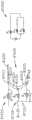
图6为针感测系统的示意图和针感测系统的针感测电路的电路图,其中针感测系统的针处于原始位置;6 is a schematic diagram of a needle sensing system and a circuit diagram of a needle sensing circuit of the needle sensing system, wherein the needle of the needle sensing system is in a home position;
图7为图6的针感测系统的示意图和图6的针感测电路的电路图,其中针处于第一部分击发位置;7 is a schematic diagram of the needle sensing system of FIG. 6 and a circuit diagram of the needle sensing circuit of FIG. 6 with the needle in a first partially fired position;
图8为图6的针感测系统的示意图和图6的针感测电路的电路图,其中针处于第二部分击发位置;8 is a schematic diagram of the needle sensing system of FIG. 6 and a circuit diagram of the needle sensing circuit of FIG. 6 with the needle in a second partially fired position;
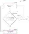
图9为示出用于控制外科缝合器械的控制程序的过程的逻辑图;9 is a logic diagram illustrating a process of a control program for controlling a surgical stapling instrument;
图10为包括自适应针驱动系统的缝合装置仓的平面图;10 is a plan view of a suturing device cartridge including an adaptive needle drive system;
图11为自适应针驱动系统的第一方面的曲线图;11 is a graph of a first aspect of an adaptive needle drive system;
图12为图11的自适应针驱动系统的第二方面的曲线图;12 is a graph of a second aspect of the adaptive needle drive system of FIG. 11;
图13为图11的自适应针驱动系统的第三方面的曲线图;13 is a graph of a third aspect of the adaptive needle drive system of FIG. 11;
图14为包括轴和针驱动系统的可塌缩缝合装置的平面图,其中针驱动系统包括可移动针引导件,并且其中可移动针引导件处于膨胀位置;14 is a plan view of a collapsible stapling device including a shaft and a needle drive system, wherein the needle drive system includes a movable needle guide, and wherein the movable needle guide is in an expanded position;
图15为图14的缝合装置的平面图,其中可移动针引导件处于塌缩位置;Figure 15 is a plan view of the stapling device of Figure 14 with the moveable needle guide in a collapsed position;
图16为图14的缝合装置的平面图,其中可移动针引导件处于部分膨胀位置;Figure 16 is a plan view of the stapling device of Figure 14 with the moveable needle guide in a partially expanded position;
图17为可塌缩缝合装置的平面图,该可塌缩缝合装置包括轴和被配置成能够相对于轴进行关节运动的端部执行器,其中端部执行器包括针驱动系统,该针驱动系统包括可移动针引导件;17 is a plan view of a collapsible stapling device including a shaft and an end effector configured to articulate relative to the shaft, wherein the end effector includes a needle drive system, the needle drive system Includes removable needle guide;
图18为包括针驱动系统的可塌缩缝合装置的平面图,该针驱动系统包括可移动针引导件和中间进给轮;18 is a plan view of a collapsible stapling device including a needle drive system including a movable needle guide and an intermediate feed wheel;
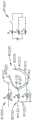
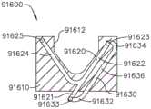
图19为缝合装置的端部执行器的剖视图,该缝合装置包括主体部分、限定在主体部分内的针轨道以及缝合针,其中缝合针处于停止位置;19 is a cross-sectional view of an end effector of a suturing device including a body portion, a needle track defined within the body portion, and a suturing needle with the suturing needle in a rest position;
图20为图19的端部执行器的剖视图,其中缝合针处于准备击发位置;20 is a cross-sectional view of the end effector of FIG. 19 with the suture needle in a ready-to-fire position;
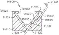
图21为图19的端部执行器的剖视图,其中缝合针处于部分击发位置;Figure 21 is a cross-sectional view of the end effector of Figure 19 with the suture needle in a partially fired position;
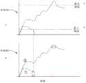
图22为示出在端部执行器的使用期间端部执行器的部件的应力和应变与对应的可识别事件之间的关系的图;22 is a graph showing the relationship between stress and strain of components of the end effector and corresponding identifiable events during use of the end effector;
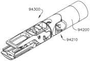
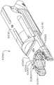
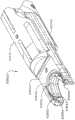
图23为包括致动接口和待用致动接口致动的模块化轴的外科器械系统的局部透视图,其中外科器械系统示出为处于部分附接构型;23 is a partial perspective view of a surgical instrument system including an actuation interface and a modular shaft to be actuated with the actuation interface, wherein the surgical instrument system is shown in a partially attached configuration;
图24为示出图23的外科器械系统的所感测到的扭矩和图23的外科器械系统的马达的所感测到的电流的曲线图;24 is a graph showing sensed torque of the surgical instrument system of FIG. 23 and sensed current of a motor of the surgical instrument system of FIG. 23;
图25为外科抓紧器和单极桥接器械的局部透视图;Figure 25 is a partial perspective view of the surgical grasper and monopolar bridge instrument;
图26为示出图25的外科抓紧器的反应性算法的曲线图;FIG. 26 is a graph illustrating a reactivity algorithm for the surgical grasper of FIG. 25;
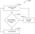
图27为示出用于控制外科器械的控制程序的过程的逻辑图;27 is a logic diagram illustrating a process of a control program for controlling a surgical instrument;
图28为外科缝合器械的局部透视图;并且Figure 28 is a partial perspective view of the surgical stapling instrument; and
图29为示出图28的外科缝合器械的感测参数并且还示出用于外科缝合器械对感测到的参数做出反应的算法的曲线图。29 is a graph showing sensed parameters of the surgical stapling instrument of FIG. 28 and also showing an algorithm for the surgical stapling instrument to react to the sensed parameters.
图30为示出用于控制外科缝合器械的控制程序的过程的逻辑图;30 is a logic diagram illustrating a process of a control program for controlling a surgical stapling instrument;
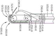
图31为包括缝合线仓的端部执行器组件的透视图;31 is a perspective view of an end effector assembly including a suture cartridge;
图32为图31的端部执行器组件的局部透视图;Figure 32 is a partial perspective view of the end effector assembly of Figure 31;
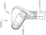
图33为包括针感测系统的端部执行器组件的局部剖视图;33 is a partial cross-sectional view of an end effector assembly including a needle sensing system;
图34为包括针感测系统的端部执行器组件的局部透视图;34 is a partial perspective view of an end effector assembly including a needle sensing system;
图35为包括针感测系统的端部执行器组件的局部透视图;35 is a partial perspective view of an end effector assembly including a needle sensing system;
图36为包括针感测系统的端部执行器组件的局部透视图;36 is a partial perspective view of an end effector assembly including a needle sensing system;
图37为包括针感测系统的端部执行器组件的局部透视图;37 is a partial perspective view of an end effector assembly including a needle sensing system;
图38为与外科缝合器械一起使用的螺旋形缝合针的透视图;Figure 38 is a perspective view of a helical stapling needle for use with a surgical stapling instrument;
图39为图38的螺旋形缝合针的正视图;Figure 39 is a front view of the helical suture needle of Figure 38;
图40为示出用于控制外科器械的控制程序的过程的逻辑流程图;40 is a logic flow diagram illustrating a process of a control program for controlling a surgical instrument;
图41为包括马达的外科缝合器械柄部的透视图;41 is a perspective view of a surgical stapling instrument handle including a motor;
图42为图41的外科缝合器械柄部的局部剖视图;Figure 42 is a partial cross-sectional view of the handle of the surgical stapling instrument of Figure 41;
图43为与外科缝合系统一起使用的缝合仓的分解图;Figure 43 is an exploded view of a suturing cartridge for use with a surgical suturing system;
图44为根据至少一个实施方案的包括能够抓紧和解剖的钳口组件的外科器械的局部剖视图;44 is a partial cross-sectional view of a surgical instrument including a jaw assembly capable of grasping and dissecting, according to at least one embodiment;
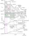
图45为根据至少一个实施方案的示出图44的钳口组件的力、速度和取向的曲线图;Figure 45 is a graph showing force, velocity and orientation of the jaw assembly of Figure 44, according to at least one embodiment;
图46为用于切割组织的双极夹钳的局部透视图;Figure 46 is a partial perspective view of a bipolar clamp for cutting tissue;
图47为图46的双极夹钳的透视图;Figure 47 is a perspective view of the bipolar clamp of Figure 46;
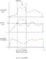
图48为根据至少一个实施方案的示出图46的双极夹钳的钳口的力和速度的曲线图;Figure 48 is a graph showing force and velocity of the jaws of the bipolar clamp of Figure 46, according to at least one embodiment;
图49为根据至少一个实施方案的示出图46的双极夹钳的操作的另一曲线图;并且Figure 49 is another graph illustrating operation of the bipolar clamp of Figure 46, according to at least one embodiment; and
图50为与本文所公开的任何外科器械一起使用的控制系统的示意图。50 is a schematic diagram of a control system for use with any of the surgical instruments disclosed herein.
在所述若干视图中,对应的参考符号指示对应的部件。本文所述的范例以一种形式示出了本发明的各种实施方案,且这种范例不应被解释为以任何方式限制本发明的范围。Corresponding reference characters indicate corresponding parts throughout the several views. The exemplifications described herein illustrate various embodiments of the invention in one form, and such exemplifications should not be construed to limit the scope of the invention in any way.
具体实施方式Detailed ways
本申请的申请人拥有于2018年8月24日提交且各自全文以引用方式并入本文的以下美国专利申请:The applicant of the present application has the following US patent applications filed on August 24, 2018, each of which is incorporated herein by reference in its entirety:
-名称为“SURGICAL SUTURING INSTRUMENT CONFIGURED TO MANIPULATE TISSUEUSING MECHANICAL AND ELECTRICAL POWER”的美国专利申请序列号16/112,129;- US Patent Application Serial No. 16/112,129 entitled "SURGICAL SUTURING INSTRUMENT CONFIGURED TO MANIPULATE TISSUEUSING MECHANICAL AND ELECTRICAL POWER";
-名称为“SURGICAL SUTURING INSTRUMENT COMPRISING A CAPTURE WIDTH WHICHIS LARGER THAN TROCAR DIAMETER”的美国专利申请序列号16/112,155;- US Patent Application Serial No. 16/112,155 entitled "SURGICAL SUTURING INSTRUMENT COMPRISING A CAPTURE WIDTH WHICHIS LARGER THAN TROCAR DIAMETER";
-名称为“SURGICAL SUTURING INSTRUMENT COMPRISING A NON-CIRCULARNEEDLE”的美国专利申请序列号16/112,168;- US Patent Application Serial No. 16/112,168 entitled "SURGICAL SUTURING INSTRUMENT COMPRISING A NON-CIRCULARNEEDLE";
-名称为“REACTIVE ALGORITHM FOR SURGICAL SYSTEM”的美国专利申请序列号16/112,193;- US Patent Application Serial No. 16/112,193 entitled "REACTIVE ALGORITHM FOR SURGICAL SYSTEM";
-名称为“SURGICAL INSTRUMENT COMPRISING AN ADAPTIVE ELECTRICAL SYSTEM”的美国专利申请序列号16/112,099;- US Patent Application Serial No. 16/112,099 entitled "SURGICAL INSTRUMENT COMPRISING AN ADAPTIVE ELECTRICAL SYSTEM";
-名称为“CONTROL SYSTEM ARRANGEMENTS FOR A MODULAR SURGICALINSTRUMENT”的美国专利申请序列号16/112,112;- US Patent Application Serial No. 16/112,112 entitled "CONTROL SYSTEM ARRANGEMENTS FOR A MODULAR SURGICALINSTRUMENT";
-名称为“ADAPTIVE CONTROL PROGRAMS FOR A SURGICAL SYSTEM COMPRISINGMORE THAN ONE TYPE OF CARTRIDGE”的美国专利申请序列号16/112,119;- US Patent Application Serial No. 16/112,119 entitled "ADAPTIVE CONTROL PROGRAMS FOR A SURGICAL SYSTEM COMPRISINGMORE THAN ONE TYPE OF CARTRIDGE";
-名称为“SURGICAL INSTRUMENT SYSTEMS COMPRISING BATTERY ARRANGEMENTS”的美国专利申请序列号16/112,097;- US Patent Application Serial No. 16/112,097 entitled "SURGICAL INSTRUMENT SYSTEMS COMPRISING BATTERY ARRANGEMENTS";
-名称为“SURGICAL INSTRUMENT SYSTEMS COMPRISING HANDLE ARRANGEMENTS”的美国专利申请序列号16/112,109;- US Patent Application Serial No. 16/112,109 entitled "SURGICAL INSTRUMENT SYSTEMS COMPRISING HANDLE ARRANGEMENTS";
-名称为“SURGICAL INSTRUMENT SYSTEMS COMPRISING FEEDBACK MECHANISMS”的美国专利申请序列号16/112,114;- US Patent Application Serial No. 16/112,114 entitled "SURGICAL INSTRUMENT SYSTEMS COMPRISING FEEDBACK MECHANISMS";
-名称为“SURGICAL INSTRUMENT SYSTEMS COMPRISING LOCKOUT MECHANISMS”的美国专利申请序列号16/112,117;- US Patent Application Serial No. 16/112,117 entitled "SURGICAL INSTRUMENT SYSTEMS COMPRISING LOCKOUT MECHANISMS";
-名称为“SURGICAL INSTRUMENTS COMPRISING A LOCKABLE END EFFECTORSOCKET”的美国专利申请序列号16/112,095;- US Patent Application Serial No. 16/112,095 entitled "SURGICAL INSTRUMENTS COMPRISING A LOCKABLE END EFFECTORSOCKET";
-名称为“SURGICAL INSTRUMENTS COMPRISING A SHIFTING MECHANISM”的美国专利申请序列号16/112,121;- US Patent Application Serial No. 16/112,121 entitled "SURGICAL INSTRUMENTS COMPRISING A SHIFTING MECHANISM";
-名称为“SURGICAL INSTRUMENTS COMPRISING A SYSTEM FOR ARTICULATION ANDROTATION COMPENSATION”的美国专利申请序列号16/112,151;- US Patent Application Serial No. 16/112,151 entitled "SURGICAL INSTRUMENTS COMPRISING A SYSTEM FOR ARTICULATION ANDROTATION COMPENSATION";
-名称为“SURGICAL INSTRUMENTS COMPRISING A BIASED SHIFTING MECHANISM”的美国专利申请序列号16/112,154;- US Patent Application Serial No. 16/112,154 entitled "SURGICAL INSTRUMENTS COMPRISING A BIASED SHIFTING MECHANISM";
-名称为“SURGICAL INSTRUMENTS COMPRISING A SHIFTING MECHANISM”的美国专利申请序列号16/112,226;- US Patent Application Serial No. 16/112,226 entitled "SURGICAL INSTRUMENTS COMPRISING A SHIFTING MECHANISM";
-名称为“SURGICAL DISSECTORS AND MANUFACTURING TECHNIQUES”的美国专利申请序列号16112062;- US Patent Application Serial No. 16112062 entitled "SURGICAL DISSECTORS AND MANUFACTURING TECHNIQUES";
-名称为“SURGICAL DISSECTORS CONFIGURED TO APPLY MECHANICAL ANDELECTRICAL ENERGY”的美国专利申请序列号16/112,098;- US Patent Application Serial No. 16/112,098 entitled "SURGICAL DISSECTORS CONFIGURED TO APPLY MECHANICAL ANDELECTRICAL ENERGY";
-名称为“SURGICAL CLIP APPLIER CONFIGURED TO STORE CLIPS IN A STOREDSTATE”的美国专利申请序列号16/112,237;- US Patent Application Serial No. 16/112,237 entitled "SURGICAL CLIP APPLIER CONFIGURED TO STORE CLIPS IN A STOREDSTATE";
-名称为“SURGICAL CLIP APPLIER COMPRISING AN EMPTY CLIP CARTRIDGELOCKOUT”的美国专利申请序列号16/112,245;- US Patent Application Serial No. 16/112,245 entitled "SURGICAL CLIP APPLIER COMPRISING AN EMPTY CLIP CARTRIDGELOCKOUT";
-名称为“SURGICAL CLIP APPLIER COMPRISING AN AUTOMATIC CLIP FEEDINGSYSTEM”的美国专利申请序列号16/112,249;- US Patent Application Serial No. 16/112,249 entitled "SURGICAL CLIP APPLIER COMPRISING AN AUTOMATIC CLIP FEEDINGSYSTEM";
-名称为“SURGICAL CLIP APPLIER COMPRISING ADAPTIVE FIRING CONTROL”的美国专利申请序列号16/112,253;并且- US Patent Application Serial No. 16/112,253 entitled "SURGICAL CLIP APPLIER COMPRISING ADAPTIVE FIRING CONTROL"; and
-名称为“SURGICAL CLIP APPLIER COMPRISING ADAPTIVE CONTROL IN RESPONSETO A STRAIN GAUGE CIRCUIT”的美国专利申请序列号16/112,257;- US Patent Application Serial No. 16/112,257 entitled "SURGICAL CLIP APPLIER COMPRISING ADAPTIVE CONTROL IN RESPONSETO A STRAIN GAUGE CIRCUIT";
本申请的申请人拥有于2018年5月1日提交且各自全文以引用方式并入本文的以下美国专利申请:The applicant of the present application has the following US patent applications filed on May 1, 2018, each of which is incorporated herein by reference in its entirety:
-名称为“SURGICAL SUTURING SYSTEMS”的美国临时专利申请序列号62/665,129;- US Provisional Patent Application Serial No. 62/665,129 entitled "SURGICAL SUTURING SYSTEMS";
-名称为“SURGICAL INSTRUMENTS COMPRISING CONTROL SYSTEMS”的美国临时专利申请序列号62/665,139;- US Provisional Patent Application Serial No. 62/665,139 entitled "SURGICAL INSTRUMENTS COMPRISING CONTROL SYSTEMS";
-名称为“SURGICAL INSTRUMENTS COMPRISING HANDLE ARRANGEMENTS”的美国临时专利申请序列号62/665,177;- US Provisional Patent Application Serial No. 62/665,177 entitled "SURGICAL INSTRUMENTS COMPRISING HANDLE ARRANGEMENTS";
-名称为“MODULAR SURGICAL INSTRUMENTS”的美国临时专利申请序列号62/665,128;- US Provisional Patent Application Serial No. 62/665,128 entitled "MODULAR SURGICAL INSTRUMENTS";
-名称为“SURGICAL DISSECTORS”的美国临时专利申请序列号62/665,192;并且- US Provisional Patent Application Serial No. 62/665,192 entitled "SURGICAL DISSECTORS"; and
-名称为“SURGICAL CLIP APPLIER”的美国临时专利申请序列号62/665,134;- US Provisional Patent Application Serial No. 62/665,134 entitled "SURGICAL CLIP APPLIER";
本申请的申请人拥有于2018年2月28日提交且各自全文以引用方式并入本文的以下美国专利申请:The applicant of the present application has the following US patent applications filed on February 28, 2018, each of which is incorporated herein by reference in its entirety:
-名称为“SURGICAL INSTRUMENT WITH REMOTE RELEASE”的美国专利申请序列号15/908,021;- US Patent Application Serial No. 15/908,021 entitled "SURGICAL INSTRUMENT WITH REMOTE RELEASE";
-名称为“SURGICAL INSTRUMENT HAVING DUAL ROTATABLE MEMBERS TO EFFECTDIFFERENT TYPES OF END EFFECTOR MOVEMENT”的美国专利申请序列号15/908,012;- US Patent Application Serial No. 15/908,012 entitled "SURGICAL INSTRUMENT HAVING DUAL ROTATABLE MEMBERS TO EFFECTDIFFERENT TYPES OF END EFFECTOR MOVEMENT";
-名称为“SURGICAL INSTRUMENT WITH ROTARY DRIVE SELECTIVELY ACTUATINGMULTIPLE END EFFECTOR FUNCTIONS”的美国专利申请序列号15/908,040;- US Patent Application Serial No. 15/908,040 entitled "SURGICAL INSTRUMENT WITH ROTARY DRIVE SELECTIVELY ACTUATINGMULTIPLE END EFFECTOR FUNCTIONS";
-名称为“SURGICAL INSTRUMENT WITH ROTARY DRIVE SELECTIVELY ACTUATINGMULTIPLE END EFFECTOR FUNCTIONS”的美国专利申请序列号15/908,057;- US Patent Application Serial No. 15/908,057 entitled "SURGICAL INSTRUMENT WITH ROTARY DRIVE SELECTIVELY ACTUATINGMULTIPLE END EFFECTOR FUNCTIONS";
-名称为“SURGICAL INSTRUMENT WITH MODULAR POWER SOURCES”的美国专利申请序列号15/908,058;并且- US Patent Application Serial No. 15/908,058 entitled "SURGICAL INSTRUMENT WITH MODULAR POWER SOURCES"; and
-名称为“SURGICAL INSTRUMENT WITH SENSOR AND/OR CONTROL SYSTEMS”的美国专利申请序列号15/908,143;- US Patent Application Serial No. 15/908,143 entitled "SURGICAL INSTRUMENT WITH SENSOR AND/OR CONTROL SYSTEMS";
本申请的申请人拥有于2017年10月30日提交且各自全文以引用方式并入本文的以下美国专利申请:The applicant of the present application has the following US patent applications filed on October 30, 2017, each of which is incorporated herein by reference in its entirety:
-名称为“SURGICAL INSTRUMENT WITH REMOTE RELEASE”的美国临时专利申请序列号62/578,793;- US Provisional Patent Application Serial No. 62/578,793 entitled "SURGICAL INSTRUMENT WITH REMOTE RELEASE";
-名称为“SURGICAL INSTRUMENT HAVING DUAL ROTATABLE MEMBERS TO EFFECTDIFFERENT TYPES OF END EFFECTOR MOVEMENT”的美国临时专利申请序列号62/578,804;- U.S. Provisional Patent Application Serial No. 62/578,804 entitled "SURGICAL INSTRUMENT HAVING DUAL ROTATABLE MEMBERS TO EFFECTDIFFERENT TYPES OF END EFFECTOR MOVEMENT";
-名称为“SURGICAL INSTRUMENT WITH ROTARY DRIVE SELECTIVELY ACTUATINGMULTIPLE END EFFECTOR FUNCTIONS”的美国临时专利申请序列号62/578,817;- U.S. Provisional Patent Application Serial No. 62/578,817 entitled "SURGICAL INSTRUMENT WITH ROTARY DRIVE SELECTIVELY ACTUATINGMULTIPLE END EFFECTOR FUNCTIONS";
-名称为“SURGICAL INSTRUMENT WITH ROTARY DRIVE SELECTIVELY ACTUATINGMULTIPLE END EFFECTOR FUNCTIONS”的美国临时专利申请序列号62/578,835;- US Provisional Patent Application Serial No. 62/578,835 entitled "SURGICAL INSTRUMENT WITH ROTARY DRIVE SELECTIVELY ACTUATINGMULTIPLE END EFFECTOR FUNCTIONS";
-名称为“SURGICAL INSTRUMENT WITH MODULAR POWER SOURCES”的美国临时专利申请序列号62/578,844;并且- U.S. Provisional Patent Application Serial No. 62/578,844 entitled "SURGICAL INSTRUMENT WITH MODULAR POWER SOURCES"; and
-名称为“SURGICAL INSTRUMENT WITH SENSOR AND/OR CONTROL SYSTEMS”的美国临时专利申请序列号62/578,855;- U.S. Provisional Patent Application Serial No. 62/578,855 entitled "SURGICAL INSTRUMENT WITH SENSOR AND/OR CONTROL SYSTEMS";
本专利申请的申请人拥有于2017年12月28日提交的以下美国临时专利申请,其中的每个的公开内容以引用方式全文并入本文:The applicant of this patent application has the following U.S. Provisional Patent Applications filed on December 28, 2017, the disclosures of each of which are incorporated herein by reference in their entirety:
-名称为“INTERACTIVE SURGICAL PLATFORM”的美国临时专利申请序列号62/611,341;- US Provisional Patent Application Serial No. 62/611,341 entitled "INTERACTIVE SURGICAL PLATFORM";
-名称为“CLOUD-BASED MEDICAL ANALYTICS”的美国临时专利申请序列号62/611,340;并且- US Provisional Patent Application Serial No. 62/611,340 entitled "CLOUD-BASED MEDICAL ANALYTICS"; and
-名称为“ROBOT ASSISTED SURGICAL PLATFORM”的美国临时专利申请序列号62/611,339;- US Provisional Patent Application Serial No. 62/611,339 entitled "ROBOT ASSISTED SURGICAL PLATFORM";
本专利申请的申请人拥有于2018年3月28日提交的以下美国临时专利申请,其中的每个以引用方式全文并入本文:The applicant of this patent application has the following U.S. Provisional Patent Applications filed on March 28, 2018, each of which is incorporated herein by reference in its entirety:
-名称为“INTERACTIVE SURGICAL SYSTEMS WITH ENCRYPTED COMMUNICATIONCAPABILITIES”的美国临时专利申请序列号62/649,302;- US Provisional Patent Application Serial No. 62/649,302 entitled "INTERACTIVE SURGICAL SYSTEMS WITH ENCRYPTED COMMUNICATIONCAPABILITIES";
-名称为“DATA STRIPPING METHOD TO INTERROGATE PATIENT RECORDS ANDCREATE ANONYMIZED RECORD”的美国临时专利申请序列号62/649,294;- US Provisional Patent Application Serial No. 62/649,294 entitled "DATA STRIPPING METHOD TO INTERROGATE PATIENT RECORDS ANDCREATE ANONYMIZED RECORD";
-名称为“SURGICAL HUB SITUATIONAL AWARENESS”的美国临时专利申请序列号62/649,300;- US Provisional Patent Application Serial No. 62/649,300 entitled "SURGICAL HUB SITUATIONAL AWARENESS";
-名称为“SURGICAL HUB SPATIAL AWARENESS TO DETERMINE DEVICES INOPERATING THEATER”的美国临时专利申请序列号62/649,309;- US Provisional Patent Application Serial No. 62/649,309 entitled "SURGICAL HUB SPATIAL AWARENESS TO DETERMINE DEVICES INOPERATING THEATER";
-名称为“COMPUTER IMPLEMENTED INTERACTIVE SURGICAL SYSTEMS”的美国临时专利申请序列号62/649,310;- US Provisional Patent Application Serial No. 62/649,310 entitled "COMPUTER IMPLEMENTED INTERACTIVE SURGICAL SYSTEMS";
-名称为“USE OF LASER LIGHT AND RED-GREEN-BLUE COLORATION TO DETERMINEPROPERTIES OF BACK SCATTERED LIGHT”的美国临时专利申请序列号62/649,291;- US Provisional Patent Application Serial No. 62/649,291 entitled "USE OF LASER LIGHT AND RED-GREEN-BLUE COLORATION TO DETERMINEPROPERTIES OF BACK SCATTERED LIGHT";
-名称为“ADAPTIVE CONTROL PROGRAM UPDATES FOR SURGICAL DEVICES”的美国临时专利申请序列号62/649,296;- U.S. Provisional Patent Application Serial No. 62/649,296 entitled "ADAPTIVE CONTROL PROGRAM UPDATES FOR SURGICAL DEVICES";
-名称为“CLOUD-BASED MEDICAL ANALYTICS FOR CUSTOMIZATION ANDRECOMMENDATIONS TO A USER”的美国临时专利申请序列号62/649,333;- US Provisional Patent Application Serial No. 62/649,333 entitled "CLOUD-BASED MEDICAL ANALYTICS FOR CUSTOMIZATION ANDRECOMMENDATIONS TO A USER";
-名称为“CLOUD-BASED MEDICAL ANALYTICS FOR SECURITY AND AUTHENTICATIONTRENDS AND REACTIVE MEASURES”的美国临时专利申请序列号62/649,327;- US Provisional Patent Application Serial No. 62/649,327 entitled "CLOUD-BASED MEDICAL ANALYTICS FOR SECURITY AND AUTHENTICATION TRENDS AND REACTIVE MEASURES";
-名称为“DATA HANDLING AND PRIORITIZATION IN A CLOUD ANALYTICSNETWORK”的美国临时专利申请序列号62/649,315;- US Provisional Patent Application Serial No. 62/649,315 entitled "DATA HANDLING AND PRIORITIZATION IN A CLOUD ANALYTICSNETWORK";
-名称为“CLOUD INTERFACE FOR COUPLED SURGICAL DEVICES”的美国临时专利申请序列号62/649,313;- US Provisional Patent Application Serial No. 62/649,313 entitled "CLOUD INTERFACE FOR COUPLED SURGICAL DEVICES";
-名称为“DRIVE ARRANGEMENTS FOR ROBOT-ASSISTED SURGICAL PLATFORMS”的美国临时专利申请序列号62/649,320;- US Provisional Patent Application Serial No. 62/649,320 entitled "DRIVE ARRANGEMENTS FOR ROBOT-ASSISTED SURGICAL PLATFORMS";
-名称为“AUTOMATIC TOOL ADJUSTMENTS FOR ROBOT-ASSISTED SURGICALPLATFORMS”的美国临时专利申请序列号62/649,307;并且- US Provisional Patent Application Serial No. 62/649,307 entitled "AUTOMATIC TOOL ADJUSTMENTS FOR ROBOT-ASSISTED SURGICAL PLATFORMS"; and
-名称为“SENSING ARRANGEMENTS FOR ROBOT-ASSISTED SURGICAL PLATFORMS”的美国临时专利申请序列号62/649,323;- US Provisional Patent Application Serial No. 62/649,323 entitled "SENSING ARRANGEMENTS FOR ROBOT-ASSISTED SURGICAL PLATFORMS";
本专利申请的申请人拥有于2018年3月29日提交的以下美国专利申请,其中的每个以引用方式全文并入本文:The applicant of this patent application has the following US patent applications filed on March 29, 2018, each of which is incorporated herein by reference in its entirety:
-名称为“INTERACTIVE SURGICAL SYSTEMS WITH ENCRYPTED COMMUNICATIONCAPABILITIES”的美国专利申请序列号15/940,641;- US Patent Application Serial No. 15/940,641 entitled "INTERACTIVE SURGICAL SYSTEMS WITH ENCRYPTED COMMUNICATIONCAPABILITIES";
-名称为“INTERACTIVE SURGICAL SYSTEMS WITH CONDITION HANDLING OFDEVICES AND DATA CAPABILITIES”的美国专利申请序列号15/940,648;- US Patent Application Serial No. 15/940,648 entitled "INTERACTIVE SURGICAL SYSTEMS WITH CONDITION HANDLING OFDEVICES AND DATA CAPABILITIES";
-名称为“SURGICAL HUB COORDINATION OF CONTROL AND COMMUNICATION OFOPERATING ROOM DEVICES”的美国专利申请序列号15/940,656;- US Patent Application Serial No. 15/940,656 entitled "SURGICAL HUB COORDINATION OF CONTROL AND COMMUNICATION OFOPERATING ROOM DEVICES";
-名称为“SPATIAL AWARENESS OF SURGICAL HUBS IN operating ROOMS”的美国专利申请序列号15/940,666;- US Patent Application Serial No. 15/940,666 entitled "SPATIAL AWARENESS OF SURGICAL HUBS IN operating ROOMS";
-名称为“COOPERATIVE UTILIZATION OF DATA DERIVED FROM secondarySOURCES BY INTELLIGENT SURGICAL HUBS”的美国专利申请序列号15/940,670;- US Patent Application Serial No. 15/940,670 entitled "COOPERATIVE UTILIZATION OF DATA DERIVED FROM secondarySOURCES BY INTELLIGENT SURGICAL HUBS";
-名称为“SURGICAL HUB CONTROL ARRANGEMENTS”的美国专利申请序列号15/940,677;- US Patent Application Serial No. 15/940,677 entitled "SURGICAL HUB CONTROL ARRANGEMENTS";
-名称为“DATA STRIPPING METHOD TO INTERROGATE PATIENT RECORDS ANDCREATE ANONYMIZED RECORD”的美国专利申请序列号15/940,632;- US Patent Application Serial No. 15/940,632 entitled "DATA STRIPPING METHOD TO INTERROGATE PATIENT RECORDS ANDCREATE ANONYMIZED RECORD";
-名称为“COMMUNICATION HUB AND STORAGE DEVICE FOR STORING PARAMETERSAND STATUS OF A SURGICAL DEVICE TO BE SHARED WITH CLOUD BASED ANALYTICSSYSTEMS”的美国专利申请序列号15/940,640;- US Patent Application Serial No. 15/940,640 entitled "COMMUNICATION HUB AND STORAGE DEVICE FOR STORING PARAMETERSAND STATUS OF A SURGICAL DEVICE TO BE SHARED WITH CLOUD BASED ANALYTICSSYSTEMS";
-名称为“SELF DESCRIBING DATA PACKETS GENERATED AT AN ISSUINGINSTRUMENT”的美国专利申请序列号15/940,645;- US Patent Application Serial No. 15/940,645 entitled "SELF DESCRIBING DATA PACKETS GENERATED AT AN ISSUINGINSTRUMENT";
-名称为“DATA PAIRING TO INTERCONNECT A DEVICE MEASURED PARAMETER WITHAN OUTCOME”的美国专利申请序列号15/940,649;- US Patent Application Serial No. 15/940,649 entitled "DATA PAIRING TO INTERCONNECT A DEVICE MEASURED PARAMETER WITHAN OUTCOME";
-名称为“SURGICAL HUB SITUATIONAL AWARENESS”的美国专利申请序列号15/940,654;- US Patent Application Serial No. 15/940,654 entitled "SURGICAL HUB SITUATIONAL AWARENESS";
-名称为“SURGICAL SYSTEM DISTRIBUTED PROCESSING”的美国专利申请序列号15/940,663;- US Patent Application Serial No. 15/940,663 entitled "SURGICAL SYSTEM DISTRIBUTED PROCESSING";
-名称为“AGGREGATION AND REPORTING OF SURGICAL HUB DATA”的美国专利申请序列号15/940,668;- US Patent Application Serial No. 15/940,668 entitled "AGGREGATION AND REPORTING OF SURGICAL HUB DATA";
-名称为“SURGICAL HUB SPATIAL AWARENESS TO DETERMINE DEVICES INOPERATING THEATER”的美国专利申请序列号15/940,671;- US Patent Application Serial No. 15/940,671 entitled "SURGICAL HUB SPATIAL AWARENESS TO DETERMINE DEVICES INOPERATING THEATER";
-名称为“DISPLAY OF ALIGNMENT OF STAPLE CARTRIDGE TO PRIOR LINEARSTAPLE LINE”的美国专利申请序列号15/940,686;- US Patent Application Serial No. 15/940,686 entitled "DISPLAY OF ALIGNMENT OF STAPLE CARTRIDGE TO PRIOR LINEARSTAPLE LINE";
-名称为“STERILE FIELD INTERACTIVE CONTROL DISPLAYS”的美国专利申请序列号15/940,700;- US Patent Application Serial No. 15/940,700 entitled "STERILE FIELD INTERACTIVE CONTROL DISPLAYS";
-名称为“COMPUTER IMPLEMENTED INTERACTIVE SURGICAL SYSTEMS”的美国专利申请序列号15/940,629。- US Patent Application Serial No. 15/940,629 entitled "COMPUTER IMPLEMENTED INTERACTIVE SURGICAL SYSTEMS".
-名称为“USE OF LASER LIGHT AND RED-GREEN-BLUE COLORATION TO DETERMINEPROPERTIES OF BACK SCATTERED LIGHT”的美国专利申请序列号15/940,704;- US Patent Application Serial No. 15/940,704 entitled "USE OF LASER LIGHT AND RED-GREEN-BLUE COLORATION TO DETERMINEPROPERTIES OF BACK SCATTERED LIGHT";
-名称为“CHARACTERIZATION OF TISSUE IRREGULARITIES THROUGH THE USE OFMONO-CHROMATIC LIGHT REFRACTIVITY”的美国专利申请序列号15/940,722;并且- US Patent Application Serial No. 15/940,722 entitled "CHARACTERIZATION OF TISSUE IRREGULARITIES THROUGH THE USE OFMONO-CHROMATIC LIGHT REFRACTIVITY"; and
-名称为“DUAL CMOS ARRAY IMAGING”的美国专利申请序列号15/940,742;- US Patent Application Serial No. 15/940,742 entitled "DUAL CMOS ARRAY IMAGING";
本专利申请的申请人拥有于2018年3月29日提交的以下美国专利申请,其中的每个以引用方式全文并入本文:The applicant of this patent application has the following US patent applications filed on March 29, 2018, each of which is incorporated herein by reference in its entirety:
-名称为“ADAPTIVE CONTROL PROGRAM UPDATES FOR SURGICAL DEVICES”的美国专利申请序列号15/940,636;- US Patent Application Serial No. 15/940,636 entitled "ADAPTIVE CONTROL PROGRAM UPDATES FOR SURGICAL DEVICES";
-名称为“ADAPTIVE CONTROL PROGRAM UPDATES FOR SURGICAL HUBS”的美国专利申请序列号15/940,653;- US Patent Application Serial No. 15/940,653 entitled "ADAPTIVE CONTROL PROGRAM UPDATES FOR SURGICAL HUBS";
-名称为“CLOUD-BASED MEDICAL ANALYTICS FOR CUSTOMIZATION ANDRECOMMENDATIONS TO A USER”的美国专利申请序列号15/940,660;- US Patent Application Serial No. 15/940,660 entitled "CLOUD-BASED MEDICAL ANALYTICS FOR CUSTOMIZATION ANDRECOMMENDATIONS TO A USER";
-名称为“CLOUD-BASED MEDICAL ANALYTICS FOR LINKING OF LOCAL USAGETRENDS WITH THE RESOURCE ACQUISITION BEHAVIORS OF LARGER DATA SET”的美国专利申请序列号15/940,679;- US Patent Application Serial No. 15/940,679 entitled "CLOUD-BASED MEDICAL ANALYTICS FOR LINKING OF LOCAL USAGETRENDS WITH THE RESOURCE ACQUISITION BEHAVIORS OF LARGER DATA SET";
-名称为“CLOUD-BASED MEDICAL ANALYTICS FOR MEDICAL FACILITY SEGMENTEDINDIVIDUALIZATION OF INSTRUMENT FUNCTION”的美国专利申请序列号15/940,694;- US Patent Application Serial No. 15/940,694 entitled "CLOUD-BASED MEDICAL ANALYTICS FOR MEDICAL FACILITY SEGMENTEDINDIVIDUALIZATION OF INSTRUMENT FUNCTION";
-名称为“CLOUD-BASED MEDICAL ANALYTICS FOR SECURITY AND AUTHENTICATIONTRENDS AND REACTIVE MEASURES”的美国专利申请序列号15/940,634;- US Patent Application Serial No. 15/940,634 entitled "CLOUD-BASED MEDICAL ANALYTICS FOR SECURITY AND AUTHENTICATION TRENDS AND REACTIVE MEASURES";
-名称为“DATA HANDLING AND PRIORITIZATION IN A CLOUD ANALYTICSNETWORK”的美国专利申请序列号15/940,706;并且- US Patent Application Serial No. 15/940,706 entitled "DATA HANDLING AND PRIORITIZATION IN A CLOUD ANALYTICSNETWORK"; and
-名称为“CLOUD INTERFACE FOR COUPLED SURGICAL DEVICES”的美国专利申请序列号15/940,675。- US Patent Application Serial No. 15/940,675 entitled "CLOUD INTERFACE FOR COUPLED SURGICAL DEVICES".
本专利申请的申请人拥有于2018年3月29日提交的以下美国专利申请,其中的每个以引用方式全文并入本文:The applicant of this patent application has the following US patent applications filed on March 29, 2018, each of which is incorporated herein by reference in its entirety:
-名称为“DRIVE ARRANGEMENTS FOR ROBOT-ASSISTED SURGICAL PLATFORMS”的美国专利申请序列号15/940,627;- US Patent Application Serial No. 15/940,627 entitled "DRIVE ARRANGEMENTS FOR ROBOT-ASSISTED SURGICAL PLATFORMS";
-名称为“COMMUNICATION ARRANGEMENTS FOR ROBOT-ASSISTED SURGICALPLATFORMS”的美国专利申请序列号15/940,637;- US Patent Application Serial No. 15/940,637 entitled "COMMUNICATION ARRANGEMENTS FOR ROBOT-ASSISTED SURGICAL PLATFORMS";
-名称为“CONTROLS FOR ROBOT-ASSISTED SURGICAL PLATFORMS”的美国专利申请序列号15/940,642;- US Patent Application Serial No. 15/940,642 entitled "CONTROLS FOR ROBOT-ASSISTED SURGICAL PLATFORMS";
-名称为“AUTOMATIC TOOL ADJUSTMENTS FOR ROBOT-ASSISTED SURGICALPLATFORMS”的美国专利申请序列号15/940,676;- US Patent Application Serial No. 15/940,676 entitled "AUTOMATIC TOOL ADJUSTMENTS FOR ROBOT-ASSISTED SURGICAL PLATFORMS";
-名称为“CONTROLLERS FOR ROBOT-ASSISTED SURGICAL PLATFORMS”的美国专利申请序列号15/940,680;- US Patent Application Serial No. 15/940,680 entitled "CONTROLLERS FOR ROBOT-ASSISTED SURGICAL PLATFORMS";
-名称为“COOPERATIVE SURGICAL ACTIONS FOR ROBOT-ASSISTED SURGICALPLATFORMS”的美国专利申请序列号15/940,683;- US Patent Application Serial No. 15/940,683 entitled "COOPERATIVE SURGICAL ACTIONS FOR ROBOT-ASSISTED SURGICAL PLATFORMS";
-名称为“DISPLAY ARRANGEMENTS FOR ROBOT-ASSISTED SURGICAL PLATFORMS”的美国专利申请序列号15/940,690;并且- US Patent Application Serial No. 15/940,690 entitled "DISPLAY ARRANGEMENTS FOR ROBOT-ASSISTED SURGICAL PLATFORMS"; and
-名称为“SENSING ARRANGEMENTS FOR ROBOT-ASSISTED SURGICAL PLATFORMS”的美国专利申请序列号15/940,711;- US Patent Application Serial No. 15/940,711 entitled "SENSING ARRANGEMENTS FOR ROBOT-ASSISTED SURGICAL PLATFORMS";
本专利申请的申请人拥有于2018年3月30日提交的以下美国临时专利申请,其中的每个以引用方式全文并入本文:The applicant of this patent application has the following U.S. Provisional Patent Applications filed on March 30, 2018, each of which is incorporated herein by reference in its entirety:
-名称为“SURGICAL SYSTEMS WITH OPTIMIZED SENSING CAPABILITIES”的美国临时专利申请序列号62/650,887;- US Provisional Patent Application Serial No. 62/650,887 entitled "SURGICAL SYSTEMS WITH OPTIMIZED SENSING CAPABILITIES";
-名称为“SURGICAL SMOKE EVACUATION SENSING AND CONTROLS”的美国专利申请序列号62/650,877;- US Patent Application Serial No. 62/650,877 entitled "SURGICAL SMOKE EVACUATION SENSING AND CONTROLS";
-名称为“SMOKE EVACUATION MODULE FOR INTERACTIVE SURGICAL PLATFORM”的美国专利申请序列号62/650,882;并且- US Patent Application Serial No. 62/650,882 entitled "SMOKE EVACUATION MODULE FOR INTERACTIVE SURGICAL PLATFORM"; and
-名称为“CAPACITIVE COUPLED RETURN PATH PAD WITH SEPARABLE ARRAYELEMENTS”的美国临时专利申请序列号62/650,898;- US Provisional Patent Application Serial No. 62/650,898 entitled "CAPACITIVE COUPLED RETURN PATH PAD WITH SEPARABLE ARRAYELEMENTS";
本专利申请的申请人拥有于2018年4月19日提交的以下美国临时专利申请,其全文以引用方式并入本文:The applicant of this patent application has the following U.S. Provisional Patent Application filed on April 19, 2018, which is incorporated herein by reference in its entirety:
-名称为“METHOD OF HUB COMMUNICATION”的美国临时专利申请序列号62/659,900;- US Provisional Patent Application Serial No. 62/659,900 entitled "METHOD OF HUB COMMUNICATION";
本文列出了许多具体细节,以提供对说明书中所述和附图中所示的实施方案的整体结构、功能、制造和用途的透彻理解。没有详细描述熟知的操作、部件和元件,以免使说明书中描述的实施方案模糊不清。读者将会理解,本文所述和所示的实施方案为非限制性示例,从而可认识到,本文所公开的特定结构和功能细节可为代表性和例示性的。在不脱离权利要求的范围的情况下,可对这些实施方案进行变型和改变。Numerous specific details are set forth herein in order to provide a thorough understanding of the general structure, function, manufacture, and use of the embodiments described in the specification and shown in the accompanying drawings. Well-known operations, components and elements have not been described in detail so as not to obscure the embodiments described in the specification. The reader will understand that the embodiments described and illustrated herein are by way of non-limiting example, so that the specific structural and functional details disclosed herein may be representative and illustrative, and may be appreciated. Variations and changes may be made to these embodiments without departing from the scope of the claims.
术语“包括(comprise)”(以及“包括(comprise)”的任何形式,诸如“包括(comprises)”和“包括(comprising)”)、“具有(have)”(以及“具有(have)”的任何形式,诸如“具有(has)”和“具有(having)”)、“包含(include)”(以及“包含(include)”的任何形式,诸如“包含(includes)”和“包含(including)”)、以及“含有(contain)”(以及“含有(contain)”的任何形式,诸如“含有(contains)”和“含有(containing)”)为开放式系动词。因此,“包括”、“具有”、“包含”或“含有”一个或多个元件的外科系统、装置、或设备具有这些一个或多个元件,但不限于仅具有这些一个或多个元件。同样,“包括”、“具有”、“包含”或“含有”一个或多个特征部的系统、装置、或设备的元件具有那些一个或多个特征部,但不限于仅具有那些一个或多个特征部。The term "comprise" (and any form of "comprise" such as "comprises" and "comprising"), "have" (and "have" any form, such as "has" and "having"), "include" (and any form of "include", such as "includes" and "including" "), and "contain" (and any form of "contain" such as "contains" and "containing") are open-ended copulas. Thus, a surgical system, device, or device that "comprises," "has," "comprises," or "contains" one or more elements has those one or more elements, but is not limited to having only those one or more elements. Likewise, an element of a system, apparatus, or device that "comprises," "has," "includes," or "contains" one or more features has those one or more features, but is not limited to having only those one or more features feature part.
术语“近侧”和“远侧”在本文中是相对于操纵外科器械的柄部部分的临床医生来使用的。术语“近侧”是指最靠近临床医生的部分,术语“远侧”是指远离临床医生定位的部分。还应当理解,为简洁和清楚起见,本文可结合附图使用诸如“竖直”、“水平”、“上”和“下”等空间术语。然而,外科器械在许多方向和位置中使用,并且这些术语并非限制性的和/或绝对的。The terms "proximal" and "distal" are used herein with respect to a clinician manipulating the handle portion of a surgical instrument. The term "proximal" refers to the portion closest to the clinician, and the term "distal" refers to the portion located away from the clinician. It should also be understood that, for brevity and clarity, spatial terms such as "vertical," "horizontal," "upper," and "lower" may be used herein in connection with the drawings. However, surgical instruments are used in many orientations and positions, and these terms are not intended to be limiting and/or absolute.
提供各种示例性装置和方法以用于执行腹腔镜式和微创外科手术操作。然而,读者将容易理解,本文所公开的各种方法和装置可用于多种外科程序和应用中,包括例如与开放式外科程序结合。继续参阅本具体实施方式,读者将进一步理解,本文所公开的各种器械能够以任何方式插入体内,诸如通过自然腔道、通过成形于组织中的切口或穿刺孔等。器械的工作部分或端部执行器部分可直接插入患者体内或者可通过具有工作通道的进入装置插入,外科器械的端部执行器和细长轴可通过所述工作通道推进。Various exemplary devices and methods are provided for performing laparoscopic and minimally invasive surgical procedures. The reader will readily appreciate, however, that the various methods and devices disclosed herein can be used in a variety of surgical procedures and applications, including, for example, in conjunction with open surgical procedures. With continued reference to this detailed description, the reader will further appreciate that the various instruments disclosed herein can be inserted into the body in any manner, such as through a natural orifice, through an incision or puncture formed in tissue, and the like. The working or end effector portion of the instrument can be inserted directly into the patient or through an access device having a working channel through which the end effector and elongated shaft of the surgical instrument can be advanced.
本文所公开的实施方案被配置用于与外科缝合器械和系统一起使用,所述外科缝合器械和系统诸如以下专利中所公开的那些:名称为“CIRCULAR NEEDLE APPLIER WITHOFFSET NEEDLE AND CARRIER TRACKS”的美国专利申请序列号13/832,786,现为美国专利9,398,905;名称为“SURGICAL NEEDLE WITH RECESSED FEATURES”的美国专利申请序列号14/721,244,现为美国专利10,022,120;以及名称为“SUTURING INSTRUMENT WITHMOTORIZED NEEDLE DRIVE”的美国专利申请序列号14/740,724,现为美国专利9,888,914,这些专利申请全文以引用方式并入本文。本文讨论的实施方案也可与以下申请中公开的器械、系统和方法一起使用:2018年2月28日提交的名称为“SURGICAL INSTRUMENT WITHREMOTE RELEASE”的美国专利申请序列号15/908,021;2018年2月28日提交的名称为“SURGICAL INSTRUMENT HAVING DUAL ROTATABLE MEMBERS TO EFFECT DIFFERENT TYPESOF END EFFECTOR MOVEMENT”的美国专利申请序列号15/908,012;2018年2月28日提交的名称为“SURGICAL INSTRUMENT WITH ROTARY DRIVE SELECTIVELY ACTUATING MULTIPLE ENDEFFECTOR FUNCTIONS”的美国专利申请序列号15/908,040;2018年2月28日提交的名称为“SURGICAL INSTRUMENT WITH ROTARY DRIVE SELECTIVELY ACTUATING MULTIPLE ENDEFFECTOR FUNCTIONS”的美国专利申请序列号15/908,057;2018年2月28日提交的名称为“SURGICAL INSTRUMENT WITH MODULAR POWER SOURCES”的美国专利申请序列号15/908,058;以及2018年2月28日提交的名称为“SURGICAL INSTRUMENT WITH SENSOR AND/ORCONTROL SYSTEMS”的美国专利申请序列号15/908,143,这些专利申请全文以引用方式并入本文。本文所讨论的实施方案也可与以下申请中公开的器械、系统和方法一起使用:2018年4月19日提交的名称为“METHOD OF HUB COMMUNICATION”的美国临时专利申请62/659,900;2017年12月28日提交的名称为“INTERACTIVE SURGICAL PLATFORM”的美国临时专利申请62/611,341;2017年12月28日提交的名称为“CLOUD-BASED MEDICAL ANALYTICS”的美国专利申请62/611,340;以及2017年12月28日提交的名称为“ROBOT ASSISTED SURGICALPLATFORM”的美国临时专利申请62/611,339,这些专利申请全文以引用方式并入本文。一般来讲,除了别的以外,这些外科缝合器械还包括轴、附接到轴的端部执行器、以及定位在轴内以将运动从源运动传递到端部执行器的驱动系统。运动源可以包括手动驱动的致动器、电动马达和/或机器人外科系统。端部执行器包括主体部分、限定在主体部分内的针轨道,以及被配置成能够驱动针通过旋转击发行程的针驱动器。针被配置成能够被针轨道引导通过其在主体部分内的旋转击发行程。在各种实例中,针驱动器类似于棘轮系统的针驱动器。在至少一个实例中,针驱动器被配置成能够驱动针通过旋转击发行程的第一半部,该第一半部将针置于切换位置,在该位置针的组织穿刺端部已穿过目标组织并重新进入端部执行器的主体部分。此时,针驱动器可以返回到其初始位置以拾取针的组织穿刺端部并且驱动针通过其旋转击发行程的第二半部。一旦针驱动器将针牵拉通过其旋转击发行程的第二半部,然后针驱动器就返回到其初始未击发位置以抓住针用于进行另一个旋转击发行程。驱动系统可以由一个或多个马达和/或手动驱动致动系统驱动。针包括例如附接到其上的缝合材料,诸如线。缝合材料被配置成能够例如在针推进通过其旋转击发行程时被牵拉通过组织,以密封组织和/或将组织附接到另一结构。The embodiments disclosed herein are configured for use with surgical stapling instruments and systems, such as those disclosed in: US Patent entitled "CIRCULAR NEEDLE APPLIER WITHOFFSET NEEDLE AND CARRIER TRACKS" Application Serial No. 13/832,786, now US Patent 9,398,905; US Patent Application Serial No. 14/721,244, entitled "SURGICAL NEEDLE WITH RECESSED FEATURES", now US Patent 10,022,120; Patent Application Serial No. 14/740,724, now US Patent 9,888,914, is incorporated herein by reference in its entirety. The embodiments discussed herein may also be used with the devices, systems, and methods disclosed in: US Patent Application Serial No. 15/908,021, filed February 28, 2018, entitled "SURGICAL INSTRUMENT WITHREMOTE RELEASE;" February 2018 U.S. Patent Application Serial No. 15/908,012, filed Feb. 28, entitled "SURGICAL INSTRUMENT HAVING DUAL ROTATABLE MEMBERS TO EFFECT DIFFERENT TYPESOF END EFFECTOR MOVEMENT"; filed Feb. 28, 2018, entitled "SURGICAL INSTRUMENT WITH ROTARY DRIVE SELECTIVELY ACTUATING US Patent Application Serial No. 15/908,040 for MULTIPLE ENDEFECTOR FUNCTIONS"; US Patent Application Serial No. 15/908,057 for "SURGICAL INSTRUMENT WITH ROTARY DRIVE SELECTIVELY ACTUATING MULTIPLE ENDEFECTOR FUNCTIONS", filed February 28, 2018; February 2018 US Patent Application Serial No. 15/908,058, filed on 28, entitled "SURGICAL INSTRUMENT WITH MODULAR POWER SOURCES"; and US Patent Application Serial No., entitled "SURGICAL INSTRUMENT WITH SENSOR AND/ORCONTROL SYSTEMS," filed February 28, 2018 Ser. No. 15/908,143, the entire contents of which are incorporated herein by reference. The embodiments discussed herein may also be used with the devices, systems and methods disclosed in: US Provisional Patent Application 62/659,900, "METHOD OF HUB COMMUNICATION", filed April 19, 2018; December 2017 US Provisional Patent Application 62/611,341, "INTERACTIVE SURGICAL PLATFORM," filed December 28; US Patent Application 62/611,340, "CLOUD-BASED MEDICAL ANALYTICS," filed December 28, 2017; and December 2017 U.S. Provisional Patent Application 62/611,339, entitled "ROBOT ASSISTED SURGICAL PLATFORM," filed on March 28, which is incorporated herein by reference in its entirety. Generally, these surgical stapling instruments include, among other things, a shaft, an end effector attached to the shaft, and a drive system positioned within the shaft to transmit motion from the source to the end effector. Motion sources may include manually driven actuators, electric motors, and/or robotic surgical systems. The end effector includes a body portion, a needle track defined within the body portion, and a needle driver configured to drive the needle through a rotational firing stroke. The needle is configured to be guided through its rotational firing stroke within the body portion by the needle track. In various instances, the needle driver is similar to that of a ratchet system. In at least one example, the needle driver is configured to drive the needle through a first half of the rotational firing stroke, the first half placing the needle in a switching position where the tissue-piercing end of the needle has passed through the target tissue and re-enter the body portion of the end effector. At this point, the needle driver may return to its original position to pick up the tissue-piercing end of the needle and drive the needle through its rotation to fire the second half of the stroke. Once the needle driver has drawn the needle through the second half of its rotational firing stroke, the needle driver then returns to its initial unfired position to grasp the needle for another rotational firing stroke. The drive system may be driven by one or more motors and/or manually driven actuation systems. The needle includes, for example, a suture material, such as thread, attached thereto. The suture material is configured to be pulled through tissue, eg, as the needle is advanced through its rotational firing stroke, to seal the tissue and/or attach the tissue to another structure.
图1至图5示出了被配置成能够缝合患者组织的外科缝合器械94000。外科缝合器械94000包括柄部94100、从柄部94100朝远侧延伸的轴94200,以及通过关节运动接头94210附接到轴94200的端部执行器94300。柄部94100包括被配置成能够致动外科缝合器械94000的击发驱动的击发触发器94110、被配置成能够使端部执行器94300围绕由关节运动接头94210限定的关节运动轴线AA关节运动的第一旋转致动器94120和被配置成能够使端部执行器94300围绕由端部执行器94300限定的纵向轴线LA旋转的第二旋转致动器94130。外科缝合器械94000还包括冲洗孔口94140。外科缝合装置、系统和方法的示例公开于以下专利申请中:名称为“CIRCULAR NEEDLE APPLIER WITH OFFSET NEEDLE AND CARRIER TRACKS”的美国专利申请序列号13/832,786,现为美国专利9,398,905;名称为“SURGICAL NEEDLEWITH RECESSED FEATURES”的美国专利申请序列号14/721,244,现为美国专利10,022,120;以及名称为“SUTURING INSTRUMENT WITH MOTORIZED NEEDLE DRIVE”的美国专利申请序列号14/740,724,现为美国专利9,888,914,这些专利申请全文以引用方式并入本文。1-5 illustrate a
图6至图8示出了被配置成能够与外科缝合器械系统一起使用的针感测系统91000。针感测系统91000包括电阻感测电路,该电阻感测电路被配置成能够允许控制接口的控制程序通过监测电阻感测电路的电阻来在针的击发行程期间确定针的位置。针感测系统91000包括针感测电路91100和针91200。针感测电路91100包括在第一端子91112处终止并且包括第一电阻R1的供应部分或支脚91110。针感测电路91100还包括返回部分91120,该返回部分91120包括在第一返回端子91132处终止的第一返回支脚91130和在第二返回端子91142处终止的第二返回支脚91140。第一返回支脚91130和第二返回支脚91140相对于彼此并联接线。第一返回支脚91130包括第二电阻R2,第二返回支脚91140包括第三电阻R3。下面更详细地讨论,当针91200在旋转方向上移动以缝合组织时,针91210被配置成能够通过在其击发行程期间接触端子91112、91132和91142来用作针感测电路91100的开关。处理器可以监测此种电路的电阻,以确定针91200在其击发行程期间的位置。6-8 illustrate a
针91200包括尖端91213、对接端部91211和在尖端91213与对接端部91211之间延伸的弓形轴91212。针91200还包括缝合材料91220,该缝合材料91220附接到针91200的对接端部91211。尖端91213包括被配置成能够在针91200的击发行程期间刺穿组织的斜面或尖端91215。当针91200移动通过其击发行程时,针91200被配置成能够移动与端子91112、91132和91142接触或不接触。在其起始位置或原始位置(图6),针91200与所有三个端子91112、91132和91142接触。该配置中的电路91100的总电阻可由缝合器械的控制系统检测,以标识出针91200处于其起始位置。在这种配置中的电路91100的总电阻在图6的电路图91000’中示出,并且可以被称为起始位置电阻。一旦针91200被推进脱离其起始位置,并且针91200的对接端部91211移出与端子91112的接触,则针91200已被部分击发,且现在仅与两个端子91132、91142接触(图7)。该配置中的电路91100的总电阻可以由控制系统检测,以标识出针91200处于第一部分击发位置。在这种配置中的电路91100的总电阻在图7的电路图91000’中示出,并且可以被称为第一部分击发位置电阻。一旦针91200被推进脱离与第二端子91132的接触并且回到与第一端子91112的接触,电路91100现在包括第三总电阻,该第三总电阻不同于起始位置电阻和第一部分击发位置电阻。这可以称为第二部分击发位置电阻(图8)。因为第二部分击发位置电阻不同于起始位置电阻和第一部分击发位置电阻,所以可以检测第二部分击发位置电阻以确定针91200已经移动到第二部分击发位置。
系统91100允许直接检测针位置。在一段时间内监测针的位置可以提供用于确定针的推进速率和/或在其击发行程期间针的推进速率的变化的装置。在各种实例中,例如,如果感测到针正在以比优选的速率慢的速率运动,则器械可以自动调节马达的动力控制程序,该动力控制程序将针推进通过其击发行程以使针加速。类似地,如果感测到针正在以比优选的速率快的速率运动,则器械可以自动调节马达的动力控制程序,该动力控制程序将针推进其击发行程以使针减速。这种布置允许控制程序在规程期间和/或在针的每个击发行程期间适应针的击发速率和/或顺序,以更好地适应缝合期间变化的条件,诸如例如变化的组织厚度。
图9示出了过程93800的逻辑流程图,该过程示出了用于控制外科缝合器械的控制程序。过程93800包括监测93801位置感测电路输出。例如,可以在外科缝合器械的整个操作过程中监测系统91110的输出电阻。过程93800还包括基于位置感测电路输出来确定93803是否需要调节施加到针的控制运动。处理器例如可以监测一段时间内的位置感测电路输出,并计算针在其击发行程期间的速度。例如,如果对于当前的组织厚度而言速度太快或太慢,则控制程序可以调节93807施加到针的控制运动,以更改针击发行程的速度。如果针的速度与当前组织厚度的预定速度曲线一致,则控制程序可以继续93805器械的正常操作。本文公开的其它位置感测系统可以与此过程一起使用。Figure 9 shows a logic flow diagram of
图10示出了针感测系统91300,该针感测系统91300被配置成能够允许缝合器械的控制系统相对于预期的或期望的针运动来监测端部执行器内的针的运动。在各种实例中,例如马达驱动的针驱动系统中的反冲可能导致驱动系统产生的针行程比给定的马达旋转量所预期的短。针感测系统91300包括端部执行器91310、限定在端部执行器91310内的针轨道91312和针91320。与上述相似,针91320被配置成能够由针驱动器致动以使针91320移动通过圆形击发行程。当针91320由针驱动器致动时,针91320由针轨道91312引导。针感测系统91300包括被指定为S1、S2、S3和S4的多个传感器91340,如下所述,其被配置成能够跟踪针91320的运动。传感器91340可为任何合适的位置检测传感器,使得当针91320接合或断开传感器91340时,该传感器向控制系统发送电压信号,该信号内容是传感器91340已经检测到针91320指示针91320的位置。针91320包括尖端91322,其被配置成能够在尖端91322接近并接触或以其它方式断开传感器91340时首先断开传感器91340。端部执行器91310还包括限定于其中的组织开口91314。在使用中,将端部执行器91310压靠在患者组织上,使得组织进入开口91314。此时,尖端91322可以刺穿开口91314中的组织,然后在端部执行器91310的另一侧上重新进入针轨道91312。针91320的尺寸被设计为长度大于开口91314的距离,使得在针的对接端口离开端部执行器91310进入开口91314之前,针91320可以被针轨道91312引导回到针轨道91312中。Figure 10 shows a
图11是曲线图91350,其示出了使用图10的针感测系统91300的针击发行程的一部分。从图11所示的曲线图91350中可以看出,每个相邻传感器的检测都有重叠。在针击发行程期间,每个传感器均被配置成能够在先前的传感器不再检测针91320之前检测针91320的尖端91322。在另一个实施方案中,多于两个的传感器被配置成能够在针击发行程期间感测针。FIG. 11 is a
传感器91340可以与控制程序结合使用,以确保驱动针91320通过其击发行程的马达将针91320驱动期望的量。例如,针驱动马达的一定旋转量将产生针91320的对应行进长度。监测针91320在端部执行器91310中的位置以及马达的旋转运动可以提供确保马达正在产生针的预期驱动运动的方式。在图12所示的曲线图91360中示出了针行程的示例,在该示例中监测马达的旋转运动和针行进的实际长度。如果针的运动不是预期的,则控制系统可以调节递送给马达的功率以解决这些差异,并确保针在击发行程中始终沿其击发路径驱动。例如,如果马达比预期旋转更多以使针行进一定距离,则控制系统可以增加针的旋转次数,以完成击发行程。此类情况可归因于例如驱动系统中的反冲。The
如果针位置感测系统感测到的实际运动与预期不符,则控制程序可以将系统置于跛行模式,例如,以防止部件过早损坏。If the actual motion sensed by the needle position sensing system is not as expected, the control program can put the system into a limp mode, for example, to prevent premature failure of components.
针感测系统91300还可以在监测来自传感器91340的输入的同时监测由针驱动电动马达汲取的电流。在此种实施方案中,如果在马达中检测到电流的实质增加并且随后的传感器91340没有被断开,则控制程序可以使针91320反向致动,这可能指示针被卡住。在相同和/或另一实施方案中,编码器可以用于测量由马达提供的旋转次数。控制程序可以将马达提供的旋转次数与来自传感器91340的输入进行比较。在传感器91340并未通过马达给定的旋转量而按预期方式断开的情况下,控制程序可以询问马达电流,以评估针为何未行进预期距离。如果马达电流基本上较高,则可能指示堵塞,如上所述。如果马达电流基本上较低,则可指示例如针和针驱动器不再联接,并且针驱动器在不驱动针的情况下自由移动。在另选实施方案中,可以感测马达扭矩而不是马达电流。电流监测的示例可以在图13所示的曲线图91370中看到。The
图14至图16示出了外科缝合器械91500,其包括轴91510、端部执行器91530和针驱动系统91550。外科缝合器械91500被设计成通过使用可膨胀/可塌缩的针引导元件来提供大于轴91510的直径的缝合咬合宽度。各种缝合装置被限制到一定咬合宽度,该咬合宽度受到其轴的直径的限制。外科缝合器械91500包括可移动的针引导件91560,该针引导件91560可旋转地安装到端部执行器91530的主体91540,该端部执行器被配置成能够允许使用针91570,该针还包括超过轴直径的宽度的长度。为了致动可移动针引导件91560,连接到可移动针引导件91560的近侧端部91562的线性致动器91512被配置成能够被推动和拉动,以使可移动针引导件91560围绕其枢转点91562枢转。图14示出处于膨胀构型的可移动针引导件91560,其中外科缝合器械91500准备好被击发。为了将可移动针引导件91560枢转到其闭合构型(图15),线性致动器91512被向近侧拉动。当可移动针引导件91560处于其闭合构型时,外科缝合器械91500处于足以穿过套管针的构型。FIGS. 14-16 show
针驱动系统91550包括线性致动器91520、配置成能够通过线性致动器91520围绕其枢轴91552旋转并可旋转地安装在端部执行器91530的主体91540内的近侧针进给轮91552,以及配置成能够通过近侧针进给轮91552通过连接连杆91556围绕其枢轴91555旋转,并且可旋转地安装在端部执行器91530的主体91540内的远侧针进给轮91554。进给轮91552、91554被配置成能够一起旋转,以使柔性针91570移动通过端部执行器91530的主体91540,并抵靠可移动针引导件91560移出端部执行器91530的主体91540。可移动针引导件91560包括弯曲的尖端91563,该弯曲的尖端91563被配置成能够将柔性针91570引导回到端部执行器91530的主体91540中,使得远侧针进给轮91554可以开始将柔性针91570朝着近侧针进给轮91552引导回。进给轮91552、91554通过联接器杆连接,以使它们同时旋转。The
在各种实例中,针91570可能需要修理或更换。为了从端部执行器91530移除针91570,可移动针引导件91560可向外枢转以提供通向针91570的通道(图16)。In various instances,
针91570包括弧长A。进给轮91552、91554的枢轴91553、91555之间的距离标记为长度B。针91570的弧长A必须大于长度B,以便能够用近侧针进给轮91553将柔性针91570引导回到端部执行器主体91540中。此种布置允许外科缝合器械91500的捕获宽度或咬合宽度91580大于轴91510的直径。在某些实例中,包含针驱动系统91550的端部执行器的一部分可以相对于端部执行器主体91540进行关节运动,使得捕获宽度或开口91580可以向外关节运动,并相对于器械91500在远侧面向组织。这种布置可以防止使用者不得不相对于器械91500的侧面执行缝合规程。此种特征可利用具有卡扣特征的铰链机构来将端部执行器主体91540刚性地保持在击发位置,而不是适于通过套管针插入的位置。
如上所述,端部执行器91530的一部分可移动以增加或减小端部执行器91530的宽度。减小端部执行器91530的宽度允许端部执行器91530穿过狭窄的套管针通道插入。例如,在端部执行器91530已经穿过套管针之后增加其宽度可使端部执行器91530在患者组织中形成较大的缝合环。在各种实例中,端部执行器91530和/或针91570可以是柔性的,使得当它们穿过套管针插入时它们可以被压缩,并且一旦它们穿过套管针则可以再次膨胀。如上所述,此种布置允许使用更大的端部执行器。As described above, a portion of the
图17示出了可塌缩的缝合装置92300,其包括轴92310和被配置成能够相对于轴92310关节运动的端部执行器92320。装置92300包括宽度大于其轴直径的组织咬合区域。端部执行器92320铰接地联接到轴92310。可塌缩缝合装置92300包括单独的致动构件,以使端部执行器92320相对于轴92310旋转。在其它实施方案中,端部执行器92320可以被弹簧偏压成笔直的构型,其中使用者可通过将端部执行器92320抵靠组织按压来向端部执行器92320的远侧端部施加扭矩,以相对于轴92310旋转端部执行器92320。无论哪种情况,此种布置都为装置92300提供了面朝远侧的组织咬合区域92321,该组织咬合区域92321可以允许使用者更准确和/或更容易地将待缝合的组织作为目标。17 shows a
组织咬合区域92321大于轴92310的直径。The tissue
在使用期间,当装置92300处于其笔直构型时,使用者将可塌缩缝合装置92300插入套管针中。在将装置92300穿过套管针插入之后,使用者可利用致动器主动旋转端部执行器92320,以适当地取向端部执行器92320以准备缝合组织。一旦将端部执行器92320取向为面向待缝合的组织,就可以向外致动可移动针引导件以准备将针推进通过针击发行程。在该构型中,然后可以将端部执行器92320抵靠要缝合的组织按压,并且可以将针推进通过针击发行程。一旦缝合完成,针引导件可塌缩,并且可以将端部执行器92320旋转回其笔直构型,以通过套管针从患者身上移除。可在端部执行器92320已经通过套管针从患者身上移回之前或之后将针从端部执行器92320中取出。During use, when the
图18示出了可塌缩的缝合装置92400,其包括轴92410和附接到轴92410的远侧端部的端部执行器92420。装置92400包括宽度大于其轴直径的组织咬合区域。端部执行器92420还包括针驱动系统92430,该针驱动系统被配置成能够抵靠可移动针引导件92440将柔性针驱动通过针击发行程。针驱动系统92430包括近侧进给轮92431、远侧进给轮92433和中间进给轮92435,该中间进给轮被配置成能够通过端部执行器92420进给柔性针。与没有中间进给轮的布置相比,中间进给轮92435允许使用更长的柔性针。设想了其中中间进给轮主动地连接针驱动系统的实施方案。在其它实例中,中间进给轮是惰轮部件,并且自由旋转。在至少一个实施方案中,针的宽度大于与其一起使用的轴的宽度。18 shows a
图19至图21示出了外科缝合端部执行器91600,其被配置成能够向缝合装置提供可变的针行程。在各种实例中,每次击发端部执行器91600时,端部执行器91600的针行程可以不同。端部执行器91600还可以提供比其轴的直径更宽的缝合咬合宽度。外科缝合端部执行器91600包括具有组织接合开口91612的主体部分91610、限定在主体部分91610内的针轨道91620以及被配置成能够由针轨道91620引导通过击发行程的针91630。图19示出了处于其停止位置的针91630,其中端部执行器91600可以穿过套管针。一旦端部执行器91600穿过套管针,针91630就从针轨道91620的停止轨道部分91621通过其近侧端部91633线性地推进到准备击发位置(图20)。如在图20中可以看到的,当针91630处于其准备击发位置时,针91630向外延伸超过端部执行器91600的主体91610。此种布置允许器械的组织咬合宽度大于器械轴的直径。针91630包括独木舟形状,但是可以包括任何合适的形状来实现这一目的。Figures 19-21 illustrate a surgical
当临床医生想要完成缝合行程时(将在下面进行更详细的讨论),将针91630移动到图21中所示的位置,该位置称为切换位置。为了到达该位置,针91630的近侧端部91633在轨道91620的第一轨道部分91622内旋转并线性推进,直到针91630的近侧端部91633到达第一轨道部分91622的远侧端部91623,并且针91630的尖端部分91634接合轨道91620的第二轨道部分91624的远侧端部91625。这种接合允许针驱动器旋转并线性推进在轨道91620内的针91630沿着轨道91620移动到第二轨道部分91624的远侧端部91625,以抓住尖端部分91634并通过向近侧拉动针91630并旋转针91630来拉动针91630通过端部执行器91600,从而为针91630的第二击发行程做准备。在针91630到达切换位置后的某一点(图21),针驱动器可以与针91630的近侧端部91633重新连接或重新接合,以开始第二次击发行程,以使针91630返回到图20所示的其准备击发位置。具有独木舟形状的针91630的击发行程可以类似于盒形或菱形的路径。When the clinician wants to complete the suturing stroke (discussed in more detail below), the
图22是针在击发行程期间所经受的负载的应力-应变图91700。外科缝合器械的控制系统可以监测来自应变仪的输入,并基于监测到的应变来调节外科缝合器械的操作和/或在使用期间向使用者显示应变。在缝合规程期间,当针达到其屈服强度的75%91701时,外科缝合器械可以向使用者发出警报。外科器械可以为临床医生提供调节针推进速度的选项,以帮助防止针内的应变和/或应力的进一步尖峰。如果针达到其屈服强度的100%91703,则可向使用者报告过应力,并且控制系统将向以下专利申请中公开的系统报告过应力:2018年2月28日提交的名称为“SURGICAL INSTRUMENT WITH REMOTE RELEASE”的美国专利申请序列号15/908,021;2018年2月28日提交的名称为“SURGICAL INSTRUMENT HAVINGDUAL ROTATABLE MEMBERS TO EFFECT DIFFERENT TYPES OF END EFFECTOR MOVEMENT”的美国专利申请序列号15/908,012;2018年2月28日提交的名称为“SURGICAL INSTRUMENTWITH ROTARY DRIVE SELECTIVELY ACTUATING MULTIPLE END EFFECTOR FUNCTIONS”的美国专利申请序列号15/908,040;2018年2月28日提交的名称为“SURGICAL INSTRUMENT WITHROTARY DRIVE SELECTIVELY ACTUATING MULTIPLE END EFFECTOR FUNCTIONS”的美国专利申请序列号15/908,057;2018年2月28日提交的名称为“SURGICAL INSTRUMENT WITHMODULAR POWER SOURCES”的美国专利申请序列号15/908,058;以及2018年2月28日提交的名称为“SURGICAL INSTRUMENT WITH SENSOR AND/OR CONTROL SYSTEMS”的美国专利申请序列号15/908,143,这些专利申请全文以引用方式并入本文。如果针达到其屈服强度的125%91705,则会向使用者发出此阈值的警报,并且控制程序会自动减慢速度,并可能使器械无法进一步致动针,和/或要求在外科缝合器械的任何进一步使用之前采取动作。Figure 22 is a stress-strain diagram 91700 of the load experienced by the needle during the firing stroke. The control system of the surgical stapling instrument can monitor input from the strain gauge and adjust operation of the surgical stapling instrument based on the monitored strain and/or display the strain to the user during use. During a stapling procedure, the surgical stapling instrument can alert the user when the needle reaches 75% of its
例如,图23和图24示出了一种用于检测模块化轴到外科器械柄部和/或外科机器人的正确和/或不正确的附接的方法。图23示出了可附接到附接接口91810的附接组件91800,该附接接口91810可以是外科器械柄部和/或机器人附接或控制接口。监测联接在附接接口91810处的驱动系统的扭矩可以提供一种确定附接接口91810和模块化附件91820是否已经被成功附接的方式。For example, Figures 23 and 24 illustrate a method for detecting correct and/or incorrect attachment of a modular shaft to a surgical instrument handle and/or surgical robot. 23 shows an
参考曲线图91830,实线表示以下情形:尝试将模块化附件91820附接到附接接口91810,并且模块化附件91820和附件91830滑出接合从而导致致动驱动系统的扭矩减小到低于最小扭矩阈值,其表示驱动系统未成功附接和接合。失败尝试的扭矩与成功尝试的扭矩明显不同,这也在曲线图91830中示出。在另一个实施方案中,可以直接监测驱动驱动系统的马达的电流。现在参考曲线图91830',该外科器械配备有控制系统,该控制系统在检测到的扭矩下降到低于最小阈值扭矩的这种情况(1)下关闭马达。控制系统还可以警告使用者由于附接失败,马达已停止。再次参考曲线图91830,通过虚线示出了第二种情况,其中进行了附接,但是感测到的扭矩增加到高于最大扭矩阈值。这可能指示附接接口91810与模块化附件91820之间发生堵塞。再次参考曲线图91830',该外科器械配备有控制系统,该控制系统在感测到的扭矩增加到高于最大阈值扭矩时限制驱动系统递送的扭矩,如表示第二种情况(2)的虚线所示。扭矩递送的此种限制可以防止模块化附件91820和/或附接接口91810中的组件损坏。Referring to
在各种实施方案中,可以将应变仪装配到模块化附件的框架元件,以监测利用框架元件本身施加到组织的力。例如,可以将应变仪装配到外轴元件,以监测当模块化附件抵靠组织被推动和/或模块化附件拉动组织时轴所经受的力。该信息可以被传达给器械的使用者,使得使用者意识到由于模块化附件在外科部位内的操纵和运动而由模块化附件的接地元件对组织施加的压力。In various embodiments, strain gauges can be fitted to the frame elements of the modular accessory to monitor the force applied to the tissue with the frame elements themselves. For example, strain gauges can be fitted to the outer shaft element to monitor the forces experienced by the shaft as the modular appendage is pushed against tissue and/or the modular appendage pulls tissue. This information can be communicated to the user of the instrument, making the user aware of the pressure exerted on the tissue by the grounding elements of the modular accessory due to manipulation and movement of the modular accessory within the surgical site.
图25和图26示出了外科器械系统91910,其被配置成能够监测在涉及使用单极桥器械的操作期间施加到外科器械的意外电势。图25示出了系统91910,该系统91910包括在同一外科部位中使用的抓紧器91912和单极桥器械91914。在一种情况下,现在参考图26中的曲线图91930,可以在操作期间系统91910的整个使用过程中监测抓紧器91912的电势。曲线图91920的阶段(1)表示使用电动关节运动的抓紧器91912的关节运动的开始。阶段(2)表示抓紧器91912的检测到的电势尖峰。可以通过单极电桥器械91914将此种电势尖峰传导到抓紧器91912。在这个阶段,系统91910可以自动反转关节运动的马达方向阶段(3),以使抓紧器91912远离单极桥器械91914,直到意外的电压尖峰消退阶段(4)。当系统91910不再检测到电压尖峰时,系统91910的控制程序然后可以指示关节运动马达自动将关节运动反转经过该点的预定量,以确保不会由于抓紧器91912和/或单极桥器械91914的轻微意外移动而再次出现该电压尖峰。25 and 26 illustrate a surgical instrument system 91910 that is configured to be capable of monitoring unexpected electrical potentials applied to a surgical instrument during operations involving the use of monopolar bridge instruments. Figure 25 shows a system 91910 that includes a
当检测到意外的电势时,外科器械还可以警告使用者,并等待器械使用者的进一步动作。如果使用者正使用经历电压尖峰的器械作为单极桥器械,则使用者可将此通知给器械继续器械的致动。器械还可以包括电路或接地路径,以在器械经历意外电压电势时中断超出专用位置的电流。在至少一个实例中,接地路径可以在在整个轴上延伸的挠性电路内延伸。The surgical instrument can also alert the user when an unexpected electrical potential is detected, and await further action by the instrument user. If the user is using an instrument experiencing a voltage spike as a monopolar bridge instrument, the user can inform the instrument of this to continue actuation of the instrument. The instrument may also include a circuit or ground path to interrupt current flow beyond a dedicated location when the instrument experiences unexpected voltage potentials. In at least one example, the ground path can extend within a flex circuit that extends over the entire shaft.
图27示出了过程93900的逻辑图,该过程示出了用于控制外科器械的控制程序。过程93900包括感测93901施加到器械的电势。例如,可以监测包括器械的电路的电压。过程93900还包括基于感测到的电势确定93903是否感测到的电势高于预定阈值。例如,处理器可以监测电压,并且如果发生电压尖峰,则处理器可以改变外科器械的操作。比如,该过程可以调节93907器械的控制运动,例如诸如反转先前的运动。如果感测到的电势低于预定阈值,则控制程序可以继续93905器械的正常操作。Figure 27 shows a logic diagram of a
在各种实施方案中,外科缝合器械可以包括用于在缝合规程期间检测缝合线的张力的装置。这可以通过监测将针推进通过其击发行程所需的力来实现。监测将缝合材料拉过组织所需的力可以指示针脚紧密度和/或缝合线张力。例如,在打结期间,将缝合材料拉得过紧可能会导致缝合材料断裂。器械可以使用检测到的力在缝合规程期间将针脚紧密度传达给使用者,并让使用者知道针脚正接近其故障紧密度,或者另一方面,紧密度不足以产生足够的针脚。可以在缝合过程中向使用者显示所传达的针脚紧密度,以在整个规程中努力改善针脚紧密度。In various embodiments, the surgical stapling instrument can include a device for detecting tension in the suture during the stapling procedure. This can be accomplished by monitoring the force required to advance the needle through its firing stroke. Monitoring the force required to pull the suture material through the tissue can indicate stitch tightness and/or suture tension. For example, pulling the suture material too tightly during knotting may cause the suture material to break. The instrument can use the detected force to communicate the stitch tightness to the user during the suturing procedure and let the user know that the stitch is approaching its fault tightness, or, on the other hand, the tightness is not sufficient to create an adequate stitch. The communicated stitch tightness can be displayed to the user during the stitching process in an effort to improve stitch tightness throughout the procedure.
在各种实施方案中,外科缝合器械包括用于检测器械的端部执行器或头部内的负载的方法,以及监测该信息并自动修改和/或调节器械的操作的控制程序。在一个实例中,持针器和/或针驱动器可以包括安装在其上的应变仪,以监测针在其击发行程期间所经受的力和应力。器械的处理器可以通过监测应变仪提供的电压读数来监测由应变仪感测到的应变,并且,如果检测到的力高于预定阈值,则处理器可以使针变慢和/或警告器械的使用者针正在经受的力大于某个阈值。其它参数,例如诸如针速度和/或加速度可以被监测并用于修改外科器械的操作。In various embodiments, a surgical stapling instrument includes a method for detecting a load within an end effector or head of the instrument, and a control program that monitors this information and automatically modifies and/or adjusts the operation of the instrument. In one example, the needle holder and/or needle driver may include strain gauges mounted thereon to monitor the forces and stresses experienced by the needle during its firing stroke. The processor of the instrument may monitor the strain sensed by the strain gauges by monitoring the voltage readings provided by the strain gauges, and if the detected force is above a predetermined threshold, the processor may slow the needle and/or warn the instrument's The force the user needle is experiencing is greater than a certain threshold. Other parameters, such as needle speed and/or acceleration, for example, can be monitored and used to modify the operation of the surgical instrument.
可以在整个缝合规程中监测外科缝合器械经受的许多不同的力,以改善外科效率。图28示出了外科缝合器械92200,其包括轴92210、端部执行器92230以及将端部执行器92230附接到轴92210并允许端部执行器92230相对于轴92210关节运动的关节运动接头92220。端部执行器92230包括框架92232和缝合线仓92234。仓92234包括针92236,该针92236包括附接到其上的缝合材料92238,该缝合材料被配置成能够穿过组织T。The many different forces experienced by a surgical stapling instrument can be monitored throughout the stapling procedure to improve surgical efficiency. 28 shows
器械92200的各种参数可以在外科缝合规程期间被监测。可以监测针92236经受的力或负载,可以监测抵抗端部执行器92230的远侧头部旋转的扭矩负载,和/或可以监测轴92210的弯曲负载,该弯曲负载可能导致轴内的驱动系统束缚。这些参数的监测在图29的曲线图92100中示出。外科器械92200被配置成能够如果超过参数的某些阈值则限制对应的马达电流。针92236经受的力由曲线图92100中的实线表示。该力可以直接对应于击发针92236的马达所汲取的电流。随着针92236上的负载增加,击发针的马达速度变慢,从而减少针上的负载并减少通过马达的电流。如果该力或电流超过某个预定阈值,则可以限制施加到针击发马达的功率,以防止驱动系统组件的可能故障和/或驱动针通过非预期目标。此限制事件在反应曲线图92120中标记为(1)。端部执行器92230经受的扭矩负载由曲线图92100中的虚线表示。该扭矩负载可能是尝试在缝合材料92238仍连接到组织T和针92236上时旋转端部执行器92230的结果。该扭矩负载可以直接对应于使端部执行器92230旋转的马达的电流。如果该扭矩负载或电流超过某个预定阈值,则可以限制旋转端部执行器92230的马达的功率。此限制事件在反应曲线图92120中标记为(2)。轴92210经受的弯曲负载由曲线图92100中的点划线表示,并且例如可以通过使用置于轴92210上的应变仪来感测。如果该弯曲负载超过某个预定阈值,则可以限制和减小旋转端部执行器92230的马达的功率。此限制事件在反应曲线图92120中标记为(3)。Various parameters of the
图30示出了过程94000的逻辑图,该过程示出了用于控制外科器械的控制程序。过程94000包括监测94001外科缝合器械的一个或多个可检测参数。例如,可以监测缝合针所经受的力、器械的轴所经受的扭矩负载和/或器械的端部执行器所经受的扭矩负载。实际上,可以监测可检测参数的任何组合。过程94000还包括确定94003检测到的参数是否保证器械操作的改变。例如,如果轴正在经受的扭矩负载大于预定阈值,则控制程序可以调节94007施加到端部执行器的控制运动,诸如停止器械的致动,直到轴经受的扭矩下降到低于预定阈值。如果检测到的参数中的全部均在操作条件内,则控制程序可以继续94005器械的正常操作。Figure 30 shows a logic diagram of a
用于在缝合针的击发行程期间检测和/或监测缝合针的位置的另一系统可以包括利用一个或多个磁体和霍尔效应传感器。在此种实施方案中,例如,可以将永磁体放置在针内部和/或上方,并且可以将霍尔效应传感器放置在针轨道内或附近。在此种情况下,针的运动将导致磁体移动进入霍尔效应传感器所产生的场中、场内和/或场外,从而提供一种检测针位置的方式。在相同的实施方案中,和/或在另一实施方案中,可以将磁体放置在针轨道的一侧上,并且可以将对应的霍尔效应传感器放置在针轨道的另一侧上。在此种实施方案中,当针经过两个磁体之间时,针本身可以中断磁体和霍尔效应传感器之间的磁场,从而提供一种检测针位置的方式。Another system for detecting and/or monitoring the position of the suture needle during the firing stroke of the suture needle may include utilizing one or more magnets and Hall effect sensors. In such an embodiment, for example, permanent magnets can be placed inside and/or over the needle, and Hall effect sensors can be placed in or near the needle track. In this case, movement of the needle will cause the magnet to move into, in and/or out of the field produced by the Hall effect sensor, thereby providing a way to detect the position of the needle. In the same embodiment, and/or in another embodiment, magnets can be placed on one side of the needle track and corresponding Hall effect sensors can be placed on the other side of the needle track. In such an embodiment, when the needle passes between the two magnets, the needle itself can interrupt the magnetic field between the magnets and the Hall effect sensor, thereby providing a way to detect the position of the needle.
图31和图32示出了外科缝合端部执行器组件93100,其被配置成能够在外科缝合规程期间缝合患者的组织。端部执行器组件93100包括轴93110和从轴93110朝远侧延伸的端部执行器93120。端部执行器93120包括第一钳口93130和第二钳口93140,该第一钳口93130和第二钳口93140被配置成能够在其中接收可更换的缝合仓93141。缝合仓93141包括针93152和附接到其上的缝合线材料93150,缝合线材料93150配置成能够被驱动通过针击发行程并且由缝合仓93141中的针轨道93142引导。Figures 31 and 32 illustrate a surgical stapling
外科缝合端部执行器组件93100还包括针感测系统,该针感测系统包括磁体93162和霍尔效应传感器93164。磁体93162和霍尔效应传感器93164定位在缝合仓93141内,使得针93152被配置成能够中断磁体93162和霍尔效应传感器93164之间的磁场。此种中断可以向控制程序指示针93152相对于缝合仓93141和/或在其击发行程内的位置。传感器和磁体可被嵌入在仓内和/或被放置在针轨道附近,诸如例如在针轨道的顶部上,底部上和/或侧面上。The surgical stapling
图33示出了定位在缝合仓93240内的针感测系统93200。缝合仓93240包括针93252和针轨道93242,该针轨道被配置成能够引导针93252通过针击发行程。针感测系统93200包括分别位于针轨道93242上方和下方的磁体93264和霍尔效应传感器93262。霍尔效应传感器93262和磁体93264被配置成能够在针中断霍尔效应传感器93262和磁体93264之间的磁场时向控制电路指示针的位置。此种布置可以提供更局部的针位置检测系统。在至少一个实施方案中,缝合仓可以包含多于一个的霍尔效应传感器和以这种方式布置的磁体,以沿着针轨道提供多个检测位置。也就是说,可以使用任何合适的传感器布置。控制程序可以基于霍尔效应传感器的传感器读数来确定针的位置。外科器械的控制程序可以基于来自霍尔效应传感器的读数来调节施加到外科缝合器械的控制运动。例如,如果基于针使连续的传感器断开所花费的时间检测到在击发行程期间针移动得比优选的更慢,则控制程序可以增加驱动针通过其击发行程的马达的速度。同样,例如,控制程序可以补偿针在其行程期间位置的滞后。在至少一个实例中,针击发驱动器的电动马达可以再旋转额外的几圈,以在针的行程中重新定位针。FIG. 33 shows
用于在缝合针的击发行程期间检测和/或监测缝合针的位置的另一系统可以包括利用靠近针和/或针驱动器的一个或多个接近传感器。如上所述,针驱动器被配置成能够将针从其针轨道中驱动出并返回到针轨道的另一侧,释放针,并返回其原始位置以抓住轨道另一侧上的针,为击发行程的第二半部做准备。接近传感器可以用于监测针和/或针驱动器的位置。例如,在使用多个接近传感器的情况下,可以在针轨道上的入口点附近使用第一接近传感器,并且可以在针轨道上的出口点附近使用第二接近传感器。Another system for detecting and/or monitoring the position of the suture needle during the firing stroke of the suture needle may include utilizing one or more proximity sensors proximate the needle and/or the needle driver. As mentioned above, the needle driver is configured to drive the needle out of its needle track and back to the other side of the needle track, release the needle, and return to its original position to grasp the needle on the other side of the track for firing Prepare for the second half of the trip. Proximity sensors can be used to monitor the position of the needle and/or needle driver. For example, where multiple proximity sensors are used, a first proximity sensor may be used near the entry point on the needle track and a second proximity sensor may be used near the exit point on the needle track.
图34示出了定位在缝合仓93340内的针感测系统93300。缝合仓93340包括针93352和针轨道93342,该针轨道被配置成能够引导针93352通过针击发行程。针感测系统93300包括位于针轨道93342内的多个接近传感器93362。在至少一个实施方案中,传感器93362被模制到针轨道93342的侧壁93343中。在同一实施方案和/或另一实施方案中,传感器93362被模制在针轨道93342的顶部或底部表面93345中。可以使用端部执行器组件内的任何合适位置。传感器信息可以用于确定针93352的位置,该位置然后在适当时可以用于修改外科器械的操作。FIG. 34 shows
在至少一个实施方案中,可以在缝合装置的端部执行器内使用多个接近传感器,以确定缝合装置的针是否已经脱轨或掉出其轨道。为了实现这一点,可以提供接近传感器的阵列,使得针在其击发行程期间始终与至少两个传感器接触。如果控制程序基于来自接近传感器的数据确定仅接触了一个传感器,则控制系统然后可以确定针已脱轨,并相应地修改驱动系统的操作。In at least one embodiment, a plurality of proximity sensors can be used within the end effector of the stapling device to determine if the needle of the stapling device has derailed or fallen out of its orbit. To achieve this, an array of proximity sensors can be provided such that the needle is always in contact with at least two sensors during its firing stroke. If the control program determines, based on data from the proximity sensor, that only one sensor is in contact, the control system can then determine that the needle has derailed and modify the operation of the drive system accordingly.
图35示出了定位在缝合仓93440内的针感测系统93400。缝合仓93440包括针93452和针轨道93442,该针轨道被配置成能够引导针93452通过针击发行程。针感测系统93400包括位于针轨道93442内的多个导电传感器93462。在一个实施方案中,传感器94362被定位成邻近针轨道93442的侧壁93443,使得当针93452前进通过针击发行程时,针93452可逐渐接触传感器94362。在同一实施方案和/或另一实施方案中,传感器93462被定位成接近针轨道93442的顶部或底部表面93445。可以使用端部执行器组件内的任何合适位置。传感器信息可以用于确定针93452的位置,该位置然后在适当时可以用于修改外科器械的操作。FIG. 35 shows
用于在缝合针的击发行程期间检测和/或监测缝合针的位置的另一系统可以包括放置与针轨道连通的电路。例如,可以将导电供应支脚布线成与针轨道的一侧接触,并且可以将导电返回支脚布线成与针轨道的另一侧接触。因此,当针经过电路时,针可以充当电路开关并完成电路以降低电路内的电阻,从而提供一种检测和/或监测针位置的方式。这些电路中的若干可以放置在整个针轨道中。为了帮助针在电路触点之间导电,当针穿过电路位置时,可以使用电刷来支撑针。例如,也可以使用挠性电路,并且该挠性电路可以粘附到针轨道的内壁。柔性电路可以包含多个触点和/或端子。在至少一个实例中,触点可以直接模制到壁中。在另一个实例中,柔性电路的触点可以折叠在针轨道的内壁上,并例如通过粘合剂粘附到壁,使得触点面对针路径。在又一实例中,可以采用这两种安装选项。Another system for detecting and/or monitoring the position of the suture needle during the firing stroke of the suture needle may include placing an electrical circuit in communication with the needle track. For example, the conductive supply legs can be routed in contact with one side of the pin track, and the conductive return legs can be routed in contact with the other side of the pin track. Thus, as the needle passes through the circuit, the needle can act as a circuit switch and complete the circuit to reduce resistance within the circuit, thereby providing a way to detect and/or monitor the needle position. Several of these circuits can be placed in the entire pin track. To help the pins conduct electricity between circuit contacts, brushes can be used to support the pins as they pass through the circuit locations. For example, a flex circuit could also be used, and the flex circuit could be adhered to the inner wall of the needle track. A flexible circuit may contain multiple contacts and/or terminals. In at least one example, the contacts can be molded directly into the wall. In another example, the contacts of the flex circuit can be folded over the inner wall of the needle track and adhered to the wall, such as by adhesive, such that the contacts face the needle track. In yet another example, both installation options may be employed.
用于在缝合针的击发行程期间检测和/或监测缝合针的位置的另一系统可以包括一个或多个感应传感器。此类传感器可以检测针和/或针抓紧器或驱动器。Another system for detecting and/or monitoring the position of the suture needle during the firing stroke of the suture needle may include one or more inductive sensors. Such sensors can detect needles and/or needle graspers or drivers.
用于在缝合针的击发行程期间检测和/或监测缝合针的位置的另一系统可以包括使用光源和光电检测器,该光源和光电探测器被定位成使得针的运动中断光电探测器对光源的检测。光源可以例如定位在针轨道内和/或附近,并且面向针路径。光电探测器可以与光源相对放置,使得针可以在光源和光电探测器之间穿过,从而当针在光源和光电探测器之间穿过时中断光电探测器对光的检测。光源提供的光的中断可以指示针的存在或不存在。例如,光源可为红外LED发射器。红外线可为优选的,因为它具有穿透组织和有机碎片的能力,尤其是在缝合部位内,否则可能会产生光电探测器的假阳性读数。也就是说,可以使用任何合适的光发射器。Another system for detecting and/or monitoring the position of the suture needle during the firing stroke of the suture needle may include the use of a light source and a photodetector positioned such that movement of the needle interrupts the photodetector to the light source detection. The light source may, for example, be positioned within and/or near the needle track and face the needle path. The photodetector can be positioned opposite the light source such that the needle can pass between the light source and the photodetector, thereby interrupting detection of light by the photodetector when the needle passes between the light source and the photodetector. Interruptions in the light provided by the light source may indicate the presence or absence of a needle. For example, the light source may be an infrared LED emitter. Infrared may be preferred due to its ability to penetrate tissue and organic debris, especially within suture sites, which may otherwise produce false positive readings from photodetectors. That is, any suitable light emitter may be used.
图36示出了定位在缝合仓93540内的针感测系统93500。缝合仓93540包括针93552和针轨道93542,该针轨道被配置成能够引导针93552通过针击发行程。针感测系统93500包括位于针轨道93542的入口点93545处的光源93562和位于针轨道93542的出口点93543处的光电探测器93564。如图36所示,当针93552处于其原始位置时,光源93562被配置成能够发出横跨缝合仓93540的捕获开口的光,以指示针93552处于其原始位置。一旦针93552中断了光源93562和光电探测器93564之间的路径,控制程序就可以确定针不在其原始位置。针93552的位置可以由控制程序基于光源和光电探测器之间的光的中断来确定,然后可以将光电探测器用于在适当的情况下修改外科器械的操作。36 shows
图37示出了定位在缝合仓93640内的针感测系统93600。缝合仓93640包括针93652和针轨道93642,该针轨道被配置成能够引导针93652通过针击发行程。针感测系统93600包括光源93662和位于针轨道93642的出口点93643处的光电探测器93664。光源93662被配置成能够击发横跨缝合仓96640的针轨道腔体的光以指示针93652的位置。在另一个实施方案中,另一个光电探测器和光源位于针轨道93642的出口点93645处。在又一个实施方案中,沿针轨道93642的长度放置光电探测器和光源的阵列。可以通过控制程序基于光源93662和光电探测器93664之间的光的中断来确定针93652的位置。FIG. 37 shows
在至少一个实施方案中,外科缝合针可以包括螺旋形轮廓已提供螺旋形缝合行程。此种针包括跨越360度的长度,其中针的对接端部和针的尖端不驻留在同一平面内并且在它们之间限定竖直距离。可以通过螺旋形或线圈形的行程来致动该针,以缝合例如提供三维针行程的钉线。具有上述螺旋形状的针提供三维缝合路径。In at least one embodiment, the surgical suture needle can include a helical profile that provides a helical suture stroke. Such a needle includes a length spanning 360 degrees, wherein the butt end of the needle and the tip of the needle do not reside in the same plane and define a vertical distance therebetween. The needle may be actuated by a helical or coil-shaped stroke to suture, for example, a thread of staples that provides a three-dimensional needle stroke. Needles with the helical shape described above provide a three-dimensional suture path.
图38和图39示出了用于与外科缝合器械一起使用的螺旋形缝合针组件93700。缝合针组件93700包括尖端93704、近侧端部93706和在其间延伸的螺旋主体部分93702。螺旋主体部分93702包括卡扣特征93701,外科缝合器械的针驱动器被配置成能够卡扣在驱动器的返回行程上。尖端93704和近侧端部93706驻留在不同的水平面中,并且在它们之间包括竖直距离;然而,尖端93704和近侧端部93706沿共同的轴线A终止(图39)。可以通过螺旋形或线圈形的行程来致动针组件93700,以缝合例如提供三维针行程的钉线。38 and 39 illustrate a helical
在各种实例中,针包括圆周小于360度的圆形构型。在至少一个实例中,针可以以将针存储在端部执行器的轮廓内的取向存储在端部执行器中。一旦将端部执行器定位在患者体内,就可以将针旋转出其存储位置,然后执行击发行程。In various examples, the needle includes a circular configuration with a circumference less than 360 degrees. In at least one example, the needle may be stored in the end effector in an orientation that stores the needle within the contour of the end effector. Once the end effector is positioned within the patient, the needle can be rotated out of its stored position and the firing stroke performed.
在各种实施方案中,外科缝合器械可以针对不同的缝合规程容纳不同的针和缝合线尺寸。此种器械可以包括用于检测装载到器械中的针和/或缝合线的尺寸的装置。该信息可以传达给器械,以便器械可以相应地调节控制程序。直径较大的针可能会以比直径较小的针更慢的速率成角度旋转。具有不同长度的针也可与单个器械一起使用。在此类实例中,外科器械可以包括用于检测针的长度的装置。例如,该信息可以传达到外科器械,以修改针驱动器的路径。较长的针可能需要来自针驱动器的较小行程路径,以将较长的针充分地推进通过其击发行程,与较小的针相反,其可能需要距离针驱动器较长的行程路径以充分地将较短的针推进通过其在相同的针轨道中的击发行程。In various embodiments, the surgical stapling instrument can accommodate different needle and suture sizes for different suturing procedures. Such instruments may include means for detecting the size of needles and/or sutures loaded into the instrument. This information can be communicated to the instrument so that the instrument can adjust the control program accordingly. Larger diameter needles may angularly rotate at a slower rate than smaller diameter needles. Needles with different lengths can also be used with a single instrument. In such instances, the surgical instrument may include means for detecting the length of the needle. For example, this information can be communicated to a surgical instrument to modify the path of a needle driver. A longer needle may require a smaller travel path from the needle driver to sufficiently advance the longer needle through its firing stroke, as opposed to a smaller needle, which may require a longer travel path from the needle driver to adequately advance the needle through its firing stroke. Advance the shorter needle through its firing stroke in the same needle track.
图40示出了过程94100的逻辑图,该过程示出了用于控制外科器械的控制程序。过程94100包括检测94101安装在外科缝合器械内的缝合仓的类型。在各种实例中,例如,不同的缝合线仓可具有不同的缝合线长度、针长度、针直径和/或缝合线材料。缝合线仓的类型和/或其特性可以通过定位在该仓内的识别芯片而与控制电路通信,使得当将缝合线仓安装在外科器械内时,控制电路可以识别出哪种类型的仓已经安装并评估缝合线仓的特性。为了适应不同的仓类型,控制电路可调节将施加到缝合线仓的控制运动。例如,对于不同尺寸的针,击发速度可能有所不同。另一个示例可包括基于不同的针长度或尺寸来调节成角度的针旋转的范围。为了适应此类差异,由过程实现的过程94100例如包括基于安装的缝合线仓的类型来调节94103器械的马达控制程序。Figure 40 shows a logic diagram of
在至少一个实施方案中,缝合线以折叠的方式存储在缝合器械中。在至少一个此种实例中,缝合针包括两个部分,该两个部分在铰链处铰接地彼此连接。在端部执行器已经穿过套管针之后,可以将缝合针展开并锁定到其展开构型中。在至少一个实例中,可以使用单向按扣特征将缝合针牢固地保持在其展开构型中。In at least one embodiment, the suture is stored in the stapling device in a folded fashion. In at least one such example, the suture needle includes two parts that are hingedly connected to each other at a hinge. After the end effector has been passed through the trocar, the suture needle can be deployed and locked into its deployed configuration. In at least one example, a one-way snap feature can be used to securely hold the suture needle in its deployed configuration.
在至少一个实施方案中,外科器械被配置成能够将缝合线施加到包括闭锁系统的患者的组织。闭锁系统包括锁定构型和解锁构型。外科器械还包括控制电路,并且被配置成能够识别在外科器械的端部执行器内是否安装有仓。控制电路被配置成能够当未在端部执行器中安装仓时将闭锁系统置于锁定状态,而当仓被安装在端部执行器中时将闭锁系统置于解锁状态。此种闭锁系统可以包括电感测电路,其仓可以在安装时完成,以指示仓已经被安装。在至少一个实例中,致动器包括电动马达,并且闭锁系统可以防止电功率被供应到电动马达。在至少一个实例中,致动器包括机械触发器,并且闭锁系统阻止机械触发器被拉动以致动缝合针。当闭锁系统处于锁定构型时,闭锁系统防止致动器被致动。当闭锁系统处于解锁构型时,闭锁系统允许致动器部署位于仓内的缝合线。在一个实施方案中,当电感测电路将外科器械置于锁定构型时,控制电路向外科器械的使用者提供触觉反馈。在一个实施方案中,当电感测电路确定闭锁系统处于锁定构型时,控制电路防止被配置成能够致动致动器的电动马达的致动。在一个实施方案中,当仓被放置在端部执行器中并且仓尚未完全消耗时,闭锁系统处于解锁构型。In at least one embodiment, the surgical instrument is configured to be capable of applying sutures to tissue of a patient including the locking system. The latch system includes a locked configuration and an unlocked configuration. The surgical instrument also includes a control circuit and is configured to identify whether a cartridge is installed within the end effector of the surgical instrument. The control circuit is configured to place the latching system in a locked state when the cartridge is not installed in the end effector, and place the latching system in an unlocked state when the cartridge is installed in the end effector. Such a latching system may include an electrical sensing circuit, the bins of which may be done at the time of installation, to indicate that the bins have been installed. In at least one example, the actuator includes an electric motor, and the latching system can prevent electrical power from being supplied to the electric motor. In at least one example, the actuator includes a mechanical trigger, and the latching system prevents the mechanical trigger from being pulled to actuate the suture needle. When the latching system is in the locked configuration, the latching system prevents the actuator from being actuated. When the latching system is in the unlocked configuration, the latching system allows the actuator to deploy the suture within the cartridge. In one embodiment, the control circuit provides tactile feedback to the user of the surgical instrument when the electrical sensing circuit places the surgical instrument in the locked configuration. In one embodiment, the control circuit prevents actuation of the electric motor configured to actuate the actuator when the electrical sensing circuit determines that the latching system is in the locked configuration. In one embodiment, the latching system is in an unlocked configuration when the cartridge is placed in the end effector and the cartridge has not been fully consumed.
图41和图42示出了可操作以使用外科缝合器械的柄部组件95200。柄部组件95200连接到轴的近侧端部。柄部组件95200包括马达95202和传动组件95210。马达95202被配置成能够通过针驱动器来致动外科缝合端部执行器的针,使端部执行器关节运动,并通过传动组件95210旋转端部执行器。传动组件95210例如通过双作用螺线管在三种状态之间转换,以便允许马达95202用于致动外科缝合端部执行器的针,使端部执行器关节运动和/或旋转端部执行器。在至少一个实施方案中,柄部组件95200可以采取例如包括齿轮、滑轮和/或伺服机构的机器人接口或壳体的形式。此种布置可以与机器人外科系统一起使用。41 and 42 illustrate a
图43示出了包括下部主体93581、上部主体93582和针覆盖件93583的缝合仓93590。仓93590还包括驱动系统,该驱动系统包括针驱动器93586、旋转输入93594以及将针驱动器93586和旋转输入93594连接的连杆93585。针驱动器93586、旋转输入93594和连杆93585被捕获在下部主体93581和上部主体93582之间。针驱动器93586、连杆93585和旋转输入93594被配置成能够被致动以通过例如马达驱动系统、手动驱动手持系统和/或机器人系统驱动针93570通过针击发行程。下部主体93581和上部主体93582使用任何合适的技术彼此附接,诸如例如焊接点、销钉、粘合剂等,以形成仓主体。针93570包括被配置成能够刺穿组织的前端93571、后端93572以及从后端93572延伸并附接到后端的一定长度的缝合线93573。针93570被配置成能够在由针轨道93584限定的圆形路径中旋转。针轨道93584限定在仓主体中。针93570被配置成能够在针击发行程期间退出仓主体的第一臂95393A和第二臂95393B中的一个并且进入第一臂95393A和第二臂95393B中的另一个。提供凹入特征93574,使得针驱动器93586可以在棘轮状运动中接合并驱动针93570通过针击发行程。针93570定位在针轨道93584和针覆盖件93583之间。缝合仓93590还包括保持架93587,其被配置成能够在仓主体上滑动以将针覆盖件93583附接到下部主体93581。43 shows a suture cartridge 93590 including a lower body 93581, an upper body 93582, and a needle cover 93583. Cartridge 93590 also includes a drive system including needle driver 93586, rotational input 93594, and linkage 93585 connecting needle driver 93586 and rotational input 93594. Needle driver 93586, rotational input 93594 and linkage 93585 are captured between lower body 93581 and upper body 93582. Needle driver 93586, linkage 93585, and rotational input 93594 are configured to be actuatable to drive needle 93570 through a needle firing stroke, eg, by a motorized system, manually driven handheld system, and/or robotic system. The lower body 93581 and the upper body 93582 are attached to each other using any suitable technique, such as, for example, welds, pins, adhesive, etc., to form the cartridge body. Needle 93570 includes a leading end 93571 configured to penetrate tissue, a trailing end 93572, and a length of suture 93573 extending from and attached to the trailing end. Needle 93570 is configured to rotate in a circular path defined by needle track 93584. A needle track 93584 is defined in the cartridge body. The needle 93570 is configured to exit one of the
在图44中示出了外科系统128000。外科系统128000包括柄部,从柄部延伸的轴128020以及从轴128020延伸的端部执行器128030。在另选实施方案中,外科系统128000包括被配置成能够安装到机器人外科系统的壳体。在至少一个此种实施方案中,轴128020从机器人壳体安装件而不是柄部延伸。在任一种情况下,端部执行器128030包括钳口128040和128050,它们可闭合以抓紧目标,诸如患者的组织T和/或缝合针,例如,如在下面更详细地讨论的。例如,钳口128040和128050也可打开以解剖患者的组织。在至少一个实例中,钳口128040和128050可插入到患者组织中以在其中产生切口,然后张开以打开切口,如下面更详细地讨论的。
再次参考图44,钳口128040和128050围绕枢转接头128060可枢转地联接到轴128020。枢转接头128060限定固定的旋转轴线,尽管可以使用任何合适的布置。钳口128040包括远侧端部或尖端128041和从其近侧端部到其远侧端部128041变窄的细长轮廓。类似地,钳口128050包括远侧端部或尖端128051和从其近侧端部到其远侧端部128051变窄的细长轮廓。尖端128041和128051之间的距离限定端部执行器128030的管头宽度或开口128032。当尖端128041和128051彼此靠近或彼此接触时,管头128032小或闭合,并且管头角度θ小或为零。当尖端128041和128051相距很远时,管头128032大并且管头角度θ大。Referring again to FIG. 44 ,
除此之外,端部执行器128030的钳口由包括电动马达的钳口驱动系统驱动。在使用中,将电压电势施加到电动马达以旋转电动马达的驱动轴并驱动钳口驱动系统。外科系统128000包括马达控制系统,该马达控制系统被配置成能够将电压电势施加到电动马达。在至少一个实例中,马达控制系统被配置成能够将恒定的直流电压电势施加到电动马达。在此类实例中,电动马达将以恒定速度或至少基本上恒定的速度运行。在各种实例中,马达控制系统包括可以将电压脉冲施加到电动马达的脉冲宽度调制(PWM)电路和/或频率调制(FM)电路。PWM和/或FM电路可以通过控制供应给电动马达的电压脉冲的频率,供应给电动马达的电压脉冲的持续时间和/或供应给电动马达的电压脉冲之间的持续时间来控制电动马达的速度。马达控制系统还被配置成能够监测由电动马达汲取的电流,作为用于监测由端部执行器128030的钳口施加的力的装置。当由电动马达吸收的电流低时,在钳口上的加载力就低。对应地,当电动马达汲取的电流高时,在钳口上的加载力就高。在各种实例中,施加到电动马达的电压是固定的或保持恒定,并且允许马达电流根据在钳口处的力加载而波动。在某些实例中,马达控制系统被配置成能够限制由电动马达汲取的电流,以限制可以由钳口施加的力。在至少一个实施方案中,马达控制系统可以包括电流调整电路,该电流调整电路保持由电动马达汲取的电流恒定或至少基本上恒定,以在钳口处维持恒定的加载力。In addition, the jaws of the
取决于使用钳口所要执行的任务,在端部执行器128030的钳口之间和/或在端部执行器128030的钳口上产生的力可能会有所不同。比如,由于缝合针通常较小,因此保持缝合针所需的力可能较高,并且在使用过程中缝合针可能会打滑。这样,端部执行器128030的钳口经常用于在钳口彼此靠近时产生较大的力。另一方面,端部执行器128030的钳口通常用于在钳口定位得更远时施加较小的力,以例如执行较大的或全体的组织操纵。The forces generated between and/or on the jaws of the
参考图45所示的曲线图128100的上部部分128110,由端部执行器128030的钳口经受的加载力f可以由存储在马达控制系统中的力分布曲线来限制。用于打开钳口128040和128050的力极限曲线128110o不同于用于关闭钳口128040和128050的力极限曲线128110c。这是因为迫使钳口128040和128050打开时执行的规程通常不同于迫使钳口128040和128050闭合时执行的规程。也就是说,打开和闭合力极限曲线可以相同。尽管无论钳口128050处于打开还是闭合状态,钳口128040和128050都可能将经受一定的力加载,但当钳口128040和128050用于执行患者体内的特定规程时,力极限曲线通常会起作用。比如,如曲线图128100的分别由曲线图区段128115和128116所表示的,钳口128040和128050被迫打开以在患者的组织中产生和展开切口,而如曲线图128100的分别由曲线图区段128111和128112所表示的,钳口128040和128050被迫闭合以抓紧针和/或患者组织。Referring to the
再次参考图45,分别在曲线图128100中示出的零力线的相对侧上示出打开和闭合钳口力极限曲线128110o和128110c。从曲线图128100的上部区段128110中可以看出,当钳口128040和128050刚从其完全闭合位置打开时,钳口力极限阈值较高(对于两个力极限曲线128110o和128110c而言)。从曲线图128100的上部区段128110中也可以看出,当钳口128040和128050到达它们的完全打开位置时,钳口力极限阈值较低(对于两个力极限曲线128110o和128110c而言)。例如,此种布置可以减小钳口128040和128050在完全打开时损坏相邻组织的可能性。在任何情况下,允许钳口128040和128050施加的力是钳口之间的管头打开尺寸和/或钳口移动方向的函数。比如,当钳口128040和128050大幅度张开或最大程度地张开以抓紧大物体时,参考上部曲线图区段128110的曲线图区段128114,与上部钳口128040和128050更闭合以执行全体组织操纵时相比,钳口力f极限非常低,参考上部曲线图区段128110的曲线图区段128113。而且,不同的钳口力极限曲线可以用于不同的钳口构型。比如,具有狭窄且尖锐的钳口的马里兰解剖器可能例如具有与具有钝钳口的抓紧器不同的钳口力极限曲线。Referring again to FIG. 45, opening and closing jaw force limit curves 128110o and 128110c are shown on opposite sides of the zero force line shown in
除此之外或代替上述,钳口128040和128050的速度可以由马达控制系统根据钳口128040和128050之间的管头尺寸和/或钳口移动的方向来控制和/或限制。参考图45中曲线图128100的中间部分128120和下部部分128130,用于移动钳口128040和128050的速率极限曲线允许钳口在钳口接近它们的闭合位置时缓慢移动,而在钳口接近它们的打开位置时快速移动。在此类实例中,钳口128040和128050随着钳口打开而加速。例如,当钳口128040和128050闭合在一起时,此种布置可以对钳口128040和128050进行精细控制,以利于组织的精细解剖。值得注意的是,用于打开和闭合钳口128040和128050的速率极限曲线是相同的,但是在其它实施方案中它们可以不同。在另选实施方案中,用于移动钳口128040和128050的速率极限曲线允许在钳口接近其闭合位置时快速移动钳口,并且当钳口接近其打开位置时缓慢移动钳口。在此类实例中,钳口128040和128050随着钳口打开而减速。例如,当使用钳口拉伸切口时,此种布置可以对钳口128040和128050进行精细控制。上面说过,例如一旦钳口经受来自患者组织的加载阻力,就可以调节钳口128040和128050的速度。在至少一个此种实例中,例如一旦钳口128040和128050开始经受超过阈值的力阻力,就可以降低钳口打开率和/或钳口闭合率。In addition to or in lieu of the above, the speed of the
在各种实例中,除上述之外,外科系统128000的柄部包括致动器,该致动器的运动追踪或应该追踪端部执行器128030的钳口128040和128050的运动。比如,致动器可以包括剪刀式夹持件构型,该剪刀式夹持件构型是可打开的和可闭合的,以模仿端部执行器钳口128040和128050的打开和闭合。外科系统128000的控制系统可以包括一个或多个传感器系统,该传感器系统被配置成能够监测端部执行器钳口128040和128050的状态以及柄部致动器的状态,并且如果两个状态之间存在差异,则控制系统一旦差异超出阈值和/或阈值范围,就可以采取纠正措施。在至少一个实例中,控制系统可以例如向临床医生提供存在差异的反馈,诸如音频、触觉(tactile)和/或触觉(haptic)反馈,和/或向临床医生提供差异程度。在此类实例中,临床医生可以对此差异进行精神补偿。补充或代替上述内容,控制系统可以调节其钳口128040和128050的控制程序以匹配致动器的运动。在至少一个实例中,当在抓紧组织时钳口经历峰值力加载条件时,控制系统可以监测施加到钳口的加载力,并使致动器的闭合位置与钳口的位置对准。类似地,当钳口在抓紧组织时经受最小的力加载条件时,控制系统可以使致动器的打开位置与钳口的位置对准。在各种实例中,控制系统被配置成能够向临床医生提供控制以覆盖这些调节,并允许临床医生以适当的方式自行决定是否使用外科系统128000。In various instances, in addition to the above, the handle of the
外科系统128700示于图46和图47中。外科系统128700包括柄部、从柄部延伸的轴组件128720以及从轴组件128720延伸的端部执行器128730。在另选实施方案中,外科系统128700包括被配置成能够安装到机器人外科系统的壳体。在至少一个此种实施方案中,轴128720从机器人壳体安装件而不是柄部延伸。在任一情况下,端部执行器128730包括被配置成能够横切患者组织的剪刀。剪刀包括两个钳口128740和128750,两个钳口128740和128750被配置成能够当钳口128740和128750闭合时横切位于钳口128740和128750之间的患者组织。钳口128740和128750中的每个均包括被配置成能够切割组织的锋利边缘,并且围绕枢转接头128760可枢转地安装到轴128720。此种布置可以包括绕过剪刀。设想了其他实施方案,其中钳口128740和128750中的一个包括刀刃,而另一个包括抵靠其支撑和横切组织的心轴。此种布置可以包括刀楔,其中刀楔朝向心轴运动。在至少一个实施方案中,包括刀刃的钳口是可移动的,而包括心轴的钳口是固定的。上面已经说过,可以设想其中钳口128740和128750中的一者或两者的组织接合边缘不一定是尖锐的实施方案。
如上所述,端部执行器128730包括两个剪刀钳口128740和128750,它们可在打开位置和闭合位置之间移动以切割患者的组织。钳口128740包括尖锐的远侧端部128741,并且钳口128750包括尖锐的远侧端部128751,其被配置成能够例如在端部执行器128730的管头128731处剪断患者的组织。那就是说,设想了其它实施方案,其中远侧端部128741和128751是钝的,并且例如可以用于解剖组织。在任何情况下,钳口由包括电动驱动马达的钳口驱动系统驱动,该钳口驱动系统的速度是可调节的,以调节钳口的闭合率和/或打开率。参考图48的曲线图128400,外科系统的控制系统被配置成能够在钳口128740和128750闭合时监测在钳口128740和128750上的加载或剪切力,并且在钳口128740和128750经受较大的力或高于阈值Fc的力时自适应地减慢驱动马达的速度。例如,当由钳口128740和128750切割的组织T较厚时,通常会产生此种大的力。与上述类似,控制系统可以监测驱动马达汲取的电流,以代替钳口128740和128750经受的加载力。补充或替代该方法,控制系统可以被配置成能够例如通过一个或多个测力计和/或应变仪直接测量钳口加载力。一旦钳口128740和128750经受的加载力下降到力阈值Fc以下,控制系统就可以自适应地加快钳口闭合速度。另选地,即使不再超过力阈值,控制系统也可以维持钳口128740和128750的较低闭合率。As mentioned above, the
关于外科系统128700的以上提供的讨论可以向患者组织提供机械能或机械切割力。就是说,外科系统128700还被配置成能够向患者的组织提供电外科能或电外科切割力。在各种实例中,例如,电外科能量包括RF能量。然而,可以以任何合适的频率将电外科能量提供给患者组织。除交流功率之外或代替交流功率,外科系统128700可以被配置成能够向患者组织供应直流功率。外科系统128700包括发生器,该发生器与在器械轴128720中限定的一个或多个电通路电连通,该电通路可以向钳口128740和128750供应电功率并且还提供电流的返回路径。在至少一个实例中,钳口128740包括与轴128720中的第一电通路电连通的电极128742,并且钳口128750包括与轴128720中的第二电通路电连通的电极128752。第一电通路和第二电通路与彼此和周围的轴结构电绝缘或至少基本上电绝缘,使得第一电通路和第二电通路、电极128742和128752以及位于电极128742和128752之间的组织形成电路。此种布置在电极128742和128752之间提供了双极布置。就是说,设想了可以使用单极布置的实施方案。在此种布置中,电流的返回路径穿过患者并进入例如位于患者上方或下方的返回电极。The discussion provided above regarding
如上所述,可以通过使用机械力和/或电功率来切割患者的组织。可以同时和/或顺序地施加此类机械力和电功率。比如,两种力都可以在组织切割致动开始时施加,然后可以中断机械力,从而有利于完成组织切割致动的电外科力。在机械切割完成后,此种方法可以向组织施加能量产生的止血密封。在此类布置中,在组织切割致动的整个过程中施加电外科力。在其它情况下,可以在没有电外科切割力的情况下使用机械切割力来启动组织切割致动,然后在停止机械切割力之后再使用电外科切割力。在此类布置中,机械力和电外科力不重叠或共同延伸。在各种实例中,机械力和电外科力两者在整个组织切割致动中重叠并且共同延伸。在至少一个实例中,两个力在整个组织切割致动中重叠并且共同延伸,但是其大小或强度在组织切割致动期间改变。上面已经说过,可以使用机械和电外科切割力和能量的任何合适的组合、样式和/或顺序。As described above, the patient's tissue can be cut through the use of mechanical and/or electrical power. Such mechanical and electrical power may be applied simultaneously and/or sequentially. For example, both forces can be applied at the start of tissue cutting actuation, and then the mechanical force can be interrupted in favor of the electrosurgical force that completes the tissue cutting actuation. After the mechanical cut is complete, this method can apply an energy-generated hemostatic seal to the tissue. In such arrangements, the electrosurgical force is applied throughout the tissue cutting actuation. In other cases, the mechanical cutting force may be used in the absence of the electrosurgical cutting force to initiate tissue cutting actuation, and then the electrosurgical cutting force may be used after the mechanical cutting force has ceased. In such arrangements, the mechanical and electrosurgical forces do not overlap or coextensive. In various instances, both the mechanical and electrosurgical forces overlap and coextensive throughout the tissue cutting actuation. In at least one example, the two forces overlap and coextensive throughout the tissue cutting actuation, but their magnitude or intensity changes during the tissue cutting actuation. As stated above, any suitable combination, pattern and/or sequence of mechanical and electrosurgical cutting forces and energies may be used.
除上述之外,外科系统128700包括控制系统,该控制系统被配置成能够协调将机械力和电外科能量施加到患者组织。在各种实例中,控制系统与马达控制器通信,该马达控制器驱动钳口128740和128750,并且还驱动发电机,且包括一个或多个感测系统,用于监测施加到组织的机械力和电外科能量。本文其它地方公开了用于监测机械驱动系统内的力的系统。用于监测施加到患者组织的电外科能量的系统包括经由电外科电路的电通路监测患者组织的阻抗或阻抗的变化。在至少一个实例中,参考图49中的曲线图128800,通过监测由发电机供应的功率的电流和电压来评估由发电机施加给患者组织的电外科功率的RF电流/电压比。组织的阻抗和电外科功率的RF电流/电压比是许多变量,诸如组织的温度、组织的密度、组织的厚度、钳口128740和128750之间的组织类型、向组织施加功率的持续时间等等的函数,其在整个电外科能量的施加过程中都会改变。In addition to the above,
除上述之外,外科系统128700的控制系统和/或发电机包括一个或多个安培计电路和/或电压计电路,其被配置成能够分别监测施加到患者组织的电外科电流和/或电压。再次参考图49,可以在控制系统中预设施加到患者组织的电流的最小幅度极限和/或最大幅度极限,和/或可以由外科器械系统的使用者通过一个或多个输入控件来控制。最小和最大幅度极限可以限定电流包络线,在该电流包络线内操作外科系统128700的电外科部分。In addition to the above, the control system and/or generator of
在各种实例中,外科系统128700的控制系统被配置成能够当驱动马达减速时自适应地增加施加到患者组织的电外科能量。马达减速可能是对组织切割负载增加和/或控制系统适应的反应。类似地,外科系统128700的控制系统被配置成能够当驱动马达停止时自适应地增加施加到患者组织的电外科能量。同样,马达停止可能是对组织切割负载增加和/或控制系统适应的反应。当电动马达减速和/或停止时增加电外科能量可以补偿机械切割能量的减少。在另选实施方案中,当电动马达减速和/或停止时,电外科能量可被减少和/或停止。此类实施方案可以使临床医生评估低能量环境中的情况。In various examples, the control system of the
在各种实例中,外科系统128700的控制系统被配置成能够当驱动马达加速时自适应地减少施加到患者组织的电外科能量。马达加速可能是对切割负载减少和/或控制系统适应的反应。当电动马达减速和/或停止时减少电外科能量可以补偿或平衡机械切割能量的增加。在另选实施方案中,当电动马达加速时,可以增加电外科能量。此类实施方案可以加速钳口的闭合并且提供干净、快速的切割运动。In various examples, the control system of the
在各种实例中,外科系统128700的控制系统被配置成能够当施加到患者组织的电外科能量减少时自适应地增加驱动马达的速度。电外科能量减少可能是对组织性质的改变和/或控制系统的适应的反应。类似地,外科系统128700的控制系统被配置成能够当施加到患者组织的电外科能量响应于控制系统的适应而停止时自适应地增加驱动马达的速度。当电外科能量减少或停止时增加驱动马达的速度可以补偿电外科切割能量的减少。在另选实施方案中,当电外科能量减少和/或停止时,驱动电动马达的速度可以降低和/或停止。此类实施方案可以使临床医生评估低能量和/或静态环境中的情况。In various examples, the control system of the
在各种实例中,外科系统128700的控制系统被配置成能够当施加到患者组织的电外科能量增加时自适应地降低电动马达的速度。电外科能量增加可能是对组织性质的改变和/或控制系统的适应的反应。当电外科能量增加时降低驱动电动马达的速度可以补偿或平衡电外科切割能量的增加。在另选实施方案中,当电外科能量增加时,可以增加驱动马达的速度。此类实施方案可以加速钳口的闭合并且提供干净、快速的切割运动。In various examples, the control system of the
在各种实例中,外科系统128700包括例如在外科系统128700的柄部上的控件,例如,临床医生可用来控制何时施加机械和/或电外科力。除手动控制之外或代替手动控制,外科系统128700的控制系统被配置成能够监测施加到组织上的机械力和电能,并在需要时调节一个或另一个以根据一种或多种预定的力-能量曲线和/或矩阵以期望的方式切割组织。在至少一个实例中,一旦所施加的机械力达到阈值极限,控制系统就可以增加递送到组织的电能。此外,控制系统被配置成能够在对施加于组织的机械力和/或电能进行调节时考虑其它参数,诸如被切割的组织的阻抗。In various examples,
图50是用于与本文描述的各种缝合器械中的任一种一起使用的控制系统75000的逻辑图。控制系统75000包括控制电路。控制电路包括微控制器75040,微控制器75040包括处理器75020和存储器75030。一个或多个传感器,诸如传感器75080、传感器75090、传感器71502和传感器阵列71940例如向处理器75020提供实时反馈。控制系统75000还包括被配置成能够控制电动马达75010的马达驱动器75050和配置成能够确定缝合器械中一个或多个可移动部件诸如例如针、针驱动系统、缝合线和/或缝合线轴的位置的跟踪系统75060。跟踪系统75060将位置信息提供给处理器75020,该位置信息除了其它方面之外可以被编程或配置成能够例如确定缝合针的位置。马达驱动器75050可为例如可从Allegro Microsystems,Inc.获得的A3941。然而,其它马达驱动器可容易地取代以用于跟踪系统75060中。绝对定位系统的详细描述在名称为“SYSTEMS AND METHODS FOR CONTROLLING A SURGICALSTAPLING AND CUTTING INSTRUMENT”的美国专利申请公布2017/0296213中有所描述,该专利申请全文以引用方式并入本文。50 is a logic diagram of a
例如,微控制器75040可为任何单核或多核处理器,诸如由Texas Instruments提供的商品名为ARM Cortex的那些处理器。在至少一个实例中,微控制器75040是例如购自Texas Instruments的LM4F230H5QR ARM Cortex-M4F处理器内核,其包括:256KB的单循环闪存或其它非易失性存储器(最多至40MHZ)的片上存储器、用于使性能改善超过40MHz的预取缓冲器、32KB的单循环串行随机存取存储器(SRAM)、装载有
在各种实例中,微控制器75040包括安全控制器,该安全控制器包括两个基于控制器的系列(诸如TMS570和RM4x),已知同样由Texas Instruments生产的商品名为HerculesARM Cortex R4。安全控制器可被配置为专门用于IEC 61508和ISO 26262安全关键应用等等,以提供先进的集成安全特征件,同时递送可定标的性能、连接性和存储器选项。In various examples, the
微控制器75040被编程为执行各种功能,诸如精确地控制例如缝合针的速度和/或位置。微控制器75040还被编程为精确地控制缝合器械的端部执行器的旋转速度和位置以及缝合器械的端部执行器的关节运动速度和位置。在各种实例中,微控制器75040在微控制器75040的软件中计算响应。将计算的响应与实际系统的所测量响应进行比较,以获得“观察到的”响应,其用于实际反馈决定。观察到的响应为有利的调谐值,该值使所模拟响应的平滑连续性质与所测量响应均衡,其可感测对系统的外部影响。The
马达75010由马达驱动器75050控制。在各种形式中,马达75010为例如具有约25,000RPM的最大旋转速度的直流有刷驱动马达。在其它布置中,马达75010包括无刷马达、无绳马达、同步马达、步进马达、或任何其它合适的电动马达。马达驱动器75050可包括例如包括场效应晶体管(FET)的H桥驱动器。马达驱动器75050可为例如可从AllegroMicrosystems,Inc.获得的A3941。A3941马达驱动器75050为全桥控制器,其用于与针对电感负载(诸如有刷直流马达)特别设计的外部N信道功率金属氧化物半导体场效应晶体管(MOSFET)一起使用。在各种实例中,马达驱动器75050包括独特的电荷泵稳压器,其为低至7V的电池电压提供完整的(>10V)门极驱动并且允许A3941马达驱动器75050在低至5.5V的减速门极驱动下工作。可采用自举电容器提供N-通道MOSFET所需的上述电池供电电压。高边驱动装置的内部电荷泵允许直流(100%占空比)操作。可使用二极管或同步整流在快衰减模式或慢衰减模式下驱动全桥。在慢衰减模式下,电流再循环可穿过高边或低边FET。通过电阻器可调式空载时间保护功率FET不被击穿。整体诊断指示欠压、过热和功率桥故障,并且可被配置成能够在大多数短路情况下保护功率MOSFET。其他电动马达驱动器可能很容易替换。
跟踪系统75060包括受控的马达驱动电路布置,其包括一个或多个位置传感器,例如诸如传感器75080、传感器75090、传感器71502和传感器阵列71940。用于绝对定位系统的位置传感器提供对应于位移构件的位置的独特位置信号。如本文所用,术语位移构件通常用于指代本文所公开的外科器械中的任一个的任何可移动构件。在各种实例中,位移构件可联接到适合于测量线性位移或旋转位移的任何位置传感器。线性位移传感器可包括接触式位移传感器或非接触式位移传感器。线性位移传感器可包括线性可变差分变压器(LVDT)、差分可变磁阻换能器(DVRT)、滑动电位计、包括可移动磁体和一系列线性布置的霍尔效应传感器的磁感测系统、包括固定磁体和一系列可移动的线性布置的霍尔效应传感器的磁感测系统、包括可移动光源和一系列线性布置的光电二极管或光电检测器的光学感测系统、或包括固定光源和一系列可移动的线性布置的光电二极管或光电检测器的光学感测系统或它们的任何组合。
位置传感器75080、75090、71502和71940例如可包括任何数量的磁性感测元件,诸如例如根据它们是否测量磁场的总磁场或矢量分量而被分类的磁性传感器。用于产生上述两种类型磁性传感器的技术涵盖物理学和电子学的多个方面。用于磁场感测的技术包括探测线圈、磁通门、光泵、核旋、超导量子干涉仪(SQUID)、霍尔效应、各向异性磁电阻、巨磁电阻、磁性隧道结、巨磁阻抗、磁致伸缩/压电复合材料、磁敏二极管、磁敏晶体管、光纤、磁光,以及基于微机电系统的磁传感器等。
在各种实例中,跟踪系统75060的位置传感器中的一个或多个包括磁性旋转绝对定位系统。此类位置传感器可被实现为可从Austria Microsystems,AG获得的AS5055EQFT单芯片磁性旋转位置传感器,并且可以与控制器75040交接以提供绝对定位系统。在某些实例中,位置传感器包括低电压和低功率器件,并且包括位于磁体附近的位置传感器的区域中的四个霍尔效应元件。在芯片上还提供了高分辨率ADC和智能功率管理控制器。提供了CORDIC处理器(针对坐标旋转数字计算机),也称为逐位法和Volder算法,以执行简单有效的算法来计算双曲线函数和三角函数,其仅需要加法、减法、位位移和表格查找操作。角位置、报警位和磁场信息通过诸如SPI接口的标准串行通信接口传输到控制器75040。位置传感器例如可以提供12或14位分辨率。位置传感器可以是例如以小QFN 16引脚4×4×0.85mm封装提供的AS5055芯片。In various examples, one or more of the position sensors of the
跟踪系统75060可包括并且/或者可被编程以实现反馈控制器,诸如PID、状态反馈和自适应控制器。电源将来自反馈控制器的信号转换为对系统的物理输入,在这种情况下为电压。其它示例包括电压、电流和力的脉宽调制(PWM)和/或频率调制(FM)。除了位置之外,可提供其他传感器以测量物理系统的物理参数。在各种实例中,其它传感器可包括传感器布置,诸如名称为“STAPLE CARTRIDGE TISSUE THICKNESS”的美国专利9,345,481中所述的那些,该专利全文以引用方式并入本文;名称为“STAPLE CARTRIDGE TISSUE THICKNESSSENSOR SYSTEM”的美国专利申请公布2014/0263552,该专利申请全文以引用方式并入本文;以及名称为“TECHNIQUES FOR ADAPTIVE CONTROL OF MOTOR VELOCITY OF A SURGICALSTAPLING AND CUTTING INSTRUMENT”的美国专利申请序列号15/628,175,该专利申请全文以引用方式并入本文。在数字信号处理系统中,绝对定位系统联接到数字数据采集系统,其中绝对定位系统的输出将具有有限分辨率和采样频率。绝对定位系统可包括比较和组合电路,以使用算法(诸如加权平均和理论控制环路)将计算响应与测量响应进行组合,该算法驱动计算响应朝向所测量的响应。物理系统的计算响应将特性如质量、惯性、粘性摩擦、电感电阻考虑在内,以通过得知输入预测物理系统的状态和输出。
因此,绝对定位系统在器械上电时提供位移构件的绝对位置,并且不使位移构件回缩或推进至如常规旋转编码器可需要的复位(清零或本位)位置,这些编码器仅对马达75010采取的向前或向后的步骤数进行计数以推断装置致动器、针驱动器等等的位置。Thus, the absolute positioning system provides the absolute position of the displacement member when the instrument is powered on, and does not retract or advance the displacement member to the reset (zero or home) position as may be required by conventional rotary encoders, which are The 75010 counts the number of forward or backward steps taken to infer the position of the device actuator, needle driver, etc.
包括应变仪或微应变仪的传感器75080和/或71502例如被配置成能够测量缝合器械的端部执行器的一个或多个参数,诸如例如针在缝合操作期间所经受的应变。将测得的应变转换成数字信号并将其提供给处理器75020。包括负载传感器的传感器75090例如可以测量由缝合器械施加的另一力。在各种实例中,可以采用电流传感器75070来测量由马达75010消耗的电流。例如,投掷或旋转缝合针所需的力可以对应于由马达75010汲取的电流。将测得的力转换成数字信号并将其提供给处理器75020。可采用磁场传感器来测量捕集的组织的厚度。磁场传感器的测量也可以被转换成数字信号并提供给处理器75020。
控制器75040可以使用组织厚度的测量值和/或通过传感器旋转使针旋转通过组织所需的力以表征被跟踪的可移动构件的位置和/或速度。在至少一个实例中,存储器75030可存储可由控制器75040在评估中所采用的技术、公式和/或查找表。在各种实例中,控制器75040可以为缝合器械的使用者提供关于应当操作缝合器械的方式的选择。为此,显示器75044可以显示缝合器械的多种操作条件并且可以包括用于数据输入的触摸屏功能。此外,显示器75044上显示的信息可覆盖有经由在外科规程期间使用的一个或多个内窥镜和/或一个或多个另外的外科器械的成像模块获取的图像。The
如上所述,本文公开的缝合器械可包括控制系统。控制系统中的每个可以包括具有一个或多个处理器和/或存储装置的电路板。此外,例如,控制系统被配置成能够存储传感器数据。它们还被配置成能够存储数据,该数据标识附接到柄部或壳体的缝合器械的类型。更具体地,缝合器械的类型可以在通过传感器附接到柄部或壳体时被标识,并且传感器数据可以被存储在控制系统中。此外,它们还被配置成能够存储数据,包括先前是否使用过缝合器械和/或缝合针已经循环了多少次。例如,该信息可以通过控制系统获得,以评估缝合器械是否适合使用和/或已使用少于预定次数。As noted above, the stapling instruments disclosed herein can include a control system. Each of the control systems may include a circuit board with one or more processors and/or storage devices. Additionally, for example, the control system is configured to be able to store sensor data. They are also configured to store data identifying the type of stapling instrument attached to the handle or housing. More specifically, the type of stapling instrument can be identified when attached to the handle or housing by the sensor, and the sensor data can be stored in the control system. Additionally, they are configured to store data including whether the stapling instrument has been previously used and/or how many times the stapling needle has been cycled. For example, this information may be obtained by the control system to assess whether the stapling instrument is suitable for use and/or has been used less than a predetermined number of times.
实施例集1Example set 1
实施例1-一种外科缝合系统,包括击发系统和端部执行器,该端部执行器包括针轨道和包括附接到其上的缝合材料的针,其中针被配置成能够由针轨道引导并在针轨道内可移动,并且其中击发系统被配置成能够向针施加控制运动以将针推进通过击发行程以用缝合材料缝合组织,以及用于在击发行程期间检测针的参数的装置,其中外科缝合系统被配置成能够基于检测到的参数自动调节施加给针的控制运动。Example 1 - A surgical stapling system comprising a firing system and an end effector comprising a needle track and a needle comprising suture material attached thereto, wherein the needle is configured to be guided by the needle track and moveable within the needle track, and wherein the firing system is configured to apply a controlled motion to the needle to advance the needle through a firing stroke to suture tissue with a suture material, and a device for detecting a parameter of the needle during the firing stroke, wherein The surgical stapling system is configured to automatically adjust the control motion applied to the needle based on the detected parameters.
实施例2-一种外科缝合系统,包括:轴,该轴包括轴直径;击发驱动器;以及端部执行器,该端部执行器包括柔性针,该柔性针包括附接到其上的缝合材料,其中击发驱动器被配置成能够向针施加控制运动以将针推进通过击发行程以用缝合材料缝合组织,并且其中柔性针包括第一端部和第二端部,以及可移动针引导件,其中可移动针引导件能够在一,塌缩构型和(以使端部执行器穿过套管针)和二,膨胀构型(以用柔性针缝合组织)之间移动,其中在塌缩构型中,端部执行器包括小于或等于轴直径的塌缩直径,并且其中在塌缩构型中,柔性针的第一端部在第二端部近侧取向,而其中在膨胀构型中,端部执行器包括大于轴直径的膨胀直径,并且其中柔性件被配置成能够当可移动针引导件处于膨胀构型时被推进通过其击发行程。Embodiment 2 - A surgical stapling system comprising: a shaft comprising a shaft diameter; a firing driver; and an end effector comprising a flexible needle comprising a suture material attached thereto , wherein the firing driver is configured to apply a controlled motion to the needle to advance the needle through the firing stroke to staple tissue with the suture material, and wherein the flexible needle includes a first end and a second end, and a movable needle guide, wherein The movable needle guide is movable between a one, collapsed configuration (to pass the end effector through the trocar) and a second, expanded configuration (to sew tissue with a flexible needle), wherein in the collapsed configuration type, the end effector comprises a collapsed diameter less than or equal to the shaft diameter, and wherein in the collapsed configuration the first end of the flexible needle is oriented proximally of the second end, and wherein in the expanded configuration , the end effector includes an expanded diameter greater than the diameter of the shaft, and wherein the flexible member is configured to be advanced through its firing stroke when the movable needle guide is in the expanded configuration.
实施例3-一种外科缝合系统,包括:轴,该轴包括轴直径;击发驱动器;以及从该轴朝远侧延伸的端部执行器,其中该端部执行器包括针轨道和包括附接到其上的缝合材料的针,其中该针被配置成能够由针轨道引导并由击发驱动器致动,并且其中针能够沿着包括最大捕获宽度的针路径移动,该最大捕获宽度大于轴直径。Embodiment 3 - A surgical stapling system comprising: a shaft including a shaft diameter; a firing driver; and an end effector extending distally from the shaft, wherein the end effector includes a needle track and includes an attachment A needle to suture material thereon, wherein the needle is configured to be guided by a needle track and actuated by a firing driver, and wherein the needle is movable along a needle path that includes a maximum capture width greater than the shaft diameter.
实施例4-一种外科缝合系统,包括:轴,该轴包括轴直径;击发驱动器;以及从该轴朝远侧延伸的端部执行器,其中该端部执行器包括:针轨道,其包括线性区段;和针,其包括线性节段、从线性节段延伸的弓形节段;以及附接到针的缝合材料,其中针被配置成能够由针轨道引导并由击发驱动器致动,并且其中击发驱动器被配置成能够使针旋转并使针线性移位以使针沿连续的循环行程移动。Embodiment 4 - A surgical stapling system comprising: a shaft comprising a shaft diameter; a firing driver; and an end effector extending distally from the shaft, wherein the end effector comprises: a needle track comprising a linear segment; and a needle comprising a linear segment, an arcuate segment extending from the linear segment; and a suture material attached to the needle, wherein the needle is configured to be guided by the needle track and actuated by a firing driver, and Wherein the firing drive is configured to rotate and linearly displace the needle to move the needle in a continuous circular stroke.
实施例5-一种外科缝合系统,包括:轴;击发驱动器;以及从该轴朝远侧延伸的端部执行器,其中该端部执行器包括针轨道和包括附接到其上的缝合材料的针,其中该针被配置成能够由针轨道引导并由击发驱动器致动通过击发行程,以缝合组织。外科缝合系统还包括用于检测在击发行程期间针经受的负载的装置和用于监测检测到的负载的装置,其中外科缝合系统被配置成能够当负载超过预定阈值时启动外科缝合系统的操作的改变。Embodiment 5 - A surgical stapling system comprising: a shaft; a firing driver; and an end effector extending distally from the shaft, wherein the end effector includes a needle track and includes a suture material attached thereto The needle, wherein the needle is configured to be guided by a needle track and actuated by a firing driver through a firing stroke to staple tissue. The surgical stapling system also includes means for detecting a load experienced by the needle during the firing stroke and means for monitoring the detected load, wherein the surgical stapling system is configured to initiate operation of the surgical stapling system when the load exceeds a predetermined threshold Change.
实施例6-一种模块化外科器械,包括:控制接口;从控制接口延伸的轴;驱动系统;以及用于检测施加到模块化外科器械的电势的装置,其中模块化外科器械被配置成能够当检测到的电势超过预定阈值时,自动启动模块化外科器械的操作的改变。Embodiment 6 - A modular surgical instrument comprising: a control interface; a shaft extending from the control interface; a drive system; and means for detecting an electrical potential applied to a modular surgical instrument, wherein the modular surgical instrument is configured to enable When the detected electrical potential exceeds a predetermined threshold, a change in operation of the modular surgical instrument is automatically initiated.
实施例7-一种外科缝合仓,包括:可移动通过击发行程的针,其中击发行程包括原始位置、部分击发位置和完全致动位置,其中针在完整击发行程期间沿在单个方向上的路径从原始位置移动到完全致动位置,并且从完全致动位置移动到原始位置。外科缝合仓还包括感测电路,该感测电路包括:包括第一电阻支脚的供应导体,其中第一电阻支脚在第一端子处终止并且包括第一电阻;以及返回导体,其包括在第二端子处终止并且包括第二电阻的第二电阻支脚,以及在第三端子处终止并且包括第三电阻的第三电阻支脚,其中第一电阻、第二电阻和第三电阻不同,并且其中第一电阻支脚和第二电阻支脚相对于返回导体并联接线。针可移动通过击发行程,以在击发行程的原始位置接触第一端子、第二端子和第三端子,在击发行程的部分击发位置接触第二端子和第三端子,并且在击发行程的完全击发位置接触第一端子和第三端子。外科缝合仓还包括用于在击发行程期间监测感测电路的电阻的装置,其中,当针处于原始位置时,感测电路包括第一电路电阻,当针处于部分击发位置时,感测电路包括第二电路电阻,以及当针处于完全击发位置时,感测电路包括第三电路电阻,其中第一电路电阻、第二电路电阻和第三电路电阻不同,并且其中感测电路的电阻指示针在击发行程中的位置。Embodiment 7 - A surgical suturing cartridge comprising: a needle movable through a firing stroke, wherein the firing stroke includes a home position, a partially fired position, and a fully actuated position, wherein the needle follows a path in a single direction during the full firing stroke Move from the home position to the fully actuated position, and from the fully actuated position to the home position. The surgical stapling cartridge also includes a sensing circuit that includes: a supply conductor including a first resistive leg, wherein the first resistive leg terminates at the first terminal and includes the first resistor; and a return conductor that includes a second resistive leg a second resistance leg terminating at the terminal and including a second resistance, and a third resistance leg terminating at the third terminal and including a third resistance, wherein the first resistance, the second resistance and the third resistance are different, and wherein the first resistance The resistive leg and the second resistive leg are wired in parallel with respect to the return conductor. The needle is movable through the firing stroke to contact the first, second and third terminals at the original position of the firing stroke, the second and third terminals at the partial firing position of the firing stroke, and the full firing of the firing stroke The position contacts the first terminal and the third terminal. The surgical stapling cartridge also includes means for monitoring the resistance of the sensing circuit during the firing stroke, wherein the sensing circuit includes a first circuit resistance when the needle is in the home position and the sensing circuit includes a first circuit resistance when the needle is in the partially fired position The second circuit resistance, and when the needle is in the fully fired position, the sensing circuit includes a third circuit resistance, wherein the first circuit resistance, the second circuit resistance, and the third circuit resistance are different, and wherein the resistance of the sensing circuit indicates that the needle is in the position in the firing stroke.
实施例8-一种外科缝合系统,包括:轴;击发驱动器;以及从该轴朝远侧延伸的端部执行器,其中该端部执行器包括针轨道和包括附接到其上的缝合材料的针,其中该针被配置成能够由针轨道引导并由击发驱动器致动通过击发行程,以缝合组织。外科缝合系统还包括接近传感器,该接近传感器被配置成能够在针的击发行程期间感测针的运动,以向外科缝合系统的控制程序指示针的位置。Embodiment 8 - A surgical stapling system comprising: a shaft; a firing driver; and an end effector extending distally from the shaft, wherein the end effector includes a needle track and includes a suture material attached thereto The needle, wherein the needle is configured to be guided by a needle track and actuated by a firing driver through a firing stroke to staple tissue. The surgical stapling system also includes a proximity sensor configured to sense movement of the needle during the firing stroke of the needle to indicate the position of the needle to a control program of the surgical stapling system.
实施例9-一种外科缝合系统,包括:轴;击发驱动器;以及从该轴朝远侧延伸的端部执行器,其中该端部执行器包括被配置成能够由击发驱动器致动的针驱动器、针轨道和包括附接到其上的缝合材料的针,其中该针被配置成能够由针轨道引导并由针驱动器致动通过击发行程,以缝合组织。外科缝合系统还包括接近传感器,该接近传感器被配置成能够在针驱动器将针推进通过击发行程期间感测针驱动器的运动,以向外科缝合系统的控制程序指示针驱动器的位置。Embodiment 9 - A surgical stapling system comprising: a shaft; a firing driver; and an end effector extending distally from the shaft, wherein the end effector comprises a needle driver configured to be actuated by the firing driver , a needle track, and a needle including a suture material attached thereto, wherein the needle is configured to be capable of being guided by the needle track and actuated by a needle driver through a firing stroke to staple tissue. The surgical stapling system also includes a proximity sensor configured to sense movement of the needle driver during advancement of the needle through the firing stroke to indicate the position of the needle driver to a control program of the surgical stapling system.
实施例10-一种外科缝合系统,包括:轴;击发驱动器;以及从该轴朝远侧延伸的端部执行器,其中该端部执行器包括被配置成能够由击发驱动器致动的针驱动器、针轨道和包括附接到其上的缝合材料的针,其中该针被配置成能够由针轨道引导并由针驱动器致动通过击发行程,以缝合组织。外科缝合系统还包括位置感测系统,该位置感测系统包括磁体和霍尔效应传感器,其中针配置成能够中断由磁体感应的磁场,以改变霍尔效应传感器的状态以向外科缝合系统的控制程序指示针驱动器的位置。Embodiment 10 - A surgical stapling system comprising: a shaft; a firing driver; and an end effector extending distally from the shaft, wherein the end effector comprises a needle driver configured to be actuated by the firing driver , a needle track, and a needle including a suture material attached thereto, wherein the needle is configured to be capable of being guided by the needle track and actuated by a needle driver through a firing stroke to staple tissue. The surgical stapling system also includes a position sensing system including a magnet and a Hall effect sensor, wherein the needle is configured to interrupt the magnetic field induced by the magnet to change the state of the Hall effect sensor for control of the surgical stapling system The program indicates the location of the needle driver.
实施例11-一种外科缝合系统,包括:轴;击发驱动器;以及从该轴朝远侧延伸的端部执行器,其中该端部执行器包括被配置成能够由击发驱动器致动的针驱动器、包括第一壁和第二壁的针轨道以及包括附接到其上的缝合材料的针,其中该针被配置成能够由针轨道引导并由针驱动器致动通过击发行程,以缝合组织。外科缝合系统还包括位置感测电路,该位置感测电路包括连接到轨道的第一壁的第一导体和连接到轨道的第二壁的第二导体,其中针被配置成能够随着针移动通过击发行程而移入和移出与第一壁和第二壁的接触,以指示针的位置。Embodiment 11 - A surgical stapling system comprising: a shaft; a firing driver; and an end effector extending distally from the shaft, wherein the end effector comprises a needle driver configured to be actuated by the firing driver , a needle track including a first wall and a second wall and a needle including a suture material attached thereto, wherein the needle is configured to be guided by the needle track and actuated by a needle driver through a firing stroke to staple tissue. The surgical stapling system also includes a position sensing circuit including a first conductor connected to the first wall of the track and a second conductor connected to the second wall of the track, wherein the needle is configured to move with the needle The position of the needle is moved into and out of contact with the first and second walls by firing strokes.
实施例12-一种外科缝合系统,包括:轴;击发驱动器;以及从该轴朝远侧延伸的端部执行器,其中该端部执行器包括被配置成能够由击发驱动器致动的针驱动器、包括第一壁和第二壁的针轨道以及包括附接到其上的缝合材料的针,其中该针被配置成能够由针轨道引导并由针驱动器致动通过击发行程,以缝合组织。外科缝合系统还包括位置感测柔性电路,该位置感测柔性电路包括第一导体和第二导体,该第一导体包括折叠在轨道的第一壁上并粘附到该第一壁的第一端子,该第二导体包括折叠在轨道的第二壁上并粘附到该第二壁的第二端子,其中针被配置成能够随着针移动通过击发行程而移入和移出与第一端子和第二端子的接触,以指示针的位置。Embodiment 12 - A surgical stapling system comprising: a shaft; a firing driver; and an end effector extending distally from the shaft, wherein the end effector comprises a needle driver configured to be actuated by the firing driver , a needle track including a first wall and a second wall and a needle including a suture material attached thereto, wherein the needle is configured to be guided by the needle track and actuated by a needle driver through a firing stroke to staple tissue. The surgical stapling system also includes a position-sensing flex circuit including a first conductor and a second conductor, the first conductor including a first folded over and adhered to a first wall of the track a terminal, the second conductor including a second terminal folded over and adhered to a second wall of the track, wherein the needle is configured to move in and out of the first terminal and the needle as the needle moves through the firing stroke contact of the second terminal to indicate the position of the needle.
实施例13-一种外科缝合系统,包括:轴;击发驱动器;以及从该轴朝远侧延伸的端部执行器,其中该端部执行器包括被配置成能够由击发驱动器致动的针驱动器、包括第一壁和第二壁的针轨道以及包括附接到其上的缝合材料的针,其中该针被配置成能够由针轨道引导并由针驱动器致动通过击发行程,以缝合组织。外科缝合系统还包括位置感测电路,该位置感测电路包括第一导体和第二导体,该第一导体包括模制到轨道的第一壁的第一端子,该第二导体包括模制到轨道的第二壁的第二端子,其中针被配置成能够随着针移动通过击发行程而移入和移出与第一端子和第二端子的接触,以指示针的位置。Embodiment 13 - A surgical stapling system comprising: a shaft; a firing driver; and an end effector extending distally from the shaft, wherein the end effector includes a needle driver configured to be actuated by the firing driver , a needle track including a first wall and a second wall and a needle including a suture material attached thereto, wherein the needle is configured to be guided by the needle track and actuated by a needle driver through a firing stroke to staple tissue. The surgical stapling system also includes a position sensing circuit including a first conductor including a first terminal molded to the first wall of the track and a second conductor including a second conductor molded to the first wall of the track. A second terminal of the second wall of the track, wherein the needle is configured to move into and out of contact with the first terminal and the second terminal as the needle moves through the firing stroke to indicate the position of the needle.
实施例14-一种外科缝合系统,包括:轴;击发驱动器;以及从该轴朝远侧延伸的端部执行器,其中该端部执行器包括被配置成能够由击发驱动器致动的针驱动器、包括第一壁和第二壁的针轨道以及包括附接到其上的缝合材料的针,其中该针被配置成能够由针轨道引导并由针驱动器致动通过击发行程,以缝合组织。外科缝合系统还包括位置感测系统,该位置感测系统包括红外LED发射器和配置成能够检测由红外LED发射器发射的红外光的光电探测器,其中针被配置成能够当针移动通过击发行程以指示针的位置时中断由红外LED发射器发出的红外光,以指示针的位置。Embodiment 14 - A surgical stapling system comprising: a shaft; a firing driver; and an end effector extending distally from the shaft, wherein the end effector comprises a needle driver configured to be actuated by the firing driver , a needle track including a first wall and a second wall and a needle including a suture material attached thereto, wherein the needle is configured to be guided by the needle track and actuated by a needle driver through a firing stroke to staple tissue. The surgical stapling system also includes a position sensing system including an infrared LED emitter and a photodetector configured to detect infrared light emitted by the infrared LED emitter, wherein the needle is configured to fire when the needle moves through The infrared light emitted by the infrared LED emitter is interrupted to indicate the position of the needle when the stroke is made to indicate the position of the needle.
实施例15-一种外科缝合系统,包括轴;击发驱动器和附接到该轴的端部执行器,其中端部执行器包括被配置成能够由击发驱动器驱动的针、配置成能够引导针通过击发行程的针轨道,以及附接到针的缝合材料。外科缝合系统还包括多个接近传感器,该多个接近传感器被配置成能够在将针推进通过击发行程时检测针的位置,其中多个接近传感器被定位成使得针被配置成能够在击发行程期间始终使多个接近传感器中的至少两个自动断开,其中外科缝合系统被配置成能够如果在击发行程期间的任何一点处接近传感器中的少于两个自动断开,则确定针是否已从针轨道转向。Example 15 - A surgical stapling system comprising a shaft; a firing driver and an end effector attached to the shaft, wherein the end effector comprises a needle configured to be driven by the firing driver, configured to guide the needle through The needle track for the firing stroke, and the suture material attached to the needle. The surgical stapling system also includes a plurality of proximity sensors configured to detect the position of the needle as the needle is advanced through the firing stroke, wherein the plurality of proximity sensors are positioned such that the needle is configured to be capable of during the firing stroke At least two of the plurality of proximity sensors are automatically disconnected at all times, wherein the surgical stapling system is configured to be able to determine whether the needle has been removed from the device if at any point during the firing stroke less than two of the proximity sensors are automatically disconnected. Needle track turns.
实施例16-一种外科缝合系统,包括:轴,该轴包括轴直径;击发驱动器;以及附接到该轴的端部执行器,其中端部执行器包括被配置成能够由击发驱动器致动的针驱动器;针轨道;针,其包括附接到其上的缝合材料,其中针被配置成能够由针轨道引导并由针驱动器通过击发行程致动以缝合组织;以及组织咬合区域,其中针被配置成能够被推进通过组织咬合区域以缝合组织,其中组织咬合区域包括大于轴直径的宽度。端部执行器能够相对于轴移动,使得组织咬合区域可以延伸超过轴直径。Embodiment 16 - A surgical stapling system, comprising: a shaft comprising a shaft diameter; a firing driver; and an end effector attached to the shaft, wherein the end effector comprises a shaft configured to be actuated by the firing driver a needle driver; a needle track; a needle including a suture material attached thereto, wherein the needle is configured to be able to be guided by the needle track and actuated by the needle driver through a firing stroke to suture tissue; and a tissue engagement region, wherein the needle is configured to be advanced through a tissue occlusal region to suture tissue, wherein the tissue occlusal region includes a width greater than a diameter of the shaft. The end effector is movable relative to the shaft such that the tissue occlusion region can extend beyond the shaft diameter.
实施例17-一种外科缝合系统,包括:轴;击发驱动器;以及从该轴朝远侧延伸的端部执行器,其中该端部执行器包括:针轨道,其包括线性区段;和针,其包括线性节段、从线性节段延伸的弓形节段;以及附接到针的缝合材料,其中针被配置成能够由针轨道引导并由击发驱动器致动,其中击发驱动器被配置成能够使针旋转并使针线性移位以在整个针击发行程中移动针,并且其中针击发行程能够随行程而变化。Embodiment 17 - A surgical stapling system comprising: a shaft; a firing driver; and an end effector extending distally from the shaft, wherein the end effector comprises: a needle track including a linear section; and a needle , which includes a linear segment, an arcuate segment extending from the linear segment; and a suture material attached to a needle, wherein the needle is configured to be capable of being guided by a needle track and actuated by a firing driver, wherein the firing driver is configured to enable The needle is rotated and linearly displaced to move the needle throughout the needle firing stroke, and wherein the needle firing stroke can vary from stroke to stroke.
实施例18-一种外科缝合系统,包括:轴;击发驱动器;以及从该轴朝远侧延伸的端部执行器,其中该端部执行器包括圆形针,该圆形针包括第一端部和从第一端部螺旋地延伸至少360度的第二端部,其中第一端部和第二端部在它们之间限定竖直距离。端部执行器还包括缝合材料,该缝合材料附接到圆形针,其中圆形针被配置成能够被致动通过螺旋驱动行程以缝合组织。Embodiment 18 - A surgical stapling system comprising: a shaft; a firing driver; and an end effector extending distally from the shaft, wherein the end effector includes a circular needle including a first end and a second end extending helically at least 360 degrees from the first end, wherein the first end and the second end define a vertical distance therebetween. The end effector also includes suture material attached to the circular needle, wherein the circular needle is configured to be actuated through the helical drive stroke to staple tissue.
实施例19-一种外科缝合系统,包括:轴;击发驱动器;以及从该轴朝远侧延伸的端部执行器,其中该端部执行器包括螺旋状针和附接到螺旋状针的缝合材料,其中该螺旋状针被配置成能够由击发驱动器驱动通过三维针行程以缝合组织。Embodiment 19 - A surgical stapling system comprising: a shaft; a firing driver; and an end effector extending distally from the shaft, wherein the end effector includes a helical needle and a suture attached to the helical needle material, wherein the helical needle is configured to be capable of being driven by a firing driver through a three-dimensional needle stroke to staple tissue.
实施例20-一种外科缝合系统,包括:轴;击发驱动器;以及从该轴朝远侧延伸的端部执行器,其中该端部执行器包括被配置成能够由击发驱动器致动的针驱动器,其中针驱动器被配置成能够驱动安装在端部执行器内的针,并且针轨道被配置成能够引导安装在端部执行器内的针通过针击发行程。端部执行器被配置成能够接收具有不同圆周长度的缝合针,并且其中外科缝合系统被配置成能够调节针驱动器的致动以容纳安装在端部执行器内的具有不同圆周长度的针。Embodiment 20 - A surgical stapling system comprising: a shaft; a firing driver; and an end effector extending distally from the shaft, wherein the end effector comprises a needle driver configured to be actuated by the firing driver , wherein the needle driver is configured to drive a needle mounted within the end effector, and the needle track is configured to guide the needle mounted within the end effector through a needle firing stroke. The end effector is configured to receive suturing needles of different circumferential lengths, and wherein the surgical stapling system is configured to adjust actuation of the needle driver to accommodate needles of different circumferential lengths mounted within the end effector.
实施例21-一种外科缝合系统,包括:轴;击发驱动器;以及从该轴朝远侧延伸的端部执行器,其中该端部执行器包括被配置成能够由击发驱动器致动的针驱动器,其中针驱动器被配置成能够驱动安装在端部执行器内的针,并且针轨道被配置成能够引导安装在端部执行器内的针通过针击发行程。端部执行器被配置成能够接收具有不同直径的缝合针,并且其中外科缝合系统被配置成能够调节针驱动器的致动速度以容纳安装在端部执行器内的具有不同直径的针。Embodiment 21 - A surgical stapling system comprising: a shaft; a firing driver; and an end effector extending distally from the shaft, wherein the end effector comprises a needle driver configured to be actuated by the firing driver , wherein the needle driver is configured to drive a needle mounted within the end effector, and the needle track is configured to guide the needle mounted within the end effector through a needle firing stroke. The end effector is configured to receive suturing needles of different diameters, and wherein the surgical stapling system is configured to adjust the actuation speed of the needle driver to accommodate needles of different diameters mounted within the end effector.
实施例22-一种外科缝合系统,包括:致动接口,该致动接口包括马达;附接接口以及配置成能够由马达驱动的输出驱动器。外科缝合系统还包括模块化附件,该模块化附件被配置成能够附接到致动接口并与致动接口分离,其中模块化附件包括轴;被配置成能够在模块化附件和致动接口附接时与输出驱动器联接的输入驱动器;以及从轴朝远侧延伸的端部执行器。外科缝合系统还包括负载传感器,该负载传感器被配置成能够当输入驱动器和输出驱动器由马达致动时,检测施加到输入驱动器和输出驱动器的负载,其中外科缝合系统被配置成能够在检测到的负载达到第一阈值时限制流过马达的电流,并且其中外科缝合系统被配置成能够在检测到的负载下降到低于第二阈值时关掉马达。Embodiment 22 - A surgical stapling system comprising: an actuation interface including a motor; an attachment interface and an output driver configured to be drivable by the motor. The surgical stapling system also includes a modular accessory configured to be attachable to and detachable from the actuation interface, wherein the modular accessory includes a shaft; configured to be attachable to the modular accessory and the actuation interface an input driver coupled to the output driver; and an end effector extending distally from the shaft. The surgical stapling system also includes a load sensor configured to detect a load applied to the input driver and the output driver when the input driver and the output driver are actuated by the motor, wherein the surgical stapling system is configured to detect a load applied to the input driver and the output driver. The current flow through the motor is limited when the load reaches a first threshold, and wherein the surgical stapling system is configured to be able to shut down the motor when the detected load falls below the second threshold.
实施例23-一种外科缝合系统,包括:致动接口,该致动接口包括马达;附接接口以及配置成能够由马达驱动的输出驱动器。外科缝合系统还包括模块化附件,该模块化附件被配置成能够附接到致动接口并与致动接口分离,其中模块化附件包括轴;被配置成能够在模块化附件和致动接口附接时与输出驱动器联接的输入驱动器;以及从轴朝远侧延伸的端部执行器。外科缝合系统还包括负载传感器,该负载传感器被配置成能够当输入驱动器和输出驱动器由马达致动时,检测施加到输入驱动器和输出驱动器的负载,其中外科缝合系统被配置成能够在检测到的负载达到第一阈值时限制到马达的功率,并且其中外科缝合系统被配置成能够在检测到的负载下降到低于第二阈值时停止向马达供电。Embodiment 23 - A surgical stapling system comprising: an actuation interface including a motor; an attachment interface and an output driver configured to be drivable by the motor. The surgical stapling system also includes a modular accessory configured to be attachable to and detachable from the actuation interface, wherein the modular accessory includes a shaft; configured to be attachable to the modular accessory and the actuation interface an input driver coupled to the output driver; and an end effector extending distally from the shaft. The surgical stapling system also includes a load sensor configured to detect a load applied to the input driver and the output driver when the input driver and the output driver are actuated by the motor, wherein the surgical stapling system is configured to detect a load applied to the input driver and the output driver. Power to the motor is limited when the load reaches a first threshold, and wherein the surgical stapling system is configured to stop power to the motor when the detected load falls below the second threshold.
实施例24-一种外科器械,包括:马达;被配置成能够由马达致动的驱动系统;以及轴。外科器械还包括关节运动接头;通过关节运动接头附接到轴的端部执行器,其中端部执行器配置成能够通过驱动系统相对于轴进行关节运动;以及监测系统,其被配置成能够监测施加到外科器械的电能,其中外科器械被配置成能够当检测到意外的电能时使马达的致动反向。Embodiment 24 - A surgical instrument comprising: a motor; a drive system configured to be actuated by the motor; and a shaft. The surgical instrument further includes an articulation joint; an end effector attached to the shaft by the articulation joint, wherein the end effector is configured to be articulated relative to the shaft by the drive system; and a monitoring system configured to monitor Electrical energy applied to a surgical instrument, wherein the surgical instrument is configured to reverse actuation of a motor when unexpected electrical energy is detected.
实施例25-一种外科器械,包括:马达;被配置成能够由马达致动的驱动系统;以及轴。外科器械还包括关节运动接头;通过关节运动接头附接到轴的端部执行器,其中端部执行器被配置成能够通过驱动系统相对于进行轴关节运动;以及监测系统,其被配置成能够监测施加到外科器械的电能,其中外科器械被配置成能够当检测到意外的电能时使马达的致动暂停,并向使用者指示外科器械的状况。Embodiment 25 - A surgical instrument comprising: a motor; a drive system configured to be actuated by the motor; and a shaft. The surgical instrument further includes an articulation joint; an end effector attached to the shaft by the articulation joint, wherein the end effector is configured to be capable of articulation relative to the shaft by the drive system; and a monitoring system configured to enable The power applied to the surgical instrument is monitored, wherein the surgical instrument is configured to suspend actuation of the motor when unexpected power is detected, and to indicate the condition of the surgical instrument to the user.
实施例26-一种外科器械,包括:马达;被配置成能够由马达致动的驱动系统;以及轴。外科器械还包括附接到轴的端部执行器和安装到轴的应变仪,其中外科器械被配置成能够向使用者指示由应变仪检测到的应变,以指示通过轴施加到组织的力。Embodiment 26 - A surgical instrument comprising: a motor; a drive system configured to be actuated by the motor; and a shaft. The surgical instrument also includes an end effector attached to the shaft and a strain gauge mounted to the shaft, wherein the surgical instrument is configured to indicate to a user the strain detected by the strain gauge to indicate a force applied to tissue by the shaft.
实施例27-一种外科缝合系统,包括第一马达;第二马达;轴;以及附接到该轴的端部执行器,其中端部执行器包括纵向轴线,其中第二马达被配置成能够使端部执行器围绕纵向轴线旋转;被配置成能够由第一马达驱动通过击发行程的针;以及附接到该针的缝合材料。外科缝合系统还包括第一传感器,其被配置成能够感测当将针推进通过击发行程时针所经受的力;第二传感器,其被配置成能够感测当端部执行器围绕纵向轴线旋转时端部执行器所经受的负载扭矩;第三传感器,其被配置成能够感测轴经受的弯曲负载;以及控制程序,其被配置成能够监测针所经受的力,使得如果针所经受的力超过第一预定阈值,则控制程序限制流过第一马达的电流;监测端部执行器所经受的负载扭矩,使得如果端部执行器所经受的负载扭矩超过第二预定阈值时,则控制程序限制流过第二马达的电流;以及监测轴经受的弯曲负载,使得如果轴经受的负载弯曲负载超过第三预定阈值,则控制程序减小流过第二马达的电流。Embodiment 27 - A surgical stapling system comprising a first motor; a second motor; a shaft; and an end effector attached to the shaft, wherein the end effector includes a longitudinal axis, wherein the second motor is configured to enable The end effector is rotated about the longitudinal axis; a needle configured to be driven by the first motor through a firing stroke; and a suture material attached to the needle. The surgical stapling system also includes a first sensor configured to sense forces experienced by the needle as the needle is advanced through the firing stroke; a second sensor configured to sense when the end effector is rotated about the longitudinal axis a load torque experienced by the end effector; a third sensor configured to sense the bending load experienced by the shaft; and a control program configured to monitor the force experienced by the needle such that if the force experienced by the needle exceeding a first predetermined threshold, the control routine restricts the current flowing through the first motor; monitoring the load torque experienced by the end effector such that if the load torque experienced by the end effector exceeds a second predetermined threshold, the control routine limiting current flow through the second motor; and monitoring the bending load experienced by the shaft such that the control program reduces the current flowing through the second motor if the load bending load experienced by the shaft exceeds a third predetermined threshold.
实施例28-一种被配置成能够向患者的组织施加缝合线的外科器械,包括:端部执行器,该端部执行器包括可替换的缝合线仓,该缝合线仓包括可移动地存储在其中的缝合线;致动器,其被配置成能够部署缝合线;以及闭锁件,其可配置成能够锁定构型和解锁构型,其中当可替换缝合线仓不在端部执行器中时,闭锁件处于锁定构型,其中当闭锁件处于锁定构型时,闭锁件防止致动器被致动,其中当可替换的缝合线仓位于端部执行器中时闭锁件处于解锁构型,并且其中当闭锁件处于解锁构型时,闭锁件允许致动器部署缝合线。外科器械还包括柄部;被配置成能够驱动致动器的电动马达;被配置成能够控制电动马达的控制电路;以及被配置成能够确定闭锁件何时处于锁定构型的感测系统,其中感测系统与控制电路通信,并且其中当感测系统确定闭锁件处于锁定构型时,控制电路防止电动马达的致动。Example 28 - A surgical instrument configured to apply suture to tissue of a patient, comprising: an end effector including a replaceable suture cartridge including a removable storage a suture therein; an actuator configured to deploy the suture; and a latch configurable to a locked configuration and an unlocked configuration, wherein the replaceable suture cartridge is not in the end effector , the latch is in a locked configuration, wherein the latch prevents the actuator from being actuated when the latch is in the locked configuration, wherein the latch is in an unlocked configuration when the replaceable suture cartridge is in the end effector, And wherein the latch allows the actuator to deploy the suture when the latch is in the unlocked configuration. The surgical instrument also includes a handle; an electric motor configured to drive the actuator; a control circuit configured to control the electric motor; and a sensing system configured to determine when the latch is in a locked configuration, wherein The sensing system is in communication with the control circuit, and wherein the control circuit prevents actuation of the electric motor when the sensing system determines that the latch is in the locked configuration.
实施例29-一种外科器械,其被配置成能够向患者的组织施加缝合线,该外科器械包括端部执行器。端部执行器包括可替换的缝合线仓,该缝合线仓包括可移动地存储在其中的缝合线;致动器,其被配置成能够部署缝合线;以及闭锁件,其可被配置成能够锁定构型和解锁构型,其中当可替换缝合线仓不在端部执行器中时,闭锁件处于锁定构型,其中当闭锁件处于锁定构型时,闭锁件防止致动器被致动,其中当可替换的缝合线仓位于端部执行器中时闭锁件处于解锁构型,并且其中当闭锁件处于解锁构型时,闭锁件允许致动器部署缝合线。外科器械还包括柄部;被配置成能够驱动致动器的电动马达;被配置成能够控制电动马达的控制电路;以及被配置成能够确定闭锁件何时处于锁定构型的感测系统,其中感测系统与控制电路通信,并且其中当感测系统确定闭锁件处于锁定构型时,控制电路向外科器械的使用者提供触觉反馈。Example 29 - A surgical instrument configured to apply a suture to tissue of a patient, the surgical instrument including an end effector. The end effector includes a replaceable suture cartridge including a suture removably stored therein; an actuator configured to deploy the suture; and a latch that can be configured to enable deployment of the suture a locked configuration and an unlocked configuration, wherein the latch is in the locked configuration when the replaceable suture cartridge is not in the end effector, wherein the latch prevents the actuator from being actuated when the latch is in the locked configuration, wherein the latch is in the unlocked configuration when the replaceable suture cartridge is in the end effector, and wherein the latch allows the actuator to deploy the suture when the latch is in the unlocked configuration. The surgical instrument also includes a handle; an electric motor configured to drive the actuator; a control circuit configured to control the electric motor; and a sensing system configured to determine when the latch is in a locked configuration, wherein The sensing system is in communication with the control circuit, and wherein the control circuit provides tactile feedback to a user of the surgical instrument when the sensing system determines that the latch is in the locked configuration.
实施例30-一种外科器械,其被配置成能够向患者的组织施加缝合线,该外科器械包括端部执行器。端部执行器包括可替换的缝合线仓,该缝合线仓包括可移动地存储在其中的缝合线;致动器,其被配置成能够部署缝合线;以及闭锁件,其可配置成能够锁定构型和解锁构型,其中当可替换缝合线仓已经完全膨胀时,闭锁件处于锁定构型,其中当闭锁件处于锁定构型时,闭锁件防止致动器被致动,其中当可替换的缝合线仓位于端部执行器中并且没有完全膨胀时闭锁件处于解锁构型,并且其中当闭锁件处于解锁构型时,闭锁件允许致动器部署缝合线。外科器械还包括柄部;被配置成能够驱动致动器的电动马达;被配置成能够控制电动马达的控制电路;以及被配置成能够确定闭锁件何时处于锁定构型的感测系统,其中感测系统与控制电路通信,并且其中当感测系统确定闭锁件处于锁定构型时,控制电路防止电动马达的致动。Embodiment 30 - A surgical instrument configured to apply a suture to tissue of a patient, the surgical instrument including an end effector. The end effector includes a replaceable suture cartridge that includes a suture removably stored therein; an actuator configured to deploy the suture; and a latch that can be configured to lock A configuration and an unlocked configuration wherein the latch is in a locked configuration when the replaceable suture cartridge has been fully expanded, wherein the latch prevents the actuator from being actuated when the replaceable suture cartridge is in the locked configuration The latch is in an unlocked configuration when the suture cartridge is in the end effector and not fully inflated, and wherein the latch allows the actuator to deploy the suture when the latch is in the unlocked configuration. The surgical instrument also includes a handle; an electric motor configured to drive the actuator; a control circuit configured to control the electric motor; and a sensing system configured to determine when the latch is in a locked configuration, wherein The sensing system is in communication with the control circuit, and wherein the control circuit prevents actuation of the electric motor when the sensing system determines that the latch is in the locked configuration.
实施例集2Example set 2
实施例1-一种用于操纵患者的组织的外科解剖器,包括轴,该轴包括电通路;以及可枢转地联接到该轴的第一钳口。第一钳口包括第一内表面,第一外表面包括第一开口,其中第一外表面背对第一内表面;与电通路电连通的第一导电部分,其中第一导电部分可以通过第一开口接触组织;以及第一电绝缘部分。外科解剖器还包括可枢转地联接到轴的第二钳口,其中第二钳口包括第二内表面,其中第二内表面面向第一内表面;包括第二开口的第二外表面,其中第二外表面背对第二内表面;与电通路电连通的第二导电部分,其中第二导电部分可以通过第二开口接触组织;以及第二电绝缘部分。Embodiment 1 - A surgical dissector for manipulating tissue of a patient, comprising a shaft including an electrical pathway; and a first jaw pivotally coupled to the shaft. The first jaw includes a first inner surface, the first outer surface includes a first opening, wherein the first outer surface faces away from the first inner surface; and a first conductive portion in electrical communication with the electrical path, wherein the first conductive portion can pass through the first conductive portion. an opening contacts the tissue; and a first electrically insulating portion. The surgical dissector also includes a second jaw pivotally coupled to the shaft, wherein the second jaw includes a second inner surface, wherein the second inner surface faces the first inner surface; a second outer surface including a second opening, wherein the second outer surface faces away from the second inner surface; a second conductive portion in electrical communication with the electrical pathway, wherein the second conductive portion can contact tissue through the second opening; and a second electrically insulating portion.
实施例2-根据实施例1所述的外科解剖器,还包括与第一钳口和第二钳口可操作地联接的驱动系统,其中驱动系统包括电动马达,该电动马达被配置成能够将第一钳口和第二钳口从闭合位置驱动到打开位置。Embodiment 2 - The surgical dissector of
实施例3-根据实施例2所述的外科解剖器,还包括柄部,该柄部包括夹持件,其中电动马达位于柄部中。Embodiment 3 - The surgical dissector of
实施例4-根据实施例2或3所述的外科解剖器,还包括被配置成能够附接到机器人外科系统的壳体,其中电动马达位于机器人外科系统中。Embodiment 4 - The surgical dissector of
实施例5-根据实施例2、3或4所述的外科解剖器,还包括与电动马达和电通路连通的控制系统,其中控制系统被配置成能够控制供应给马达和电通路的电功率。Embodiment 5 - The surgical dissector of
实施例6-根据实施例5所述的外科解剖器,其中,控制系统包括被配置成能够控制电动马达的速度的脉宽调制马达控制电路。Embodiment 6 - The surgical dissector of
实施例7-根据实施例5或6所述的外科解剖器,其中,控制系统包括电压调节电路和电流调节电路中的至少一者,电压调节电路和电流调节电路被配置成能够控制供应给电通路的电功率。Embodiment 7 - The surgical dissector of
实施例8-根据实施例5、6或7所述的外科解剖器,其中,控制系统被配置成能够控制施加到电通路的电压电势,以控制施加到患者组织的电功率。Embodiment 8 - The surgical dissector of
实施例9-根据实施例5、6、7或8所述的外科解剖器,其中,控制系统包括AC电压控制电路,该AC电压控制电路被配置成能够控制施加到电通路的电压电势,以控制施加到患者组织的电功率。Embodiment 9 - The surgical dissector of
实施例10-根据实施例5、6、7、8或9所述的外科解剖器,其中,控制系统包括直流电压控制电路,该直流电压控制电路被配置成能够控制施加到电通路的电压电势以控制施加到患者组织的电功率。Embodiment 10 - The surgical dissector of
实施例11-根据实施例5、6、7、8、9或10所述的外科解剖器,其中,控制系统包括电流控制电路,该电流控制电路被配置成能够控制施加到患者组织的电功率。Embodiment 11 - The surgical dissector of
实施例12-根据实施例1、2、3、4、5、6、7、8、9、10或11所述的外科解剖器,还包括与第一钳口和第二钳口可操作地联接的驱动系统,其中驱动系统包括电动马达,该电动马达被配置成能够将第一钳口和第二钳口从打开位置驱动到闭合位置。Embodiment 12 - The surgical dissector of
实施例13-一种用于操纵患者的组织的外科解剖器,包括轴,该轴包括电通路;以及可枢转地联接到该轴的第一钳口。第一钳口包括内表面;包括开口的外表面;与电通路电连通的导电电极,其中导电电极可以通过开口接触组织;以及电绝缘部分。外科解剖器还包括可枢转地联接到轴的第二钳口。Embodiment 13 - A surgical dissector for manipulating tissue of a patient, comprising a shaft including an electrical pathway; and a first jaw pivotally coupled to the shaft. The first jaw includes an inner surface; an outer surface including an opening; a conductive electrode in electrical communication with the electrical pathway, wherein the conductive electrode can contact tissue through the opening; and an electrically insulating portion. The surgical dissector also includes a second jaw pivotally coupled to the shaft.
实施例14-根据实施例14所述的外科解剖器,还包括与第一钳口和第二钳口可操作地联接的驱动系统,其中驱动系统包括电动马达,该电动马达被配置成能够将第一钳口和第二钳口从闭合位置驱动到打开位置。Embodiment 14 - The surgical dissector of
实施例15-根据实施例14或15所述的外科解剖器,还包括与电动马达和电通路连通的控制系统,其中控制系统被配置成能够控制供应给电动马达和电通路的电功率。Embodiment 15 - The surgical dissector of
实施例16-根据实施例15所述的外科解剖器,其中,控制系统包括被配置成能够控制电动马达的速度的脉宽调制马达控制电路。Embodiment 16 - The surgical dissector of Embodiment 15, wherein the control system includes a pulse width modulated motor control circuit configured to control the speed of the electric motor.
实施例17-根据实施例15或16所述的外科解剖器,其中,控制系统包括电压调节电路和电流调节电路中的至少一者,电压调节电路和电流调节电路被配置成能够控制供应给电通路的电功率。Embodiment 17 - The surgical dissector of Embodiment 15 or 16, wherein the control system includes at least one of a voltage regulation circuit and a current regulation circuit configured to control the supply of electricity to the The electrical power of the channel.
实施例18-根据实施例15、16或17所述的外科解剖器,其中,控制系统包括交流电压控制电路,该交流电压控制电路被配置成能够控制施加到电通路的电压电势,以控制施加到患者组织的电功率。Embodiment 18 - The surgical dissector of Embodiments 15, 16, or 17, wherein the control system includes an alternating voltage control circuit configured to control the voltage potential applied to the electrical pathway to control the application of Electrical power to patient tissue.
实施例19-根据实施例15、16、17或18所述的外科解剖器,其中,控制系统包括电流控制电路,该电流控制电路被配置成能够控制施加到患者组织的电功率。Embodiment 19 - The surgical dissector of Embodiments 15, 16, 17, or 18, wherein the control system includes a current control circuit configured to control electrical power applied to the patient's tissue.
实施例20-一种用于操纵患者的组织的外科解剖器,包括:轴,其包括电通路;第一钳口,其可枢转地联接到轴,其中第一钳口包括内表面;包括开口的外表面;与电通路电连通的导电电极,其中导电电极可以通过开口接触组织;以及电绝缘部分。外科解剖器还包括可枢转地联接到轴的第二钳口和用于张开第一钳口和第二钳口并且同时将电能施加到患者组织的装置。Embodiment 20 - A surgical dissector for manipulating tissue of a patient, comprising: a shaft including an electrical pathway; a first jaw pivotally coupled to the shaft, wherein the first jaw includes an inner surface; comprising an outer surface of the opening; a conductive electrode in electrical communication with the electrical pathway, wherein the conductive electrode can contact tissue through the opening; and an electrically insulating portion. The surgical dissector also includes a second jaw pivotally coupled to the shaft and means for opening the first and second jaws while simultaneously applying electrical energy to patient tissue.
实施例集3Example set 3
实施例1-一种外科缝合系统,包括:轴;击发驱动器;以及从该轴朝远侧延伸的端部执行器,其中该端部执行器包括被配置成能够由击发驱动器致动的针驱动器,其中击发驱动器被配置成能够向针驱动器施加控制运动、针轨道和包括附接到其上的缝合材料的针,其中该针被配置成能够由针轨道引导并由针驱动器致动通过击发行程,以缝合组织。外科缝合系统还包括位置感测电路,该位置感测电路包括可检测的参数,其中针被配置成能够随着将针推进通过击发行程而改变定位感测电路的可检测参数,其中外科缝合系统被配置成能够监测位置感测电路的可检测参数,并基于检测到的参数自动调节施加到针驱动器的控制运动。Embodiment 1 - A surgical stapling system comprising: a shaft; a firing driver; and an end effector extending distally from the shaft, wherein the end effector comprises a needle driver configured to be actuated by the firing driver , wherein the firing driver is configured to apply control motion to the needle driver, a needle track and a needle including suture material attached thereto, wherein the needle is configured to be guided by the needle track and actuated by the needle driver through a firing stroke , to suture the tissue. The surgical stapling system also includes a position sensing circuit that includes a detectable parameter, wherein the needle is configured to change the detectable parameter of the positioning sensing circuit as the needle is advanced through the firing stroke, wherein the surgical stapling system is configured to monitor a detectable parameter of the position sensing circuit and automatically adjust the control motion applied to the needle driver based on the detected parameter.
实施例2-根据实施例1所述的外科缝合系统,其中,位置感测系统包括红外LED发射器和配置成能够检测由红外LED发射器发射的红外光的光电探测器,其中针被配置成能够当针移动通过击发行程以指示针的位置时中断由红外LED发射器发出的红外光,以指示针的位置。Embodiment 2 - The surgical stapling system of
实施例3-根据实施例2所述的外科缝合系统,其中,针轨道包括针离开针轨道的出口位置和针重新进入针轨道的入口位置,并且其中红外LED发射器位于出口位置处。Embodiment 3 - The surgical stapling system of
实施例4—根据实施例1、2或3所述的外科缝合系统,其中,可检测参数包括针在击发行程期间经受的负载。
实施例5-根据实施例4所述的外科缝合系统,其中,外科缝合系统被配置成能够当负载超过预定阈值时调节控制运动。Embodiment 5 - The surgical stapling system of
实施例6-根据实施例1、2、3、4或5所述的外科缝合系统,其中,位置感测系统包括多个接近传感器,该多个接近传感器被配置成能够在将针推进通过击发行程时检测针的位置。Embodiment 6 - The surgical stapling system of
实施例7-根据实施例6所述的外科缝合系统,其中,多个接近传感器被定位成使得针被配置成能够在击发行程期间始终使多个接近传感器中的至少两个自动断开,并且其中外科缝合系统被配置成能够如果在击发行程期间的任何一点处接近传感器中的少于两个自动断开,则确定针是否已从针轨道转向。Embodiment 7 - The surgical stapling system of Embodiment 6, wherein the plurality of proximity sensors are positioned such that the needle is configured to automatically disconnect at least two of the plurality of proximity sensors throughout the firing stroke, and Wherein the surgical stapling system is configured to be able to determine if the needle has been diverted from the needle track if less than two of the proximity sensors automatically disconnect at any point during the firing stroke.
实施例8-根据实施例1、2、3、4、5、6或7所述的外科缝合系统,其中,位置感测系统包括磁体和霍尔效应传感器,其中针配置成能够中断由磁体感应的磁场,以改变霍尔效应传感器的状态以向外科缝合系统的控制程序指示针驱动器的位置。Embodiment 8 - The surgical stapling system of
实施例9-根据实施例1、2、3、4、5、6、7或8所述的外科缝合系统,其中,位置感测系统包括接近传感器,该接近传感器被配置成能够在针驱动器将针推进通过击发行程期间感测针驱动器的运动,以向外科缝合系统的控制程序指示针驱动器的位置。Embodiment 9 - The surgical stapling system of
实施例10-根据实施例1、2、3、4、5、6、7、8或9所述的外科缝合系统,其中,针轨道包括第一壁和第二壁,其中位置感测系统包括柔性电路,并且其中柔性电路包括第一导体和第二导体,第一导体包括折叠在针轨道的第一壁上并粘附到该第一壁的第一端子,第二导体包括折叠在针轨道的第二壁上并粘附凹该第二壁的第二端子,其中针被配置成能够随着针移动通过击发行程而移入和移出与第一端子和第二端子的接触,以指示针的位置。Embodiment 10 - The surgical stapling system of
实施例11-根据实施例10所述的外科缝合系统,其中,第一端子和第二端子包括电刷。Embodiment 11 - The surgical stapling system of
实施例12-一种外科缝合系统,包括:可移动通过击发行程的针,其中,击发行程包括原始位置、部分击发位置和完全致动位置,其中针在完整击发行程期间沿在单个方向上的路径从原始位置移动到完全致动位置,并且从完全致动位置移动到原始位置。外科缝合系统还包括感测电路,该感测电路包括:供应导体,其包括第一电阻支脚,其中第一电阻支脚在第一端子处终止并且包括第一电阻;以及返回导体,其包括在第二端子处终止并且包括第二电阻的第二电阻支脚,以及在第三端子处终止并且包括第三电阻的第三电阻支脚,其中第一电阻、第二电阻和第三电阻不同,并且其中第一电阻支脚和第二电阻支脚相对于返回导体并联接线。针可移动通过击发行程,以在击发行程的原始位置接触第一端子、第二端子和第三端子,在击发行程的部分击发位置接触第二端子和第三端子,并且在击发行程的完全击发位置接触第一端子和第三端子。外科缝合系统还包括用于在击发行程期间监测感测电路的电阻的装置,其中当针处于原始位置时,感测电路包括第一电路电阻,当针处于部分击发位置时,感测电路包括第二电路电阻,以及当针处于完全击发位置时,感测电路包括第三电路电阻,其中第一电路电阻、第二电路电阻和第三电路电阻不同,并且其中感测电路的电阻指示针在击发行程中的位置。Embodiment 12 - A surgical stapling system comprising: a needle moveable through a firing stroke, wherein the firing stroke includes a home position, a partially fired position, and a fully actuated position, wherein the needle is in a single direction during the full firing stroke The path moves from the home position to the fully actuated position and from the fully actuated position to the home position. The surgical stapling system also includes a sensing circuit that includes a supply conductor that includes a first resistive leg, wherein the first resistive leg terminates at the first terminal and includes a first resistor; and a return conductor that includes a first resistive leg. A second resistance leg terminating at the two terminals and including a second resistance, and a third resistance leg terminating at the third terminal and including a third resistance, wherein the first resistance, the second resistance and the third resistance are different, and wherein the third resistance A resistive leg and a second resistive leg are wired in parallel with respect to the return conductor. The needle is movable through the firing stroke to contact the first, second and third terminals at the original position of the firing stroke, the second and third terminals at the partial firing position of the firing stroke, and the full firing of the firing stroke The position contacts the first terminal and the third terminal. The surgical stapling system also includes means for monitoring the resistance of the sensing circuit during the firing stroke, wherein the sensing circuit includes a first circuit resistance when the needle is in the home position, and the sensing circuit includes a first circuit resistance when the needle is in the partially fired position. Two circuit resistances, and when the needle is in the fully fired position, the sensing circuit includes a third circuit resistance, wherein the first circuit resistance, the second circuit resistance, and the third circuit resistance are different, and wherein the resistance of the sensing circuit indicates that the needle is firing position in the itinerary.
实施例13-根据实施例12所述的外科缝合系统,其中,击发行程包括圆形路径。Embodiment 13 - The surgical stapling system of Embodiment 12, wherein the firing stroke comprises a circular path.
实施例14-根据实施例12或13所述的外科缝合系统,还包括电功率控制程序,该电功率控制程序被配置成能够基于所监测的电阻来确定针的推进速率。Embodiment 14 - The surgical stapling system of Embodiment 12 or 13, further comprising an electrical power control program configured to determine a needle advancement rate based on the monitored electrical resistance.
实施例15-根据实施例12、13或14所述的外科缝合仓,还包括电功率控制程序,该电功率控制程序被配置成能够基于所监测的电阻来自动地调节施加到针的控制运动。Embodiment 15 - The surgical stapling cartridge of
实施例16-一种外科缝合系统,包括击发系统和端部执行器,端部执行器包括针轨道和包括附接到其上的缝合材料的弓形针,其中弓形针被配置成能够由针轨道引导,并且其中击发系统被配置成能够向针施加控制运动以将针推进通过击发行程以用缝合材料缝合组织,以及用于在击发行程期间检测针的参数的装置,其中外科缝合系统被配置成能够自动调节基于检测到的参数应用于针的控制运动。Example 16 - A surgical stapling system comprising a firing system and an end effector comprising a needle track and an arcuate needle including suture material attached thereto, wherein the arcuate needle is configured to be capable of being driven by the needle orbit guide, and wherein the firing system is configured to apply a controlled motion to the needle to advance the needle through the firing stroke to suture tissue with the suture material, and a device for detecting a parameter of the needle during the firing stroke, wherein the surgical stapling system is configured to The control motion applied to the needle based on the detected parameters can be automatically adjusted.
实施例17-根据实施例16所述的外科缝合系统,其中,针检测电路包括电阻电路,其中电阻电路包括被配置成能够在弓形针被致动通过圆形击发行程时由弓形针改变的电阻。Embodiment 17 - The surgical stapling system of Embodiment 16, wherein the needle detection circuit comprises a resistive circuit, wherein the resistive circuit comprises a resistance configured to be changed by the arcuate needle as the arcuate needle is actuated through a circular firing stroke .
实施例18-根据实施例16或17所述的外科缝合系统,其中,针检测电路包括多个接近传感器。Embodiment 18 - The surgical stapling system of Embodiment 16 or 17, wherein the needle detection circuit includes a plurality of proximity sensors.
实施例19-根据实施例16、17或18所述的外科缝合系统,其中,针检测电路包括多个接近传感器。Embodiment 19 - The surgical stapling system of Embodiments 16, 17, or 18, wherein the needle detection circuit includes a plurality of proximity sensors.
实施例20-根据实施例16、17、18或19所述的外科缝合系统,其中,针检测电路包括霍尔效应传感器和磁体。Embodiment 20 - The surgical stapling system of Embodiments 16, 17, 18, or 19, wherein the needle detection circuit includes a Hall effect sensor and a magnet.
实施例集4Example set 4
实施例1-一种外科缝合系统,包括:包括轴直径的轴;击发驱动器;以及从该轴朝远侧延伸的端部执行器,其中该端部执行器包括针轨道和包括附接到其上的缝合材料的针,其中该针被配置成能够由针轨道引导并由击发驱动器致动通过击发行程,并且其中针可沿着包括最大捕获宽度的针路径移动,该最大捕获宽度大于轴直径。Embodiment 1 - A surgical stapling system comprising: a shaft including a shaft diameter; a firing driver; and an end effector extending distally from the shaft, wherein the end effector includes a needle track and includes a needle track attached thereto A needle on suture material, wherein the needle is configured to be capable of being guided by a needle track and actuated by a firing driver through a firing stroke, and wherein the needle is movable along a needle path that includes a maximum capture width greater than the shaft diameter .
实施例2—根据实施例1所述的外科器械,其中,针为非圆形的。
实施例3-根据实施例1或2所述的外科缝合系统,其中,针包括线性节段和弓形节段。Embodiment 3 - The surgical stapling system of
实施例4-根据实施例1、2或3所述的外科缝合系统,其中,针包括相对于端部执行器的停止位置,其中击发行程包括击发行程路径,并且其中停止位置不位于击发行程路径上。Embodiment 4 - The surgical stapling system of
实施例5-根据实施例4所述的外科缝合系统,其中,当针处于停止位置时,外科缝合系统包含有由轴直径限定的空间。Embodiment 5 - The surgical stapling system of
实施例6-根据实施例1、2、3、4或5所述的外科缝合系统,其中,针包括线性节段、近侧弓形节段和远侧弓形节段,其中线性节段设置在近侧弓形节段和远侧弓形节段之间。Embodiment 6 - The surgical suturing system of
实施例7-根据实施例1、2、3、4、5或6所述的外科缝合系统,其中,针轨道包括非圆形路径。Embodiment 7 - The surgical stapling system of
实施例8-根据实施例1、2、3、4、5、6或7所述的外科缝合系统,其中,针被配置成能够在近侧方向上、远侧方向上和围绕由针的端部限定的旋转轴线被致动。Embodiment 8 - The surgical stapling system of
实施例9-一种外科缝合系统,包括:轴,该轴包括轴直径;击发驱动器;以及从该轴朝远侧延伸的端部执行器,其中该端部执行器包括:针轨道,其包括线性区段;和针,其包括线性节段、从线性节段延伸的弓形节段;以及附接到针的缝合材料,其中针被配置成能够由针轨道引导并由击发驱动器致动,并且其中击发驱动器被配置成能够使针旋转并使针线性移位以使针沿连续的循环行程移动。Embodiment 9 - A surgical stapling system comprising: a shaft comprising a shaft diameter; a firing driver; and an end effector extending distally from the shaft, wherein the end effector comprises: a needle track comprising a linear segment; and a needle comprising a linear segment, an arcuate segment extending from the linear segment; and a suture material attached to the needle, wherein the needle is configured to be guided by the needle track and actuated by a firing driver, and Wherein the firing drive is configured to rotate and linearly displace the needle to move the needle in a continuous circular stroke.
实施例10-根据实施例9所述的外科缝合系统,其中,针轨道包括Y形轨道。Embodiment 10 - The surgical stapling system of Embodiment 9, wherein the needle track comprises a Y-shaped track.
实施例11-一种外科缝合系统,包括:包括轴直径的轴;击发驱动器;以及端部执行器,该端部执行器包括柔性针,该柔性针包括附接到其上的缝合材料,其中击发驱动器被配置成能够向针施加控制运动以将针推进通过击发行程以用缝合材料缝合组织,并且其中柔性针包括第一端部和第二端部,以及可移动针引导件,其中可移动针引导件在塌缩构型(以使端部执行器穿过套管针)和膨胀构型(以用柔性针缝合组织)之间可移动,其中在塌缩构型中,端部执行器的塌缩直径小于或等于轴直径,并且其中在塌缩构型中,柔性针的第一端部在第二端部近侧取向,而其中在膨胀构型中,端部执行器具有大于轴直径的膨胀直径,并且其中柔性件配置成能够当可移动针引导件处于膨胀构型时被推进通过其击发行程。Embodiment 11 - A surgical stapling system comprising: a shaft comprising a shaft diameter; a firing driver; and an end effector comprising a flexible needle comprising a suture material attached thereto, wherein The firing driver is configured to apply controlled motion to the needle to advance the needle through the firing stroke to staple tissue with the suture material, and wherein the flexible needle includes a first end and a second end, and a movable needle guide, wherein the movable needle The needle guide is movable between a collapsed configuration (to pass the end effector through the trocar) and an expanded configuration (to suture tissue with a flexible needle), wherein in the collapsed configuration the end effector The collapsed diameter is less than or equal to the shaft diameter, and wherein in the collapsed configuration, the first end of the flexible needle is oriented proximally of the second end, and wherein in the expanded configuration, the end effector has a larger diameter than the shaft an expanded diameter of the diameter, and wherein the flexible member is configured to be able to be advanced through its firing stroke when the movable needle guide is in the expanded configuration.
实施例12-根据实施例11所述的外科缝合系统,其中,端部执行器铰接地联接到轴,使得端部执行器可以相对于轴旋转。Embodiment 12 - The surgical stapling system of Embodiment 11, wherein the end effector is hingedly coupled to the shaft such that the end effector is rotatable relative to the shaft.
实施例13-根据实施例11或12所述的外科缝合系统,其中,端部执行器还包括被配置成能够由击发驱动器驱动的近侧进给轮和远侧进给轮,并且其中柔性针被配置成能够由近侧进给轮和远侧进给轮进给入和进给出端部执行器。Embodiment 13 - The surgical stapling system of Embodiment 11 or 12, wherein the end effector further comprises proximal and distal feed wheels configured to be driven by a firing driver, and wherein the flexible needle is configured to be capable of being fed into and out of the end effector by the proximal and distal feed wheels.
实施例14-根据实施例11、12或13所述的外科缝合系统,其中,端部执行器还包括近侧进给轮、远侧进给轮以及位于近侧进给轮和远侧进给轮之间的中间进给轮,其中进给轮被配置成能够由击发驱动器驱动,其中柔性针被配置成能够由近侧进给轮和远侧进给轮进给入和进给出端部执行器。Embodiment 14 - The surgical stapling system of Embodiments 11, 12, or 13, wherein the end effector further comprises a proximal feed wheel, a distal feed wheel, and a position between the proximal feed wheel and the distal feed wheel An intermediate feed wheel between the wheels, wherein the feed wheel is configured to be drivable by the firing drive, wherein the flexible needle is configured to be fed into and out of the end by the proximal and distal feed wheels Actuator.
实施例15-根据实施例11、12、13或14所述的外科缝合系统,其中,可移动针引导件枢转地联接到端部执行器,并且其中轴联接到可移动针引导件,使得轴可以在塌缩构型和膨胀构型之间枢转可移动针引导件。Embodiment 15 - The surgical stapling system of
实施例16-一种外科缝合系统,包括:包括轴直径的轴;击发驱动器;以及附接到该轴的端部执行器,其中端部执行器包括被配置成能够由击发驱动器致动的针驱动器;针轨道;针,其包括附接到其上的缝合材料,其中针被配置成能够由针轨道引导并由针驱动器通过击发行程致动以缝合组织;以及组织咬合区域,其中针被配置成能够被推进通过组织咬合区域以缝合组织,其中组织咬合区域的宽度大于轴直径,其中端部执行器可相对于轴移动,使得组织咬合区域可以延伸超过轴直径。Embodiment 16 - A surgical stapling system comprising: a shaft including a shaft diameter; a firing driver; and an end effector attached to the shaft, wherein the end effector comprises a needle configured to be actuated by the firing driver a driver; a needle track; a needle including a suture material attached thereto, wherein the needle is configured to be capable of being guided by the needle track and actuated by the needle driver through a firing stroke to suture tissue; and a tissue occlusion region, wherein the needle is configured The width of the tissue occlusal region is greater than the shaft diameter, wherein the end effector is movable relative to the shaft such that the tissue occlusion region can extend beyond the shaft diameter.
实施例17-一种外科缝合系统,包括:轴;击发驱动器;以及从该轴朝远侧延伸的端部执行器,其中该端部执行器包括:针轨道,其包括线性区段;和针,其包括线性节段、从线性节段延伸的弓形节段;以及附接到针的缝合材料,其中针被配置成能够由针轨道引导并由击发驱动器致动,其中击发驱动器被配置成能够使针旋转并使针线性移位以在整个针击发行程中移动针,并且其中针击发行程能够随行程而变化。Embodiment 17 - A surgical stapling system comprising: a shaft; a firing driver; and an end effector extending distally from the shaft, wherein the end effector comprises: a needle track including a linear section; and a needle , which includes a linear segment, an arcuate segment extending from the linear segment; and a suture material attached to a needle, wherein the needle is configured to be capable of being guided by a needle track and actuated by a firing driver, wherein the firing driver is configured to enable The needle is rotated and linearly displaced to move the needle throughout the needle firing stroke, and wherein the needle firing stroke can vary from stroke to stroke.
实施例18—根据实施例17所述的外科缝合系统,其中,针包括独木舟形状。Embodiment 18—The surgical stapling system of Embodiment 17, wherein the needle comprises a canoe shape.
实施例19-根据实施例17或18所述的外科缝合系统,其中,针包括相对于端部执行器的停止位置,其中击发行程包括击发行程路径,并且其中停止位置不位于击发行程路径上。Embodiment 19 - The surgical stapling system of Embodiment 17 or 18, wherein the needle includes a stop position relative to the end effector, wherein the firing stroke includes a firing stroke path, and wherein the stop position is not on the firing stroke path.
实施例20-根据实施例19所述的外科缝合系统,其中,轴包括轴直径,其中当针处于停止位置时,外科缝合系统包含有由轴直径限定的空间。Embodiment 20 - The surgical stapling system of Embodiment 19, wherein the shaft includes a shaft diameter, wherein the surgical stapling system contains a space defined by the shaft diameter when the needle is in the rest position.
实施例集5Example set 5
实施例1-一种外科双极夹钳器械,包括:轴,该轴包括第一电通路和第二电通路;以及可闭合钳口组件,该钳口组件包括第一钳口和第二钳口,该第一钳口包括第一组织切割刀片和与该第一电通路电连通的第一导电部分,该第二钳口包括第二组织切割刀片和与该第二电通路电连通的第二导电部分。外科双极夹钳器械还包括枢轴,其中第一钳口和第二钳口中的至少一者能够围绕枢轴旋转;驱动系统,其包括与第一钳口和第二钳口中的至少一者可操作地接合的电动马达,其中驱动系统被配置成能够通过第一钳口和第二钳口中的至少一者的旋转将机械切割力施加到组织;与第一电通路和第二电通路电连通的功率供应系统,其被配置成能够通过第一导电部分和第二导电部分中的至少一者向组织施加电外科切割力;以及控制系统,其被配置成能够控制何时将机械切割力和电外科切割力施加到组织。Example 1 - A surgical bipolar clamp instrument comprising: a shaft including a first electrical pathway and a second electrical pathway; and a closeable jaw assembly including a first jaw and a second jaw mouth, the first jaw includes a first tissue cutting blade and a first conductive portion in electrical communication with the first electrical path, the second jaw includes a second tissue cutting blade and a second tissue cutting blade in electrical communication with the second electrical path Two conductive parts. The surgical bipolar jaw instrument further includes a pivot, wherein at least one of the first jaw and the second jaw is rotatable about the pivot; and a drive system includes a drive system with at least one of the first and second jaws an operably engaged electric motor, wherein the drive system is configured to apply a mechanical cutting force to tissue through rotation of at least one of the first jaw and the second jaw; electrically connected to the first electrical pathway and the second electrical pathway A power supply system in communication configured to apply an electrosurgical cutting force to tissue through at least one of the first conductive portion and the second conductive portion; and a control system configured to control when the mechanical cutting force is applied and electrosurgical cutting force is applied to the tissue.
实施例2-根据实施例1所述的外科双极夹钳器械,其中,控制系统被配置成能够监测由电动马达汲取的电流并改变电动马达的速度以控制钳口组件的闭合速度。Embodiment 2 - The surgical bipolar jaw instrument of
实施例3-根据实施例1或2所述的外科双极夹钳器械,其中,控制系统包括脉宽调制马达控制电路,以改变电动马达的速度。Embodiment 3 - The surgical bipolar forceps instrument of
实施例4-根据实施例1、2或3所述的外科双极夹钳器械,其中,控制系统被配置成能够当电动马达减速时增大电外科切割力。Embodiment 4 - The surgical bipolar forceps instrument of
实施例5-根据实施例1、2、3或4所述的外科双极夹钳器械,其中,控制系统被配置成能够当电动马达通过控制系统减速时增大电外科切割力。Embodiment 5 - The surgical bipolar forceps instrument of
实施例6-根据实施例1、2、3、4或5所述的外科双极夹钳器械,其中,控制系统被配置成能够当电动马达加速时减小所述电外科切割力。Embodiment 6 - The surgical bipolar forceps instrument of
实施例7-根据实施例1、2、3、4、5或6所述的外科双极夹钳器械,其中,控制系统被配置成能够当电动马达被控制系统加速时增大电外科切割力。Embodiment 7 - The surgical bipolar forceps instrument of
实施例8-根据实施例1、2、3、4、5、6或7所述的外科双极夹钳器械,其中,控制系统被配置成能够当电动马达减速时启动电外科切割力。Embodiment 8 - The surgical bipolar forceps instrument of
实施例9-根据实施例1、2、3、4、5、6、7或8所述的外科双极夹钳器械,其中,控制系统被配置成能够在电动马达停止时启动电外科切割力。Embodiment 9 - The surgical bipolar forceps instrument of
实施例10-根据实施例1、2、3、4、5、6、7、8或9所述的外科双极夹钳器械,其中,控制系统被配置成能够监测由电动马达汲取的电流并改变通过第一和导电部分施加到组织的电流和电压中的至少一者。Embodiment 10 - The surgical bipolar forceps instrument of
实施例11-根据实施例1、2、3、4、5、6、7、8、9或10所述的外科双极夹钳器械,其中,控制系统包括被配置成能够控制供应给组织的电功率的电压调整电路和电流调整电路中的至少一者。Embodiment 11 - The surgical bipolar forceps instrument of
实施例12-根据实施例1、2、3、4、5、6、7、8、9、10或11所述的外科双极夹钳器械,其中,控制系统包括被配置成能够控制施加到第一和导电部分的电压电势的交流电压控制电路。Embodiment 12 - The surgical bipolar forceps instrument of
实施例13-根据实施例1、2、3、4、5、6、7、8、9、10、11或12所述的外科双极夹钳器械,其中,控制系统包括被配置成能够控制施加到第一和导电部分的电压电势的DC电压控制电路。Embodiment 13 - The surgical bipolar forceps instrument of
实施例14-根据实施例1、2、3、4、5、6、7、8、9、10、11、12或13所述的外科双极夹钳器械,其中,控制系统包括电流控制电路,该电流控制电路被配置成能够控制施加到患者组织的电功率。Embodiment 14 - The surgical bipolar forceps instrument of
实施例15-根据实施例1、2、3、4、5、6、7、8、9、10、11、12、13或14所述的外科双极夹钳器械,其中,控制系统包括脉宽调制马达控制电路以改变电动马达的速度。Embodiment 15 - The surgical bipolar clamp instrument of
实施例16-根据实施例1、2、3、4、5、6、7、8、9、10、11、12、13、14或15所述的外科双极夹钳器械,其中,当电外科切割力增加时,控制系统减慢电动马达。Embodiment 16 - The surgical bipolar forceps instrument of
实施例17-根据实施例1、2、3、4、5、6、7、8、9、10、11、12、13、14、15或16所述的外科双极夹钳器械,其中,当控制系统增大电外科切割力时,控制系统减慢电动马达。Embodiment 17 - The surgical bipolar forceps instrument of
实施例18-根据实施例1、2、3、4、5、6、7、8、9、10、11、12、13、14、15、16或17所述的外科双极夹钳器械,其中,当电外科切割力减小时,控制系统加速电动马达。Embodiment 18 - the surgical bipolar forceps instrument of
实施例19-根据实施例1、2、3、4、5、6、7、8、9、10、11、12、13、14、15、16、17或18所述的外科双极夹钳器械,其中,当控制系统减小电外科切割力时,控制系统加速电动马达。Example 19 - Surgical bipolar clamp according to Example 1, 2, 3, 4, 5, 6, 7, 8, 9, 10, 11, 12, 13, 14, 15, 16, 17 or 18 An instrument wherein the control system accelerates the electric motor when the control system reduces the electrosurgical cutting force.
实施例20-实施例1、2、3、4、5、6、7、8、9、10、11、12、13、14、15、16、17、18或19所述的外科双极夹钳器械,其中,当电外科切割力增加时,控制系统将使所述电动马达停止。Example 20 - The Surgical Bipolar Clip of Example 1, 2, 3, 4, 5, 6, 7, 8, 9, 10, 11, 12, 13, 14, 15, 16, 17, 18, or 19 A forceps instrument wherein the control system will stop the electric motor when the electrosurgical cutting force is increased.
实施例21-根据实施例1、2、3、4、5、6、7、8、9、10、11、12、13、14、15、15、16、17、18、19或20所述的外科双极夹钳器械,其中,当控制系统增大电外科切割力时,控制系统使所述电动马达停止。Example 21 - As described in Example 1, 2, 3, 4, 5, 6, 7, 8, 9, 10, 11, 12, 13, 14, 15, 15, 16, 17, 18, 19, or 20 The surgical bipolar forceps instrument, wherein the control system stops the electric motor when the control system increases the electrosurgical cutting force.
实施例22-一种外科器械,包括:轴,该轴包括电通路;以及可闭合钳口组件,该可闭合钳口组件包括第一钳口,该第一钳口包括组织切割刀片;以及与该电通路电连通的电极。可闭合钳口组件还包括第二钳口。外科器械还包括枢轴,其中第一钳口能够围绕枢轴旋转;驱动系统,其包括与第一钳口可操作地接合的电动马达,其中驱动系统被配置成能够通过第一钳口的旋转将机械切割力施加到组织;与电通路电连通的功率供应系统,其被配置成能够通过电极向组织施加电外科切割力;以及控制系统,其被配置成能够控制何时将机械切割力和电外科切割力施加到组织。Example 22 - A surgical instrument comprising: a shaft comprising an electrical pathway; and a closeable jaw assembly comprising a first jaw comprising a tissue cutting blade; and The electrical path is in electrical communication with electrodes. The closeable jaw assembly also includes a second jaw. The surgical instrument further includes a pivot, wherein the first jaw is rotatable about the pivot, and a drive system including an electric motor operably engaged with the first jaw, wherein the drive system is configured to enable rotation of the first jaw applying a mechanical cutting force to the tissue; a power supply system in electrical communication with the electrical pathway configured to apply an electrosurgical cutting force to the tissue through the electrodes; and a control system configured to control when the mechanical cutting force and Electrosurgical cutting force is applied to the tissue.
实施例23-一种外科器械,包括:轴,该轴包括电通路;以及可闭合钳口组件,该可闭合钳口组件包括第一钳口和第二钳口,该第一钳口包括组织切割刀片,该第二钳口包括与该电通路电连通的电极。外科器械还包括枢轴,其中第一钳口中的至少一个能够围绕枢轴旋转;驱动系统,其包括与可闭合钳口组件可操作地接合的电动马达,其中驱动系统被配置成能够通过第一钳口和第二钳口中的至少一者的旋转将机械切割力施加到组织;与电通路电连通的功率供应系统,其被配置成能够通过电极向组织施加电外科切割力;以及控制系统,其被配置成能够控制何时将机械切割力和电外科切割力施加到组织。Example 23 - A surgical instrument comprising: a shaft including an electrical pathway; and a closeable jaw assembly including a first jaw and a second jaw, the first jaw including tissue A cutting blade, the second jaw includes an electrode in electrical communication with the electrical pathway. The surgical instrument further includes a pivot about which at least one of the first jaws is rotatable, and a drive system including an electric motor operably engaged with the closeable jaw assembly, wherein the drive system is configured to pass the first rotation of at least one of the jaw and the second jaw applies a mechanical cutting force to the tissue; a power supply system in electrical communication with the electrical pathway configured to apply an electrosurgical cutting force to the tissue through the electrodes; and a control system, It is configured to control when mechanical and electrosurgical cutting forces are applied to the tissue.
实施例24-一种外科双极夹钳器械,包括:轴,该轴包括第一电通路和第二电通路;以及第一钳口,该第一钳口包括第一组织切割刀片和与该第一电通路电连通的第一导电部分。外科双极夹钳器械还包括第二钳口,该第二钳口包括第二组织切割刀片和与第二电通路电连通的第二导电部分。外科双极夹钳器械还包括枢轴,其中第一钳口和第二钳口中的至少一者围绕枢轴可旋转;以及用于治疗患者组织的装置,该装置包括用于通过旋转第一钳口构件和第二钳口构件中的至少一者将机械切割力施加到组织的装置以及用于通过第一导电部分和第二导电部分中的至少一者将电外科力施加到组织的装置。Example 24 - A surgical bipolar forceps instrument comprising: a shaft comprising a first electrical pathway and a second electrical pathway; and a first jaw comprising a first tissue cutting blade and a The first electrical path is in electrical communication with the first conductive portion. The surgical bipolar jaw instrument also includes a second jaw including a second tissue cutting blade and a second conductive portion in electrical communication with the second electrical pathway. The surgical bipolar jaw instrument further includes a pivot, wherein at least one of the first jaw and the second jaw is rotatable about the pivot; and a device for treating tissue of a patient, the device including a device for rotating the first jaw by rotating the first jaw. Means for applying mechanical cutting force to tissue by at least one of the mouth member and second jaw member and means for applying electrosurgical force to tissue through at least one of the first conductive portion and the second conductive portion.
实施例集6Example set 6
实施例1-一种模块化外科器械,包括控制接口;从控制接口延伸的轴;从轴延伸的端部执行器;以及被配置成能够感测施加到模块化外科器械的电势的控制电路,以确定所感测到的电势是否高于预定阈值,并且当所感测到的电势超过预定阈值时,调节模块化外科器械的操作。Embodiment 1 - a modular surgical instrument comprising a control interface; a shaft extending from the control interface; an end effector extending from the shaft; and a control circuit configured to sense an electrical potential applied to the modular surgical instrument, To determine whether the sensed electrical potential is above a predetermined threshold, and when the sensed electrical potential exceeds the predetermined threshold, the operation of the modular surgical instrument is adjusted.
实施例2-根据实施例1所述的模块化外科器械,还包括关节运动接头,其中端部执行器被配置成能够通过控制接口相对于轴进行关节运动,并且其中控制电路被配置成能够当所感测到的电势超过预定阈值,并且端部执行器处于关节运动状态时,使端部执行器进行非关节运动。Embodiment 2 - The modular surgical instrument of
实施例3-根据实施例2所述的模块化外科器械,其中,控制电路被配置成能够使端部执行器非关节运动到非关节运动状态。Embodiment 3 - The modular surgical instrument of
实施例4-根据实施例2或3所述的模块化外科器械,其中,控制电路被配置成能够使端部执行器进行非关节运动,直到所感测到的电势下降到低于预定阈值。Embodiment 4 - The modular surgical instrument of
实施例5-根据实施例1、2、3或4所述的模块化外科器械,其中,控制电路被配置成能够实行操作调节,直到所感测到的电势下降到低于预定阈值。Embodiment 5 - The modular surgical instrument of
实施例6-根据实施例1、2、3、4或5所述的模块化外科器械,其中,控制电路被配置成能够实行操作调节,直到在所感测到的电势下降到低于预定阈值之后经过预定时间段。Embodiment 6 - The modular surgical instrument of
实施例7-一种外科缝合系统,包括:致动接口,该致动接口包括马达;附接接口以及配置成能够由马达驱动的输出驱动器。外科缝合系统还包括模块化附件,该模块化附件被配置成能够附接到致动接口和与致动接口分离,其中模块化附件包括轴;被配置成能够在模块化附件和致动接口附接时与输出驱动器联接的输入驱动器;以及从轴朝远侧延伸的端部执行器。外科缝合系统还包括负载传感器,该负载传感器被配置成能够当马达致动输入驱动器和输出驱动器时,检测施加到输入驱动器和输出驱动器的负载,其中外科缝合系统还包括控制电路,该控制电路被配置成能够监测来自负载传感器的所检测到的负载,当所检测到的负载达到第一阈值时限制流过马达的电流,以及当所检测到的负载达到第二阈值时停止向马达供电。Embodiment 7 - A surgical stapling system comprising: an actuation interface including a motor; an attachment interface and an output driver configured to be drivable by the motor. The surgical stapling system also includes a modular accessory configured to be attachable to and detachable from the actuation interface, wherein the modular accessory includes a shaft; configured to be attachable to the modular accessory and the actuation interface an input driver coupled to the output driver; and an end effector extending distally from the shaft. The surgical stapling system also includes a load sensor configured to detect a load applied to the input driver and the output driver when the motor actuates the input driver and the output driver, wherein the surgical stapling system further includes a control circuit that is is configured to monitor the sensed load from the load sensor, limit current flow through the motor when the sensed load reaches a first threshold, and stop supplying power to the motor when the sensed load reaches a second threshold.
实施例8-根据实施例7所述的外科缝合系统,其中,第二阈值小于第一阈值。Embodiment 8 - The surgical stapling system of Embodiment 7, wherein the second threshold is less than the first threshold.
实施例9-根据实施例7所述的外科缝合系统,其中,第二阈值大于第一阈值。Embodiment 9 - The surgical stapling system of Embodiment 7, wherein the second threshold is greater than the first threshold.
实施例10-一种外科器械,包括马达;被配置成能够由马达致动的驱动系统;轴;关节运动接头;通过关节运动接头附接到轴的端部执行器,其中端部执行器被配置成能够由驱动系统相对于进行轴关节运动;以及控制电路,其被配置成能够检测施加到外科器械的电能;以及当检测到意外的电能时,改变马达的致动。Embodiment 10 - A surgical instrument comprising a motor; a drive system configured to be actuated by the motor; a shaft; an articulation joint; an end effector attached to the shaft by the articulation joint, wherein the end effector is is configured to be articulated relative to the shaft by the drive system; and a control circuit configured to detect electrical energy applied to the surgical instrument; and to vary actuation of the motor upon detection of unexpected electrical energy.
实施例11-根据实施例10所述的外科器械,其中,控制电路被配置成能够当检测到意外的电能时使马达的致动反向。Embodiment 11 - The surgical instrument of
实施例12-根据实施例10或11所述的外科器械,其中,控制电路被配置成能够当检测到意外的电能时使马达的致动暂停。Embodiment 12 - The surgical instrument of
实施例13-根据实施例10、11或12所述的外科器械,其中,控制电路还被配置成能够当检测到意外的电能时向使用者指示外科器械的状况。Embodiment 13 - The surgical instrument of
实施例14-一种外科缝合系统,包括第一马达;第二马达;轴;附接到轴的端部执行器,其中端部执行器包括纵向轴线,其中第二马达被配置成能够使端部执行器围绕纵向轴线旋转;被配置成能够由第一马达驱动通过击发行程的针;以及附接到针的缝合材料。外科缝合系统还包括第一传感器,其被配置成能够感测当将针推进通过击发行程时针所经受的力;第二传感器,其被配置成能够感测当端部执行器围绕纵向轴线旋转时端部执行器所经受的负载扭矩;第三传感器,其被配置成能够感测轴经受的弯曲负载;以及控制程序,其被配置成能够监测针所经受的力,使得如果针所经受的力超过第一预定阈值,则控制程序限制流过第一马达的电流;监测端部执行器所经受的负载扭矩,使得如果端部执行器所经受的负载扭矩超过第二预定阈值时,则控制程序限制流过第二马达的电流;以及监测轴经受的弯曲负载,使得如果轴经受的负载弯曲负载超过第三预定阈值,则控制程序减小流过第二马达的电流。Embodiment 14 - A surgical stapling system comprising a first motor; a second motor; a shaft; an end effector attached to the shaft, wherein the end effector includes a longitudinal axis, wherein the second motor is configured to enable the end effector a needle that is configured to be drivable by the first motor through a firing stroke; and a suture material attached to the needle. The surgical stapling system also includes a first sensor configured to sense forces experienced by the needle as the needle is advanced through the firing stroke; a second sensor configured to sense when the end effector is rotated about the longitudinal axis a load torque experienced by the end effector; a third sensor configured to sense the bending load experienced by the shaft; and a control program configured to monitor the force experienced by the needle such that if the force experienced by the needle exceeding a first predetermined threshold, the control routine restricts the current flowing through the first motor; monitoring the load torque experienced by the end effector such that if the load torque experienced by the end effector exceeds a second predetermined threshold, the control routine limiting current flow through the second motor; and monitoring the bending load experienced by the shaft such that the control program reduces the current flowing through the second motor if the load bending load experienced by the shaft exceeds a third predetermined threshold.
实施例15-根据实施例14所述的外科缝合系统,其中,第一传感器包括应变仪。Embodiment 15 - The surgical stapling system of
实施例16-根据实施例14或15所述的外科缝合系统,其中,第二传感器包括应变仪。Embodiment 16 - The surgical stapling system of
实施例17-根据实施例14、15或16所述的外科缝合系统,其中,第三传感器包括应变仪。Embodiment 17 - The surgical stapling system of
实施例18-根据实施例14、15、16或17所述的外科缝合系统,其中,由第一传感器、第二传感器和第三传感器测量的数据被指示给外科缝合系统的使用者。Embodiment 18 - The surgical stapling system of
实施例19-根据实施例14、15、16、17或18所述的外科缝合系统,还包括外科缝合仓。Embodiment 19 - The surgical suturing system of
本文所述的外科器械系统由电动马达促动;但是本文所述的外科器械系统可以任何合适的方式促动。在某些实例中,本文公开的马达可包括机器人控制系统的一部分或多个部分。例如,名称为“SURGICAL STAPLING INSTRUMENTS WITH ROTATABLE STAPLEDEPLOYMENT ARRANGEMENTS”的美国专利申请序列号13/118,241(现为美国专利9,072,535)更详细地公开了机器人外科器械系统的若干示例,该专利申请全文以引用方式并入本文。The surgical instrument systems described herein are actuated by electric motors; however, the surgical instrument systems described herein may be actuated in any suitable manner. In some instances, the motors disclosed herein may include part or parts of a robotic control system. For example, several examples of robotic surgical instrument systems are disclosed in greater detail in US Patent Application Serial No. 13/118,241 (now US Patent 9,072,535) entitled "SURGICAL STAPLING INSTRUMENTS WITH ROTATABLE STAPLEDEPLOYMENT ARRANGEMENTS," which is incorporated by reference in its entirety. into this article.
本申请中公开的装置、系统和方法可以与以下申请中公开的装置、系统和方法一起使用:名称为“CIRCULAR NEEDLE APPLIER WITH OFFSET NEEDLE AND CARRIER TRACKS”的美国专利申请序列号13/832,786,现为美国专利9,398,905;名称为“SURGICAL NEEDLEWITH RECESSED FEATURES”的美国专利申请序列号14/721,244,现为美国专利10,022,120;以及名称为“SUTURING INSTRUMENT WITH MOTORIZED NEEDLE DRIVE”的美国专利申请序列号14/740,724,现为美国专利9,888,914,这些专利申请全文以引用方式并入本文。The devices, systems, and methods disclosed in this application may be used with the devices, systems, and methods disclosed in: US Patent Application Serial No. 13/832,786, entitled "CIRCULAR NEEDLE APPLIER WITH OFFSET NEEDLE AND CARRIER TRACKS," now US Patent 9,398,905; US Patent Application Serial No. 14/721,244 entitled "SURGICAL NEEDLEWITH RECESSED FEATURES", now US Patent 10,022,120; and US Patent Application Serial No. 14/740,724 entitled "SUTURING INSTRUMENT WITH MOTORIZED NEEDLE DRIVE", now is US Patent No. 9,888,914, the entire contents of which are incorporated herein by reference.
本申请中公开的装置、系统和方法也可以与以下申请中公开的装置、系统和方法一起使用:2018年4月19日提交的名称为“METHOD OF HUB COMMUNICATION”的美国临时专利申请62/659,900;2017年12月28日提交的名称为“INTERACTIVE SURGICAL PLATFORM”的美国临时专利申请62/611,341;2017年12月28日提交的名称为“CLOUD-BASED MEDICALANALYTICS”的美国专利申请62/611,340;以及2017年12月28日提交的名称为“ROBOTASSISTED SURGICAL PLATFORM”的美国临时专利申请62/611,339,这些专利申请全文以引用方式并入本文。The devices, systems, and methods disclosed in this application may also be used with the devices, systems, and methods disclosed in: US Provisional Patent Application 62/659,900, entitled "METHOD OF HUB COMMUNICATION," filed April 19, 2018 ; US Provisional Patent Application 62/611,341, "INTERACTIVE SURGICAL PLATFORM," filed December 28, 2017; US Patent Application 62/611,340, "CLOUD-BASED MEDICALANALYTICS," filed December 28, 2017; and US Provisional Patent Application 62/611,339, entitled "ROBOTASSISTED SURGICAL PLATFORM," filed December 28, 2017, which is incorporated herein by reference in its entirety.
本申请中公开的装置/系统和方法也可以与以下申请中公开的装置、系统和方法一起使用:2018年2月28日提交的名称为“SURGICAL INSTRUMENT WITH REMOTE RELEASE”的美国专利申请序列号15/908,021;2018年2月28日提交的名称为“SURGICAL INSTRUMENTHAVING DUAL ROTATABLE MEMBERS TO EFFECT DIFFERENT TYPES OF END EFFECTORMOVEMENT”的美国专利申请序列号15/908,012;2018年2月28日提交的名称为“SURGICALINSTRUMENT WITH ROTARY DRIVE SELECTIVELY ACTUATING MULTIPLE END EFFECTORFUNCTIONS”的美国专利申请序列号15/908,040;2018年2月28日提交的名称为“SURGICALINSTRUMENT WITH ROTARY DRIVE SELECTIVELY ACTUATING MULTIPLE END EFFECTORFUNCTIONS”的美国专利申请序列号15/908,057;2018年2月28日提交的名称为“SURGICALINSTRUMENT WITH MODULAR POWER SOURCES”的美国专利申请序列号15/908,058;以及2018年2月28日提交的名称为“SURGICAL INSTRUMENT WITH SENSOR AND/OR CONTROL SYSTEMS”的美国专利申请序列号15/908,143,这些专利申请全文以引用方式并入本文。The apparatuses/systems and methods disclosed in this application may also be used with the apparatuses, systems and methods disclosed in: US Patent Application Serial No. 15 entitled "SURGICAL INSTRUMENT WITH REMOTE RELEASE", filed February 28, 2018 /908,021; US Patent Application Serial No. 15/908,012, filed February 28, 2018, entitled "SURGICAL INSTRUMENTHAVING DUAL ROTATABLE MEMBERS TO EFFECT DIFFERENT TYPES OF END EFFECTORMOVEMENT"; filed February 28, 2018, entitled "SURGICAL INSTRUMENT WITH U.S. Patent Application Serial No. 15/908,040 for ROTARY DRIVE SELECTIVELY ACTUATING MULTIPLE END EFFECTORFUNCTIONS; US Patent Application Serial No. 15/908,058, filed February 28, 2018, entitled "SURGICAL INSTRUMENT WITH MODULAR POWER SOURCES"; Patent Application Serial No. 15/908,143, which is incorporated herein by reference in its entirety.
本文所述的外科器械系统由电动马达促动;但是本文所述的外科器械系统可以任何合适的方式促动。在某些实例中,本文公开的马达可包括机器人控制系统的一部分或多个部分。例如,名称为“SURGICAL STAPLING INSTRUMENTS WITH ROTATABLE STAPLEDEPLOYMENT ARRANGEMENTS”的美国专利申请序列号13/118,241(现为美国专利9,072,535)更详细地公开了机器人外科器械系统的若干示例,该专利申请全文以引用方式并入本文。The surgical instrument systems described herein are actuated by electric motors; however, the surgical instrument systems described herein may be actuated in any suitable manner. In some instances, the motors disclosed herein may include part or parts of a robotic control system. For example, several examples of robotic surgical instrument systems are disclosed in greater detail in US Patent Application Serial No. 13/118,241 (now US Patent 9,072,535) entitled "SURGICAL STAPLING INSTRUMENTS WITH ROTATABLE STAPLEDEPLOYMENT ARRANGEMENTS," which is incorporated by reference in its entirety. into this article.
本文描述的外科器械系统可以与缝合线材料的部署结合使用以密封组织。此外,还设想了利用用于密封组织的任何合适装置的各种实施方案。例如,根据各种实施方案的端部执行器可包括被配置成能够加热和密封组织的电极。另外,例如,根据某些实施方案的端部执行器可施加振动能量来密封组织。另外,设想了利用合适的切割装置来切割组织的各种实施方案。The surgical instrument system described herein can be used in conjunction with the deployment of suture material to seal tissue. In addition, various embodiments are contemplated that utilize any suitable device for sealing tissue. For example, end effectors according to various embodiments may include electrodes configured to heat and seal tissue. Additionally, for example, end effectors according to certain embodiments may apply vibrational energy to seal tissue. Additionally, various embodiments are contemplated that utilize suitable cutting devices to cut tissue.
下述专利的全部公开内容据此以引用方式并入本文:The entire disclosures of the following patents are hereby incorporated by reference:
-名称为“TROCAR SEAL ASSEMBLY”的美国专利申请序列号11/013,924,现为美国专利7,371,227;- US Patent Application Serial No. 11/013,924 entitled "TROCAR SEAL ASSEMBLY", now US Patent 7,371,227;
-名称为“ELECTROACTIVE POLYMER-BASED ARTICULATION MECHANISM FORGRASPER”的美国专利申请序列号11/162,991,现为美国专利7,862,579;- US Patent Application Serial No. 11/162,991 entitled "ELECTROACTIVE POLYMER-BASED ARTICULATION MECHANISM FORGRASPER", now US Patent 7,862,579;
-名称为“SURGICAL DISSECTOR”的美国专利申请序列号12/364,256,现为美国专利申请公布2010/0198248;- US Patent Application Serial No. 12/364,256 entitled "SURGICAL DISSECTOR", now US Patent Application Publication 2010/0198248;
-名称为“EMPTY CLIP CARTRIDGE LOCKOUT”的美国专利申请序列号13/536,386,现为美国专利9,282,974;- US Patent Application Serial No. 13/536,386 entitled "EMPTY CLIP CARTRIDGE LOCKOUT", now US Patent 9,282,974;
-名称为“CIRCULAR NEEDLE APPLIER WITH OFFSET NEEDLE AND CARRIERTRACKS”的美国专利申请序列号13/832,786,现为美国专利9,398,905;- US Patent Application Serial No. 13/832,786 entitled "CIRCULAR NEEDLE APPLIER WITH OFFSET NEEDLE AND CARRIERTRACKS", now US Patent 9,398,905;
-名称为“APPARATUS AND METHOD FOR MINIMALLY INVASIVE SUTURING”的美国专利申请序列号12/592,174,现为美国专利8,123,764;- US Patent Application Serial No. 12/592,174 entitled "APPARATUS AND METHOD FOR MINIMALLY INVASIVE SUTURING", now US Patent 8,123,764;
-名称为“ENDOSCOPIC STITCHING DEVICES”的美国专利申请序列号12/482,049,现为美国专利8,628,545;- US Patent Application Serial No. 12/482,049 entitled "ENDOSCOPIC STITCHING DEVICES", now US Patent 8,628,545;
-名称为“SURGICAL STAPLING INSTRUMENTS WITH ROTATABLE STAPLEDEPLOYMENT ARRANGEMENTS”的美国专利申请序列号13/118,241,现为美国专利9,072,535;- US Patent Application Serial No. 13/118,241 entitled "SURGICAL STAPLING INSTRUMENTS WITH ROTATABLE STAPLEDEPLOYMENT ARRANGEMENTS", now US Patent 9,072,535;
-名称为“SURGICAL INSTRUMENT HAVING RECORDING CAPABILITIES”的美国专利申请序列号11/343,803,现为美国专利7,845,537;- US Patent Application Serial No. 11/343,803 entitled "SURGICAL INSTRUMENT HAVING RECORDING CAPABILITIES", now US Patent 7,845,537;
-名称为“CONTROL SYSTEMS FOR SURGICAL INSTRUMENTS”的美国专利申请序列号14/200,111,现为美国专利9,629,629。- US Patent Application Serial No. 14/200,111 entitled "CONTROL SYSTEMS FOR SURGICAL INSTRUMENTS", now US Patent 9,629,629.
-名称为“MOTOR DRIVEN SURGICAL INSTRUMENTS WITH LOCKABLE DUAL DRIVESHAFTS”的美国专利申请序列号14/248,590,现为美国专利9,826,976;- US Patent Application Serial No. 14/248,590 entitled "MOTOR DRIVEN SURGICAL INSTRUMENTS WITH LOCKABLE DUAL DRIVESHAFTS", now US Patent 9,826,976;
-名称为“SURGICAL INSTRUMENT COMPRISING SYSTEMS FOR ASSURING THEPROPER SEQUENTIAL OPERATION OF THE SURGICAL INSTRUMENT”的美国专利申请序列号14/813,242,现为美国专利2017/0027571;- US Patent Application Serial No. 14/813,242 entitled "SURGICAL INSTRUMENT COMPRISING SYSTEMS FOR ASSURING THEPROPER SEQUENTIAL OPERATION OF THE SURGICAL INSTRUMENT", now US Patent 2017/0027571;
-名称为“POWERED SURGICAL STAPLER”的美国专利申请序列号14/248,587,现为美国专利9,867,612;- US Patent Application Serial No. 14/248,587 entitled "POWERED SURGICAL STAPLER", now US Patent 9,867,612;
-名称为“SURGICAL TOOL WITH A TWO DEGREE OF FREEDOM WRIST”的美国专利申请序列号12/945,748,现为美国专利8,852,174;- US Patent Application Serial No. 12/945,748 entitled "SURGICAL TOOL WITH A TWO DEGREE OF FREEDOM WRIST", now US Patent 8,852,174;
-名称为“METHOD FOR PASSIVELY DECOUPLING TORQUE APPLIED BY A REMOTEACTUATOR INTO AN INDEPENDENTLY ROTATING MEMBER”的美国专利申请序列号13/297,158,现为美国专利9,095,362;- US Patent Application Serial No. 13/297,158 entitled "METHOD FOR PASSIVELY DECOUPLING TORQUE APPLIED BY A REMOTEACTUATOR INTO AN INDEPENDENTLY ROTATING MEMBER", now US Patent 9,095,362;
-名称为“SURGICAL INSTRUMENT WITH SHIFTABLE TRANSMISSION”的国际申请PCT/US2015/023636,现为国际专利公布WO 2015/153642A1;- International application PCT/US2015/023636 entitled "SURGICAL INSTRUMENT WITH SHIFTABLE TRANSMISSION", now International Patent Publication WO 2015/153642A1;
-名称为“HANDHELD ELECTROMECHANICAL SURGICAL SYSTEM”的国际申请PCT/US2015/051837,现为国际专利公布WO 2016/057225 A1;- International application PCT/US2015/051837 entitled "HANDHELD ELECTROMECHANICAL SURGICAL SYSTEM", now International Patent Publication WO 2016/057225 A1;
-名称为“SURGICAL GENERATOR FOR ULTRASONIC AND ELECTROSURGICALDEVICES”的美国专利申请序列号14/657,876,现为美国专利申请公布2015/0182277;- US Patent Application Serial No. 14/657,876 entitled "SURGICAL GENERATOR FOR ULTRASONIC AND ELECTROSURGICAL DEVICES", now US Patent Application Publication 2015/0182277;
-名称为“MODULAR BATTERY POWERED HANDHELD SURGICAL INSTRUMENT ANDMETHODS THEREFOR”的美国专利申请序列号15/382,515,现为美国专利申请公布2017/0202605;- US Patent Application Serial No. 15/382,515 entitled "MODULAR BATTERY POWERED HANDHELD SURGICAL INSTRUMENT ANDMETHODS THEREFOR", now US Patent Application Publication 2017/0202605;
-名称为“SURGICAL GENERATOR SYSTEMS AND RELATED METHODS”的美国专利申请序列号14/683,358,现为美国专利申请公布2016/0296271;- US Patent Application Serial No. 14/683,358 entitled "SURGICAL GENERATOR SYSTEMS AND RELATED METHODS", now US Patent Application Publication 2016/0296271;
-名称为“HARVESTING ENERGY FROM A SURGICAL GENERATOR”的美国专利申请序列号14/149,294,现为美国专利9,795,436;- US Patent Application Serial No. 14/149,294 entitled "HARVESTING ENERGY FROM A SURGICAL GENERATOR", now US Patent 9,795,436;
-名称为“TECHNIQUES FOR CIRCUIT TOPOLOGIES FOR COMBINED GENERATOR”的美国专利申请序列号15/265,293,现为美国专利申请公布2017/0086910;并且- US Patent Application Serial No. 15/265,293 entitled "TECHNIQUES FOR CIRCUIT TOPOLOGIES FOR COMBINED GENERATOR", now US Patent Application Publication 2017/0086910; and
-名称为“TECHNIQUES FOR OPERATING GENERATOR FOR DIGITALLY GENERATINGELECTRICAL SIGNAL WAVEFORMS AND SURGICAL INSTRUMENTS”的美国专利申请序列号15/265,279,美国专利申请公布2017/0086914,这些专利申请全文以引用方式并入本文。- US Patent Application Serial No. 15/265,279, US Patent Application Publication 2017/0086914, entitled "TECHNIQUES FOR OPERATING GENERATOR FOR DIGITALLY GENERATINGELECTRICAL SIGNAL WAVEFORMS AND SURGICAL INSTRUMENTS," which are incorporated herein by reference in their entirety.
虽然本文已结合某些实施方案描述了各种装置,但也可实施对这些实施方案的许多修改和变型。在一个或多个实施方案中,具体特征、结构或特性可以任何合适的方式进行组合。因此,在无限制的情况下,结合一个实施方案示出或描述的具体特征、结构或特性可全部或部分地与一个或多个其他实施方案的特征、结构或特性组合。另外,在公开了用于某些部件的材料的情况下,也可使用其他材料。此外,根据多种实施方案,单个部件可被替换为多个部件,并且多个部件也可被替换为单个部件,以执行给定的一种或多种功能。上述具体实施方式和下述权利要求旨在涵盖所有此类修改和变型。Although various apparatuses have been described herein in connection with certain embodiments, many modifications and variations of these embodiments can be implemented. The particular features, structures or characteristics may be combined in any suitable manner in one or more embodiments. Thus, without limitation, a particular feature, structure or characteristic illustrated or described in connection with one embodiment may be combined in whole or in part with the features, structures or characteristics of one or more other embodiments. Additionally, where materials are disclosed for certain components, other materials may also be used. Furthermore, according to various embodiments, a single component may be replaced with multiple components, and multiple components may be replaced with a single component, to perform a given function or functions. The foregoing detailed description and the following claims are intended to cover all such modifications and variations.
本文所公开的装置可被设计成在单次使用之后废弃,或者其可被设计成多次使用。然而无论是哪种情况,该装置都可在至少使用一次后经过修整再行使用。修复可包括以下步骤的任意组合,这些步骤包括但不限于拆卸装置、之后进行装置具体部件的清洁或更换、以及随后重新组装装置。具体地,修复设施和/或外科团队可拆卸装置,并且在清洁和/或更换装置的特定部件之后,可重新组装装置以供后续使用。本领域的技术人员将会理解,修整装置可利用各种技术来进行拆卸、清洁/替换和重新组装。此类技术的使用以及所得的修复装置均在本申请的范围内。The devices disclosed herein can be designed to be disposed of after a single use, or they can be designed to be used multiple times. In either case, however, the device can be reconditioned after at least one use. Repair may include any combination of steps including, but not limited to, disassembly of the device, followed by cleaning or replacement of specific components of the device, and subsequent reassembly of the device. Specifically, the repair facility and/or surgical team may disassemble the device, and after cleaning and/or replacing certain components of the device, the device may be reassembled for subsequent use. Those skilled in the art will appreciate that the trimming device can be disassembled, cleaned/replaced, and reassembled using a variety of techniques. The use of such techniques and the resulting prosthetic devices are within the scope of this application.
本文所公开的装置可在手术之前进行处理。首先,可获得新的或用过的器械,并且根据需要进行清洁。然后,可对器械进行消毒。在一种灭菌技术中,将所述器械放置在密闭且密封的容器(诸如,塑料或TYVEK袋)中。然后可将容器和器械置于可穿透容器的辐射场,诸如γ辐射、X射线和/或高能电子。辐射可杀死器械上和容器中的细菌。经消毒的器械随后可被储存在无菌容器中。密封容器可将器械保持为无菌的,直至在医疗设施中将该容器打开。还可使用本领域已知的任何其他技术对装置进行消毒,所述技术包括但不限于β辐射、γ辐射、环氧乙烷、等离子过氧化物和/或蒸汽。The devices disclosed herein can be processed prior to surgery. First, new or used instruments are available and cleaned as needed. The instruments can then be sterilized. In one sterilization technique, the instrument is placed in a closed and sealed container, such as a plastic or TYVEK bag. The container and device can then be exposed to a radiation field that penetrates the container, such as gamma radiation, X-rays, and/or high-energy electrons. Radiation kills bacteria on instruments and in containers. The sterilized instruments can then be stored in sterile containers. The sealed container keeps the instrument sterile until the container is opened in the medical facility. The device may also be sterilized using any other technique known in the art, including but not limited to beta radiation, gamma radiation, ethylene oxide, plasma peroxide, and/or steam.
尽管本发明已被描述为具有示例性设计,但可在本公开的实质和范围内进一步修改本发明。因此,本申请旨在涵盖使用本发明的一般原理的本发明的任何变型、用途或改型。While this invention has been described as having an exemplary design, this invention can be further modified within the spirit and scope of this disclosure. Accordingly, this application is intended to cover any adaptations, uses, or adaptations of the invention using the general principles of the invention.
以引用方式全文或部分地并入本文的任何专利、公布或其他公开材料均仅在所并入的材料不与本发明所述的现有定义、陈述或其他公开材料相冲突的范围内并入本文。因此,并且在必要的程度下,本文明确列出的公开内容代替以引用方式并入本文的任何冲突材料。据称以引用方式并入本文但与本文列出的现有定义、陈述或其他公开材料相冲突的任何材料或其部分,将仅在所并入的材料与现有的公开材料之间不产生冲突的程度下并入。Any patent, publication or other disclosure material incorporated herein by reference, in whole or in part, is incorporated only to the extent that the incorporated material does not conflict with existing definitions, statements or other disclosure material described herein This article. Accordingly, and to the extent necessary, the disclosure expressly set forth herein supersedes any conflicting material incorporated herein by reference. Any material, or portion thereof, purportedly incorporated herein by reference, but which conflicts with existing definitions, statements, or other disclosed material set forth herein, will not arise only between the incorporated material and the existing disclosed material merged to the extent of conflict.
Claims (24)
Applications Claiming Priority (75)
| Application Number | Priority Date | Filing Date | Title |
|---|---|---|---|
| US201762578817P | 2017-10-30 | 2017-10-30 | |
| US201762578835P | 2017-10-30 | 2017-10-30 | |
| US201762578844P | 2017-10-30 | 2017-10-30 | |
| US201762578804P | 2017-10-30 | 2017-10-30 | |
| US201762578793P | 2017-10-30 | 2017-10-30 | |
| US201762578855P | 2017-10-30 | 2017-10-30 | |
| US62/578,793 | 2017-10-30 | ||
| US62/578,817 | 2017-10-30 | ||
| US62/578,844 | 2017-10-30 | ||
| US62/578,804 | 2017-10-30 | ||
| US62/578,855 | 2017-10-30 | ||
| US62/578,835 | 2017-10-30 | ||
| US201762611340P | 2017-12-28 | 2017-12-28 | |
| US201762611339P | 2017-12-28 | 2017-12-28 | |
| US201762611341P | 2017-12-28 | 2017-12-28 | |
| US62/611,339 | 2017-12-28 | ||
| US62/611,340 | 2017-12-28 | ||
| US62/611,341 | 2017-12-28 | ||
| US15/908,058 | 2018-02-28 | ||
| US15/908,143 | 2018-02-28 | ||
| US15/908,143US10932804B2 (en) | 2017-10-30 | 2018-02-28 | Surgical instrument with sensor and/or control systems |
| US15/908,012 | 2018-02-28 | ||
| US15/908,040US10952708B2 (en) | 2017-10-30 | 2018-02-28 | Surgical instrument with rotary drive selectively actuating multiple end effector functions |
| US15/908,012US10842473B2 (en) | 2017-10-30 | 2018-02-28 | Surgical instrument having dual rotatable members to effect different types of end effector movement |
| US15/908,021 | 2018-02-28 | ||
| US15/908,021US10736616B2 (en) | 2017-10-30 | 2018-02-28 | Surgical instrument with remote release |
| US15/908,040 | 2018-02-28 | ||
| US15/908,057 | 2018-02-28 | ||
| US15/908,057US11129634B2 (en) | 2017-10-30 | 2018-02-28 | Surgical instrument with rotary drive selectively actuating multiple end effector functions |
| US15/908,058US11116485B2 (en) | 2017-10-30 | 2018-02-28 | Surgical instrument with modular power sources |
| US201862649333P | 2018-03-28 | 2018-03-28 | |
| US201862649294P | 2018-03-28 | 2018-03-28 | |
| US201862649296P | 2018-03-28 | 2018-03-28 | |
| US201862649320P | 2018-03-28 | 2018-03-28 | |
| US201862649315P | 2018-03-28 | 2018-03-28 | |
| US201862649300P | 2018-03-28 | 2018-03-28 | |
| US201862649291P | 2018-03-28 | 2018-03-28 | |
| US201862649310P | 2018-03-28 | 2018-03-28 | |
| US201862649327P | 2018-03-28 | 2018-03-28 | |
| US201862649307P | 2018-03-28 | 2018-03-28 | |
| US201862649323P | 2018-03-28 | 2018-03-28 | |
| US201862649302P | 2018-03-28 | 2018-03-28 | |
| US201862649309P | 2018-03-28 | 2018-03-28 | |
| US201862649313P | 2018-03-28 | 2018-03-28 | |
| US62/649,310 | 2018-03-28 | ||
| US62/649,309 | 2018-03-28 | ||
| US62/649,307 | 2018-03-28 | ||
| US62/649,320 | 2018-03-28 | ||
| US62/649,327 | 2018-03-28 | ||
| US62/649,291 | 2018-03-28 | ||
| US62/649,302 | 2018-03-28 | ||
| US62/649,313 | 2018-03-28 | ||
| US62/649,296 | 2018-03-28 | ||
| US62/649,294 | 2018-03-28 | ||
| US62/649,300 | 2018-03-28 | ||
| US62/649,315 | 2018-03-28 | ||
| US62/649,333 | 2018-03-28 | ||
| US62/649,323 | 2018-03-28 | ||
| US201862659900P | 2018-04-19 | 2018-04-19 | |
| US62/659,900 | 2018-04-19 | ||
| US201862665129P | 2018-05-01 | 2018-05-01 | |
| US201862665192P | 2018-05-01 | 2018-05-01 | |
| US201862665139P | 2018-05-01 | 2018-05-01 | |
| US201862665128P | 2018-05-01 | 2018-05-01 | |
| US201862665134P | 2018-05-01 | 2018-05-01 | |
| US201862665177P | 2018-05-01 | 2018-05-01 | |
| US62/665,129 | 2018-05-01 | ||
| US62/665,177 | 2018-05-01 | ||
| US62/665,139 | 2018-05-01 | ||
| US62/665,134 | 2018-05-01 | ||
| US62/665,128 | 2018-05-01 | ||
| US62/665,192 | 2018-05-01 | ||
| US16/112,180US12121255B2 (en) | 2017-10-30 | 2018-08-24 | Electrical power output control based on mechanical forces |
| US16/112,180 | 2018-08-24 | ||
| PCT/US2018/057265WO2019089312A1 (en) | 2017-10-30 | 2018-10-24 | Electrical power output control based on mechanical forces |
Publications (2)
| Publication Number | Publication Date |
|---|---|
| CN111295718Atrue CN111295718A (en) | 2020-06-16 |
| CN111295718B CN111295718B (en) | 2024-06-14 |
Family
ID=66331429
Family Applications (21)
| Application Number | Title | Priority Date | Filing Date |
|---|---|---|---|
| CN201880084764.XAActiveCN111587093B (en) | 2017-10-30 | 2018-10-24 | Surgical clip applier configured to store clips in a stored state |
| CN201880077632.4AActiveCN111432738B (en) | 2017-10-30 | 2018-10-24 | Surgical clip applier including adaptive firing control |
| CN201880082995.7AActiveCN111511295B (en) | 2017-10-30 | 2018-10-24 | Surgical clip applier including adaptive control responsive to strain gauge circuitry |
| CN201880084778.1AActiveCN111565662B (en) | 2017-10-30 | 2018-10-24 | Surgical dissector configured to apply mechanical and electrical energy |
| CN201880084768.8AActiveCN111565655B (en) | 2017-10-30 | 2018-10-24 | Control system arrangement for modular surgical instrument |
| CN201880084480.0AActiveCN111542280B (en) | 2017-10-30 | 2018-10-24 | Surgical instruments including switching mechanism |
| CN201880071061.3AActiveCN111295718B (en) | 2017-10-30 | 2018-10-24 | Mechanical force-based electric power output control |
| CN201880081054.1AActiveCN111542273B (en) | 2017-10-30 | 2018-10-24 | Surgical instrument system including handle arrangement |
| CN201880084884.XAActiveCN111542274B (en) | 2017-10-30 | 2018-10-24 | Surgical instrument including a biased switching mechanism |
| CN201880078215.1AActiveCN111432739B (en) | 2017-10-30 | 2018-10-24 | Surgical instruments including adaptive electrical systems |
| CN201880071018.7AActiveCN111295146B (en) | 2017-10-30 | 2018-10-24 | Surgical stapling instrument configured to manipulate tissue using mechanical and electrical power |
| CN201880071007.9AActiveCN111315303B (en) | 2017-10-30 | 2018-10-24 | Reaction algorithm for surgical systems |
| CN201880084853.4AActiveCN111556730B (en) | 2017-10-30 | 2018-10-24 | Surgical instrument including articulation drive providing high articulation angle |
| CN201880084224.1AActiveCN111526811B (en) | 2017-10-30 | 2018-10-24 | Surgical instrument system including a battery arrangement |
| CN201880084326.3AActiveCN111565654B (en) | 2017-10-30 | 2018-10-24 | Surgical instrument including a lockable end effector socket |
| CN201880084236.4AActiveCN111526812B (en) | 2017-10-30 | 2018-10-24 | Surgical dissectors and manufacturing techniques |
| CN202410625696.0APendingCN118319417A (en) | 2017-10-30 | 2018-10-24 | Surgical clip applier including adaptive firing control |
| CN201880084776.2AActiveCN111526814B (en) | 2017-10-30 | 2018-10-24 | Surgical instrument including system for articulation and rotation compensation |
| CN201880084808.9AActiveCN111556729B (en) | 2017-10-30 | 2018-10-24 | Surgical clip applier including automatic clip feed system |
| CN201880084725.XAPendingCN111526826A (en) | 2017-10-30 | 2018-10-24 | Surgical Clip Applier Including Empty Clip Cartridge Lockout |
| CN201880084125.3APendingCN111526810A (en) | 2017-10-30 | 2018-10-24 | Surgical instrument system including locking mechanism |
Family Applications Before (6)
| Application Number | Title | Priority Date | Filing Date |
|---|---|---|---|
| CN201880084764.XAActiveCN111587093B (en) | 2017-10-30 | 2018-10-24 | Surgical clip applier configured to store clips in a stored state |
| CN201880077632.4AActiveCN111432738B (en) | 2017-10-30 | 2018-10-24 | Surgical clip applier including adaptive firing control |
| CN201880082995.7AActiveCN111511295B (en) | 2017-10-30 | 2018-10-24 | Surgical clip applier including adaptive control responsive to strain gauge circuitry |
| CN201880084778.1AActiveCN111565662B (en) | 2017-10-30 | 2018-10-24 | Surgical dissector configured to apply mechanical and electrical energy |
| CN201880084768.8AActiveCN111565655B (en) | 2017-10-30 | 2018-10-24 | Control system arrangement for modular surgical instrument |
| CN201880084480.0AActiveCN111542280B (en) | 2017-10-30 | 2018-10-24 | Surgical instruments including switching mechanism |
Family Applications After (14)
| Application Number | Title | Priority Date | Filing Date |
|---|---|---|---|
| CN201880081054.1AActiveCN111542273B (en) | 2017-10-30 | 2018-10-24 | Surgical instrument system including handle arrangement |
| CN201880084884.XAActiveCN111542274B (en) | 2017-10-30 | 2018-10-24 | Surgical instrument including a biased switching mechanism |
| CN201880078215.1AActiveCN111432739B (en) | 2017-10-30 | 2018-10-24 | Surgical instruments including adaptive electrical systems |
| CN201880071018.7AActiveCN111295146B (en) | 2017-10-30 | 2018-10-24 | Surgical stapling instrument configured to manipulate tissue using mechanical and electrical power |
| CN201880071007.9AActiveCN111315303B (en) | 2017-10-30 | 2018-10-24 | Reaction algorithm for surgical systems |
| CN201880084853.4AActiveCN111556730B (en) | 2017-10-30 | 2018-10-24 | Surgical instrument including articulation drive providing high articulation angle |
| CN201880084224.1AActiveCN111526811B (en) | 2017-10-30 | 2018-10-24 | Surgical instrument system including a battery arrangement |
| CN201880084326.3AActiveCN111565654B (en) | 2017-10-30 | 2018-10-24 | Surgical instrument including a lockable end effector socket |
| CN201880084236.4AActiveCN111526812B (en) | 2017-10-30 | 2018-10-24 | Surgical dissectors and manufacturing techniques |
| CN202410625696.0APendingCN118319417A (en) | 2017-10-30 | 2018-10-24 | Surgical clip applier including adaptive firing control |
| CN201880084776.2AActiveCN111526814B (en) | 2017-10-30 | 2018-10-24 | Surgical instrument including system for articulation and rotation compensation |
| CN201880084808.9AActiveCN111556729B (en) | 2017-10-30 | 2018-10-24 | Surgical clip applier including automatic clip feed system |
| CN201880084725.XAPendingCN111526826A (en) | 2017-10-30 | 2018-10-24 | Surgical Clip Applier Including Empty Clip Cartridge Lockout |
| CN201880084125.3APendingCN111526810A (en) | 2017-10-30 | 2018-10-24 | Surgical instrument system including locking mechanism |
Country Status (4)
| Country | Link |
|---|---|
| EP (8) | EP4529865A3 (en) |
| JP (25) | JP7225228B2 (en) |
| CN (21) | CN111587093B (en) |
| WO (23) | WO2019089305A1 (en) |
Cited By (1)
| Publication number | Priority date | Publication date | Assignee | Title |
|---|---|---|---|---|
| CN116821745A (en)* | 2023-04-10 | 2023-09-29 | 浙江万能弹簧机械有限公司 | Control method and system of intelligent linear cutting slow wire-moving equipment |
Families Citing this family (32)
| Publication number | Priority date | Publication date | Assignee | Title |
|---|---|---|---|---|
| BR112015021082B1 (en) | 2013-03-01 | 2022-05-10 | Ethicon Endo-Surgery, Inc | surgical instrument |
| WO2019089305A1 (en)* | 2017-10-30 | 2019-05-09 | Ethicon Llc | Surgical suturing instrument configured to manipulate tissue using mechanical and electrical power |
| CN111278497B (en) | 2017-11-28 | 2024-01-12 | 圣犹达医疗用品心脏病学部门有限公司 | Lumen control catheter |
| EP3768185B1 (en) | 2018-05-21 | 2023-06-14 | St. Jude Medical, Cardiology Division, Inc. | Radio-frequency ablation and direct current electroporation catheters |
| US12156979B2 (en) | 2018-05-21 | 2024-12-03 | St. Jude Medical, Cardiology Division, Inc. | Deflectable catheter shaft with pullwire anchor feature |
| WO2020039392A2 (en) | 2018-08-23 | 2020-02-27 | St. Jude Medical, Cardiology Division, Inc. | Curved high density electrode mapping catheter |
| US12082936B2 (en) | 2018-09-27 | 2024-09-10 | St. Jude Medical, Cardiology Division, Inc. | Uniform mapping balloon |
| US11918762B2 (en) | 2018-10-03 | 2024-03-05 | St. Jude Medical, Cardiology Division, Inc. | Reduced actuation force electrophysiology catheter handle |
| CN112690861B (en)* | 2019-10-23 | 2023-01-20 | 苏州英途康医疗科技有限公司 | Medical instrument, working head and clip feeding position identification method |
| US11872026B2 (en) | 2019-12-04 | 2024-01-16 | Biosense Webster (Israel) Ltd. | Catheter contact force sensor |
| CN111616777B (en)* | 2020-05-28 | 2021-04-13 | 胡均 | Minimally invasive scalpel system |
| US12383352B2 (en)* | 2020-08-13 | 2025-08-12 | Covidien Lp | Endoluminal robotic (ELR) systems and methods |
| WO2022038546A1 (en) | 2020-08-18 | 2022-02-24 | St. Jude Medical, Cardiology Division, Inc. | High-density electrode catheters with magnetic position tracking |
| US12064121B2 (en) | 2020-11-20 | 2024-08-20 | Covidien Lp | Surgical clip packs coupleable to surgical access devices |
| US20220192733A1 (en)* | 2020-12-10 | 2022-06-23 | Atricure, Inc. | Minimally invasive surgery ablation clamp with cam mechanism |
| CN112472153B (en)* | 2020-12-14 | 2024-05-07 | 浙江工业大学 | Disposable living body sampling forceps with multi-angle adjustment function |
| AU2022210582A1 (en)* | 2021-01-20 | 2023-08-03 | Mako Surgical Corp. | Robotic hand-held surgical instrument systems and methods |
| US20230046473A1 (en)* | 2021-08-16 | 2023-02-16 | Covidien Lp | End effector drive mechanisms for surgical instruments such as for use in robotic surgical systems |
| CN113749720B (en)* | 2021-09-18 | 2024-12-03 | 海泽临床成果转化医学研究院(无锡)有限公司 | An improved hemostatic clip magazine |
| CN114129233A (en)* | 2021-11-16 | 2022-03-04 | 浙江申达斯奥医疗器械有限公司 | A random and dead-end spotting laparoscopic surgical instrument |
| TWI812033B (en)* | 2022-01-06 | 2023-08-11 | 臺北醫學大學 | Endoscopic suture device and operation method thereof |
| US20230346378A1 (en)* | 2022-05-02 | 2023-11-02 | Covidien Lp | Surgical robotic systems and reloading modules thereof |
| EP4525749A1 (en)* | 2022-05-18 | 2025-03-26 | Covidien LP | Surgical system including a cordless surgical instrument, communication hub, and one or more connected devices |
| EP4598436A1 (en)* | 2022-10-05 | 2025-08-13 | Vald Pty Ltd | Multi-use dynamometer |
| CN115337067B (en) | 2022-10-18 | 2022-12-20 | 苏州英途康医疗科技有限公司 | Clamping mechanism and clamping device thereof |
| CN115337066B (en)* | 2022-10-18 | 2023-01-10 | 苏州英途康医疗科技有限公司 | Clamping mechanism and clamping device thereof |
| CN115644975B (en)* | 2022-11-21 | 2023-03-10 | 苏州英途康医疗科技有限公司 | A self-locking clip applier |
| WO2024194721A1 (en)* | 2023-03-17 | 2024-09-26 | Covidien Lp | Surgical robotic system and method for detecting detachment of instruments |
| CN116269606A (en)* | 2023-03-21 | 2023-06-23 | 苏州英途康医疗科技有限公司 | Clip Applier |
| CN116613560B (en)* | 2023-07-14 | 2023-09-15 | 湖南省华芯医疗器械有限公司 | An electrical connection component and an endoscope |
| TWI847917B (en)* | 2023-11-17 | 2024-07-01 | 財團法人金屬工業研究發展中心 | Device, system and method for sensing surgical suture thread |
| WO2025154067A1 (en)* | 2024-01-16 | 2025-07-24 | Mazor Robotics Ltd. | Systems and methods for attaching a tool changer to a robotic arm |
Citations (16)
| Publication number | Priority date | Publication date | Assignee | Title |
|---|---|---|---|---|
| US20030018331A1 (en)* | 2001-04-06 | 2003-01-23 | Dycus Sean T. | Vessel sealer and divider |
| US20040243125A1 (en)* | 2001-04-06 | 2004-12-02 | Sean Dycus | Vessel sealer and divider |
| CA2487579A1 (en)* | 2003-11-17 | 2005-05-17 | Sherwood Services Ag | Bipolar forceps having monopolar extension |
| US20050149017A1 (en)* | 2001-04-06 | 2005-07-07 | Dycus Sean T. | Movable handle for vessel sealer |
| US20100057071A1 (en)* | 2008-08-26 | 2010-03-04 | Francis Amoah | Electrosurgical instrument and system |
| US20120116379A1 (en)* | 2010-11-05 | 2012-05-10 | Yates David C | Motor Driven Electrosurgical Device With Mechanical And Electrical Feedback |
| US20120136347A1 (en)* | 2010-10-01 | 2012-05-31 | Applied Medical Resources Corporation | Electrosurgical instruments and connections thereto |
| CN102836006A (en)* | 2011-06-23 | 2012-12-26 | 泰科保健集团有限合伙公司 | Shaped electrode bipolar ablation device, system, and method of use |
| US20130267950A1 (en)* | 2012-04-09 | 2013-10-10 | Intuitive Surgical Operations, Inc. | Surgical instrument control |
| JP2013541983A (en)* | 2010-09-30 | 2013-11-21 | エシコン・エンド−サージェリィ・インコーポレイテッド | Surgical cutting and fastening instrument having separate and separate fastener deployment and tissue cutting systems |
| CN103687562A (en)* | 2011-07-20 | 2014-03-26 | 奥林匹斯冬季和Ibe有限公司 | Electrosurgical gripping instrument with a cutting wire movable towards a jaw |
| CN104582606A (en)* | 2012-06-29 | 2015-04-29 | 伊西康内外科公司 | Closed Feedback Control for Electrosurgical Devices |
| US20160174970A1 (en)* | 2014-12-18 | 2016-06-23 | Ethicon Endo-Surgery, Inc. | Surgical instrument assembly comprising a flexible articulation system |
| US20160270780A1 (en)* | 2013-03-01 | 2016-09-22 | Ethicon Endo-Surgery, Llc | Surgical instrument soft stop |
| CN106659534A (en)* | 2014-08-20 | 2017-05-10 | 捷锐士阿希迈公司(以奥林巴斯美国外科技术名义) | Reconfigurable electrosurgical device |
| US20170202571A1 (en)* | 2016-01-15 | 2017-07-20 | Ethicon Endo-Surgery, Llc | Modular battery powered handheld surgical instrument with reusable asymmetric handle housing |
Family Cites Families (231)
| Publication number | Priority date | Publication date | Assignee | Title |
|---|---|---|---|---|
| US1392408A (en) | 1919-09-22 | 1921-10-04 | Remington Typewriter Co | Typewriting-machine |
| US1392404A (en) | 1921-02-15 | 1921-10-04 | Lagar R Culver | Keyhole-guard |
| US3082426A (en)* | 1960-06-17 | 1963-03-26 | George Oliver Halsted | Surgical stapling device |
| US4412539A (en)* | 1976-10-08 | 1983-11-01 | United States Surgical Corporation | Repeating hemostatic clip applying instruments and multi-clip cartridges therefor |
| CA1124605A (en)* | 1977-08-05 | 1982-06-01 | Charles H. Klieman | Surgical stapler |
| JPS59107888A (en)* | 1982-12-11 | 1984-06-22 | メドマン株式会社 | Gripper with sensor |
| JP2604833B2 (en)* | 1987-10-26 | 1997-04-30 | ピリング・ウェック・インコーポレイテッド | Plastic ligating clip |
| FR2647683B1 (en)* | 1989-05-31 | 1993-02-12 | Kyocera Corp | BLOOD WATERPROOFING / COAGULATION DEVICE OUTSIDE BLOOD VESSELS |
| US5658307A (en)* | 1990-11-07 | 1997-08-19 | Exconde; Primo D. | Method of using a surgical dissector instrument |
| US5396900A (en)* | 1991-04-04 | 1995-03-14 | Symbiosis Corporation | Endoscopic end effectors constructed from a combination of conductive and non-conductive materials and useful for selective endoscopic cautery |
| RU2020860C1 (en)* | 1991-04-11 | 1994-10-15 | Линник Леонид Феодосьевич | Blepharostat |
| US5383880A (en)* | 1992-01-17 | 1995-01-24 | Ethicon, Inc. | Endoscopic surgical system with sensing means |
| US5906625A (en)* | 1992-06-04 | 1999-05-25 | Olympus Optical Co., Ltd. | Tissue-fixing surgical instrument, tissue-fixing device, and method of fixing tissue |
| US5417699A (en)* | 1992-12-10 | 1995-05-23 | Perclose Incorporated | Device and method for the percutaneous suturing of a vascular puncture site |
| US6030162A (en)* | 1998-12-18 | 2000-02-29 | Acumed, Inc. | Axial tension screw |
| JPH06343639A (en)* | 1993-06-08 | 1994-12-20 | Olympus Optical Co Ltd | Surgical treatment tool |
| US5439468A (en)* | 1993-05-07 | 1995-08-08 | Ethicon Endo-Surgery | Surgical clip applier |
| US5619881A (en)* | 1993-07-16 | 1997-04-15 | Ohyodo Diesel Co., Ltd. | Double-scissors cutter |
| US5607436A (en)* | 1993-10-08 | 1997-03-04 | United States Surgical Corporation | Apparatus for applying surgical clips |
| US5456685A (en)* | 1994-02-14 | 1995-10-10 | Smith & Nephew Dyonics, Inc. | Interference screw having a tapered back root |
| DE4434864C2 (en)* | 1994-09-29 | 1997-06-19 | United States Surgical Corp | Surgical staple applicator with interchangeable staple magazine |
| US6179837B1 (en)* | 1995-03-07 | 2001-01-30 | Enable Medical Corporation | Bipolar electrosurgical scissors |
| US5695505A (en)* | 1995-03-09 | 1997-12-09 | Yoon; Inbae | Multifunctional spring clips and cartridges and applicators therefor |
| WO1997038634A1 (en)* | 1996-04-18 | 1997-10-23 | Applied Medical Resources Corporation | Malleable clip applier and method |
| US5947996A (en)* | 1997-06-23 | 1999-09-07 | Medicor Corporation | Yoke for surgical instrument |
| US6273887B1 (en)* | 1998-01-23 | 2001-08-14 | Olympus Optical Co., Ltd. | High-frequency treatment tool |
| JPH11245191A (en)* | 1998-02-27 | 1999-09-14 | Nachi Fujikoshi Corp | Method and device for controlling driving shaft of industrial robot |
| US6059799A (en)* | 1998-06-25 | 2000-05-09 | United States Surgical Corporation | Apparatus for applying surgical clips |
| JP2000058355A (en)* | 1998-08-17 | 2000-02-25 | Ooita Ken | Transformer for power supply to rotating body |
| WO2000024322A1 (en)* | 1998-10-23 | 2000-05-04 | Applied Medical Resources Corporation | Surgical grasper with inserts and method of using same |
| DE19935904C1 (en)* | 1999-07-30 | 2001-07-12 | Karlsruhe Forschzent | Applicator tip of a surgical applicator for placing clips / clips for the connection of tissue |
| US6406485B1 (en)* | 1999-10-08 | 2002-06-18 | Pilling Weck Incorporated | Surgical grasping device and components thereof |
| JP3459973B2 (en) | 1999-10-22 | 2003-10-27 | 川崎重工業株式会社 | Drive control method and drive control device |
| DE10007919C2 (en)* | 2000-02-21 | 2003-07-17 | Wolf Gmbh Richard | Forceps for free preparation of tissue in a body cavity |
| US6953461B2 (en)* | 2002-05-16 | 2005-10-11 | Tissuelink Medical, Inc. | Fluid-assisted medical devices, systems and methods |
| EP2314233B1 (en) | 2001-08-08 | 2013-06-12 | Stryker Corporation | A surgical tool system with an intermediate attachment located between the handpiece and an accessory or an implant, the attachment able to transmit energy from the handpiece to the accessory or the implant and the transmission of data signals from the accessory or implant to the handpiece |
| US7104949B2 (en)* | 2001-08-31 | 2006-09-12 | Ams Research Corporation | Surgical articles for placing an implant about a tubular tissue structure and methods |
| US6869435B2 (en)* | 2002-01-17 | 2005-03-22 | Blake, Iii John W | Repeating multi-clip applier |
| CA2489727C (en)* | 2002-06-14 | 2011-04-26 | Power Medical Interventions, Inc. | Surgical device |
| US7081096B2 (en)* | 2003-01-24 | 2006-07-25 | Medtronic Vascular, Inc. | Temperature mapping balloon |
| US7182775B2 (en)* | 2003-02-27 | 2007-02-27 | Microline Pentax, Inc. | Super atraumatic grasper apparatus |
| US10041822B2 (en)* | 2007-10-05 | 2018-08-07 | Covidien Lp | Methods to shorten calibration times for powered devices |
| JP2005160236A (en)* | 2003-11-27 | 2005-06-16 | Alpine Electronics Inc | Stepping motor control device |
| CN100490750C (en)* | 2004-01-23 | 2009-05-27 | Ams研究公司 | Tissue Binding and Cutting Tools |
| JP2005230333A (en)* | 2004-02-20 | 2005-09-02 | Olympus Corp | Instrument for endoscope |
| US7379790B2 (en)* | 2004-05-04 | 2008-05-27 | Intuitive Surgical, Inc. | Tool memory-based software upgrades for robotic surgery |
| KR20070039065A (en)* | 2004-06-24 | 2007-04-11 | 필립 엘. 길덴버그 | Anti-robot sealing device |
| US9072535B2 (en) | 2011-05-27 | 2015-07-07 | Ethicon Endo-Surgery, Inc. | Surgical stapling instruments with rotatable staple deployment arrangements |
| US7879070B2 (en) | 2004-07-28 | 2011-02-01 | Ethicon Endo-Surgery, Inc. | Electroactive polymer-based actuation mechanism for grasper |
| US7407074B2 (en)* | 2004-07-28 | 2008-08-05 | Ethicon Endo-Surgery, Inc. | Electroactive polymer-based actuation mechanism for multi-fire surgical fastening instrument |
| US8123764B2 (en) | 2004-09-20 | 2012-02-28 | Endoevolution, Llc | Apparatus and method for minimally invasive suturing |
| US7371227B2 (en) | 2004-12-17 | 2008-05-13 | Ethicon Endo-Surgery, Inc. | Trocar seal assembly |
| US7784662B2 (en)* | 2005-02-18 | 2010-08-31 | Ethicon Endo-Surgery, Inc. | Surgical instrument with articulating shaft with single pivot closure and double pivot frame ground |
| US8038686B2 (en) | 2005-04-14 | 2011-10-18 | Ethicon Endo-Surgery, Inc. | Clip applier configured to prevent clip fallout |
| US7297149B2 (en) | 2005-04-14 | 2007-11-20 | Ethicon Endo-Surgery, Inc. | Surgical clip applier methods |
| US7699860B2 (en) | 2005-04-14 | 2010-04-20 | Ethicon Endo-Surgery, Inc. | Surgical clip |
| US20060282097A1 (en)* | 2005-06-13 | 2006-12-14 | Ortiz Mark S | Surgical suturing apparatus with a non-visible spectrum sensing member |
| US20070049950A1 (en)* | 2005-08-25 | 2007-03-01 | Microline Pentax Inc. | Medical clip applying device |
| KR20070024128A (en)* | 2005-08-26 | 2007-03-02 | 삼성전자주식회사 | How to use electronic products and their replacement modules |
| US7451904B2 (en)* | 2005-09-26 | 2008-11-18 | Ethicon Endo-Surgery, Inc. | Surgical stapling instrument having end effector gripping surfaces |
| DE202005021068U1 (en)* | 2005-10-25 | 2007-02-15 | Olympus Winter & Ibe Gmbh | Surgical gripping or cutting tool, comprises gripping or cutting elements and joint area separately made of different material |
| CA2854625C (en)* | 2006-01-27 | 2017-01-24 | Suturtek Incorporated | Apparatus and method for tissue closure |
| US8820603B2 (en)* | 2006-01-31 | 2014-09-02 | Ethicon Endo-Surgery, Inc. | Accessing data stored in a memory of a surgical instrument |
| US7845537B2 (en) | 2006-01-31 | 2010-12-07 | Ethicon Endo-Surgery, Inc. | Surgical instrument having recording capabilities |
| US7575144B2 (en)* | 2006-01-31 | 2009-08-18 | Ethicon Endo-Surgery, Inc. | Surgical fastener and cutter with single cable actuator |
| WO2007136769A2 (en)* | 2006-05-19 | 2007-11-29 | Mako Surgical Corp. | Method and apparatus for controlling a haptic device |
| WO2007136739A2 (en) | 2006-05-19 | 2007-11-29 | Mako Surgical Corp. | A method and apparatus for controlling a haptic device |
| WO2007149559A2 (en)* | 2006-06-22 | 2007-12-27 | Board Of Regents Of The University Of Nebraska | Magnetically coupleable robotic devices and related methods |
| JP5085996B2 (en)* | 2006-10-25 | 2012-11-28 | テルモ株式会社 | Manipulator system |
| WO2008069816A1 (en)* | 2006-12-06 | 2008-06-12 | Ryan Timothy J | Apparatus and methods for delivering sutures |
| US8062306B2 (en)* | 2006-12-14 | 2011-11-22 | Ethicon Endo-Surgery, Inc. | Manually articulating devices |
| US20080255413A1 (en)* | 2007-04-13 | 2008-10-16 | Michael Zemlok | Powered surgical instrument |
| US8534528B2 (en)* | 2007-06-04 | 2013-09-17 | Ethicon Endo-Surgery, Inc. | Surgical instrument having a multiple rate directional switching mechanism |
| US7753245B2 (en)* | 2007-06-22 | 2010-07-13 | Ethicon Endo-Surgery, Inc. | Surgical stapling instruments |
| US9861354B2 (en)* | 2011-05-06 | 2018-01-09 | Ceterix Orthopaedics, Inc. | Meniscus repair |
| US8262655B2 (en)* | 2007-11-21 | 2012-09-11 | Ethicon Endo-Surgery, Inc. | Bipolar forceps |
| US10498269B2 (en)* | 2007-10-05 | 2019-12-03 | Covidien Lp | Powered surgical stapling device |
| US10779818B2 (en)* | 2007-10-05 | 2020-09-22 | Covidien Lp | Powered surgical stapling device |
| US8252021B2 (en)* | 2007-11-16 | 2012-08-28 | Microline Surgical, Inc. | Fenestrated super atraumatic grasper apparatus |
| US8740840B2 (en)* | 2008-01-16 | 2014-06-03 | Catheter Robotics Inc. | Remotely controlled catheter insertion system |
| US8752749B2 (en)* | 2008-02-14 | 2014-06-17 | Ethicon Endo-Surgery, Inc. | Robotically-controlled disposable motor-driven loading unit |
| US8070759B2 (en)* | 2008-05-30 | 2011-12-06 | Ethicon Endo-Surgery, Inc. | Surgical fastening device |
| US8628545B2 (en) | 2008-06-13 | 2014-01-14 | Covidien Lp | Endoscopic stitching devices |
| KR101240530B1 (en)* | 2008-07-31 | 2013-03-08 | 삼성전자주식회사 | CRUM unit, replaceble unit and image forming device comprising the CRUM unit, and, method for driving unit thereof |
| US9545216B2 (en)* | 2011-08-05 | 2017-01-17 | Mc10, Inc. | Catheter balloon methods and apparatus employing sensing elements |
| US20100198248A1 (en) | 2009-02-02 | 2010-08-05 | Ethicon Endo-Surgery, Inc. | Surgical dissector |
| FR2948594B1 (en)* | 2009-07-31 | 2012-07-20 | Dexterite Surgical | ERGONOMIC AND SEMI-AUTOMATIC MANIPULATOR AND INSTRUMENT APPLICATIONS FOR MINI-INVASIVE SURGERY |
| US8968358B2 (en)* | 2009-08-05 | 2015-03-03 | Covidien Lp | Blunt tissue dissection surgical instrument jaw designs |
| US9050093B2 (en) | 2009-10-09 | 2015-06-09 | Ethicon Endo-Surgery, Inc. | Surgical generator for ultrasonic and electrosurgical devices |
| US8398633B2 (en)* | 2009-10-30 | 2013-03-19 | Covidien Lp | Jaw roll joint |
| KR102152042B1 (en) | 2009-11-13 | 2020-09-04 | 인튜어티브 서지컬 오퍼레이션즈 인코포레이티드 | Surgical tool with a compact wrist |
| ES2436516T3 (en)* | 2010-02-04 | 2014-01-02 | Aesculap Ag | Laparoscopic radiofrequency surgical device |
| US20110224700A1 (en)* | 2010-03-09 | 2011-09-15 | Teleflex Medical Incorporated | Narrow Profile Surgical Ligation Clip |
| US8597295B2 (en) | 2010-04-12 | 2013-12-03 | Covidien Lp | Surgical instrument with non-contact electrical coupling |
| AU2015201140B2 (en)* | 2010-06-11 | 2017-02-09 | Ethicon, Llc | Suture delivery tools for endoscopic and robot-assisted surgery and methods |
| US20120130217A1 (en)* | 2010-11-23 | 2012-05-24 | Kauphusman James V | Medical devices having electrodes mounted thereon and methods of manufacturing therefor |
| US8512336B2 (en) | 2010-07-08 | 2013-08-20 | Covidien Lp | Optimal geometries for creating current densities in a bipolar electrode configuration |
| US8968337B2 (en)* | 2010-07-28 | 2015-03-03 | Covidien Lp | Articulating clip applier |
| US8632525B2 (en) | 2010-09-17 | 2014-01-21 | Ethicon Endo-Surgery, Inc. | Power control arrangements for surgical instruments and batteries |
| US9289212B2 (en) | 2010-09-17 | 2016-03-22 | Ethicon Endo-Surgery, Inc. | Surgical instruments and batteries for surgical instruments |
| US9055941B2 (en)* | 2011-09-23 | 2015-06-16 | Ethicon Endo-Surgery, Inc. | Staple cartridge including collapsible deck |
| BR112013008763B1 (en)* | 2010-10-11 | 2021-02-17 | Cook Medical Technologies LLC. | medical device for engaging a tissue |
| EP2640301B1 (en) | 2010-11-15 | 2016-03-30 | Intuitive Surgical Operations, Inc. | Decoupling instrument shaft roll and end effector actuation in a surgical instrument |
| KR102359695B1 (en)* | 2011-02-15 | 2022-02-09 | 인튜어티브 서지컬 오퍼레이션즈 인코포레이티드 | Systems for detecting clamping or firing failure |
| US20120211542A1 (en)* | 2011-02-23 | 2012-08-23 | Tyco Healthcare Group I.P | Controlled tissue compression systems and methods |
| US9775623B2 (en)* | 2011-04-29 | 2017-10-03 | Covidien Lp | Surgical clip applier including clip relief feature |
| JP2012248031A (en)* | 2011-05-27 | 2012-12-13 | Fujifilm Corp | Electronic apparatus, endoscopic device, and program module update method of electronic apparatus |
| JP6174017B2 (en)* | 2011-06-10 | 2017-08-02 | ボード オブ リージェンツ オブ ザ ユニバーシティ オブ ネブラスカ | In vivo vascular seal end effector and in vivo robotic device |
| US8685056B2 (en)* | 2011-08-18 | 2014-04-01 | Covidien Lp | Surgical forceps |
| EP2755576B1 (en)* | 2011-09-15 | 2019-05-22 | Teleflex Medical Incorporated | Automatic surgical ligation clip applier |
| US9050084B2 (en)* | 2011-09-23 | 2015-06-09 | Ethicon Endo-Surgery, Inc. | Staple cartridge including collapsible deck arrangement |
| US9364231B2 (en)* | 2011-10-27 | 2016-06-14 | Covidien Lp | System and method of using simulation reload to optimize staple formation |
| US8968309B2 (en)* | 2011-11-10 | 2015-03-03 | Covidien Lp | Surgical forceps |
| US8962062B2 (en)* | 2012-01-10 | 2015-02-24 | Covidien Lp | Methods of manufacturing end effectors for energy-based surgical instruments |
| WO2013129635A1 (en)* | 2012-02-28 | 2013-09-06 | ハリキ精工株式会社 | Minimally invasive surgical system |
| JP5940864B2 (en)* | 2012-04-12 | 2016-06-29 | カール シュトルツ ゲゼルシャフト ミット ベシュレンクテル ハフツング ウント コンパニー コマンディートゲゼルシャフト | Medical manipulator |
| TW201347723A (en)* | 2012-05-30 | 2013-12-01 | Univ Nat Central | Replaceable micro-surgical instrument |
| AU2013203675B2 (en)* | 2012-05-31 | 2014-11-27 | Covidien Lp | Hand held surgical handle assembly, surgical adapters for use between surgical handle assembly and surgical end effectors, and methods of use |
| US20140107697A1 (en)* | 2012-06-25 | 2014-04-17 | Castle Surgical, Inc. | Clamping Forceps and Associated Methods |
| US9028494B2 (en)* | 2012-06-28 | 2015-05-12 | Ethicon Endo-Surgery, Inc. | Interchangeable end effector coupling arrangement |
| US9282974B2 (en) | 2012-06-28 | 2016-03-15 | Ethicon Endo-Surgery, Llc | Empty clip cartridge lockout |
| US9561038B2 (en)* | 2012-06-28 | 2017-02-07 | Ethicon Endo-Surgery, Llc | Interchangeable clip applier |
| JP6290201B2 (en)* | 2012-06-28 | 2018-03-07 | エシコン・エンド−サージェリィ・インコーポレイテッドEthicon Endo−Surgery,Inc. | Lockout for empty clip cartridge |
| US9119657B2 (en)* | 2012-06-28 | 2015-09-01 | Ethicon Endo-Surgery, Inc. | Rotary actuatable closure arrangement for surgical end effector |
| US20140005702A1 (en) | 2012-06-29 | 2014-01-02 | Ethicon Endo-Surgery, Inc. | Ultrasonic surgical instruments with distally positioned transducers |
| US9101374B1 (en)* | 2012-08-07 | 2015-08-11 | David Harris Hoch | Method for guiding an ablation catheter based on real time intracardiac electrical signals and apparatus for performing the method |
| US9198835B2 (en)* | 2012-09-07 | 2015-12-01 | Covidien Lp | Catheter with imaging assembly with placement aid and related methods therefor |
| US9131957B2 (en) | 2012-09-12 | 2015-09-15 | Gyrus Acmi, Inc. | Automatic tool marking |
| JP6336451B2 (en)* | 2012-09-26 | 2018-06-06 | アエスキュラップ アーゲー | Tissue cutting and sealing device |
| US20140088637A1 (en)* | 2012-09-26 | 2014-03-27 | Ethicon Endo-Surgery, Inc. | Magnetic Collet for Attaching End Effector |
| US9107573B2 (en)* | 2012-10-17 | 2015-08-18 | Karl Storz Endovision, Inc. | Detachable shaft flexible endoscope |
| US9421014B2 (en)* | 2012-10-18 | 2016-08-23 | Covidien Lp | Loading unit velocity and position feedback |
| US9918788B2 (en)* | 2012-10-31 | 2018-03-20 | St. Jude Medical, Atrial Fibrillation Division, Inc. | Electrogram-based ablation control |
| US9398905B2 (en) | 2012-12-13 | 2016-07-26 | Ethicon Endo-Surgery, Llc | Circular needle applier with offset needle and carrier tracks |
| US10722222B2 (en)* | 2012-12-14 | 2020-07-28 | Covidien Lp | Surgical system including a plurality of handle assemblies |
| GB2509523A (en)* | 2013-01-07 | 2014-07-09 | Anish Kumar Mampetta | Surgical instrument with flexible members and a motor |
| US10265090B2 (en)* | 2013-01-16 | 2019-04-23 | Covidien Lp | Hand held electromechanical surgical system including battery compartment diagnostic display |
| US9216013B2 (en)* | 2013-02-18 | 2015-12-22 | Covidien Lp | Apparatus for endoscopic procedures |
| US9468438B2 (en)* | 2013-03-01 | 2016-10-18 | Eticon Endo-Surgery, LLC | Sensor straightened end effector during removal through trocar |
| RU2663487C2 (en)* | 2013-03-01 | 2018-08-06 | Этикон Эндо-Серджери, Инк. | Multiple processor motor control for modular surgical instruments |
| MX373144B (en)* | 2013-03-01 | 2020-05-26 | Ethicon Endo Surgery Inc | ROTATIONALLY FED SURGICAL INSTRUMENTS WITH MULTIPLE DEGREES OF FREEDOM. |
| AU2014200501B2 (en)* | 2013-03-07 | 2017-08-24 | Covidien Lp | Powered surgical stapling device |
| US9655673B2 (en)* | 2013-03-11 | 2017-05-23 | Covidien Lp | Surgical instrument |
| US9345481B2 (en) | 2013-03-13 | 2016-05-24 | Ethicon Endo-Surgery, Llc | Staple cartridge tissue thickness sensor system |
| US9629629B2 (en) | 2013-03-14 | 2017-04-25 | Ethicon Endo-Surgey, LLC | Control systems for surgical instruments |
| US9808244B2 (en)* | 2013-03-14 | 2017-11-07 | Ethicon Llc | Sensor arrangements for absolute positioning system for surgical instruments |
| MX383548B (en)* | 2013-04-16 | 2025-03-14 | Ethicon Endo Surgery Inc | MODULAR MOTOR DRIVEN SURGICAL INSTRUMENTS WITH STATUS INDICATION ARRANGEMENTS. |
| US9826976B2 (en) | 2013-04-16 | 2017-11-28 | Ethicon Llc | Motor driven surgical instruments with lockable dual drive shafts |
| MX377739B (en)* | 2013-04-16 | 2025-03-11 | Ethicon Endo Surgery Inc | SURGICAL INSTRUMENT COMPRISING A CLOSING DRIVE MECHANISM AND A FIRING DRIVE MECHANISM OPERATED FROM THE SAME ROTATING OUTLET. |
| US9750522B2 (en)* | 2013-08-15 | 2017-09-05 | Ethicon Llc | Surgical instrument with clips having transecting blades |
| BR112016003537B1 (en)* | 2013-08-23 | 2023-01-17 | Ethicon Endo-Surgery, Llc | SURGICAL INSTRUMENT, EQUIPPED WITH A MOTOR, WITH SECONDARY BATTERY PROVISIONS |
| US9539006B2 (en)* | 2013-08-27 | 2017-01-10 | Covidien Lp | Hand held electromechanical surgical handle assembly for use with surgical end effectors, and methods of use |
| US9717548B2 (en)* | 2013-09-24 | 2017-08-01 | Covidien Lp | Electrode for use in a bipolar electrosurgical instrument |
| JP2015085454A (en)* | 2013-10-31 | 2015-05-07 | セイコーエプソン株式会社 | Robot |
| JP6366708B2 (en)* | 2013-11-04 | 2018-08-01 | コヴィディエン リミテッド パートナーシップ | Surgical fastener application device |
| US9795436B2 (en) | 2014-01-07 | 2017-10-24 | Ethicon Llc | Harvesting energy from a surgical generator |
| US9655616B2 (en)* | 2014-01-22 | 2017-05-23 | Covidien Lp | Apparatus for endoscopic procedures |
| US9907550B2 (en)* | 2014-01-27 | 2018-03-06 | Covidien Lp | Stitching device with long needle delivery |
| US9801679B2 (en)* | 2014-01-28 | 2017-10-31 | Ethicon Llc | Methods and devices for controlling motorized surgical devices |
| CN106068175B (en)* | 2014-03-14 | 2020-04-28 | 索尼公司 | Robot arm device, robot arm control method, and program |
| CN106413578B (en)* | 2014-03-26 | 2019-09-06 | 伊西康内外科有限责任公司 | Surgery suturing appliance system |
| US20150272580A1 (en)* | 2014-03-26 | 2015-10-01 | Ethicon Endo-Surgery, Inc. | Verification of number of battery exchanges/procedure count |
| US10004497B2 (en)* | 2014-03-26 | 2018-06-26 | Ethicon Llc | Interface systems for use with surgical instruments |
| JP6532886B2 (en)* | 2014-03-26 | 2019-06-19 | エシコン エルエルシーEthicon LLC | Interface system for use with a surgical instrument |
| CN106163445B (en) | 2014-03-31 | 2019-11-29 | 直观外科手术操作公司 | Surgical instruments with switchable drives |
| US20150302157A1 (en)* | 2014-04-17 | 2015-10-22 | Ryan Mitchell Collar | Apparatus, Method, and System for Counting Packaged, Consumable, Medical Items Such as Surgical Suture Cartridges |
| WO2015195487A1 (en)* | 2014-06-19 | 2015-12-23 | Bayer Healthcare Llc | Sensor clip for stacked sensor dispensing system, and system using the same |
| DE102015211119A1 (en)* | 2014-06-20 | 2015-12-24 | Robert Bosch Gmbh | Method for controlling an electric motor of a power tool |
| US10603128B2 (en) | 2014-10-07 | 2020-03-31 | Covidien Lp | Handheld electromechanical surgical system |
| US10292758B2 (en)* | 2014-10-10 | 2019-05-21 | Ethicon Llc | Methods and devices for articulating laparoscopic energy device |
| US10779880B2 (en)* | 2014-10-22 | 2020-09-22 | Covidien Lp | Surgical forceps for grasping, treating, and/or cutting tissue |
| CN104490448B (en)* | 2014-12-17 | 2017-03-15 | 徐保利 | Surgical ligation clip applier |
| US10117649B2 (en)* | 2014-12-18 | 2018-11-06 | Ethicon Llc | Surgical instrument assembly comprising a lockable articulation system |
| US10188385B2 (en)* | 2014-12-18 | 2019-01-29 | Ethicon Llc | Surgical instrument system comprising lockable systems |
| US9844375B2 (en)* | 2014-12-18 | 2017-12-19 | Ethicon Llc | Drive arrangements for articulatable surgical instruments |
| US9943309B2 (en)* | 2014-12-18 | 2018-04-17 | Ethicon Llc | Surgical instruments with articulatable end effectors and movable firing beam support arrangements |
| US10085748B2 (en)* | 2014-12-18 | 2018-10-02 | Ethicon Llc | Locking arrangements for detachable shaft assemblies with articulatable surgical end effectors |
| US9844374B2 (en)* | 2014-12-18 | 2017-12-19 | Ethicon Llc | Surgical instrument systems comprising an articulatable end effector and means for adjusting the firing stroke of a firing member |
| CN107205747B (en)* | 2015-01-15 | 2020-09-08 | 柯惠有限合伙公司 | Reusable endoscopic surgical clip applier |
| AU2016200084B2 (en)* | 2015-01-16 | 2020-01-16 | Covidien Lp | Powered surgical stapling device |
| US10537667B2 (en)* | 2015-01-28 | 2020-01-21 | Ethicon Llc | High temperature material for use in medical devices |
| EP3254640A4 (en)* | 2015-02-05 | 2018-08-08 | Olympus Corporation | Manipulator |
| US10285698B2 (en)* | 2015-02-26 | 2019-05-14 | Covidien Lp | Surgical apparatus |
| US10180463B2 (en)* | 2015-02-27 | 2019-01-15 | Ethicon Llc | Surgical apparatus configured to assess whether a performance parameter of the surgical apparatus is within an acceptable performance band |
| US9993258B2 (en)* | 2015-02-27 | 2018-06-12 | Ethicon Llc | Adaptable surgical instrument handle |
| US10159483B2 (en)* | 2015-02-27 | 2018-12-25 | Ethicon Llc | Surgical apparatus configured to track an end-of-life parameter |
| US10548504B2 (en)* | 2015-03-06 | 2020-02-04 | Ethicon Llc | Overlaid multi sensor radio frequency (RF) electrode system to measure tissue compression |
| US10045776B2 (en)* | 2015-03-06 | 2018-08-14 | Ethicon Llc | Control techniques and sub-processor contained within modular shaft with select control processing from handle |
| US9808246B2 (en)* | 2015-03-06 | 2017-11-07 | Ethicon Endo-Surgery, Llc | Method of operating a powered surgical instrument |
| US10433844B2 (en)* | 2015-03-31 | 2019-10-08 | Ethicon Llc | Surgical instrument with selectively disengageable threaded drive systems |
| US10117702B2 (en) | 2015-04-10 | 2018-11-06 | Ethicon Llc | Surgical generator systems and related methods |
| US10327779B2 (en)* | 2015-04-10 | 2019-06-25 | Covidien Lp | Adapter, extension, and connector assemblies for surgical devices |
| US20160296246A1 (en)* | 2015-04-13 | 2016-10-13 | Novartis Ag | Forceps with metal and polymeric arms |
| CA3029355A1 (en)* | 2015-05-22 | 2016-11-22 | Covidien Lp | Surgical instruments and methods for performing tonsillectomy, adenoidectomy, and other surgical procedures |
| US10022120B2 (en) | 2015-05-26 | 2018-07-17 | Ethicon Llc | Surgical needle with recessed features |
| US10004491B2 (en)* | 2015-06-15 | 2018-06-26 | Ethicon Llc | Suturing instrument with needle motion indicator |
| US9782164B2 (en)* | 2015-06-16 | 2017-10-10 | Ethicon Endo-Surgery, Llc | Suturing instrument with multi-mode cartridges |
| US9888914B2 (en) | 2015-06-16 | 2018-02-13 | Ethicon Endo-Surgery, Llc | Suturing instrument with motorized needle drive |
| US10154841B2 (en)* | 2015-06-18 | 2018-12-18 | Ethicon Llc | Surgical stapling instruments with lockout arrangements for preventing firing system actuation when a cartridge is spent or missing |
| WO2016206015A1 (en)* | 2015-06-24 | 2016-12-29 | Covidien Lp | Surgical clip applier with multiple clip feeding mechanism |
| WO2017011382A1 (en)* | 2015-07-13 | 2017-01-19 | Surgimatix, Inc. | Laparoscopic suture device with release mechanism |
| GB2541369B (en) | 2015-07-22 | 2021-03-31 | Cmr Surgical Ltd | Drive mechanisms for robot arms |
| US10194913B2 (en) | 2015-07-30 | 2019-02-05 | Ethicon Llc | Surgical instrument comprising systems for assuring the proper sequential operation of the surgical instrument |
| US20170056038A1 (en)* | 2015-08-26 | 2017-03-02 | Ethicon Endo-Surgery, Llc | Dissecting surgical jaws |
| JP6894431B2 (en)* | 2015-08-31 | 2021-06-30 | ケービー メディカル エスアー | Robotic surgical system and method |
| CN204951933U (en)* | 2015-09-21 | 2016-01-13 | 哈尔滨理工大学 | Device is implanted to electronic radioactivity treatment particle |
| US10076326B2 (en)* | 2015-09-23 | 2018-09-18 | Ethicon Llc | Surgical stapler having current mirror-based motor control |
| US10194973B2 (en) | 2015-09-30 | 2019-02-05 | Ethicon Llc | Generator for digitally generating electrical signal waveforms for electrosurgical and ultrasonic surgical instruments |
| US11020200B2 (en)* | 2015-10-19 | 2021-06-01 | Ethicon Llc | Surgical instrument with dual mode end effector and compound lever with detents |
| US10639027B2 (en)* | 2015-10-27 | 2020-05-05 | Ethicon Llc | Suturing instrument cartridge with torque limiting features |
| US10390831B2 (en)* | 2015-11-10 | 2019-08-27 | Covidien Lp | Endoscopic reposable surgical clip applier |
| US20170164997A1 (en)* | 2015-12-10 | 2017-06-15 | Ethicon Endo-Surgery, Llc | Method of treating tissue using end effector with ultrasonic and electrosurgical features |
| US20170164972A1 (en)* | 2015-12-10 | 2017-06-15 | Ethicon Endo-Surgery, Llc | End effector for instrument with ultrasonic and electrosurgical features |
| US10265130B2 (en)* | 2015-12-11 | 2019-04-23 | Ethicon Llc | Systems, devices, and methods for coupling end effectors to surgical devices and loading devices |
| WO2017111890A1 (en)* | 2015-12-21 | 2017-06-29 | GYRUS ACMI, INC. (d/b/a OLYMPUS SURGICAL TECHNOLOGIES AMERICA) | High surface energy portion on a medical instrument |
| GB201600546D0 (en)* | 2016-01-12 | 2016-02-24 | Gyrus Medical Ltd | Electrosurgical device |
| US11129670B2 (en)* | 2016-01-15 | 2021-09-28 | Cilag Gmbh International | Modular battery powered handheld surgical instrument with selective application of energy based on button displacement, intensity, or local tissue characterization |
| US11229471B2 (en)* | 2016-01-15 | 2022-01-25 | Cilag Gmbh International | Modular battery powered handheld surgical instrument with selective application of energy based on tissue characterization |
| US20170202595A1 (en) | 2016-01-15 | 2017-07-20 | Ethicon Endo-Surgery, Llc | Modular battery powered handheld surgical instrument with a plurality of control programs |
| US10716615B2 (en)* | 2016-01-15 | 2020-07-21 | Ethicon Llc | Modular battery powered handheld surgical instrument with curved end effectors having asymmetric engagement between jaw and blade |
| US10420552B2 (en)* | 2016-04-01 | 2019-09-24 | Ethicon Llc | Surgical stapling system configured to provide selective cutting of tissue |
| US10531874B2 (en)* | 2016-04-01 | 2020-01-14 | Ethicon Llc | Surgical cutting and stapling end effector with anvil concentric drive member |
| US10413297B2 (en)* | 2016-04-01 | 2019-09-17 | Ethicon Llc | Surgical stapling system configured to apply annular rows of staples having different heights |
| US10828028B2 (en)* | 2016-04-15 | 2020-11-10 | Ethicon Llc | Surgical instrument with multiple program responses during a firing motion |
| US10357247B2 (en)* | 2016-04-15 | 2019-07-23 | Ethicon Llc | Surgical instrument with multiple program responses during a firing motion |
| US11607239B2 (en)* | 2016-04-15 | 2023-03-21 | Cilag Gmbh International | Systems and methods for controlling a surgical stapling and cutting instrument |
| US10363037B2 (en)* | 2016-04-18 | 2019-07-30 | Ethicon Llc | Surgical instrument system comprising a magnetic lockout |
| US10258362B2 (en) | 2016-07-12 | 2019-04-16 | Ethicon Llc | Ultrasonic surgical instrument with AD HOC formed blade |
| CN106236175B (en)* | 2016-08-25 | 2018-09-11 | 苏州英途康医疗科技有限公司 | Intelligent stapler |
| CN109788977B (en) | 2016-09-13 | 2022-05-03 | 奥林巴斯株式会社 | Energy disposal system and output control method thereof |
| WO2019089305A1 (en)* | 2017-10-30 | 2019-05-09 | Ethicon Llc | Surgical suturing instrument configured to manipulate tissue using mechanical and electrical power |
- 2018
- 2018-10-24WOPCT/US2018/057254patent/WO2019089305A1/ennot_activeCeased
- 2018-10-24JPJP2020524118Apatent/JP7225228B2/enactiveActive
- 2018-10-24WOPCT/US2018/057270patent/WO2019089315A1/ennot_activeCeased
- 2018-10-24JPJP2020524133Apatent/JP7326266B2/enactiveActive
- 2018-10-24CNCN201880084764.XApatent/CN111587093B/enactiveActive
- 2018-10-24CNCN201880077632.4Apatent/CN111432738B/enactiveActive
- 2018-10-24JPJP2020524092Apatent/JP7286638B2/enactiveActive
- 2018-10-24JPJP2020524094Apatent/JP7326265B2/enactiveActive
- 2018-10-24CNCN201880082995.7Apatent/CN111511295B/enactiveActive
- 2018-10-24CNCN201880084778.1Apatent/CN111565662B/enactiveActive
- 2018-10-24CNCN201880084768.8Apatent/CN111565655B/enactiveActive
- 2018-10-24WOPCT/US2018/057268patent/WO2019089313A1/ennot_activeCeased
- 2018-10-24WOPCT/US2018/057257patent/WO2019089308A1/ennot_activeCeased
- 2018-10-24JPJP2020524033Apatent/JP7317819B2/enactiveActive
- 2018-10-24JPJP2020524054Apatent/JP7282764B2/enactiveActive
- 2018-10-24JPJP2020524123Apatent/JP7279035B2/enactiveActive
- 2018-10-24CNCN201880084480.0Apatent/CN111542280B/enactiveActive
- 2018-10-24CNCN201880071061.3Apatent/CN111295718B/enactiveActive
- 2018-10-24JPJP2020523992Apatent/JP2021500970A/enactivePending
- 2018-10-24JPJP2020524053Apatent/JP7322012B2/enactiveActive
- 2018-10-24JPJP2020524024Apatent/JP7289834B2/enactiveActive
- 2018-10-24WOPCT/US2018/057258patent/WO2019089309A1/ennot_activeCeased
- 2018-10-24WOPCT/US2018/057276patent/WO2019089318A2/ennot_activeCeased
- 2018-10-24CNCN201880081054.1Apatent/CN111542273B/enactiveActive
- 2018-10-24CNCN201880084884.XApatent/CN111542274B/enactiveActive
- 2018-10-24WOPCT/US2018/057246patent/WO2019089300A2/ennot_activeCeased
- 2018-10-24CNCN201880078215.1Apatent/CN111432739B/enactiveActive
- 2018-10-24CNCN201880071018.7Apatent/CN111295146B/enactiveActive
- 2018-10-24WOPCT/US2018/057248patent/WO2019089302A1/ennot_activeCeased
- 2018-10-24WOPCT/US2018/057239patent/WO2019089294A2/ennot_activeCeased
- 2018-10-24JPJP2020524237Apatent/JP2021501023A/enactivePending
- 2018-10-24JPJP2020524181Apatent/JP7322014B2/enactiveActive
- 2018-10-24CNCN201880071007.9Apatent/CN111315303B/enactiveActive
- 2018-10-24WOPCT/US2018/057238patent/WO2019089293A1/ennot_activeCeased
- 2018-10-24WOPCT/US2018/057259patent/WO2019089310A1/ennot_activeCeased
- 2018-10-24WOPCT/US2018/057252patent/WO2019089304A1/ennot_activeCeased
- 2018-10-24WOPCT/US2018/057271patent/WO2019089316A1/ennot_activeCeased
- 2018-10-24WOPCT/US2018/057272patent/WO2019089317A1/ennot_activeCeased
- 2018-10-24WOPCT/US2018/057260patent/WO2019089311A1/ennot_activeCeased
- 2018-10-24CNCN201880084853.4Apatent/CN111556730B/enactiveActive
- 2018-10-24CNCN201880084224.1Apatent/CN111526811B/enactiveActive
- 2018-10-24JPJP2020524121Apatent/JP7354102B2/enactiveActive
- 2018-10-24WOPCT/US2018/057247patent/WO2019089301A2/ennot_activeCeased
- 2018-10-24JPJP2020524109Apatent/JP7330959B2/enactiveActive
- 2018-10-24WOPCT/US2018/057244patent/WO2019089298A1/ennot_activeCeased
- 2018-10-24JPJP2020524117Apatent/JP7423516B2/enactiveActive
- 2018-10-24CNCN201880084326.3Apatent/CN111565654B/enactiveActive
- 2018-10-24CNCN201880084236.4Apatent/CN111526812B/enactiveActive
- 2018-10-24JPJP2020524027Apatent/JP7279034B2/enactiveActive
- 2018-10-24WOPCT/US2018/057269patent/WO2019089314A2/ennot_activeCeased
- 2018-10-24WOPCT/US2018/057265patent/WO2019089312A1/ennot_activeCeased
- 2018-10-24JPJP2020524037Apatent/JP7301827B2/enactiveActive
- 2018-10-24WOPCT/US2018/057243patent/WO2019089297A1/ennot_activeCeased
- 2018-10-24CNCN202410625696.0Apatent/CN118319417A/enactivePending
- 2018-10-24JPJP2020524218Apatent/JP7334151B2/enactiveActive
- 2018-10-24CNCN201880084776.2Apatent/CN111526814B/enactiveActive
- 2018-10-24JPJP2020524090Apatent/JP2021500996A/enactivePending
- 2018-10-24CNCN201880084808.9Apatent/CN111556729B/enactiveActive
- 2018-10-24CNCN201880084725.XApatent/CN111526826A/enactivePending
- 2018-10-24WOPCT/US2018/057256patent/WO2019089307A1/ennot_activeCeased
- 2018-10-24WOPCT/US2018/057250patent/WO2019089303A2/ennot_activeCeased
- 2018-10-24WOPCT/US2018/057245patent/WO2019089299A1/ennot_activeCeased
- 2018-10-24CNCN201880084125.3Apatent/CN111526810A/enactivePending
- 2018-10-24JPJP2020524173Apatent/JP7242665B2/enactiveActive
- 2018-10-30EPEP24212521.9Apatent/EP4529865A3/enactivePending
- 2018-10-30EPEP22180200.2Apatent/EP4137072B1/enactiveActive
- 2018-10-30EPEP23202778.9Apatent/EP4311508A1/enactivePending
- 2018-10-30EPEP21211485.4Apatent/EP3981344B1/enactiveActive
- 2018-10-30EPEP24217276.5Apatent/EP4555969A3/enactivePending
- 2018-10-30EPEP18203458.7Apatent/EP3508145B1/enactiveActive
- 2018-10-30EPEP24223664.4Apatent/EP4509086A3/enactivePending
- 2018-10-30EPEP25184992.3Apatent/EP4599783A2/enactivePending
- 2023
- 2023-02-08JPJP2023017552Apatent/JP7476374B2/enactiveActive
- 2023-04-07JPJP2023062679Apatent/JP7508636B2/enactiveActive
- 2023-04-07JPJP2023062695Apatent/JP7508637B2/enactiveActive
- 2023-04-13JPJP2023065545Apatent/JP7500815B2/enactiveActive
- 2023-04-26JPJP2023072187Apatent/JP7490855B2/enactiveActive
Patent Citations (18)
| Publication number | Priority date | Publication date | Assignee | Title |
|---|---|---|---|---|
| US20040243125A1 (en)* | 2001-04-06 | 2004-12-02 | Sean Dycus | Vessel sealer and divider |
| US20050149017A1 (en)* | 2001-04-06 | 2005-07-07 | Dycus Sean T. | Movable handle for vessel sealer |
| US20030018331A1 (en)* | 2001-04-06 | 2003-01-23 | Dycus Sean T. | Vessel sealer and divider |
| CA2487579A1 (en)* | 2003-11-17 | 2005-05-17 | Sherwood Services Ag | Bipolar forceps having monopolar extension |
| US20100057071A1 (en)* | 2008-08-26 | 2010-03-04 | Francis Amoah | Electrosurgical instrument and system |
| JP2013541983A (en)* | 2010-09-30 | 2013-11-21 | エシコン・エンド−サージェリィ・インコーポレイテッド | Surgical cutting and fastening instrument having separate and separate fastener deployment and tissue cutting systems |
| US20120136347A1 (en)* | 2010-10-01 | 2012-05-31 | Applied Medical Resources Corporation | Electrosurgical instruments and connections thereto |
| US20120116379A1 (en)* | 2010-11-05 | 2012-05-10 | Yates David C | Motor Driven Electrosurgical Device With Mechanical And Electrical Feedback |
| CN103648423A (en)* | 2010-11-05 | 2014-03-19 | 伊西康内外科公司 | Motor driven electrosurgical device with mechanical and electrical feedback |
| CN102836006A (en)* | 2011-06-23 | 2012-12-26 | 泰科保健集团有限合伙公司 | Shaped electrode bipolar ablation device, system, and method of use |
| CN103687562A (en)* | 2011-07-20 | 2014-03-26 | 奥林匹斯冬季和Ibe有限公司 | Electrosurgical gripping instrument with a cutting wire movable towards a jaw |
| US20130267950A1 (en)* | 2012-04-09 | 2013-10-10 | Intuitive Surgical Operations, Inc. | Surgical instrument control |
| CN104582606A (en)* | 2012-06-29 | 2015-04-29 | 伊西康内外科公司 | Closed Feedback Control for Electrosurgical Devices |
| US20160270780A1 (en)* | 2013-03-01 | 2016-09-22 | Ethicon Endo-Surgery, Llc | Surgical instrument soft stop |
| CN106659534A (en)* | 2014-08-20 | 2017-05-10 | 捷锐士阿希迈公司(以奥林巴斯美国外科技术名义) | Reconfigurable electrosurgical device |
| US20160174970A1 (en)* | 2014-12-18 | 2016-06-23 | Ethicon Endo-Surgery, Inc. | Surgical instrument assembly comprising a flexible articulation system |
| US20170202571A1 (en)* | 2016-01-15 | 2017-07-20 | Ethicon Endo-Surgery, Llc | Modular battery powered handheld surgical instrument with reusable asymmetric handle housing |
| US20170202592A1 (en)* | 2016-01-15 | 2017-07-20 | Ethicon Endo-Surgery, Llc | Modular battery powered handheld surgical instrument with variable motor control limits |
Cited By (2)
| Publication number | Priority date | Publication date | Assignee | Title |
|---|---|---|---|---|
| CN116821745A (en)* | 2023-04-10 | 2023-09-29 | 浙江万能弹簧机械有限公司 | Control method and system of intelligent linear cutting slow wire-moving equipment |
| CN116821745B (en)* | 2023-04-10 | 2024-04-09 | 浙江万能弹簧机械有限公司 | Control method and system of intelligent linear cutting slow wire-moving equipment |
Also Published As
Similar Documents
| Publication | Publication Date | Title |
|---|---|---|
| CN111295146B (en) | Surgical stapling instrument configured to manipulate tissue using mechanical and electrical power | |
| US10932806B2 (en) | Reactive algorithm for surgical system | |
| EP3476302A2 (en) | Surgical suturing instrument comprising a non-circular needle | |
| EP3476301A1 (en) | Surgical suturing instrument | |
| JP7631441B2 (en) | Surgical instrument with adaptive control system - Patents.com | |
| EP3476325A1 (en) | Surgical suturing instrument configured to manipulate tissue using mechanical and electrical power | |
| EP3477654A1 (en) | Electrical power output control based on mechanical forces | |
| EP3476303A2 (en) | Reactive algorithm for surgical system |
Legal Events
| Date | Code | Title | Description |
|---|---|---|---|
| PB01 | Publication | ||
| PB01 | Publication | ||
| SE01 | Entry into force of request for substantive examination | ||
| SE01 | Entry into force of request for substantive examination | ||
| GR01 | Patent grant | ||
| GR01 | Patent grant |