CN111295158A - Medical valve and valve leaflet for promoting tissue ingrowth - Google Patents
Medical valve and valve leaflet for promoting tissue ingrowthDownload PDFInfo
- Publication number
- CN111295158A CN111295158ACN201880070794.5ACN201880070794ACN111295158ACN 111295158 ACN111295158 ACN 111295158ACN 201880070794 ACN201880070794 ACN 201880070794ACN 111295158 ACN111295158 ACN 111295158A
- Authority
- CN
- China
- Prior art keywords
- leaflet
- tissue ingrowth
- prosthetic valve
- curtain
- tissue
- Prior art date
- Legal status (The legal status is an assumption and is not a legal conclusion. Google has not performed a legal analysis and makes no representation as to the accuracy of the status listed.)
- Pending
Links
- 0C[C@](CC**)CCNChemical compoundC[C@](CC**)CCN0.000description2
Images


Classifications
- A—HUMAN NECESSITIES
- A61—MEDICAL OR VETERINARY SCIENCE; HYGIENE
- A61F—FILTERS IMPLANTABLE INTO BLOOD VESSELS; PROSTHESES; DEVICES PROVIDING PATENCY TO, OR PREVENTING COLLAPSING OF, TUBULAR STRUCTURES OF THE BODY, e.g. STENTS; ORTHOPAEDIC, NURSING OR CONTRACEPTIVE DEVICES; FOMENTATION; TREATMENT OR PROTECTION OF EYES OR EARS; BANDAGES, DRESSINGS OR ABSORBENT PADS; FIRST-AID KITS
- A61F2/00—Filters implantable into blood vessels; Prostheses, i.e. artificial substitutes or replacements for parts of the body; Appliances for connecting them with the body; Devices providing patency to, or preventing collapsing of, tubular structures of the body, e.g. stents
- A61F2/02—Prostheses implantable into the body
- A61F2/24—Heart valves ; Vascular valves, e.g. venous valves; Heart implants, e.g. passive devices for improving the function of the native valve or the heart muscle; Transmyocardial revascularisation [TMR] devices; Valves implantable in the body
- A61F2/2412—Heart valves ; Vascular valves, e.g. venous valves; Heart implants, e.g. passive devices for improving the function of the native valve or the heart muscle; Transmyocardial revascularisation [TMR] devices; Valves implantable in the body with soft flexible valve members, e.g. tissue valves shaped like natural valves
- A61F2/2418—Scaffolds therefor, e.g. support stents
- A—HUMAN NECESSITIES
- A61—MEDICAL OR VETERINARY SCIENCE; HYGIENE
- A61F—FILTERS IMPLANTABLE INTO BLOOD VESSELS; PROSTHESES; DEVICES PROVIDING PATENCY TO, OR PREVENTING COLLAPSING OF, TUBULAR STRUCTURES OF THE BODY, e.g. STENTS; ORTHOPAEDIC, NURSING OR CONTRACEPTIVE DEVICES; FOMENTATION; TREATMENT OR PROTECTION OF EYES OR EARS; BANDAGES, DRESSINGS OR ABSORBENT PADS; FIRST-AID KITS
- A61F2/00—Filters implantable into blood vessels; Prostheses, i.e. artificial substitutes or replacements for parts of the body; Appliances for connecting them with the body; Devices providing patency to, or preventing collapsing of, tubular structures of the body, e.g. stents
- A61F2/0077—Special surfaces of prostheses, e.g. for improving ingrowth
- A—HUMAN NECESSITIES
- A61—MEDICAL OR VETERINARY SCIENCE; HYGIENE
- A61F—FILTERS IMPLANTABLE INTO BLOOD VESSELS; PROSTHESES; DEVICES PROVIDING PATENCY TO, OR PREVENTING COLLAPSING OF, TUBULAR STRUCTURES OF THE BODY, e.g. STENTS; ORTHOPAEDIC, NURSING OR CONTRACEPTIVE DEVICES; FOMENTATION; TREATMENT OR PROTECTION OF EYES OR EARS; BANDAGES, DRESSINGS OR ABSORBENT PADS; FIRST-AID KITS
- A61F2/00—Filters implantable into blood vessels; Prostheses, i.e. artificial substitutes or replacements for parts of the body; Appliances for connecting them with the body; Devices providing patency to, or preventing collapsing of, tubular structures of the body, e.g. stents
- A61F2/02—Prostheses implantable into the body
- A61F2/24—Heart valves ; Vascular valves, e.g. venous valves; Heart implants, e.g. passive devices for improving the function of the native valve or the heart muscle; Transmyocardial revascularisation [TMR] devices; Valves implantable in the body
- A61F2/2412—Heart valves ; Vascular valves, e.g. venous valves; Heart implants, e.g. passive devices for improving the function of the native valve or the heart muscle; Transmyocardial revascularisation [TMR] devices; Valves implantable in the body with soft flexible valve members, e.g. tissue valves shaped like natural valves
- A61F2/2415—Manufacturing methods
- A—HUMAN NECESSITIES
- A61—MEDICAL OR VETERINARY SCIENCE; HYGIENE
- A61F—FILTERS IMPLANTABLE INTO BLOOD VESSELS; PROSTHESES; DEVICES PROVIDING PATENCY TO, OR PREVENTING COLLAPSING OF, TUBULAR STRUCTURES OF THE BODY, e.g. STENTS; ORTHOPAEDIC, NURSING OR CONTRACEPTIVE DEVICES; FOMENTATION; TREATMENT OR PROTECTION OF EYES OR EARS; BANDAGES, DRESSINGS OR ABSORBENT PADS; FIRST-AID KITS
- A61F2/00—Filters implantable into blood vessels; Prostheses, i.e. artificial substitutes or replacements for parts of the body; Appliances for connecting them with the body; Devices providing patency to, or preventing collapsing of, tubular structures of the body, e.g. stents
- A61F2/02—Prostheses implantable into the body
- A61F2/24—Heart valves ; Vascular valves, e.g. venous valves; Heart implants, e.g. passive devices for improving the function of the native valve or the heart muscle; Transmyocardial revascularisation [TMR] devices; Valves implantable in the body
- A61F2/2427—Devices for manipulating or deploying heart valves during implantation
- A—HUMAN NECESSITIES
- A61—MEDICAL OR VETERINARY SCIENCE; HYGIENE
- A61F—FILTERS IMPLANTABLE INTO BLOOD VESSELS; PROSTHESES; DEVICES PROVIDING PATENCY TO, OR PREVENTING COLLAPSING OF, TUBULAR STRUCTURES OF THE BODY, e.g. STENTS; ORTHOPAEDIC, NURSING OR CONTRACEPTIVE DEVICES; FOMENTATION; TREATMENT OR PROTECTION OF EYES OR EARS; BANDAGES, DRESSINGS OR ABSORBENT PADS; FIRST-AID KITS
- A61F2/00—Filters implantable into blood vessels; Prostheses, i.e. artificial substitutes or replacements for parts of the body; Appliances for connecting them with the body; Devices providing patency to, or preventing collapsing of, tubular structures of the body, e.g. stents
- A61F2/02—Prostheses implantable into the body
- A61F2/24—Heart valves ; Vascular valves, e.g. venous valves; Heart implants, e.g. passive devices for improving the function of the native valve or the heart muscle; Transmyocardial revascularisation [TMR] devices; Valves implantable in the body
- A61F2/2442—Annuloplasty rings or inserts for correcting the valve shape; Implants for improving the function of a native heart valve
- A61F2/2463—Implants forming part of the valve leaflets
- A—HUMAN NECESSITIES
- A61—MEDICAL OR VETERINARY SCIENCE; HYGIENE
- A61L—METHODS OR APPARATUS FOR STERILISING MATERIALS OR OBJECTS IN GENERAL; DISINFECTION, STERILISATION OR DEODORISATION OF AIR; CHEMICAL ASPECTS OF BANDAGES, DRESSINGS, ABSORBENT PADS OR SURGICAL ARTICLES; MATERIALS FOR BANDAGES, DRESSINGS, ABSORBENT PADS OR SURGICAL ARTICLES
- A61L27/00—Materials for grafts or prostheses or for coating grafts or prostheses
- A61L27/14—Macromolecular materials
- A61L27/16—Macromolecular materials obtained by reactions only involving carbon-to-carbon unsaturated bonds
- A—HUMAN NECESSITIES
- A61—MEDICAL OR VETERINARY SCIENCE; HYGIENE
- A61L—METHODS OR APPARATUS FOR STERILISING MATERIALS OR OBJECTS IN GENERAL; DISINFECTION, STERILISATION OR DEODORISATION OF AIR; CHEMICAL ASPECTS OF BANDAGES, DRESSINGS, ABSORBENT PADS OR SURGICAL ARTICLES; MATERIALS FOR BANDAGES, DRESSINGS, ABSORBENT PADS OR SURGICAL ARTICLES
- A61L27/00—Materials for grafts or prostheses or for coating grafts or prostheses
- A61L27/50—Materials characterised by their function or physical properties, e.g. injectable or lubricating compositions, shape-memory materials, surface modified materials
- A61L27/507—Materials characterised by their function or physical properties, e.g. injectable or lubricating compositions, shape-memory materials, surface modified materials for artificial blood vessels
- A—HUMAN NECESSITIES
- A61—MEDICAL OR VETERINARY SCIENCE; HYGIENE
- A61L—METHODS OR APPARATUS FOR STERILISING MATERIALS OR OBJECTS IN GENERAL; DISINFECTION, STERILISATION OR DEODORISATION OF AIR; CHEMICAL ASPECTS OF BANDAGES, DRESSINGS, ABSORBENT PADS OR SURGICAL ARTICLES; MATERIALS FOR BANDAGES, DRESSINGS, ABSORBENT PADS OR SURGICAL ARTICLES
- A61L27/00—Materials for grafts or prostheses or for coating grafts or prostheses
- A61L27/50—Materials characterised by their function or physical properties, e.g. injectable or lubricating compositions, shape-memory materials, surface modified materials
- A61L27/56—Porous materials, e.g. foams or sponges
- A—HUMAN NECESSITIES
- A61—MEDICAL OR VETERINARY SCIENCE; HYGIENE
- A61F—FILTERS IMPLANTABLE INTO BLOOD VESSELS; PROSTHESES; DEVICES PROVIDING PATENCY TO, OR PREVENTING COLLAPSING OF, TUBULAR STRUCTURES OF THE BODY, e.g. STENTS; ORTHOPAEDIC, NURSING OR CONTRACEPTIVE DEVICES; FOMENTATION; TREATMENT OR PROTECTION OF EYES OR EARS; BANDAGES, DRESSINGS OR ABSORBENT PADS; FIRST-AID KITS
- A61F2/00—Filters implantable into blood vessels; Prostheses, i.e. artificial substitutes or replacements for parts of the body; Appliances for connecting them with the body; Devices providing patency to, or preventing collapsing of, tubular structures of the body, e.g. stents
- A61F2/02—Prostheses implantable into the body
- A61F2/24—Heart valves ; Vascular valves, e.g. venous valves; Heart implants, e.g. passive devices for improving the function of the native valve or the heart muscle; Transmyocardial revascularisation [TMR] devices; Valves implantable in the body
- A61F2/2442—Annuloplasty rings or inserts for correcting the valve shape; Implants for improving the function of a native heart valve
- A61F2/246—Devices for obstructing a leak through a native valve in a closed condition
- A—HUMAN NECESSITIES
- A61—MEDICAL OR VETERINARY SCIENCE; HYGIENE
- A61F—FILTERS IMPLANTABLE INTO BLOOD VESSELS; PROSTHESES; DEVICES PROVIDING PATENCY TO, OR PREVENTING COLLAPSING OF, TUBULAR STRUCTURES OF THE BODY, e.g. STENTS; ORTHOPAEDIC, NURSING OR CONTRACEPTIVE DEVICES; FOMENTATION; TREATMENT OR PROTECTION OF EYES OR EARS; BANDAGES, DRESSINGS OR ABSORBENT PADS; FIRST-AID KITS
- A61F2/00—Filters implantable into blood vessels; Prostheses, i.e. artificial substitutes or replacements for parts of the body; Appliances for connecting them with the body; Devices providing patency to, or preventing collapsing of, tubular structures of the body, e.g. stents
- A61F2/02—Prostheses implantable into the body
- A61F2/24—Heart valves ; Vascular valves, e.g. venous valves; Heart implants, e.g. passive devices for improving the function of the native valve or the heart muscle; Transmyocardial revascularisation [TMR] devices; Valves implantable in the body
- A61F2/2442—Annuloplasty rings or inserts for correcting the valve shape; Implants for improving the function of a native heart valve
- A61F2/2466—Delivery devices therefor
- A—HUMAN NECESSITIES
- A61—MEDICAL OR VETERINARY SCIENCE; HYGIENE
- A61F—FILTERS IMPLANTABLE INTO BLOOD VESSELS; PROSTHESES; DEVICES PROVIDING PATENCY TO, OR PREVENTING COLLAPSING OF, TUBULAR STRUCTURES OF THE BODY, e.g. STENTS; ORTHOPAEDIC, NURSING OR CONTRACEPTIVE DEVICES; FOMENTATION; TREATMENT OR PROTECTION OF EYES OR EARS; BANDAGES, DRESSINGS OR ABSORBENT PADS; FIRST-AID KITS
- A61F2/00—Filters implantable into blood vessels; Prostheses, i.e. artificial substitutes or replacements for parts of the body; Appliances for connecting them with the body; Devices providing patency to, or preventing collapsing of, tubular structures of the body, e.g. stents
- A61F2/0077—Special surfaces of prostheses, e.g. for improving ingrowth
- A61F2002/009—Special surfaces of prostheses, e.g. for improving ingrowth for hindering or preventing attachment of biological tissue
- A—HUMAN NECESSITIES
- A61—MEDICAL OR VETERINARY SCIENCE; HYGIENE
- A61F—FILTERS IMPLANTABLE INTO BLOOD VESSELS; PROSTHESES; DEVICES PROVIDING PATENCY TO, OR PREVENTING COLLAPSING OF, TUBULAR STRUCTURES OF THE BODY, e.g. STENTS; ORTHOPAEDIC, NURSING OR CONTRACEPTIVE DEVICES; FOMENTATION; TREATMENT OR PROTECTION OF EYES OR EARS; BANDAGES, DRESSINGS OR ABSORBENT PADS; FIRST-AID KITS
- A61F2210/00—Particular material properties of prostheses classified in groups A61F2/00 - A61F2/26 or A61F2/82 or A61F9/00 or A61F11/00 or subgroups thereof
- A61F2210/0014—Particular material properties of prostheses classified in groups A61F2/00 - A61F2/26 or A61F2/82 or A61F9/00 or A61F11/00 or subgroups thereof using shape memory or superelastic materials, e.g. nitinol
- A—HUMAN NECESSITIES
- A61—MEDICAL OR VETERINARY SCIENCE; HYGIENE
- A61F—FILTERS IMPLANTABLE INTO BLOOD VESSELS; PROSTHESES; DEVICES PROVIDING PATENCY TO, OR PREVENTING COLLAPSING OF, TUBULAR STRUCTURES OF THE BODY, e.g. STENTS; ORTHOPAEDIC, NURSING OR CONTRACEPTIVE DEVICES; FOMENTATION; TREATMENT OR PROTECTION OF EYES OR EARS; BANDAGES, DRESSINGS OR ABSORBENT PADS; FIRST-AID KITS
- A61F2210/00—Particular material properties of prostheses classified in groups A61F2/00 - A61F2/26 or A61F2/82 or A61F9/00 or A61F11/00 or subgroups thereof
- A61F2210/0076—Particular material properties of prostheses classified in groups A61F2/00 - A61F2/26 or A61F2/82 or A61F9/00 or A61F11/00 or subgroups thereof multilayered, e.g. laminated structures
- A—HUMAN NECESSITIES
- A61—MEDICAL OR VETERINARY SCIENCE; HYGIENE
- A61F—FILTERS IMPLANTABLE INTO BLOOD VESSELS; PROSTHESES; DEVICES PROVIDING PATENCY TO, OR PREVENTING COLLAPSING OF, TUBULAR STRUCTURES OF THE BODY, e.g. STENTS; ORTHOPAEDIC, NURSING OR CONTRACEPTIVE DEVICES; FOMENTATION; TREATMENT OR PROTECTION OF EYES OR EARS; BANDAGES, DRESSINGS OR ABSORBENT PADS; FIRST-AID KITS
- A61F2220/00—Fixations or connections for prostheses classified in groups A61F2/00 - A61F2/26 or A61F2/82 or A61F9/00 or A61F11/00 or subgroups thereof
- A61F2220/0008—Fixation appliances for connecting prostheses to the body
- A61F2220/0016—Fixation appliances for connecting prostheses to the body with sharp anchoring protrusions, e.g. barbs, pins, spikes
- A—HUMAN NECESSITIES
- A61—MEDICAL OR VETERINARY SCIENCE; HYGIENE
- A61F—FILTERS IMPLANTABLE INTO BLOOD VESSELS; PROSTHESES; DEVICES PROVIDING PATENCY TO, OR PREVENTING COLLAPSING OF, TUBULAR STRUCTURES OF THE BODY, e.g. STENTS; ORTHOPAEDIC, NURSING OR CONTRACEPTIVE DEVICES; FOMENTATION; TREATMENT OR PROTECTION OF EYES OR EARS; BANDAGES, DRESSINGS OR ABSORBENT PADS; FIRST-AID KITS
- A61F2220/00—Fixations or connections for prostheses classified in groups A61F2/00 - A61F2/26 or A61F2/82 or A61F9/00 or A61F11/00 or subgroups thereof
- A61F2220/0025—Connections or couplings between prosthetic parts, e.g. between modular parts; Connecting elements
- A61F2220/005—Connections or couplings between prosthetic parts, e.g. between modular parts; Connecting elements using adhesives
- A—HUMAN NECESSITIES
- A61—MEDICAL OR VETERINARY SCIENCE; HYGIENE
- A61F—FILTERS IMPLANTABLE INTO BLOOD VESSELS; PROSTHESES; DEVICES PROVIDING PATENCY TO, OR PREVENTING COLLAPSING OF, TUBULAR STRUCTURES OF THE BODY, e.g. STENTS; ORTHOPAEDIC, NURSING OR CONTRACEPTIVE DEVICES; FOMENTATION; TREATMENT OR PROTECTION OF EYES OR EARS; BANDAGES, DRESSINGS OR ABSORBENT PADS; FIRST-AID KITS
- A61F2220/00—Fixations or connections for prostheses classified in groups A61F2/00 - A61F2/26 or A61F2/82 or A61F9/00 or A61F11/00 or subgroups thereof
- A61F2220/0025—Connections or couplings between prosthetic parts, e.g. between modular parts; Connecting elements
- A61F2220/0075—Connections or couplings between prosthetic parts, e.g. between modular parts; Connecting elements sutured, ligatured or stitched, retained or tied with a rope, string, thread, wire or cable
- A—HUMAN NECESSITIES
- A61—MEDICAL OR VETERINARY SCIENCE; HYGIENE
- A61F—FILTERS IMPLANTABLE INTO BLOOD VESSELS; PROSTHESES; DEVICES PROVIDING PATENCY TO, OR PREVENTING COLLAPSING OF, TUBULAR STRUCTURES OF THE BODY, e.g. STENTS; ORTHOPAEDIC, NURSING OR CONTRACEPTIVE DEVICES; FOMENTATION; TREATMENT OR PROTECTION OF EYES OR EARS; BANDAGES, DRESSINGS OR ABSORBENT PADS; FIRST-AID KITS
- A61F2230/00—Geometry of prostheses classified in groups A61F2/00 - A61F2/26 or A61F2/82 or A61F9/00 or A61F11/00 or subgroups thereof
- A61F2230/0063—Three-dimensional shapes
- A61F2230/0069—Three-dimensional shapes cylindrical
- A—HUMAN NECESSITIES
- A61—MEDICAL OR VETERINARY SCIENCE; HYGIENE
- A61F—FILTERS IMPLANTABLE INTO BLOOD VESSELS; PROSTHESES; DEVICES PROVIDING PATENCY TO, OR PREVENTING COLLAPSING OF, TUBULAR STRUCTURES OF THE BODY, e.g. STENTS; ORTHOPAEDIC, NURSING OR CONTRACEPTIVE DEVICES; FOMENTATION; TREATMENT OR PROTECTION OF EYES OR EARS; BANDAGES, DRESSINGS OR ABSORBENT PADS; FIRST-AID KITS
- A61F2240/00—Manufacturing or designing of prostheses classified in groups A61F2/00 - A61F2/26 or A61F2/82 or A61F9/00 or A61F11/00 or subgroups thereof
- A61F2240/001—Designing or manufacturing processes
- A—HUMAN NECESSITIES
- A61—MEDICAL OR VETERINARY SCIENCE; HYGIENE
- A61F—FILTERS IMPLANTABLE INTO BLOOD VESSELS; PROSTHESES; DEVICES PROVIDING PATENCY TO, OR PREVENTING COLLAPSING OF, TUBULAR STRUCTURES OF THE BODY, e.g. STENTS; ORTHOPAEDIC, NURSING OR CONTRACEPTIVE DEVICES; FOMENTATION; TREATMENT OR PROTECTION OF EYES OR EARS; BANDAGES, DRESSINGS OR ABSORBENT PADS; FIRST-AID KITS
- A61F2250/00—Special features of prostheses classified in groups A61F2/00 - A61F2/26 or A61F2/82 or A61F9/00 or A61F11/00 or subgroups thereof
- A61F2250/0014—Special features of prostheses classified in groups A61F2/00 - A61F2/26 or A61F2/82 or A61F9/00 or A61F11/00 or subgroups thereof having different values of a given property or geometrical feature, e.g. mechanical property or material property, at different locations within the same prosthesis
- A61F2250/0051—Special features of prostheses classified in groups A61F2/00 - A61F2/26 or A61F2/82 or A61F9/00 or A61F11/00 or subgroups thereof having different values of a given property or geometrical feature, e.g. mechanical property or material property, at different locations within the same prosthesis differing in tissue ingrowth capacity, e.g. made from both ingrowth-promoting and ingrowth-preventing parts
- A—HUMAN NECESSITIES
- A61—MEDICAL OR VETERINARY SCIENCE; HYGIENE
- A61F—FILTERS IMPLANTABLE INTO BLOOD VESSELS; PROSTHESES; DEVICES PROVIDING PATENCY TO, OR PREVENTING COLLAPSING OF, TUBULAR STRUCTURES OF THE BODY, e.g. STENTS; ORTHOPAEDIC, NURSING OR CONTRACEPTIVE DEVICES; FOMENTATION; TREATMENT OR PROTECTION OF EYES OR EARS; BANDAGES, DRESSINGS OR ABSORBENT PADS; FIRST-AID KITS
- A61F2250/00—Special features of prostheses classified in groups A61F2/00 - A61F2/26 or A61F2/82 or A61F9/00 or A61F11/00 or subgroups thereof
- A61F2250/0058—Additional features; Implant or prostheses properties not otherwise provided for
- A61F2250/0069—Sealing means
- A—HUMAN NECESSITIES
- A61—MEDICAL OR VETERINARY SCIENCE; HYGIENE
- A61L—METHODS OR APPARATUS FOR STERILISING MATERIALS OR OBJECTS IN GENERAL; DISINFECTION, STERILISATION OR DEODORISATION OF AIR; CHEMICAL ASPECTS OF BANDAGES, DRESSINGS, ABSORBENT PADS OR SURGICAL ARTICLES; MATERIALS FOR BANDAGES, DRESSINGS, ABSORBENT PADS OR SURGICAL ARTICLES
- A61L27/00—Materials for grafts or prostheses or for coating grafts or prostheses
- A61L27/28—Materials for coating prostheses
Landscapes
- Health & Medical Sciences (AREA)
- Cardiology (AREA)
- Engineering & Computer Science (AREA)
- Oral & Maxillofacial Surgery (AREA)
- Transplantation (AREA)
- Life Sciences & Earth Sciences (AREA)
- Animal Behavior & Ethology (AREA)
- General Health & Medical Sciences (AREA)
- Public Health (AREA)
- Veterinary Medicine (AREA)
- Biomedical Technology (AREA)
- Vascular Medicine (AREA)
- Chemical & Material Sciences (AREA)
- Heart & Thoracic Surgery (AREA)
- Medicinal Chemistry (AREA)
- Dermatology (AREA)
- Epidemiology (AREA)
- Chemical Kinetics & Catalysis (AREA)
- Dispersion Chemistry (AREA)
- Manufacturing & Machinery (AREA)
- Prostheses (AREA)
- Polymers & Plastics (AREA)
- Organic Chemistry (AREA)
- Materials For Medical Uses (AREA)
Abstract
Description
Translated fromChinese相关申请的交叉引用CROSS-REFERENCE TO RELATED APPLICATIONS
本申请要求2018年9月12日提交的美国申请16/129,671号的优先权,美国申请16/129,671号要求2017年10月31日提交的美国临时专利申请62/579,760号的权益,两者通过引用以其全文纳入本文用于所有目的。This application claims the priority of US Application No. 16/129,671, filed on September 12, 2018, and US Application No. 16/129,671, claims the benefit of US Provisional Patent Application No. 62/579,760, filed on October 31, 2017, by Reference is incorporated herein in its entirety for all purposes.
技术领域technical field
本公开总体涉及人工瓣膜,并且更具体地说,涉及用于人工心脏瓣膜装置的柔性合成瓣叶。The present disclosure relates generally to prosthetic valves, and more particularly, to flexible synthetic leaflets for use in prosthetic heart valve devices.
背景技术Background technique
人们已经使用了许多制备技术来制造用于人工瓣膜的合成瓣叶。在许多情况下,所得瓣叶支撑于人工瓣膜框架上,并限定了具有安装边缘的瓣片(flap),将瓣叶连接至人工瓣膜框架以及允许瓣片移动的自由边缘。这些人工瓣膜框架可包括一个、两个、三个或多于三个的瓣叶。在患者解剖结构中,瓣叶通常在流体压力的影响下在打开和关闭状态之间移动或过渡。在操作时,当人工瓣膜流入侧(例如,人工瓣膜的上游)的流体压力超过人工瓣膜流出侧(例如,人工瓣膜的下游)的流体压力时瓣叶打开,然后当人工瓣膜流出侧的流体压力超过人工瓣膜流入侧的流体压力时瓣叶关闭。瓣叶的自由边缘在下游流体压力影响下接合(部分或全部),其进行操作以防止下游血液逆行流过人工瓣膜或使之最小化。通常,在本公开中,术语“远侧”用于表示人工瓣膜的流出端(远端)或流出方向,而术语“近侧”用于表示人工瓣膜的流入端,或与主流通过人工瓣膜的方向相反的方向。A number of fabrication techniques have been used to manufacture synthetic leaflets for prosthetic valves. In many cases, the resulting leaflets are supported on the prosthetic valve frame and define flaps with mounting edges, connecting the leaflets to the prosthetic valve frame, and free edges that allow the flaps to move. These prosthetic valve frames may include one, two, three or more than three leaflets. In a patient's anatomy, the valve leaflets typically move or transition between open and closed states under the influence of fluid pressure. In operation, the leaflets open when the fluid pressure on the inflow side of the prosthetic valve (eg, upstream of the prosthetic valve) exceeds the fluid pressure on the outflow side of the prosthetic valve (eg, downstream of the prosthetic valve), and then when the fluid pressure on the outflow side of the prosthetic valve The leaflets close when the fluid pressure on the inflow side of the prosthetic valve is exceeded. The free edges of the leaflets engage (partially or fully) under the influence of downstream fluid pressure, which operates to prevent or minimize downstream retrograde flow of blood through the prosthetic valve. Generally, in this disclosure, the term "distal" is used to refer to the outflow end (distal end) or outflow direction of the prosthetic valve, while the term "proximal" is used to refer to the inflow end of the prosthetic valve, or to the flow of the main flow through the prosthetic valve. the opposite direction.
与用合成瓣叶的常规人工心脏瓣膜植入相关的组织响应可导致许多已知的并发症,并且在某些情况下会导致瓣叶性能下降。认为包括不可渗透或以其他方式抑制细胞组织向内生长的材料的常规瓣叶设计会永久性损伤瓣膜和/或瓣叶周围的内皮细胞,引起炎症并促进血小板活化。该身体响应的一个潜在结果是血栓形成,这可能导致许多已知的并发症。The tissue responses associated with conventional prosthetic heart valve implantation with synthetic leaflets can lead to a number of known complications and, in some cases, reduced leaflet performance. Conventional leaflet designs that include materials that are impermeable or otherwise inhibit cellular tissue ingrowth are believed to permanently damage the valve and/or the endothelial cells surrounding the leaflets, causing inflammation and promoting platelet activation. One potential consequence of this body response is thrombosis, which can lead to a number of known complications.
发明内容SUMMARY OF THE INVENTION
根据一个实例(“实施例1”),人工瓣膜包括:瓣叶框架和包括合成瓣叶的瓣叶构造,其中,各瓣叶包括构成促进其上组织向内生长的部分,从而促使组织在瓣叶框架和瓣叶之间生长。According to one example ("
根据于实施例1更进一步的另一实例(“实施例2”),瓣叶包括:连接至下方瓣叶基底的组织向内生长幕(tissue ingrowth curtain),其中,组织向内生长幕构造成促进组织向内生长。According to another example still further from Example 1 ("Example 2"), the leaflet comprises: a tissue ingrowth curtain connected to the base of the underlying leaflet, wherein the tissue ingrowth curtain is configured to Promote tissue ingrowth.
根据于实施例2更进一步的另一实例(“实施例3”),瓣叶包括:连接至下方瓣叶基底的多个组织向内生长幕,其中,多个组织向内生长幕中的各组织向内生长幕构造成促进组织向内生长。According to another example still further from Example 2 ("Embodiment 3"), the leaflet includes a plurality of tentacles of tissue ingrowth connected to the base of the underlying leaflet, wherein each of the plurality of tentacles of tissue ingrowth The tissue ingrowth tentorium is configured to promote tissue ingrowth.
根据于实施例3更进一步的另一实例(“实施例4”),多个向内生长幕包括:第一组织向内生长幕和第二组织向内生长幕,其中,第一组织向内生长幕连接到瓣叶的下方瓣叶基底的第一侧,并且第二组织向内生长幕连接到瓣叶的下方瓣叶基底的第二侧。According to another example still further from Example 3 ("Example 4"), the plurality of ingrowth tentacles comprises: a first tissue ingrowth tentorium and a second tissue ingrowth tentacle, wherein the first tissue ingrowth tentacles A tentacle of growth is connected to a first side of the lower leaflet base of the leaflet, and a second tent of tissue ingrowth is connected to a second side of the lower leaflet base of the leaflet.
根据于实施例2至4更进一步的另一实例(“实施例5”),组织向内生长幕包括多孔膜。According to another example ("Example 5") still further in Examples 2-4, the tissue ingrowth curtain comprises a porous membrane.
根据于实施例5更进一步的另一实例(“实施例6”),组织向内生长幕包括含氟聚合物膜。According to another example still further in Example 5 ("Example 6"), the tissue ingrowth tent comprises a fluoropolymer film.
根据于实施例6更进一步的另一实例(“实施例7”),含氟聚合物膜包括膨胀型含氟聚合物。According to another example still further in Example 6 ("Example 7"), the fluoropolymer membrane comprises an expanded fluoropolymer.
根据于实施例7更进一步的另一实例(“实施例8”),膨胀型含氟聚合物膜包括ePTFE。According to another example still further in Example 7 ("Example 8"), the expanded fluoropolymer membrane comprises ePTFE.
根据于实施例2至8更进一步的另一实例(“实施例9”),使组织向内生长幕结合至下方瓣叶基底。According to another example ("Example 9") that is further from Examples 2-8, a tent of tissue ingrowth was bonded to the underlying leaflet base.
根据于前述实施例中任一项更进一步的另一实例(“实施例10”),将瓣叶框架构造成促进组织向内生长。According to another example ("Embodiment 10") that is further from any of the preceding embodiments, the leaflet frame is configured to promote tissue ingrowth.
根据于前述实施例中任一项更进一步的另一实例(“实施例11”),促使组织生长跨越瓣叶框架,生长到瓣叶上。According to another example ("Embodiment 11") that is further in any of the preceding embodiments, tissue growth is induced across the leaflet frame, onto the leaflets.
根据于前述实施例中任一项更进一步的另一实例(“实施例12”),瓣叶框架构覆盖有组织向内生长促进材料。According to another example ("Embodiment 12") that is further in any of the preceding embodiments, the leaflet framework is covered with a tissue ingrowth promoting material.
根据于实施例11更进一步的另一实例(“实施例13”),组织向内生长促进材料是织物。According to another example still further in Example 11 ("Example 13"), the tissue ingrowth promoting material is a fabric.
根据于实施例2至13更进一步的另一实例(“实施例14”),用粘合剂将组织向内生长幕连接至下方瓣叶基底。According to yet another example ("Example 14"), further in Examples 2-13, the tissue ingrowth tent was attached to the underlying leaflet base with adhesive.
根据于前述实施例中任一项更进一步的另一实例(“实施例15”),瓣叶包括具有第一区和第二区的多孔膜,其中,在瓣叶的多孔膜的第一区内包含第一弹性材料,并且在瓣叶的多孔膜的第二区不含第一弹性材料。According to another example ("
根据于实施例15更进一步的另一实例(“实施例16”),将组织向内生长幕连接至瓣叶的多孔膜的第二区。According to another example still further in Example 15 ("Example 16"), a tentacle of tissue ingrowth was attached to the second region of the porous membrane of the leaflets.
根据于实施例16更进一步的另一实例(“实施例17”),用粘合剂将组织向内生长幕连接至瓣叶的多孔膜的第二区。According to another example still further in Example 16 ("Example 17"), the tissue ingrowth tentorium was attached to the second region of the porous membrane of the leaflet with adhesive.
根据于实施例15至17更进一步的另一实例(“实施例18”),瓣叶的多孔膜包括第一侧和第二侧,并且其中,在瓣叶的多孔膜的第一侧上,组织向内生长幕完全覆盖瓣叶的多孔膜的第二区。According to yet another example ("
根据于实施例15至18更进一步的另一实例(“实施例19”),多孔膜是含氟聚合物膜。According to another example still further in Examples 15-18 ("Example 19"), the porous membrane is a fluoropolymer membrane.
根据于实施例19更进一步的另一实例(“实施例20”),含氟聚合物膜包括膨胀型含氟聚合物。According to another example still further in Example 19 ("Example 20"), the fluoropolymer membrane comprises an expanded fluoropolymer.
根据于实施例20更进一步的另一实例(“实施例21”),膨胀型含氟聚合物包括ePTFE。According to another example still further in Example 20 ("Example 21"), the expanded fluoropolymer comprises ePTFE.
根据于实施例15至21更进一步的另一实例(“实施例22”),第一弹性材料是硅酮。According to yet another example ("Example 22") based on Examples 15-21, the first elastic material is silicone.
根据于实施例15至21更进一步的另一实例(“实施例23”),第一弹性材料是含氟弹性体。According to another example ("Example 23") still further in Examples 15-21, the first elastic material is a fluoroelastomer.
根据于实施例15至21更进一步的另一实例(“实施例24”),其中,第一弹性材料是氨基甲酸酯。According to yet another example ("Example 24") of Examples 15-21, wherein the first elastic material is urethane.
根据于实施例15至21更进一步的另一实例(“实施例25”),第一弹性材料是TFE/PMVE共聚物。According to yet another example of Examples 15-21 ("Example 25"), the first elastic material is a TFE/PMVE copolymer.
根据于实施例15至25更进一步的另一实例(“实施例26”),第二弹性材料包含于瓣叶的多孔膜的第一区内。According to yet another example ("Example 26") further from Examples 15-25, the second elastic material is included in the first region of the porous membrane of the leaflet.
根据于前述实施例更进一步的另一实例(“实施例27”),用粘合剂将组织向内生长幕连接至下方瓣叶基底,以使得粘合剂在组织向内生长幕的一个或多个边缘与下方瓣叶基底之间形成过渡。According to another example ("Example 27") still further from the previous embodiment, the tissue ingrowth tent is attached to the underlying leaflet base with adhesive such that the adhesive is in one or more of the tissue ingrowth tentacles. Transitions are formed between multiple edges and the underlying leaflet base.
根据于实施例27更进一步的另一实例(“实施例87”),跨越组织向内生长幕和瓣叶基底之间的过渡形成圆角。According to another example ("Example 87") that is further from Example 27, fillets are formed across the transition between the tissue ingrowth tentorium and the leaflet base.
根据另一实例(“实施例29”)所述,形成合成瓣叶的方法包括:提供第一合成多孔膜,使该第一多孔膜的一个或多个部分吸收一种或多种填充材料,使得一个或多个吸收的部分或地区(area)不适合于支撑或促进组织向内生长。该方法还包括:提供第二合成多孔膜,该第二合成多孔膜适合于促进其上组织向内生长;以及将第二多孔膜固定至第一多孔膜。According to another example ("Example 29"), a method of forming a synthetic leaflet includes providing a first synthetic porous membrane, one or more portions of the first porous membrane absorbing one or more filler materials , making one or more resorbed portions or areas unsuitable for supporting or promoting tissue ingrowth. The method also includes: providing a second synthetic porous membrane adapted to promote tissue ingrowth thereon; and securing the second porous membrane to the first porous membrane.
根据另一实例(“实施例30”)所述,形成合成瓣叶的方法包括:提供合成多孔膜,其中,所述多孔膜包括第一区和第二区,所述第一区和第二区适于促进其上组织向内生长。该方法还包括:使多孔膜的第一区吸收有填充材料,使得多孔膜的经吸收的第一部分不适用于支撑或促进其上组织向内生长。According to another example ("Example 30"), a method of forming a synthetic leaflet includes providing a synthetic porous membrane, wherein the porous membrane includes a first region and a second region, the first region and the second region The zone is adapted to promote tissue ingrowth thereon. The method also includes imbibing the first region of the porous membrane with a filler material such that the imbibed first portion of the porous membrane is not suitable for supporting or promoting tissue ingrowth thereon.
根据一个实例(“实施例31”)所述,一种用人工瓣膜治疗衰竭或功能失调的天然瓣膜的方法,该方法包括:用如权利要求1至28中任一项所述的人工瓣膜来代替天然瓣膜。According to one example ("Embodiment 31"), a method of treating a failing or dysfunctional native valve with a prosthetic valve, the method comprising: using the prosthetic valve of any one of claims 1-28 to Replaces the natural valve.
尽管公开了多个实施方式,但是根据下文的显示并描述说明性实施方式的详细描述,本领域技术人员将理解其它实施方式。因此,认为附图和详细描述本质上是说明性的而非限制性的。While multiple embodiments are disclosed, other embodiments will be understood by those skilled in the art from the following detailed description, which shows and describes illustrative embodiments. Accordingly, the drawings and detailed description are to be regarded as illustrative in nature and not restrictive.
附图简要说明Brief Description of Drawings
采用附图以帮助进一步理解本公开内容,其纳入说明书中并构成说明书的一部分,附图显示了本公开内容的实施方式,与说明书一起用来解释本公开内容的原理。The accompanying drawings, which are used to assist in a further understanding of the disclosure, are incorporated in and constitute a part of this specification, illustrate embodiments of the disclosure, and together with the description serve to explain the principles of the disclosure.
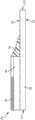
图1A是根据一个实施方式的人工心脏瓣膜的流出侧等距视图;1A is an isometric view of an outflow side of a prosthetic heart valve according to one embodiment;
图1B是图1A所示瓣膜的实施方式的流入侧等距视图;Figure IB is an inflow side isometric view of the embodiment of the valve shown in Figure 1A;
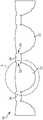
图2是根据一些实施方式的瓣叶构造的前视图;2 is a front view of a leaflet configuration according to some embodiments;
图3是根据一些实施方式的已经展开成平坦取向的图2所示的瓣叶框架的图示;3 is an illustration of the leaflet frame shown in FIG. 2 that has been deployed into a flat orientation, according to some embodiments;
图4是图3中圆圈4的放大图;Fig. 4 is an enlarged view of circle 4 in Fig. 3;
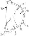
图5显示根据一些实施方式的瓣叶的图示;Figure 5 shows an illustration of a leaflet according to some embodiments;
图6是根据一些实施方式的图4中所示的瓣叶沿线6-6截取的截面图;6 is a cross-sectional view of the leaflet shown in FIG. 4 taken along line 6-6, according to some embodiments;
图7A是根据一些实施方式的瓣叶的截面图;7A is a cross-sectional view of a leaflet according to some embodiments;
图7B是根据一些实施方式的瓣叶的截面图;7B is a cross-sectional view of a leaflet, according to some embodiments;
图7C是根据一些实施方式的瓣叶的截面图;Figure 7C is a cross-sectional view of a leaflet according to some embodiments;
图8A是根据一些实施方式的瓣叶的俯视图;8A is a top view of a leaflet according to some embodiments;
图8B是根据一些实施方式的瓣叶的俯视图;Figure 8B is a top view of a leaflet according to some embodiments;
图8C是根据一些实施方式的图8A中所示瓣叶沿线8C-8C截取的截面图;8C is a cross-sectional view of the leaflet shown in FIG. 8A taken along
图9是根据一些实施方式的瓣叶的俯视图;Figure 9 is a top view of a leaflet according to some embodiments;
图10是根据一些实施方式的瓣叶的俯视图;Figure 10 is a top view of a leaflet according to some embodiments;
图11是根据一些实施方式的瓣叶的俯视图;Figure 11 is a top view of a leaflet according to some embodiments;
图12是根据一些实施方式的瓣叶的俯视图;Figure 12 is a top view of a leaflet according to some embodiments;
图13是根据一些实施方式的瓣叶的俯视图;Figure 13 is a top view of a leaflet according to some embodiments;
图14是根据一些实施方式的瓣叶的俯视图;Figure 14 is a top view of a leaflet according to some embodiments;
图15是根据一些实施方式的图14中所示瓣叶沿线15-15截取的截面图;15 is a cross-sectional view of the leaflet shown in FIG. 14 taken along line 15-15, according to some embodiments;
图16是根据一些实施方式的瓣叶的截面图;Figure 16 is a cross-sectional view of a leaflet according to some embodiments;
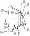
图17是根据一些实施方式的瓣叶的俯视图;Figure 17 is a top view of a leaflet according to some embodiments;
图18是根据一些实施方式的图17中所示瓣叶沿线18-18截取的截面图;Figure 18 is a cross-sectional view of the leaflet shown in Figure 17 taken along line 18-18, according to some embodiments;
图19是根据一些实施方式的瓣叶的俯视图;Figure 19 is a top view of a leaflet according to some embodiments;
图20是根据一些实施方式图19中所示瓣叶沿线20-20截取的截面图;Figure 20 is a cross-sectional view of the leaflet shown in Figure 19 taken along line 20-20, according to some embodiments;
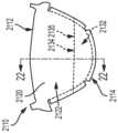
图21是根据一些实施方式的瓣叶的俯视图;Figure 21 is a top view of a leaflet according to some embodiments;
图22是根据一些实施方式图21中所示瓣叶沿线22-22截取的截面图;Figure 22 is a cross-sectional view of the leaflet shown in Figure 21 taken along line 22-22, according to some embodiments;
图23是根据一些实施方式的瓣叶的截面图;Figure 23 is a cross-sectional view of a leaflet according to some embodiments;
图24是根据一些实施方式的瓣叶的截面图;Figure 24 is a cross-sectional view of a leaflet according to some embodiments;
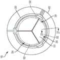
图25是根据一些实施方式的人工瓣膜的流出侧的俯视图;Figure 25 is a top view of the outflow side of a prosthetic valve according to some embodiments;
图26是根据一些实施方式的人工瓣膜的流出侧的俯视图;Figure 26 is a top view of the outflow side of a prosthetic valve according to some embodiments;
图27是根据一些实施方式图25中所示人工瓣膜沿线27-27截取的截面图;Figure 27 is a cross-sectional view of the prosthetic valve shown in Figure 25 taken along line 27-27, according to some embodiments;
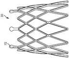
图28A是根据一些实施方式的另一人工瓣膜的流出侧的俯视图;并且Figure 28A is a top view of the outflow side of another prosthetic valve in accordance with some embodiments; and
图28B是图28A所示人工瓣膜的框架的侧视图;Figure 28B is a side view of the frame of the prosthetic valve shown in Figure 28A;
图29和30显示了根据一些实施方式的将人工瓣膜递送至治疗位置的方法。29 and 30 illustrate a method of delivering a prosthetic valve to a treatment site according to some embodiments.
详述detail
本领域的技术人员应理解,可通过构造以实施所需作用的任何数量的方法和设备来实现本公开内容的各个方面。换言之,本文可纳入其它方法和设备以发挥预期的功能。还应注意,本文参考的附图不一定是按比例绘制,而是有可能放大以说明本公开的各个方面,就此而言,附图不应视为限制性的。Those skilled in the art will understand that various aspects of the present disclosure can be implemented by any number of methods and apparatus configured to perform the desired functions. In other words, other methods and apparatus may be incorporated herein to function as intended. It should also be noted that the drawings referred to herein are not necessarily to scale, but may be exaggerated to illustrate various aspects of the present disclosure, and in this regard should not be considered limiting.
尽管可以结合各种原理和信念来描述本文中的实施方式,但是所述的实施方式不应受理论约束。例如,本文中结合人工瓣膜,更具体地,结合心脏人工瓣膜来描述实施方式。但是,本公开范围内的实施方式可以应用于具有相似结构和/或功能的任何瓣膜或机理。另外,本公开范围内的实施方式可以应用于非心脏应用。Although the embodiments herein may be described in conjunction with various principles and beliefs, the described embodiments should not be bound by theory. For example, embodiments are described herein in connection with prosthetic valves, and more particularly in connection with cardiac prosthetic valves. However, embodiments within the scope of the present disclosure may be applied to any valve or mechanism of similar structure and/or function. Additionally, embodiments within the scope of the present disclosure may be applied to non-cardiac applications.
本文在人工瓣膜的背景下所用的术语瓣叶是单向瓣膜的柔性组件,其中所述瓣叶可在压力差影响下工作,在打开和闭合位置之间运动。在打开位置,瓣叶允许血液流动通过瓣膜。在闭合位置,响应于流体压力差而使瓣膜孔阻塞或闭塞,并部分或完全阻止流动。应理解,在一些情况下,相邻瓣叶的接合可进行操作以完全阻止流体(例如血液)流动通过人工瓣膜,而在其他情况下,相邻瓣叶的接合可进行操作以阻挡少于全部(即不是全部)的流体(例如血液)流动通过人工瓣膜。The term leaflet, as used herein in the context of a prosthetic valve, is the flexible component of a one-way valve, wherein the leaflet is operable to move between open and closed positions under the influence of a pressure differential. In the open position, the leaflets allow blood to flow through the valve. In the closed position, the valve orifice is blocked or occluded in response to the fluid pressure differential and flow is partially or completely prevented. It will be appreciated that in some cases the coaptation of adjacent leaflets may operate to completely block fluid (eg, blood) flow through the prosthetic valve, while in other cases the coaptation of adjacent leaflets may operate to block less than all of (ie, not all) fluid (eg, blood) flows through the prosthetic valve.
在包含多个瓣叶的实施方式中,各瓣叶通常与至少一个相邻或邻近放置的瓣叶协作以阻挡或限制血液的逆行流动。血液压差由例如心脏的心室或心房收缩引起,这种压差通常由瓣膜闭合时其一侧上累积的流体压力所产生。当瓣膜流入侧的压力上升到高于瓣膜流出侧的压力时,瓣叶张开,血液从其中流过。当血液经瓣膜流入相邻腔室或血管时,流入侧的压力等于流出侧的压力。当瓣膜流出侧的压力上升到高于瓣膜流入侧的血压时,瓣叶回到闭合位置,通常阻止血液经瓣膜回流。In embodiments comprising multiple leaflets, each leaflet generally cooperates with at least one adjacent or adjacently placed leaflet to block or restrict retrograde flow of blood. The blood pressure differential is caused, for example, by the contraction of the ventricles or atria of the heart, and is usually created by the fluid pressure that builds up on one side of the valve as it closes. When the pressure on the inflow side of the valve rises above the pressure on the outflow side of the valve, the valve leaflets open and blood flows through them. When blood flows through a valve into an adjacent chamber or vessel, the pressure on the inflow side equals the pressure on the outflow side. When the pressure on the outflow side of the valve rises above the blood pressure on the inflow side of the valve, the valve leaflets return to the closed position, normally preventing backflow of blood through the valve.
本文所述的实施方式和实例包括用于人工瓣膜的各种设备、系统和方法,例如但不限于心脏瓣膜置换。在一些实例中,人工瓣膜以单向瓣膜的方式工作,其中,人工瓣膜限定了瓣膜孔,瓣叶张开时允许血液流入瓣膜孔,而闭合时阻断瓣膜孔,防止血液响应于差压而流动。在本公开中,主要结合人工瓣膜或具有类似结构和/或功能的机理(包括手术植入的瓣膜)来描述实例,但是应容易理解,这些实例的特征同样适用于经导管心脏瓣膜应用。Embodiments and examples described herein include various devices, systems, and methods for prosthetic valves, such as, but not limited to, heart valve replacement. In some examples, the prosthetic valve operates as a one-way valve, wherein the prosthetic valve defines a valve aperture that allows blood to flow into the valve aperture when the leaflets are open and blocks the valve aperture when closed, preventing blood flow in response to differential pressure. In this disclosure, examples are primarily described in conjunction with prosthetic valves or mechanisms having similar structure and/or function, including surgically implanted valves, but it should be readily understood that features of these examples are equally applicable to transcatheter heart valve applications.
图1A和1B分别是一实施方式中人工心脏瓣膜形式的人工瓣膜100的流出和流入的视图。图1A和1B所示的人工瓣膜100的组件包括:瓣叶框架200和连接至瓣叶框架200的多个瓣叶310。在一些实例中,人工瓣膜100包括缝合罗口(sewing cuff)400。1A and 1B are views, respectively, of outflow and inflow of a
瓣叶框架200可操作以保持并支撑瓣叶310。合适的瓣叶框架构造和缝合罗口的实例显示并见述于美国专利申请号13/833,650、14/973,589和14/853,654中,各申请的内容通过引用纳入本文。应理解的是,可以将瓣叶框架200蚀刻、切割、激光切割、压印或三维打印(或者是其他的合适工艺加工)成环形结构或材料片材,并且然后使该片材形成为环形结构。在多个实例中,瓣叶框架200可包括例如但不限于:任何生物相容且可弹性变形的金属或聚合物材料,包括形状记忆材料,例如镍钛诺(一种镍钛合金)。适用于瓣叶框架200的其它材料包括但不限于:其它钛合金、不锈钢、钴镍合金、聚丙烯、聚对苯二甲酸乙二酯、PEEK、乙酰均聚物、乙酰共聚物,其它合金、聚合物和热塑性塑料、或通常是生物相容并具有足够的物理和机械性能以用作本文所述瓣叶框架200的任意其它材料。The
在各种实施方式中,瓣叶框架200的一个或多个部分可以覆盖有适于促进组织向内生长的材料。例如,瓣叶框架200可以用适用于促进组织向内生长的材料进行包裹。在各种实例中,可以将该组织向内生长促进材料施加至整个瓣叶框架200,或者施加到小于全部的瓣叶框架200。例如,用于促进组织向内生长的合适材料可以连接至瓣叶框架的瓣叶框架内表面和瓣叶框架外表面,并且任选地在瓣叶附着前连接至瓣叶框架突起部之间。可以应用于瓣叶框架200(或人工瓣膜100的其他部分)的材料的一些非限制性实例包括膨胀型聚四氟乙烯(ePTFE),例如ePTFE膜,织物,薄膜或涂层,以及聚对苯二甲酸乙二醇酯织物(例如涤纶织物)。In various embodiments, one or more portions of the
将瓣叶310连接至瓣叶框架200,使得其各自基本从瓣叶框架200向三相点348径向向内延伸,如图1A所示。图2至3显示了根据一些实施方式的瓣叶310。图2是包括多个瓣叶310的瓣叶构造300的前视图。图3是图2中所示的瓣叶构造300的示意图,其已经纵向切开、打开并且平放以更好地显示瓣叶310的特征。应理解,通过图3中的瓣叶形成的切割位置和图示仅用于说明目的,并且不应解释为限制。还应理解,尽管本文讨论的实施方式和实例包括人工瓣膜,所述人工瓣膜具有多个瓣叶,以及由多个瓣叶组成的瓣叶构造,但是本文所讨论的组织向内生长幕和吸收技术可应用于用于包括一个、两个、三个或超过三个瓣叶的人工瓣膜的合成瓣叶。The
图3至图5显示了多个非限制性的实例性瓣叶构造。图4是图3的圆圈的放大俯视图,并且显示了图3的瓣叶构造300的瓣叶310之一。图5是用于人工瓣膜构造的替代性瓣叶510的俯视图,其中,人工瓣膜的各瓣叶510形成了独立的整体组件,该独立的整体组件连接至人工瓣膜的瓣叶框架,所述瓣叶框架独立于人工瓣膜的任何其他瓣叶。如图所示,在平面构造中,瓣叶310和510通常都构造成具有弓形侧面的等腰梯形形状。然而,应理解的是,当将瓣叶施加到人工瓣膜的瓣叶框架上时,所述瓣叶采用不同的形状(例如,参见图1A和1B)。例如,当连接至瓣叶框架时,瓣叶所采用的形状至少部分由瓣叶框架的形状、瓣叶附着于瓣叶框架的部分的形状以及操作过程中瓣叶遇到的流体压力等因素来确定。在一些实例中,瓣叶的形状可能会受其它技术(例如但不限于,瓣叶模塑和定型)的影响或被其改变。3-5 show a number of non-limiting example leaflet configurations. FIG. 4 is an enlarged top view of the circle of FIG. 3 and shows one of the
现在具体参考图4,各瓣叶310通常包括瓣叶附着区域330、瓣叶腹部区域322和瓣叶自由边缘312。在一些实例中,瓣叶腹部区域322终止于瓣叶自由边缘312。在一些实例中,作为附加或替代方式,瓣叶腹部区域322终止于瓣叶附着区域330。在一些实例中,瓣叶基底325限定于瓣叶附着区域330和瓣叶腹部区域322之间的交叉部处。在各种实例中,当组装到人工瓣膜100中时,瓣叶310的瓣叶腹部区域322是瓣叶310的操作部分。在各种实例中,瓣叶附着区域330对应于构造成附着至瓣叶框架200的瓣叶310部分。在一些实例中,瓣叶附着区域330围绕瓣叶310的一部分外周延伸,并且终止于瓣叶自由边缘的中心点的相对侧上的瓣叶自由边缘312。在一些实例中,瓣叶附着区域330与瓣叶腹部区域322毗连。在一些实例中,瓣叶310可以构造成围绕瓣叶框架200的一个或多个部分周围包裹。用于使瓣叶310附着至瓣叶框架200的合适方法的一些实例显示并见述于如上所述的美国专利申请号13/833,650、14/973,589和14/853,654。Referring now specifically to FIG. 4 , each
图5所示的瓣叶510类似地包括:瓣叶附着区域530、瓣叶腹部区域522、瓣叶自由边缘512和限定在瓣叶附着区域530与瓣叶腹部区域522之间的交叉部处的瓣叶基底525。如图5所示,瓣叶510包括:延伸到瓣叶腹部区域522中的组织向内生长幕532,以使边界534限定于组织向内生长幕532与瓣叶腹部区域522的交叉部处。另外,如图所示,瓣叶510包括用于将瓣叶510固定到相应的瓣叶框架的一个或多个特征。尽管在图5中显示为瓣叶孔508,但是应理解,用于将瓣叶510固定至相应的瓣叶框架的这些特征可以采用合适的任意替代形式,而不背离本公开的精神或范围。还应理解,虽然未以此显示,但是瓣叶510可以包括用于将瓣叶510固定至相应瓣叶框架200的类似特征(例如,瓣叶孔)。The
根据各种实施方式,本文讨论的包括瓣叶的各种瓣叶构造是合成的,因为瓣叶以及瓣叶构造的各种其他部分包含一种或多种生物相容材料,所述生物相容材料不是生物来源的并且具有足够的顺应性和强度以用于特定目的,例如生物相容聚合物。在一些实施方式中,瓣叶包括膜,所述膜与弹性材料例如含氟弹性体组合以形成复合材料,如本文所公开。应理解是,尽管讨论了关于瓣叶构造300和900的各种实例,但是本文所讨论的各种实例和实施方式可以普遍地应用于本文所讨论瓣叶构造中的各瓣叶构造和/或瓣叶构造的各种组件。According to various embodiments, the various leaflet constructions discussed herein, including the leaflets, are synthetic in that the leaflets, as well as various other portions of the leaflet construction, comprise one or more biocompatible materials that are biocompatible Materials are not biologically derived and have sufficient compliance and strength for specific purposes, such as biocompatible polymers. In some embodiments, the leaflets include a membrane that is combined with an elastic material, such as a fluoroelastomer, to form a composite material, as disclosed herein. It should be understood that although various examples are discussed with respect to the
在一些实例中,包括瓣叶310的瓣叶构造300可以通过以下方式制造:从已切成如图2和3所示的形状的聚合物材料的圆柱体开始。在一些其他实例中,多个瓣叶310由聚合物材料片材制成,该片材已切成如图4所示的形状,并且随后连接在一起成为如图2和3所示的环形形状。在一些其他实例中,瓣叶构造300和/或瓣叶310可通过一个或多个压缩或注射成型工艺来形成。In some examples, the
如上所述,瓣叶310通常形成为合成复合材料。在各种实施方式中,瓣叶310包括与组织向内生长幕组合的下方合成瓣叶基底材料,所述组织向内生长幕可以纳入瓣叶基底材料中和/或与瓣叶基底材料连接,如下文进一步解释。在一些实例中,形成下方合成瓣叶基底的复合材料包括:膨胀型含氟聚合物膜,其包括在原纤维基质内的多个空间、以及吸收或以其他方式纳入膨胀型含氟聚合物膜中的弹性材料,例如含氟弹性体。在一些实例中,下方瓣叶基底包括经吸收的多孔单层。应当理解,可以组合多种类型的含氟聚合物膜和多种类型的弹性材料(和非弹性材料)以形成下方瓣叶基底的复合材料,同时仍在本公开的精神和范围内。还应理解,在本发明的精神和范围内,所述弹性材料可包括多种弹性体、多种类型的非弹性组分如无机填料、治疗剂、辐射不透明标记物等。As mentioned above, the
进一步的实例包括包含至少一个含氟聚合物膜层的瓣叶构造300,其中,所述瓣叶构造300包含具有超过一层含氟聚合物膜层的复合物,并且至少一层含氟聚合物膜层是膨胀型含氟聚合物膜层。在一些实例中,瓣叶构造300包括:具有包含多个孔的至少一层含氟聚合物膜层的复合材料和存在于至少一层含氟聚合物膜层的孔中的弹性体和/或弹性材料。Further examples include a
在各种实例中,本文所述的任意瓣叶构造(例如,瓣叶构造)可以由生物相容合成材料(例如,包括ePTFE和ePTFE复合材料,或根据需要的其它材料)形成。可能适用于合成瓣叶的其它生物相容聚合物包括但不限于以下组:氨基甲酸酯、硅酮(有机聚硅氧烷)、硅氧烷-氨基甲酸酯共聚物、苯乙烯/异丁烯共聚物、聚异丁烯、乙烯-乙酸乙烯酯共聚物、聚酯共聚物、尼龙共聚物、氟化烃聚合物,和前述聚合物的共聚物或混合物。In various examples, any of the leaflet constructs described herein (eg, leaflet constructs) can be formed from biocompatible synthetic materials (eg, including ePTFE and ePTFE composites, or other materials as desired). Other biocompatible polymers that may be suitable for use in synthetic valve leaflets include, but are not limited to, the following groups: urethanes, silicones (organopolysiloxanes), siloxane-urethane copolymers, styrene/isobutylene Copolymers, polyisobutylene, ethylene-vinyl acetate copolymers, polyester copolymers, nylon copolymers, fluorinated hydrocarbon polymers, and copolymers or mixtures of the foregoing polymers.
如本文中所用的术语“弹性体”是指一种聚合物或聚合物混合物,其具有能拉伸至其原始长度的至少1.3倍,并在释放时迅速缩回至近似等于其原始长度的能力。术语“弹性材料”是指表现出类似于弹性体的拉伸和回复性质的聚合物或聚合物混合物,但是不一定达到相同程度的拉伸和/或回复。术语“非弹性材料”是指表现出拉伸和回复性质与弹性体或弹性材料不同的聚合物或聚合物混合物,即,被认为不是弹性体或弹性材料。The term "elastomer" as used herein refers to a polymer or polymer blend that has the ability to stretch to at least 1.3 times its original length, and to retract rapidly to approximately its original length upon release . The term "elastic material" refers to a polymer or polymer blend that exhibits stretch and recovery properties similar to elastomers, but not necessarily to the same degree of stretch and/or recovery. The term "non-elastic material" refers to a polymer or polymer mixture that exhibits stretch and recovery properties different from elastomeric or elastic materials, ie, is not considered an elastomeric or elastic material.
根据本文的一些实施方式,瓣叶构造包括复合材料,该复合材料具有含有多个孔和/或空间的至少一层多孔合成聚合物膜层以及填充至少一层合成聚合物膜层的孔和/或空间的弹性体和/或弹性材料和/或非弹性材料。根据其他实例,瓣叶构造还包括在复合材料上的弹性体和/或弹性材料和/或非弹性材料层。根据一些实例,所述复合材料包含约10-90重量%的多孔合成聚合物膜。According to some embodiments herein, a leaflet construct includes a composite material having at least one layer of porous synthetic polymer film containing a plurality of pores and/or spaces and pores filled with the at least one layer of synthetic polymer film and/or or dimensional elastomers and/or elastic and/or inelastic materials. According to other examples, the leaflet construction further includes a layer of elastomeric and/or elastic and/or inelastic material on the composite material. According to some examples, the composite material comprises about 10-90% by weight of the porous synthetic polymer membrane.
多孔合成聚合物膜的实例包括膨胀型含氟聚合物膜,其具有限定孔和/或空间的节点和原纤维结构。在一些实例中,膨胀型含氟聚合物膜是膨胀型聚四氟乙烯(ePTFE)膜。多孔合成聚合物膜的另一实例包括微孔聚乙烯膜。Examples of porous synthetic polymer membranes include expanded fluoropolymer membranes having nodal and fibrillar structures that define pores and/or spaces. In some examples, the expanded fluoropolymer membrane is an expanded polytetrafluoroethylene (ePTFE) membrane. Another example of a porous synthetic polymer membrane includes a microporous polyethylene membrane.
弹性体和/或弹性材料和/或非弹体材料的实例包括但不限于:四氟乙烯和全氟甲基乙烯基醚的共聚物(TFE/PMVE共聚物)、(全)氟烷基乙烯基醚(PAVE)、氨基甲酸酯、硅酮(有机聚硅氧烷)、硅-氨基甲酸酯的共聚物、苯乙烯/异丁烯共聚物、聚异丁烯、乙烯-乙酸乙烯酯共聚物、聚酯共聚物、尼龙共聚物、氟化烃聚合物,或上述中每一种的混合物和共聚物。在一些实例中,TFE/PMVE共聚物是弹性体,其基本包含60至20重量%的四氟乙烯和40至80重量%的全氟甲基乙烯基醚。在一些实例中,TFE/PMVE共聚物是弹性材料,其基本包含67至61重量%的四氟乙烯和33至39重量%的全氟甲基乙烯基醚。在一些实例中,TFE/PMVE共聚物是非弹性材料,其基本包含73至68重量%的四氟乙烯和27至32重量%的全氟甲基乙烯基醚。TFE-PMVE共聚物的TFE和PMVE组分以重量%表示。作为参考,40、33-39和27-32重量%的PMVE分别对应于29、23-28和18-22摩尔%。Examples of elastomeric and/or elastomeric and/or non-elastomeric materials include, but are not limited to: copolymers of tetrafluoroethylene and perfluoromethyl vinyl ether (TFE/PMVE copolymers), (per)fluoroalkyl ethylene base ether (PAVE), urethane, silicone (organopolysiloxane), silicone-urethane copolymer, styrene/isobutylene copolymer, polyisobutylene, ethylene-vinyl acetate copolymer, poly Ester copolymers, nylon copolymers, fluorinated hydrocarbon polymers, or mixtures and copolymers of each of the foregoing. In some examples, the TFE/PMVE copolymer is an elastomer consisting essentially of 60 to 20 wt% tetrafluoroethylene and 40 to 80 wt% perfluoromethyl vinyl ether. In some examples, the TFE/PMVE copolymer is an elastomeric material consisting essentially of 67 to 61 wt% tetrafluoroethylene and 33 to 39 wt% perfluoromethyl vinyl ether. In some examples, the TFE/PMVE copolymer is a non-elastomeric material consisting essentially of 73 to 68 wt % tetrafluoroethylene and 27 to 32 wt % perfluoromethyl vinyl ether. The TFE and PMVE components of the TFE-PMVE copolymer are expressed in % by weight. For reference, PMVEs of 40, 33-39 and 27-32 wt % correspond to 29, 23-28 and 18-22 mol %, respectively.
在一些实例中,TFE-PMVE共聚物表现出弹性体、弹性性质和/或非弹性性质。In some examples, the TFE-PMVE copolymer exhibits elastomeric, elastic and/or inelastic properties.
在一些实例中,复合材料还包括TFE-PMVE共聚物层或涂层,其分别包含约73至约68重量%的四氟乙烯和约27至约32重量%的全氟甲基乙烯基醚。In some examples, the composite material further includes a TFE-PMVE copolymer layer or coating comprising about 73 to about 68 wt % tetrafluoroethylene and about 27 to about 32 wt % perfluoromethyl vinyl ether, respectively.
在一些实例中,瓣叶构造是吸收有TFE-PMVE共聚物的膨胀型聚四氟乙烯(ePTFE)膜,该TFE-PMVE共聚物分别包含约60至约20重量%的四氟乙烯和约40至约80重量%的全氟甲基乙烯基醚,瓣叶构造300还包括TFE-PMVE共聚物涂层,在血液接触表面上具有TFE-PMVE共聚物涂层,其分别包含约73至约68重量%的四氟乙烯和约27至约32重量%的全氟甲基乙烯基醚。In some examples, the leaflet construct is an expanded polytetrafluoroethylene (ePTFE) membrane imbibed with a TFE-PMVE copolymer comprising about 60 to about 20 weight percent tetrafluoroethylene and about 40 to about 40 to About 80% by weight perfluoromethyl vinyl ether,
如上所述,弹性体和/或弹性材料和/或非弹性材料可以与膨胀型含氟聚合物膜组合,使弹性体和/或弹性材料和/或非弹体材料基本占据膨胀型含氟聚合物膜内的所有的空隙或孔。As mentioned above, the elastomeric and/or elastomeric and/or non-elastomeric material may be combined with the expanded fluoropolymer film such that the elastomeric and/or elastomeric and/or non-elastomeric material substantially occupies the expanded fluoropolymer All voids or pores in the film.
根据一实施方式,复合材料包括由多孔ePTFE膜制成的膨胀型含氟聚合物材料,例如通常见述于Bacino的美国专利第7306729号。According to one embodiment, the composite material comprises an expanded fluoropolymer material made of porous ePTFE membrane, such as generally described in US Patent No. 7,306,729 to Bacino.
用于形成一些所述复合物的膨胀型含氟聚合物膜可包含PTFE均聚物。在替代性实施方式中,可使用PTFE的掺混物、可膨胀改性PTFE和/或PTFE的膨胀型共聚物。合适的含氟聚合物材料的非限制性实例见述于:例如,Branca的美国专利第5,708,044号;Baillie的美国专利第6,541,589号;Sabol等人的美国专利第7,531,611号;Ford的美国专利申请第11/906,877号;以及Xu等人的美国专利申请第12/410,050号。The expanded fluoropolymer membranes used to form some of the composites may comprise PTFE homopolymers. In alternative embodiments, blends of PTFE, expandable modified PTFE, and/or expanded copolymers of PTFE may be used. Non-limiting examples of suitable fluoropolymer materials are described in: eg, US Patent No. 5,708,044 to Branca; US Patent No. 6,541,589 to Baillie; US Patent No. 7,531,611 to Sabol et al.; US Patent Application No. 7,531,611 to Ford 11/906,877; and US Patent Application Serial No. 12/410,050 to Xu et al.
在各种实施方式中,瓣叶310以促进组织向内生长的方式构造。在一些实施方式中,瓣叶310可以构造成促使组织向内生长和增殖跨越形成瓣叶310的一种或多种材料的一个或多个离散的区域、部分或区段上,或者跨越形成瓣叶310的一种或多种材料的整体。可以在瓣叶310的流出侧或表面上,和/或在瓣叶310的流入侧或表面上,和/或在形成瓣叶的一种或多种材料内促进组织向内生长和增殖。In various embodiments, the
根据一些实例,如下文将更详细讨论的,通过将一种或多种合成的组织向内生长幕连接至一种或多种下方瓣叶基底材料上以促进组织生长(或并未以其它方式防止或抑制生长)到一个或多个组织向内生长幕中和/或之上,从而帮助促使组织向内生长。即,在一些实例中,可以将构造成促进组织向内生长的一层或多层施加到下方瓣叶结构或材料上。在一些实例中,如本文所述,下方瓣叶结构或材料可以构造成抑制或防止组织向内生长。According to some examples, as will be discussed in more detail below, tissue growth is promoted (or not otherwise) by attaching one or more synthetic tissue ingrowth tents to one or more underlying leaflet base materials. prevent or inhibit growth) into and/or over one or more tentoriums of tissue ingrowth, thereby helping to promote tissue ingrowth. That is, in some examples, one or more layers configured to promote tissue ingrowth may be applied to the underlying leaflet structure or material. In some examples, the inferior leaflet structure or material can be configured to inhibit or prevent tissue ingrowth, as described herein.
作为附加或替代方式,在一些实例中,通过使形成瓣叶310的一种或多种材料的一个或多个部分选择地吸收有例如一种或多种含氟弹性体来帮助组织向内生长。也就是说,在一些实例中,除了将一个或多个合成的组织向内生长幕连接至一种或多种下方瓣叶基底材料上之外或作为其替代,下方瓣叶基底材料本身构造成促进或适应组织向内生长。在一些这样的实例中,如下文更详细地讨论的,使下方瓣叶基底材料构造成促使组织生长(或以其他方式未防止或抑制生长)到一种或多种下方瓣叶基底材料的一个或多个离散或指定的区段、部分和/或区域中和/或上。Additionally or alternatively, in some examples, tissue ingrowth is aided by selectively absorbing one or more portions of the one or more materials forming the
在各种实施方式中,组织向内生长幕通常包括膨胀型含氟聚合物膜,其包括在原纤维基质内的多个空间,并且适合于促进和支持组织向内生长。其他非限制的实例性材料包括其它生物相容多孔材料,例如编织PTFE。然而,如上所述以及如下文更详细讨论的,在一些实例中,组织向内生长幕可以以一个或多个涂层的形式施加到下方瓣叶基底上。In various embodiments, the tissue ingrowth tent generally includes an expanded fluoropolymer membrane that includes a plurality of spaces within a fibrillar matrix and is adapted to promote and support tissue ingrowth. Other non-limiting example materials include other biocompatible porous materials such as woven PTFE. However, as discussed above and in more detail below, in some examples, the tissue ingrowth tent may be applied to the underlying leaflet base in one or more coatings.
在一些实例中,组织向内生长幕包括由多孔ePTFE膜制成的膨胀型含氟聚合物材料。然而,应理解组织向内生长幕可由多种不同类型的膜形成,包括其它含氟聚合物膜和其它生物相容多孔材料,例如编织PTFE。例如,可膨胀含氟聚合物可以包括PTFE均聚物。在一些实例中,组织向内生长幕可以由六氟丙烯和四氟乙烯的共聚物形成,例如氟化乙烯丙烯(FEP)。在一些实例中,可使用PTFE的掺混物、可膨胀改性PTFE和/或PTFE的膨胀型共聚物。因此,应理解,组织向内生长幕可以由多种不同的聚合物材料形成,前提是其是生物相容的并且具有或被改性成包括适合于促进或支持组织向内生长的合适微结构。在各种实例中,取决于选择的材料,组织向内生长幕的厚度范围可以为一微米至四百微米。In some examples, the tissue ingrowth curtain includes an expanded fluoropolymer material made of porous ePTFE membrane. However, it should be understood that the tissue ingrowth tent can be formed from many different types of membranes, including other fluoropolymer membranes and other biocompatible porous materials, such as woven PTFE. For example, the expandable fluoropolymer can include a PTFE homopolymer. In some examples, the tissue ingrowth tent can be formed from a copolymer of hexafluoropropylene and tetrafluoroethylene, such as fluorinated ethylene propylene (FEP). In some examples, blends of PTFE, expandable modified PTFE, and/or expanded copolymers of PTFE may be used. Thus, it should be understood that the tissue ingrowth tent can be formed from a variety of different polymeric materials, provided that it is biocompatible and has or is modified to include a suitable microstructure suitable for promoting or supporting tissue ingrowth . In various examples, depending on the material selected, the thickness of the tissue ingrowth curtain can range from one micron to four hundred microns.
在一些实例中,聚合物材料可包括用于支撑组织向内生长的一个或多个天然存在的和/或一个或多个人工产生的孔、浮雕(reliefs)或通道。可能适用于形成组织向内生长幕的其它生物相容多孔材料包括但不限于以下组:氨基甲酸酯、含氟聚合物、苯乙烯/异丁烯共聚物、聚异丁烯、乙烯-乙酸乙烯酯共聚物、聚酯共聚物、尼龙共聚物、氟化烃聚合物和前述聚合物的共聚物或混合物。In some examples, the polymeric material may include one or more naturally occurring and/or one or more artificially created pores, reliefs or channels for supporting tissue ingrowth. Other biocompatible porous materials that may be suitable for use in forming a tentacle of tissue ingrowth include, but are not limited to, the following groups: urethanes, fluoropolymers, styrene/isobutylene copolymers, polyisobutylene, ethylene-vinyl acetate copolymers , polyester copolymers, nylon copolymers, fluorinated hydrocarbon polymers and copolymers or mixtures of the foregoing polymers.
现在转向图6和图7A至7C,在各种实例中,将一个或多个合成组织向内生长幕332施加到瓣叶基底320。图6是瓣叶310的截面图。图7A至7C是瓣叶710的截面图(类似于图6的截面图)。例如,图7B是图9中所示的瓣叶710沿线7B-7B截取的截面图。图7A和7C是类似于图7C的截面图,不同的是,图7A和7C所示的瓣叶710包括用于将组织向内生长幕732施加到下方瓣叶基底720上的替代构造。Turning now to FIGS. 6 and 7A-7C , in various examples, one or more synthetic
如图4和6所示,瓣叶310包括瓣叶基底320和组织向内生长幕332。如上所述,在各种实例中,将组织向内生长幕332施加到小于全部的瓣叶基底320的一部分。例如,如图4和图6所示,组织向内生长幕332从与瓣叶自由边缘312相反的瓣叶310的边缘314延伸,并延伸到瓣叶腹部区域322上,向着瓣叶自由边缘312延伸。在各种实例中,组织向内生长幕332延伸到一部分瓣叶腹部区域322上或跨越一部分瓣叶腹部区域322并终止于其上,使得边界334限定于组织向内生长幕332和瓣叶腹部区域322之间的交叉部处。如图4所示,边界334通常与边缘314互补,但是,如下所述,可以构想其他构造。如下面关于图8至图13进一步讨论的,瓣叶310可构造成具有终止于瓣叶腹部区域322中的组织向内生长幕,使得边界334实际上采用了几乎线性或非线性、连续或不连续(例如,多个边界)轮廓。As shown in FIGS. 4 and 6 ,
而且,如上所述,如图6所示,瓣叶310包括多个组织向内生长幕,例如组织向内生长幕332a和组织向内生长幕332b。即,瓣叶310构造成具有设置在瓣叶310的流入侧316和流出侧318两者上的组织向内生长幕。因此,应理解,瓣叶310可以构造成具有组织向内生长幕332,该组织向内生长幕332连接至或以其他方式设置在瓣叶基底320的一侧或两侧的一个或多个部分上。如图所示,使第一组织向内生长幕332a连接至或以其他方式设置在瓣叶基底320的流入侧316上,使第二组织向内生长幕332b连接至或以其他方式设置在瓣叶基底320的流出侧318上。Also, as described above, as shown in FIG. 6, the
虽然瓣叶310在图6中显示为包括分别设置在第一侧(例如,流入侧316)和第二侧(例如,流出侧318)上方的第一组织向内生长幕和第二组织向内生长幕332a和332b,但是应理解,在各种其他实例中,瓣叶310可以构造为使组织向内生长幕布仅设置在瓣叶基底320的第一侧316和第二侧318之一上。例如,如图7A中所示,瓣叶710包括下方瓣叶基底720和设置在瓣叶710的第一侧716上(例如,在下方瓣叶基底720的流入侧上)的第一组织向内生长幕732。应理解,第一组织向内生长幕732或者可以设置在瓣叶710的第二侧718上(例如,在下方瓣叶基底720的流出侧上)。Although
另外,如上所述,在一些实施例中,瓣叶310构造为使一个或多个组织向内生长幕732完全覆盖下方瓣叶基底720的一侧或两侧。例如,如图7B和9中所示,瓣叶710包括下方瓣叶基底720和设置在瓣叶710的第二侧718上的第一组织向内生长幕732,以使得第一组织向内生长幕732完全覆盖瓣叶710的第二侧718。如上所述,应理解,作为替代形式,第一组织向内生长幕732可以设置在瓣叶710的第一侧716上。此外,如上所述,在一些实例中,除了设置在瓣叶710的第一侧716上的任意组织向内生长幕之外,可以将第二组织向内生长幕设置在瓣叶710的第二侧718上。例如,如图7C中所示,瓣叶710包括下方瓣叶基底720和设置在瓣叶710的第一侧716上(例如,在下方瓣叶基底720的流入侧上)的第一组织向内生长幕732,以使得第一组织向内生长幕732完全覆盖瓣叶710的第一侧716。如图7C中所示,第二组织向内生长幕732b设置在瓣叶710的第二侧718上(例如,在下方瓣叶基底720的流出侧上),以使得第二组织向内生长幕732b完全覆盖瓣叶710的第二侧718。Additionally, as described above, in some embodiments, the
另外,虽然图6所示的第一和第二组织向内生长幕332a和332b基本是彼此的镜像,但是瓣叶310可以构造成使得设置在瓣叶基底320的第一侧(例如,流入侧)上的第一组织向内生长幕具有与设置在瓣叶基底320的第二侧(例如,流出侧)上的第二组织向内生长幕不同的轮廓和/或横截面。例如,在一些实例中,考虑到人工瓣膜100的流入侧和流出侧的不同环境条件和动力学,可能希望将瓣叶构造成使得瓣叶的第一侧包括具有第一尺寸和/或第一材料和/或第一形状和/或第一横截面和/或具有第一轮廓的第一边界的第一组织向内生长幕,并且使得瓣叶的第二侧包括具有第二尺寸和/或第二材料和/或第二形状和/或第二横截面和/或具有第二轮廓的第二边界的第二组织向内生长幕。Additionally, although the first and second
例如,如图8A至8C所示,类似于瓣叶310,瓣叶810包括下方瓣叶基底820、瓣叶自由边缘812、边缘814、第一侧和第二侧816和818、瓣叶腹部区域822、瓣叶基底825和瓣叶附着区域830。瓣叶810还包括:设置在瓣叶810的一部分第一侧816上(例如,在下方瓣叶基底820的流入侧上)的第一组织向内生长幕832a、以及设置在第二侧818上的第二组织向内生长幕832b。第一组织向内生长幕832a延伸到第一侧816上的一部分瓣叶腹部区域822上或跨越一部分瓣叶腹部区域822并终止,使得边界834a限定于第一组织向内生长幕832a和瓣叶腹部区域822之间的交叉部处。第二组织向内生长幕832b延伸跨越第二侧818上的瓣叶腹部区域822上并终止,使得边界834b限定于第二组织向内生长幕832b和瓣叶腹部区域822之间的交叉部处(在该情况下,其对应于瓣叶自由边缘812)。因此,如图所示,第二组织向内生长幕832b具有与第一组织向内生长幕832a不同的横截面和/或边界轮廓和/或形状和/或尺寸。For example, as shown in Figures 8A-8C, similar to
图10至图13显示了包括组织向内生长幕332的瓣叶310的各种另外构造。图10显示了具有组织向内生长幕332的瓣叶310,所述组织向内生长幕332被施加至一部分瓣叶基底320上并且终止于瓣叶自由边缘312和边缘314之间的近似中点处的瓣叶腹部区域322中,使边界334是基本线性的。应理解,在一些其它实例中,组织向内生长幕332可以大于或小于图10所示,以使得图10所示的线性边界可以转变为更接近(或远离)瓣叶自由边缘312。FIGS. 10-13 show various additional configurations of
另外,尽管组织向内生长幕可终止于瓣叶腹部,使边界334采用线性轮廓(参见例如图10),但是在一些其他实例中,组织向内生长幕可终止于瓣叶腹部,以使边界334采用非线性轮廓。图11和图12显示了具有组织向内生长幕332的瓣叶310,所述组织向内生长幕332被施加至一部分瓣叶基底320上并且终止于瓣叶腹部区域322,使边界334采用非线性形状。如图11所示,边界334相对于瓣叶自由边缘312采用凸形形状。如图12所示,边界334相对于瓣叶自由边缘312采用凹形形状。在一些实例中,组织向内生长幕可在其终止于瓣叶自由边缘312的地方逐渐变窄。在其它实例中,组织向内生长幕逐渐变窄至边缘314。在一些实例中,这种逐渐变窄用于使在相邻放置的瓣叶之间生长(例如,从一个组织向内生长幕跨越相邻放置的瓣叶桥接)的组织最小化。Additionally, while the tent of tissue ingrowth may terminate at the leaflet abdomen, such that the
如上所述,在一些实例中,可以将一个或多个组织向内生长幕施加到下方瓣叶基底上,使得瓣叶腹部区域和组织向内生长幕之间的边界轮廓是不连续的。现在参考图13,瓣叶310包括施加到瓣叶基底320的第一侧的第一部分的第一组织向内生长幕332a和施加到瓣叶基底320的第一侧的第二部分上的第二组织向内生长幕332b。如图所示,瓣叶310包括第一边界334a和第二边界334b。尽管图13中所示的瓣叶310包括施加至下方瓣叶基底一侧上的两个不同的组织向内生长幕,但是应理解,可以将三个或更多个不同的组织向内幕施加至下方瓣叶基底给定侧上,而不会背离本公开的精神或范围。例如,在一些实例中,可以将多个不同的组织向内生长幕施加到下方瓣叶基底的给定侧上,以实现指定的图案(例如,平铺的(tiled))。As described above, in some examples, one or more tents of tissue ingrowth may be applied to the underlying leaflet base such that the boundary contour between the leaflet ventral region and the tissue ingrowth tent is discontinuous. Referring now to FIG. 13 , the
根据本领域技术人员已知的方法,本文讨论的组织向内生长幕可施加、结合至下方瓣叶基底、或以其他方式与下方瓣叶基底连接。例如,在一些实例中,可以使用一种或多种粘合剂(例如FEP)将组织向内生长幕结合至下方组织瓣叶基底。其他合适的粘合剂包括但不限于:氨基甲酸酯、热塑性塑料、含氟聚合物、硅氧烷/氨基甲酸酯掺混物、环氧树脂、含氟弹性体、FEP、以及FEP的共聚物。可将该粘合剂施加至下方瓣叶基底和组织向内生长幕中的一个或多个上。在一些这样的实例中,在组合下方瓣叶基底和组织向内生长幕之前,将下方粘合剂芯吸或吸收到下方瓣叶基底和/或组织向内生长幕中。在一些实例中,作为附加或者替代方式,下方瓣叶基底和组织向内生长幕可以经受一种或多种热处理和/或压制工艺,以促进组织向内生长幕和下方瓣叶基底之间的结合。The tissue ingrowth tents discussed herein may be applied, bonded to, or otherwise connected to, the underlying leaflet bases according to methods known to those of skill in the art. For example, in some instances, one or more adhesives (eg, FEP) can be used to bond the tissue ingrowth tent to the underlying tissue leaflet base. Other suitable adhesives include, but are not limited to: urethanes, thermoplastics, fluoropolymers, silicone/urethane blends, epoxies, fluoroelastomers, FEP, and FEP's copolymer. The adhesive can be applied to one or more of the underlying leaflet base and the tissue ingrowth tent. In some such instances, the underlying adhesive is wicked or absorbed into the underlying leaflet base and/or the tissue ingrowth tent prior to combining the underlying leaflet base and the tissue ingrowth tent. In some instances, additionally or alternatively, the underlying leaflet base and the tissue ingrowth tent may be subjected to one or more heat treatments and/or pressing processes to promote the formation of a bond between the tissue ingrowth tent and the underlying leaflet base. combine.
尽管上文讨论的组织向内生长幕通常包括与下方瓣叶基底粘结、施加或以其他方式连接的膜、薄膜、编织物或其他结构,但如上所述,在一些实例中,组织向内生长幕可以以一个或多个涂层的形式施加至下方瓣叶基底。在一些这样的实例中,使连贯不规则网络分布或沉积在下方瓣叶基底的一个或多个部分、区域、区段、地区或区上。分布该连贯的干不规则网络的实例显示并见述于美国专利申请号12/879,333中,其内容通过引用纳入本文。在一些实例中,如本领域技术人员理解的,将连贯不规则网络施加至下方瓣叶基底的一个或多个部分,以产生适合于支持组织的向内生长和增殖的表面纹理。例如,可将连贯不规则网络选择性地施加至下方瓣叶基底的一个或多个离散或指定的区段、部分或区域。在一些这样的实例中,通过掩蔽或以其他方式覆盖不希望的组织向内生长的那些下层瓣叶部分,将连贯不规则网络施加至指定地区,从而可以在连贯不规则网络施加工艺后去除覆盖物或掩模,获得具有包括连贯不规则网络的第一区域和不含连续的不规则网络的第二区域的瓣叶。在一些实例中,将一个或多个牺牲片材,例如一个或多个聚酰亚胺片材(例如,科普顿(Kapton)片材),设置在下方瓣叶基底上,并且进行操作以掩蔽或以其他方式防止将连贯不规则网络施加至被掩蔽或覆盖的地区上。牺牲片材的一些非限制性实例包括聚酯,聚醚醚酮(PEEK),PET,ePTFE/Kapton掺混物例如聚酰亚胺(mapton),ePTFE,PTFE,硅树脂和不锈钢,或其他薄金属片材。在一些实例中,可以在连贯不规则网络施加工艺后去除一个或多个牺牲片材,以露出具有包括一个或多个含连贯不规则网络的区域结构、以及一个或多个不含连贯不规则网络的区域结构(例如,其中使下方瓣叶基底材料暴露)的瓣叶。该构造提供了使粘结的膜层之间的分层可能性最小化的瓣叶构造。While the tissue ingrowth tentacles discussed above generally include membranes, membranes, braids, or other structures that are bonded, applied, or otherwise attached to the underlying leaflet base, as noted above, in some instances, tissue ingrowth The growth curtain may be applied to the underlying leaflet base in one or more coatings. In some such instances, a coherent irregular network is distributed or deposited on one or more portions, regions, sections, regions or regions of the underlying leaflet base. An example of distributing this coherent dry irregular network is shown and described in US Patent Application No. 12/879,333, the contents of which are incorporated herein by reference. In some instances, a coherent irregular network is applied to one or more portions of the underlying leaflet base to create a surface texture suitable for supporting tissue ingrowth and proliferation, as understood by those skilled in the art. For example, a coherent irregular network can be selectively applied to one or more discrete or designated segments, portions or regions of the underlying leaflet base. In some such instances, the coherent irregular network is applied to designated areas by masking or otherwise covering those underlying leaflet portions where undesired tissue ingrowth occurs, so that the covering can be removed after the coherent irregular network application process object or mask to obtain a leaflet having a first region comprising a continuous irregular network and a second region free of the continuous irregular network. In some examples, one or more sacrificial sheets, such as one or more polyimide sheets (eg, Kapton sheets), are disposed on the underlying leaflet base and operated to mask or otherwise prevent the application of a coherent irregular network to a masked or covered area. Some non-limiting examples of sacrificial sheets include polyester, polyetheretherketone (PEEK), PET, ePTFE/Kapton blends such as mapton, ePTFE, PTFE, silicone and stainless steel, or other thin sheet metal. In some examples, the one or more sacrificial sheets may be removed after the coherent irregularity network application process to reveal a structure having regions including one or more coherent irregularity-containing networks, and one or more coherent irregularity-free The leaflets of the regional structure of the network (eg, where the underlying leaflet base material is exposed). This configuration provides a leaflet configuration that minimizes the potential for delamination between the bonded membrane layers.
如上所述,在一些实例中,除了将一个或多个组织向内生长幕施加至下方瓣叶基底之外或作为其替代,下方瓣叶基底材料本身构造成促进或适应组织向内生长。例如,在一些实例中,使下方瓣叶基底材料构造成促使组织生长(或以其他方式未防止或抑制生长)到一种或多种下方瓣叶基底材料的一个或多个离散或指定的区段、部分或区域中和/或上。例如,如上所述,形成下方合成瓣叶基底的复合材料可包括弹性体和/或弹性材料,例如吸收到或以其他方式纳入膨胀型含氟聚合物膜中的含氟弹性体。在各种实例中,为了实现促进或以其它方式适应组织向内生长和增殖的下方瓣叶基底,使膨胀型含氟聚合物膜选择性吸收有例如一种或多种含氟弹性体,使得膨胀型含氟聚合物膜包括不含或未另外吸收有弹性体填充材料(或至少未填充至弹性填充材料起作用以防止组织向内生长的程度)的一个或多个离散部分、区域区段、区或地区。可以根据本领域技术人员已知的技术来完成选择性吸收下方合成瓣叶基底材料。As noted above, in some examples, in addition to or instead of applying one or more tissue ingrowth tents to the underlying leaflet base, the underlying leaflet base material itself is configured to promote or accommodate tissue ingrowth. For example, in some instances, the underlying leaflet base material is configured to promote tissue growth (or otherwise not prevent or inhibit growth) to one or more discrete or specified regions of one or more underlying leaflet base materials In and/or on a segment, part or region. For example, as described above, the composite material forming the underlying synthetic leaflet base may include an elastomer and/or an elastic material, such as a fluoroelastomer absorbed or otherwise incorporated into an expanded fluoropolymer film. In various examples, to achieve an underlying leaflet base that promotes or otherwise accommodates tissue ingrowth and proliferation, the expanded fluoropolymer membrane is selectively absorbed with, for example, one or more fluoroelastomers such that The expanded fluoropolymer membrane includes one or more discrete portions, regions, segments that are free of or otherwise unabsorbed with elastomeric filler material (or at least not filled to the extent that the elastic filler material acts to prevent tissue ingrowth) , district or region. Selective absorption of the underlying synthetic leaflet base material can be accomplished according to techniques known to those skilled in the art.
图14和图15显示了具有下方瓣叶基底1420的瓣叶1410,该瓣叶基底1420包括已经选择性吸收以形成瓣叶1410的膜。图14是瓣叶1410的俯视图。图15是沿线15-15截取的图14中所示的瓣叶1410的截面图。类似于瓣叶310,瓣叶1410包括下方瓣叶基底1420、瓣叶自由边缘1412、边缘1414、第一侧和第二侧1416和1418、瓣叶腹部区域1422、瓣叶基底1425和瓣叶附着区域1430。下方瓣叶基底1420包括膜1421。如图所示,膜1421已经选择性地吸收在腹部区域1422中以形成下方瓣叶基底1420。具体来说,如图所示,根据本文讨论的实施方式和实例,瓣叶自由边缘1412和边界1435之间的部分膜1421已吸收有填充材料,而边缘1414和边界1435之间的部分膜1421保持不含任何填充材料。即,在边缘1414和边界1435之间的部分膜1421未被吸收。因此,应理解,边界1435限定于吸收有填充材料的部分膜1421以及不含填充材料的部分膜1421之间的交叉部处。另外,应理解,尽管图15的截面图显示了填充材料均匀地渗透在下方瓣叶基底1420的第一侧1416和第二侧1418之间,但是在一些实例中,填料可以仅部分地渗透到第一侧1416和第二侧1418各侧处开始的膜1421中。因此,应理解,在各种实例中,在吸收过程期间,使填充材料吸收到来自第一侧1416和第二侧1418两者的膜中。取决于所使用的特定方法,填充材料可完全渗透通过(或部分通过)在第一侧面1416和第二侧面1418之间的膜1421。FIGS. 14 and 15
如上所述,瓣叶310可以构造成包括第一和第二组织向内生长幕,该第一和第二组织向内生长幕设置在瓣叶基底320的相对的第一和第二侧上,使得瓣叶310具有第一组织向内生长幕,该第一组织向内生长幕具有与第二组织向内生长幕不同的截面和/或边界轮廓和/或形状和/或尺寸。类似地,瓣叶1410的膜1421可以被吸收,以使第一侧1416包括未吸收有填充材料(如果有)的一个或多个部分、区域、区段、区或地区,该部分、区域、区段、区或地区不同于第二侧1418的未吸收有填充材料(如果有的话)的部分、区域、区段、区或地区。换句话说,瓣叶1410的膜1421可以被吸收,使得第一侧1416和第二侧1418具有不同的组织向内生长轮廓和/或能力。As described above,
例如,图16显示了瓣叶1410的截面图(沿类似于图14的线15-15的线截取),其中,瓣叶1410包括膜1421,该膜1421具有跨越1421的整个第一侧1416所吸收的填充材料,并且具有跨越小于全部的第二侧141的一部分所吸收的填充材料。For example, FIG. 16 shows a cross-sectional view of leaflet 1410 (taken along a line similar to line 15-15 of FIG. 14 ), wherein
尽管上文讨论的实施方式和实例包括将组织向内生长幕施加至下文瓣叶基底的一个或多个表面的一个或多个部分,或方瓣叶基底的膜的一侧或更多侧的一个或多个部分选择性吸收有填充材料,应理解,在各种实例中,可以通过吸收膜的一个或多个部分并将组织向内生长幕施加至经选择性吸收的下方瓣叶基底,来构造瓣叶。图17至图20显示了各种瓣叶,其包括一个或多个经选择性吸收的部分、区域、区或地区,并且包括一个或多个组织向内生长幕。Although the embodiments and examples discussed above include applying tissue ingrowth to one or more portions of one or more surfaces of the underlying leaflet base, or to one or more sides of the membrane of a square leaflet base One or more portions are selectively absorbed with filler material, it being understood that, in various examples, one or more portions of the absorbing membrane and tissue ingrowth tent can be applied to the selectively absorbed underlying leaflet base, to construct the leaflets. Figures 17-20 show various leaflets that include one or more selectively resorbed portions, regions, regions, or regions, and include one or more tentacles of tissue ingrowth.
图17是瓣叶1710的俯视图。图18是沿线18-18截取的图17中所示的瓣叶1710的截面图。类似于瓣叶1410,瓣叶1710包括下方瓣叶基底1720、瓣叶自由边缘1712、边缘1714、第一侧和第二侧1716和1718、瓣叶腹部区域1722、瓣叶基底1725和瓣叶附着区域1730。下方瓣叶基底1720包括膜1721。如图所示,膜1721已经选择性地吸取在腹部区域1722中以形成下方瓣叶基底1720。具体来说,膜1721已经以与瓣叶1410的膜1421相同方式进行选择性吸收,以获得与下方瓣叶基底1420等同的下方瓣叶基底1720。另外,类似于图4所示的瓣叶310的构造,已将组织向内生长幕1732施加到下方瓣叶基底1720的一部分第二侧1718。FIG. 17 is a top view of
具体来说,已经将向内生长幕1732施加到下方瓣叶基底1720的第二侧1718的未吸收有填充材料的部分(例如,在边缘1714和边界1735之间延伸的下方瓣叶基底1720的部分第二侧1718)。因此,边界1734和1735在图17中彼此重叠。因此,在一些实例中,向内生长幕1732可以施加至下方瓣叶基底1720的未另外吸收有填充材料的第二侧1718的整个部分。该构造提供了:瓣叶1710的第一侧1716包括由未吸收有填充材料的一部分膜1421限定的组织向内生长促进区域,而瓣叶1710的第二侧1718包括由组织向内生长幕1732限定的组织向内生长促进区域。在一些实例中,促使组织生长或增殖跨越这两个组织向内生长区域和/或至这两个组织向内生长区域中和/或至这两个组织向内生长区域上。应理解,在各种实例中,可以将向内生长幕1732另外或替代地施加至下方瓣叶基底1720的第一侧1718的未吸收有填充材料的部分(例如,在边缘1714和边界1735之间延伸的下方瓣叶基底1720的部分第一侧1718)。Specifically, the
在一些实例中,向内生长幕1732可以施加至下方瓣叶基底1720的第一侧和/或第二侧1716和1718的未另外吸收的小于全部的那些部分,或者可以作为附加或替代方式施加至下方瓣叶基底1720的第一侧和/或第二侧1716和1718的吸收有填充材料的一个或多个部分。In some examples, the
图19至图20显示了瓣叶1910,其包括一个或多个经选择性吸收的部分、区域、区或地区,并且包括一个或多个组织向内生长幕。图19是瓣叶1910的俯视图。图20是沿线20-20截取的图19中所示的瓣叶1910的截面图。Figures 19-20 show a
类似于瓣叶1710,瓣叶1910包括下方瓣叶基底1920、瓣叶自由边缘1912、边缘1914、第一侧和第二侧1916和1918、瓣叶腹部区域1922、瓣叶基底1925和瓣叶附着区域1930。下方瓣叶基底1920包括膜1921。如图所示,膜1921已经被选择性地吸收吸以形成下方瓣叶基底1920。具体来说,膜1721已经以与瓣叶1710的膜1721相同方式进行选择性吸收,以获得与下方瓣叶基底1720等同的下方瓣叶基底1920。另外,类似于图17和18所示的瓣叶1710的构造,已将组织向内生长幕1932施加到下方瓣叶基底1920的一部分第二侧1918。然而,如图19和图20所示,组织向内生长幕1932延伸到边缘1914和边界1935之间的位置,从而将边界1934限定在边缘1914和边界1935之间。即,如图19和20所示,将组织向内生长幕1932施加至下方瓣叶基底1920的第二侧1918的未吸收有填充材料的小于全部的部分。因此,组织向内生长幕1932和下方瓣叶基底1920的第二侧1918的未吸收有填充材料的部分暴露于周围组织。在一些实例中,可以促使组织生长或增殖到组织向内生长幕1932和下方瓣叶基底1920的边界1934和1935之间的该过渡地区内和/或其上和/或跨越组织向内生长幕1932和下方瓣叶基底1920的边界1934和1935之间的该过渡地区。Similar to leaflet 1710,
应理解,在各种实例中,可以将组织向内生长幕1932另外或替代地施加到下方瓣叶基底1920的小于全部第一侧1916的未吸收有填料的部分,使得下方瓣叶基底1920的第一侧1916的未吸收有填料的部分暴露于周围组织。在一些实例中,促使组织生长或增殖跨越这些另外的组织向内生长区域和/或至这些另外的组织向内生长区域中和/或至这些另外的组织向内生长区域上。It will be appreciated that in various examples, the
在各种实例中,下方瓣叶基底可以吸收有多种填充材料。也就是说,在一些实例中,下方瓣叶基底的膜的第一部分、地区、区域,区段或区可以吸收有第一填充剂,而下方瓣叶基底的膜的第二部分、地区、区域,区段或可以吸收有被第二填充材料吸收。例如,在一些实例中,下方瓣叶基底的膜的第一部分吸收有第一填充材料,使得膜的第一部分抵抗或以其他方式抑制或防止组织向内生长到第一部分中和/或第一部分上和/或跨越第一部分。然而,在一些实例中,膜的吸收有第一填料的那些部分也可能不适合用于适应组织向内生长幕的结合或连接。因此,在期望将组织向内生长瓣叶结合或以其他方式连接至膜的第二部分的实例中,第二部分可吸收有第二填充材料,使得膜的第二部分适于具有结合或以其它方式与其连接的组织向内生长幕。在一些实例中,第二填充材料可以附加地或替代促进组织向内生长。即,在一些实例中,膜的一个或多个部分可以吸收有促进组织向内生长和增殖的填充材料。或者,如上所述,第二部分可以完全未吸收有任何填充材料,而是可以保持不含填充材料。In various examples, the underlying leaflet base can be absorbed with a variety of filler materials. That is, in some examples, a first portion, region, region, segment, or region of the membrane of the underlying leaflet base may have a first filler absorbed while a second portion, region, region of the membrane of the underlying leaflet base , the segment or can be absorbed by the second filler material. For example, in some instances, the first portion of the membrane at the base of the underlying leaflet absorbs the first filler material such that the first portion of the membrane resists or otherwise inhibits or prevents tissue ingrowth into and/or onto the first portion and/or spanning the first part. However, in some instances, those portions of the membrane that are imbibed with the first filler may also be unsuitable for accommodating binding or attachment of the tissue ingrowth tentorium. Thus, in instances where it is desired to bond or otherwise connect the tissue ingrowth leaflets to the second portion of the membrane, the second portion may absorb a second filler material such that the second portion of the membrane is adapted to have a bond or to Tissues connected to it by other means ingrowth tentorium. In some instances, the second filler material may additionally or alternatively promote tissue ingrowth. That is, in some examples, one or more portions of the membrane may be imbibed with filler material that promotes tissue ingrowth and proliferation. Alternatively, as described above, the second portion may be completely unabsorbed with any filler material, but may remain free of filler material.
图21至图22显示了瓣叶2110,其包括多个经选择性吸收的部分、区域、区或地区,并且包括一个或多个组织向内生长幕。图21是瓣叶2110的俯视图。图20是沿线20-20截取的图21中所示的瓣叶2110的截面图。如图所示,膜包括第一部分和第二部分。膜的第一部分对应于在瓣叶自由边缘2112和边界2135之间延伸的部分、区域、区或地区,并且膜的第二部分对应于在边缘2114和边界2135之间延伸的部分、区域、区或地区。如图所示,膜2121已经进行了选择性吸收,使得膜2121的第一部分吸收有第一填料吸收(显示为较浅的阴影),并且使得膜的第二部分吸收有第二填充材料(显示为较深的阴影)。另外,如图所示,组织向内生长幕2132已经被施加到下方瓣叶基底2120的第二侧2118上的膜2121的第二部分。Figures 21-22 show a
应理解,在各种实例中,在下方瓣叶基底2120的第一侧2116上,可以将组织向内生长幕2132作为附加或替代方式施加到膜2121的第二部分。还应理解,可以将组织向内生长幕2132施加到下方瓣叶基底2120的第一和/或第二侧2116和2118的小于全部的第二部分。类似地,应理解,可以构造下方瓣叶基底2120,使得膜2121的小于全部的第二部分吸收有第二填充材料。即,在一些实例中,第二部分的一个或多个区域或区可以既不含第一填充材料又不含第二填充材料。It will be appreciated that in various examples, on the
已经观察到,包括结合或粘附至下方瓣叶基底的组织向内生长幕的一些瓣叶构造具有分离或分层的失效模式。在一些实例中,在组织向内生长幕的边缘处或附近会发生分离或分层。通常,分层发生在组织生长幕的邻接表面之间,并且组织向内生长幕的邻接表面处或附近的下方瓣叶基底终止于组织向内生长幕的边缘。因此,在一些情况下,在组织向内生长幕332和瓣叶腹部区域322交叉部处或附近,下方瓣叶基底与组织向内生长幕的邻接表面之间发生分层或分离。换言之,在一些情况下,在边界334处或附近发生分层或分离,如上所述。It has been observed that some leaflet configurations, including a tent of tissue ingrowth bonded or adhered to the underlying leaflet base, have detached or delaminated failure modes. In some instances, separation or delamination occurs at or near the edges of the tissue ingrowth tent. Typically, delamination occurs between the adjoining surfaces of the tentorium of tissue growth, and the underlying leaflet bases at or near the adjoining surfaces of the tentacle of tissue ingrowth terminate at the edges of the tentacle of tissue ingrowth. Thus, in some cases, at or near the intersection of the
在一些实例中,为了使组织向内生长幕和下方瓣叶基底之间的分层或分离可能性最小化,可以施加使组织向内生长幕和下方瓣叶基底连接在一起的粘合剂或粘合剂层(或者另外或替代地,附加的粘合剂层),使得其在组织向内生长幕的一个或多个边缘与下方瓣叶基底之间形成过渡。在一些实例中,跨越组织向内生长幕332和瓣叶腹部区域322之间的交叉部处(例如,跨越边界334)形成该过渡地区。In some instances, to minimize the potential for delamination or separation between the tentorium of tissue and the base of the underlying leaflets, an adhesive may be applied that joins the tent of tissue and the base of the underlying leaflets together or The adhesive layer (or additionally or alternatively, an additional adhesive layer) such that it forms a transition between one or more edges of the tissue ingrowth tent and the underlying leaflet base. In some examples, the transition region is formed across the intersection between the
现在转到图23和24,瓣叶310包括瓣叶基底320和经由粘合剂或粘合剂层340施加或结合至瓣叶310的第二侧318的组织向内生长幕332。图23中所示的瓣叶310在结构上类似于图4和图6所示的瓣叶310,不同之处在于,图23中所示的瓣叶310仅包括一个组织向内生长幕332,该组织向内生长幕332被施加或结合至瓣叶310的第二侧318。应理解,在其他实例中,瓣叶包括施加在第一侧316和第二侧318两者上的组织向内生长幕332。图23是沿图4中的线6-6截取的瓣叶310的截面图。如图所示,粘合剂或粘合剂层340沿着组织向内生长幕332与瓣叶基底320之间的邻接表面延伸。此外,如图23所示,边界334标记了组织向内生长幕332和瓣叶基底320之间的陡峭或急剧过渡。如上所述,边界334沿着组织向内生长幕332之间的交叉部来限定,并且瓣叶腹部区域322是瓣叶310的操作部分。因此,本领域技术人员将理解,应力集中通常沿着边界334发生。在一些实例中,通过改变组织向内生长幕332和瓣叶基底320之间的该交叉部的几何形状以使得应力更均匀地分布,可以使这些应力集中最小化。Turning now to FIGS. 23 and 24 , the
图24是图23中所示的瓣叶310的截面图,不同之处在于,施加将组织向内生长幕332和瓣叶基底320连接在一起的粘合剂或粘合剂层340,使得其在组织向内生长幕的一个或多个边缘与下方瓣叶基底之间形成过渡。例如,如图所示,施加粘合剂或粘合剂层340,使得在组织向内生长幕332和瓣叶基底320之间的过渡上形成圆角342。在各种实例中,对组织向内生长幕332和瓣叶基底320进行热压以形成自然圆角的几何形状。在一些实例中,在组织向内生长幕332和瓣叶基底320之间的过渡中施加粘合剂或填充材料,并利用热量和压力中的一种或多种使粘合剂或填充材料形成为所需形状。在一些实例中,粘合剂或填充材料可以是预切片材的形式。24 is a cross-sectional view of the
根据一些实施方式的制造人工瓣膜的方法包括:根据上述实施方式和实例形成一个或多个瓣叶,以及将一个或多个瓣叶固定到瓣叶框架。在一些实例中,形成一个或多个瓣叶的步骤包括:获得包含一层或多层膜的管材或片材,例如ePTFE构造,其适合于形成下方瓣叶材料,如本文所述。在一些实例中,膜的一个或多个部分(全部或选择性)吸收有一种或多种填充材料,使得这些经吸收的部分或地区中的一个或多个不适于支撑或促进组织向内生长。如上所述,可以根据本领域技术人员已知的方法使膜吸收有填料。A method of manufacturing a prosthetic valve according to some embodiments includes forming one or more leaflets according to the above-described embodiments and examples, and securing the one or more leaflets to a leaflet frame. In some examples, the step of forming one or more leaflets includes obtaining a tube or sheet comprising one or more membranes, such as an ePTFE construction, suitable for forming an underlying leaflet material, as described herein. In some examples, one or more portions (full or selective) of the membrane are imbibed with one or more filler materials such that one or more of these imbibed portions or regions are not suitable for supporting or promoting tissue ingrowth . As mentioned above, the membrane can be imbibed with filler according to methods known to those skilled in the art.
在一些实例中,该方法还包括:提供适于形成组织向内生长幕的膜,例如ePTFE构造,例如薄膜或膜,如本文所述。应当理解,可以设想在尺寸、形状、厚度和材料范围内的各种构造。该方法还包括:使组织向内生长幕与下方瓣叶基底结合或以其他方式连接。然而,在一些实例中,在施加组织向内生长幕与下方瓣叶基底或使组织向内生长幕与下方瓣叶基底结合之前,该方法包括:向组织向内生长幕施加粘合剂。在一些实例中,使得粘合剂如FEP芯吸或吸收至组织向内生长幕中。在一些实例中,将粘合剂从构造的一侧或多侧芯吸或吸收至组织向内生长幕中。另外或替代地,将粘合剂从构造的一个或多个边缘芯吸或吸收至组织向内生长幕中。在一些实例中,芯吸或吸收粘合剂的距离为构造厚度的百分之五(5%)至百分之九十五(95%)。In some examples, the method further includes providing a membrane suitable for forming a tentacle of tissue ingrowth, eg, an ePTFE construct, eg, a thin film or membrane, as described herein. It should be understood that various configurations are contemplated within a range of sizes, shapes, thicknesses and materials. The method also includes joining or otherwise connecting the tissue ingrowth tentorium to the underlying leaflet base. However, in some examples, the method includes applying an adhesive to the tissue ingrowth tent prior to applying or joining the tissue ingrowth tent to the underlying leaflet base. In some examples, an adhesive such as FEP is allowed to wick or absorb into the tissue ingrowth tent. In some examples, the adhesive is wicked or absorbed into the tissue ingrowth from one or more sides of the construct. Additionally or alternatively, the adhesive is wicked or absorbed into the tissue ingrowth from one or more edges of the construct. In some examples, the distance to wick or absorb the adhesive is five percent (5%) to ninety-five percent (95%) of the thickness of the build.
在一些实例中,然后根据已知方法,例如激光切割,从构造切下用于组织向内生长幕的所需图案。此后,在一些实例中,将组织向内生长幕施加至下方瓣叶基底。在一些实例中,组织向内生长幕铺有伴随的下方瓣叶基底,并且组织向内生长幕和下方瓣叶基底结合在一起。应当理解,可以根据已知方法使组织向内生长幕和下方瓣叶基底结合,所述方法包括但不限于压制和/或热处理、和/或热定型和/或溶剂焊接。In some instances, the desired pattern for the ingrowth of tissue is then cut from the construct according to known methods, such as laser cutting. Thereafter, in some instances, a tissue ingrowth tent is applied to the underlying leaflet bases. In some examples, the tissue ingrowth tent is paved with an accompanying inferior leaflet base, and the tissue ingrowth tent and the inferior leaflet base are joined together. It will be appreciated that the tissue ingrowth tentorium and the underlying leaflet base may be joined according to known methods including, but not limited to, pressing and/or heat treatment, and/or heat setting and/or solvent welding.
在一些实例中,该方法进一步包括:根据已知方法从所得构造切下瓣叶。在一些实例中,如本领域技术人员应理解的,可以根据已知方法进行最终的自由边缘切割操作,以实现所得瓣叶的清洁自由边缘。In some instances, the method further includes cutting the leaflets from the resulting construct according to known methods. In some instances, the final free edge cutting operation may be performed according to known methods to achieve a clean free edge of the resulting leaflet, as will be appreciated by those skilled in the art.
在一些实例中,如上所述,除了将粘合剂施加至组织向内生长幕上之外或作为其替代,该方法包括:将粘合剂施加到下方瓣叶基底上。在一些实例中,使粘合剂例如FEP类似地芯吸或吸收到下方瓣叶基底的一个或多个部分中,然后根据已知方法将组织向内生长幕和下方瓣叶基底压制在一起和/或热定形。7在一些实例中,除了将粘合剂分别地或单独地施加至组织内生长幕和下方瓣叶基底上之外或作为其替代,组织内生长幕(例如,具有指定图案)和下方瓣叶基底铺有在其间的一种或多种粘合剂或粘合剂层,随后根据已知方法对层状构造进行压制和/或热定形。该方法进一步包括:根据已知方法从所得构造切下瓣叶。在一些实例中,如本领域技术人员应理解的,可以根据已知方法在瓣叶上进行最终的自由边缘切割操作,以实现所得瓣叶的清洁自由边缘。In some examples, as described above, in addition to or instead of applying the adhesive to the tissue ingrowth tent, the method includes applying the adhesive to the underlying leaflet base. In some examples, an adhesive, such as FEP, is similarly wicked or absorbed into one or more portions of the underlying leaflet base, and then the tissue ingrowth tentor and the underlying leaflet base are pressed together according to known methods and /or heat set. 7 In some instances, in addition to or in lieu of applying adhesive to the tentacles of tissue and the underlying leaflet bases, respectively or separately, the tentacles of tissue (e.g., having a specified pattern) and the underlying leaflets. The substrate is laid with one or more adhesives or layers of adhesive therebetween, and the layered construction is then pressed and/or heat-set according to known methods. The method further includes cutting the leaflets from the resulting construct according to known methods. In some instances, as will be appreciated by those skilled in the art, a final free edge cutting operation may be performed on the leaflets according to known methods to achieve a clean free edge of the resulting leaflets.
在一些实例中,该方法还包括将瓣叶固定到瓣叶框架上,从而当将人工瓣膜植入患者解剖结构中时,促使组织生长在瓣叶上和/或中。在一些实例中,该方法包括将瓣叶固定到瓣叶框架,使组织向内生长幕邻近瓣叶框架。在一些实例中,该方法包括将瓣叶固定到瓣叶框架上,使得构造成促进组织向内生长的部分下方瓣叶与瓣叶框架相邻。在一些实例中,该方法包括将瓣叶固定到瓣叶框架上,以促使组织生长跨越瓣叶框架和/或跨越瓣叶和瓣叶框架之间的界面和/或至瓣叶上。In some examples, the method further includes securing the leaflets to the leaflet frame, thereby promoting tissue growth on and/or in the leaflets when the prosthetic valve is implanted in the patient's anatomy. In some examples, the method includes securing the leaflets to the leaflet frame with a tent of tissue ingrowth adjacent the leaflet frame. In some examples, the method includes securing the leaflet to the leaflet frame such that a portion of the lower leaflet configured to promote tissue ingrowth is adjacent the leaflet frame. In some examples, the method includes securing the leaflet to the leaflet frame to promote tissue growth across the leaflet frame and/or across the interface between the leaflet and the leaflet frame and/or onto the leaflet.
图25至图27显示了具有瓣叶310的人工瓣膜100的流出侧,瓣叶310包括组织向内生长幕332。图27是沿线27-27截取的图25中所示的人工瓣膜100的截面图。FIGS. 25-27 show the outflow side of the
如图25和26所示,人工瓣膜100构造成使瓣叶310的组织向内生长幕332位于靠近瓣叶框架200。图25显示了具有宽约1200微米(1.2毫米)宽的组织向内生长幕332的瓣叶310,其从瓣叶框架200开始测量。图26显示了具有宽度约200微米(0.2毫米)的组织向内生长幕332的瓣叶310,该宽度从瓣叶框架200开始测量。图25和图26所示的实例不应被解释为限制性的。例如,如上所述,组织内生长幕可施加跨越下方瓣叶基底的整个表面上(参见例如图7B、7C和8C)。尽管上面讨论的一些实施方式和实例涉及从瓣叶的边缘314测量的组织向内生长幕的宽度,但是应理解,合适幕宽通常将根据瓣叶附着至瓣叶框架的方式而变化。As shown in FIGS. 25 and 26 , the
此外,如上所述,瓣叶框架200的一个或多个部分可以覆盖有适于促进组织向内生长的材料。因此,应理解,人工瓣膜100构造成使促使组织生长在瓣叶框架200上(例如,生长至覆盖瓣叶框架200的材料上和/或其中),并且另外从瓣叶框架200生长至瓣叶上和/或瓣叶中(例如,构造成促进组织向内生长的组织向内生长幕和/或下方瓣叶基底)。在一些实例中,与常规设计不同,本文所讨论的实施方式和实例包括人工瓣膜构造,其包括完全合成的(或非生物的)瓣叶,其中,促使组织增殖并生长跨越瓣叶框架200和瓣叶310之间的界面,并且并且增殖并生长到合成瓣叶310上。图28A是根据一些实施方式的另一人工瓣膜100的流出侧的俯视图。人工瓣膜100可以构造成使得瓣叶310的组织向内生长幕332位于邻近瓣叶框架200。组织内生长幕322可施加跨越下方瓣叶基底的整个表面上(参见例如图7B、7C和8C)。尽管上面讨论的一些实施方式和实例涉及从瓣叶的边缘测量的组织向内生长幕的宽度,但是应理解,合适幕宽通常将根据瓣叶附着至瓣叶框架的方式而变化。此外,组织向内生长幕332可以在瓣叶310的任一侧(流入和流出)或两侧上。Additionally, as described above, one or more portions of the
此外,如上所述,瓣叶框架200的一个或多个部分可以覆盖有适于促进组织向内生长的材料。因此,应理解,人工瓣膜100构造成使促使组织生长在瓣叶框架200上(例如,生长至覆盖瓣叶框架200的材料上和/或其中),并且另外从瓣叶框架200生长至瓣叶上和/或瓣叶中(例如,构造成促进组织向内生长的组织向内生长幕和/或下方瓣叶基底)。本文所讨论的实施方式和实例包括人工瓣膜构造,其包括完全合成的(或非生物的)瓣叶,其中,促使组织增殖并生长跨越瓣叶框架200和瓣叶310之间的界面,并且并且增殖并生长到合成瓣叶310上。图28B所示的人工瓣膜100可以是手术植入的瓣膜。因此,可以将人工瓣膜100植入患者的患病或受损的天然瓣叶上方或患病或受损的天然瓣叶的顶部上。组织向内生长幕332可以构造成促使组织从患者的天然瓣叶或围绕患者的天然瓣叶向内生长到瓣叶框架200和/或瓣叶310上。Additionally, as described above, one or more portions of the
图28B是图28A所示人工瓣膜100的瓣叶框架200的侧视图。可以使用多种技术中的任何一种(例如,粘合、粘附、缝合等)使瓣叶310容纳在支撑结构102内并连接至支撑结构102。瓣叶框架200以及因此的支撑结构102与瓣叶310一起可任选地折叠成减小的轮廓(递送构造),然后可在原位扩展(例如,自扩展或通过施加内力(例如通过气球膨胀)而扩展)。瓣叶框架200可选地是环形的,其限定了锥形圆柱体(例如,圆锥体),该锥形圆柱体也描述为锥形的圆柱形状,或者框架200在未加载状态下(例如,当不在横向载荷下时)通常可以限定沿框架高度大致连续的圆形横截面。应理解,也可以设想任何各种截面(例如,椭圆形或矩形形状)。Figure 28B is a side view of the
图29和30显示了根据一些实施方式的将人工瓣膜递送至治疗位置的方法。29 and 30 illustrate a method of delivering a prosthetic valve to a treatment site according to some embodiments.
经导管递送系统Transcatheter Delivery System
在一些实施方式中,参考图29,经导管递送系统6000包括人工瓣膜6100(例如图28A-B中所示的人工瓣膜100)和递送导管6200,所述人工瓣膜6100具有沿径向压缩或折叠的构造以及扩展的可操作构造(如图所示),所述递送导管6200构造成使人工瓣膜6100展开。可以将人工瓣膜6100安装到用于递送通过血管的递送导管6200的一端,并且通过多个约束物1272保持在折叠状态,然后释放该约束物以允许人工瓣膜6100膨胀。为了使人工瓣膜6100在递送导管6200上保持收缩构造,经导管递送系统6000可以进一步包括可拆卸护套(未显示)或其他类型的约束物,以紧密贴合在人工瓣膜100上。In some embodiments, referring to Figure 29, a
一些递送方法包括以下步骤:将人工瓣膜100径向压缩成其收缩构造,从而将其压缩至递送导管6200一端上;通过经股骨或心尖的途径,将人工瓣膜100递送到所需治疗位置,所述治疗位置包括组织孔6400,例如天然瓣膜孔(例如,主动脉瓣孔或二尖瓣孔),并使人工瓣膜100扩展成组织孔6400。人工瓣膜100可以是自扩展的和/或也可以通过使气球(未显示)膨胀来帮助扩展。Some delivery methods include the steps of radially compressing the
手术实施方式surgical implementation
应理解,人工瓣膜100(根据前述实例的任一)可以通过外科手术植入而不是使用经导管技术。如图30所示,人工瓣膜100(根据前述实例的任一)可具有与框架外侧相邻的缝合罗口6300。缝合罗口6300可以是本领域中已知的类型,其可操作以提供用于容纳缝合线的结构,该缝合线用于将人工瓣膜100连接至植入部位,如组织孔6400。缝合罗口可包括任何合适的材料,例如但不限于双丝绒聚酯。例如,缝合罗口6300可围绕人工瓣膜100的框架周向定位。It will be appreciated that the prosthetic valve 100 (according to any of the preceding examples) may be surgically implanted rather than using transcatheter techniques. As shown in Figure 30, the prosthetic valve 100 (according to any of the preceding examples) may have a
应当理解,根据上述实施方式和实例,作为附加或替代方式,在通过选择性吸收来构造瓣叶的情况下,适于支撑和/或促进组织向内生长的相应部分、区段、区域、地区和/或区的尺寸可以类似于组织向内生长幕。It will be appreciated that, in addition or alternatively to the above-described embodiments and examples, where the leaflets are constructed by selective absorption, corresponding portions, sections, regions, regions adapted to support and/or promote tissue ingrowth And/or the size of the zone can be similar to the tissue ingrowth tentacles.
在前文中详细描述了多种特征和益处,包括装置和/或方法的功能和结构的各种变化和细节。本公开内容仅旨在作为说明性的且不旨在是穷尽性的。本领域的技术人员明白,在本公开内容的主题范围内,根据对所附权利要求书所表达的词语的广泛、通用含义的理解,可以做出许多修改,特别是结构、材料、要素、组分、形状、尺寸以及各部分的安排及组合。在这些各种修改不背离所附权利要求的精神和范围的情况下,其旨在包括于本发明中。Various features and benefits have been described in detail above, including various changes and details of the function and structure of the apparatus and/or method. This disclosure is intended to be illustrative only and is not intended to be exhaustive. It will be understood by those skilled in the art that many modifications may be made, particularly in structures, materials, elements, compositions, within the scope of the subject matter of this disclosure, from an understanding of the broad and common meaning of the terms expressed in the appended claims. Parts, shapes, sizes, and the arrangement and combination of parts. These various modifications are intended to be included in this invention without departing from the spirit and scope of the appended claims.
Claims (31)
Applications Claiming Priority (3)
| Application Number | Priority Date | Filing Date | Title |
|---|---|---|---|
| US201762579760P | 2017-10-31 | 2017-10-31 | |
| US62/579,760 | 2017-10-31 | ||
| PCT/US2018/050769WO2019089136A1 (en) | 2017-10-31 | 2018-09-12 | Medical valve and leaflet promoting tissue ingrowth |
Publications (1)
| Publication Number | Publication Date |
|---|---|
| CN111295158Atrue CN111295158A (en) | 2020-06-16 |
Family
ID=66244659
Family Applications (1)
| Application Number | Title | Priority Date | Filing Date |
|---|---|---|---|
| CN201880070794.5APendingCN111295158A (en) | 2017-10-31 | 2018-09-12 | Medical valve and valve leaflet for promoting tissue ingrowth |
Country Status (7)
| Country | Link |
|---|---|
| US (3) | US11439502B2 (en) |
| EP (1) | EP3703616A1 (en) |
| JP (2) | JP7052032B2 (en) |
| CN (1) | CN111295158A (en) |
| AU (3) | AU2018362079B2 (en) |
| CA (2) | CA3205219A1 (en) |
| WO (1) | WO2019089136A1 (en) |
Cited By (1)
| Publication number | Priority date | Publication date | Assignee | Title |
|---|---|---|---|---|
| CN114469451A (en)* | 2021-12-24 | 2022-05-13 | 脉通医疗科技(嘉兴)有限公司 | Valve stent, artificial heart valve and manufacturing method of valve stent |
Families Citing this family (45)
| Publication number | Priority date | Publication date | Assignee | Title |
|---|---|---|---|---|
| US9283072B2 (en) | 2012-07-25 | 2016-03-15 | W. L. Gore & Associates, Inc. | Everting transcatheter valve and methods |
| US10376360B2 (en) | 2012-07-27 | 2019-08-13 | W. L. Gore & Associates, Inc. | Multi-frame prosthetic valve apparatus and methods |
| US10966820B2 (en) | 2012-12-19 | 2021-04-06 | W. L. Gore & Associates, Inc. | Geometric control of bending character in prosthetic heart valve leaflets |
| US9968443B2 (en) | 2012-12-19 | 2018-05-15 | W. L. Gore & Associates, Inc. | Vertical coaptation zone in a planar portion of prosthetic heart valve leaflet |
| US10039638B2 (en) | 2012-12-19 | 2018-08-07 | W. L. Gore & Associates, Inc. | Geometric prosthetic heart valves |
| US9737398B2 (en) | 2012-12-19 | 2017-08-22 | W. L. Gore & Associates, Inc. | Prosthetic valves, frames and leaflets and methods thereof |
| US9144492B2 (en) | 2012-12-19 | 2015-09-29 | W. L. Gore & Associates, Inc. | Truncated leaflet for prosthetic heart valves, preformed valve |
| US10321986B2 (en) | 2012-12-19 | 2019-06-18 | W. L. Gore & Associates, Inc. | Multi-frame prosthetic heart valve |
| US9101469B2 (en) | 2012-12-19 | 2015-08-11 | W. L. Gore & Associates, Inc. | Prosthetic heart valve with leaflet shelving |
| BR112017003339A2 (en) | 2014-08-18 | 2017-11-28 | Gore & Ass | integral seamed structure for protective valves |
| US9827094B2 (en) | 2014-09-15 | 2017-11-28 | W. L. Gore & Associates, Inc. | Prosthetic heart valve with retention elements |
| US10507101B2 (en)* | 2014-10-13 | 2019-12-17 | W. L. Gore & Associates, Inc. | Valved conduit |
| WO2019055577A1 (en) | 2017-09-12 | 2019-03-21 | W. L. Gore & Associates, Inc. | Leaflet frame attachment for prosthetic valves |
| CN111163728B (en) | 2017-09-27 | 2022-04-29 | W.L.戈尔及同仁股份有限公司 | Prosthetic valve with mechanically coupled leaflets |
| CN111132636B (en) | 2017-09-27 | 2022-04-08 | W.L.戈尔及同仁股份有限公司 | Prosthetic valve with expandable frame and related systems and methods |
| US11090153B2 (en) | 2017-10-13 | 2021-08-17 | W. L. Gore & Associates, Inc. | Telescoping prosthetic valve and delivery system |
| US11154397B2 (en) | 2017-10-31 | 2021-10-26 | W. L. Gore & Associates, Inc. | Jacket for surgical heart valve |
| CN111295158A (en) | 2017-10-31 | 2020-06-16 | W.L.戈尔及同仁股份有限公司 | Medical valve and valve leaflet for promoting tissue ingrowth |
| JP7072062B2 (en) | 2017-10-31 | 2022-05-19 | ダブリュ.エル.ゴア アンド アソシエイツ,インコーポレイティド | Transcatheter placement system and related methods |
| EP3703618A1 (en) | 2017-10-31 | 2020-09-09 | W. L. Gore & Associates, Inc. | Prosthetic heart valve |
| WO2019195860A2 (en) | 2018-04-04 | 2019-10-10 | Vdyne, Llc | Devices and methods for anchoring transcatheter heart valve |
| US10321995B1 (en) | 2018-09-20 | 2019-06-18 | Vdyne, Llc | Orthogonally delivered transcatheter heart valve replacement |
| US12186187B2 (en) | 2018-09-20 | 2025-01-07 | Vdyne, Inc. | Transcatheter deliverable prosthetic heart valves and methods of delivery |
| US10595994B1 (en) | 2018-09-20 | 2020-03-24 | Vdyne, Llc | Side-delivered transcatheter heart valve replacement |
| US11344413B2 (en) | 2018-09-20 | 2022-05-31 | Vdyne, Inc. | Transcatheter deliverable prosthetic heart valves and methods of delivery |
| US11071627B2 (en) | 2018-10-18 | 2021-07-27 | Vdyne, Inc. | Orthogonally delivered transcatheter heart valve frame for valve in valve prosthesis |
| US11278437B2 (en) | 2018-12-08 | 2022-03-22 | Vdyne, Inc. | Compression capable annular frames for side delivery of transcatheter heart valve replacement |
| US11109969B2 (en) | 2018-10-22 | 2021-09-07 | Vdyne, Inc. | Guidewire delivery of transcatheter heart valve |
| USD926322S1 (en) | 2018-11-07 | 2021-07-27 | W. L. Gore & Associates, Inc. | Heart valve cover |
| US11253359B2 (en) | 2018-12-20 | 2022-02-22 | Vdyne, Inc. | Proximal tab for side-delivered transcatheter heart valves and methods of delivery |
| WO2020146842A1 (en) | 2019-01-10 | 2020-07-16 | Vdyne, Llc | Anchor hook for side-delivery transcatheter heart valve prosthesis |
| US11273032B2 (en) | 2019-01-26 | 2022-03-15 | Vdyne, Inc. | Collapsible inner flow control component for side-deliverable transcatheter heart valve prosthesis |
| US11185409B2 (en) | 2019-01-26 | 2021-11-30 | Vdyne, Inc. | Collapsible inner flow control component for side-delivered transcatheter heart valve prosthesis |
| US11497601B2 (en) | 2019-03-01 | 2022-11-15 | W. L. Gore & Associates, Inc. | Telescoping prosthetic valve with retention element |
| WO2020181154A2 (en) | 2019-03-05 | 2020-09-10 | Vdyne, Inc. | Tricuspid regurgitation control devices for orthogonal transcatheter heart valve prosthesis |
| US11173027B2 (en) | 2019-03-14 | 2021-11-16 | Vdyne, Inc. | Side-deliverable transcatheter prosthetic valves and methods for delivering and anchoring the same |
| US11076956B2 (en) | 2019-03-14 | 2021-08-03 | Vdyne, Inc. | Proximal, distal, and anterior anchoring tabs for side-delivered transcatheter mitral valve prosthesis |
| CA3138875A1 (en) | 2019-05-04 | 2020-11-12 | Vdyne, Inc. | Cinch device and method for deployment of a side-delivered prosthetic heart valve in a native annulus |
| EP4480458A3 (en) | 2019-08-20 | 2025-04-09 | Vdyne, Inc. | Delivery devices for side-deliverable transcatheter prosthetic valves |
| CN120531525A (en) | 2019-08-26 | 2025-08-26 | 维迪内股份有限公司 | Laterally deliverable transcatheter prosthetic valve and method for its delivery and anchoring |
| US11234813B2 (en) | 2020-01-17 | 2022-02-01 | Vdyne, Inc. | Ventricular stability elements for side-deliverable prosthetic heart valves and methods of delivery |
| CN115209837A (en)* | 2020-03-02 | 2022-10-18 | 百多力股份公司 | Heart valve prosthesis |
| CN114452040A (en)* | 2020-11-10 | 2022-05-10 | 爱德华兹生命科学公司 | Prosthetic heart valve with air barrier or valve structure to reduce risk of thrombosis |
| US20240081984A1 (en)* | 2022-09-12 | 2024-03-14 | Medtronic Vascular, Inc. | Prosthetic heart valve with non-abrasive outflow region |
| WO2025042731A1 (en)* | 2023-08-21 | 2025-02-27 | Edwards Lifesciences Corporation | Leaflets with polymeric tissue-adherent surfaces |
Citations (4)
| Publication number | Priority date | Publication date | Assignee | Title |
|---|---|---|---|---|
| WO2007016251A2 (en)* | 2005-07-28 | 2007-02-08 | Cook Incorporated | Implantable thromboresistant valve |
| US20090117334A1 (en)* | 2007-02-05 | 2009-05-07 | Boston Scientific Scimed, Inc. | Synthetic composite structures |
| US20090276039A1 (en)* | 2005-12-23 | 2009-11-05 | Clinasys Llc | Implantable Prosthetic Valve |
| CN106668949A (en)* | 2011-04-01 | 2017-05-17 | W.L.戈尔及同仁股份有限公司 | Durable high strength polymer composite suitable for implant and articles produced therefrom |
Family Cites Families (499)
| Publication number | Priority date | Publication date | Assignee | Title |
|---|---|---|---|---|
| US654799A (en) | 1900-03-08 | 1900-07-31 | Morris H Levett | Display device. |
| CA962021A (en) | 1970-05-21 | 1975-02-04 | Robert W. Gore | Porous products and process therefor |
| US3739402A (en) | 1970-10-15 | 1973-06-19 | Cutter Lab | Bicuspid fascia lata valve |
| US4340091A (en) | 1975-05-07 | 1982-07-20 | Albany International Corp. | Elastomeric sheet materials for heart valve and other prosthetic implants |
| US4178639A (en) | 1978-04-06 | 1979-12-18 | Carbomedics, Inc. | Two-leaflet heart valve |
| DE2947743C2 (en) | 1978-11-30 | 1983-12-08 | Sumitomo Electric Industries, Ltd., Osaka | Uniform, porous tubular structure made of polytetrafluoroethylene |
| US4222126A (en) | 1978-12-14 | 1980-09-16 | The United States Of America As Represented By The Secretary Of The Department Of Health, Education & Welfare | Unitized three leaflet heart valve |
| US4265694A (en) | 1978-12-14 | 1981-05-05 | The United States Of America As Represented By The Department Of Health, Education And Welfare | Method of making unitized three leaflet heart valve |
| US4477930A (en) | 1982-09-28 | 1984-10-23 | Mitral Medical International, Inc. | Natural tissue heat valve and method of making same |
| CA1232407A (en) | 1983-06-23 | 1988-02-09 | David K. Walker | Bubble heart valve |
| US4556996A (en) | 1983-08-04 | 1985-12-10 | Robert S. Wallace | Heart valve |
| US4626255A (en) | 1983-09-23 | 1986-12-02 | Christian Weinhold | Heart valve bioprothesis |
| FR2591100B1 (en) | 1985-12-09 | 1990-08-17 | Clinique Residence Parc | TRICUSPID VALVULAR PROSTHESIS. |
| US5071609A (en) | 1986-11-26 | 1991-12-10 | Baxter International Inc. | Process of manufacturing porous multi-expanded fluoropolymers |
| US4816339A (en) | 1987-04-28 | 1989-03-28 | Baxter International Inc. | Multi-layered poly(tetrafluoroethylene)/elastomer materials useful for in vivo implantation |
| US4851000A (en) | 1987-07-31 | 1989-07-25 | Pacific Biomedical Holdings, Ltd. | Bioprosthetic valve stent |
| US5026513A (en) | 1987-10-19 | 1991-06-25 | W. L. Gore & Associates, Inc. | Process for making rapidly recoverable PTFE |
| GB2211190A (en) | 1987-10-19 | 1989-06-28 | Gore & Ass | Rapid recoverable ptfe and a process for its manufacture |
| US4877661A (en) | 1987-10-19 | 1989-10-31 | W. L. Gore & Associates, Inc. | Rapidly recoverable PTFE and process therefore |
| FR2642960B1 (en) | 1989-02-15 | 1994-02-25 | Dassault Breguet Aviation | PROSTHETIC HEART VALVE |
| US4955899A (en) | 1989-05-26 | 1990-09-11 | Impra, Inc. | Longitudinally compliant vascular graft |
| GB9012716D0 (en) | 1990-06-07 | 1990-08-01 | Frater Robert W M | Mitral heart valve replacements |
| US5064435A (en) | 1990-06-28 | 1991-11-12 | Schneider (Usa) Inc. | Self-expanding prosthesis having stable axial length |
| US5163955A (en) | 1991-01-24 | 1992-11-17 | Autogenics | Rapid assembly, concentric mating stent, tissue heart valve with enhanced clamping and tissue alignment |
| US5673102A (en) | 1991-02-22 | 1997-09-30 | Canon Kabushiki Kaisha | Image farming and microdevice manufacturing method and exposure apparatus in which a light source includes four quadrants of predetermined intensity |
| US5489297A (en) | 1992-01-27 | 1996-02-06 | Duran; Carlos M. G. | Bioprosthetic heart valve with absorbable stent |
| US5258023A (en) | 1992-02-12 | 1993-11-02 | Reger Medical Development, Inc. | Prosthetic heart valve |
| US5405378A (en) | 1992-05-20 | 1995-04-11 | Strecker; Ernst P. | Device with a prosthesis implantable in the body of a patient |
| US5342305A (en) | 1992-08-13 | 1994-08-30 | Cordis Corporation | Variable distention angioplasty balloon assembly |
| US5628782A (en) | 1992-12-11 | 1997-05-13 | W. L. Gore & Associates, Inc. | Method of making a prosthetic vascular graft |
| EP0743089B1 (en) | 1993-01-25 | 2000-05-17 | Daikin Industries, Limited | Porous polytetrafluoroethylene film |
| US6027779A (en) | 1993-08-18 | 2000-02-22 | W. L. Gore & Associates, Inc. | Thin-wall polytetrafluoroethylene tube |
| AU6987594A (en) | 1993-08-18 | 1995-03-14 | W.L. Gore & Associates, Inc. | A tubular intraluminal graft |
| AU8012394A (en) | 1993-10-01 | 1995-05-01 | Emory University | Self-expanding intraluminal composite prosthesis |
| IT1269443B (en) | 1994-01-19 | 1997-04-01 | Stefano Nazari | VASCULAR PROSTHESIS FOR THE REPLACEMENT OR INTERNAL COATING OF MEDIUM AND LARGE DIAMETER BLOOD VESSELS AND DEVICE FOR ITS APPLICATION WITHOUT INTERRUPTION OF BLOOD FLOW |
| US5549663A (en) | 1994-03-09 | 1996-08-27 | Cordis Corporation | Endoprosthesis having graft member and exposed welded end junctions, method and procedure |
| WO1995030538A1 (en) | 1994-05-06 | 1995-11-16 | Endomed, Inc. | Radially expandable polytetrafluoroethylene |
| DE69528216T2 (en) | 1994-06-17 | 2003-04-17 | Terumo K.K., Tokio/Tokyo | Process for the production of a permanent stent |
| US5554185A (en) | 1994-07-18 | 1996-09-10 | Block; Peter C. | Inflatable prosthetic cardiovascular valve for percutaneous transluminal implantation of same |
| WO1996007370A1 (en) | 1994-09-02 | 1996-03-14 | W.L. Gore & Associates, Inc. | An asymmetrical porous ptfe form and method of making |
| EP0777567B1 (en) | 1994-09-02 | 2001-08-22 | W.L. Gore & Associates, Inc. | Porous polytetrafluoroethylene compositions |
| US5562729A (en) | 1994-11-01 | 1996-10-08 | Biocontrol Technology, Inc. | Heart valve |
| CA2301351C (en) | 1994-11-28 | 2002-01-22 | Advanced Cardiovascular Systems, Inc. | Method and apparatus for direct laser cutting of metal stents |
| US6896696B2 (en) | 1998-11-20 | 2005-05-24 | Scimed Life Systems, Inc. | Flexible and expandable stent |
| US6451047B2 (en) | 1995-03-10 | 2002-09-17 | Impra, Inc. | Encapsulated intraluminal stent-graft and methods of making same |
| US5476589A (en) | 1995-03-10 | 1995-12-19 | W. L. Gore & Associates, Inc. | Porpous PTFE film and a manufacturing method therefor |
| US5534007A (en) | 1995-05-18 | 1996-07-09 | Scimed Life Systems, Inc. | Stent deployment catheter with collapsible sheath |
| US5766201A (en) | 1995-06-07 | 1998-06-16 | Boston Scientific Corporation | Expandable catheter |
| US5814405A (en) | 1995-08-04 | 1998-09-29 | W. L. Gore & Associates, Inc. | Strong, air permeable membranes of polytetrafluoroethylene |
| US5752934A (en) | 1995-09-18 | 1998-05-19 | W. L. Gore & Associates, Inc. | Balloon catheter device |
| US5868704A (en) | 1995-09-18 | 1999-02-09 | W. L. Gore & Associates, Inc. | Balloon catheter device |
| US20060271091A1 (en) | 1995-09-18 | 2006-11-30 | Campbell Carey V | Balloon catheter device |
| US5824037A (en) | 1995-10-03 | 1998-10-20 | Medtronic, Inc. | Modular intraluminal prostheses construction and methods |
| US6193745B1 (en) | 1995-10-03 | 2001-02-27 | Medtronic, Inc. | Modular intraluminal prosteheses construction and methods |
| US5716399A (en) | 1995-10-06 | 1998-02-10 | Cardiomend Llc | Methods of heart valve repair |
| US6328763B1 (en) | 1995-10-06 | 2001-12-11 | Cardiomend, Llc | Optimized geometry of a tissue pattern for semilunar heart valve reconstruction |
| ATE294875T1 (en) | 1995-10-25 | 2005-05-15 | Octoplus B V | CATIONIC POLYACRYLATES AND POLY(ALKYL)ACRYLATES OR THE CORRESPONDING ACRYLAMIDES FOR USE IN SYNTHETIC TRANSFECTION SYSTEMS |
| US5788626A (en) | 1995-11-21 | 1998-08-04 | Schneider (Usa) Inc | Method of making a stent-graft covered with expanded polytetrafluoroethylene |
| US6042605A (en) | 1995-12-14 | 2000-03-28 | Gore Enterprose Holdings, Inc. | Kink resistant stent-graft |
| US5843158A (en) | 1996-01-05 | 1998-12-01 | Medtronic, Inc. | Limited expansion endoluminal prostheses and methods for their use |
| US5747128A (en) | 1996-01-29 | 1998-05-05 | W. L. Gore & Associates, Inc. | Radially supported polytetrafluoroethylene vascular graft |
| JPH09241412A (en) | 1996-03-07 | 1997-09-16 | Sumitomo Electric Ind Ltd | Stretched polytetrafluoroethylene tube and method for producing the same |
| GB2312485B (en) | 1996-04-24 | 1999-10-20 | Endre Bodnar | Bioprosthetic conduits |
| US5628791A (en) | 1996-05-09 | 1997-05-13 | Medical Carbon Research Institute, Llc | Prosthetic trileaflet heart valve |
| DE19625202A1 (en) | 1996-06-24 | 1998-01-02 | Adiam Medizintechnik Gmbh & Co | Prosthetic mitral heart valve |
| US5843161A (en) | 1996-06-26 | 1998-12-01 | Cordis Corporation | Endoprosthesis assembly for percutaneous deployment and method of deploying same |
| US5769884A (en) | 1996-06-27 | 1998-06-23 | Cordis Corporation | Controlled porosity endovascular implant |
| US5749852A (en) | 1996-07-23 | 1998-05-12 | Medtronic, Inc. | Sheath system for autoperfusion dilatation catheter balloon |
| US6174329B1 (en) | 1996-08-22 | 2001-01-16 | Advanced Cardiovascular Systems, Inc. | Protective coating for a stent with intermediate radiopaque coating |
| US5944654A (en) | 1996-11-14 | 1999-08-31 | Vista Medical Technologies, Inc. | Endoscope with replaceable irrigation tube |
| US6261320B1 (en) | 1996-11-21 | 2001-07-17 | Radiance Medical Systems, Inc. | Radioactive vascular liner |
| US6010529A (en) | 1996-12-03 | 2000-01-04 | Atrium Medical Corporation | Expandable shielded vessel support |
| NL1004827C2 (en) | 1996-12-18 | 1998-06-19 | Surgical Innovations Vof | Device for regulating blood circulation. |
| EP0850607A1 (en) | 1996-12-31 | 1998-07-01 | Cordis Corporation | Valve prosthesis for implantation in body channels |
| US5925061A (en) | 1997-01-13 | 1999-07-20 | Gore Enterprise Holdings, Inc. | Low profile vascular stent |
| US5957974A (en) | 1997-01-23 | 1999-09-28 | Schneider (Usa) Inc | Stent graft with braided polymeric sleeve |
| ATE306873T1 (en) | 1997-01-24 | 2005-11-15 | Kentucky Oil N V | BISTABLE SPRING STRUCTURE FOR A STENT |
| GB9701479D0 (en) | 1997-01-24 | 1997-03-12 | Aortech Europ Ltd | Heart valve |
| US5853419A (en) | 1997-03-17 | 1998-12-29 | Surface Genesis, Inc. | Stent |
| US5928281A (en) | 1997-03-27 | 1999-07-27 | Baxter International Inc. | Tissue heart valves |
| US6395024B1 (en) | 1997-05-20 | 2002-05-28 | Triflo Medical, Inc. | Mechanical heart valve |
| CA2424551A1 (en) | 1997-05-27 | 1998-11-27 | Schneider (Usa) Inc. | Stent and stent-graft for treating branched vessels |
| US6203536B1 (en) | 1997-06-17 | 2001-03-20 | Medtronic, Inc. | Medical device for delivering a therapeutic substance and method therefor |
| US6500174B1 (en) | 1997-07-08 | 2002-12-31 | Atrionix, Inc. | Circumferential ablation device assembly and methods of use and manufacture providing an ablative circumferential band along an expandable member |
| US5919226A (en) | 1997-07-22 | 1999-07-06 | Medtronic, Inc. | Mechanical heart valve prosthesis |
| US6042606A (en) | 1997-09-29 | 2000-03-28 | Cook Incorporated | Radially expandable non-axially contracting surgical stent |
| US6161399A (en) | 1997-10-24 | 2000-12-19 | Iowa-India Investments Company Limited | Process for manufacturing a wire reinforced monolayer fabric stent |
| US5931865A (en) | 1997-11-24 | 1999-08-03 | Gore Enterprise Holdings, Inc. | Multiple-layered leak resistant tube |
| US6626939B1 (en) | 1997-12-18 | 2003-09-30 | Boston Scientific Scimed, Inc. | Stent-graft with bioabsorbable structural support |
| US6190406B1 (en) | 1998-01-09 | 2001-02-20 | Nitinal Development Corporation | Intravascular stent having tapered struts |
| US6488701B1 (en) | 1998-03-31 | 2002-12-03 | Medtronic Ave, Inc. | Stent-graft assembly with thin-walled graft component and method of manufacture |
| US6042588A (en) | 1998-03-03 | 2000-03-28 | Scimed Life Systems, Inc | Stent delivery system |
| US5935162A (en) | 1998-03-16 | 1999-08-10 | Medtronic, Inc. | Wire-tubular hybrid stent |
| US5935163A (en) | 1998-03-31 | 1999-08-10 | Shelhigh, Inc. | Natural tissue heart valve prosthesis |
| JP4222655B2 (en) | 1998-04-06 | 2009-02-12 | ジャパンゴアテックス株式会社 | Medical tube |
| EP1089676A2 (en) | 1998-06-24 | 2001-04-11 | Sulzer Carbomedics Inc. | Altering heart valve leaflet attachment geometry to influence the location and magnitude of maximum loaded stress on the leaflet |
| US6117169A (en) | 1998-06-24 | 2000-09-12 | Sulzer Carbomedics Inc. | Living hinge attachment of leaflet to a valve body |
| US6217609B1 (en) | 1998-06-30 | 2001-04-17 | Schneider (Usa) Inc | Implantable endoprosthesis with patterned terminated ends and methods for making same |
| US7815763B2 (en) | 2001-09-28 | 2010-10-19 | Abbott Laboratories Vascular Enterprises Limited | Porous membranes for medical implants and methods of manufacture |
| US6755856B2 (en) | 1998-09-05 | 2004-06-29 | Abbott Laboratories Vascular Enterprises Limited | Methods and apparatus for stenting comprising enhanced embolic protection, coupled with improved protection against restenosis and thrombus formation |
| NO984143L (en) | 1998-09-09 | 2000-03-10 | Norsk Hydro As | New process for producing surface modifying substances |
| US6334873B1 (en) | 1998-09-28 | 2002-01-01 | Autogenics | Heart valve having tissue retention with anchors and an outer sheath |
| US6540780B1 (en) | 1998-11-23 | 2003-04-01 | Medtronic, Inc. | Porous synthetic vascular grafts with oriented ingrowth channels |
| US6336937B1 (en) | 1998-12-09 | 2002-01-08 | Gore Enterprise Holdings, Inc. | Multi-stage expandable stent-graft |
| US6350277B1 (en) | 1999-01-15 | 2002-02-26 | Scimed Life Systems, Inc. | Stents with temporary retaining bands |
| US7049380B1 (en)* | 1999-01-19 | 2006-05-23 | Gore Enterprise Holdings, Inc. | Thermoplastic copolymer of tetrafluoroethylene and perfluoromethyl vinyl ether and medical devices employing the copolymer |
| US6673102B1 (en) | 1999-01-22 | 2004-01-06 | Gore Enterprises Holdings, Inc. | Covered endoprosthesis and delivery system |
| ES2259996T3 (en) | 1999-01-22 | 2006-11-01 | Gore Enterprise Holdings, Inc. | ENDOPROTESIS COVER. |
| US6736845B2 (en) | 1999-01-26 | 2004-05-18 | Edwards Lifesciences Corporation | Holder for flexible heart valve |
| US6558418B2 (en) | 1999-01-26 | 2003-05-06 | Edwards Lifesciences Corporation | Flexible heart valve |
| AU3289999A (en) | 1999-02-10 | 2000-08-29 | Gore Enterprise Holdings, Inc. | Multiple-layered leak-resistant tube |
| US6245012B1 (en) | 1999-03-19 | 2001-06-12 | Nmt Medical, Inc. | Free standing filter |
| US6283995B1 (en) | 1999-04-15 | 2001-09-04 | Sulzer Carbomedics Inc. | Heart valve leaflet with scalloped free margin |
| US6666885B2 (en) | 1999-04-16 | 2003-12-23 | Carbomedics Inc. | Heart valve leaflet |
| US6283994B1 (en) | 1999-04-16 | 2001-09-04 | Sulzer Carbomedics Inc. | Heart valve leaflet |
| EP1057460A1 (en) | 1999-06-01 | 2000-12-06 | Numed, Inc. | Replacement valve assembly and method of implanting same |
| GB2352205A (en) | 1999-06-28 | 2001-01-24 | Nestle Sa | Chilled roller for moulding a food product |
| US20020055773A1 (en) | 1999-07-12 | 2002-05-09 | Louis A. Campbell | Polymer heart valve with insert molded fabric sewing cuff |
| US6174331B1 (en) | 1999-07-19 | 2001-01-16 | Sulzer Carbomedics Inc. | Heart valve leaflet with reinforced free margin |
| US6890350B1 (en) | 1999-07-28 | 2005-05-10 | Scimed Life Systems, Inc. | Combination self-expandable, balloon-expandable endoluminal device |
| AU1560401A (en) | 1999-10-16 | 2001-04-30 | Sumit Roy | Low-profile, non-stented prosthesis for transluminal implantation |
| US6673107B1 (en) | 1999-12-06 | 2004-01-06 | Advanced Cardiovascular Systems, Inc. | Bifurcated stent and method of making |
| GB9928905D0 (en) | 1999-12-08 | 2000-02-02 | Aortech Europ Ltd | Prosthesis |
| GB0114345D0 (en) | 2001-06-13 | 2001-08-08 | Aortech Europ Ltd | Heart valve prosthesis and method of manufacture |
| US20030097175A1 (en) | 1999-12-08 | 2003-05-22 | O'connor Bernard | Heart valve prosthesis and method of manufacture |
| US6740962B1 (en) | 2000-02-24 | 2004-05-25 | Micron Technology, Inc. | Tape stiffener, semiconductor device component assemblies including same, and stereolithographic methods for fabricating same |
| US6756094B1 (en) | 2000-02-28 | 2004-06-29 | Scimed Life Systems, Inc. | Balloon structure with PTFE component |
| US6379382B1 (en) | 2000-03-13 | 2002-04-30 | Jun Yang | Stent having cover with drug delivery capability |
| US6436132B1 (en) | 2000-03-30 | 2002-08-20 | Advanced Cardiovascular Systems, Inc. | Composite intraluminal prostheses |
| US6454799B1 (en) | 2000-04-06 | 2002-09-24 | Edwards Lifesciences Corporation | Minimally-invasive heart valves and methods of use |
| US6352552B1 (en) | 2000-05-02 | 2002-03-05 | Scion Cardio-Vascular, Inc. | Stent |
| US6610088B1 (en) | 2000-05-03 | 2003-08-26 | Shlomo Gabbay | Biologically covered heart valve prosthesis |
| US7419678B2 (en) | 2000-05-12 | 2008-09-02 | Cordis Corporation | Coated medical devices for the prevention and treatment of vascular disease |
| US8252044B1 (en) | 2000-11-17 | 2012-08-28 | Advanced Bio Prosthestic Surfaces, Ltd. | Device for in vivo delivery of bioactive agents and method of manufacture thereof |
| US8366769B2 (en) | 2000-06-01 | 2013-02-05 | Edwards Lifesciences Corporation | Low-profile, pivotable heart valve sewing ring |
| US6942680B2 (en) | 2000-07-24 | 2005-09-13 | Jeffrey Grayzel | Stiffened balloon catheter for dilatation and stenting |
| WO2002019951A1 (en) | 2000-09-07 | 2002-03-14 | Viacor, Inc. | Fixation band for affixing a prosthetic heart valve to tissue |
| US8784482B2 (en) | 2000-09-20 | 2014-07-22 | Mvrx, Inc. | Method of reshaping a heart valve annulus using an intravascular device |
| WO2002024119A1 (en) | 2000-09-21 | 2002-03-28 | St. Jude Medical, Inc. | Valved prostheses with reinforced polymer leaflets |
| US6461382B1 (en) | 2000-09-22 | 2002-10-08 | Edwards Lifesciences Corporation | Flexible heart valve having moveable commissures |
| US6482228B1 (en) | 2000-11-14 | 2002-11-19 | Troy R. Norred | Percutaneous aortic valve replacement |
| US6974476B2 (en) | 2003-05-05 | 2005-12-13 | Rex Medical, L.P. | Percutaneous aortic valve |
| US6953332B1 (en) | 2000-11-28 | 2005-10-11 | St. Jude Medical, Inc. | Mandrel for use in forming valved prostheses having polymer leaflets by dip coating |
| US8690910B2 (en) | 2000-12-07 | 2014-04-08 | Integrated Vascular Systems, Inc. | Closure device and methods for making and using them |
| DE10061936A1 (en) | 2000-12-13 | 2002-07-04 | Valentin Kramer | Object from ePTFE and method of manufacturing the same |
| GB2369981B (en) | 2000-12-13 | 2004-05-26 | Alexander James Sandall | Horticultural chamber |
| US6454798B1 (en) | 2000-12-21 | 2002-09-24 | Sulzer Carbomedics Inc. | Polymer heart valve with helical coaption surface |
| US7083642B2 (en) | 2000-12-22 | 2006-08-01 | Avantec Vascular Corporation | Delivery of therapeutic capable agents |
| US6916338B2 (en) | 2001-03-16 | 2005-07-12 | Mayo Foundation For Medical Education And Research | Synthetic leaflets for heart valve repair or replacement |
| US6733521B2 (en) | 2001-04-11 | 2004-05-11 | Trivascular, Inc. | Delivery system and method for endovascular graft |
| US6761733B2 (en) | 2001-04-11 | 2004-07-13 | Trivascular, Inc. | Delivery system and method for bifurcated endovascular graft |
| US6936067B2 (en) | 2001-05-17 | 2005-08-30 | St. Jude Medical Inc. | Prosthetic heart valve with slit stent |
| US6716239B2 (en) | 2001-07-03 | 2004-04-06 | Scimed Life Systems, Inc. | ePTFE graft with axial elongation properties |
| AU2002320610A1 (en) | 2001-07-16 | 2003-03-03 | Altertek/Bio Inc | Tissue engineered heart valve |
| US20030055494A1 (en) | 2001-07-27 | 2003-03-20 | Deon Bezuidenhout | Adventitial fabric reinforced porous prosthetic graft |
| US7288105B2 (en) | 2001-08-01 | 2007-10-30 | Ev3 Endovascular, Inc. | Tissue opening occluder |
| US6562069B2 (en) | 2001-09-19 | 2003-05-13 | St. Jude Medical, Inc. | Polymer leaflet designs for medical devices |
| US6827737B2 (en) | 2001-09-25 | 2004-12-07 | Scimed Life Systems, Inc. | EPTFE covering for endovascular prostheses and method of manufacture |
| CA2462509A1 (en) | 2001-10-04 | 2003-04-10 | Neovasc Medical Ltd. | Flow reducing implant |
| US6893460B2 (en) | 2001-10-11 | 2005-05-17 | Percutaneous Valve Technologies Inc. | Implantable prosthetic valve |
| US6541589B1 (en) | 2001-10-15 | 2003-04-01 | Gore Enterprise Holdings, Inc. | Tetrafluoroethylene copolymer |
| US6726715B2 (en) | 2001-10-23 | 2004-04-27 | Childrens Medical Center Corporation | Fiber-reinforced heart valve prosthesis |
| US6755857B2 (en) | 2001-12-12 | 2004-06-29 | Sulzer Carbomedics Inc. | Polymer heart valve with perforated stent and sewing cuff |
| US7189258B2 (en) | 2002-01-02 | 2007-03-13 | Medtronic, Inc. | Heart valve system |
| US7033390B2 (en) | 2002-01-02 | 2006-04-25 | Medtronic, Inc. | Prosthetic heart valve system |
| US7163556B2 (en) | 2002-03-21 | 2007-01-16 | Providence Health System - Oregon | Bioprosthesis and method for suturelessly making same |
| US6946173B2 (en) | 2002-03-21 | 2005-09-20 | Advanced Cardiovascular Systems, Inc. | Catheter balloon formed of ePTFE and a diene polymer |
| JP2005521447A (en) | 2002-03-25 | 2005-07-21 | エヌエムティー メディカル インコーポレイテッド | Closure clip of patent foramen ovale (PFO) |
| EP1496975B1 (en) | 2002-04-25 | 2009-04-08 | The Board of Trustees of The Leland Stanford Junior University | Expandable guide sheath |
| WO2003092554A1 (en) | 2002-05-03 | 2003-11-13 | The General Hospital Corporation | Involuted endovascular valve and method of construction |
| US7270675B2 (en) | 2002-05-10 | 2007-09-18 | Cordis Corporation | Method of forming a tubular membrane on a structural frame |
| US20030229394A1 (en) | 2002-06-06 | 2003-12-11 | Ogle Matthew F. | Processed tissue for medical device formation |
| US7789908B2 (en) | 2002-06-25 | 2010-09-07 | Boston Scientific Scimed, Inc. | Elastomerically impregnated ePTFE to enhance stretch and recovery properties for vascular grafts and coverings |
| US20040024448A1 (en) | 2002-08-05 | 2004-02-05 | Chang James W. | Thermoplastic fluoropolymer-coated medical devices |
| US20040026245A1 (en) | 2002-08-09 | 2004-02-12 | Vivek Agarwal | High temperature oleophobic materials |
| CN1678366B (en) | 2002-08-23 | 2010-06-09 | 国立循环器病中心总长所代表的日本国 | Stent and method of manufacturing the same |
| US7273492B2 (en) | 2002-08-27 | 2007-09-25 | Advanced Cardiovascular Systems Inc. | Stent for treating vulnerable plaque |
| US6878162B2 (en) | 2002-08-30 | 2005-04-12 | Edwards Lifesciences Ag | Helical stent having improved flexibility and expandability |
| US7879085B2 (en) | 2002-09-06 | 2011-02-01 | Boston Scientific Scimed, Inc. | ePTFE crimped graft |
| US7137184B2 (en) | 2002-09-20 | 2006-11-21 | Edwards Lifesciences Corporation | Continuous heart valve support frame and method of manufacture |
| US7001425B2 (en) | 2002-11-15 | 2006-02-21 | Scimed Life Systems, Inc. | Braided stent method for its manufacture |
| US7105018B1 (en) | 2002-12-30 | 2006-09-12 | Advanced Cardiovascular Systems, Inc. | Drug-eluting stent cover and method of use |
| US9125733B2 (en) | 2003-01-14 | 2015-09-08 | The Cleveland Clinic Foundation | Branched vessel endoluminal device |
| EP1598396B1 (en) | 2003-02-19 | 2010-05-12 | DuPont-Mitsui Fluorochemicals Company, Ltd. | Fluororesin composite compositions |
| US20070207816A1 (en) | 2003-02-24 | 2007-09-06 | Polaris Wireless, Inc. | Location Estimation of Wireless Terminals Based on Combinations of Signal-Strength Measurements and Geometry-of-Arrival Measurements |
| AU2004233848B2 (en) | 2003-04-24 | 2010-03-04 | Cook Medical Technologies Llc | Artificial valve prosthesis with improved flow dynamics |
| US7717952B2 (en) | 2003-04-24 | 2010-05-18 | Cook Incorporated | Artificial prostheses with preferred geometries |
| US7658759B2 (en) | 2003-04-24 | 2010-02-09 | Cook Incorporated | Intralumenally implantable frames |
| WO2004103222A1 (en) | 2003-05-19 | 2004-12-02 | Cook Incorporated | Implantable medical device with constrained expansion |
| US7011646B2 (en) | 2003-06-24 | 2006-03-14 | Advanced Cardiovascular Systems, Inc. | Balloon catheter having a balloon with a thickened wall portion |
| WO2005011534A1 (en) | 2003-07-31 | 2005-02-10 | Cook Incorporated | Prosthetic valve devices and methods of making such devices |
| US7967829B2 (en) | 2003-10-09 | 2011-06-28 | Boston Scientific Scimed, Inc. | Medical device delivery system |
| FR2863160B1 (en) | 2003-12-09 | 2006-03-03 | Perouse Laboratoires | DEVICE FOR TREATING A BLOOD VESSEL AND METHOD FOR PREPARING THE SAME |
| US8128681B2 (en) | 2003-12-19 | 2012-03-06 | Boston Scientific Scimed, Inc. | Venous valve apparatus, system, and method |
| US7261732B2 (en) | 2003-12-22 | 2007-08-28 | Henri Justino | Stent mounted valve |
| US7763011B2 (en) | 2003-12-22 | 2010-07-27 | Boston Scientific Scimed, Inc. | Variable density braid stent |
| US9005273B2 (en) | 2003-12-23 | 2015-04-14 | Sadra Medical, Inc. | Assessing the location and performance of replacement heart valves |
| US7780725B2 (en) | 2004-06-16 | 2010-08-24 | Sadra Medical, Inc. | Everting heart valve |
| EP2529699B1 (en) | 2003-12-23 | 2014-01-29 | Sadra Medical, Inc. | Repositionable heart valve |
| US20050137686A1 (en) | 2003-12-23 | 2005-06-23 | Sadra Medical, A Delaware Corporation | Externally expandable heart valve anchor and method |
| US7862610B2 (en) | 2004-01-23 | 2011-01-04 | James Quintessenza | Bicuspid vascular valve and methods for making and implanting same |
| US7871435B2 (en) | 2004-01-23 | 2011-01-18 | Edwards Lifesciences Corporation | Anatomically approximate prosthetic mitral heart valve |
| US7247167B2 (en) | 2004-02-19 | 2007-07-24 | Shlomo Gabbay | Low profile heart valve prosthesis |
| CA2813136A1 (en) | 2004-02-27 | 2005-09-15 | Aortx, Inc. | Prosthetic heart valve delivery systems and methods |
| CA2558128C (en) | 2004-03-02 | 2013-01-08 | Boston Scientific Scimed, Inc. | Medical devices including metallic films and polymer layers |
| JP4395519B2 (en) | 2004-04-08 | 2010-01-13 | エイジーエイ メディカル コーポレイション | Flange closure device and method |
| US20060122693A1 (en) | 2004-05-10 | 2006-06-08 | Youssef Biadillah | Stent valve and method of manufacturing same |
| US7794490B2 (en) | 2004-06-22 | 2010-09-14 | Boston Scientific Scimed, Inc. | Implantable medical devices with antimicrobial and biodegradable matrices |
| US7276078B2 (en) | 2004-06-30 | 2007-10-02 | Edwards Lifesciences Pvt | Paravalvular leak detection, sealing, and prevention |
| AU2005269864B2 (en) | 2004-07-07 | 2011-01-06 | Cook Medical Technologies Llc | Graft, stent graft and method for manufacture |
| US20060008497A1 (en) | 2004-07-09 | 2006-01-12 | Shlomo Gabbay | Implantable apparatus having improved biocompatibility and process of making the same |
| US8308789B2 (en) | 2004-07-16 | 2012-11-13 | W. L. Gore & Associates, Inc. | Deployment system for intraluminal devices |
| US20060115460A1 (en) | 2004-08-30 | 2006-06-01 | Naughton Gail K | Compositions and methods comprising WNT proteins to promote repair of damaged tissue |
| FR2874812B1 (en) | 2004-09-07 | 2007-06-15 | Perouse Soc Par Actions Simpli | INTERCHANGEABLE PROTHETIC VALVE |
| US8029563B2 (en) | 2004-11-29 | 2011-10-04 | Gore Enterprise Holdings, Inc. | Implantable devices with reduced needle puncture site leakage |
| US8262720B2 (en) | 2004-12-02 | 2012-09-11 | Nitinol Development Corporation | Prosthesis comprising dual tapered stent |
| US7758640B2 (en) | 2004-12-16 | 2010-07-20 | Valvexchange Inc. | Cardiovascular valve assembly |
| US20060135985A1 (en) | 2004-12-21 | 2006-06-22 | Cox Daniel L | Vulnerable plaque modification methods and apparatuses |
| US20060161241A1 (en) | 2005-01-14 | 2006-07-20 | Denise Barbut | Methods and devices for treating aortic atheroma |
| US20060190070A1 (en) | 2005-02-23 | 2006-08-24 | Dieck Martin S | Rail stent and methods of use |
| US8303647B2 (en) | 2005-03-03 | 2012-11-06 | Cook Medical Technologies Llc | Medical valve leaflet structures with peripheral region receptive to tissue ingrowth |
| US8062359B2 (en) | 2005-04-06 | 2011-11-22 | Edwards Lifesciences Corporation | Highly flexible heart valve connecting band |
| US7513909B2 (en) | 2005-04-08 | 2009-04-07 | Arbor Surgical Technologies, Inc. | Two-piece prosthetic valves with snap-in connection and methods for use |
| US7914569B2 (en) | 2005-05-13 | 2011-03-29 | Medtronics Corevalve Llc | Heart valve prosthesis and methods of manufacture and use |
| US8475512B2 (en) | 2005-05-17 | 2013-07-02 | Cook Medical Technologies Llc | Prosthetic valve devices and methods of making and using such devices |
| WO2006127412A1 (en) | 2005-05-20 | 2006-11-30 | The Cleveland Clinic Foundation | Apparatus and methods for repairing the function of a diseased valve and method for making same |
| JP4912395B2 (en) | 2005-05-24 | 2012-04-11 | エドワーズ ライフサイエンシーズ コーポレイション | Rapid placement prosthetic heart valve |
| CN101991478B (en) | 2005-05-27 | 2013-04-24 | 心叶科技公司 | Stentless support structure |
| US20060276883A1 (en) | 2005-06-01 | 2006-12-07 | Cook Incorporated | Tapered and distally stented elephant trunk stent graft |
| US7238200B2 (en) | 2005-06-03 | 2007-07-03 | Arbor Surgical Technologies, Inc. | Apparatus and methods for making leaflets and valve prostheses including such leaflets |
| US8267993B2 (en) | 2005-06-09 | 2012-09-18 | Coroneo, Inc. | Expandable annuloplasty ring and associated ring holder |
| FR2887139B1 (en) | 2005-06-15 | 2008-04-25 | Perouse Soc Par Actions Simpli | DEVICE FOR TREATING A BLOOD VESSEL. |
| US7531611B2 (en) | 2005-07-05 | 2009-05-12 | Gore Enterprise Holdings, Inc. | Copolymers of tetrafluoroethylene |
| US7306729B2 (en) | 2005-07-18 | 2007-12-11 | Gore Enterprise Holdings, Inc. | Porous PTFE materials and articles produced therefrom |
| ATE459312T1 (en) | 2005-08-17 | 2010-03-15 | Bard Inc C R | VARIABLE SPEED STENT DELIVERY SYSTEM |
| US8956400B2 (en) | 2005-10-14 | 2015-02-17 | Flexible Stenting Solutions, Inc. | Helical stent |
| US7563277B2 (en) | 2005-10-24 | 2009-07-21 | Cook Incorporated | Removable covering for implantable frame projections |
| EP1948088A2 (en) | 2005-11-18 | 2008-07-30 | Innovia LLC | Trileaflet heart valve |
| US20070142907A1 (en) | 2005-12-16 | 2007-06-21 | Micardia Corporation | Adjustable prosthetic valve implant |
| EP2316381B2 (en) | 2005-12-22 | 2018-05-23 | Symetis SA | Cardiac valve prosthesis |
| US20070213813A1 (en) | 2005-12-22 | 2007-09-13 | Symetis Sa | Stent-valves for valve replacement and associated methods and systems for surgery |
| CA2857815C (en) | 2005-12-30 | 2016-10-11 | C.R. Bard Inc. | Stent with bio-resorbable connector and methods |
| WO2007083288A2 (en) | 2006-01-23 | 2007-07-26 | Atria Medical Inc. | Heart anchor device |
| FR2896405B1 (en) | 2006-01-24 | 2008-04-18 | Perouse Soc Par Actions Simpli | DEVICE FOR TREATING A BLOOD CIRCULATION CONDUIT AND METHOD OF PREPARING THE SAME |
| ES2335520T3 (en) | 2006-02-24 | 2010-03-29 | National University Of Ireland, Galway | MINIMALLY INVASIVE INTRAVASCULAR TREATMENT DEVICE. |
| US9622850B2 (en) | 2006-02-28 | 2017-04-18 | C.R. Bard, Inc. | Flexible stretch stent-graft |
| US8025693B2 (en) | 2006-03-01 | 2011-09-27 | Boston Scientific Scimed, Inc. | Stent-graft having flexible geometries and methods of producing the same |
| US7648527B2 (en) | 2006-03-01 | 2010-01-19 | Cook Incorporated | Methods of reducing retrograde flow |
| US8585753B2 (en) | 2006-03-04 | 2013-11-19 | John James Scanlon | Fibrillated biodegradable prosthesis |
| CN101045022B (en) | 2006-03-30 | 2010-08-25 | 温宁 | Self-expanding stent axial wire-drawing tensioning mechanism |
| US8721704B2 (en) | 2006-04-21 | 2014-05-13 | W. L. Gore & Associates, Inc. | Expandable stent with wrinkle-free elastomeric cover |
| US8425584B2 (en) | 2006-04-21 | 2013-04-23 | W. L. Gore & Associates, Inc. | Expandable covered stent with wide range of wrinkle-free deployed diameters |
| US20070254012A1 (en) | 2006-04-28 | 2007-11-01 | Ludwig Florian N | Controlled degradation and drug release in stents |
| US9114194B2 (en) | 2006-05-12 | 2015-08-25 | W. L. Gore & Associates, Inc. | Immobilized biologically active entities having high biological activity following mechanical manipulation |
| US20080026190A1 (en) | 2006-07-28 | 2008-01-31 | General Electric Company | Durable membranes and methods for improving membrane durability |
| US7785290B2 (en) | 2006-08-07 | 2010-08-31 | Gore Enterprise Holdings, Inc. | Non-shortening high angle wrapped balloons |
| US20080140173A1 (en) | 2006-08-07 | 2008-06-12 | Sherif Eskaros | Non-shortening wrapped balloon |
| US8882826B2 (en) | 2006-08-22 | 2014-11-11 | Abbott Cardiovascular Systems Inc. | Intravascular stent |
| EP2063824B1 (en) | 2006-09-07 | 2020-10-28 | Angiomed GmbH & Co. Medizintechnik KG | Helical implant having different ends |
| US8834564B2 (en) | 2006-09-19 | 2014-09-16 | Medtronic, Inc. | Sinus-engaging valve fixation member |
| US8876894B2 (en) | 2006-09-19 | 2014-11-04 | Medtronic Ventor Technologies Ltd. | Leaflet-sensitive valve fixation member |
| JP2010504174A (en) | 2006-09-21 | 2010-02-12 | クレベニー テクノロジーズ | Specially constructed and surface-modified medical devices with certain design features that take advantage of the unique properties of tungsten, zirconium, tantalum, and / or niobium |
| US20080097401A1 (en) | 2006-09-22 | 2008-04-24 | Trapp Benjamin M | Cerebral vasculature device |
| ES2382364T3 (en) | 2006-09-28 | 2012-06-07 | St George Medical Inc | Thoracic aortic aneurysm repair device. |
| US8545545B2 (en) | 2006-10-18 | 2013-10-01 | Innovational Holdings Llc | Stent with flexible hinges |
| US20080097582A1 (en) | 2006-10-18 | 2008-04-24 | Conor Medsystems, Inc. | Stent with flexible hinges |
| CN101172059B (en) | 2006-10-31 | 2010-12-08 | 温宁 | Bracket valve with internal layer ligule structure and method for knitting bracket |
| US9622888B2 (en) | 2006-11-16 | 2017-04-18 | W. L. Gore & Associates, Inc. | Stent having flexibly connected adjacent stent elements |
| WO2008066923A1 (en) | 2006-11-30 | 2008-06-05 | William Cook Europe Aps | Implant release mechanism |
| WO2008091493A1 (en) | 2007-01-08 | 2008-07-31 | California Institute Of Technology | In-situ formation of a valve |
| US7731783B2 (en) | 2007-01-24 | 2010-06-08 | Pratt & Whitney Rocketdyne, Inc. | Continuous pressure letdown system |
| US7967853B2 (en) | 2007-02-05 | 2011-06-28 | Boston Scientific Scimed, Inc. | Percutaneous valve, system and method |
| JP2010517625A (en) | 2007-02-05 | 2010-05-27 | ボストン サイエンティフィック リミテッド | Synthetic composite material structure |
| JP2010517703A (en) | 2007-02-09 | 2010-05-27 | タヘリ ラドュカ エルエルシー | Vascular graft and method for processing the same |
| EP2129332B1 (en) | 2007-02-16 | 2019-01-23 | Medtronic, Inc. | Replacement prosthetic heart valves |
| US20080208327A1 (en) | 2007-02-27 | 2008-08-28 | Rowe Stanton J | Method and apparatus for replacing a prosthetic valve |
| US7914807B2 (en) | 2007-03-05 | 2011-03-29 | Boston Scientific Scimed, Inc. | Medical devices having improved performance |
| US8092523B2 (en) | 2007-03-12 | 2012-01-10 | St. Jude Medical, Inc. | Prosthetic heart valves with flexible leaflets |
| US8409274B2 (en) | 2007-04-26 | 2013-04-02 | St. Jude Medical, Inc. | Techniques for attaching flexible leaflets of prosthetic heart valves to supporting structures |
| FR2915678B1 (en) | 2007-05-02 | 2010-04-16 | Lapeyre Ind Llc | MECHANICAL PROTHETIC CARDIAC VALVE |
| CN100502811C (en) | 2007-05-29 | 2009-06-24 | 中国人民解放军第二军医大学 | A kind of pulmonary artery stent with valve |
| ES2788453T3 (en) | 2007-06-04 | 2020-10-21 | St Jude Medical Llc | Prosthetic heart valves |
| US8057531B2 (en) | 2007-06-29 | 2011-11-15 | Abbott Cardiovascular Systems Inc. | Stent having circumferentially deformable struts |
| US7815677B2 (en) | 2007-07-09 | 2010-10-19 | Leman Cardiovascular Sa | Reinforcement device for a biological valve and reinforced biological valve |
| CN101091675B (en) | 2007-07-19 | 2010-06-16 | 中国人民解放军第二军医大学 | Double disc atrioventricular valve stent with prosthetic valve |
| US7988723B2 (en) | 2007-08-02 | 2011-08-02 | Flexible Stenting Solutions, Inc. | Flexible stent |
| US8728154B2 (en) | 2007-08-24 | 2014-05-20 | St. Jude Medical, Inc. | Prosthetic aortic heart valves |
| EP3443938B1 (en) | 2007-09-26 | 2024-01-24 | St. Jude Medical, LLC | Collapsible prosthetic heart valves |
| WO2009045334A1 (en) | 2007-09-28 | 2009-04-09 | St. Jude Medical, Inc. | Collapsible/expandable prosthetic heart valves with native calcified leaflet retention features |
| US7803186B1 (en) | 2007-09-28 | 2010-09-28 | St. Jude Medical, Inc. | Prosthetic heart valves with flexible leaflets and leaflet edge clamping |
| WO2009045331A1 (en) | 2007-09-28 | 2009-04-09 | St. Jude Medical, Inc. | Two-stage collapsible/expandable prosthetic heart valves and anchoring systems |
| US8637144B2 (en) | 2007-10-04 | 2014-01-28 | W. L. Gore & Associates, Inc. | Expandable TFE copolymers, method of making, and porous, expended articles thereof |
| US20090138079A1 (en) | 2007-10-10 | 2009-05-28 | Vector Technologies Ltd. | Prosthetic heart valve for transfemoral delivery |
| US8679519B2 (en) | 2007-10-23 | 2014-03-25 | Abbott Cardiovascular Systems Inc. | Coating designs for the tailored release of dual drugs from polymeric coatings |
| ES2781686T3 (en) | 2007-12-14 | 2020-09-04 | Edwards Lifesciences Corp | Leaflet Junction Frame for a Prosthetic Valve |
| US8317857B2 (en) | 2008-01-10 | 2012-11-27 | Telesis Research, Llc | Biodegradable self-expanding prosthesis |
| US8926688B2 (en) | 2008-01-11 | 2015-01-06 | W. L. Gore & Assoc. Inc. | Stent having adjacent elements connected by flexible webs |
| US8628566B2 (en) | 2008-01-24 | 2014-01-14 | Medtronic, Inc. | Stents for prosthetic heart valves |
| JP2011510796A (en) | 2008-02-05 | 2011-04-07 | シルク・ロード・メディカル・インコーポレイテッド | Intervention catheter system and method |
| US8398704B2 (en) | 2008-02-26 | 2013-03-19 | Jenavalve Technology, Inc. | Stent for the positioning and anchoring of a valvular prosthesis in an implantation site in the heart of a patient |
| WO2010086460A1 (en) | 2009-02-25 | 2010-08-05 | Jenavalve Technology Inc. | Stent for the positioning and anchoring of a valvular prosthesis in an implantation site in the heart of a patient |
| WO2009108355A1 (en) | 2008-02-28 | 2009-09-03 | Medtronic, Inc. | Prosthetic heart valve systems |
| US9241792B2 (en) | 2008-02-29 | 2016-01-26 | Edwards Lifesciences Corporation | Two-step heart valve implantation |
| DE102008012113A1 (en) | 2008-03-02 | 2009-09-03 | Transcatheter Technologies Gmbh | Implant e.g. heart-valve-carrying stent, for e.g. arresting blood vessel, has fiber by which section of implant is reducible according to increasing of implant at extended diameter by unfolding or expansion of diameter with expansion unit |
| US8313525B2 (en) | 2008-03-18 | 2012-11-20 | Medtronic Ventor Technologies, Ltd. | Valve suturing and implantation procedures |
| EP2106820A1 (en) | 2008-03-31 | 2009-10-07 | Torsten Heilmann | Expansible biocompatible coats comprising a biologically active substance |
| US20090287305A1 (en) | 2008-05-19 | 2009-11-19 | Amalaha Leonard D | Wholly implantable non-natural heart for humans |
| CA2727000C (en) | 2008-06-04 | 2014-01-07 | Gore Enterprise Holdings, Inc. | Controlled deployable medical device and method of making the same |
| PL4223257T3 (en) | 2008-06-06 | 2024-09-23 | Edwards Lifesciences Corporation | LOW-PROFILE TRANSCATHETIC HEART VALVE |
| AU2009261580B2 (en) | 2008-06-20 | 2016-01-28 | Coloplast A/S | Esophageal valve |
| US20110160836A1 (en) | 2008-06-20 | 2011-06-30 | Vysera Biomedical Limited | Valve device |
| JP5123433B2 (en) | 2008-07-17 | 2013-01-23 | エヌヴェーテー アーゲー | Prosthetic heart valve system |
| PL2145917T3 (en) | 2008-07-17 | 2012-11-30 | Gore W L & Ass Gmbh | Polymer coating comprising a complex of an ionic fluoropolyether and a counter ionic agent |
| WO2010011878A2 (en) | 2008-07-24 | 2010-01-28 | Cook Incorporated | Valve device with biased leaflets |
| JP2012501803A (en) | 2008-09-10 | 2012-01-26 | イーブイ3 インコーポレイテッド | Stents and catheters with improved stent deployment |
| CN102292053A (en) | 2008-09-29 | 2011-12-21 | 卡迪尔克阀门技术公司 | Heart valve |
| WO2010040009A1 (en) | 2008-10-01 | 2010-04-08 | Cardiaq Valve Technologies, Inc. | Delivery system for vascular implant |
| US9149376B2 (en) | 2008-10-06 | 2015-10-06 | Cordis Corporation | Reconstrainable stent delivery system |
| WO2010042854A1 (en) | 2008-10-10 | 2010-04-15 | Orbusneich Medical, Inc. | Bioabsorbable polymeric medical device |
| US8470013B2 (en) | 2008-10-20 | 2013-06-25 | Imds Corporation | Systems and methods for aneurysm treatment and vessel occlusion |
| US8556960B2 (en) | 2008-11-06 | 2013-10-15 | Cook Medical Technologies Llc | Frameless vascular valve |
| EP3613383B1 (en) | 2008-11-21 | 2023-08-30 | Percutaneous Cardiovascular Solutions Pty Limited | Heart valve prosthesis |
| US8591573B2 (en) | 2008-12-08 | 2013-11-26 | Hector Daniel Barone | Prosthetic valve for intraluminal implantation |
| US7968190B2 (en) | 2008-12-19 | 2011-06-28 | Gore Enterprise Holdings, Inc. | PTFE fabric articles and method of making same |
| US8764813B2 (en) | 2008-12-23 | 2014-07-01 | Cook Medical Technologies Llc | Gradually self-expanding stent |
| US20100217382A1 (en) | 2009-02-25 | 2010-08-26 | Edwards Lifesciences | Mitral valve replacement with atrial anchoring |
| US9139669B2 (en) | 2009-03-24 | 2015-09-22 | W. L. Gore & Associates, Inc. | Expandable functional TFE copolymer fine powder, the expandable functional products obtained therefrom and reaction of the expanded products |
| US8888836B2 (en) | 2009-04-07 | 2014-11-18 | Medtronic Vascular, Inc. | Implantable temporary flow restrictor device |
| GB0906065D0 (en) | 2009-04-07 | 2009-05-20 | Angiomed Ag | Delivery system for a prosthesis |
| CA2961053C (en) | 2009-04-15 | 2019-04-30 | Edwards Lifesciences Cardiaq Llc | Vascular implant and delivery system |
| EP2421470A4 (en) | 2009-04-24 | 2016-03-30 | Flexible Stenting Solutions Inc | Flexible devices |
| EP2429453B1 (en) | 2009-05-14 | 2021-01-27 | Orbusneich Medical Pte. Ltd | Self-expanding stent with polygon transition zone |
| CA3009244C (en) | 2009-06-23 | 2020-04-28 | Endospan Ltd. | Vascular prostheses for treating aneurysms |
| WO2010151382A1 (en) | 2009-06-26 | 2010-12-29 | Wilson-Cook Medical Inc. | Linear clamps for anastomosis |
| DE102009037739A1 (en) | 2009-06-29 | 2010-12-30 | Be Innovative Gmbh | Percutaneously implantable valve stent, device for its application and method for producing the valve stent |
| US9327060B2 (en) | 2009-07-09 | 2016-05-03 | CARDINAL HEALTH SWITZERLAND 515 GmbH | Rapamycin reservoir eluting stent |
| US8435282B2 (en) | 2009-07-15 | 2013-05-07 | W. L. Gore & Associates, Inc. | Tube with reverse necking properties |
| US8936634B2 (en) | 2009-07-15 | 2015-01-20 | W. L. Gore & Associates, Inc. | Self constraining radially expandable medical devices |
| US20110054515A1 (en) | 2009-08-25 | 2011-03-03 | John Bridgeman | Device and method for occluding the left atrial appendage |
| EP2470119B1 (en) | 2009-08-27 | 2017-05-10 | Medtronic Inc. | Transcatheter valve delivery systems |
| AU2010286524B2 (en) | 2009-08-28 | 2014-09-04 | Medtronic 3F Therapeutics, Inc. | Surgical delivery device and method of use |
| US8591932B2 (en) | 2009-09-17 | 2013-11-26 | W. L. Gore & Associates, Inc. | Heparin entities and methods of use |
| US9730790B2 (en) | 2009-09-29 | 2017-08-15 | Edwards Lifesciences Cardiaq Llc | Replacement valve and method |
| US8474120B2 (en) | 2009-10-09 | 2013-07-02 | W. L. Gore & Associates, Inc. | Bifurcated highly conformable medical device branch access |
| US8722178B2 (en) | 2009-10-29 | 2014-05-13 | W. L. Gore & Associates, Inc. | Syringe stopper |
| US8545525B2 (en) | 2009-11-03 | 2013-10-01 | Cook Medical Technologies Llc | Planar clamps for anastomosis |
| GR1007028B (en) | 2009-11-11 | 2010-10-22 | Ευσταθιος-Ανδρεας Αγαθος | SUPPORT OF BIO-ADDITIONAL VALVES WITH DIAGNOSTIC HEART SHAPE |
| DE102009055969A1 (en) | 2009-11-27 | 2011-06-01 | Transcatheter Technologies Gmbh | Device and set for folding or unfolding a medical implant and method |
| US20130190861A1 (en) | 2012-01-23 | 2013-07-25 | Tendyne Holdings, Inc. | Prosthetic Valve for Replacing Mitral Valve |
| US9504562B2 (en) | 2010-01-12 | 2016-11-29 | Valve Medical Ltd. | Self-assembling modular percutaneous valve and methods of folding, assembly and delivery |
| WO2011098565A1 (en) | 2010-02-12 | 2011-08-18 | Aesculap Ag | Medical device made of eptfe partially coated with an antimicrobial material |
| US9226826B2 (en) | 2010-02-24 | 2016-01-05 | Medtronic, Inc. | Transcatheter valve structure and methods for valve delivery |
| US9522062B2 (en) | 2010-02-24 | 2016-12-20 | Medtronic Ventor Technologies, Ltd. | Mitral prosthesis and methods for implantation |
| EP2542184B1 (en) | 2010-03-01 | 2016-05-25 | Colibri Heart Valve LLC | Percutaneously deliverable heart valve and methods associated therewith |
| US8795354B2 (en) | 2010-03-05 | 2014-08-05 | Edwards Lifesciences Corporation | Low-profile heart valve and delivery system |
| US9833314B2 (en) | 2010-04-16 | 2017-12-05 | Abiomed, Inc. | Percutaneous valve deployment |
| RU2434604C1 (en) | 2010-04-30 | 2011-11-27 | Лео Антонович Бокерия | Aortal tricusp prosthesis of heart valve |
| US8579964B2 (en) | 2010-05-05 | 2013-11-12 | Neovasc Inc. | Transcatheter mitral valve prosthesis |
| US8986374B2 (en) | 2010-05-10 | 2015-03-24 | Edwards Lifesciences Corporation | Prosthetic heart valve |
| WO2011147849A1 (en) | 2010-05-25 | 2011-12-01 | Jenavalve Technology Inc. | Prosthetic heart valve and transcatheter delivered endoprosthesis comprising a prosthetic heart valve and a stent |
| FI126855B (en) | 2010-07-08 | 2017-06-30 | Aalto-Korkeakoulusäätiö | Process and apparatus for producing organic solvents and alcohols with microbes |
| CN101926699A (en) | 2010-07-13 | 2010-12-29 | 北京迈迪顶峰医疗科技有限公司 | Atrial septal pore-forming scaffold and conveyor thereof |
| EP2596765B1 (en) | 2010-07-20 | 2017-01-04 | Kyoto Medical Planning Co., Ltd. | Stent device |
| EP2598044B1 (en) | 2010-07-27 | 2019-03-13 | Incept, LLC | Apparatus for treating neurovascular venous outflow obstruction |
| CN201744060U (en) | 2010-08-17 | 2011-02-16 | 天健医疗科技(苏州)有限公司 | Step-type artery balloon expansion conduit |
| US8808848B2 (en) | 2010-09-10 | 2014-08-19 | W. L. Gore & Associates, Inc. | Porous article |
| EP2618783A2 (en) | 2010-09-23 | 2013-07-31 | Colibri Heart Valve LLC | Percutaneously deliverable heart or blood vessel valve with frame having abluminally situated tissue membrane |
| US8845720B2 (en) | 2010-09-27 | 2014-09-30 | Edwards Lifesciences Corporation | Prosthetic heart valve frame with flexible commissures |
| US8568475B2 (en) | 2010-10-05 | 2013-10-29 | Edwards Lifesciences Corporation | Spiraled commissure attachment for prosthetic valve |
| DK4233795T3 (en) | 2010-10-05 | 2024-08-26 | Edwards Lifesciences Corp | Prosthetic heart valve |
| US20120116496A1 (en) | 2010-11-05 | 2012-05-10 | Chuter Timothy A | Stent structures for use with valve replacements |
| US20120116498A1 (en) | 2010-11-05 | 2012-05-10 | Chuter Timothy A | Aortic valve prostheses |
| US9468547B2 (en) | 2010-11-11 | 2016-10-18 | W. L. Gore & Associates, Inc. | Deployment of endoluminal devices |
| AU2011343755A1 (en) | 2010-12-14 | 2013-06-06 | Colibri Heart Valve Llc | Percutaneously deliverable heart valve including folded membrane cusps with integral leaflets |
| DE102010061371A1 (en) | 2010-12-20 | 2012-06-21 | Transcatheter Technologies Gmbh | Individual shaft fiber device and kit for folding or deploying a medical implant and method |
| US9198787B2 (en) | 2010-12-31 | 2015-12-01 | Cook Medical Technologies Llc | Conformable prosthesis delivery system and method for deployment thereof |
| AU2012205348B2 (en) | 2011-01-13 | 2013-09-12 | Innovia Llc | Endoluminal drug applicator and method of treating diseased vessels of the body |
| US9839540B2 (en) | 2011-01-14 | 2017-12-12 | W. L. Gore & Associates, Inc. | Stent |
| US10166128B2 (en) | 2011-01-14 | 2019-01-01 | W. L. Gore & Associates. Inc. | Lattice |
| US9895517B2 (en) | 2011-01-18 | 2018-02-20 | Loma Vista Medical, Inc. | Inflatable medical devices |
| GB2488530A (en) | 2011-02-18 | 2012-09-05 | David J Wheatley | Heart valve |
| US9155619B2 (en) | 2011-02-25 | 2015-10-13 | Edwards Lifesciences Corporation | Prosthetic heart valve delivery apparatus |
| WO2012123384A1 (en) | 2011-03-11 | 2012-09-20 | Gore Enterprise Holdings, Inc | Improvements to immobilised biological entities |
| US8945212B2 (en) | 2011-04-01 | 2015-02-03 | W. L. Gore & Associates, Inc. | Durable multi-layer high strength polymer composite suitable for implant and articles produced therefrom |
| US20140163671A1 (en) | 2011-04-01 | 2014-06-12 | W. L. Gore & Associates, Inc. | Leaflet and valve apparatus |
| US20140163673A1 (en) | 2011-04-01 | 2014-06-12 | W. L. Gore & Associates, Inc. | Prosthetic heart valve leaflet adapted for external imaging |
| US9554900B2 (en) | 2011-04-01 | 2017-01-31 | W. L. Gore & Associates, Inc. | Durable high strength polymer composites suitable for implant and articles produced therefrom |
| US9744033B2 (en) | 2011-04-01 | 2017-08-29 | W.L. Gore & Associates, Inc. | Elastomeric leaflet for prosthetic heart valves |
| US9801712B2 (en) | 2011-04-01 | 2017-10-31 | W. L. Gore & Associates, Inc. | Coherent single layer high strength synthetic polymer composites for prosthetic valves |
| EP2522308B1 (en) | 2011-05-10 | 2015-02-25 | Biotronik AG | Mechanical transcatheter heart valve prosthesis |
| WO2012158944A1 (en) | 2011-05-18 | 2012-11-22 | Vatrix Medical, Inc. | Coated balloons for blood vessel stabilization |
| US8945209B2 (en) | 2011-05-20 | 2015-02-03 | Edwards Lifesciences Corporation | Encapsulated heart valve |
| US10117765B2 (en) | 2011-06-14 | 2018-11-06 | W.L. Gore Associates, Inc | Apposition fiber for use in endoluminal deployment of expandable implants |
| JP5872692B2 (en) | 2011-06-21 | 2016-03-01 | トゥエルヴ, インコーポレイテッド | Artificial therapy device |
| US10016579B2 (en) | 2011-06-23 | 2018-07-10 | W.L. Gore & Associates, Inc. | Controllable inflation profile balloon cover apparatus |
| US8795357B2 (en) | 2011-07-15 | 2014-08-05 | Edwards Lifesciences Corporation | Perivalvular sealing for transcatheter heart valve |
| US20130023984A1 (en) | 2011-07-20 | 2013-01-24 | Edwards Lifesciences Corporation | Commissure modification of prosthetic heart valve frame for improved leaflet attachment |
| US8852272B2 (en) | 2011-08-05 | 2014-10-07 | Mitraltech Ltd. | Techniques for percutaneous mitral valve replacement and sealing |
| US20140324164A1 (en) | 2011-08-05 | 2014-10-30 | Mitraltech Ltd. | Techniques for percutaneous mitral valve replacement and sealing |
| JP2014530677A (en) | 2011-09-23 | 2014-11-20 | ゼウス インダストリアル プロダクツ インコーポレイテッド | Compound prosthetic shunt device |
| US9730726B2 (en) | 2011-10-07 | 2017-08-15 | W. L. Gore & Associates, Inc. | Balloon assemblies having controllably variable topographies |
| JP6133309B2 (en) | 2011-10-19 | 2017-05-24 | トゥエルヴ, インコーポレイテッド | Prosthetic heart valve device |
| US9039757B2 (en) | 2011-10-19 | 2015-05-26 | Twelve, Inc. | Prosthetic heart valve devices, prosthetic mitral valves and associated systems and methods |
| CN106420107B (en) | 2011-11-16 | 2019-02-05 | 波顿医疗公司 | The device and method of reparation for aortic branch blood vessel |
| CN104114127B (en) | 2011-12-09 | 2017-09-05 | 爱德华兹生命科学公司 | Prosthetic heart valve with improved commissural support |
| JP6295204B2 (en) | 2011-12-23 | 2018-03-14 | アビオメド インコーポレイテッド | Heart valve prosthesis with an open stent |
| KR101626234B1 (en) | 2012-01-16 | 2016-05-31 | 더블유.엘. 고어 앤드 어소시에이트스, 인코포레이티드 | Articles including expanded polytetrafluoroethylene membranes with serpentine fibrils and having a discontinuous fluoropolymer layer thereon |
| US9510935B2 (en) | 2012-01-16 | 2016-12-06 | W. L. Gore & Associates, Inc. | Articles including expanded polytetrafluoroethylene membranes with serpentine fibrils and having a discontinuous fluoropolymer layer thereon |
| US20130183515A1 (en) | 2012-01-16 | 2013-07-18 | Charles F. White | Articles including expanded polytetrafluoroethylene membranes with serpentine fibrils |
| US20130204360A1 (en) | 2012-02-01 | 2013-08-08 | Hlt, Inc. | Invertible Tissue Valve And Method |
| US9375308B2 (en) | 2012-03-13 | 2016-06-28 | W. L. Gore & Associates, Inc. | External steerable fiber for use in endoluminal deployment of expandable devices |
| CN102764169B (en) | 2012-04-19 | 2015-07-29 | 杭州启明医疗器械有限公司 | Cardiac valve prosthesis and valve bracket thereof |
| CN102652694B (en) | 2012-05-24 | 2014-06-25 | 上海欣吉特生物科技有限公司 | Prosthetic heart valve |
| US9554902B2 (en)* | 2012-06-28 | 2017-01-31 | St. Jude Medical, Cardiology Division, Inc. | Leaflet in configuration for function in various shapes and sizes |
| US9283072B2 (en) | 2012-07-25 | 2016-03-15 | W. L. Gore & Associates, Inc. | Everting transcatheter valve and methods |
| US10376360B2 (en) | 2012-07-27 | 2019-08-13 | W. L. Gore & Associates, Inc. | Multi-frame prosthetic valve apparatus and methods |
| EP2712633B1 (en) | 2012-10-02 | 2015-04-29 | Biotronik AG | Bioprosthetic components for an implant, in particular partly crosslinked biological heart valves |
| US20140106951A1 (en) | 2012-10-15 | 2014-04-17 | W. L. Gore & Associates, Inc. | Methods and systems for securing a sleeve for endoluminal devices |
| US9931193B2 (en) | 2012-11-13 | 2018-04-03 | W. L. Gore & Associates, Inc. | Elastic stent graft |
| US10327901B2 (en) | 2012-11-20 | 2019-06-25 | Innovheart S.R.L. | Device for the deployment of a system of guide wires within a cardiac chamber for implanting a prosthetic heart valve |
| WO2014093726A1 (en) | 2012-12-12 | 2014-06-19 | The Charlotte-Mecklenburg Hospital Authority D/B/A Carolinas Healthcare System | Methods of treating portal hypertension |
| US9398952B2 (en) | 2012-12-19 | 2016-07-26 | W. L. Gore & Associates, Inc. | Planar zone in prosthetic heart valve leaflet |
| US9144492B2 (en) | 2012-12-19 | 2015-09-29 | W. L. Gore & Associates, Inc. | Truncated leaflet for prosthetic heart valves, preformed valve |
| US9498361B2 (en) | 2012-12-19 | 2016-11-22 | Cook Medical Technologies Llc | Repositionable diameter constraints |
| US9737398B2 (en) | 2012-12-19 | 2017-08-22 | W. L. Gore & Associates, Inc. | Prosthetic valves, frames and leaflets and methods thereof |
| US9968443B2 (en) | 2012-12-19 | 2018-05-15 | W. L. Gore & Associates, Inc. | Vertical coaptation zone in a planar portion of prosthetic heart valve leaflet |
| US10039638B2 (en) | 2012-12-19 | 2018-08-07 | W. L. Gore & Associates, Inc. | Geometric prosthetic heart valves |
| US10966820B2 (en) | 2012-12-19 | 2021-04-06 | W. L. Gore & Associates, Inc. | Geometric control of bending character in prosthetic heart valve leaflets |
| US9101469B2 (en) | 2012-12-19 | 2015-08-11 | W. L. Gore & Associates, Inc. | Prosthetic heart valve with leaflet shelving |
| US10279084B2 (en) | 2012-12-19 | 2019-05-07 | W. L. Gore & Associates, Inc. | Medical balloon devices and methods |
| US10321986B2 (en) | 2012-12-19 | 2019-06-18 | W. L. Gore & Associates, Inc. | Multi-frame prosthetic heart valve |
| US10654200B2 (en) | 2013-03-07 | 2020-05-19 | S.M. Scienzia Machinale S.R.L. | Apparatus and method for producing a biocompatible three-dimensional object |
| KR20150127127A (en) | 2013-03-13 | 2015-11-16 | 더블유.엘. 고어 앤드 어소시에이트스, 인코포레이티드 | Durable high strength polymer composites suitable for implant and articles produced therefrom |
| US10905539B2 (en) | 2013-03-15 | 2021-02-02 | W. L. Gore & Associates, Inc. | Self-expanding, balloon expandable stent-grafts |
| US9232994B2 (en) | 2013-03-15 | 2016-01-12 | Medtronic Vascular Galway Limited | Stented prosthetic heart valve and methods for making |
| AU2014233505B2 (en) | 2013-03-15 | 2019-09-12 | Twelve, Inc. | Prosthetic heart valve devices, prosthetic mitral valves and associated systems and methods |
| KR20150130300A (en) | 2013-03-15 | 2015-11-23 | 더블유.엘. 고어 앤드 어소시에이트스, 인코포레이티드 | Improved leaflet and valve apparatus |
| WO2014181188A2 (en) | 2013-03-15 | 2014-11-13 | Valve Medical Ltd. | System and method for sealing percutaneous valve |
| US20140296969A1 (en) | 2013-04-02 | 2014-10-02 | Tendyne Holdlings, Inc. | Anterior Leaflet Clip Device for Prosthetic Mitral Valve |
| GB2513194A (en) | 2013-04-19 | 2014-10-22 | Strait Access Tech Holdings Pty Ltd | A valve |
| WO2014179763A1 (en) | 2013-05-03 | 2014-11-06 | Medtronic Inc. | Valve delivery tool |
| EP2999436B1 (en) | 2013-05-20 | 2018-08-29 | Edwards Lifesciences Corporation | Prosthetic heart valve delivery apparatus |
| WO2014188430A2 (en) | 2013-05-23 | 2014-11-27 | CardioSonic Ltd. | Devices and methods for renal denervation and assessment thereof |
| CN105658178B (en) | 2013-06-25 | 2018-05-08 | 坦迪尼控股股份有限公司 | Thrombus management and structural compliance features for prosthetic heart valves |
| US10524904B2 (en) | 2013-07-11 | 2020-01-07 | Medtronic, Inc. | Valve positioning device |
| US8870948B1 (en) | 2013-07-17 | 2014-10-28 | Cephea Valve Technologies, Inc. | System and method for cardiac valve repair and replacement |
| EP3027145A1 (en) | 2013-07-31 | 2016-06-08 | Transcatheter Technologies GmbH | Set comprising a catheter and a valve supporting implant |
| CN105491978A (en) | 2013-08-30 | 2016-04-13 | 耶拿阀门科技股份有限公司 | Radially collapsible frame for a prosthetic valve and method for manufacturing such a frame |
| EP3046512B1 (en) | 2013-09-20 | 2024-03-06 | Edwards Lifesciences Corporation | Heart valves with increased effective orifice area |
| US10104820B2 (en) | 2013-09-24 | 2018-10-16 | Fuji Corporation | Mounting machine |
| WO2015057735A1 (en) | 2013-10-15 | 2015-04-23 | Cedars-Sinai Medical Center | Anatomically-orientated and self-positioning transcatheter mitral valve |
| US9622863B2 (en) | 2013-11-22 | 2017-04-18 | Edwards Lifesciences Corporation | Aortic insufficiency repair device and method |
| US10842918B2 (en) | 2013-12-05 | 2020-11-24 | W.L. Gore & Associates, Inc. | Length extensible implantable device and methods for making such devices |
| US9504565B2 (en) | 2013-12-06 | 2016-11-29 | W. L. Gore & Associates, Inc. | Asymmetric opening and closing prosthetic valve leaflet |
| US20170189175A1 (en) | 2014-05-07 | 2017-07-06 | Baylor College Of Medicine | Artificial, flexible valves and methods of fabricating and serially expanding the same |
| EP3142608B1 (en) | 2014-05-16 | 2024-05-15 | TruLeaf Medical Ltd. | Replacement heart valve |
| CA2914094C (en) | 2014-06-20 | 2021-01-05 | Edwards Lifesciences Corporation | Surgical heart valves identifiable post-implant |
| JP6400826B2 (en) | 2014-07-15 | 2018-10-03 | コーニンクレッカ フィリップス エヌ ヴェKoninklijke Philips N.V. | Device and method for intrahepatic shunt |
| BR112017003339A2 (en) | 2014-08-18 | 2017-11-28 | Gore & Ass | integral seamed structure for protective valves |
| US9827094B2 (en) | 2014-09-15 | 2017-11-28 | W. L. Gore & Associates, Inc. | Prosthetic heart valve with retention elements |
| US10507101B2 (en) | 2014-10-13 | 2019-12-17 | W. L. Gore & Associates, Inc. | Valved conduit |
| EP3028668B1 (en) | 2014-12-05 | 2024-10-30 | Nvt Ag | Prosthetic heart valve system and delivery system therefor |
| WO2016100913A1 (en) | 2014-12-18 | 2016-06-23 | W.L. Gore & Associates, Inc. | Prosthetic valves with mechanically coupled leaflets |
| US9937037B2 (en) | 2014-12-18 | 2018-04-10 | W. L. Gore & Associates, Inc. | Prosthetic valved conduits with mechanically coupled leaflets |
| US20160235525A1 (en) | 2015-02-12 | 2016-08-18 | Medtronic, Inc. | Integrated valve assembly and method of delivering and deploying an integrated valve assembly |
| US10064718B2 (en) | 2015-04-16 | 2018-09-04 | Edwards Lifesciences Corporation | Low-profile prosthetic heart valve for replacing a mitral valve |
| US10441416B2 (en) | 2015-04-21 | 2019-10-15 | Edwards Lifesciences Corporation | Percutaneous mitral valve replacement device |
| WO2018136959A1 (en) | 2017-01-23 | 2018-07-26 | Cephea Valve Technologies, Inc. | Replacement mitral valves |
| US10779936B2 (en) | 2015-05-18 | 2020-09-22 | Mayo Foundation For Medical Education And Research | Percutaneously-deployable prosthetic tricuspid valve |
| US10575951B2 (en) | 2015-08-26 | 2020-03-03 | Edwards Lifesciences Cardiaq Llc | Delivery device and methods of use for transapical delivery of replacement mitral valve |
| JP6470150B2 (en) | 2015-09-03 | 2019-02-13 | 日本ライフライン株式会社 | Stents and medical devices |
| US9789294B2 (en) | 2015-10-07 | 2017-10-17 | Edwards Lifesciences Corporation | Expandable cardiac shunt |
| US10456243B2 (en) | 2015-10-09 | 2019-10-29 | Medtronic Vascular, Inc. | Heart valves prostheses and methods for percutaneous heart valve replacement |
| US10004617B2 (en) | 2015-10-20 | 2018-06-26 | Cook Medical Technologies Llc | Woven stent device and manufacturing method |
| US10470876B2 (en) | 2015-11-10 | 2019-11-12 | Edwards Lifesciences Corporation | Transcatheter heart valve for replacing natural mitral valve |
| US10583007B2 (en) | 2015-12-02 | 2020-03-10 | Edwards Lifesciences Corporation | Suture deployment of prosthetic heart valve |
| AU2016362474B2 (en) | 2015-12-03 | 2021-04-22 | Tendyne Holdings, Inc. | Frame features for prosthetic mitral valves |
| US9931204B2 (en) | 2015-12-10 | 2018-04-03 | Medtronic, Inc. | Transcatheter heart valve replacement systems, heart valve prostheses, and methods for percutaneous heart valve replacement |
| CN108472136B (en) | 2015-12-14 | 2020-11-24 | 美敦力瓦斯科尔勒公司 | Devices and methods for transcatheter valve loading and implantation |
| WO2017117109A1 (en) | 2015-12-28 | 2017-07-06 | Tendyne Holdings, Inc. | Atrial pocket closures for prosthetic heart valves |
| EP4233806A3 (en) | 2016-04-21 | 2023-09-06 | W. L. Gore & Associates, Inc. | Diametrically adjustable endoprostheses |
| US10758350B2 (en) | 2016-06-06 | 2020-09-01 | Medtronic Vascular, Inc. | Transcatheter prosthetic heart valve delivery system with protective feature |
| US10350062B2 (en) | 2016-07-21 | 2019-07-16 | Edwards Lifesciences Corporation | Replacement heart valve prosthesis |
| WO2019055577A1 (en) | 2017-09-12 | 2019-03-21 | W. L. Gore & Associates, Inc. | Leaflet frame attachment for prosthetic valves |
| CN111132636B (en) | 2017-09-27 | 2022-04-08 | W.L.戈尔及同仁股份有限公司 | Prosthetic valve with expandable frame and related systems and methods |
| CN111163728B (en) | 2017-09-27 | 2022-04-29 | W.L.戈尔及同仁股份有限公司 | Prosthetic valve with mechanically coupled leaflets |
| CN111194190A (en) | 2017-10-09 | 2020-05-22 | W.L.戈尔及同仁股份有限公司 | Matched support covering piece |
| US11090153B2 (en) | 2017-10-13 | 2021-08-17 | W. L. Gore & Associates, Inc. | Telescoping prosthetic valve and delivery system |
| CN111295158A (en) | 2017-10-31 | 2020-06-16 | W.L.戈尔及同仁股份有限公司 | Medical valve and valve leaflet for promoting tissue ingrowth |
| JP7072062B2 (en) | 2017-10-31 | 2022-05-19 | ダブリュ.エル.ゴア アンド アソシエイツ,インコーポレイティド | Transcatheter placement system and related methods |
| US11154397B2 (en) | 2017-10-31 | 2021-10-26 | W. L. Gore & Associates, Inc. | Jacket for surgical heart valve |
| EP3703618A1 (en) | 2017-10-31 | 2020-09-09 | W. L. Gore & Associates, Inc. | Prosthetic heart valve |
| CN108578016B (en) | 2018-04-26 | 2020-09-08 | 赛诺医疗科学技术股份有限公司 | Trans-apex implantable mitral valve device |
| WO2019246268A1 (en) | 2018-06-20 | 2019-12-26 | W. L. Gore & Associates, Inc. | Support structure for an implantable device with enhanced compressive stiffness region(s) |
| USD926322S1 (en) | 2018-11-07 | 2021-07-27 | W. L. Gore & Associates, Inc. | Heart valve cover |
| US20200179663A1 (en) | 2018-12-11 | 2020-06-11 | W. L. Gore & Associates, Inc. | Medical devices for shunts, occluders, fenestrations and related systems and methods |
| US11497601B2 (en) | 2019-03-01 | 2022-11-15 | W. L. Gore & Associates, Inc. | Telescoping prosthetic valve with retention element |
| WO2020210794A1 (en) | 2019-04-12 | 2020-10-15 | W. L. Gore & Associates, Inc. | Valve with multi-part frame and associated resilient bridging features |
| US20220273426A1 (en) | 2019-08-01 | 2022-09-01 | W. L. Gore & Associates, Inc. | Transcatheter prosthetic valve with multi-part frame subcomponent transverse deformation resistance |
- 2018
- 2018-09-12CNCN201880070794.5Apatent/CN111295158A/enactivePending
- 2018-09-12USUS16/129,671patent/US11439502B2/enactiveActive
- 2018-09-12EPEP18779916.8Apatent/EP3703616A1/enactivePending
- 2018-09-12JPJP2020524014Apatent/JP7052032B2/enactiveActive
- 2018-09-12AUAU2018362079Apatent/AU2018362079B2/enactiveActive
- 2018-09-12CACA3205219Apatent/CA3205219A1/enactivePending
- 2018-09-12CACA3078606Apatent/CA3078606C/enactiveActive
- 2018-09-12WOPCT/US2018/050769patent/WO2019089136A1/ennot_activeCeased
- 2021
- 2021-12-16AUAU2021286397Apatent/AU2021286397A1/ennot_activeAbandoned
- 2022
- 2022-03-30JPJP2022055446Apatent/JP7339387B2/enactiveActive
- 2022-08-10USUS17/884,749patent/US12053374B2/enactiveActive
- 2023
- 2023-11-08AUAU2023263474Apatent/AU2023263474A1/ennot_activeAbandoned
- 2024
- 2024-07-18USUS18/776,659patent/US20240366370A1/enactivePending
Patent Citations (4)
| Publication number | Priority date | Publication date | Assignee | Title |
|---|---|---|---|---|
| WO2007016251A2 (en)* | 2005-07-28 | 2007-02-08 | Cook Incorporated | Implantable thromboresistant valve |
| US20090276039A1 (en)* | 2005-12-23 | 2009-11-05 | Clinasys Llc | Implantable Prosthetic Valve |
| US20090117334A1 (en)* | 2007-02-05 | 2009-05-07 | Boston Scientific Scimed, Inc. | Synthetic composite structures |
| CN106668949A (en)* | 2011-04-01 | 2017-05-17 | W.L.戈尔及同仁股份有限公司 | Durable high strength polymer composite suitable for implant and articles produced therefrom |
Cited By (1)
| Publication number | Priority date | Publication date | Assignee | Title |
|---|---|---|---|---|
| CN114469451A (en)* | 2021-12-24 | 2022-05-13 | 脉通医疗科技(嘉兴)有限公司 | Valve stent, artificial heart valve and manufacturing method of valve stent |
Also Published As
| Publication number | Publication date |
|---|---|
| CA3205219A1 (en) | 2019-05-09 |
| JP2022084899A (en) | 2022-06-07 |
| AU2018362079A1 (en) | 2020-06-11 |
| AU2018362079B2 (en) | 2021-09-16 |
| JP7339387B2 (en) | 2023-09-05 |
| WO2019089136A1 (en) | 2019-05-09 |
| AU2023263474A1 (en) | 2023-11-30 |
| EP3703616A1 (en) | 2020-09-09 |
| US11439502B2 (en) | 2022-09-13 |
| US12053374B2 (en) | 2024-08-06 |
| CA3078606A1 (en) | 2019-05-09 |
| JP2021500973A (en) | 2021-01-14 |
| US20190125528A1 (en) | 2019-05-02 |
| JP7052032B2 (en) | 2022-04-11 |
| CA3078606C (en) | 2023-09-05 |
| US20240366370A1 (en) | 2024-11-07 |
| AU2021286397A1 (en) | 2022-01-20 |
| US20220378575A1 (en) | 2022-12-01 |
Similar Documents
| Publication | Publication Date | Title |
|---|---|---|
| JP7339387B2 (en) | Medical valves and leaflets that promote tissue ingrowth | |
| JP7608488B2 (en) | Multiframe prosthetic heart valve | |
| US12090046B2 (en) | Telescoping prosthetic valve with retention element | |
| JP7381601B2 (en) | Valves with multi-part frames and associated resilient bridge features | |
| CA3078608C (en) | Prosthetic heart valve | |
| EP4000562B1 (en) | Laminated sealing member for prosthetic heart valve | |
| ES2730104T5 (en) | Enhanced prosthetic heart valve with leaflet scaffolding | |
| JP2024144616A (en) | Artificial valves and medical systems | |
| AU2020267416B2 (en) | Valved conduit with expandable frame | |
| CN120788783A (en) | Nested prosthetic valve with retaining element |
Legal Events
| Date | Code | Title | Description |
|---|---|---|---|
| PB01 | Publication | ||
| PB01 | Publication | ||
| SE01 | Entry into force of request for substantive examination | ||
| SE01 | Entry into force of request for substantive examination | ||
| TA01 | Transfer of patent application right | Effective date of registration:20230801 Address after:California, USA Applicant after:EDWARDS LIFESCIENCES Corp. Address before:Delaware Applicant before:W.L. GORE & ASSOCIATES, Inc. | |
| TA01 | Transfer of patent application right |