CN111283476A - Robot touch servo control method for milling of easily-deformed structure - Google Patents
Robot touch servo control method for milling of easily-deformed structureDownload PDFInfo
- Publication number
- CN111283476A CN111283476ACN202010221318.8ACN202010221318ACN111283476ACN 111283476 ACN111283476 ACN 111283476ACN 202010221318 ACN202010221318 ACN 202010221318ACN 111283476 ACN111283476 ACN 111283476A
- Authority
- CN
- China
- Prior art keywords
- milling
- robot
- control
- tool
- milled
- Prior art date
- Legal status (The legal status is an assumption and is not a legal conclusion. Google has not performed a legal analysis and makes no representation as to the accuracy of the status listed.)
- Granted
Links
- 238000003801millingMethods0.000titleclaimsabstractdescription139
- 238000000034methodMethods0.000titleclaimsabstractdescription30
- 238000012545processingMethods0.000claimsabstractdescription11
- 230000001133accelerationEffects0.000claimsdescription31
- 239000000463materialSubstances0.000claimsdescription11
- 230000002159abnormal effectEffects0.000claimsdescription8
- 230000000694effectsEffects0.000claimsdescription7
- 238000004891communicationMethods0.000claimsdescription6
- 238000013480data collectionMethods0.000claimsdescription6
- 238000000605extractionMethods0.000claimsdescription4
- 238000004458analytical methodMethods0.000claimsdescription3
- 238000013459approachMethods0.000claimsdescription3
- 238000003491arrayMethods0.000claimsdescription3
- 238000013461designMethods0.000claimsdescription3
- 238000002955isolationMethods0.000claimsdescription3
- 238000005070samplingMethods0.000claimsdescription3
- 230000000630rising effectEffects0.000claimsdescription2
- 238000004519manufacturing processMethods0.000abstract1
- 238000010586diagramMethods0.000description6
- 238000006073displacement reactionMethods0.000description2
- 230000005856abnormalityEffects0.000description1
- 230000009286beneficial effectEffects0.000description1
- 238000011217control strategyMethods0.000description1
- 230000006870functionEffects0.000description1
- 239000004619high density foamSubstances0.000description1
- 230000001788irregularEffects0.000description1
- 230000008447perceptionEffects0.000description1
Images


Classifications
- B—PERFORMING OPERATIONS; TRANSPORTING
- B23—MACHINE TOOLS; METAL-WORKING NOT OTHERWISE PROVIDED FOR
- B23Q—DETAILS, COMPONENTS, OR ACCESSORIES FOR MACHINE TOOLS, e.g. ARRANGEMENTS FOR COPYING OR CONTROLLING; MACHINE TOOLS IN GENERAL CHARACTERISED BY THE CONSTRUCTION OF PARTICULAR DETAILS OR COMPONENTS; COMBINATIONS OR ASSOCIATIONS OF METAL-WORKING MACHINES, NOT DIRECTED TO A PARTICULAR RESULT
- B23Q17/00—Arrangements for observing, indicating or measuring on machine tools
- B—PERFORMING OPERATIONS; TRANSPORTING
- B23—MACHINE TOOLS; METAL-WORKING NOT OTHERWISE PROVIDED FOR
- B23Q—DETAILS, COMPONENTS, OR ACCESSORIES FOR MACHINE TOOLS, e.g. ARRANGEMENTS FOR COPYING OR CONTROLLING; MACHINE TOOLS IN GENERAL CHARACTERISED BY THE CONSTRUCTION OF PARTICULAR DETAILS OR COMPONENTS; COMBINATIONS OR ASSOCIATIONS OF METAL-WORKING MACHINES, NOT DIRECTED TO A PARTICULAR RESULT
- B23Q15/00—Automatic control or regulation of feed movement, cutting velocity or position of tool or work
- B—PERFORMING OPERATIONS; TRANSPORTING
- B23—MACHINE TOOLS; METAL-WORKING NOT OTHERWISE PROVIDED FOR
- B23Q—DETAILS, COMPONENTS, OR ACCESSORIES FOR MACHINE TOOLS, e.g. ARRANGEMENTS FOR COPYING OR CONTROLLING; MACHINE TOOLS IN GENERAL CHARACTERISED BY THE CONSTRUCTION OF PARTICULAR DETAILS OR COMPONENTS; COMBINATIONS OR ASSOCIATIONS OF METAL-WORKING MACHINES, NOT DIRECTED TO A PARTICULAR RESULT
- B23Q17/00—Arrangements for observing, indicating or measuring on machine tools
- B23Q17/09—Arrangements for observing, indicating or measuring on machine tools for indicating or measuring cutting pressure or for determining cutting-tool condition, e.g. cutting ability, load on tool
- B23Q17/0952—Arrangements for observing, indicating or measuring on machine tools for indicating or measuring cutting pressure or for determining cutting-tool condition, e.g. cutting ability, load on tool during machining
- B23Q17/0971—Arrangements for observing, indicating or measuring on machine tools for indicating or measuring cutting pressure or for determining cutting-tool condition, e.g. cutting ability, load on tool during machining by measuring mechanical vibrations of parts of the machine
- B—PERFORMING OPERATIONS; TRANSPORTING
- B25—HAND TOOLS; PORTABLE POWER-DRIVEN TOOLS; MANIPULATORS
- B25J—MANIPULATORS; CHAMBERS PROVIDED WITH MANIPULATION DEVICES
- B25J11/00—Manipulators not otherwise provided for
- B—PERFORMING OPERATIONS; TRANSPORTING
- B25—HAND TOOLS; PORTABLE POWER-DRIVEN TOOLS; MANIPULATORS
- B25J—MANIPULATORS; CHAMBERS PROVIDED WITH MANIPULATION DEVICES
- B25J11/00—Manipulators not otherwise provided for
- B25J11/005—Manipulators for mechanical processing tasks
- B25J11/0055—Cutting
- B—PERFORMING OPERATIONS; TRANSPORTING
- B25—HAND TOOLS; PORTABLE POWER-DRIVEN TOOLS; MANIPULATORS
- B25J—MANIPULATORS; CHAMBERS PROVIDED WITH MANIPULATION DEVICES
- B25J19/00—Accessories fitted to manipulators, e.g. for monitoring, for viewing; Safety devices combined with or specially adapted for use in connection with manipulators
- B25J19/02—Sensing devices
- B—PERFORMING OPERATIONS; TRANSPORTING
- B25—HAND TOOLS; PORTABLE POWER-DRIVEN TOOLS; MANIPULATORS
- B25J—MANIPULATORS; CHAMBERS PROVIDED WITH MANIPULATION DEVICES
- B25J9/00—Programme-controlled manipulators
- B25J9/16—Programme controls
- B—PERFORMING OPERATIONS; TRANSPORTING
- B25—HAND TOOLS; PORTABLE POWER-DRIVEN TOOLS; MANIPULATORS
- B25J—MANIPULATORS; CHAMBERS PROVIDED WITH MANIPULATION DEVICES
- B25J9/00—Programme-controlled manipulators
- B25J9/16—Programme controls
- B25J9/1679—Programme controls characterised by the tasks executed
Landscapes
- Engineering & Computer Science (AREA)
- Mechanical Engineering (AREA)
- Robotics (AREA)
- Manipulator (AREA)
Abstract
Translated fromChinese
Description
Translated fromChinese技术领域technical field
本发明涉及一种面向易变形结构铣削加工的机器人触觉伺服控制方法,属于机器人触觉感知、触觉伺服和操作控制的技术领域。The invention relates to a robot tactile servo control method for easy-deformable structure milling, belonging to the technical field of robot tactile perception, tactile servo and operation control.
背景技术Background technique
在机器人相关的领域中,利用高速旋转的刀具对工件的铣削操作在很多情况下都是机器人所执行的一项基本操作。In the field of robotics, the milling operation of a workpiece with a high-speed rotating tool is a basic operation performed by a robot in many cases.
目前在机器人铣削控制领域中,铣削目标多为结构刚度较高的材料,可以为铣削过程提前规划路径以达到良好的铣削效果。但当待铣削结构本身的刚度较低或者难以完全固定时,铣削过程中由于铣削力的作用会使得被铣削结构发生形变或产生位移,破坏铣削结果。At present, in the field of robotic milling control, the milling targets are mostly materials with high structural rigidity, and the path can be planned in advance for the milling process to achieve a good milling effect. However, when the rigidity of the structure to be milled is low or difficult to be completely fixed, the milling force will cause deformation or displacement of the milled structure during the milling process, which will destroy the milling result.
综上,为了实现在面向易形变结构时的自动铣削,并得到一个较好的铣削效果,目前的机器人铣削方法很难满足需求。To sum up, in order to achieve automatic milling for easily deformable structures and obtain a better milling effect, the current robotic milling methods are difficult to meet the requirements.
发明内容SUMMARY OF THE INVENTION
本发明的目的是解决对刚度较低或者难以完全固定的被铣削结构加工时,其结构易发生形变或产生位移,而破坏铣削结果的问题,提出一种面向易变形结构铣削加工的机器人触觉伺服控制方法。本发明基于振动信号识别铣削状态,然后根据相应的控制方案控制机器人运动,可实现在铣削过程中使铣削深度基本保持不变。The purpose of the present invention is to solve the problem that the structure of the milled structure with low rigidity or difficult to be completely fixed is easily deformed or displaced, which destroys the milling result, and proposes a robot tactile servo for the milling of the easily deformable structure. Control Method. The invention identifies the milling state based on the vibration signal, and then controls the robot movement according to the corresponding control scheme, so that the milling depth can be basically kept unchanged during the milling process.
本发明技术方案:Technical scheme of the present invention:
一种面向易变形结构铣削加工的机器人触觉伺服控制方法,所述机器人满足空间铣削的基本需求,即所述机器人装有铣削刀具,在机器人的铣削刀具上包裹三维加速度计传感器阵列,机器人的各关节由相应的电机驱动;加速度计传感器阵列可以实时采集对应位置的空间三轴加速度信号;该方法包括:A robot tactile servo control method for the milling of easily deformable structures, the robot meets the basic requirements of space milling, that is, the robot is equipped with a milling tool, a three-dimensional accelerometer sensor array is wrapped on the milling tool of the robot, and each of the robot The joint is driven by the corresponding motor; the accelerometer sensor array can collect the spatial three-axis acceleration signal of the corresponding position in real time; the method includes:
第1、首先根据铣削工具的大小设计相应不同规格的三维加速度传感器阵列,各个加速度传感器间用电路软板相连,软板能够在很大程度上隔离相邻加速度传感器之间的振动,防止相互干扰;然后将整个阵列嵌入橡胶垫中,利用橡胶的隔振效果防止过大的信号而出现信号截断;直接将嵌有加速度传感器阵列的橡胶垫卷成筒状紧包在柱形的铣削刀具表面,以此全面的提取铣削刀具表面各处的加速度信号,并从中选取一个信号最为合适的加速度传感器采集到的数据进行分析,这里最为合适是指在刀具处于空转状态和处于铣削状态时,信号本身的幅值相差最为明显;1. First, design three-dimensional acceleration sensor arrays of different specifications according to the size of the milling tool. Each acceleration sensor is connected with a circuit soft board. The soft board can isolate the vibration between adjacent acceleration sensors to a large extent and prevent mutual interference. ; Then embed the entire array into the rubber pad, and use the vibration isolation effect of the rubber to prevent signal truncation due to excessive signal; directly roll the rubber pad embedded with the acceleration sensor array into a cylindrical shape and wrap it tightly on the surface of the cylindrical milling tool, In this way, the acceleration signals on the surface of the milling tool are comprehensively extracted, and the data collected by the acceleration sensor with the most suitable signal is selected for analysis. The amplitude difference is the most obvious;
第2、然后将所述控制方法分为两个阶段:2. The control method is then divided into two stages:
(1)第一阶段为信号采集处理阶段,包含以下步骤:(1) The first stage is the signal acquisition and processing stage, which includes the following steps:
(1-1)数据采集及特征提取(1-1) Data collection and feature extraction
(1-1-1)根据数据采集后进行特征提取所得到的结论,需要采集铣削过程中实时的振动信号,在铣削刀具逐渐铣入易形变结构的过程中,采用加速度计传感器阵列包裹于铣削刀具上以采集振动信号,并将数据反馈给控制器,当刀具进入被铣削结构目标深度后停止电机进给,数据采集结束;(1-1-1) According to the conclusion obtained by feature extraction after data collection, it is necessary to collect real-time vibration signals during the milling process. In the process of milling the milling tool gradually into the easily deformable structure, the accelerometer sensor array is used to wrap the milling The vibration signal is collected on the tool, and the data is fed back to the controller. When the tool enters the target depth of the milled structure, the motor feed is stopped, and the data collection ends;
(1-1-2)根据(1-1-1)采集到的时域振动信号,进行快速傅里叶变换将时域信号转换到频域,得到整个采样过程中各谐波分量的快速傅里叶变换幅值随铣削深度变化的相应变化,在存在结构变形的情况下仍能够进行线性拟合得到与铣削深度相对应的特征曲线,并能够明显区分刀具与被铣削结构是否接触,同时若被铣削结构的材料本身具有分层的特殊结构,刀具在铣削至分层边界时,特征曲线也会有明显变化;(1-1-2) According to the time domain vibration signal collected in (1-1-1), perform fast Fourier transform to convert the time domain signal to the frequency domain, and obtain the fast Fourier transform of each harmonic component in the whole sampling process The corresponding change of the Liye transform amplitude with the change of the milling depth can still be linearly fitted to obtain the characteristic curve corresponding to the milling depth in the presence of structural deformation, and can clearly distinguish whether the tool is in contact with the milled structure. The material of the milled structure itself has a special layered structure, and when the tool is milled to the layered boundary, the characteristic curve will also change significantly;
(1-2)选择(1-1-2)得到的各谐波分量中幅值最高的某次谐波作为控制量,根据所得到的特征曲线,在单调上升区间选取对应目标铣削深度的阈值作为反馈量进行机器人运动控制,设计控制方案,具体如下:(1-2) Select a certain harmonic with the highest amplitude among the harmonic components obtained in (1-1-2) as the control amount, and select the threshold corresponding to the target milling depth in the monotonically rising interval according to the obtained characteristic curve The robot motion control is carried out as the feedback quantity, and the control scheme is designed as follows:
(1-2-1)在数据处于特征曲线中刀具与待铣削结构未接触状态时,控制机器人加速进给,使铣削刀具快速接近待铣削结构,并在识别到刀具与待铣削结构接触的瞬间停止刀具进给,防止出现失误;(1-2-1) When the data is in a state in which the tool is not in contact with the structure to be milled in the characteristic curve, control the robot to accelerate the feed to make the milling tool quickly approach the structure to be milled, and recognize the moment when the tool is in contact with the structure to be milled Stop the tool feed to prevent mistakes;
(1-2-2)进入铣削过程后控制机器人运动,使所选取谐波分量的幅值维持在阈值上下波动,并且波动范围对应的深度变化能够忽略,即机器人在完成铣削任务的过程中刀具在不断移动的同时,刀具所处的铣削深度保持基本不变;(1-2-2) After entering the milling process, control the movement of the robot, so that the amplitude of the selected harmonic components fluctuates around the threshold value, and the depth change corresponding to the fluctuation range can be ignored, that is, the robot is in the process of completing the milling task. While moving continuously, the milling depth of the tool remains basically unchanged;
(1-2-3)当铣削出现异常或到达终止条件时,控制机器人运动,使刀具快速离开被铣削结构,回到初始位置;(1-2-3) When the milling is abnormal or the termination condition is reached, control the movement of the robot, so that the tool quickly leaves the milled structure and returns to the initial position;
(2)第二阶段为机器人运动控制阶段,具体步骤如下:(2) The second stage is the robot motion control stage, and the specific steps are as follows:
根据(1-2)所得到的阈值,将该阈值输入到控制器中,在连续铣削过程中控制器获取实时振动信号并进行快速傅里叶变换得到所需谐波分量的幅值,获得(1-2)所区分的铣削状态,并将变换后的谐波分量幅值作为反馈量根据模糊控制算法区分各状态并执行控制指令,实现当存在结构形变时仍保持稳定的铣削深度,以保证被铣削结构表面的平整与否不对铣削过程造成影响。According to the threshold value obtained in (1-2), the threshold value is input into the controller. During the continuous milling process, the controller obtains the real-time vibration signal and performs fast Fourier transform to obtain the amplitude of the required harmonic components, and obtains ( 1-2) The distinguished milling state, and the transformed harmonic component amplitude is used as the feedback amount to distinguish each state according to the fuzzy control algorithm and execute the control command to achieve a stable milling depth when there is structural deformation, so as to ensure Whether the surface of the milled structure is flat or not has no effect on the milling process.
其中,步骤(1-1-2)中对实时振动信号进行快速傅里叶变换时,每采集到1024个的振动信号进行一次快速傅里叶变换,变换过后的结果充分包含控制所需的所有信息,并且快速傅里叶变换时间为微秒级,不影响机器人运动控制。Among them, when performing fast Fourier transform on real-time vibration signals in step (1-1-2), one fast Fourier transform is performed for every 1024 vibration signals collected, and the transformed result fully contains all the required control functions. information, and the fast Fourier transform time is microsecond, which does not affect the motion control of the robot.
步骤(1-2-3)所述异常状况包括刀具损伤或被铣削材料结构异常而引起的特征曲线波动,终止条件为识别边界或者定时任务,异常或终止条件出现时都将立即停止机器人的所有运动,优先保障安全性。The abnormal condition in step (1-2-3) includes the characteristic curve fluctuation caused by tool damage or abnormal structure of the material to be milled. The termination condition is to identify the boundary or timed task. When the abnormality or termination condition occurs, all operations of the robot will be stopped immediately. Sports, safety first.
在第2步(2)中所述控制方法第二阶段的控制阶段,使用模糊控制算法对铣削机器人进行运动控制,即以振动信号作为反馈,根据模糊控制律控制机器人各关节运动;具体步骤如下:In the control stage of the second stage of the control method described in the second step (2), the fuzzy control algorithm is used to control the motion of the milling robot, that is, the vibration signal is used as feedback to control the motion of each joint of the robot according to the fuzzy control law; the specific steps are as follows :
步骤一、确定模糊控制器的输入与输出;将设定的目标谐波分量幅值作为输入,铣削过程中实时地采集实际的谐波分量幅值,将目标幅值与实际的幅值进行比较得出误差E,同时对误差求导,得到误差变化率DE;Step 1: Determine the input and output of the fuzzy controller; take the set target harmonic component amplitude as input, collect the actual harmonic component amplitude in real time during the milling process, and compare the target amplitude with the actual amplitude The error E is obtained, and the error is derived at the same time to obtain the error rate of change DE ;
步骤二、对输入输出量进行模糊化处理;The second step is to fuzzify the input and output;
步骤三、建立模糊规则库,将步骤二得到的模糊化处理结果输入至推理机中,利用模糊规则库进行模糊化推理,得到模糊输出值;
步骤四、将步骤三得到的模糊输出值进行解模糊化,得到一个确定的数字V,并进行输出。Step 4: Defuzzify the fuzzy output value obtained in
本发明同时提供了一种面向易变形结构铣削加工的机器人触觉伺服控制系统,其特征在于包括装有铣削刀具的铣削机器人,加速度计传感器陈列模块、通信模块、控制器、电机控制模块和上位机:铣削加工的振动信号通过加速度计传感器陈列模块采集后由通信模块传输给控制器,控制器执行控制算法生成结果传入电机驱动模块,再由电机驱动模块控制机器人运动以满足铣削深度保持不变,于此同时控制器还将传输至上位机,上位机实时显示铣削状态并可随时发送指令控制机器人的运行与停止。The invention also provides a robot tactile servo control system for easy-deformable structure milling, which is characterized by comprising a milling robot equipped with a milling tool, an accelerometer sensor display module, a communication module, a controller, a motor control module and a host computer : The vibration signal of milling processing is collected by the accelerometer sensor display module and then transmitted to the controller by the communication module. The controller executes the control algorithm to generate the result and transmits it to the motor drive module, and then the motor drive module controls the movement of the robot to keep the milling depth unchanged. , at the same time, the controller will also transmit to the host computer, and the host computer can display the milling status in real time and can send commands to control the running and stopping of the robot at any time.
本发明的优点和有益效果:Advantages and beneficial effects of the present invention:
本发明共分为两个阶段,首先通过预采样获得待铣削结构的铣削特征曲线,并通过加速度传感器阵列采集到系统的振动信号并实时处理;然后结合特征曲线与控制算法控制铣削机器人的运动,不断修正铣削过程,实现面向易变形结构的机器人触觉伺服控制。The invention is divided into two stages. First, the milling characteristic curve of the structure to be milled is obtained through pre-sampling, and the vibration signal of the system is collected through the acceleration sensor array and processed in real time; then the movement of the milling robot is controlled by combining the characteristic curve and the control algorithm, Continuously revise the milling process to realize robot haptic servo control for easily deformable structures.
本发明通过固定在铣削机器人表面的三维加速度传感器阵列实时获得铣削过程中的振动信号变化,并以此作为特征,能够为机器人完成对易变形结构的铣削工作提供有效的状态识别信息,提高铣削机器人铣削易变形、不规则、不易固定等材料的灵活性与可靠性;并且加速度传感器阵列可以根据需求设计成不同的大小,能有效测量刀具动力工具表面任意位置且任意方向的加速度信号,对于不同的情况,选择信号特征明显的一个加速度传感器进行数据采集,且方向可任意选择,具有很强的灵活性;同时设计控制方案,不断修正整个铣削过程,比如当刀具未接触到铣削材料时,应控制机器人快速接近待铣削材料,或者当出现异常情况时,能及时识别并停止工作,提高了机器人铣削过程的准确性和安全性。综上,本发明未触觉伺服控制策略在机器人铣削操作任务中的应用提供了新兴的理论与技术基础,增强了工业铣削机器人完成铣削更多种材料的任务以及面对更加复杂的铣削环境时的能力,使其真正的应用到实用化进程中。The invention obtains the vibration signal changes in the milling process in real time through the three-dimensional acceleration sensor array fixed on the surface of the milling robot, and uses this as a feature, which can provide effective state identification information for the robot to complete the milling work of the easily deformable structure, and improve the milling robot. The flexibility and reliability of milling materials that are easily deformed, irregular, and difficult to fix; and the acceleration sensor array can be designed into different sizes according to requirements, which can effectively measure the acceleration signal at any position and in any direction on the surface of the tool power tool. In other cases, select an acceleration sensor with obvious signal characteristics for data acquisition, and the direction can be selected arbitrarily, which has strong flexibility; at the same time, design a control scheme to continuously correct the entire milling process. For example, when the tool does not touch the milling material, it should control the The robot can quickly approach the material to be milled, or when an abnormal situation occurs, it can identify and stop working in time, which improves the accuracy and safety of the robot's milling process. In summary, the application of the non-tactile servo control strategy of the present invention in the robot milling operation task provides an emerging theoretical and technical basis, and enhances the industrial milling robot to complete the task of milling more kinds of materials and face more complex milling environment. ability to make it truly applied to the practical process.
附图说明Description of drawings
图1是面向易变形结构铣削加工的机器人触觉伺服控制的系统结构框图;Fig. 1 is the system structure block diagram of the robot tactile servo control oriented to the easy-deformable structure milling;
图2是加速度阵列示意图;Figure 2 is a schematic diagram of an acceleration array;
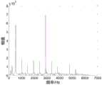
图3是系统振动信号的进行快速傅里叶变换结果图;Fig. 3 is the result graph of carrying out fast Fourier transform of system vibration signal;
图4是信号采集所得的特征曲线示意图;Fig. 4 is the characteristic curve schematic diagram obtained by signal acquisition;
图5是模糊控制器框图;Fig. 5 is the block diagram of fuzzy controller;
图6是控制过程中控制量的变化示意图。FIG. 6 is a schematic diagram of the change of the control amount during the control process.
具体实施方式Detailed ways
实施例1:Example 1:
以下结合附图对本发明的技术方案进一步详细说明。The technical solutions of the present invention are further described in detail below with reference to the accompanying drawings.
如图1所示的面向易变形结构铣削加工的机器人触觉伺服控制的系统,该系统包括装有铣削刀具的铣削机器人,加速度计传感器阵列模块、通信模块、控制器、电机控制模块和上位机:铣削加工的振动信号通过加速度计传感器阵列模块采集后由通信模块传输给控制器,控制器执行控制算法生成结果传入电机驱动模块,再由电机驱动模块控制机器人运动以满足铣削深度保持不变,于此同时控制器还将传输至上位机,上位机实时显示铣削状态并可随时发送指令控制机器人的运行与停止。As shown in Figure 1, the robot tactile servo control system for the milling of deformable structures includes a milling robot equipped with a milling tool, an accelerometer sensor array module, a communication module, a controller, a motor control module and a host computer: The vibration signal of milling processing is collected by the accelerometer sensor array module and then transmitted to the controller by the communication module. The controller executes the control algorithm to generate the result and transmits it to the motor drive module, and then the motor drive module controls the motion of the robot to keep the milling depth unchanged. At the same time, the controller will also be transmitted to the host computer, and the host computer can display the milling status in real time and can send commands to control the operation and stop of the robot at any time.
本发明在上述系统的基础上提出一种面向易变形结构铣削加工的机器人触觉伺服控制方法,所述机器人为装有铣削刀具的机器人,机器人各关节的步进电机分别由不同的驱动器驱动,根据所用铣削刀具的大小本实施例使用了如图2所示的4×4×2的加速度传感器阵列(根据铣削刀具的大小不同可设计不同大小的传感器阵列,例如4×4×n、8×8×n、16×16×n等),单个传感器的尺寸大小为2×2×0.9mm;各个加速度传感器间用电路软板相连,软板能够在很大程度上隔离相邻加速度传感器之间的振动,防止相互干扰;然后将整个阵列嵌入橡胶垫中,利用橡胶的隔振效果防止过大的信号而出现信号截断(参见图2);直接将嵌有加速度传感器阵列的橡胶垫卷成筒状紧包在柱形的铣削刀具表面,以此全面的提取铣削刀具表面各处的加速度信号,并从中选取一个信号最为合适的加速度传感器采集到的数据进行分析,这里最为合适是指在刀具处于空转状态和处于铣削状态时,信号本身的幅值相差最为明显。On the basis of the above system, the present invention proposes a robot tactile servo control method for milling of easily deformable structures. The robot is a robot equipped with a milling tool, and the stepping motors of each joint of the robot are respectively driven by different drivers. The size of the milling tool used This embodiment uses a 4×4×2 acceleration sensor array as shown in Figure 2 (sensor arrays of different sizes can be designed according to the size of the milling tool, such as 4×4×n, 8×8 ×n, 16 × 16 × n, etc.), the size of a single sensor is 2 × 2 × 0.9mm; each acceleration sensor is connected by a circuit soft board, and the soft board can isolate the adjacent acceleration sensors to a large extent. Vibrate to prevent mutual interference; then embed the entire array into a rubber pad, and use the vibration isolation effect of rubber to prevent signal truncation due to excessive signal (see Figure 2); directly roll the rubber pad embedded with the acceleration sensor array into a cylindrical shape It is tightly wrapped on the surface of the cylindrical milling tool, so as to comprehensively extract the acceleration signals from all over the surface of the milling tool, and select the data collected by the acceleration sensor with the most suitable signal for analysis. The amplitude difference of the signal itself is the most obvious when it is in the milling state and in the milling state.
本机器人触觉伺服控制方法分为以下两个阶段:The robot haptic servo control method is divided into the following two stages:
第一阶段为信号采集处理阶段,具体包含以下步骤:The first stage is the signal acquisition and processing stage, which includes the following steps:
铣削易变形结构(例如高密度泡沫板、仿骨材料、薄壁等结构),确认铣削过程中振动信号进行快速傅里叶变换后具有如图3所示的特征,即系统基频的整倍数谐波的幅值较为明显,本例的刀具主轴旋转频率为30000转/分,系统的基频为500HZ,所以图3中的500HZ的倍数频率处存在较为明显的幅值;将加速度传感器阵列包裹在铣削刀具的表面,控制机器人进给,使刀具铣入铣削结构一定深度获取此过程的振动信号,选取一个信号较强且特征明显的加速度计采集到的信号并处理,得到在铣削过程中随铣削深度变化而变化的特征曲线,如图4所示的系统基频三次谐波的幅值,从中选取对应深度的阈值,图4中能够很清晰的看出刀具处于空转时的状态以及与铣削材料接触的瞬间,并且设定对应铣削深度为0.7mm的三次谐波幅值作为阈值,即0.7mm为设定的铣削深度,为1.15×106。Mill easily deformable structures (such as high-density foam boards, bone-like materials, thin-walled structures, etc.), and confirm that the vibration signal during the milling process has the characteristics shown in Figure 3 after fast Fourier transform, that is, the integral multiple of the fundamental frequency of the system The amplitude of harmonics is relatively obvious. In this example, the rotation frequency of the tool spindle is 30,000 rpm, and the fundamental frequency of the system is 500HZ, so there is a relatively obvious amplitude at the multiple frequency of 500HZ in Figure 3; wrap the acceleration sensor array On the surface of the milling tool, control the feed of the robot, so that the tool is milled into the milling structure to a certain depth to obtain the vibration signal of this process, select a signal collected by an accelerometer with strong signal and obvious characteristics and process it, and obtain the vibration signal during the milling process. The characteristic curve that changes with the change of the milling depth, as shown in Figure 4, shows the amplitude of the third harmonic of the fundamental frequency of the system, from which the threshold value of the corresponding depth is selected. In Figure 4, it can be clearly seen that the tool is in the state of idling and the difference between milling and milling. The moment when the material contacts, and the third harmonic amplitude corresponding to the milling depth of 0.7 mm is set as the threshold, that is, 0.7 mm is the set milling depth, which is 1.15×10⁶ .
第二阶段为控制阶段,具体包含以下步骤:The second stage is the control stage, which includes the following steps:
开启控制器实时接收由加速度传感器阵列采集到的加速度信号,并在接收到1024个加速度数据后进行进行快速傅里叶变换,得到对应第一阶段特征曲线的数据,判断此时所处铣削状态,选取不同的控制方案:首先当刀具长时间处于空转状态时,加速机器人进给,使刀具尽快接触到待铣削结构,并在接触的瞬间把速度降至安全范围;当三次谐波的幅值第一次到达设定阈值后,进入正式铣削过程,即平面铣削过程,此时使用如图5所示的控制框图进行运动控制,将三次谐波的幅值和设定阈值作比较得出偏差E与偏差的导数DE,并输入到模糊控制器执行的控制算法中,通过模糊化、解模糊化处理,得到模糊输出在0的上下波动,波动范围大致为±4×10⁵,如图6所示,将此输出缩小1000倍得到适合步进电机的最佳运行速度,也就是使得电机能前后运动,且运动幅度并不大,维持在0.2mm/s的速度下,不会破坏铣削质量。总而言之,此阶段由控制器上的电机控制模块对机器人进行运动控制,使得整个铣削过程被不断修正,在此过程中会遇到如结构形变、位移或表面凹凸不平等干扰,这些干扰最终都会转变为刀具所处铣削深度的变化,方案会使得机器人不断运动以修正这些干扰所带来的影响,使整个铣削过程中刀具所处的铣削深度基本保持不变,例如当结构在铣削中发生远离刀头的形变,此时在三次谐波的幅值上便会存在一个衰减,产生负偏差,控制算法会生成一个正向的前进速度使得刀具前进,维持铣削深度。Turn on the controller to receive the acceleration signal collected by the acceleration sensor array in real time, and perform fast Fourier transform after receiving 1024 acceleration data to obtain the data corresponding to the characteristic curve of the first stage, and determine the milling state at this time. Select different control schemes: first, when the tool is in an idling state for a long time, the robot feed is accelerated, so that the tool contacts the structure to be milled as soon as possible, and the speed is reduced to a safe range at the moment of contact; After reaching the set threshold once, it enters the formal milling process, that is, the plane milling process. At this time, the control block diagram shown in Figure 5 is used for motion control, and the amplitude of the third harmonic is compared with the set threshold to obtain the deviation E. The derivative DE of the deviation is input into the control algorithm executed by the fuzzy controller. Through fuzzification and defuzzification, the fuzzy output fluctuates around 0, and the fluctuation range is roughly ±4×10⁵ , as shown in Figure 6 As shown in the figure, reducing this output by 1000 times can get the best running speed suitable for the stepping motor, that is, the motor can move back and forth, and the movement range is not large, and the milling quality will not be damaged when the speed is maintained at 0.2mm/s . All in all, at this stage, the motor control module on the controller controls the motion of the robot, so that the entire milling process is continuously corrected. During this process, disturbances such as structural deformation, displacement or surface unevenness will be encountered, and these disturbances will eventually be transformed. In order to change the milling depth of the tool, the solution will make the robot move continuously to correct the influence of these disturbances, so that the milling depth of the tool remains basically unchanged during the entire milling process. For example, when the structure is far away from the tool during milling The deformation of the head, at this time, there will be an attenuation in the amplitude of the third harmonic, resulting in a negative deviation, and the control algorithm will generate a positive forward speed to make the tool advance and maintain the milling depth.
Claims (5)
Translated fromChinesePriority Applications (1)
| Application Number | Priority Date | Filing Date | Title |
|---|---|---|---|
| CN202010221318.8ACN111283476B (en) | 2020-03-26 | 2020-03-26 | Robot touch servo control method for milling of easily-deformed structure |
Applications Claiming Priority (1)
| Application Number | Priority Date | Filing Date | Title |
|---|---|---|---|
| CN202010221318.8ACN111283476B (en) | 2020-03-26 | 2020-03-26 | Robot touch servo control method for milling of easily-deformed structure |
Publications (2)
| Publication Number | Publication Date |
|---|---|
| CN111283476Atrue CN111283476A (en) | 2020-06-16 |
| CN111283476B CN111283476B (en) | 2021-09-17 |
Family
ID=71023951
Family Applications (1)
| Application Number | Title | Priority Date | Filing Date |
|---|---|---|---|
| CN202010221318.8AActiveCN111283476B (en) | 2020-03-26 | 2020-03-26 | Robot touch servo control method for milling of easily-deformed structure |
Country Status (1)
| Country | Link |
|---|---|
| CN (1) | CN111283476B (en) |
Cited By (4)
| Publication number | Priority date | Publication date | Assignee | Title |
|---|---|---|---|---|
| CN112040369A (en)* | 2020-09-09 | 2020-12-04 | 南开大学 | Microphone array system capable of realizing bone milling depth monitoring based on milling sound |
| CN116457143A (en)* | 2020-09-29 | 2023-07-18 | 西门子股份公司 | Method for identifying the state of a machine tool, at least one machine tool or at least one workpiece machined in a machine tool off-line and/or on-line |
| CN119526276A (en)* | 2025-01-22 | 2025-02-28 | 浙江安统汽车部件有限公司 | A Grinding Control System for Automobile Parts |
| CN120326304A (en)* | 2025-06-19 | 2025-07-18 | 宜宾宏一机械有限责任公司 | A processing control method and processing fixing device suitable for thin-walled shell parts |
Citations (9)
| Publication number | Priority date | Publication date | Assignee | Title |
|---|---|---|---|---|
| JPS6125206A (en)* | 1984-07-12 | 1986-02-04 | Fanuc Ltd | Tool position setting system of robot |
| US5803886A (en)* | 1996-02-24 | 1998-09-08 | Chiron-Werke Gmbh & Co. Kg | Workpiece gripper |
| CN104596681A (en)* | 2013-10-31 | 2015-05-06 | 精工爱普生株式会社 | Sensor device, force detecting device, robot, electronic component conveying apparatus, electronic component inspecting apparatus, and component machining apparatus |
| CN104759943A (en)* | 2015-03-30 | 2015-07-08 | 北京工业大学 | Device and method for detecting gear shape and performance |
| CN105324219A (en)* | 2013-06-24 | 2016-02-10 | 红木机器人有限责任公司 | Modular reconfigurable workcell for quick connection of peripherals |
| CN107530878A (en)* | 2015-05-13 | 2018-01-02 | 整形工具股份有限公司 | Systems, methods and apparatus for guided tools |
| CN208826187U (en)* | 2018-10-13 | 2019-05-07 | 江西铃格有色金属加工有限公司 | For part machining feature detection device in three coordinate numerical control processings |
| CN110091215A (en)* | 2019-05-08 | 2019-08-06 | 北京理工大学 | A kind of real-time monitoring Milling Force, the wireless transmission intelligence knife handle detection system of vibration |
| CN110366478A (en)* | 2017-02-28 | 2019-10-22 | 费尔有限公司 | Articulated arm robot and method for machining workpieces by means of articulated arm robot |
- 2020
- 2020-03-26CNCN202010221318.8Apatent/CN111283476B/enactiveActive
Patent Citations (9)
| Publication number | Priority date | Publication date | Assignee | Title |
|---|---|---|---|---|
| JPS6125206A (en)* | 1984-07-12 | 1986-02-04 | Fanuc Ltd | Tool position setting system of robot |
| US5803886A (en)* | 1996-02-24 | 1998-09-08 | Chiron-Werke Gmbh & Co. Kg | Workpiece gripper |
| CN105324219A (en)* | 2013-06-24 | 2016-02-10 | 红木机器人有限责任公司 | Modular reconfigurable workcell for quick connection of peripherals |
| CN104596681A (en)* | 2013-10-31 | 2015-05-06 | 精工爱普生株式会社 | Sensor device, force detecting device, robot, electronic component conveying apparatus, electronic component inspecting apparatus, and component machining apparatus |
| CN104759943A (en)* | 2015-03-30 | 2015-07-08 | 北京工业大学 | Device and method for detecting gear shape and performance |
| CN107530878A (en)* | 2015-05-13 | 2018-01-02 | 整形工具股份有限公司 | Systems, methods and apparatus for guided tools |
| CN110366478A (en)* | 2017-02-28 | 2019-10-22 | 费尔有限公司 | Articulated arm robot and method for machining workpieces by means of articulated arm robot |
| CN208826187U (en)* | 2018-10-13 | 2019-05-07 | 江西铃格有色金属加工有限公司 | For part machining feature detection device in three coordinate numerical control processings |
| CN110091215A (en)* | 2019-05-08 | 2019-08-06 | 北京理工大学 | A kind of real-time monitoring Milling Force, the wireless transmission intelligence knife handle detection system of vibration |
Cited By (5)
| Publication number | Priority date | Publication date | Assignee | Title |
|---|---|---|---|---|
| CN112040369A (en)* | 2020-09-09 | 2020-12-04 | 南开大学 | Microphone array system capable of realizing bone milling depth monitoring based on milling sound |
| CN112040369B (en)* | 2020-09-09 | 2022-05-17 | 南开大学 | Microphone array system capable of realizing bone milling depth monitoring based on milling sound |
| CN116457143A (en)* | 2020-09-29 | 2023-07-18 | 西门子股份公司 | Method for identifying the state of a machine tool, at least one machine tool or at least one workpiece machined in a machine tool off-line and/or on-line |
| CN119526276A (en)* | 2025-01-22 | 2025-02-28 | 浙江安统汽车部件有限公司 | A Grinding Control System for Automobile Parts |
| CN120326304A (en)* | 2025-06-19 | 2025-07-18 | 宜宾宏一机械有限责任公司 | A processing control method and processing fixing device suitable for thin-walled shell parts |
Also Published As
| Publication number | Publication date |
|---|---|
| CN111283476B (en) | 2021-09-17 |
Similar Documents
| Publication | Publication Date | Title |
|---|---|---|
| CN111283476A (en) | Robot touch servo control method for milling of easily-deformed structure | |
| US8457787B2 (en) | Method and control device for targeted reaction in the event of a contact between a machine element of a machine and an object | |
| JP3025421B2 (en) | Abnormality detection device for control system | |
| US7850406B2 (en) | Method for setting working origin and machine tool for implementing the same | |
| DE102019102859B4 (en) | working robot system | |
| Wu et al. | Precision machining without precise machinery | |
| CN105033739B (en) | Device for opening/closing door and system of processing | |
| JPH01252340A (en) | Machining control device employing force sensor | |
| CN110103201B (en) | Work robot system | |
| CN110174873A (en) | Servocontrol device | |
| CN113910106B (en) | Grinding force control method and grinding machine based on same | |
| CN101852671B (en) | Automatic displacement simulation loading device and static stiffness distribution detection method for CNC lathe | |
| Frumusanu et al. | Development of a stability intelligent control system for turning | |
| CN109687771A (en) | Control device | |
| Brüning et al. | Simulation based planning of machining processes with industrial robots | |
| Diez et al. | Dynamic analysis of a piezoelectric system to compensate for workpiece deformations in flexible milling | |
| CN1326005C (en) | Method and apparatus for controlling a machine tool | |
| CN104871101B (en) | The method that workpiece is processed for material removal | |
| Kouguchi et al. | Machine-Learning-Based Model Parameter Identification for Cutting Force Estimation | |
| CN114851189B (en) | Control method of cooperative robot and cooperative robot | |
| Pan et al. | Robotic machining from programming to process control | |
| CN105643339A (en) | Numerically controlled machine tool for direct and manual operation of movable part | |
| JP3787481B2 (en) | Method and apparatus for detecting load of cutting tool in machine tool | |
| US20180364681A1 (en) | Numerical controller | |
| EP4291960B1 (en) | Methods and systems for adapting a feed rate of a feed control on numerically controlled machine tools |
Legal Events
| Date | Code | Title | Description |
|---|---|---|---|
| PB01 | Publication | ||
| PB01 | Publication | ||
| SE01 | Entry into force of request for substantive examination | ||
| SE01 | Entry into force of request for substantive examination | ||
| GR01 | Patent grant | ||
| GR01 | Patent grant |