CN111282087A - Medical liquid level off-limit alarm device - Google Patents
Medical liquid level off-limit alarm deviceDownload PDFInfo
- Publication number
- CN111282087A CN111282087ACN202010193276.1ACN202010193276ACN111282087ACN 111282087 ACN111282087 ACN 111282087ACN 202010193276 ACN202010193276 ACN 202010193276ACN 111282087 ACN111282087 ACN 111282087A
- Authority
- CN
- China
- Prior art keywords
- clamping
- groups
- air
- controller
- shell
- Prior art date
- Legal status (The legal status is an assumption and is not a legal conclusion. Google has not performed a legal analysis and makes no representation as to the accuracy of the status listed.)
- Granted
Links
Images


Classifications
- A—HUMAN NECESSITIES
- A61—MEDICAL OR VETERINARY SCIENCE; HYGIENE
- A61M—DEVICES FOR INTRODUCING MEDIA INTO, OR ONTO, THE BODY; DEVICES FOR TRANSDUCING BODY MEDIA OR FOR TAKING MEDIA FROM THE BODY; DEVICES FOR PRODUCING OR ENDING SLEEP OR STUPOR
- A61M5/00—Devices for bringing media into the body in a subcutaneous, intra-vascular or intramuscular way; Accessories therefor, e.g. filling or cleaning devices, arm-rests
- A61M5/14—Infusion devices, e.g. infusing by gravity; Blood infusion; Accessories therefor
- A61M5/168—Means for controlling media flow to the body or for metering media to the body, e.g. drip meters, counters ; Monitoring media flow to the body
- A61M5/16831—Monitoring, detecting, signalling or eliminating infusion flow anomalies
- A61M5/1684—Monitoring, detecting, signalling or eliminating infusion flow anomalies by detecting the amount of infusate remaining, e.g. signalling end of infusion
- A—HUMAN NECESSITIES
- A61—MEDICAL OR VETERINARY SCIENCE; HYGIENE
- A61M—DEVICES FOR INTRODUCING MEDIA INTO, OR ONTO, THE BODY; DEVICES FOR TRANSDUCING BODY MEDIA OR FOR TAKING MEDIA FROM THE BODY; DEVICES FOR PRODUCING OR ENDING SLEEP OR STUPOR
- A61M5/00—Devices for bringing media into the body in a subcutaneous, intra-vascular or intramuscular way; Accessories therefor, e.g. filling or cleaning devices, arm-rests
- A61M5/14—Infusion devices, e.g. infusing by gravity; Blood infusion; Accessories therefor
- A61M5/1414—Hanging-up devices
- A61M5/1415—Stands, brackets or the like for supporting infusion accessories
- A—HUMAN NECESSITIES
- A61—MEDICAL OR VETERINARY SCIENCE; HYGIENE
- A61M—DEVICES FOR INTRODUCING MEDIA INTO, OR ONTO, THE BODY; DEVICES FOR TRANSDUCING BODY MEDIA OR FOR TAKING MEDIA FROM THE BODY; DEVICES FOR PRODUCING OR ENDING SLEEP OR STUPOR
- A61M5/00—Devices for bringing media into the body in a subcutaneous, intra-vascular or intramuscular way; Accessories therefor, e.g. filling or cleaning devices, arm-rests
- A61M5/14—Infusion devices, e.g. infusing by gravity; Blood infusion; Accessories therefor
- A61M5/1414—Hanging-up devices
- A61M5/1417—Holders or handles for hanging up infusion containers
- A—HUMAN NECESSITIES
- A61—MEDICAL OR VETERINARY SCIENCE; HYGIENE
- A61M—DEVICES FOR INTRODUCING MEDIA INTO, OR ONTO, THE BODY; DEVICES FOR TRANSDUCING BODY MEDIA OR FOR TAKING MEDIA FROM THE BODY; DEVICES FOR PRODUCING OR ENDING SLEEP OR STUPOR
- A61M5/00—Devices for bringing media into the body in a subcutaneous, intra-vascular or intramuscular way; Accessories therefor, e.g. filling or cleaning devices, arm-rests
- A61M5/14—Infusion devices, e.g. infusing by gravity; Blood infusion; Accessories therefor
- A61M5/168—Means for controlling media flow to the body or for metering media to the body, e.g. drip meters, counters ; Monitoring media flow to the body
- A61M5/16804—Flow controllers
- A—HUMAN NECESSITIES
- A61—MEDICAL OR VETERINARY SCIENCE; HYGIENE
- A61M—DEVICES FOR INTRODUCING MEDIA INTO, OR ONTO, THE BODY; DEVICES FOR TRANSDUCING BODY MEDIA OR FOR TAKING MEDIA FROM THE BODY; DEVICES FOR PRODUCING OR ENDING SLEEP OR STUPOR
- A61M5/00—Devices for bringing media into the body in a subcutaneous, intra-vascular or intramuscular way; Accessories therefor, e.g. filling or cleaning devices, arm-rests
- A61M5/14—Infusion devices, e.g. infusing by gravity; Blood infusion; Accessories therefor
- A61M5/168—Means for controlling media flow to the body or for metering media to the body, e.g. drip meters, counters ; Monitoring media flow to the body
- A61M5/16877—Adjusting flow; Devices for setting a flow rate
- A—HUMAN NECESSITIES
- A61—MEDICAL OR VETERINARY SCIENCE; HYGIENE
- A61M—DEVICES FOR INTRODUCING MEDIA INTO, OR ONTO, THE BODY; DEVICES FOR TRANSDUCING BODY MEDIA OR FOR TAKING MEDIA FROM THE BODY; DEVICES FOR PRODUCING OR ENDING SLEEP OR STUPOR
- A61M2205/00—General characteristics of the apparatus
- A61M2205/18—General characteristics of the apparatus with alarm
Landscapes
- Health & Medical Sciences (AREA)
- Vascular Medicine (AREA)
- Engineering & Computer Science (AREA)
- Anesthesiology (AREA)
- Biomedical Technology (AREA)
- Heart & Thoracic Surgery (AREA)
- Hematology (AREA)
- Life Sciences & Earth Sciences (AREA)
- Animal Behavior & Ethology (AREA)
- General Health & Medical Sciences (AREA)
- Public Health (AREA)
- Veterinary Medicine (AREA)
- Physics & Mathematics (AREA)
- Fluid Mechanics (AREA)
- Infusion, Injection, And Reservoir Apparatuses (AREA)
Abstract
Description
Translated fromChinese技术领域technical field
本发明涉及液位越限报警技术领域,具体是一种医用液位越限报警装置。The invention relates to the technical field of liquid level over-limit alarm, in particular to a medical liquid level over-limit alarm device.
背景技术Background technique
当病人在医院输液时,通常需要护士或家人的看护,当液体输完时,如果未能及时发现,会给病人带来很大的麻烦甚至造成生命危险。When the patient is in the hospital for infusion, he usually needs the care of nurses or family members. When the infusion of the liquid is finished, if it is not found in time, it will bring great trouble to the patient and even cause danger to life.
目前医院在跟病人输液(打吊针或打点 滴)大多都是采用吊挂式垂直压降的方法,采用输液网套对输液瓶进行吊挂,不仅在寻找合适的输液网套时会浪费一些时间,而且也只有在输液瓶放入输液网套后才能将输液器扎入输液瓶中,整个过程不仅浪费时间,而且也相对繁琐,并且随着长时间的使用,输液网套还会出现老化,无法使用的情况。At present, most hospitals use the hanging vertical pressure drop method for infusion with patients (suspension or drip), and the infusion net sleeve is used to hang the infusion bottle, which not only wastes some time when looking for a suitable infusion net sleeve , and the infusion set can only be inserted into the infusion bottle after the infusion bottle is put into the infusion net. Unusable situation.
而且输液时还有一个重要的问题是:当输液瓶内滴液用尽时, 需要请护士拔针或续瓶,稍不注意,则血液可能反从血管倒流至滴液细管中,若此时需要续 瓶,则空气进入滴管,难以排除,病人还可能需要二次打针,增加了护士的工作强度的同时 病人还要忍受再次打针带来的痛苦;如不小心让空气进入血管,将对人体产生很不利的影 响,严重的可能引起医疗事故或医患矛盾。为此,在滴液瓶中所剩滴液不多时,病人或陪同人员需要随时观察,病人无法得到很好的休息,而陪同人员也费尽心神。In addition, there is another important problem during infusion: when the drip in the infusion bottle is used up, you need to ask the nurse to pull out the needle or refill the bottle. If you are not careful, the blood may flow back from the blood vessel to the drip tube. When the bottle needs to be refilled, the air will enter the dropper, which is difficult to eliminate. The patient may also need a second injection, which increases the work intensity of the nurse and the patient has to endure the pain caused by another injection. It has a very adverse effect on the human body, and may cause serious medical accidents or conflicts between doctors and patients. For this reason, when there are not many drops left in the drip bottle, the patient or the accompanying person needs to observe at any time, the patient cannot get a good rest, and the accompanying person is also exhausted.
所以,人们需要一种医用液位越限报警装置来解决上述问题。Therefore, people need a medical liquid level out-of-limit alarm device to solve the above problems.
发明内容SUMMARY OF THE INVENTION
本发明的目的在于提供一种医用液位越限报警装置,以解决现有技术中提出的问题。The purpose of the present invention is to provide a medical liquid level over-limit alarm device to solve the problems raised in the prior art.
为实现上述目的,本发明提供如下技术方案:一种医用液位越限报警装置,该越限报警装置包括支架、套壳、夹持机构、夹紧机构、控制系统,其特征在于:所述套壳设置在支架上,套壳从上至下依次设置有夹持机构、夹紧机构,套壳上设置有控制系统,所述夹持机构通过输液瓶的重力对输液瓶进行夹持,所述夹紧机构通过输液瓶的重力对输液器进行收缩夹紧,所述控制系统对输液瓶中的药液位置进行监测,控制系统控制夹紧机构对输液器的收缩夹紧。只需要将输液瓶放置在夹持机构上,夹持机构就会通过输液瓶的重力对输液瓶进行夹持,相对于传统的将输液瓶放置在输液网套中进行倒挂的方式,此夹持机构的夹持方式仅通过输液瓶的重力就可以实现,此夹持方式既简单又方便,而且夹紧机构在夹持机构往下运动时,通过空气注入,使得夹紧机构打开,使得夹紧机构可以对输液器进行收缩夹紧,当控制系统根据病人等待时间,需要对输液器的流速进行控制时,只需要将夹紧机构中的空气进行释放,夹紧机构就可以对输液器进行流速控制,使得病人可以等到医护人员的处理。In order to achieve the above purpose, the present invention provides the following technical solutions: a medical liquid level over-limit alarm device, the over-limit alarm device includes a bracket, a casing, a clamping mechanism, a clamping mechanism, and a control system, characterized in that: the The sleeve is arranged on the bracket, the sleeve is provided with a clamping mechanism and a clamping mechanism in sequence from top to bottom, and a control system is arranged on the sleeve, and the clamping mechanism clamps the infusion bottle by the gravity of the infusion bottle, so The clamping mechanism shrinks and clamps the infusion set by the gravity of the infusion bottle, the control system monitors the position of the medicinal liquid in the infusion bottle, and the control system controls the clamping mechanism to shrink and clamp the infusion set. It is only necessary to place the infusion bottle on the clamping mechanism, and the clamping mechanism will clamp the infusion bottle by the gravity of the infusion bottle. The clamping method of the mechanism can be realized only by the gravity of the infusion bottle. This clamping method is simple and convenient, and when the clamping mechanism moves down, the clamping mechanism is injected by air, so that the clamping mechanism is opened, so that the clamping mechanism is opened. The mechanism can shrink and clamp the infusion set. When the control system needs to control the flow rate of the infusion set according to the waiting time of the patient, it only needs to release the air in the clamping mechanism, and the clamping mechanism can control the flow rate of the infusion set. control, so that the patient can wait for the treatment of the medical staff.
作为优选技术方案,所述夹持机构包括至少两组夹持板、至少四组伸缩杆、至少两组空气压缩器,四组所述伸缩杆对称设置在套壳上,伸缩杆一端与夹持板固定,伸缩杆另一端与空气压缩器滑动连接;所述夹紧机构包括夹紧壳、若干组夹紧板,所述夹紧壳设置在套壳上,夹紧壳中设置有若干组夹紧板;所述控制系统包括控制器、图像采集器、无线收发器,所述控制器分别与图像采集器、无线收发器电性连接,所述图像采集器对输液瓶中的药液位置进行图像采集,所述控制器对图像进行数据处理;所述夹紧壳与空气压缩器的出气口固定,所述控制器对夹紧壳中的空气量进行控制。两组夹持板与套壳相互配合对输液瓶进行夹持,使其垂直吊挂在支架上,伸缩杆对夹持板进行安装支撑并带着夹持板在套壳上滑动,空气压缩器为夹紧机构提供所需要的空气,夹紧壳对夹紧板的安装提供支撑,夹紧板在空气注入时往夹紧壳内收缩,使输液器可以进行夹紧机构的中心位置,当空气释放后,夹紧板在夹紧弹簧的弹性势能的作用下对夹紧机构中心的输液器进行挤压,使输液器进行收缩,控制器对数据进行分析处理,图像采集器对输液瓶中药液的位置进行图像采集,无线收发器为设备之间的无线连接提供支撑。As a preferred technical solution, the clamping mechanism includes at least two groups of clamping plates, at least four groups of telescopic rods, and at least two groups of air compressors. The four groups of telescopic rods are symmetrically arranged on the casing, and one end of the telescopic rods is connected to the clamping The plate is fixed, and the other end of the telescopic rod is slidably connected with the air compressor; the clamping mechanism includes a clamping shell and several groups of clamping plates, the clamping shell is arranged on the sleeve, and several groups of clamps are arranged in the clamping shell The control system includes a controller, an image collector, and a wireless transceiver, the controller is electrically connected to the image collector and the wireless transceiver, respectively, and the image collector monitors the position of the medicinal liquid in the infusion bottle. Image acquisition, the controller performs data processing on the image; the clamping shell is fixed with the air outlet of the air compressor, and the controller controls the air volume in the clamping shell. The two sets of clamping plates and the sleeve cooperate with each other to clamp the infusion bottle, so that it hangs vertically on the bracket. The telescopic rod installs and supports the clamping plate and slides the clamping plate on the sleeve. The air compressor Provide the required air for the clamping mechanism, the clamping shell provides support for the installation of the clamping plate, and the clamping plate shrinks into the clamping shell when the air is injected, so that the infusion set can move to the center of the clamping mechanism. After the release, the clamping plate squeezes the infusion set in the center of the clamping mechanism under the action of the elastic potential energy of the clamping spring, so that the infusion set shrinks, the controller analyzes and processes the data, and the image collector analyzes the traditional Chinese medicine in the infusion bottle. The position of the liquid is used for image acquisition, and the wireless transceiver provides support for the wireless connection between the devices.
作为优选技术方案,所述套壳上对称设置有两组滑槽,两组所述滑槽一端向下倾斜60°,滑槽中设置有齿轮条,四组中的两组所述伸缩杆分别设置在一组滑槽中,所述伸缩杆与滑槽滑动连接,两组中的一组所述伸缩杆的一端贯穿滑槽,所述伸缩杆贯穿滑槽的一端与空气压缩器滑动连接,四组所述伸缩杆上均固定有齿轮,所述齿轮与齿轮条进行齿轮传动,四组中的两组所述伸缩杆的另一端分别与一组所述夹持板固定,两组所述夹持板通过伸缩杆与滑槽的相互配合实现在套壳上滑动。滑槽为伸缩杆在套壳上的滑动提供通道,滑槽倾斜向下60°,使伸缩杆在受到夹持板的重力下刚好移动到滑槽底端,齿轮条为齿轮的齿轮传动提供支撑,齿轮与齿轮条进行齿轮传动,齿轮带动丝杆进行旋转,为丝杆的转动提供动力。As a preferred technical solution, two sets of runners are symmetrically arranged on the casing, one end of the two sets of runners is inclined downward by 60°, a gear rack is arranged in the runners, and the two sets of the telescopic rods in the four sets are respectively The telescopic rod is arranged in a set of chute, the telescopic rod is slidably connected with the chute, one end of the telescopic rod in one of the two groups penetrates the chute, and one end of the telescopic rod passes through the chute and is slidably connected to the air compressor, Gears are fixed on the four sets of telescopic rods, and the gears and gear racks are geared for gear transmission. The other ends of the two sets of telescopic rods in the four sets are respectively The clamping plate slides on the casing through the mutual cooperation of the telescopic rod and the chute. The chute provides a channel for the sliding of the telescopic rod on the casing. The chute is inclined downward at 60°, so that the telescopic rod just moves to the bottom of the chute under the gravity of the clamping plate, and the gear rack provides support for the gear transmission of the gear. , The gear and the gear rack are geared, and the gear drives the screw to rotate, providing power for the rotation of the screw.
作为优选技术方案,所述伸缩杆包括滑杆、丝杆、伸缩壳、连接杆,所述伸缩壳分为左半部分和右半部分,伸缩壳的左板部分与丝杆的一端进行丝杆传动,伸缩壳的右半部分与连接杆滑动连接,所述伸缩壳的右半部分内部设置有弹簧,所述丝杆上设置有齿轮,丝杆的另一端与滑杆转动连接,所述滑杆上设置有滑柱,所述空气压缩器的上端面设置有柱槽,所述滑柱设置在柱槽内,所述滑杆在伸缩杆向下倾斜滑动时通过滑柱对空气压缩器进行空气压缩。滑杆与空气压缩器进行滑动连接,滑杆在丝杆的带动下往下运动时,滑杆从空气压缩器的一端滑动到另一端,使空气压缩器中的空气注入到夹紧机构中,丝杆与伸缩壳的左半部分进行丝杆传动,当丝杆在齿轮的带动下进行旋转时,伸缩壳受丝杆转动的影响往外移动,当丝杆在齿轮的带动下移动到滑槽下端时,伸缩壳刚好伸缩套壳并于夹持板接触,伸缩壳的另一端滑动安装有连接杆,而且在与连接杆之间还安装有弹簧,连接杆一开始在弹簧在作用下伸处伸缩壳,使两组夹持板之间形成的夹持空间比较小,方便对小规格尺寸的输液瓶进行夹持,当放入大规格尺寸的输液瓶时,连接杆在夹持板的作用下往伸缩壳内收缩,以此方便对大规格尺寸的输液瓶进行夹持。As a preferred technical solution, the telescopic rod includes a sliding rod, a screw rod, a telescopic shell, and a connecting rod. The telescopic shell is divided into a left half and a right half, and the left plate part of the telescopic shell is connected with one end of the screw rod. Transmission, the right half of the telescopic shell is slidably connected with the connecting rod, the right half of the telescopic shell is provided with a spring, the screw rod is provided with a gear, the other end of the screw rod is rotatably connected with the sliding rod, the sliding The rod is provided with a sliding column, the upper end surface of the air compressor is provided with a column groove, and the sliding column is arranged in the column groove. Air compression. The sliding rod is slidably connected with the air compressor. When the sliding rod moves downwards driven by the screw rod, the sliding rod slides from one end of the air compressor to the other end, so that the air in the air compressor is injected into the clamping mechanism. The lead screw and the left half of the telescopic casing are driven by the lead screw. When the lead screw rotates under the drive of the gear, the telescopic casing moves outward under the influence of the rotation of the lead screw. When the lead screw is driven by the gear, it moves to the lower end of the chute. When the telescopic casing is just telescopic and in contact with the clamping plate, the other end of the telescopic casing is slidably installed with a connecting rod, and a spring is also installed between the telescopic casing and the connecting rod. shell, so that the clamping space formed between the two groups of clamping plates is relatively small, which is convenient for clamping small-sized infusion bottles. When a large-sized infusion bottle is placed, the connecting rod is under the action of the clamping plate It shrinks into the telescopic shell, so as to facilitate the clamping of large-sized infusion bottles.
作为优选技术方案,两组所述夹持板呈扇形结构,所述夹持板的下端设置有承载板,所述承载板为扇形结构,承载板呈坡体结构,承载板的向下倾斜的坡度为10°,承载板上设置在滑轮条。两组夹持板呈扇形结构,刚好可以与套壳相互配合形成一个完整的圆形夹持空间,方便对输液瓶进行安全的夹持,承载板对输液瓶进行支撑并进行力量传递,承载板在倾斜向下的坡体上安装有滑轮条,通过倾斜向下的坡体以及滑轮条可以使得承载板在获取输液瓶重力的同时又能减少与输液瓶之间的摩擦,承载板将输液瓶上的重力通过夹持板传递到伸缩杆上,使得伸缩杆可以在滑槽内向下滑动。As a preferred technical solution, the two groups of the clamping plates are in a fan-shaped structure, the lower ends of the clamping plates are provided with a bearing plate, the bearing plates are in a fan-shaped structure, the bearing plates are in a slope structure, and the downwardly inclined bearing plates The slope is 10°, and the carrier plate is set on the pulley bar. The two sets of clamping plates have a fan-shaped structure, which can just cooperate with the casing to form a complete circular clamping space, which is convenient for safe clamping of the infusion bottle. The bearing plate supports the infusion bottle and transmits power. The bearing plate A pulley bar is installed on the inclined downward slope. The inclined downward slope and the pulley bar can make the bearing plate obtain the gravity of the infusion bottle while reducing friction with the infusion bottle. The gravitational force is transmitted to the telescopic rod through the clamping plate, so that the telescopic rod can slide down in the chute.
作为优选技术方案,所述夹紧壳上设置有若干组气槽,夹紧壳在若干组所述气槽的一端设置有弧形气槽,夹紧壳上设置有三组气孔,其中两组所述气孔为进气孔,一组所述气孔为出气孔,所述夹紧壳在进气孔的进气端设置有单向阀,夹紧壳在出气孔的出气端设置有电控阀,所述电控阀与控制器电性连接,若干组所述夹紧板的下端面设置有气动板,所述气动板位于气槽内,气动板与气槽之间设置有夹紧弹簧,若干组所述夹紧板通过气动板与气槽实现在夹紧壳内滑动。弧形气槽方便空气压缩器将其内部的空气注入到气槽中,气槽为夹紧板收缩到夹紧壳内提供动力,进气孔为空气注入提供通道,出气孔为气体的释放提供通道,单向阀使空气只能流入不能流出,电控阀与控制器电性连接,通过控制器的控制将气槽中的空气释放出去,使得夹紧板可以在夹紧弹簧的弹性势能下伸出夹紧壳并对输液器进行流速控制。As a preferred technical solution, the clamping shell is provided with several groups of air grooves, the clamping shell is provided with arc-shaped air grooves at one end of the several groups of the air grooves, and the clamping shell is provided with three groups of air holes, of which two groups are The air holes are air inlet holes, and a group of the air holes are air outlet holes. The electric control valve is electrically connected with the controller, pneumatic plates are arranged on the lower end surfaces of several groups of the clamping plates, the pneumatic plates are located in the air grooves, and clamping springs are arranged between the pneumatic plates and the air grooves. The clamping plate is slid in the clamping shell through the pneumatic plate and the air groove. The arc-shaped air groove is convenient for the air compressor to inject the air inside it into the air groove, the air groove provides the power for the clamping plate to shrink into the clamping shell, the air inlet provides a channel for air injection, and the air outlet provides the air release. The channel, the one-way valve allows the air to only flow in but not flow out. The electric control valve is electrically connected to the controller, and the air in the air groove is released through the control of the controller, so that the clamping plate can be under the elastic potential energy of the clamping spring. Extend the clamping shell and apply flow control to the infusion set.
作为优选技术方案,所述控制器包括总控制器和分控制器,所述分控制器设置在套壳中,所述总控制器设置在医院的输液室内,所述图像采集器对输液瓶中药液的位置进行图像采集,并将采集的图像传送到分控制器中,分控制器对图像进行数据计算,可以算出输液速度,并根据药液的位置以及输液速度计算出药液输完的时间,所述分控制器通过无线收发器将药液输完的时间传输到总控制器中,所述总控制器根据每个分控制器传输的时间,进行时间排序并建立一个时间集合T={t1、t2、t3、…tn},总控制器通过无线收发器将时间排序发送到医护人员的移动设备中,医护人员根据时间排序对相应的病人进行处理。As a preferred technical solution, the controller includes a main controller and a sub-controller, the sub-controller is arranged in the casing, the main controller is arranged in the infusion room of the hospital, and the image collector is connected to the infusion bottle. The position of the liquid medicine is imaged, and the collected image is transmitted to the sub-controller. The sub-controller calculates the data of the image, and can calculate the infusion speed. Time, the sub-controller transmits the time when the medicinal liquid is finished by the wireless transceiver to the overall controller, and the overall controller carries out time sorting according to the time of each sub-controller transmission and establishes a time set T= {t1 , t2 , t3 , ... tn }, the general controller sends the time sequence to the mobile device of the medical staff through the wireless transceiver, and the medical staff processes the corresponding patients according to the time sequence.
作为优选技术方案,所述总控制器通过无线收发器与医护人员的移动设备连接,并获取医护人员的所在位置,根据医护人员距离需要处理的病人之间的距离,以及医护人员的移动速度,计算得到一个新的时间集合T1={a1、a2、a3、…an},此时间集合T1 为医护人员到需要处理的病人之间的时间集合,所述总控制器将集合T和集合T1中元素向对应的时间进行相加,得到另外一个全新的时间集合T2={P1、P2、P3、…Pn},其中Pn=tn+an,此时间集合T2为医护人员对所需处理病人的总的时间集合,所述总控制器对下一个需要处理的病人的等待时间进行公式计算,并通过无线收发器将等待时间传输到相应的支架中的分控制器内。As a preferred technical solution, the general controller is connected with the mobile device of the medical staff through the wireless transceiver, and obtains the location of the medical staff, according to the distance between the medical staff and the patients to be treated, and the moving speed of the medical staff, A new time set T1 ={a1 , a2 , a3 , ... an } is obtained by calculation, and this time set T1 is the time set between the medical staff and the patients who need to be treated, and the general controller will The elements in the set T and the set T1 are added to the corresponding time to obtain another new time set T2 ={P1 , P2 , P3 ,...Pn }, where Pn =tn +an , this time set T2 is the total time set of the medical staff to the patient to be treated, and the total controller performs formula calculation on the waiting time of the next patient to be treated, and transmits the waiting time to the corresponding patient through the wireless transceiver. inside the sub-controller in the bracket.
作为优选技术方案,所述分控制器根据等待时间对输液器的流速进行控制,使输液瓶中的药液进行缓慢流淌,使得病人可以等到医护人员的处理,其中总控制器对等待时间的计算公式为
与现有技术相比,本发明的有益效果是:Compared with the prior art, the beneficial effects of the present invention are:
1、只需要将输液瓶放置在夹持机构上,夹持机构就会通过输液瓶的重力对输液瓶进行夹持,相对于传统的将输液瓶放置在输液网套中进行倒挂的方式,此夹持机构的夹持方式仅通过输液瓶的重力就可以实现,此夹持方式既简单又方便,而且夹紧机构在夹持机构往下运动时,通过空气注入,使得夹紧机构打开,使得夹紧机构可以对输液器进行收缩夹紧,当控制系统根据病人等待时间,需要对输液器的流速进行控制时,只需要将夹紧机构中的空气进行释放,夹紧机构就可以对输液器进行流速控制,使得病人可以等到医护人员的处理。1. Only need to place the infusion bottle on the clamping mechanism, and the clamping mechanism will clamp the infusion bottle by the gravity of the infusion bottle. Compared with the traditional way of placing the infusion bottle in the infusion net sleeve and hanging it upside down, this The clamping method of the clamping mechanism can be realized only by the gravity of the infusion bottle. This clamping method is simple and convenient, and when the clamping mechanism moves downward, the clamping mechanism is injected through air, so that the clamping mechanism is opened, so that the clamping mechanism is opened. The clamping mechanism can shrink and clamp the infusion set. When the control system needs to control the flow rate of the infusion set according to the waiting time of the patient, it only needs to release the air in the clamping mechanism, and the clamping mechanism can control the infusion set. Flow rate control is performed so that the patient can wait for the medical staff to deal with it.
2、图像采集器对输液瓶中药液的位置进行图像采集,并将采集的图像传送到分控制器中,分控制器对图像进行数据计算,可以算出输液速度,并根据药液的位置以及输液速度计算出药液输完的时间,分控制器通过无线收发器将药液输完的时间传输到总控制器中,总控制器根据每个分控制器传输的时间,进行时间排序并建立一个时间集合T={t1、t2、t3、…tn},总控制器通过无线收发器将时间排序发送到医护人员的移动设备中,医护人员可以根据时间排序对相应的病人进行处理,既可以省去医护人员的时时观察,也方便了医护人员及时的对各个病人输液情况了解,使得医护人员可以高效、有序的对病人进行输液处理。2. The image collector collects the image of the position of the liquid in the infusion bottle, and transmits the collected image to the sub-controller. The sub-controller calculates the data of the image, and can calculate the infusion speed, and according to the position of the liquid and the The infusion speed calculates the time when the liquid medicine is infused, and the sub-controller transmits the time when the liquid infusion is completed to the general controller through the wireless transceiver. A time set T={t1 , t2 , t3 , ... tn }, the general controller sends the time sequence to the mobile device of the medical staff through the wireless transceiver, and the medical staff can carry out the corresponding patients according to the time sequence. The treatment can not only save the medical staff from constant observation, but also facilitate the medical staff to understand the infusion situation of each patient in a timely manner, so that the medical staff can efficiently and orderly carry out the infusion treatment of the patients.
附图说明Description of drawings
图1为本发明一种医用液位越限报警装置的整体结构示意图;1 is a schematic diagram of the overall structure of a medical liquid level over-limit alarm device of the present invention;
图2为本发明一种医用液位越限报警装置的套壳与夹持机构连接结构的俯视图;Fig. 2 is a top view of the connection structure of the casing and the clamping mechanism of a medical liquid level out-of-limit alarm device according to the present invention;
图3为本发明一种医用液位越限报警装置的套壳前视图;3 is a front view of a casing of a medical liquid level over-limit alarm device according to the present invention;
图4为本发明一种医用液位越限报警装置的空气压缩器结构示意图;4 is a schematic structural diagram of an air compressor of a medical liquid level over-limit alarm device according to the present invention;
图5为本发明一种医用液位越限报警装置的夹持机构与夹紧机构位置分布示意图;5 is a schematic diagram of the position distribution of the clamping mechanism and the clamping mechanism of a medical liquid level over-limit alarm device according to the present invention;
图6为本发明一种医用液位越限报警装置的伸缩杆内部结构示意图;6 is a schematic diagram of the internal structure of a telescopic rod of a medical liquid level out-of-limit alarm device according to the present invention;
图7为本发明一种医用液位越限报警装置的夹紧机构结构俯视图;7 is a top view of the structure of the clamping mechanism of a medical liquid level over-limit alarm device according to the present invention;
图8为本发明一种医用液位越限报警装置的夹紧机构内部结构前视剖视图;8 is a front cross-sectional view of the internal structure of the clamping mechanism of a medical liquid level over-limit alarm device according to the present invention;
图9为本发明一种医用液位越限报警装置的控制系统结构框架示意图。FIG. 9 is a schematic diagram of the structure frame of a control system of a medical liquid level out-of-limit alarm device according to the present invention.
附图标号如下:1、支架;2、套壳;3、控制系统;2-1、夹持机构;2-11、夹持板;2-111、承载板;2-112、滑轮条;2-12、伸缩杆;2-121、滑杆;2-122、丝杆;2-123、伸缩壳;2-124、连接杆;2-125、弹簧;2-13、空气压缩器;2-14、齿轮;2-2、夹紧机构;2-21、夹紧壳;2-22、夹紧板;2-221、气动板;2-222、夹紧弹簧;2-3、滑槽;2-31、齿轮条;3-2、图像采集器;3-3、无线收发器;3-12、分控制器。Reference numerals are as follows: 1, bracket; 2, casing; 3, control system; 2-1, clamping mechanism; 2-11, clamping plate; 2-111, carrying plate; 2-112, pulley bar; 2 -12, telescopic rod; 2-121, sliding rod; 2-122, screw rod; 2-123, telescopic shell; 2-124, connecting rod; 2-125, spring; 2-13, air compressor; 2- 14. Gear; 2-2, clamping mechanism; 2-21, clamping shell; 2-22, clamping plate; 2-221, pneumatic plate; 2-222, clamping spring; 2-3, chute; 2-31, gear rack; 3-2, image collector; 3-3, wireless transceiver; 3-12, sub-controller.
具体实施方式Detailed ways
下面将结合本发明实施例中的附图,对本发明实施例中的技术方案进行清楚、完整地描述,显然,所描述的实施例仅仅是本发明一部分实施例,而不是全部的实施例。基于本发明中的实施例,本领域普通技术人员在没有做出创造性劳动前提下所获得的所有其他实施例,都属于本发明保护的范围。The technical solutions in the embodiments of the present invention will be clearly and completely described below with reference to the accompanying drawings in the embodiments of the present invention. Obviously, the described embodiments are only a part of the embodiments of the present invention, but not all of the embodiments. Based on the embodiments of the present invention, all other embodiments obtained by those of ordinary skill in the art without creative efforts shall fall within the protection scope of the present invention.
实施例:如图1-9所示,一种医用液位越限报警装置,该越限报警装置包括支架、套壳、夹持机构、夹紧机构、控制系统,套壳2的上端通过螺丝固定在在支架1上,套壳2从上至下包括两个空间,分别为夹持空间和夹紧空间,夹持机构2-1位于夹持空间中,夹紧机构2-2位于夹紧空间中,套壳2上通过螺丝固定有控制系统3,夹持机构2-1通过输液瓶的重力对输液瓶进行夹持并为夹紧机构2-2提供空气动力,夹紧机构2-2通过夹持机构2-1提供的空气动力对输液器进行收缩夹紧,控制系统3对输液瓶中的药液位置进行监测,控制系统3控制夹紧机构2-2对空气的释放实现对输液器的收缩夹紧。Example: As shown in Figures 1-9, a medical liquid level over-limit alarm device includes a bracket, a sleeve, a clamping mechanism, a clamping mechanism, and a control system, and the upper end of the
本发明涉及的控制器3-1均为单片机以及控制元件组成的控制器,其单片机的型号为AT89C51,图像采集器3-2为可以拍照的设备,如相机、针孔摄像头等,无线收发器3-3为DT306-FOM-10M-W ,控制器3-1、图像采集器3-2、无线收发器3-3、电控阀均与外接电源连接。The controller 3-1 involved in the present invention is a controller composed of a single-chip microcomputer and a control element, the model of the single-chip microcomputer is AT89C51, and the image collector 3-2 is a device that can take pictures, such as a camera, a pinhole camera, etc., a wireless transceiver 3-3 is DT306-FOM-10M-W, the controller 3-1, the image collector 3-2, the wireless transceiver 3-3, and the electric control valve are all connected to the external power supply.
夹持机构2-1包括至少两组夹持板2-11、至少四组伸缩杆2-12、至少两组空气压缩器2-13,四组伸缩杆2-12对称安装在套壳2上,伸缩杆2-12一端与夹持板2-11固定,伸缩杆2-12另一端与空气压缩器2-13滑动连接。The clamping mechanism 2-1 includes at least two groups of clamping plates 2-11, at least four groups of telescopic rods 2-12, and at least two groups of air compressors 2-13. The four groups of telescopic rods 2-12 are symmetrically installed on the
套壳2上对称加工有两组滑槽2-3,两组滑槽2-3一端向下倾斜60°,使伸缩杆2-12在受到夹持板2-11的重力下刚好移动到滑槽2-3底端,滑槽2-3中远离夹持板2-11的一端加工有齿轮条2-31,四组中的两组伸缩杆2-12分别安装在一组滑槽2-3中,伸缩杆2-12与滑槽2-3滑动连接,两组中的一组所述伸缩杆2-12的一端贯穿滑槽2-3,伸缩杆2-12贯穿滑槽2-3的一端与空气压缩器2-13滑动连接,四组伸缩杆2-12上均通过螺丝固定有齿轮2-14,齿轮2-14与齿轮条2-31进行齿轮传动,四组中的两组所述伸缩杆2-12的另一端分别与一组所述夹持板2-11焊接,两组夹持板2-11通过伸缩杆2-12与滑槽2-3的相互配合实现在套壳2上滑动。Two sets of chute 2-3 are symmetrically processed on the
伸缩杆2-12包括滑杆2-121、丝杆2-122、伸缩壳2-123、连接杆2-124,伸缩壳2-123分为左半部分和右半部分,伸缩壳2-123的左板部分与丝杆2-122的一端进行丝杆传动,丝杆2-122上通过螺丝固定有齿轮2-14,齿轮2-14通过齿轮传动带动丝杆2-122进行旋转,为丝杆2-122的转动提供动力,当丝杆2-122在齿轮2-14的带动下进行旋转时,伸缩壳2-123受丝杆2-122转动的影响往外移动,当丝杆2-122在齿轮2-14的带动下移动到滑槽2-3下端时,伸缩壳2-123刚好伸缩套壳2并于夹持板2-11接触,伸缩壳2-123的右半部分与连接杆2-124滑动连接,伸缩壳2-123的右半部分内部安装有弹簧2-125,连接杆2-124一开始在弹簧2-125在作用下伸处伸缩壳2-123,使两组夹持板2-11之间形成的夹持空间比较小,方便对小规格尺寸的输液瓶进行夹持,当放入大规格尺寸的输液瓶时,连接杆2-124在夹持板2-11的作用下往伸缩壳2-123内收缩,以此方便对大规格尺寸的输液瓶进行夹持,丝杆2-122的另一端与滑杆2-121转动连接,滑杆2-121贯穿滑槽2-3,滑杆2-121上焊接有滑柱,空气压缩器2-13的上端面加工有柱槽,滑柱位于柱槽内,滑杆2-121在伸缩杆2-12向下倾斜滑动时通过滑柱对空气压缩器2-13进行空气压缩。The telescopic rod 2-12 includes a sliding rod 2-121, a screw rod 2-122, a telescopic shell 2-123, and a connecting rod 2-124. The telescopic shell 2-123 is divided into a left half and a right half, and the telescopic shell 2-123 The left plate part of the screw rod and one end of the screw rod 2-122 are driven by the screw rod. The screw rod 2-122 is fixed with a gear 2-14 by screws, and the gear 2-14 drives the screw rod 2-122 to rotate through the gear transmission. The rotation of the rod 2-122 provides power. When the screw rod 2-122 rotates under the drive of the gear 2-14, the telescopic shell 2-123 is affected by the rotation of the screw rod 2-122 and moves outward. When the screw rod 2-122 rotates When the gear 2-14 moves to the lower end of the chute 2-3, the telescopic casing 2-123 just telescopically expands the
空气压缩器2-13呈扇形架构,空气压缩器2-13为波纹管式的充气装置,且倾斜安装在套壳2内。The air compressor 2-13 has a fan-shaped structure, and the air compressor 2-13 is a bellows-type inflator, and is installed in the
两组夹持板2-11呈扇形结构,夹持板2-11的下端焊接有承载板2-111,承载板2-111为扇形结构,承载板2-111呈坡体结构,承载板2-111的向下倾斜的坡度为10°,承载板2-111上通过螺丝固定有滑轮条2-112,两组夹持板2-11呈扇形结构,刚好可以与套壳2相互配合形成一个完整的圆形夹持空间,方便对输液瓶进行安全的夹持,承载板2-111对输液瓶进行支撑并进行力量传递,承载板2-111在倾斜向下的坡体上安装有滑轮条2-112,通过倾斜向下的坡体以及滑轮条2-112可以使得承载板2-111在获取输液瓶重力的同时又能减少与输液瓶之间的摩擦,承载板2-111将输液瓶上的重力通过夹持板2-11传递到伸缩杆2-12上,使得伸缩杆2-12可以在滑槽内向下滑动。The two sets of clamping plates 2-11 are in a fan-shaped structure. The lower end of the clamping plate 2-11 is welded with a bearing plate 2-111. The bearing plate 2-111 is a fan-shaped structure. The downward slope of -111 is 10°. The carrier plate 2-111 is fixed with a pulley bar 2-112 by screws. The two sets of clamping plates 2-11 have a fan-shaped structure, which can just cooperate with the
滑槽2-3内部下端安装有上升弹簧,且上升弹簧与伸缩壳2-123连接,当伸缩杆2-12受重力影响滑动到滑槽2-3的底部时,上升弹簧将被压缩,当夹持板2-11内的输液瓶被取走时,夹持板2-11将不受重力影响,即伸缩杆2-12将不受输液瓶的重力影响,此时上升弹簧将释放弹性势能,伸缩杆2-12将在上升弹簧的弹性势能的作用下回到原先位置,即夹持板2-11也将回到原先位置,而且伸缩壳2-123也在齿轮2-14以及丝杆2-122的作用下再次缩回滑槽2-3内。A rising spring is installed at the lower end of the chute 2-3, and the rising spring is connected with the telescopic shell 2-123. When the telescopic rod 2-12 slides to the bottom of the chute 2-3 under the influence of gravity, the rising spring will be compressed. When the infusion bottle in the clamping plate 2-11 is removed, the clamping plate 2-11 will not be affected by gravity, that is, the telescopic rod 2-12 will not be affected by the gravity of the infusion bottle, and the rising spring will release elastic potential energy. , the telescopic rod 2-12 will return to the original position under the action of the elastic potential energy of the rising spring, that is, the clamping plate 2-11 will also return to the original position, and the telescopic shell 2-123 will also be in the gear 2-14 and the screw rod Under the action of 2-122, it retracts into the chute 2-3 again.
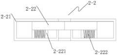
夹紧机构2-2包括夹紧壳2-21、若干组夹紧板2-22,夹紧壳2-21通过螺丝固定在套壳2上,夹紧壳2-21中滑动安装有若干组夹紧板2-22;The clamping mechanism 2-2 includes a clamping shell 2-21 and several groups of clamping plates 2-22. The clamping shell 2-21 is fixed on the
夹紧壳2-21上加工有若干组气槽,气槽为夹紧板2-22收缩到夹紧壳2-21内提供动力,夹紧壳2-21在若干组所述气槽的一端加工有弧形气槽,通过弧形气槽将所有的气槽一端导通,弧形气槽方便空气压缩器2-13将其内部的空气注入到气槽中,夹紧壳2-21上加工有三组气孔,其中两组气孔为进气孔,进气孔为空气注入提供通道,一组气孔为出气孔,出气孔为气体的释放提供通道,夹紧壳2-21在进气孔的进气端安装有单向阀,单向阀使空气只能流入不能流出,夹紧壳2-21在出气孔的出气端安装有电控阀,电控阀与控制器3-1通过导线进行电性连接,电控阀通过控制器3-1的控制将气槽中的空气释放出去,若干组夹紧板2-22的下端面焊接有气动板2-221,气动板2-221位于气槽内,气动板与气槽之间安装有夹紧弹簧2-222,若干组所述夹紧板2-22通过气动板2-221与气槽实现在夹紧壳2-21内滑动,夹紧板2-22在气槽内空气释放后通过夹紧弹簧2-222的弹性势能,将伸出夹紧壳2-21并对输液器进行流速控制。Several groups of air grooves are processed on the clamping shell 2-21, and the air grooves provide power for the clamping plate 2-22 to shrink into the clamping shell 2-21, and the clamping shell 2-21 is at one end of several groups of the air grooves. Arc-shaped air grooves are processed, and one end of all air grooves is connected through the arc-shaped air grooves. The arc-shaped air grooves are convenient for the air compressor 2-13 to inject the internal air into the air grooves, and the clamping shell 2-21 is on the There are three groups of air holes machined, of which two groups of air holes are air inlet holes, which provide channels for air injection, and one group of air holes are air holes, which provide channels for gas release. A one-way valve is installed at the intake end, and the one-way valve allows the air to flow in but not flow out. The clamping shell 2-21 is equipped with an electric control valve at the air outlet end of the air outlet, and the electric control valve and the controller 3-1 are connected by wires. Electrically connected, the electric control valve releases the air in the air tank through the control of the controller 3-1, and the pneumatic plate 2-221 is welded on the lower end surface of several groups of clamping plates 2-22, and the pneumatic plate 2-221 is located in the air In the groove, a clamping spring 2-222 is installed between the pneumatic plate and the air groove, and several groups of the clamping plates 2-22 slide in the clamping shell 2-21 through the pneumatic plate 2-221 and the air groove. After the air in the air groove is released, the clamping plate 2-22 will extend out of the clamping shell 2-21 and control the flow rate of the infusion set through the elastic potential energy of the clamping spring 2-222.
控制系统3包括控制器3-1、图像采集器3-2、无线收发器3-3,图像采集器3-2通过螺丝安装在套壳2的夹持空间中,控制器3-1中的分控制器3-12以及无线收发器3-3通过螺丝安装在套壳2的夹紧空间内,控制器3-1分别与图像采集器3-2、无线收发器3-3电性连接,图像采集器3-2对输液瓶中的药液位置进行图像采集,控制器3-1对图像进行数据处理;夹紧壳2-21与空气压缩器2-13的出气口固定,控制器3-1对夹紧壳2-21中的空气量进行控制。The
控制器3-1包括总控制器3-11和分控制器3-12,分控制器3-12设置在套壳2中,总控制器3-11设置在医院的输液室内,图像采集器3-2对输液瓶中药液的位置进行图像采集,并将采集的图像传送到分控制器3-12中,分控制器3-12对图像进行数据计算,可以算出输液速度,并根据药液的位置以及输液速度计算出药液输完的时间,分控制器3-12通过无线收发器3-3将药液输完的时间传输到总控制器3-11中,总控制器3-11根据每个分控制器3-12传输的时间,进行时间排序并建立一个时间集合T={t1、t2、t3、…tn},总控制器3-11通过无线收发器3-3将时间排序发送到医护人员的移动设备中,医护人员根据时间排序对相应的病人进行处理。The controller 3-1 includes a main controller 3-11 and a sub-controller 3-12, the sub-controller 3-12 is arranged in the
总控制器3-11通过无线收发器3-3与医护人员的移动设备连接,并获取医护人员的所在位置,根据医护人员距离需要处理的病人之间的距离,以及医护人员的移动速度,计算得到一个新的时间集合T1={a1、a2、a3、…an},此时间集合T1 为医护人员到需要处理的病人之间的时间集合,总控制器3-11将集合T和集合T1中元素向对应的时间进行相加,得到另外一个全新的时间集合T2={P1、P2、P3、…Pn},其中Pn=tn+an,此时间集合T2为医护人员对所需处理病人的总的时间集合,总控制器3-11对下一个需要处理的病人的等待时间进行公式计算,并通过无线收发器3-3将等待时间传输到相应的支架1中的分控制器3-12内。The main controller 3-11 is connected with the mobile device of the medical staff through the wireless transceiver 3-3, and obtains the location of the medical staff, and calculates the distance between the medical staff and the patient to be treated and the moving speed of the medical staff according to the distance between the medical staff and the patient to be treated. A new time set T1 ={ a1 , a2 , a3 ,...an } is obtained. This time set T1 is the time set between the medical staff and the patients who need to be treated. The overall controller 3-11 will The elements in the set T and the set T1 are added to the corresponding time to obtain another new time set T2 ={P1 , P2 , P3 ,...Pn }, where Pn =tn +an , This time setT2 is the total time set for the medical staff to treat the patient, the general controller 3-11 formulates the waiting time of the next patient to be treated, and sends the waiting time through the wireless transceiver 3-3. The time is transmitted to the sub-controllers 3-12 in the
分控制器3-12根据等待时间对输液器的流速进行控制,使输液瓶中的药液进行缓慢流淌,使得病人可以等到医护人员的处理,其中总控制器3-11对等待时间的计算公式为
本发明的工作原理:The working principle of the present invention:
套壳2上对称加工有两组滑槽2-3,两组滑槽2-3一端向下倾斜60°,伸缩杆2-12安转在滑槽2-3内,伸缩杆2-12中的连接杆2-124与夹持板2-11固定,伸缩杆2-12中的伸缩壳2-123、丝杆2-122、滑杆2-121均位于滑槽2-3内部,滑杆2-121贯穿滑槽2-3并通过滑柱与空气压缩器2-13滑动连接,丝杆2-122在与齿轮条2-31相对应的位置安装有齿轮2-14,齿轮2-14与齿轮条2-31进行齿轮传动,连接杆2-124一开始在弹簧2-125在作用下伸处伸缩壳2-123,使两组夹持板2-11之间形成的夹持空间比较小,方便对小规格尺寸的输液瓶进行夹持,当放入大规格尺寸的输液瓶时,连接杆2-124在夹持板2-11的作用下往伸缩壳2-123内收缩,以此方便对大规格尺寸的输液瓶进行夹持,当输液瓶放在承载板2-111上,由于承载板2-111为扇形结构,且承载板2-111呈坡体结构,承载板2-111的向下倾斜的坡度为10°,而且承载板2-111上通过螺丝固定有滑轮条2-112,所以导致输液瓶放置在承载板2-111上时,输液瓶在坡度为10°的坡体以及滑轮条2-112的作用下倾斜向下滑动,并在滑动的同时为承载板2-111提供向下运动的动力,承载板2-111将输液瓶上的重力通过夹持板2-11传递到伸缩杆2-12上,使得伸缩杆2-12可以在滑槽2-3内向下滑动。Two sets of chute 2-3 are symmetrically processed on the
伸缩杆2-12在滑槽2-3内向下滑动时,齿轮2-14与齿轮条2-31进行齿轮传动,丝杆2-122将在齿轮2-14的转动下与伸缩壳2-123进行丝杆传动,随着齿轮2-14的不断往下,伸缩壳2-123将不断伸出滑槽2-3,并最终与夹持板2-11接触,并阻止夹持板2-11继续往外运动。When the telescopic rod 2-12 slides down in the chute 2-3, the gear 2-14 and the gear rack 2-31 are geared, and the screw 2-122 will connect with the telescopic shell 2-123 under the rotation of the gear 2-14. Carry out the screw drive, with the continuous downward movement of the gear 2-14, the telescopic shell 2-123 will continue to extend out of the chute 2-3, and finally contact with the clamping plate 2-11, and prevent the clamping plate 2-11 Continue to move out.
两组夹持板2-11一开始在连接杆2-124的作用下形成一个较小的夹持空间,当大规格尺寸的输液瓶放入夹持空间内时,两组夹持板2-11在输液瓶的支撑下往外运动,使得连接杆2-124往伸缩壳2-123内运动,当夹持板2-11将输液瓶的重力传递到伸缩杆2-12上时,伸缩杆2-12将在滑槽2-3内向下运动,两组夹持板2-11也将在伸缩杆2-12往下运动的同时向中间靠拢,并与套壳2相互配合形成一个完整的圆形夹持空间,随着夹持板2-11的不断下降,丝杆2-122将在齿轮2-14的带动下与伸缩壳2-123进行丝杆传动,并将伸缩壳2-123传动出滑槽2-3,使伸缩壳2-123的右端抵在伸缩壳2-123上,对夹持板2-11进行位置固定,使得两组夹持板2-11可以形成相对稳定的夹持空间。The two sets of clamping plates 2-11 initially form a small clamping space under the action of the connecting rod 2-124. When a large-sized infusion bottle is placed in the clamping space, the two sets of clamping plates 2- 11 Move outward under the support of the infusion bottle, so that the connecting rod 2-124 moves into the telescopic shell 2-123. When the clamping plate 2-11 transmits the gravity of the infusion bottle to the telescopic rod 2-12, the telescopic rod 2 -12 will move downward in the chute 2-3, and the two sets of clamping plates 2-11 will also move toward the middle when the telescopic rod 2-12 moves downward, and cooperate with the
伸缩杆2-12向下运动时,通过滑杆2-121对空气压缩器2-13进行空气压缩,使得空气压缩器2-13中的空气通过进气孔进入气槽内,使得夹紧板2-22在空气的推动下向夹紧壳2-21内收缩,使得输液器可以处于夹紧壳2-21的中间位置,当分控制器3-12需要控制药液流速时,分控制器3-12将控制电控阀释放空气,由于气槽内空气的释放,夹紧板2-22将在夹紧弹簧2-222的弹性势能的作用下伸出夹紧壳2-21并对输液器进行夹紧,使得输液器的流通通过发生变化,从而达到对输液速度的控制。When the telescopic rod 2-12 moves downward, the air compressor 2-13 is compressed by the sliding rod 2-121, so that the air in the air compressor 2-13 enters the air groove through the air inlet hole, so that the clamping plate 2-22 is pushed into the clamping shell 2-21 by the air, so that the infusion set can be in the middle position of the clamping shell 2-21. When the sub-controller 3-12 needs to control the flow rate of the liquid medicine, the sub-controller 3 -12 will control the electric control valve to release the air, due to the release of the air in the air groove, the clamping plate 2-22 will protrude out of the clamping shell 2-21 under the action of the elastic potential energy of the clamping spring 2-222 and align the infusion set Clamping is performed to change the circulation of the infusion set, so as to control the infusion speed.
控制系统3包括控制器3-1、图像采集器3-2、无线收发器3-3,图像采集器3-2通过螺丝安装在套壳2的夹持空间中,控制器3-1中的分控制器3-12以及无线收发器3-3通过螺丝安装在套壳2的夹紧空间内,控制器3-1分别与图像采集器3-2、无线收发器3-3电性连接,图像采集器3-2对输液瓶中的药液位置进行图像采集,控制器3-1对图像进行数据处理。The
控制器3-1包括总控制器3-11和分控制器3-12,分控制器3-12设置在套壳2中,总控制器3-11设置在医院的输液室内,图像采集器3-2对输液瓶中药液的位置进行图像采集,并将采集的图像传送到分控制器3-12中,分控制器3-12对图像进行数据计算,可以算出输液速度,并根据药液的位置以及输液速度计算出药液输完的时间,分控制器3-12通过无线收发器3-3将药液输完的时间传输到总控制器3-11中,总控制器3-11根据每个分控制器3-12传输的时间,进行时间排序并建立一个时间集合T={t1、t2、t3、…tn},总控制器3-11通过无线收发器3-3将时间排序发送到医护人员的移动设备中,医护人员根据时间排序对相应的病人进行处理。The controller 3-1 includes a main controller 3-11 and a sub-controller 3-12, the sub-controller 3-12 is arranged in the
总控制器3-11通过无线收发器3-3与医护人员的移动设备连接,并获取医护人员的所在位置,根据医护人员距离需要处理的病人之间的距离,以及医护人员的移动速度,计算得到一个新的时间集合T1={a1、a2、a3、…an},此时间集合T1 为医护人员到需要处理的病人之间的时间集合,总控制器3-11将集合T和集合T1中元素向对应的时间进行相加,得到另外一个全新的时间集合T2={P1、P2、P3、…Pn},其中Pn=tn+an,此时间集合T2为医护人员对所需处理病人的总的时间集合,总控制器3-11对下一个需要处理的病人的等待时间进行公式计算,并通过无线收发器3-3将等待时间传输到相应的支架1中的分控制器3-12内。The main controller 3-11 is connected with the mobile device of the medical staff through the wireless transceiver 3-3, and obtains the location of the medical staff, and calculates the distance between the medical staff and the patient to be treated and the moving speed of the medical staff according to the distance between the medical staff and the patient to be treated. A new time set T1 ={ a1 , a2 , a3 ,...an } is obtained. This time set T1 is the time set between the medical staff and the patients who need to be treated. The overall controller 3-11 will The elements in the set T and the set T1 are added to the corresponding time to obtain another new time set T2 ={P1 , P2 , P3 ,...Pn }, where Pn =tn +an , This time set T2 is the total time set for the medical staff to treat the patient.The general controller 3-11 formulates the waiting time of the next patient to be treated, and sends the waiting time through the wireless transceiver 3-3. The time is transmitted to the sub-controllers 3-12 in the
分控制器3-12根据等待时间对输液器的流速进行控制,使输液瓶中的药液进行缓慢流淌,使得病人可以等到医护人员的处理,其中总控制器3-11对等待时间的计算公式为
对于本领域技术人员而言,显然本发明不限于上述示范性实施例的细节,而且在不背离本发明的精神或基本特征的情况下,能够以其他的具体形式实现本发明。因此,无论从哪一点来看,均应将实施例看作是示范性的,而且是非限制性的,本发明的范围由所附权利要求而不是上述说明限定,因此旨在将落在权利要求的等同要件的含义和范围内的所有变化囊括在本发明内。不应将权利要求中的任何附图标记视为限制所涉及的权利要求。It will be apparent to those skilled in the art that the present invention is not limited to the details of the above-described exemplary embodiments, but that the present invention may be embodied in other specific forms without departing from the spirit or essential characteristics of the invention. Therefore, the embodiments are to be regarded in all respects as illustrative and not restrictive, and the scope of the invention is to be defined by the appended claims rather than the foregoing description, which are therefore intended to fall within the scope of the claims. All changes within the meaning and scope of the equivalents of , are included in the present invention. Any reference signs in the claims shall not be construed as limiting the involved claim.
Claims (9)

Priority Applications (3)
| Application Number | Priority Date | Filing Date | Title |
|---|---|---|---|
| CN202110083999.0ACN112891677B (en) | 2020-03-18 | 2020-03-18 | Medical liquid level off-limit alarm device |
| CN202010193276.1ACN111282087B (en) | 2020-03-18 | 2020-03-18 | A medical liquid level over-limit alarm device |
| CN202110082290.9ACN112891676B (en) | 2020-03-18 | 2020-03-18 | Medical liquid level over limit alarm device |
Applications Claiming Priority (1)
| Application Number | Priority Date | Filing Date | Title |
|---|---|---|---|
| CN202010193276.1ACN111282087B (en) | 2020-03-18 | 2020-03-18 | A medical liquid level over-limit alarm device |
Related Child Applications (2)
| Application Number | Title | Priority Date | Filing Date |
|---|---|---|---|
| CN202110082290.9ADivisionCN112891676B (en) | 2020-03-18 | 2020-03-18 | Medical liquid level over limit alarm device |
| CN202110083999.0ADivisionCN112891677B (en) | 2020-03-18 | 2020-03-18 | Medical liquid level off-limit alarm device |
Publications (2)
| Publication Number | Publication Date |
|---|---|
| CN111282087Atrue CN111282087A (en) | 2020-06-16 |
| CN111282087B CN111282087B (en) | 2021-02-19 |
Family
ID=71030319
Family Applications (3)
| Application Number | Title | Priority Date | Filing Date |
|---|---|---|---|
| CN202110082290.9AWithdrawn - After IssueCN112891676B (en) | 2020-03-18 | 2020-03-18 | Medical liquid level over limit alarm device |
| CN202010193276.1AActiveCN111282087B (en) | 2020-03-18 | 2020-03-18 | A medical liquid level over-limit alarm device |
| CN202110083999.0AActiveCN112891677B (en) | 2020-03-18 | 2020-03-18 | Medical liquid level off-limit alarm device |
Family Applications Before (1)
| Application Number | Title | Priority Date | Filing Date |
|---|---|---|---|
| CN202110082290.9AWithdrawn - After IssueCN112891676B (en) | 2020-03-18 | 2020-03-18 | Medical liquid level over limit alarm device |
Family Applications After (1)
| Application Number | Title | Priority Date | Filing Date |
|---|---|---|---|
| CN202110083999.0AActiveCN112891677B (en) | 2020-03-18 | 2020-03-18 | Medical liquid level off-limit alarm device |
Country Status (1)
| Country | Link |
|---|---|
| CN (3) | CN112891676B (en) |
Cited By (2)
| Publication number | Priority date | Publication date | Assignee | Title |
|---|---|---|---|---|
| CN112354038A (en)* | 2020-10-27 | 2021-02-12 | 陈玲燕 | Infusion bottle support capable of prompting to change medicine |
| CN112741771A (en)* | 2021-02-05 | 2021-05-04 | 西昌市人民医院 | Medicine feeding device convenient for pediatric nursing |
Families Citing this family (3)
| Publication number | Priority date | Publication date | Assignee | Title |
|---|---|---|---|---|
| CN113587078B (en)* | 2021-08-03 | 2023-04-07 | 李武鹏 | Boiler liquid level detection device |
| CN114129361B (en)* | 2021-12-09 | 2023-06-30 | 南京市蓝业科技有限公司 | Pediatric nursing drip injection bed |
| CN115837105B (en)* | 2023-02-27 | 2023-05-02 | 华序科技开发(深圳)有限公司 | Infusion prompting method and system for intelligent ward |
Citations (8)
| Publication number | Priority date | Publication date | Assignee | Title |
|---|---|---|---|---|
| US20050095063A1 (en)* | 2003-10-30 | 2005-05-05 | Fathallah Marwan A. | Medical device system |
| CN106421962A (en)* | 2016-08-27 | 2017-02-22 | 钟国平 | Multifunctional infusion bottle hanging device for medical use |
| CN106964015A (en)* | 2017-02-28 | 2017-07-21 | 成都迅德科技有限公司 | A kind of Medical infusion hook device |
| CN206391299U (en)* | 2016-09-28 | 2017-08-11 | 安徽工程大学机电学院 | A kind of infusion alarm |
| CN207286407U (en)* | 2017-03-03 | 2018-05-01 | 新疆医科大学第一附属医院 | A kind of infusion alarm of the medical call of wireless connection |
| US10010686B2 (en)* | 2006-02-27 | 2018-07-03 | Ivenix, Inc. | Fluid control system and disposable assembly |
| CN109568713A (en)* | 2018-11-30 | 2019-04-05 | 中国人民解放军陆军军医大学第附属医院 | Run-resistant infusion device |
| CN208958982U (en)* | 2018-07-20 | 2019-06-11 | 深圳市宝安区沙井人民医院 | A kind of medical Transfusion device warning device |
- 2020
- 2020-03-18CNCN202110082290.9Apatent/CN112891676B/ennot_activeWithdrawn - After Issue
- 2020-03-18CNCN202010193276.1Apatent/CN111282087B/enactiveActive
- 2020-03-18CNCN202110083999.0Apatent/CN112891677B/enactiveActive
Patent Citations (8)
| Publication number | Priority date | Publication date | Assignee | Title |
|---|---|---|---|---|
| US20050095063A1 (en)* | 2003-10-30 | 2005-05-05 | Fathallah Marwan A. | Medical device system |
| US10010686B2 (en)* | 2006-02-27 | 2018-07-03 | Ivenix, Inc. | Fluid control system and disposable assembly |
| CN106421962A (en)* | 2016-08-27 | 2017-02-22 | 钟国平 | Multifunctional infusion bottle hanging device for medical use |
| CN206391299U (en)* | 2016-09-28 | 2017-08-11 | 安徽工程大学机电学院 | A kind of infusion alarm |
| CN106964015A (en)* | 2017-02-28 | 2017-07-21 | 成都迅德科技有限公司 | A kind of Medical infusion hook device |
| CN207286407U (en)* | 2017-03-03 | 2018-05-01 | 新疆医科大学第一附属医院 | A kind of infusion alarm of the medical call of wireless connection |
| CN208958982U (en)* | 2018-07-20 | 2019-06-11 | 深圳市宝安区沙井人民医院 | A kind of medical Transfusion device warning device |
| CN109568713A (en)* | 2018-11-30 | 2019-04-05 | 中国人民解放军陆军军医大学第附属医院 | Run-resistant infusion device |
Cited By (2)
| Publication number | Priority date | Publication date | Assignee | Title |
|---|---|---|---|---|
| CN112354038A (en)* | 2020-10-27 | 2021-02-12 | 陈玲燕 | Infusion bottle support capable of prompting to change medicine |
| CN112741771A (en)* | 2021-02-05 | 2021-05-04 | 西昌市人民医院 | Medicine feeding device convenient for pediatric nursing |
Also Published As
| Publication number | Publication date |
|---|---|
| CN111282087B (en) | 2021-02-19 |
| CN112891676A (en) | 2021-06-04 |
| CN112891677B (en) | 2022-12-06 |
| CN112891676B (en) | 2022-12-06 |
| CN112891677A (en) | 2021-06-04 |
Similar Documents
| Publication | Publication Date | Title |
|---|---|---|
| CN111282087A (en) | Medical liquid level off-limit alarm device | |
| CN105833383B (en) | A kind of automatic infusion robot | |
| CN109350794A (en) | A kind of internal medicine Medical stand for transfusion | |
| CN106075632A (en) | Medical Intelligent Robot Based on Internet of Things | |
| CN118236584A (en) | Intelligent automatic medicine changing infusion support | |
| CN213191696U (en) | A ward infusion support for department of neurology | |
| CN207979922U (en) | A kind of nursing chlorination equipment | |
| CN215504819U (en) | Gravity venous transfusion nursing management device | |
| CN215460850U (en) | A kind of intravenous infusion nursing management device | |
| CN221981289U (en) | A heatable infusion device | |
| CN218129089U (en) | Medicine placing plate | |
| CN202802337U (en) | Infusion support special for nutrition and food hygiene | |
| CN211611053U (en) | Infusion auxiliary stand is used in nursing | |
| CN222110633U (en) | A passive infusion pump | |
| CN216022448U (en) | Nursing infusion auxiliary stand | |
| CN217793965U (en) | Movable infusion device suitable for micro pump | |
| CN215274989U (en) | Infusion support for general nursing | |
| CN214911808U (en) | Infusion alarm with drop number display function | |
| CN209048781U (en) | A kind of Micropump bracket | |
| CN215460772U (en) | Enema bag of accurate regulation and control | |
| CN215426523U (en) | Nursing branch of academic or vocational study is with infusion auxiliary stand | |
| CN221600858U (en) | Portable transfusion support | |
| CN216366108U (en) | Surgical suction device with adjustable flow | |
| CN214050006U (en) | An easy-to-install infusion stand for nursing professions | |
| CN216777656U (en) | Portable movable infusion support |
Legal Events
| Date | Code | Title | Description |
|---|---|---|---|
| PB01 | Publication | ||
| PB01 | Publication | ||
| SE01 | Entry into force of request for substantive examination | ||
| SE01 | Entry into force of request for substantive examination | ||
| TA01 | Transfer of patent application right | ||
| TA01 | Transfer of patent application right | Effective date of registration:20210129 Address after:325600 No.192, niubidong village, Yueqing City, Wenzhou City, Zhejiang Province Applicant after:Qian Caiying Address before:210000 No.8 Jiangcheng Avenue, Qixia District, Nanjing City, Jiangsu Province Applicant before:Zhao Peng | |
| GR01 | Patent grant | ||
| GR01 | Patent grant | ||
| TR01 | Transfer of patent right | ||
| TR01 | Transfer of patent right | Effective date of registration:20250424 Address after:Unit 2212, Building 1, I Duhui Community, No. 11 Tangyan South Road, High tech Zone, Xi'an City, Shaanxi Province 710000 Patentee after:Chuanghe Zhizao (Xi'an) Technology Co.,Ltd. Country or region after:China Address before:325600 No.192, niubidong village, Yueqing City, Wenzhou City, Zhejiang Province Patentee before:Qian Caiying Country or region before:China |