CN111281530A - Breast conserving surgery gland flap fixation knife - Google Patents
Breast conserving surgery gland flap fixation knifeDownload PDFInfo
- Publication number
- CN111281530A CN111281530ACN202010229327.1ACN202010229327ACN111281530ACN 111281530 ACN111281530 ACN 111281530ACN 202010229327 ACN202010229327 ACN 202010229327ACN 111281530 ACN111281530 ACN 111281530A
- Authority
- CN
- China
- Prior art keywords
- breast
- opening
- annular blade
- driving device
- handle
- Prior art date
- Legal status (The legal status is an assumption and is not a legal conclusion. Google has not performed a legal analysis and makes no representation as to the accuracy of the status listed.)
- Pending
Links
- 210000004907glandAnatomy0.000titleclaimsabstractdescription8
- 238000001356surgical procedureMethods0.000titleabstractdescription18
- 210000000481breastAnatomy0.000title1
- 230000000762glandularEffects0.000claimsdescription11
- 238000003825pressingMethods0.000claimsdescription2
- 238000005520cutting processMethods0.000abstractdescription20
- 206010028980NeoplasmDiseases0.000abstractdescription8
- 230000000694effectsEffects0.000abstractdescription7
- 230000007480spreadingEffects0.000abstractdescription2
- 238000000034methodMethods0.000description5
- 206010006187Breast cancerDiseases0.000description2
- 208000026310Breast neoplasmDiseases0.000description2
- 238000005345coagulationMethods0.000description2
- 230000015271coagulationEffects0.000description2
- 230000008569processEffects0.000description2
- 238000010586diagramMethods0.000description1
- 230000023597hemostasisEffects0.000description1
- 238000009413insulationMethods0.000description1
- 230000002980postoperative effectEffects0.000description1
- 238000002271resectionMethods0.000description1
- 238000000926separation methodMethods0.000description1
- 230000009466transformationEffects0.000description1
- 238000000844transformationMethods0.000description1
Images


Classifications
- A—HUMAN NECESSITIES
- A61—MEDICAL OR VETERINARY SCIENCE; HYGIENE
- A61B—DIAGNOSIS; SURGERY; IDENTIFICATION
- A61B18/00—Surgical instruments, devices or methods for transferring non-mechanical forms of energy to or from the body
- A61B18/04—Surgical instruments, devices or methods for transferring non-mechanical forms of energy to or from the body by heating
- A61B18/12—Surgical instruments, devices or methods for transferring non-mechanical forms of energy to or from the body by heating by passing a current through the tissue to be heated, e.g. high-frequency current
- A61B18/14—Probes or electrodes therefor
- A—HUMAN NECESSITIES
- A61—MEDICAL OR VETERINARY SCIENCE; HYGIENE
- A61B—DIAGNOSIS; SURGERY; IDENTIFICATION
- A61B18/00—Surgical instruments, devices or methods for transferring non-mechanical forms of energy to or from the body
- A61B2018/00315—Surgical instruments, devices or methods for transferring non-mechanical forms of energy to or from the body for treatment of particular body parts
- A61B2018/00333—Breast
- A—HUMAN NECESSITIES
- A61—MEDICAL OR VETERINARY SCIENCE; HYGIENE
- A61B—DIAGNOSIS; SURGERY; IDENTIFICATION
- A61B18/00—Surgical instruments, devices or methods for transferring non-mechanical forms of energy to or from the body
- A61B2018/00571—Surgical instruments, devices or methods for transferring non-mechanical forms of energy to or from the body for achieving a particular surgical effect
- A61B2018/00607—Coagulation and cutting with the same instrument
- A—HUMAN NECESSITIES
- A61—MEDICAL OR VETERINARY SCIENCE; HYGIENE
- A61B—DIAGNOSIS; SURGERY; IDENTIFICATION
- A61B18/00—Surgical instruments, devices or methods for transferring non-mechanical forms of energy to or from the body
- A61B2018/0091—Handpieces of the surgical instrument or device
- A61B2018/00916—Handpieces of the surgical instrument or device with means for switching or controlling the main function of the instrument or device
- A—HUMAN NECESSITIES
- A61—MEDICAL OR VETERINARY SCIENCE; HYGIENE
- A61B—DIAGNOSIS; SURGERY; IDENTIFICATION
- A61B18/00—Surgical instruments, devices or methods for transferring non-mechanical forms of energy to or from the body
- A61B18/04—Surgical instruments, devices or methods for transferring non-mechanical forms of energy to or from the body by heating
- A61B18/12—Surgical instruments, devices or methods for transferring non-mechanical forms of energy to or from the body by heating by passing a current through the tissue to be heated, e.g. high-frequency current
- A61B18/14—Probes or electrodes therefor
- A61B2018/1405—Electrodes having a specific shape
- A61B2018/1407—Loop
Landscapes
- Health & Medical Sciences (AREA)
- Surgery (AREA)
- Engineering & Computer Science (AREA)
- Life Sciences & Earth Sciences (AREA)
- Biomedical Technology (AREA)
- Otolaryngology (AREA)
- Nuclear Medicine, Radiotherapy & Molecular Imaging (AREA)
- Plasma & Fusion (AREA)
- Physics & Mathematics (AREA)
- Heart & Thoracic Surgery (AREA)
- Medical Informatics (AREA)
- Molecular Biology (AREA)
- Animal Behavior & Ethology (AREA)
- General Health & Medical Sciences (AREA)
- Public Health (AREA)
- Veterinary Medicine (AREA)
- Surgical Instruments (AREA)
Abstract
Translated fromChinese
Description
Translated fromChinese技术领域technical field
本发明涉及手术刀技术领域,具体涉及一种保乳手术腺瓣固定刀。The invention relates to the technical field of surgical knives, in particular to a gland flap fixing knife for breast-conserving surgery.
背景技术Background technique
保乳手术及术后综合治疗已成为治疗早期乳腺癌的主要方法之一,对于保乳手术,采用手术固定刀进行切除,可以达到较好的手术效果,手术固定刀是一种取代机械手术刀进行组织切割的电外科器械。它通过有效电极尖端产生的高频高压电流与肌体接触时对组织进行加热,实现对肌体组织的分离和凝固,从而起到切割和止血的目的,目前的手术固定刀在进行保乳手术时,需要弧形切口或是放射状切口,由于乳腺肿瘤组织的活动性大,难以固定,目前的切割方式会导致切割效果达不到要求,造成切割残留从而导致手术效果较差。Breast-conserving surgery and postoperative comprehensive treatment have become one of the main methods for the treatment of early breast cancer. For breast-conserving surgery, a fixed surgical knife can be used for resection, which can achieve better surgical results. Electrosurgical instruments for tissue cutting. It heats the tissue when it is in contact with the body through the high-frequency high-voltage current generated by the effective electrode tip to achieve separation and coagulation of the body tissue, thereby achieving the purpose of cutting and hemostasis. An arc-shaped incision or radial incision is required. Due to the large mobility of breast tumor tissue, it is difficult to fix it. The current cutting method will lead to the incision effect not meeting the requirements, resulting in residual incision and poor surgical effect.
发明内容SUMMARY OF THE INVENTION
本发明旨在至少在一定程度上解决相关技术中的技术问题之一。为此,本发明的一个目的在于提出一种保乳手术腺瓣固定刀,包括:The present invention aims to solve one of the technical problems in the related art at least to a certain extent. For this reason, an object of the present invention is to propose a breast-conserving surgery gland flap fixation knife, comprising:
手柄,所述手柄的一端设置有固定部,且所述手柄内设置有驱动装置;a handle, one end of the handle is provided with a fixing part, and a driving device is provided in the handle;
撑开组件,所述撑开组件的一端贯穿所述固定部与所述驱动装置相连接,另一端延伸至所述手柄外;a spreader assembly, one end of the spreader assembly is connected to the driving device through the fixing part, and the other end extends outside the handle;
环形刀片,所述环形刀片间隔设置且与所述撑开组件的另一端相连接,其中,所述驱动装置用于驱动所述撑开组件,以迫使所述撑开组件带动所述环形刀片径向张开或合拢。an annular blade, the annular blade is spaced apart and connected with the other end of the expansion assembly, wherein the driving device is used to drive the expansion assembly to force the expansion assembly to drive the annular blade diameter to open or close.
优选地,根据本发明的一个实施例,所述撑开组件包括:Preferably, according to an embodiment of the present invention, the expansion assembly includes:
推杆,所述推杆的一端连接于所述驱动装置;a push rod, one end of the push rod is connected to the drive device;
张合件,所述张合件的顶部枢转连接于所述推杆的另一端,且底部枢转连接于所述环形刀片;A tensioning member, the top of the tensioning member is pivotally connected to the other end of the push rod, and the bottom is pivotally connected to the annular blade;
限位杆,所述限位杆为可伸缩结构,且所述限位杆顶部枢转连接于所述固定部,底部滑动连接于所述张合件外侧;a limit rod, the limit rod is a retractable structure, and the top of the limit rod is pivotally connected to the fixing part, and the bottom is slidably connected to the outside of the tension member;
其中,所述推杆用于带动所述张合件,以迫使所述张合件与所述环形刀片共同张开或合拢。Wherein, the push rod is used to drive the tensioning member, so as to force the tensioning member and the annular blade to open or close together.
优选地,根据本发明的一个实施例,所述限位杆底部形成为球形且嵌入所述张合件外侧,并位于所述张合件下端,以使所述限位杆限制所述张合件的运动方向。Preferably, according to an embodiment of the present invention, the bottom of the limiting rod is formed into a spherical shape and is embedded in the outer side of the tensioning member, and is located at the lower end of the tensioning member, so that the limiting rod restricts the tensioning direction of movement of the piece.
优选地,根据本发明的一个实施例,所述驱动装置为直线电机,所述直线电机具有定子和动子,所述定子固定于所述手柄内,所述动子与所述推杆相连接。Preferably, according to an embodiment of the present invention, the driving device is a linear motor, the linear motor has a stator and a mover, the stator is fixed in the handle, and the mover is connected to the push rod .
优选地,根据本发明的一个实施例,所述环形刀片顶部设置有用于将所述环形刀片顶部绝缘的绝缘部,所述张合件密封于所述绝缘部内与所述环形刀片相连接。Preferably, according to an embodiment of the present invention, an insulating portion for insulating the top of the annular blade is provided on the top of the annular blade, and the tensioning member is sealed in the insulating portion and connected to the annular blade.
优选地,根据本发明的一个实施例,所述环形刀片为至少三个弧形刀片组成,且每个所述弧形刀片均分隔设置;Preferably, according to an embodiment of the present invention, the annular blade is composed of at least three arc-shaped blades, and each of the arc-shaped blades is arranged separately;
其中,所述张合件至少具有三个且分别与每个所述弧形刀片相连接,以分别带动每个所述弧形刀片相互远离或靠近。Wherein, the tension members have at least three and are respectively connected to each of the arc-shaped blades, so as to drive each of the arc-shaped blades to move away from or approach each other.
优选地,根据本发明的一个实施例,还包括电源线,所述电源线连接于所述手柄,且相对于所述环形刀片的另一端,用于连接至主机以提供供电。Preferably, according to an embodiment of the present invention, a power cord is further included, the power cord is connected to the handle, and opposite to the other end of the annular blade, for connecting to a host for supplying power.
优选地,根据本发明的一个实施例,还包括电路板,所述电路板分别与所述电源线及所述驱动装置相连接,用于控制并向所述驱动装置供电。Preferably, according to an embodiment of the present invention, a circuit board is further included, the circuit board is respectively connected with the power line and the driving device, and is used for controlling and supplying power to the driving device.
优选地,根据本发明的一个实施例,所述手柄上还设置有按键,所述按键与所述电路板具有的控制按键相抵贴,用于按压所述控制按键以使所述电路板控制所述驱动装置。Preferably, according to an embodiment of the present invention, a button is further provided on the handle, and the button is abutted against a control button of the circuit board, and is used to press the control button to make the circuit board control the control button. the drive device.
本发明提供的保乳手术腺瓣固定刀,可以在医护人员使用时用手抓持手柄,然后控制驱动装置,使得驱动装置驱动撑开组件并带动环形刀片张开或合拢,针对不同的肿瘤组织可以将环形刀片进行调节至不同的径向尺寸,从而抵贴至肿瘤组织上进行固定并进行切割,使得在保乳手术中的肿瘤组织固定更稳定,切割效果更好且避免了造成切割残留,使得手术效果更好。The gland flap fixing knife for breast-conserving surgery provided by the present invention can be used by medical staff to hold the handle by hand, and then control the driving device, so that the driving device drives the opening assembly and drives the annular blade to open or close, aiming at different tumor tissues. The annular blade can be adjusted to different radial sizes, so as to stick to the tumor tissue for fixation and cutting, which makes the tumor tissue fixation in breast-conserving surgery more stable, the cutting effect is better, and the cutting residue is avoided. make the surgery better.
本发明的附加方面和优点将在下面的描述中部分给出,部分将从下面的描述中变得明显,或通过本发明的实践了解到。Additional aspects and advantages of the present invention will be set forth, in part, from the following description, and in part will be apparent from the following description, or may be learned by practice of the invention.
附图说明Description of drawings
为了更清楚地说明本发明实施例或现有技术中的技术方案,下面将对实施例或现有技术描述中所需要使用的附图作简单地介绍,显而易见地,下面描述中的附图仅仅是本发明的一些实施例,对于本领域普通技术人员来讲,在不付出创造性劳动的前提下,还可以根据这些附图示出的结构获得其他的附图。In order to explain the embodiments of the present invention or the technical solutions in the prior art more clearly, the following briefly introduces the accompanying drawings that need to be used in the description of the embodiments or the prior art. Obviously, the accompanying drawings in the following description are only These are some embodiments of the present invention, and for those of ordinary skill in the art, other drawings can also be obtained according to the structures shown in these drawings without creative efforts.
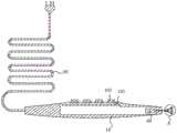
图1是本发明实施例中提供的保乳手术腺瓣固定刀的结构示意图;Fig. 1 is the structural representation of the breast-conserving surgery glandular flap fixing knife provided in the embodiment of the present invention;
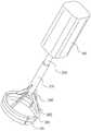
图2是本发明实施例中提供的保乳手术腺瓣固定刀的剖视图;2 is a cross-sectional view of a breast-conserving surgery glandular flap fixing knife provided in an embodiment of the present invention;
图3是图2所示的A部放大图;Fig. 3 is the enlarged view of A part shown in Fig. 2;
图4是本发明实施例中提供的驱动装置、撑开组件及环形刀片的结构示意图。FIG. 4 is a schematic structural diagram of a driving device, a spreading assembly and an annular blade provided in an embodiment of the present invention.
附图标号说明:Description of reference numbers:
10、手柄;101、固定部;102、按键;103、电路板;20、撑开组件;201、推杆;202、张合件;203、限位杆;30、环形刀片;301、绝缘部;40、驱动装置;50、电源线。10, handle; 101, fixed part; 102, button; 103, circuit board; 20, opening assembly; 201, push rod; 202, tensioning part; 203, limit rod; 30, annular blade; 301, insulating part ; 40, drive device; 50, power cord.
本发明目的的实现、功能特点及优点将结合实施例,参照附图做进一步说明。The realization, functional characteristics and advantages of the present invention will be further described with reference to the accompanying drawings in conjunction with the embodiments.
具体实施方式Detailed ways
下面详细描述本发明的实施例,所述实施例的示例在附图中示出,其中自始至终相同或类似的标号表示相同或类似的元件或具有相同或类似功能的元件。下面通过参考附图描述的实施例是示例性的,旨在用于解释本发明,而不能理解为对本发明的限制,基于本发明中的实施例,本领域普通技术人员在没有作出创造性劳动前提下所获得的所有其他实施例,都属于本发明保护的范围。The following describes in detail the embodiments of the present invention, examples of which are illustrated in the accompanying drawings, wherein the same or similar reference numerals refer to the same or similar elements or elements having the same or similar functions throughout. The embodiments described below with reference to the accompanying drawings are exemplary, and are intended to be used to explain the present invention, but should not be construed as a limitation of the present invention. Based on the embodiments of the present invention, those of ordinary skill in the art do not make any creative work premise. All other embodiments obtained below belong to the protection scope of the present invention.
在本发明的描述中,需要理解的是,术语“中心”、“纵向”、“横向”、“长度”、“宽度”、“厚度”、“上”、“下”、“前”、“后”、“左”、“右”、“竖直”、“水平”、“顶”、“底”“内”、“外”、“顺时针”、“逆时针”“轴向”、“周向”、“径向”等指示的方位或位置关系为基于附图所示的方位或位置关系,仅是为了便于描述本发明和简化描述,而不是指示或暗示所指的装置或元件必须具有特定的方位、以特定的方位构造和操作,因此不能理解为对本发明的限制。In the description of the present invention, it should be understood that the terms "center", "longitudinal", "lateral", "length", "width", "thickness", "upper", "lower", "front", " Back, Left, Right, Vertical, Horizontal, Top, Bottom, Inner, Outer, Clockwise, Counterclockwise, Axial, " The orientation or positional relationship indicated by "circumferential", "radial", etc. is based on the orientation or positional relationship shown in the drawings, and is only for the convenience of describing the present invention and simplifying the description, rather than indicating or implying that the indicated device or element must be It has a specific orientation, is constructed and operates in a specific orientation, and therefore should not be construed as a limitation of the present invention.
此外,术语“第一”、“第二”仅用于描述目的,而不能理解为指示或暗示相对重要性或者隐含指明所指示的技术特征的数量。由此,限定有“第一”、“第二”的特征可以明示或者隐含地包括一个或者更多个该特征。在本发明的描述中,“多个”的含义是两个或两个以上,除非另有明确具体的限定。In addition, the terms "first" and "second" are only used for descriptive purposes, and should not be construed as indicating or implying relative importance or implying the number of indicated technical features. Thus, a feature defined as "first" or "second" may expressly or implicitly include one or more of that feature. In the description of the present invention, "plurality" means two or more, unless otherwise expressly and specifically defined.
在本发明中,除非另有明确的规定和限定,术语“安装”、“相连”、“连接”、“固定”等术语应做广义理解,例如,可以是固定连接,也可以是可拆卸连接,或一体地连接;可以是机械连接,也可以是电连接;可以是直接相连,也可以通过中间媒介间接相连,可以是两个元件内部的连通。对于本领域的普通技术人员而言,可以根据具体情况理解上述术语在本发明中的具体含义。In the present invention, unless otherwise expressly specified and limited, the terms "installed", "connected", "connected", "fixed" and other terms should be understood in a broad sense, for example, it may be a fixed connection or a detachable connection , or integrally connected; it can be a mechanical connection or an electrical connection; it can be a direct connection, or an indirect connection through an intermediate medium, or the internal communication between the two components. For those of ordinary skill in the art, the specific meanings of the above terms in the present invention can be understood according to specific situations.
在本发明中,除非另有明确的规定和限定,第一特征在第二特征之“上”或之“下”可以包括第一和第二特征直接接触,也可以包括第一和第二特征不是直接接触而是通过它们之间的另外的特征接触。而且,第一特征在第二特征“之上”、“上方”和“上面”包括第一特征在第二特征正上方和斜上方,或仅仅表示第一特征水平高度高于第二特征。第一特征在第二特征“之下”、“下方”和“下面”包括第一特征在第二特征正下方和斜下方,或仅仅表示第一特征水平高度小于第二特征。In the present invention, unless otherwise expressly specified and limited, a first feature "on" or "under" a second feature may include the first and second features in direct contact, or may include the first and second features Not directly but through additional features between them. Also, the first feature being "above", "over" and "above" the second feature includes the first feature being directly above and obliquely above the second feature, or simply means that the first feature is level higher than the second feature. The first feature is "below", "below" and "below" the second feature includes the first feature being directly below and diagonally below the second feature, or simply means that the first feature has a lower level than the second feature.
下面参照附图详细描述本发明实施例的保乳手术腺瓣固定刀。The breast-conserving surgery gland flap fixing knife according to the embodiment of the present invention will be described in detail below with reference to the accompanying drawings.
参照图1所示,本发明提供的保乳手术腺瓣固定刀,包括手柄10、撑开组件20及环形刀片30,手柄10的一端设置有固定部101,且手柄10内设置有驱动装置40;撑开组件20的一端贯穿固定部101与驱动装置40相连接,另一端延伸至手柄10外;环形刀片30间隔设置且与撑开组件20的另一端相连接,其中,驱动装置40用于驱动撑开组件20,以迫使撑开组件20带动环形刀片30径向张开或合拢。Referring to FIG. 1 , the breast-conserving surgery glandular flap fixing knife provided by the present invention includes a
本发明提供的保乳手术腺瓣固定刀,可以在医护人员使用时用手抓持手柄10,然后控制驱动装置40,使得驱动装置40驱动撑开组件20并带动环形刀片30张开或合拢,针对不同的肿瘤组织可以将环形刀片30进行调节至不同的径向尺寸,从而抵贴至肿瘤组织上进行固定并进行切割,使得在保乳手术中的肿瘤组织固定更稳定,切割效果更好且避免了造成切割残留,使得手术效果更好。In the breast-conserving surgery glandular flap fixing knife provided by the present invention, the medical staff can hold the
具体的,撑开组件20包括推杆201、张合件202及限位杆203,推杆201的一端连接于驱动装置40;张合件202的顶部枢转连接于推杆201的另一端,且底部枢转连接于环形刀片30;限位杆203为可伸缩结构,且限位杆203顶部枢转连接于固定部101,底部滑动连接于张合件202外侧;其中,推杆201用于带动张合件202,以迫使张合件202与环形刀片30共同张开或合拢。Specifically, the
在本实施例中,在撑开组件20将环形刀片30撑开时,驱动装置40带动推杆201呈直线运动,使得推杆201伸出固定部101并推动张合件202的两端转动,当张合件202枢转至与环形刀片30平齐时,限位杆203被拉伸至最长,并且环形刀片30径向尺寸最大;在驱动装置40带动推杆201缩回固定部101时,推杆201拉动张合件202使得张合件202进行转动,张合件202合拢时带动环形刀片30共同合拢,当环形刀片30完全合拢时则径向尺寸最小,并且限位杆203被拉伸至最短,由此,可以理解的是,在使用时,环形刀片30的径向尺寸可以任意调节,从而在保乳手术中,可以针对不同的肿瘤组件调节至不同尺寸进行固定,保证在切割过程中的稳定。In this embodiment, when the
具体的,限位杆203底部形成为球形且嵌入张合件202外侧,并位于张合件202下端,以使限位杆203限制张合件202的运动方向。其中,在张合件202被推杆201推动时,可以拉动限位杆203伸长,同时限位杆203反向拉动张合件202的运动方向,从而将其限位,保证张合件202的张开和合拢能够稳定。Specifically, the bottom of the limiting
具体的,驱动装置40为直线电机,直线电机具有定子和动子,定子固定于手柄10内,动子与推杆201相连接。在本实施例中,在驱动装置40运行时,动子可以相对定子进行直线运动,从而带动推杆201进行直线运动,由此,使得整体的运行更为稳定可靠。Specifically, the driving
其中,环形刀片30顶部设置有用于将环形刀片30顶部绝缘的绝缘部301,张合件202密封于绝缘部301内与环形刀片30相连接。在本实施例中,环形刀片30可以连接高频电流,例如可以通过推杆201、张合件202进行连接,使得环形刀片30可以实现高频电流切割,在切割过程中能够实现其固定和切割一体,因此,在环形刀片30顶部的绝缘部301可以有效地将高频电流从环形刀片30底部产生,从而进行固定切割,并能够保证环形刀片30顶部的绝缘性,使用安全可靠。The top of the
具体的,环形刀片30为至少三个弧形刀片组成,且每个弧形刀片均分隔设置;其中,张合件202至少具有三个且分别与每个弧形刀片相连接,以分别带动每个弧形刀片相互远离或靠近。其中,弧形刀片可以设置多个,可选的采用三个弧形刀片能够使得在张开和合拢更为贴合可靠,并且通过每个张合件202进行带动每个弧形刀片相互远离或靠近,在固定及切割的过程中,弧形刀片组成的环形刀片30能够使得固定和切割更准确,便于使用。Specifically, the
进一步地,还包括电源线50,电源线50连接于手柄10,且相对于环形刀片30的另一端,用于连接至主机以提供供电。其中,通过电源线50连接从而对整体进行供电,使得环形刀片30能够自动控制进行张开和合拢,在保乳手术过程中更方便,医护人员操作更简单。Further, the
优选地,还包括电路板103,电路板103分别与电源线50及驱动装置40相连接,用于控制并向驱动装置40供电。其中,电路板103可以控制驱动装置40的直线运动方向,从而将环形刀片30张开或合拢调节至合适的径向尺寸进行固定和切割,整体可控性更强。Preferably, the
进一步地,手柄10上还设置有按键102,按键102与电路板103具有的控制按键102相抵贴,用于按压控制按键102以使电路板103控制驱动装置40。在本实施例中,按键102可以设置成张开按键102、合拢按键102,以及电极模式、电凝模式,由此,在使用时可以通过按键102控制环形刀片30的张开、合拢,以及环形刀片30的不同切割模式,使用方式多样化,实用性更强。Further, the
在本说明书的描述中,参考术语“一个实施例”、“一些实施例”、“示例”、“具体示例”、或“一些示例”等的描述意指结合该实施例或示例描述的具体特征、结构、材料或者特点包含于本发明的至少一个实施例或示例中。在本说明书中,对上述术语的示意性表述不必须针对的是相同的实施例或示例。而且,描述的具体特征、结构、材料或者特点可以在任一个或多个实施例或示例中以合适的方式结合。此外,在不相互矛盾的情况下,本领域的技术人员可以将本说明书中描述的不同实施例或示例以及不同实施例或示例的特征进行结合和组合。In the description of this specification, description with reference to the terms "one embodiment," "some embodiments," "example," "specific example," or "some examples", etc., mean specific features described in connection with the embodiment or example , structure, material or feature is included in at least one embodiment or example of the present invention. In this specification, schematic representations of the above terms are not necessarily directed to the same embodiment or example. Furthermore, the particular features, structures, materials or characteristics described may be combined in any suitable manner in any one or more embodiments or examples. Furthermore, those skilled in the art may combine and combine the different embodiments or examples described in this specification, as well as the features of the different embodiments or examples, without conflicting each other.
以上所述仅为本发明的优选实施例,并非因此限制本发明的专利范围,凡是在本发明的发明构思下,利用本发明说明书及附图内容所作的等效结构变换,或直接/间接运用在其他相关的技术领域均包括在本发明的专利保护范围内。The above descriptions are only the preferred embodiments of the present invention, and are not intended to limit the scope of the present invention. Under the inventive concept of the present invention, the equivalent structural transformations made by the contents of the description and drawings of the present invention, or the direct/indirect application Other related technical fields are included in the scope of patent protection of the present invention.
Claims (9)
Priority Applications (1)
| Application Number | Priority Date | Filing Date | Title |
|---|---|---|---|
| CN202010229327.1ACN111281530A (en) | 2020-03-27 | 2020-03-27 | Breast conserving surgery gland flap fixation knife |
Applications Claiming Priority (1)
| Application Number | Priority Date | Filing Date | Title |
|---|---|---|---|
| CN202010229327.1ACN111281530A (en) | 2020-03-27 | 2020-03-27 | Breast conserving surgery gland flap fixation knife |
Publications (1)
| Publication Number | Publication Date |
|---|---|
| CN111281530Atrue CN111281530A (en) | 2020-06-16 |
Family
ID=71025023
Family Applications (1)
| Application Number | Title | Priority Date | Filing Date |
|---|---|---|---|
| CN202010229327.1APendingCN111281530A (en) | 2020-03-27 | 2020-03-27 | Breast conserving surgery gland flap fixation knife |
Country Status (1)
| Country | Link |
|---|---|
| CN (1) | CN111281530A (en) |
Citations (3)
| Publication number | Priority date | Publication date | Assignee | Title |
|---|---|---|---|---|
| US5709697A (en)* | 1995-11-22 | 1998-01-20 | United States Surgical Corporation | Apparatus and method for removing tissue |
| CN104812318A (en)* | 2012-10-04 | 2015-07-29 | 蛇牌股份公司 | Width-adjustable cutting instrument for transapical aortic valve resectioning |
| CN212592393U (en)* | 2020-03-27 | 2021-02-26 | 北京大学深圳医院 | Breast conserving surgery gland flap fixation knife |
- 2020
- 2020-03-27CNCN202010229327.1Apatent/CN111281530A/enactivePending
Patent Citations (3)
| Publication number | Priority date | Publication date | Assignee | Title |
|---|---|---|---|---|
| US5709697A (en)* | 1995-11-22 | 1998-01-20 | United States Surgical Corporation | Apparatus and method for removing tissue |
| CN104812318A (en)* | 2012-10-04 | 2015-07-29 | 蛇牌股份公司 | Width-adjustable cutting instrument for transapical aortic valve resectioning |
| CN212592393U (en)* | 2020-03-27 | 2021-02-26 | 北京大学深圳医院 | Breast conserving surgery gland flap fixation knife |
Similar Documents
| Publication | Publication Date | Title |
|---|---|---|
| JP5202788B2 (en) | Bipolar forceps with monopolar extension | |
| JP5020916B2 (en) | Bipolar forceps having a monopolar extension | |
| AU637755B2 (en) | Electrosurgical laparoscopic cauterization electrode | |
| US5320627A (en) | Method and device for intracorporeal device for intracorporeal morselling of tissue and/or calculi during endoscopic surgical procedures | |
| JP2020536636A (en) | Electrosurgical excision instrument | |
| US20090182329A1 (en) | Uterine Sealer | |
| CN108784828B (en) | High-frequency electrotome with double tool bits for endoscope | |
| CN113509215B (en) | Electrotomy biopsy needle, electrotomy biopsy needle kit and vacuum assisted breast biopsy system | |
| CN113413172B (en) | Electrosurgery Biopsy Needles, Electrosurgery Biopsy Needle Kits and Vacuum-Assisted Breast Biopsy Systems | |
| CN212592393U (en) | Breast conserving surgery gland flap fixation knife | |
| CN111281530A (en) | Breast conserving surgery gland flap fixation knife | |
| CN115645031A (en) | Rotary-cut ablation device and medical equipment | |
| CN113499133A (en) | Dual-function surgical instrument | |
| CN110037771B (en) | Vascular reconstruction operation device | |
| CN111839721B (en) | A foldable hemostatic device | |
| CN109419552A (en) | Energy-based surgical instruments and systems configured to minimize thermal spread | |
| WO2022033172A1 (en) | Folding-type electrode assembly and folding-type hemostatis instrument | |
| KR20220015780A (en) | switching structure of handpiece having double surgical blade | |
| CN117017468A (en) | High-frequency electric knife and use method thereof | |
| CN215821138U (en) | High-grade energy instrument with monopole electric hook | |
| JP7620326B2 (en) | Power supply | |
| KR102076622B1 (en) | Detachable current connection device for medical snare and medical snare using it | |
| CN221285801U (en) | Anti-sowing and anti-scattering tumor crushing device | |
| CN112674863A (en) | Manual excitation type bipolar electrocoagulation-cutting instrument | |
| CN107374724B (en) | Multifunctional electric scalpel |
Legal Events
| Date | Code | Title | Description |
|---|---|---|---|
| PB01 | Publication | ||
| PB01 | Publication | ||
| SE01 | Entry into force of request for substantive examination | ||
| SE01 | Entry into force of request for substantive examination |