CN111281450A - Joint spreader - Google Patents
Joint spreaderDownload PDFInfo
- Publication number
- CN111281450A CN111281450ACN202010090715.6ACN202010090715ACN111281450ACN 111281450 ACN111281450 ACN 111281450ACN 202010090715 ACN202010090715 ACN 202010090715ACN 111281450 ACN111281450 ACN 111281450A
- Authority
- CN
- China
- Prior art keywords
- opening
- main body
- piece
- opening part
- joint distractor
- Prior art date
- Legal status (The legal status is an assumption and is not a legal conclusion. Google has not performed a legal analysis and makes no representation as to the accuracy of the status listed.)
- Pending
Links
Images


Classifications
- A—HUMAN NECESSITIES
- A61—MEDICAL OR VETERINARY SCIENCE; HYGIENE
- A61B—DIAGNOSIS; SURGERY; IDENTIFICATION
- A61B17/00—Surgical instruments, devices or methods
- A61B17/02—Surgical instruments, devices or methods for holding wounds open, e.g. retractors; Tractors
- A61B17/025—Joint distractors
- A—HUMAN NECESSITIES
- A61—MEDICAL OR VETERINARY SCIENCE; HYGIENE
- A61B—DIAGNOSIS; SURGERY; IDENTIFICATION
- A61B17/00—Surgical instruments, devices or methods
- A61B17/02—Surgical instruments, devices or methods for holding wounds open, e.g. retractors; Tractors
- A61B17/0218—Surgical instruments, devices or methods for holding wounds open, e.g. retractors; Tractors for minimally invasive surgery
- A—HUMAN NECESSITIES
- A61—MEDICAL OR VETERINARY SCIENCE; HYGIENE
- A61B—DIAGNOSIS; SURGERY; IDENTIFICATION
- A61B17/00—Surgical instruments, devices or methods
- A61B17/56—Surgical instruments or methods for treatment of bones or joints; Devices specially adapted therefor
- A61B2017/564—Methods for bone or joint treatment
Landscapes
- Health & Medical Sciences (AREA)
- Life Sciences & Earth Sciences (AREA)
- Surgery (AREA)
- Heart & Thoracic Surgery (AREA)
- Engineering & Computer Science (AREA)
- Biomedical Technology (AREA)
- Nuclear Medicine, Radiotherapy & Molecular Imaging (AREA)
- Medical Informatics (AREA)
- Molecular Biology (AREA)
- Animal Behavior & Ethology (AREA)
- General Health & Medical Sciences (AREA)
- Public Health (AREA)
- Veterinary Medicine (AREA)
- Orthopedics, Nursing, And Contraception (AREA)
Abstract
Translated fromChinese
Description
Translated fromChinese技术领域technical field
本发明涉及一种关节手术工具技术领域,尤其涉及一种关节撑开器。The invention relates to the technical field of joint surgical tools, in particular to a joint spreader.
背景技术Background technique
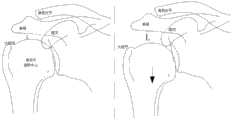
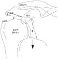
肩峰下撞击症(图8)是临床上很常见的引起肩关节疼痛和功能障碍的病症。肩峰前外侧端形态异常、骨赘形成,肱骨大结节的骨赘形成以及其他可能导致肩峰-肱骨头间距减小的原因,均可造成肩峰下结构的挤压与撞击。这种撞击大多发生在肩峰前外1/3和肱骨头(主要是肱骨大结节)之间。反复的撞击促使滑囊、肌腱发生损伤、退变,乃至发生肌腱(肩袖)断裂。撞击征的定义是:肩峰下关节由于解剖结构原因或动力学原因,在肩的上举、外展运动中,因肩峰下组织发生撞击而产生的临床症状。此类患者往往又因疼痛、炎症等而伴有不同程度的肩关节粘连,相互促进形成恶性循环。Subacromial impingement (Figure 8) is a common clinical condition that causes shoulder pain and dysfunction. Abnormal morphology of the anterolateral end of the acromion, osteophyte formation, osteophyte formation in the greater tuberosity of the humerus, and other causes that may reduce the acromion-humeral head spacing can cause compression and impingement of the subacromial structure. Most of this impingement occurs between the anterolateral third of the acromion and the humeral head (mainly the greater tuberosity of the humerus). Repeated impacts can lead to bursa, tendon damage, degeneration, and even tendon (rotator cuff) rupture. The definition of impingement sign is the clinical symptoms caused by the impingement of the subacromial tissue during the lifting and abduction movement of the subacromial joint due to anatomical structural reasons or dynamic reasons. Such patients are often accompanied by different degrees of shoulder joint adhesion due to pain, inflammation, etc., which promote each other to form a vicious circle.
目前的手术技术针对此类病灶,为了避免或者减轻撞击带来的危害,往往需要通过手术用磨头磨削去除肩峰端的骨赘(如图10中沿粗直线将部位A打磨掉),增大肩峰和肱骨头之间的距离,从而避免撞击。还有技术通过开放式手术将肩关节盂人为截断并整体下移(如图10中沿粗虚线将把关节盂截断),被截断的关节盂部位B和肱骨头一起整体下移,再用钢板固定,从而达到增大肩峰和肱骨头之间距离的目的。但这样做的创伤较大,恢复较慢。The current surgical techniques are aimed at such lesions. In order to avoid or reduce the harm caused by the impact, it is often necessary to remove the osteophytes at the acromion end by grinding with a surgical grinding head (as shown in Fig. The distance between the greater acromion and the humeral head, thus avoiding impingement. There is also a technique to artificially truncate the glenoid through open surgery and move it down as a whole (the glenoid will be truncated along the thick dotted line in Figure 10), and the truncated glenoid part B and the humeral head are moved down together as a whole, and then a steel plate is used. Fixation, so as to achieve the purpose of increasing the distance between the acromion and the humeral head. But doing so is more traumatic and slower to recover.
CN205697866U中公开的肩关节镜工作通道定位扩张器,其通过采用交叉设置左长片和右短片以实现分离撑开的目的;但是,这种装置的张合角度较大,一般都需要在肩部开一个较大的创口,会增加患者的负担,不适宜关节腔隙的撑开。The shoulder arthroscope working channel positioning expander disclosed in CN205697866U adopts the cross-arrangement of the left long piece and the right short piece to achieve the purpose of separating and spreading; Opening a larger wound will increase the burden on the patient and is not suitable for opening the joint space.
发明内容SUMMARY OF THE INVENTION
针对上述问题,本发明提供一种关节撑开器,主要解决了关节腔隙不能微创撑开等问题。In view of the above problems, the present invention provides a joint spreader, which mainly solves the problem that the joint cavity cannot be opened minimally.
为了解决上述问题,本发明采用如下技术方案:In order to solve the above problems, the present invention adopts the following technical solutions:
一种关节撑开器,包括主体件和局部位于主体件内的撑开件,所述撑开件能在主体件中沿长轴方向移动;A joint spreader, comprising a main body and a spreader partially located in the main body, the spreader can move along the long axis direction in the main body;
所述撑开件包括活动件,所述活动件的撑开端连接于撑开部,The stretcher includes a movable piece, and the stretcher end of the movable piece is connected to the stretcher,
所述撑开部远离所述撑开端的端部连接于主体件;an end of the stretched portion away from the stretched end is connected to the main body;
所述活动件相对主体件移动时带动撑开部开合。When the movable part moves relative to the main part, the opening and closing parts are driven to open and close.
一种方式,所述主体件一侧端设有容纳槽,另一侧端开设有中通的滑动腔;In one way, one side end of the main body is provided with a accommodating groove, and the other side end is provided with a middle-through sliding cavity;
所述撑开部两端均位于所述容纳槽中,Both ends of the opening portion are located in the accommodating groove,
所述撑开端穿过所述滑动腔后连接于所述撑开部。The stretched end is connected to the stretched portion after passing through the sliding cavity.
一种方式,所述容纳槽靠近所述滑动腔的一侧端设有限位槽;In one way, a limit groove is provided at one end of the accommodating groove close to the sliding cavity;
所述撑开部靠近所述撑开端的一端设有与限位槽匹配的限位块。A limit block matched with the limit groove is provided at one end of the stretched portion close to the stretched end.
一种方式,所述撑开部远离所述撑开端一端转动连接于容纳槽远离滑动腔的一端。In one way, one end of the opening portion away from the opening end is rotatably connected to an end of the accommodating slot away from the sliding cavity.
一种方式,所述撑开部由若干相互铰接的伸展部组成;所述撑开部收拢后能完全位于所述容纳槽中。In one way, the expansion part is composed of a plurality of mutually hinged extension parts; the expansion part can be completely located in the accommodating groove after being folded.
一种方式,所述主体件为中通结构,所述活动件长度大于所述主体件;In one way, the main body is a mid-pass structure, and the movable part is longer than the main body;
所述撑开端穿过所述活动腔连接于撑开部。The stretched end is connected to the stretched portion through the movable cavity.
一种方式,所述撑开部远离所述撑开端的一端连接于所述主体件的拉伸端。In one way, one end of the stretched portion away from the stretched end is connected to the stretched end of the main body.
一种方式,当所述撑开部收拢后,所述收拢部外径小于或等于所述主体件外径。In one way, after the expansion portion is folded, the outer diameter of the folded portion is smaller than or equal to the outer diameter of the main body.
一种方式,所述活动件远离所述撑开部的一端设有把手,所述主体件套设于撑开部和把手之间的活动件外,In one way, a handle is provided at one end of the movable piece away from the opening portion, and the main body is sleeved outside the movable piece between the opening portion and the handle,
所述主体件长度可调。The length of the main body is adjustable.
一种方式,所述收拢部为外立体网状结构。In one way, the collection portion is an external three-dimensional mesh structure.
一种方式,所述开部由若干个撑开单元组成,每个所述撑开单元由3个伸展部组成,位于中间的伸展部为顶撑件;In one way, the opening part is composed of several stretching units, each of the stretching units is composed of 3 stretching parts, and the stretching part in the middle is a top support;
其中一个伸展部的一端连接于撑开件,另一端铰接于顶撑件,One end of one of the extension parts is connected to the opening piece, and the other end is hinged to the top support piece,
另一个伸展部的一端连接于主体件,另一端铰接于顶撑件。One end of the other extension is connected to the main body, and the other end is hinged to the top support.
本发明的有益效果是:The beneficial effects of the present invention are:
1.实现了如图9中关节旋转中心下移,改变局部解剖关系,增加关节间隙,从而避免撞击的目的;1. As shown in Figure 9, the joint rotation center is moved down, the local anatomical relationship is changed, the joint space is increased, and the purpose of avoiding collision;
2.收拢时设备整体外径较小,可以实现从小创口进入关节腔隙内部,在内部进行局部展开,实现了微创操作,降低了患者的负担;2. When folded, the overall outer diameter of the device is small, which can enter the joint cavity from a small wound, and carry out partial deployment inside, which realizes the minimally invasive operation and reduces the burden on the patient;
3.利用机械原理进行撑开,保障了撑开的可靠性、可控性。3. The mechanical principle is used to stretch, which ensures the reliability and controllability of the stretch.
附图说明Description of drawings
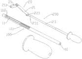
图1为本发明实施例1的爆照结构示意图;Fig. 1 is the exploded photograph structure schematic diagram of Embodiment 1 of the present invention;
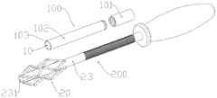
图2为本发明实施例1的局部结构示意图;Fig. 2 is the partial structure schematic diagram of Embodiment 1 of the present invention;
图3为本发明实施例1局部组装结构示意图;3 is a schematic diagram of a partial assembly structure of Embodiment 1 of the present invention;
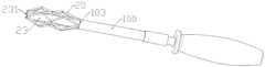
图4-5为本发明实施例2结构示意图;4-5 are schematic structural diagrams of Embodiment 2 of the present invention;
图6为本发明实施例3的结构示意图;6 is a schematic structural diagram of Embodiment 3 of the present invention;
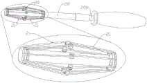
图7为为本发明实施例4结构示意图;7 is a schematic structural diagram of Embodiment 4 of the present invention;
图8为肩关节撞击模式图;Fig. 8 is the shoulder joint impingement pattern diagram;
图9肩关节旋转中心下移情况说明示意图;Fig. 9 is a schematic diagram for explaining the downward movement of the rotation center of the shoulder joint;
图10为现有病症一些解决方案示意图。Figure 10 is a schematic diagram of some solutions for existing diseases.
图中:In the picture:
100主体件,200撑开件,10滑动腔,11容纳槽,101第一主体件,102第二主体件,111限位槽,101拉伸端,112转动凹槽,20撑开部,21伸展部,211转动件,221限位块,23活动件,231撑开端。100 main body part, 200 spreading part, 10 sliding cavity, 11 receiving groove, 101 first main body part, 102 second main body part, 111 limiting groove, 101 stretching end, 112 rotating groove, 20 opening part, 21 Extending part, 211 rotating part, 221 limit block, 23 movable part, 231 open end.
具体实施方式Detailed ways
下面结合附图对本发明进行进一步说明:The present invention will be further described below in conjunction with the accompanying drawings:
一种关节撑开器,包括主体件100和局部位于主体件100内的撑开件200,所述撑开件200能在主体件100中沿长轴方向移动;A joint spreader, comprising a
所述撑开件200包括活动件23,所述活动件23的撑开端231连接于撑开部20,The
所述撑开部20远离所述撑开端231的端部连接于主体件100;The end of the
所述活动件23相对主体件100移动时带动撑开部20开合。When the
实施例1Example 1
如图1-3所示,其中,所述主体件100一侧端设有容纳槽11,另一侧端开设有中通的滑动腔10;As shown in Figures 1-3, wherein, one end of the
所述撑开部20两端均位于所述容纳槽11中,Both ends of the opening
所述撑开端231穿过所述滑动腔10后连接于所述撑开部20。The
所述容纳槽11靠近所述滑动腔10的一侧端设有限位槽111;A limiting
所述撑开部20靠近所述撑开端231的一端设有与限位槽111匹配的限位块221。A limiting
所述撑开部20远离所述撑开端231一端转动连接于容纳槽11远离滑动腔10的一端。One end of the opening
所述撑开部20由若干相互铰接的伸展部21组成;所述撑开部20收拢后能完全位于所述容纳槽11中。The expanding
本实施例一种使用方法为:A method of using this embodiment is:
如图3中,使用时,撑开部20一端转动设置在容纳槽11远端,另一端能够沿着长条形的限位槽111在互动;当将活动件23向远端推动时,撑开端231向远端推动,由于撑开部20远端通过转动件211和转动凹槽112转动设置,在撑开端231向远端推移时,会使得撑开部20形变,撑开部20向容纳槽11外侧弯曲;从而实现撑开部20的撑开。As shown in FIG. 3 , during use, one end of the opening
实施例2Example 2
如图4-5所示,其中,所述主体件100为中通结构,所述活动件23长度大于所述主体件100;As shown in FIGS. 4-5 , wherein, the
所述撑开端231穿过所述活动腔10连接于撑开部20。The
所述撑开部20远离所述撑开端231的一端连接于所述主体件100的拉伸端103。One end of the opening
当所述撑开部20收拢后,所述撑开部20外径小于或等于所述主体件100外径。After the
所述活动件23远离所述撑开部20的一端设有把手,所述主体件100套设于撑开部20和把手之间的活动件23外,A handle is provided at one end of the
所述主体件100的第一主体件101和第二主体件102转动连接,两者能相对转动;The first
第一主体件101和撑开件200也螺纹连接,通过转动第一主体件101可以调节第一主体件101在撑开件200上的位置,从而实现连带的带动第二主体件102沿长轴方向移动,同时由于第一主体件101和第二主体件102转动连接,不会带动第二主体件102转动。The first
通过螺纹旋接的方式可以实现第一主体件101在撑开件200移动距离的连续调节(即可以实现到达任意距离停止),进一步是可以实现撑开部20撑开角度的连续调节,并且自身具有较好的紧固作用,不易自行向手柄端移动。Continuous adjustment of the moving distance of the first
所述撑开部20为外立体网状结构。The expanding
所述撑开部20远离所述撑开端231一端转动连接于容纳槽11远离滑动腔10的一端;One end of the opening
撑开部20通过自身的转动件211插设于容纳槽11中的转动凹槽112中实现连接。The opening
本实施例一种使用方法为:A method of using this embodiment is:
如图5中所示,当转动第一主体件101使得主体件100向远端移动后撑开件200远端移动后,拉伸端103将撑开部20近端向远端挤压,从而使得撑开部20向外张开,使得撑开部20外径增加,起到撑开的作用。As shown in FIG. 5 , when the first
实施例3Example 3
如图6中所示,在本实施例中,主体结构类同实施例2,立体网状结构的撑开部20有若干撑开单元组成,每个撑开单元由相互铰接的伸展部21组成,在撑开时,每个撑开单元各自撑开。As shown in FIG. 6 , in this embodiment, the main body structure is similar to that of Embodiment 2, and the opening
本实施例一种使用方法为:A method of using this embodiment is:
当转动第一主体件101使得主体件100向远端移动后撑开件200远端移动后,拉伸端103将撑开部20近端向远端挤压,从而使得相互铰接的伸展部21远端距离缩小,从而实现伸展部21局部向外撑开,使得撑开部20外径增加,起到撑开的作用。When the first
实施例4Example 4
如图7中所示,所述开部20由若干个撑开单元组成,每个所述撑开单元由3个伸展部21组成;As shown in FIG. 7 , the opening
在一个撑开单元中,位于中间的伸展部21为顶撑件,In a spreading unit, the
两侧的伸展部21中,其中一个伸展部21的一端连接于撑开件200,另一端铰接于顶撑件,Among the
另一个伸展部21的一端连接于主体件100,另一端铰接于顶撑件。One end of the
本实施例一种使用方法为:A method of using this embodiment is:
顶撑件具有一个较为平整的顶撑平面,当撑开件200向伸展部21移动时,两端的伸展部21将中间的顶撑件向外挤压,实现撑开,三个伸展部21均撑开,其中中间的顶撑件的顶撑平面能更好的起到支撑顶起作用。The top supporter has a relatively flat top support plane. When the
如图9中,使用撑开件后,肱骨头整体下移,肩关节旋转中心整体被动下移,同样可以达到增加肱骨大结节和肩峰之间的距离L的目的。As shown in Figure 9, after using the spacer, the humeral head moves down as a whole, and the shoulder joint rotation center moves down passively as a whole, which can also achieve the purpose of increasing the distance L between the greater tuberosity of the humerus and the acromion.
为了实现如图9中所示肩关节旋转中心下移,需要撑开达到一种微病理状态,也就是肩关节处于一种半脱位的病理状态,这对撑开器力学性能有特殊的要求,撑开以后力学特性的保持,需要采用阻挡件,本发明囊状结构是为了阻止关节回缩,对阻挡件的尺寸有要求。而为了满足这样的目的,需要比生理性粘液囊厚的阻挡件,需要的结构中部更厚,边缘收拢的结构。In order to realize the downward movement of the rotation center of the shoulder joint as shown in Figure 9, it is necessary to stretch to achieve a micro-pathological state, that is, the shoulder joint is in a pathological state of subluxation, which has special requirements for the mechanical properties of the spreader. The maintenance of the mechanical properties after the expansion requires the use of a blocking member. The capsule structure of the present invention is to prevent the joint from retracting, and the size of the blocking member is required. In order to meet such a purpose, a thicker blocker than the physiological bursa is required, and a structure with a thicker middle part and a gathered edge structure is required.
本发明结合阻挡件(“一种关节阻挡装置”另案申请)的一种使用方法为:A method of using the present invention in combination with a blocking member ("a joint blocking device" filed separately) is:
患者预先拍摄局部的1:1的X线平片,并进行测量。确定皮肤切口到预订撑开部位的距离;本发明的撑开器的撑开部预先收缩,前端有刻度标识;局部消毒后,配合局部浸润麻醉条件下,将撑开器插入体内需要撑开的部位,通过X线机或者B超定位再次确认是否到达预订部位,然后术者控制撑开器撑开;此时关节囊会发生局部的微撕裂,从而实现肩关节旋转中心的下移,一般应使肩关节旋转中心下移1cm左右为宜;The patient pre-takes local 1:1 plain radiographs and measures. Determine the distance from the skin incision to the predetermined opening position; the opening part of the opening device of the present invention is pre-contracted, and the front end has a scale mark; after local disinfection, under the condition of local infiltration anesthesia, the opening device is inserted into the body to be opened. At this time, a local micro-tear will occur in the joint capsule, so that the center of rotation of the shoulder joint can be moved down, generally It is advisable to move the center of rotation of the shoulder joint down by about 1cm;
完成上述步骤以后,将阻挡件放入体内,并注水(生理盐水)填充,充满间隙,避免微撕裂的关节囊组织再次回缩,再次形成撞击;After completing the above steps, put the blocking piece into the body, and fill it with water (physiological saline) to fill the gap, so as to avoid the micro-torn joint capsule tissue from retracting again and forming an impact again;
局部发生微撕裂的关节囊组织会在新的解剖关系中愈合,部分膨胀体201中的药物也有助于撕裂部位愈合,以适应新的解剖关系,这种状态持续足够长的时间以后,整个肩部的解剖形态会适应,从而避免再次撞击。The joint capsule tissue where the micro-tear occurs locally will heal in the new anatomical relationship, and the drugs in the partial expansion body 201 also help the tear site heal to adapt to the new anatomical relationship. After this state persists for a long enough time, The anatomy of the entire shoulder adapts to avoid re-impacting.
本领域的技术人员可以明确,在不脱离本发明的总体精神以及构思的情形下,可以做出对于以上实施例的各种变型。其均落入本发明的保护范围之内。本发明的保护方案以本发明所附的权利要求书为准。It will be apparent to those skilled in the art that various modifications to the above embodiments can be made without departing from the general spirit and concept of the present invention. All of them fall within the protection scope of the present invention. The protection scheme of the present invention is subject to the appended claims of the present invention.
Claims (11)
Priority Applications (1)
| Application Number | Priority Date | Filing Date | Title |
|---|---|---|---|
| CN202010090715.6ACN111281450A (en) | 2020-02-13 | 2020-02-13 | Joint spreader |
Applications Claiming Priority (1)
| Application Number | Priority Date | Filing Date | Title |
|---|---|---|---|
| CN202010090715.6ACN111281450A (en) | 2020-02-13 | 2020-02-13 | Joint spreader |
Publications (1)
| Publication Number | Publication Date |
|---|---|
| CN111281450Atrue CN111281450A (en) | 2020-06-16 |
Family
ID=71024433
Family Applications (1)
| Application Number | Title | Priority Date | Filing Date |
|---|---|---|---|
| CN202010090715.6APendingCN111281450A (en) | 2020-02-13 | 2020-02-13 | Joint spreader |
Country Status (1)
| Country | Link |
|---|---|
| CN (1) | CN111281450A (en) |
Cited By (1)
| Publication number | Priority date | Publication date | Assignee | Title |
|---|---|---|---|---|
| CN116035633A (en)* | 2022-12-14 | 2023-05-02 | 青岛市城阳区人民医院 | Knee joint spreader |
Citations (7)
| Publication number | Priority date | Publication date | Assignee | Title |
|---|---|---|---|---|
| US5345927A (en)* | 1990-03-02 | 1994-09-13 | Bonutti Peter M | Arthroscopic retractors |
| CN206102682U (en)* | 2016-06-30 | 2017-04-19 | 武汉科技大学附属天佑医院 | Soft tissue clearance struts ware |
| CN206261625U (en)* | 2016-08-10 | 2017-06-20 | 邹德威 | Dilator |
| CN208988981U (en)* | 2017-12-15 | 2019-06-18 | 山东大学 | An abdominal wall spreader |
| CN209285596U (en)* | 2018-10-10 | 2019-08-23 | 苏州微创骨科医疗工具有限公司 | Intervertebral opening device |
| CN110301947A (en)* | 2019-05-30 | 2019-10-08 | 中国医学科学院北京协和医院 | Laparoscope undertissue dilator |
| CN212574907U (en)* | 2020-02-13 | 2021-02-23 | 华中科技大学同济医学院附属协和医院 | A joint spreader |
- 2020
- 2020-02-13CNCN202010090715.6Apatent/CN111281450A/enactivePending
Patent Citations (7)
| Publication number | Priority date | Publication date | Assignee | Title |
|---|---|---|---|---|
| US5345927A (en)* | 1990-03-02 | 1994-09-13 | Bonutti Peter M | Arthroscopic retractors |
| CN206102682U (en)* | 2016-06-30 | 2017-04-19 | 武汉科技大学附属天佑医院 | Soft tissue clearance struts ware |
| CN206261625U (en)* | 2016-08-10 | 2017-06-20 | 邹德威 | Dilator |
| CN208988981U (en)* | 2017-12-15 | 2019-06-18 | 山东大学 | An abdominal wall spreader |
| CN209285596U (en)* | 2018-10-10 | 2019-08-23 | 苏州微创骨科医疗工具有限公司 | Intervertebral opening device |
| CN110301947A (en)* | 2019-05-30 | 2019-10-08 | 中国医学科学院北京协和医院 | Laparoscope undertissue dilator |
| CN212574907U (en)* | 2020-02-13 | 2021-02-23 | 华中科技大学同济医学院附属协和医院 | A joint spreader |
Cited By (2)
| Publication number | Priority date | Publication date | Assignee | Title |
|---|---|---|---|---|
| CN116035633A (en)* | 2022-12-14 | 2023-05-02 | 青岛市城阳区人民医院 | Knee joint spreader |
| CN116035633B (en)* | 2022-12-14 | 2023-11-07 | 青岛市城阳区人民医院 | Knee joint spreader |
Similar Documents
| Publication | Publication Date | Title |
|---|---|---|
| US10449031B2 (en) | Methods and apparatus for delivering and positioning sheet-like materials | |
| US6869398B2 (en) | Four-blade surgical speculum | |
| US20140114331A1 (en) | X-Shaped Device and Method for Deployment and Placement of a Patch | |
| Chung et al. | Laparoscopic-assisted total mesorectal excision and colonic J pouch reconstruction in the treatment of rectal cancer | |
| ES3026564T3 (en) | Device for the retraction of soft tissue in a patient undergoing arthroscopic surgery | |
| Sandler et al. | The use of endoscopy in the management of subcondylar fractures of the mandibleA cadaver study | |
| CN111281450A (en) | Joint spreader | |
| CN104546035B (en) | Anorectum jacking and fixing device and method | |
| CN106667644B (en) | A kind of Multifunctional infant supracondylar fracture of humerus auxiliary external fixation device | |
| CN222383268U (en) | Surgical field expander for orthopedic minimally invasive surgery | |
| CN110623717B (en) | Intramedullary nail capable of being unfolded and fixed | |
| RU2312633C2 (en) | Method for treating chronic brachial luxations | |
| CN212574907U (en) | A joint spreader | |
| KR101318863B1 (en) | Apparatus for extension of bone | |
| CN211560385U (en) | Liver blocking device for laparoscopic surgery | |
| Moriyama et al. | Endoscopic endonasal treatment of ostium of the frontal sinus and the results of endoscopic surgery | |
| CN113197647A (en) | Proximal radius lateral bone fracture plate | |
| Schipper et al. | Lateral upper arm free flap for primary reconstruction of pharyngeal defects in ablative oncological surgery: Report of six consecutive cases | |
| CN205569029U (en) | Intestines and stomach mirror pincers way surgical instruments | |
| RU2469663C1 (en) | Method for surgical procedure of neck organs and apparatus for creating surgical space when implementing it | |
| CN206499564U (en) | A kind of Multifunctional infant supracondylar fracture of humerus aids in external fixation device | |
| CN109394283A (en) | A kind of gynecological surgery stretching pliers | |
| CN204445967U (en) | Fixture is lifted on anorectum top | |
| CN221617223U (en) | A posterior ankle fracture reducer | |
| CN111281449B (en) | Joint blocking device |
Legal Events
| Date | Code | Title | Description |
|---|---|---|---|
| PB01 | Publication | ||
| PB01 | Publication | ||
| SE01 | Entry into force of request for substantive examination | ||
| SE01 | Entry into force of request for substantive examination |