Movatterモバイル変換


[0]ホーム

URL:


CN111278372A - Cannula attachment apparatus and method for surgical robotic systems - Google Patents

Cannula attachment apparatus and method for surgical robotic systems
Download PDF

Info

Publication number
CN111278372A
CN111278372ACN201880054545.7ACN201880054545ACN111278372ACN 111278372 ACN111278372 ACN 111278372ACN 201880054545 ACN201880054545 ACN 201880054545ACN 111278372 ACN111278372 ACN 111278372A
Authority
CN
China
Prior art keywords
cannula
clamp member
clamp
locking
locking member
Prior art date
Legal status (The legal status is an assumption and is not a legal conclusion. Google has not performed a legal analysis and makes no representation as to the accuracy of the status listed.)
Granted
Application number
CN201880054545.7A
Other languages
Chinese (zh)
Other versions
CN111278372B (en
Inventor
C.J.谢布
Current Assignee (The listed assignees may be inaccurate. Google has not performed a legal analysis and makes no representation or warranty as to the accuracy of the list.)
Verb Surgical Inc
Original Assignee
Verb Surgical Inc
Priority date (The priority date is an assumption and is not a legal conclusion. Google has not performed a legal analysis and makes no representation as to the accuracy of the date listed.)
Filing date
Publication date
Application filed by Verb Surgical IncfiledCriticalVerb Surgical Inc
Publication of CN111278372ApublicationCriticalpatent/CN111278372A/en
Application grantedgrantedCritical
Publication of CN111278372BpublicationCriticalpatent/CN111278372B/en
Activelegal-statusCriticalCurrent
Anticipated expirationlegal-statusCritical

Links

Images

Classifications

Landscapes

Abstract

Translated fromChinese

本发明提供一种机器人外科系统,所述机器人外科系统可包括具有锁定机构的插管附接设备或插管安装件,所述锁定机构被构造成在解锁位置和锁定偏心位置之间枢转。所述锁定机构可致动夹具或其他被构造成在闭合位置和打开位置之间移动的特征。所述夹具可包括具有一个或多个锥形表面的定位结构,所述定位结构被构造成当插管位于所述插管附接设备中时,与设置在所述插管的一部分上的对应结构配合。所述定位结构可将所述插管引导到所述附接设备中,并且有助于相对于所述附接设备对所述插管进行取向。

Figure 201880054545

The present invention provides a robotic surgical system that can include a cannula attachment device or cannula mount having a locking mechanism configured to pivot between an unlocked position and a locked off-center position. The locking mechanism may actuate a clamp or other feature configured to move between a closed position and an open position. The clamp may include a locating feature having one or more tapered surfaces, the locating feature being configured to correspond to a position provided on a portion of the cannula when the cannula is in the cannula attachment device Structural fit. The positioning structure may guide the cannula into the attachment device and facilitate orientation of the cannula relative to the attachment device.

Figure 201880054545

Description

Translated fromChinese
用于外科机器人系统的插管附接设备和方法Cannula attachment apparatus and method for surgical robotic systems

交叉引用和相关申请Cross-references and related applications

本申请要求2017年8月21日提交的美国临时专利申请序列号62/548,292的优先权,该申请据此全文以引用方式并入本文。This application claims priority to US Provisional Patent Application Serial No. 62/548,292, filed August 21, 2017, which is hereby incorporated by reference in its entirety.

技术领域technical field

本发明整体涉及机器人外科系统,并且更具体地讲,涉及用于将无菌部件附接到机器人外科系统的一个或多个非无菌部件的新且有用的附接设备和方法。The present invention relates generally to robotic surgical systems, and more particularly, to new and useful attachment apparatus and methods for attaching sterile components to one or more non-sterile components of a robotic surgical system.

背景技术Background technique

微创外科手术(MIS)诸如腹腔镜式外科手术涉及旨在外科规程期间减少组织损伤的技术。例如,腹腔镜式规程通常涉及在患者体内(例如,在腹腔内)形成许多小切口,并且通过这些切口将一个或多个工具和至少一个相机引入至患者中。然后,通过使用所引入的工具和由相机提供的可视化辅助来执行外科规程。一般来讲,MIS提供多种有益效果,诸如减少患者瘢痕、减轻患者疼痛、缩短患者恢复期并且降低与患者恢复相关联的医疗费用。Minimally invasive surgical procedures (MIS) such as laparoscopic surgery involve techniques aimed at reducing tissue damage during surgical procedures. For example, laparoscopic procedures typically involve making a number of small incisions within a patient's body (eg, within the abdominal cavity) and introducing one or more tools and at least one camera into the patient through these incisions. Surgical procedures are then performed using the introduced tools and visualization aids provided by the cameras. In general, MIS provides a variety of beneficial effects, such as reducing patient scarring, reducing patient pain, shortening patient recovery periods, and reducing medical costs associated with patient recovery.

MIS可以使用非机器人或机器人系统来执行。传统的机器人系统可包括基于来自操作者的命令操纵工具的机器人臂,可以在减少对外科医生的需求的同时提供MIS的许多有益效果。此类机器人系统的控制可能需要用户(例如,外科医生或其他操作者)经由一个或多个用户接口设备进行控制输入,该一个或多个用户接口设备将用户的操纵或命令转化为对机器人系统的控制。例如,响应于用户命令,当外科工具定位在患者的外科部位时,具有一个或多个电机的工具驱动器可以致动外科工具的一个或多个自由度。MIS can be performed using non-robotic or robotic systems. Conventional robotic systems, which can include robotic arms that manipulate tools based on commands from an operator, can provide many of the benefits of MIS while reducing the need for a surgeon. Control of such robotic systems may require control input from the user (eg, a surgeon or other operator) via one or more user interface devices that translate the user's manipulations or commands into the robotic system. control. For example, in response to a user command, a tool driver with one or more motors may actuate one or more degrees of freedom of the surgical tool when the surgical tool is positioned at the surgical site of the patient.

在机器人MIS期间,外科医生或其他操作者可使用多种不同的外科器械在外科部位进行规程。通常,外科医生可依靠使用套管针或插管来靶向患者的身体内的某个部位。插管可提供通道或开口,外科医生可通过该通道或开口来引入和移除附加的外科器械。例如,可将插管定位在患者内的体腔中,并且可将外科器械插入插管中并经由插管引导到体腔。在机器人系统中,可将插管安装到一个或多个机器人臂,外科医生可远程控制这些机器人臂来移动插管。可使用插管安装件来将插管附接到机器人臂,以确保插管在患者内的正确控制和放置。然而,许多常规的插管安装件的尺寸都很小,并且它们可承载的负载有限。这些插管安装件可使用复杂的闩锁系统来将插管相对于机器人臂固定在适当的位置,但它们可能难以使用并且对插管尺寸的变化敏感。与传统的外科规程类似,在机器人MIS期间,在外科区域保持无菌环境也非常重要。考虑到这些有待改进的领域,希望在机器人外科系统中具有新且改进的插管安装件和附接方法。During robotic MIS, a surgeon or other operator may perform procedures at the surgical site using a variety of different surgical instruments. Often, a surgeon may rely on the use of a trocar or cannula to target a certain site within a patient's body. The cannula may provide a channel or opening through which the surgeon may introduce and remove additional surgical instruments. For example, a cannula can be positioned in a body cavity within a patient, and a surgical instrument can be inserted into the cannula and guided through the cannula to the body cavity. In a robotic system, the cannula can be mounted to one or more robotic arms that the surgeon can remotely control to move the cannula. A cannula mount can be used to attach the cannula to the robotic arm to ensure proper control and placement of the cannula within the patient. However, many conventional cannula mounts are small in size and the loads they can carry are limited. These cannula mounts can use complex latching systems to hold the cannula in place relative to the robotic arm, but they can be difficult to use and sensitive to changes in cannula size. Similar to traditional surgical procedures, maintaining a sterile environment in the surgical field is also very important during robotic MIS. Given these areas for improvement, it would be desirable to have new and improved cannula mounts and attachment methods in robotic surgical systems.

发明内容SUMMARY OF THE INVENTION

一般来讲,在一些变型中,机器人外科系统可包括用于将插管附接到外科系统的装置。该装置可具有彼此隔开的第一夹具部件和第二夹具部件。第一夹具部件可被构造成在打开位置和闭合位置之间枢转。第一夹具部件和第二夹具部件可限定用于接纳插管的一部分的区域。当第一夹具部件处于闭合位置时,第一夹具部件和第二夹具部件可将插管的该部分保持在第一夹具部件和第二夹具部件之间的区域内。该装置还可具有锁定部件,该锁定部件联接到第一夹具部件并且被构造成使第一夹具部件在打开位置和闭合位置之间枢转。附加地或另选地,锁定部件可联接到第二夹具部件。Generally, in some variations, a robotic surgical system may include means for attaching a cannula to the surgical system. The device may have a first clamp part and a second clamp part spaced apart from each other. The first clamp member may be configured to pivot between an open position and a closed position. The first clamp member and the second clamp member may define an area for receiving a portion of the cannula. When the first clamp part is in the closed position, the first clamp part and the second clamp part can hold the portion of the cannula in the area between the first clamp part and the second clamp part. The device may also have a locking member coupled to the first clamp member and configured to pivot the first clamp member between an open position and a closed position. Additionally or alternatively, the locking member may be coupled to the second clamp member.

在一些变型中,锁定部件可在解锁位置和锁定位置之间枢转。锁定位置可例如为锁定偏心位置。当锁定部件处于解锁位置时,第一夹具部件可处于打开位置,并且当锁定部件处于锁定位置时,第一夹具部件可处于闭合位置。锁定部件可被构造成当锁定部件处于锁定位置时,将第一夹具部件锁定在闭合位置。例如,当锁定部件处于锁定位置时,可将锁定部件朝向锁定位置偏置。在一些变型中,机器人外科系统和/或附接装置可包括弹簧,该弹簧被构造成将第一夹具部件偏置在闭合位置。In some variations, the locking member is pivotable between an unlocked position and a locked position. The locked position may be, for example, a locked off-center position. When the locking member is in the unlocked position, the first clamp member may be in the open position, and when the locking member is in the locked position, the first clamp member may be in the closed position. The locking member may be configured to lock the first clamp member in the closed position when the locking member is in the locking position. For example, when the locking member is in the locked position, the locking member may be biased towards the locked position. In some variations, the robotic surgical system and/or attachment device may include a spring configured to bias the first clamp member in the closed position.

在一些变型中,第一夹具部件可具有狭槽,该狭槽沿着第一夹具部件的部分长度延伸。锁定部件的第一端部可设置在第一夹具部件的狭槽中并且可沿着该狭槽的长度移动,并且锁定部件的第二端部可移动以使锁定部件在解锁位置和锁定偏心位置之间枢转。当锁定部件从解锁位置枢转到锁定偏心位置时,锁定部件的第一端部可沿着狭槽在第一方向上移动,并且当锁定部件从锁定偏心位置枢转到解锁位置时,锁定部件的第一端部可沿着狭槽在与第一方向相反的第二方向上移动。In some variations, the first clamp member may have a slot extending along a portion of the length of the first clamp member. The first end of the locking member is displaceable in the slot of the first clamp member and is movable along the length of the slot, and the second end of the locking member is movable to place the locking member in the unlocked position and the locking off-center position pivot between. The first end of the locking member is movable in a first direction along the slot when the locking member is pivoted from the unlocked position to the locking eccentric position, and when the locking member is pivoted from the locking eccentric position to the unlocked position, the locking member The first end of the is movable along the slot in a second direction opposite the first direction.

在一些变型中,第一夹具部件和第二夹具部件中的至少一个可包括定位结构,该定位结构被构造成与设置在插管的部分上的对应结构配合。定位结构可被构造成将插管的部分相对于第一夹具部件和第二夹具部件以预定取向引导到第一夹具部件和第二夹具部件之间的区域中。在一些变型中,定位结构包括第一锥形表面和第二锥形表面,其中这两个锥形表面形成三角形突起。该三角形突起可被构造成当第一夹具部件处于闭合位置时,闩锁到插管的部分中并将插管的部分保持在由第一夹具部件和第二夹具部件限定的区域内。在其他变型中,定位结构可为其他合适的形状,诸如大体截头棱锥形。In some variations, at least one of the first clamp member and the second clamp member may include a locating structure configured to cooperate with a corresponding structure provided on a portion of the cannula. The positioning structure may be configured to guide the portion of the cannula in a predetermined orientation relative to the first clamp member and the second clamp member into the region between the first clamp member and the second clamp member. In some variations, the locating structure includes a first tapered surface and a second tapered surface, wherein the two tapered surfaces form a triangular protrusion. The triangular protrusion may be configured to latch into and retain the portion of the cannula within the area defined by the first clamp member and the second clamp member when the first clamp member is in the closed position. In other variations, the locating structures may be other suitable shapes, such as generally frusto-pyramidal shapes.

在一些变型中,机器人外科系统和/或附接装置还可包括无菌屏障,该无菌屏障将附接装置的第一夹具部件和第二夹具部件与插管分开。无菌屏障可将外科系统的非无菌部件(诸如第一夹具部件和第二夹具部件)与外科系统的无菌部件(包括插管)分开。In some variations, the robotic surgical system and/or the attachment device may also include a sterile barrier separating the first and second clamp members of the attachment device from the cannula. The sterile barrier can separate non-sterile components of the surgical system, such as the first and second clip components, from sterile components of the surgical system, including the cannula.

在一些变型中,方法可包括:将用于插管的附接装置的锁定部件定位在解锁位置;将插管的一部分插入第一夹具部件和第二夹具部件之间的区域中;以及将锁定部件从解锁位置移动到锁定偏心位置。锁定部件可操作地联接到第一夹具部件并且被构造成使第一夹具部件在打开位置和闭合位置之间枢转;因此,将锁定部件从解锁位置移动到锁定偏心位置可使第一夹具部件枢转到闭合位置,使得第一夹具部件和第二夹具部件被构造成将插管的部分保持在第一夹具部件和第二夹具部件之间的区域中。In some variations, the method may include: positioning a locking member of the attachment device for the cannula in an unlocked position; inserting a portion of the cannula into the area between the first clamp member and the second clamp member; and placing the locking The part moves from the unlocked position to the locked off-center position. The locking member is operably coupled to the first clamp member and is configured to pivot the first clamp member between an open position and a closed position; thus, moving the locking member from the unlocked position to the locked off-center position may cause the first clamp member to pivot Pivoting to the closed position causes the first and second clamp members to be configured to retain the portion of the cannula in the area between the first and second clamp members.

附图说明Description of drawings

图1为联接到机器人臂的插管和外科器械的示例性变型的示意图。1 is a schematic diagram of an exemplary variation of a cannula and surgical instrument coupled to a robotic arm.

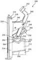
图2A为插管附接设备或插管安装件的示例性变型的透视图。图2B为如从不同角度示出的图2A所示的插管附接设备的另一透视图。图2C为如从不同角度示出的图2A所示的插管附接设备的另一透视图。2A is a perspective view of an exemplary variation of a cannula attachment device or cannula mount. 2B is another perspective view of the cannula attachment device shown in FIG. 2A as shown from a different angle. Figure 2C is another perspective view of the cannula attachment device shown in Figure 2A as shown from a different angle.

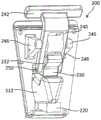
图3为插管附接系统的示例性变型的分解图,该插管附接系统包括插管、无菌屏障和图2所示的插管附接设备。3 is an exploded view of an exemplary variation of a cannula attachment system including a cannula, a sterile barrier, and the cannula attachment device shown in FIG. 2 .

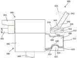
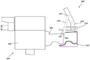
图4A为图3所示的插管附接系统的透视图,其中无菌屏障与插管附接设备接合。图4B为图3所示的插管附接系统的透视图,其中插管的一部分插入插管附接设备内。4A is a perspective view of the cannula attachment system shown in FIG. 3 with a sterile barrier engaged with a cannula attachment device. 4B is a perspective view of the cannula attachment system shown in FIG. 3 with a portion of the cannula inserted into the cannula attachment device.

图5A、图5B和图5C示出处于三种不同构型的图2A的插管附接设备。5A, 5B, and 5C illustrate the cannula attachment device of FIG. 2A in three different configurations.

图6示出图2A的插管附接设备的偏心布置。Figure 6 shows an eccentric arrangement of the cannula attachment device of Figure 2A.

图7A和图7B为插管附接设备的另一示例性变型的示意图。图7A示出处于第一构型的插管附接设备,并且图7B示出处于第二构型的插管附接设备。7A and 7B are schematic diagrams of another exemplary variation of a cannula attachment device. Figure 7A shows the cannula attachment device in a first configuration, and Figure 7B shows the cannula attachment device in a second configuration.

图8为插管附接设备的另一示例性变型的示意图,该插管附接设备包括用于移动锁定部件的机构。8 is a schematic diagram of another exemplary variation of a cannula attachment device that includes a mechanism for moving a locking member.

图9A为具有定位结构的插管附接设备的夹具部件的示例性变型的示意图。图9B为图9A所示的夹具部件的侧视图。9A is a schematic diagram of an exemplary variation of a clamp component of a cannula attachment device having a positioning feature. Figure 9B is a side view of the clamp component shown in Figure 9A.

图10为插管附接设备的另一示例性变型的示意图。10 is a schematic diagram of another exemplary variation of a cannula attachment device.

图11为插管附接设备的另一示例性变型的示意图。11 is a schematic diagram of another exemplary variation of a cannula attachment device.

图12为插管附接设备的另一示例性变型的示意图。12 is a schematic diagram of another exemplary variation of a cannula attachment device.

图13为插管附接设备的另一示例性变型的示意图。13 is a schematic diagram of another exemplary variation of a cannula attachment device.

图14为插管附接设备的另一示例性变型的示意图。14 is a schematic diagram of another exemplary variation of a cannula attachment device.

图15A为处于第一构型的图14所示的插管附接设备的附接区域的放大视图。图15B为处于第二构型的图14所示的插管附接设备的附接区域的放大视图。15A is an enlarged view of the attachment area of the cannula attachment device shown in FIG. 14 in a first configuration. 15B is an enlarged view of the attachment area of the cannula attachment device shown in FIG. 14 in a second configuration.

图16为使用插管附接设备将插管附接到机器人外科系统的示例性方法的流程图。16 is a flowchart of an exemplary method of attaching a cannula to a robotic surgical system using a cannula attachment device.

具体实施方式Detailed ways

本发明的各方面和变型形式的示例在本文中进行描述并示出于附图。以下描述不旨在将本发明限制于这些实施方案,而是允许本领域的技术人员来制作和使用本发明。Examples of aspects and variations of the invention are described herein and illustrated in the accompanying drawings. The following description is not intended to limit the invention to these embodiments, but rather to enable those skilled in the art to make and use the invention.

一般来讲,(例如,用于实现微创外科规程的)机器人或机器人辅助外科系统可诸如在微创外科手术期间包括用于操纵外科器械的一个或多个机器人臂。例如,如图1的示例性示意图所示,机器人外科系统100的一部分可包括机器人臂110和大体附接到机器人臂110的远侧端部的器械驱动器或致动器120。插管130可联接到器械驱动器120或者机器人臂110的靠近器械驱动器120设置的一部分。插管130可具有管腔,可通过该管腔接纳外科器械150。此外,机器人臂110可包括多个连杆,这些连杆被致动以便相对于患者的身体对器械驱动器120、插管130和/或外科器械150进行定位和取向。In general, robotic or robotic-assisted surgical systems (eg, used to implement minimally invasive surgical procedures) may include one or more robotic arms for manipulating surgical instruments, such as during minimally invasive surgical procedures. For example, as shown in the exemplary schematic diagram of FIG. 1 , a portion of roboticsurgical system 100 may includerobotic arm 110 and an instrument driver oractuator 120 generally attached to the distal end ofrobotic arm 110 . Thecannula 130 may be coupled to theinstrument driver 120 or a portion of therobotic arm 110 disposed proximate theinstrument driver 120 .Cannula 130 may have a lumen through whichsurgical instrument 150 may be received. Additionally,robotic arm 110 may include a plurality of links that are actuated to position and orientinstrument driver 120,cannula 130, and/orsurgical instrument 150 relative to the patient's body.

为了在外科规程中使用,机器人臂110可被安装到患者所躺的手术台上(或在患者附近的推车、天花板、侧壁等上)。为了形成能够将外科器械引入患者中的孔口,可将套管针组件通过患者的切口或进入点(例如,在腹壁中)至少部分地插入患者中。套管针组件可包括插管130、填塞器和/或密封件。在一些变型中,套管针组件可包括填塞器,诸如具有尖锐尖端的针,用于穿透患者的皮肤。当将插管130插入患者中时,可将填塞器设置在该插管的管腔内,并且然后从插管130移除,使得可通过插管130的管腔插入外科器械。一旦定位在患者的身体内,插管130就可提供用于进入患者内的体腔或其他部位的通道。当诸如外科器械150的外科器械联接到器械驱动器120时,外科器械150可设置在插管130内并延伸穿过插管130的管腔,使得外科器械150的一部分(例如,器械轴)穿过插管130进入患者中。器械150可具有设置在器械轴的远侧端部处的端部执行器,并且还可控制器械驱动器120以定位和/或致动器械150的一个或多个自由度,以根据特定种类的端部执行器在外科规程期间执行各种任务(例如,切割、抓取等)。附加地,器械150可从孔口撤回(并且从插管130撤回)并且从器械驱动器120脱离,以与另一个器械(诸如具有带有不同功能的端部执行器的另一个器械)交换。For use in a surgical procedure, therobotic arm 110 may be mounted on the operating table on which the patient lies (or on a cart, ceiling, sidewall, etc. near the patient). To form an orifice through which a surgical instrument can be introduced into a patient, a trocar assembly can be at least partially inserted into the patient through an incision or entry point in the patient (eg, in the abdominal wall). The trocar assembly may include acannula 130, an obturator and/or a seal. In some variations, the trocar assembly may include an obturator, such as a needle with a sharp tip, for penetrating the patient's skin. When insertingcannula 130 into a patient, an obturator can be positioned within the lumen of the cannula and then removed fromcannula 130 so that a surgical instrument can be inserted through the lumen ofcannula 130 . Once positioned within the patient's body, thecannula 130 may provide access to a body cavity or other site within the patient. When a surgical instrument, such assurgical instrument 150, is coupled toinstrument driver 120,surgical instrument 150 may be disposed withincannula 130 and extend through the lumen ofcannula 130 such that a portion of surgical instrument 150 (eg, an instrument shaft) passes through Acannula 130 is introduced into the patient. Theinstrument 150 may have an end effector disposed at the distal end of the instrument shaft, and may also control theinstrument driver 120 to position and/or actuate one or more degrees of freedom of theinstrument 150 according to the particular kind of end effector. External effectors perform various tasks (eg, cutting, grasping, etc.) during surgical procedures. Additionally, theinstrument 150 can be withdrawn from the orifice (and withdrawn from the cannula 130) and disengaged from theinstrument driver 120 to be exchanged with another instrument, such as another instrument having an end effector with a different function.

偏心变型Eccentric variant

在一些变型中,插管130可使用插管附接设备或插管安装件联接到器械驱动器120或外科系统的另一个部件。附接设备可提供用于将插管130附接到外科系统的可靠且快速的方式。在一些变型中,附接设备可包括第一夹具部件和第二夹具部件(例如,臂、板、杆、构件),该第一夹具部件和第二夹具部件可限定用于接纳插管的一部分(例如,插管的位于插管的近侧部分的附接部分)的区域。夹具部件中的至少一个可在打开位置(使得插管可被插入夹具部件之间的区域中)和闭合位置(使得插管被第一夹具部件和第二夹具部件至少部分地保持在适当的位置)之间枢转。In some variations,cannula 130 may be coupled toinstrument driver 120 or another component of the surgical system using a cannula attachment device or cannula mount. The attachment device may provide a reliable and quick way to attach thecannula 130 to the surgical system. In some variations, the attachment device may include a first clamp member and a second clamp member (eg, arm, plate, rod, member) that may define a portion for receiving a cannula (eg, the area of the attachment portion of the cannula that is located at the proximal portion of the cannula). At least one of the clamp members can be in an open position (such that the cannula can be inserted into the region between the clamp parts) and a closed position (such that the cannula is at least partially held in place by the first clamp part and the second clamp part) ) pivot between.

例如,如图2A至图2C所示,附接设备可包括偏心机构诸如杆或其他合适的锁定部件240,该偏心机构被构造成使可枢转的夹具部件230在打开位置和闭合位置之间枢转。例如,偏心机构可有助于将夹具部件220、230围绕插管的一部分锁定在一起,从而将插管固定到插管附接设备。杆可在解锁位置和锁定位置(例如,锁定偏心位置)之间移动。当杆处于锁定位置时,杆可将可枢转的夹具部件230锁定在闭合位置,使得插管被牢固地保持在第一夹具部件和第二夹具部件之间。在一些变型中,杆可具有带销钉的第一端部,该销钉位于可枢转的夹具部件上的狭槽232中(或者杆可与可枢转的夹具部件以任何合适的方式接合),并且可具有带一个或多个用户接触点242的第二端部(例如,柄部或旋钮)。杆可围绕设置在其第一端部和第二端部之间的点枢转。用户可向接触点施加力(例如,按压接触点)以实现杆的销钉在狭槽中的平移。例如,在锁定位置,杆的销钉可平移到相对于杆的枢轴点偏心的位置。在偏心位置,销钉阻止运动回其初始位置,从而降低了杆移动的风险并释放可枢转的夹具部件使其免于与插管接合。在一些变型中,附接设备可包括弹簧或被构造成将杆偏置在锁定偏心位置的其他偏置元件。For example, as shown in Figures 2A-2C, the attachment device may include an eccentric mechanism such as a lever or other suitable lockingmember 240 configured to move thepivotable clamp member 230 between the open and closed positions pivot. For example, an eccentric mechanism may help lock theclamp members 220, 230 together around a portion of the cannula, thereby securing the cannula to the cannula attachment device. The lever is movable between an unlocked position and a locked position (eg, a locked off-center position). When the lever is in the locked position, the lever can lock thepivotable clamp member 230 in the closed position such that the cannula is securely held between the first clamp member and the second clamp member. In some variations, the lever may have a first end with a pin inslot 232 on the pivotable clamp member (or the lever may engage the pivotable clamp member in any suitable manner), And may have a second end (eg, handle or knob) with one or more user contact points 242 . The rod is pivotable about a point disposed between its first and second ends. The user may apply a force to the contact point (eg, press the contact point) to effect translation of the pin of the rod in the slot. For example, in the locked position, the pin of the lever can be translated to a position eccentric relative to the pivot point of the lever. In the eccentric position, the pin resists movement back to its original position, reducing the risk of rod movement and releasing the pivotable clamp member from engagement with the cannula. In some variations, the attachment device may include a spring or other biasing element configured to bias the lever in the locked off-center position.

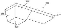
在一些变型中,插管附接设备可具有至少一个定位结构,该至少一个定位结构可例如有助于将插管相对于夹具部件中的一个或多个以一致的预定方式对准和定位。例如,如图2A所示,夹具部件中的至少一个可具有一个或多个突起(例如,夹具部件230上的表面252、254),该一个或多个突起成形为与设置在插管的一部分(例如,插管的附接部分)上的对应成形的凹部配合。例如,突起可为大体截头棱锥形(例如,四面倾斜结构),当将插管的近侧部分以特定的预定取向插入第一夹具部件和第二夹具部件之间的区域中时,该突起可被插入插管的近侧部分上的凹部中或以其他方式与其接合。一旦第一夹具部件220和第二夹具部件230围绕插管的部分闭合(例如,当可枢转的夹具部件处于闭合位置时),突起可坐置于设置在插管的部分上的凹部中。在一些变型中,夹具部件上的突起可具有深回拉成角度表面,当第一夹具部件和第二夹具部件已围绕插管的部分闭合时,该深回拉成角度表面阻止从第一夹具部件和第二夹具部件之间的区域中移除插管的部分。在其他变型中,定位结构可为双面斜坡,或者可具有形成三角形突起的两个倾斜表面,或者可具有任何合适的形状。与棱锥类似,双面斜坡可成形为与设置在插管的一部分上的对应成形的凹部(例如,三角形切口)接合。在另外的其他变型中,附加地或另选地,夹具部件中的一个或多个可包括至少一个定位结构,该至少一个定位结构为凹部,该凹部成形为与设置在插管的一部分上的突起接合。In some variations, the cannula attachment device may have at least one positioning feature that may, for example, assist in aligning and positioning the cannula relative to one or more of the clamp components in a consistent predetermined manner. For example, as shown in FIG. 2A, at least one of the clip members may have one or more protrusions (eg, surfaces 252, 254 on the clip member 230) that are shaped to interact with a portion disposed on the cannula Correspondingly shaped recesses on (eg, the attachment portion of the cannula) mate. For example, the protrusion may be a generally frusto-pyramidal shape (eg, a four-sided sloping structure) that is operative when the proximal portion of the cannula is inserted in the region between the first and second clamp members in a particular predetermined orientation. Can be inserted into or otherwise engaged with a recess on the proximal portion of the cannula. Once thefirst clamp member 220 and thesecond clamp member 230 are closed around the portion of the cannula (eg, when the pivotable clamp members are in the closed position), the protrusions may seat in recesses provided on the portion of the cannula. In some variations, the protrusion on the clip member may have a deep pullback angled surface that prevents the first clip from being pulled back from the first clip when the first clip member and the second clip member have closed around the portion of the cannula. The portion of the cannula removed in the region between the component and the second clamp component. In other variations, the locating structure may be a double-sided ramp, or may have two inclined surfaces forming a triangular protrusion, or may have any suitable shape. Similar to the pyramid, the double-sided ramp can be shaped to engage a correspondingly shaped recess (eg, a triangular cutout) provided on a portion of the cannula. In yet other variations, one or more of the clip components may additionally or alternatively include at least one locating feature that is a recess shaped to mate with a groove provided on a portion of the cannula. Protrusions engage.

在一些变型中,诸如上述,第一夹具部件可在打开位置和闭合位置之间移动或枢转,并且第二夹具部件可以是静止的或固定的。在这些变型中,定位结构(例如,棱锥、双面斜坡等)可位于第一可移动夹具部件上或第二固定夹具部件上。在其他变型中,第一夹具部件和第二夹具部件中的每一个都可具有定位结构,诸如倾斜表面、突起或凹部。在一些变型中,夹具部件中的一个可具有提供后视角的表面,该后视角防止插管的接纳在第一夹具部件和第二夹具部件之间的部分从第一夹具部件和第二夹具部件移除或脱开。In some variations, such as those described above, the first clamp member may be movable or pivotable between an open position and a closed position, and the second clamp member may be stationary or stationary. In these variations, the positioning structures (eg, pyramids, double-sided ramps, etc.) may be located on the first movable clamp part or the second fixed clamp part. In other variations, each of the first clamp member and the second clamp member may have locating structures, such as inclined surfaces, protrusions or recesses. In some variations, one of the clamp members may have a surface that provides a rear view that prevents the portion of the cannula received between the first and second clamp members from being removed from the first and second clamp members remove or disengage.

在一些变型中,附接设备还可在诸如插管的无菌部件和诸如第一夹具部件和第二夹具部件的非无菌部件(或外科系统的其他非无菌部件)之间提供无菌屏障。无菌屏障可例如由插置在插管与第一夹具部件和第二夹具部件之间的无菌适配器提供。In some variations, the attachment device may also provide sterility between sterile components, such as cannulas, and non-sterile components, such as the first and second clamp components (or other non-sterile components of the surgical system) barrier. The sterile barrier may be provided, for example, by a sterile adapter interposed between the cannula and the first and second clamp parts.

在一些变型中,附接设备可具有用于感测和/或识别套管针或插管的感测能力。例如,附接设备可具有传感器(例如,磁性传感器、电动传感器和/或光学传感器等),该传感器检测凸轮锁定机构的闩锁的位置,以便确定闩锁是否已闩锁到插管或套管针上。作为另一示例,附接设备可具有传感器,该传感器确定已插入到附接设备中的套管针或插管的类型。In some variations, the attachment device may have sensing capabilities for sensing and/or identifying the trocar or cannula. For example, the attachment device may have a sensor (eg, magnetic, electrodynamic, and/or optical, etc.) that detects the position of the latch of the cam locking mechanism in order to determine whether the latch is latched to the cannula or cannula on the needle. As another example, the attachment device may have a sensor that determines the type of trocar or cannula that has been inserted into the attachment device.

图2A至图6示出用于安装插管(诸如插管300)的具有两个夹具部件的附接设备的示例性变型。图2A至图2C示出附接设备200的不同视图。如图2A至图2C所示,附接设备200可具有第一夹具部件230,该第一夹具部件可围绕第一枢轴点234移动或枢转。第一夹具部件230可围绕第一枢轴点234在打开位置(诸如图2A至图2C和图4A至图4B所示)和闭合位置(诸如图5C和图6所示)之间枢转。附接设备200还可具有第二夹具部件220。在一些变型中,第二夹具部件220可以是固定的或静止的。在其他变型中,第二夹具部件220可类似于第一夹具部件枢转。第二夹具部件220可与第一夹具部件隔开,使得两个夹具部件220、230在它们之间限定某个区域,该区域被构造成接纳插管300的一部分(诸如例如,插管300的附接部分306)(参见图3)。两个夹具部件220、230可被支撑在支撑部件214上,该支撑部件诸如例如是机器人外科系统中的工具驱动器的板、棒、梁或其他合适的表面。第一夹具部件230可经由第一枢轴点234(例如,销接头、铰链等)在第一位置处支撑在支撑部件214上,并且第二夹具部件220可在与第一夹具部件230隔开的第二位置处支撑在支撑部件214上。在一些变型中,第一夹具部件230可附接到枢转结构,该枢转结构允许第一夹具部件230围绕枢轴点234旋转,并且该枢转结构可附接到支撑部件214。在此类变型中,第一夹具部件230可经由紧固件(例如,螺栓、钉子、螺钉、销等)或粘合剂(例如,环氧树脂、聚氨酯、聚酰亚胺等)和/或经由其他紧固技术(包括例如压接、焊接、铜焊等)附接到枢转结构。在其他变型中,第一夹具部件230可与诸如例如活动铰链的枢转结构一体形成。在一些变型中,第二夹具部件220可经由紧固件(例如,螺栓、钉子、螺钉、销等)、粘合剂(例如,环氧树脂、聚氨酯,聚酰亚胺等)和/或其他紧固技术(例如,压接、焊接、铜焊等)直接附接到支撑部件214。在其他变型中,第二夹具部件220可与支撑部件214一体形成。在一些变型中,两个夹具部件220、230可由塑料、金属或复合材料形成。在一些变型中,两个夹具部件220、230可经由机加工、模塑或其他制造技术形成。FIGS. 2A-6 show exemplary variations of an attachment device with two clamp components for installing a cannula, such ascannula 300 . 2A-2C show different views of theattachment device 200 . As shown in FIGS. 2A-2C , theattachment device 200 can have afirst clamp member 230 that can move or pivot about afirst pivot point 234 . Thefirst clamp member 230 is pivotable about afirst pivot point 234 between an open position (such as shown in FIGS. 2A-2C and 4A-4B ) and a closed position (such as shown in FIGS. 5C and 6 ). Theattachment device 200 may also have asecond clamp member 220 . In some variations, thesecond clamp member 220 may be stationary or stationary. In other variations, thesecond clamp member 220 may pivot similarly to the first clamp member. Thesecond clamp member 220 may be spaced apart from the first clamp member such that the twoclamp members 220, 230 define an area therebetween that is configured to receive a portion of the cannula 300 (such as, for example, a portion of the cannula 300). Attachment portion 306) (see Figure 3). The twogripper members 220, 230 may be supported on asupport member 214 such as, for example, a plate, rod, beam or other suitable surface of a tool driver in a robotic surgical system. Thefirst clamp member 230 may be supported on thesupport member 214 at a first location via a first pivot point 234 (eg, a pin joint, hinge, etc.), and thesecond clamp member 220 may be spaced from thefirst clamp member 230 . is supported on thesupport member 214 at the second position. In some variations, thefirst clamp member 230 may be attached to a pivot structure that allows thefirst clamp member 230 to rotate about thepivot point 234 , and the pivot structure may be attached to thesupport member 214 . In such variations, thefirst clamp member 230 may be via fasteners (eg, bolts, nails, screws, pins, etc.) or adhesives (eg, epoxy, polyurethane, polyimide, etc.) and/or Attachment to the pivoting structure is via other fastening techniques including, for example, crimping, welding, brazing, and the like. In other variations, thefirst clamp member 230 may be integrally formed with a pivoting structure such as, for example, a living hinge. In some variations, thesecond clamp member 220 may be via fasteners (eg, bolts, nails, screws, pins, etc.), adhesives (eg, epoxy, polyurethane, polyimide, etc.), and/or other Fastening techniques (eg, crimping, welding, brazing, etc.) are attached directly to thesupport member 214 . In other variations, thesecond clamp member 220 may be integrally formed with thesupport member 214 . In some variations, the twoclamp members 220, 230 may be formed from plastic, metal, or composite materials. In some variations, the twoclamp members 220, 230 may be formed via machining, molding, or other manufacturing techniques.

尽管图2A至图6所示的变型大体示出两个相对的夹具部件,但应当理解,在其他变型中,附接设备可包括多于两个的夹具部件。例如,至少两个夹具部件可能在同时平行地枢转以夹持到插管的第一侧上(例如,两个夹具部件类似于上述可枢转夹具部件230而移动),并且/或者至少两个夹具部件可被包括在内以夹持到插管的第二侧上(例如,两个叉状夹具部件类似于上述第二夹具部件220而固定)。在一些变型中,多于两个的夹具部件可在不同侧上与用于接纳插管的附接区域接界,并且当插管被接纳在附接区域中时,用户可分别致动每个夹具部件以使其围绕插管闭合。例如,两个夹具部件220、230可与用于接纳插管的附接区域的第一侧和第二侧接界,诸如图2A至图6所示,并且两个附加的夹具部件可与附接区域的第三侧和第四侧接界。用户可分别致动这两个附加的夹具部件以使其围绕插管闭合(例如,用户可将两个夹具部件220、230围绕插管夹持,并且然后将附加的夹具部件围绕插管夹持),或者可使用单个致动机构将两个附加的夹具部件与两个夹具部件220、230一起致动。在一些变型中,一个或多个外部夹具部件(或其他紧固机构)还可围绕一个或多个内部夹具部件设置,使得外部夹具部件可围绕内部夹具部件闭合以进一步确保内部夹具部件和插管之间的接合。Although the variations shown in FIGS. 2A-6 generally show two opposing clamp members, it should be understood that in other variations, the attachment device may include more than two clamp members. For example, at least two clamp members may pivot in parallel simultaneously to clamp to the first side of the cannula (eg, both clamp members move similar topivotable clamp members 230 described above), and/or at least two Two clamp members may be included to clamp to the second side of the cannula (eg, two fork clamp members are secured similar to thesecond clamp members 220 described above). In some variations, more than two clip components may interface on different sides with the attachment area for receiving the cannula, and when the cannula is received in the attachment area, the user may actuate each individually The clamp part is closed around the cannula. For example, twoclamp members 220, 230 may border the first and second sides of the attachment area for receiving the cannula, such as shown in FIGS. 2A-6, and two additional clamp members may be attached to the attachment area. The third and fourth sides of the contact area are bounded. The user may actuate the two additional clamp members separately to close them around the cannula (eg, the user may clamp the twoclamp members 220, 230 around the cannula, and then clamp the additional clamp members around the cannula) ), or a single actuation mechanism may be used to actuate the two additional clamp parts together with the twoclamp parts 220, 230. In some variations, one or more outer clamp members (or other securing mechanisms) may also be positioned around one or more inner clamp members, such that the outer clamp members can be closed around the inner clamp members to further secure the inner clamp members and the cannula connection between.

如图3所示,插管300可具有近侧部分302,诸如例如毂部、配件、连接器等。插管300的近侧部分302可包括附接部分306。附接部分306可从近侧部分302的一侧延伸。插管300还可具有轴304(在图3中部分地示出),该轴从近侧部分302延伸。轴304可具有管腔,可通过该管腔插入一个或多个外科器械。当插管300设置在患者中时,轴的远侧端部可位于患者的身体内,诸如例如体腔中。As shown in FIG. 3, thecannula 300 may have aproximal portion 302, such as, for example, a hub, a fitting, a connector, and the like. Theproximal portion 302 of thecannula 300 may include anattachment portion 306 . Theattachment portion 306 may extend from one side of theproximal portion 302 . Thecannula 300 may also have a shaft 304 (shown in part in FIG. 3 ) extending from theproximal portion 302 .Shaft 304 may have a lumen through which one or more surgical instruments may be inserted. When thecannula 300 is disposed in a patient, the distal end of the shaft may be located within the patient's body, such as, for example, in a body cavity.

附接设备200还可具有锁定部件240,诸如例如杆。锁定部件240可移动地联接到第一夹具部件230,并且被构造成围绕第二枢轴点244移动或枢转。如图2A至图2C所示,第二枢轴点244可设置在锁定部件240的两个端部之间。枢轴点244可被支撑在包括两个板246的结构上,这两个板联接到支撑部件214。两个板246可包括或可联接到螺栓、销或其他结构,该螺栓、销或其他结构装配到形成在锁定部件240中的一个或多个开口中。另选地,两个板246可包括开口,可通过该开口装配联接到锁定部件240的螺栓、销或其他结构。螺栓、销或其他结构和锁定部件240之间的接合可允许锁定部件240旋转或枢转。锁定部件240可围绕第二枢轴点244在解锁位置(如图2A至图2C和图4A至图4B所示)和锁定偏心位置(如图5C和图6所示)之间枢转。当锁定部件240处于解锁位置时,第一夹具部件230处于打开位置,并且当锁定部件240处于锁定偏心位置时,第一夹具部件230处于闭合位置。Theattachment device 200 may also have a lockingmember 240, such as, for example, a lever. The lockingmember 240 is movably coupled to thefirst clamp member 230 and is configured to move or pivot about asecond pivot point 244 . As shown in FIGS. 2A to 2C , asecond pivot point 244 may be provided between the two ends of the lockingmember 240 . Thepivot point 244 may be supported on a structure that includes twoplates 246 that are coupled to thesupport member 214 . The twoplates 246 may include or may be coupled to bolts, pins or other structures that fit into one or more openings formed in the lockingmember 240 . Alternatively, the twoplates 246 may include openings through which bolts, pins or other structures coupled to the lockingmember 240 may be fitted. The engagement between the bolt, pin or other structure and the lockingmember 240 may allow the lockingmember 240 to rotate or pivot. The lockingmember 240 is pivotable about asecond pivot point 244 between an unlocked position (shown in FIGS. 2A-2C and 4A-4B ) and a locked off-center position (shown in FIGS. 5C and 6 ). When the lockingmember 240 is in the unlocked position, thefirst clamp member 230 is in the open position, and when the lockingmember 240 is in the locking eccentric position, thefirst clamp member 230 is in the closed position.

附接设备200可包括至少一个锁定特征或定位结构,该至少一个锁定特征或定位结构被构造成与设置在插管300的一部分(诸如例如,插管300的附接部分306)上的对应结构配合。在一些变型中,定位结构可设置在第一夹具部件230上。附加地或另选地,定位结构可至少部分地设置在第二夹具部件220上,或者邻近或包围两个夹具部件220、230之间的区域的另一部件或表面上。在图2A所示的变型中,定位结构位于第一夹具部件230上并且可由两个表面252、254形成。两个表面252、254可以是形成三角形突起或双面斜坡的锥形表面。如图2A所示,两个表面252、254相对于第一夹具部件230的纵向轴线成角度。当附接部分306被接纳在两个夹具部件220、230之间的区域中并且第一夹具部件处于其闭合位置时(如图5C和图6所示),由两个表面252、254形成的三角形突起可能能够闩锁到插管300的附接部分306中。附接部分306可具有两个表面308、310(参见图3),这两个表面形成被构造成与由两个表面252、254形成的三角形突起配合的形状或结构。在一些变型中,定位结构可包括附加的成角度表面或锥形表面并呈现不同的形状(例如,截头棱锥形形状,如下面参考图9A和图9B进一步描述的)。Attachment device 200 may include at least one locking feature or locating feature configured to correspond to a feature provided on a portion ofcannula 300 such as, for example,attachment portion 306 ofcannula 300 Cooperate. In some variations, locating structures may be provided on thefirst clamp member 230 . Additionally or alternatively, the locating structure may be provided at least partially on thesecond clamp member 220 or on another member or surface adjacent to or surrounding the area between the twoclamp members 220 , 230 . In the variant shown in FIG. 2A , the positioning structure is located on thefirst clamp part 230 and can be formed by twosurfaces 252 , 254 . The twosurfaces 252, 254 may be tapered surfaces forming triangular protrusions or double-sided ramps. As shown in FIG. 2A , the twosurfaces 252 , 254 are angled relative to the longitudinal axis of thefirst clamp member 230 . When theattachment portion 306 is received in the area between the twoclamp members 220, 230 and the first clamp member is in its closed position (as shown in Figures 5C and 6), the surface formed by the twosurfaces 252, 254 The triangular protrusions may be capable of latching into theattachment portion 306 of thecannula 300 . Theattachment portion 306 may have twosurfaces 308 , 310 (see FIG. 3 ) that form a shape or structure configured to mate with the triangular protrusions formed by the twosurfaces 252 , 254 . In some variations, the positioning structures may include additional angled surfaces or tapered surfaces and assume different shapes (eg, frusto-pyramid shapes, as further described below with reference to FIGS. 9A and 9B ).

在一些方面,两个夹具部件220、230可以是非无菌的,并且插管300可以是无菌的。因此,可提供无菌屏障,其将非无菌夹具部件220、230与无菌插管300分开。如图3所示,无菌适配器212可在非无菌夹具部件220、230和无菌插管300之间形成无菌屏障。无菌适配器212可为盖,该盖具有开口211(参见图2C和图3),用于接纳插管300的附接部分306,使得附接部分306在被接纳到无菌适配器212中时被无菌适配器212覆盖或包围。无菌适配器212可以是充分柔性的,使得其可变形(例如,当通过开口211插入附接部分306时接纳附接部分306),但具有足够的刚度,使得其保持未变形的或静止的形状,该未变形的或静止的形状大体对应于插管300的附接部分306的形状。具体地,在其未变形状态下,无菌适配器212可形成具有两个锥形表面202、204的形状,该形状基本上对应于由附接部分306的两个锥形表面308、310形成的形状。In some aspects, the twoclip components 220, 230 may be non-sterile, and thecannula 300 may be sterile. Thus, a sterile barrier may be provided that separates thenon-sterile clip components 220, 230 from thesterile cannula 300. As shown in FIG. 3 , thesterile adapter 212 may form a sterile barrier between thenon-sterile clamp components 220 , 230 and thesterile cannula 300 . Thesterile adapter 212 may be a cap having an opening 211 (see FIGS. 2C and 3 ) for receiving theattachment portion 306 of thecannula 300 such that theattachment portion 306 when received into thesterile adapter 212 is Thesterile adapter 212 covers or encloses.Sterile adapter 212 may be sufficiently flexible so that it is deformable (eg, to receiveattachment portion 306 when inserted through opening 211 ), but sufficiently rigid so that it maintains an undeformed or resting shape , the undeformed or resting shape generally corresponds to the shape of theattachment portion 306 of thecannula 300 . Specifically, in its undeformed state, thesterile adapter 212 may be formed into a shape having two taperedsurfaces 202 , 204 substantially corresponding to the shape formed by the twotapered surfaces 308 , 310 of theattachment portion 306 . shape.

无菌适配器212可被安装到支撑部件210(诸如例如,杆或梁)并由其支撑。如图3所示,支撑部件210可包括一个或多个接合机构216,该一个或多个接合机构被构造成将支撑部件210可释放地联接或附接到支撑部件214(如上所述)。例如,接合机构216可包括闩锁,该闩锁闩锁到支撑部件214的边缘或脊218上。附加地或另选地,接合机构216可包括钩、螺钉、销和/或能够将支撑部件210联接到支撑部件214的其他机构。在一些方面,附加地或另选地,可使用粘合剂来将支撑部件210联接到支撑部件214。当支撑部件210附接到支撑部件214时,无菌适配器212可设置在两个夹具部件220、230之间的区域中,如图2A至图2C和图4A至图6所示。Sterile adapter 212 may be mounted to and supported by support member 210 (such as, for example, a rod or beam). As shown in FIG. 3 , thesupport member 210 may include one ormore engagement mechanisms 216 configured to releasably couple or attach thesupport member 210 to the support member 214 (as described above). For example, theengagement mechanism 216 may include a latch that latches onto the edge orridge 218 of thesupport member 214 . Additionally or alternatively, theengagement mechanism 216 may include hooks, screws, pins, and/or other mechanisms capable of coupling thesupport member 210 to thesupport member 214 . In some aspects, an adhesive may additionally or alternatively be used to couple thesupport member 210 to thesupport member 214 . When thesupport member 210 is attached to thesupport member 214, thesterile adapter 212 may be disposed in the area between the twoclamp members 220, 230, as shown in FIGS. 2A-2C and 4A-6.

图4A至图5C示出在插管附接或联接操作期间处于不同构型的附接设备200。如图4A所示,锁定部件240被定位在解锁位置,并且第一夹具部件230被定位在打开位置。插管300可沿方向410移动,使得插管300的附接部分306被插入两个夹具部件220、230之间的区域中,或者更具体地,通过开口211插入无菌适配器212中,该无菌适配器位于两个夹具部件220、230之间的区域中。在一些变型中,第一夹具部件230的表面254可被构造成有助于当将附接部分306插入两个夹具部件220、230之间的区域中时对该附接部件进行引导和取向。例如,表面254可成角度,使得当将附接部分306以图4A所示的预定取向(例如,以其中表面308、310面向表面252、254并且被构造成与表面252、254接合或配合的取向,如图5C所示)插入两个夹具部件220、230之间的区域中时,该表面平滑地接纳附接部分306。并且当将附接部分306以不同的取向插入两个夹具部件220、230之间的区域中时,表面254可推压或以其他方式干涉附接部分306,以指示附接部分306未相对于两个夹具部件220、230正确地取向。例如,当附接部分306未以预定取向插入两个夹具部件220、230之间的区域中时,第一表面254可防止附接部分306被插入两个夹具部件220、230之间的区域中(例如,通过产生对于附接部分306而言太小而无法插入该区域中的间隙)。附加地或另选地,当附接部分306未以预定取向插入区域中时,第一表面254可针对附接部分306施加向后的力(经由第一表面254和附接部分306之间的干涉),这可能会向用户发出信号,表明附接部分306未相对于两个夹具部件220、230正确地取向。在一些变型中,为了帮助将附接部分306引导到两个夹具部件220、230之间的区域中,当第一夹具部件230处于打开位置时,第一表面254可成角度以大体上对应于附接部分306的表面312的角度。因此,随着附接部分306被插入两个夹具部件220、230之间的区域中,第一表面254可接触表面312并且帮助将附接部分306引导到两个夹具部件220、230之间的区域中。4A-5C illustrate theattachment device 200 in different configurations during a cannula attachment or coupling operation. As shown in FIG. 4A, the lockingmember 240 is positioned in the unlocked position, and thefirst clamp member 230 is positioned in the open position. Thecannula 300 is moveable indirection 410 such that theattachment portion 306 of thecannula 300 is inserted into the area between the twoclamp members 220, 230 or, more specifically, into thesterile adapter 212 through theopening 211, which is free of The bacterial adapter is located in the area between the twoclamp parts 220 , 230 . In some variations, thesurface 254 of thefirst clamp member 230 may be configured to assist in guiding and orienting theattachment portion 306 when theattachment portion 306 is inserted into the area between the twoclamp members 220 , 230 . For example, thesurface 254 may be angled such that when theattachment portion 306 is oriented in the predetermined orientation shown in FIG. oriented, as shown in FIG. 5C ), the surface smoothly receives theattachment portion 306 when inserted into the area between the twoclamp members 220 , 230 . And when theattachment portion 306 is inserted into the area between the twoclamp members 220, 230 in different orientations, thesurface 254 may push against or otherwise interfere with theattachment portion 306 to indicate that theattachment portion 306 is not relative to theattachment portion 306. The twoclamp parts 220, 230 are correctly oriented. For example, thefirst surface 254 may prevent theattachment portion 306 from being inserted into the region between the twoclip members 220, 230 when theattachment portion 306 is not inserted into the region between the twoclip members 220, 230 in the predetermined orientation (eg, by creating a gap that is too small for theattachment portion 306 to fit into this area). Additionally or alternatively, when theattachment portion 306 is not inserted into the region in the predetermined orientation, thefirst surface 254 may apply a rearward force against the attachment portion 306 (via the contact between thefirst surface 254 and the attachment portion 306 ). interference), which may signal to the user that theattachment portion 306 is not properly oriented relative to the twoclamp members 220, 230. In some variations, to help guide theattachment portion 306 into the area between the twoclamp members 220, 230, when thefirst clamp member 230 is in the open position, thefirst surface 254 may be angled to substantially correspond to The angle of thesurface 312 of theattachment portion 306 . Thus, as theattachment portion 306 is inserted into the area between the twoclamp members 220 , 230 , thefirst surface 254 may contact thesurface 312 and help guide theattachment portion 306 into the area between the twoclamp members 220 , 230 . in the area.

在一些变型中,第二夹具部件220可具有成角度表面或锥形表面,该表面可将附接部分306以预定取向引导到两个夹具部件220、230之间的区域中。如图4A所示,第二夹具部件220可具有成角度表面206,该成角度表面成形为对应于附接部分306的底表面314。成角度表面206可朝向第一夹具部件230轻微成角度,使得其在两个夹具部件220、230之间的区域中形成轻微的锥度。因此,当将附接部分306插入两个夹具部件220、230之间的区域中时,第二夹具部件220可接触附接部分306并有助于将其引导到该区域中。In some variations, thesecond clamp member 220 may have an angled or tapered surface that may guide theattachment portion 306 into the area between the twoclamp members 220, 230 in a predetermined orientation. As shown in FIG. 4A , thesecond clamp member 220 may have anangled surface 206 that is shaped to correspond to thebottom surface 314 of theattachment portion 306 . Theangled surface 206 may be slightly angled towards thefirst clamp part 230 such that it tapers slightly in the area between the twoclamp parts 220 , 230 . Thus, when theattachment portion 306 is inserted into the area between the twoclamp members 220, 230, thesecond clamp member 220 can contact theattachment portion 306 and help guide it into the area.

在将附接部分306插入两个夹具部件220、230之间的区域中之后,通过沿方向420枢转锁定部件240可使锁定部件240从其解锁位置移动到其锁定偏心位置,如图4B所示。图5A至图5C示出随着锁定部件240从其解锁位置枢转到其锁偏心位置,处于不同构型的锁定部件。在所示变型中,第一夹具部件230可具有沿着其主体的纵向长度形成的狭槽232。狭槽232可沿着第一夹具部件230的部分长度延伸。锁定部件240可具有可沿着狭槽232的长度移动的第一端部250。具体地,锁定部件240可具有位于其第一端部250处的销钉,该销钉设置在狭槽232中并且可沿着该狭槽的长度移动。锁定部件240可具有形状类似柄部或旋钮的第二端部242。锁定部件240可具有轴248,该轴从锁定部件240的第二端部242穿过第二枢轴点244延伸到锁定部件240的第一端部250。锁定部件240的第二端部242可例如由用户移动,以使锁定部件240在解锁位置和锁定偏心位置之间枢转。例如,用户可施加力420(如图4B所示)来移动锁定部件240的第二端部242,以便将锁定部件240从解锁位置枢转到锁定偏心位置。用户可通过按压或推动锁定部件240的第二端部242来施加力420。After insertion of theattachment portion 306 into the area between the twoclamp members 220, 230, the lockingmember 240 may be moved from its unlocked position to its locked off-center position by pivoting the lockingmember 240 indirection 420, as shown in Figure 4B Show. 5A-5C illustrate the locking member in different configurations as the lockingmember 240 pivots from its unlocked position to its lock off-center position. In the variation shown, thefirst clamp member 230 may have aslot 232 formed along the longitudinal length of its body. Theslot 232 may extend along a portion of the length of thefirst clamp member 230 . The lockingmember 240 may have afirst end 250 movable along the length of theslot 232 . Specifically, lockingmember 240 may have a pin at itsfirst end 250 that is disposed inslot 232 and that is movable along the length of the slot. The lockingmember 240 may have asecond end 242 shaped like a handle or knob. The lockingmember 240 may have ashaft 248 extending from thesecond end 242 of the lockingmember 240 through thesecond pivot point 244 to thefirst end 250 of the lockingmember 240 . Thesecond end 242 of the lockingmember 240 can be moved, eg, by a user, to pivot the lockingmember 240 between an unlocked position and a locked off-center position. For example, a user may apply force 420 (shown in FIG. 4B ) to move thesecond end 242 of the lockingmember 240 in order to pivot the lockingmember 240 from the unlocked position to the locked off-center position. The user may apply theforce 420 by pressing or pushing on thesecond end 242 of the lockingmember 240 .

在图5A中,锁定部件240的第一端部250已沿着第一夹具部件230的狭槽232在第一方向上移动了第一距离。随着锁定部件240继续枢转,锁定部件240的第一端部250可继续沿着狭槽232在第一方向上移动到死点位置,如图5B所示。在死点位置,锁定部件240的轴248(包括部分248a、248b)可沿着轴线430对准。在图5B所示的示例中,一旦锁定部件240已枢转到死点位置,锁定部件240就已将第一夹具部件230大致运动到闭合位置,并且锁定部件240进一步移动超过死点位置不会导致第一夹具部件230另外明显运动。尽管当锁定部件240已枢转到死点位置时,第一夹具部件230在图5B中示出为大致处于闭合位置,但在其他变型中,第一夹具部件230可处于从闭合位置偏离的位置。在一些变型中,第一夹具部件230可由可压缩材料形成,随着锁定部件240枢转超过死点位置,该可压缩材料开始和/或继续变形。在一些变型中,当锁定部件240处于死点位置时,其可在适当的位置平衡。例如,如果用户施加刚刚好的力来将锁定部件240移动到死点位置中并且未施加附加的力将锁定部件240移动超过死点位置,则锁定部件240可在死点位置保持平衡。In FIG. 5A , thefirst end 250 of the lockingmember 240 has moved a first distance in the first direction along theslot 232 of thefirst clamp member 230 . As the lockingmember 240 continues to pivot, thefirst end 250 of the lockingmember 240 may continue to move in the first direction along theslot 232 to the dead center position, as shown in Figure 5B. At the dead center position, theshaft 248 of the locking member 240 (including theportions 248a, 248b ) can be aligned along theaxis 430 . In the example shown in Figure 5B, once the lockingmember 240 has pivoted to the dead center position, the lockingmember 240 has moved thefirst clamp member 230 substantially to the closed position, and further movement of the lockingmember 240 beyond the dead center position will not This results in additional significant movement of thefirst clamp member 230 . Although thefirst clamp member 230 is shown in FIG. 5B as being generally in the closed position when the lockingmember 240 has pivoted to the dead center position, in other variations thefirst clamp member 230 may be in a position offset from the closed position . In some variations, thefirst clamp member 230 may be formed of a compressible material that begins and/or continues to deform as the lockingmember 240 pivots past the dead center position. In some variations, the lockingmember 240 may be balanced in place when it is in the dead center position. For example, if the user applies just enough force to move lockingmember 240 into the dead center position and no additional force is applied to move lockingmember 240 beyond the dead center position, lockingmember 240 may remain balanced at the dead center position.

当沿方向420在锁定部件240上施加附加的力时,锁定部件240可枢转直到其处于锁定偏心位置,如图5C所示。一旦锁定部件240枢转超过死点位置(例如,如图5C所示),则偏置力可作用在锁定部件240上并迫使其继续枢转,直到锁定部件240处于锁定偏心位置。偏置力作用在锁定部件240上,将锁定部件240保持在锁定偏心位置,直到足够的反作用力克服了偏置力来将锁定部件240移回到其初始解锁位置。因此,用户必须克服作用在锁定部件240上的附加的偏置力,然后用户才能将锁定部件240移回到其解锁位置并打开第一夹具部件230。在锁定偏心位置中,锁定部件240的第一端部250可设置在狭槽232的远端处(例如,与狭槽的更靠近枢轴点234的端部相对的端部),并且第一夹具部件230可处于闭合位置。因此,通过将锁定部件240从解锁位置移动或枢转到锁定偏心位置,用户可将第一夹具部件230枢转到闭合位置中。When additional force is exerted on lockingmember 240 indirection 420, lockingmember 240 can pivot until it is in the locking off-center position, as shown in Figure 5C. Once lockingmember 240 has pivoted past the dead center position (eg, as shown in FIG. 5C ), a biasing force may act on lockingmember 240 and force it to continue pivoting until lockingmember 240 is in the locking off-center position. The biasing force acts on the lockingmember 240, maintaining the lockingmember 240 in the locking off-center position until sufficient reaction force overcomes the biasing force to move the lockingmember 240 back to its initial unlocked position. Therefore, the user must overcome the additional biasing force acting on the lockingmember 240 before the user can move the lockingmember 240 back to its unlocked position and open thefirst clamp member 230 . In the locking eccentric position, thefirst end 250 of the lockingmember 240 may be disposed at the distal end of the slot 232 (eg, the end opposite the end of the slot that is closer to the pivot point 234), and the first Theclamp member 230 may be in a closed position. Thus, by moving or pivoting the lockingmember 240 from the unlocked position to the locking off-center position, the user can pivot thefirst clamp member 230 into the closed position.

当第一夹具部件230处于闭合位置时,两个夹具部件220、230可将插管300的附接部分306保持在两个夹具部件220、230之间的区域中。在一些变型中,锁定部件240用于防止插管300从附接设备200脱开或脱离。例如,如图6所示,当锁定部件240处于锁定偏心位置并且插管300保持在两个夹具部件220、230之间时,沿方向502施加的拉力产生沿方向504向上推动的力,这用于使锁定部件240沿方向506枢转,从而进一步将锁定部件240推向锁定偏心位置。该拉力可由诸如例如在外科操作或规程期间施加到插管300的一部分(例如,近侧部分302或轴304)的力引起。如上所述,第一夹具部件可具有被构造成与附接部分306的表面310配合并接合的表面252。因此,当沿方向502拉动插管300时,表面252可与表面310接合,这产生沿方向504的力。然后,沿方向504的力作用在轴248的第二部分248b上,以使锁定部件240沿方向506枢转。When thefirst clamp part 230 is in the closed position, the twoclamp parts 220 , 230 can hold theattachment portion 306 of thecannula 300 in the area between the twoclamp parts 220 , 230 . In some variations, thelocking feature 240 is used to prevent thecannula 300 from being detached or disengaged from theattachment device 200 . For example, as shown in FIG. 6, when the lockingmember 240 is in the locking eccentric position and thecannula 300 is held between the twoclamp members 220, 230, a pulling force applied in thedirection 502 produces an upwardly pushing force in thedirection 504, which uses The purpose is to pivot the lockingmember 240 in thedirection 506, thereby further pushing the lockingmember 240 towards the locking eccentric position. The pulling force may be caused by a force applied to a portion of cannula 300 (eg,proximal portion 302 or shaft 304 ), such as, for example, during a surgical operation or procedure. As described above, the first clamp member may have asurface 252 that is configured to mate with and engage thesurface 310 of theattachment portion 306 . Thus, whencannula 300 is pulled indirection 502 ,surface 252 may engagesurface 310 , which creates a force indirection 504 . A force indirection 504 then acts onsecond portion 248b ofshaft 248 to pivot lockingmember 240 indirection 506 .

图16为使用诸如附接设备200或本文所述的其他附接设备的附接设备将插管附接到外科系统的方法1900的示例性变型的流程图。方法1900可任选地包括在1902处将附接装置的锁定部件(例如,锁定部件240)定位在解锁位置。锁定部件可操作地联接到夹具部件(例如,第一夹具部件230)并且被构造成使夹具部件在打开位置和闭合位置之间枢转。当锁定部件被定位在解锁位置时,锁定部件可使夹具部件枢转到打开位置。在打开位置,夹具部件可允许插管的一部分(例如,插管300的附接部分306)被接纳在夹具部件和另一夹具部件(例如,第二夹具部件220)之间的区域中。因此,当锁定部件不处于解锁位置并且夹具部件不处于打开位置时,在1902处,可将锁定部件移动到解锁位置中以便将夹具部件定位在打开位置。当锁定部件已处于解锁位置并且夹具部件处于打开位置时,可省略步骤1902。16 is a flowchart of an exemplary variation of amethod 1900 of attaching a cannula to a surgical system using an attachment device such asattachment device 200 or other attachment devices described herein. Themethod 1900 can optionally include, at 1902, positioning a locking member (eg, locking member 240) of the attachment device in an unlocked position. The locking member is operably coupled to the clamp member (eg, the first clamp member 230) and is configured to pivot the clamp member between an open position and a closed position. When the locking member is positioned in the unlocked position, the locking member may pivot the clamp member to the open position. In the open position, the clamp member may allow a portion of the cannula (eg, theattachment portion 306 of the cannula 300 ) to be received in an area between the clamp member and another clamp member (eg, the second clamp member 220 ). Thus, when the locking member is not in the unlocked position and the clamp member is not in the open position, at 1902 the locking member can be moved into the unlocked position to position the clamp member in the open position.Step 1902 may be omitted when the locking member is already in the unlocked position and the clamp member is in the open position.

在1904处,可将插管的部分(例如,插管300的附接部分306)插入两个夹具部件(例如,两个夹具部件220、230)之间的区域中。在1906处,可将插管相对于两个夹具部件以预定取向定位。当插管相对于两个夹具部件处于预定取向时,在插管完全插入两个夹具部件之间的区域中之后,设置在两个夹具部件中的至少一个上的定位结构(例如,由两个表面252、254限定的定位结构)可与设置在插管的部分(例如,表面308、310)上的对应结构配合。在1908处,可将锁定部件从解锁位置移动到锁定偏心位置,以便将夹具部件枢转到闭合位置。当夹具部件处于闭合位置时,两个夹具部件可将插管的部分保持在两个夹具部件之间的区域中。例如,两个夹具部件可围绕插管的部分夹持,使得插管的部分被保持或固定在两个夹具部件之间的区域中。设置在两个夹具部件中的一个上或者邻近两个夹具部件之间的区域的另一表面上的定位结构或某个其他结构可闩锁到设置在插管的部分上的对应结构中,以将插管的部分保持在两个夹具部件之间的区域中。At 1904, a portion of the cannula (eg, theattachment portion 306 of the cannula 300) can be inserted into the area between the two clamp members (eg, the twoclamp members 220, 230). At 1906, the cannula can be positioned in a predetermined orientation relative to the two clamp components. When the cannula is in a predetermined orientation relative to the two clamp parts, after the cannula is fully inserted into the area between the two clamp parts, a positioning structure (eg, formed by two clamp parts) provided on at least one of the two clamp parts The positioning structures defined bysurfaces 252, 254) may cooperate with corresponding structures provided on portions of the cannula (eg, surfaces 308, 310). At 1908, the locking member can be moved from the unlocked position to the locking off-center position in order to pivot the clamp member to the closed position. When the clamp parts are in the closed position, the two clamp parts can hold the portion of the cannula in the area between the two clamp parts. For example, the two clamp parts can be clamped around the portion of the cannula such that the portion of the cannula is held or fixed in the area between the two clamp parts. A locating structure or some other structure provided on one of the two clamp parts or on the other surface adjacent to the area between the two clamp parts can be latched into a corresponding structure provided on the part of the cannula to A portion of the cannula is held in the area between the two clamp parts.

图7A和图7B示出用于安装插管(诸如插管680)的具有两个夹具部件的附接设备的另一示例性变型。图7A和图7B示出处于两种不同构型的附接设备600。具体地,图7A示出处于第一构型的附接设备600,其中附接设备600的夹具部件630处于打开位置,并且图7B示出处于第二构型的附接设备600,其中夹具部件630处于闭合位置。附接设备600的结构和/或功能可类似于本文描述的一个或多个其他附接设备,包括参考图2A至图6所描述的附接设备200,其变型包括例如:(1)定位结构位于固定夹具部件而不是可移动夹具部件上;以及(2)可移动夹具部件630可沿方向652移动或平移,而不是可枢转。如图7A所示,附接设备600可包括夹具部件630和附加的夹具部件620。两个夹具部件620、630可在它们之间限定某个区域,在该区域中可接纳插管680的附接部分686。7A and 7B illustrate another exemplary variation of an attachment device with two clamp components for mounting a cannula, such ascannula 680 . 7A and 7B illustrateattachment device 600 in two different configurations. Specifically, FIG. 7A shows theattachment apparatus 600 in a first configuration with theclamp member 630 of theattachment apparatus 600 in an open position, and FIG. 7B shows theattachment apparatus 600 in a second configuration with theclamp member 630 is in the closed position.Attachment device 600 may be similar in structure and/or function to one or more other attachment devices described herein, includingattachment device 200 described with reference to FIGS. 2A-6, with variations including, for example: (1) Positioning structures on a fixed clamp member rather than a movable clamp member; and (2) themovable clamp member 630 can move or translate indirection 652, rather than pivotable. As shown in FIG. 7A , theattachment device 600 may include aclamp member 630 and anadditional clamp member 620 . The twoclamp members 620, 630 may define an area therebetween in which theattachment portion 686 of thecannula 680 may be received.

插管680的结构和/或功能可类似于本文所述的一个或多个其他插管变型,包括参考图3至图6所描述的插管300。例如,插管680可包括近侧部分682和轴684。轴684可具有管腔,可通过该管腔插入外科器械690。外科器械690可包括孔口692,可通过该孔口将流体引入患者身体中和/或从患者体内移除。流入和/或流出孔口692的流体的流动可由阀控制器694控制。插管680的近侧部分682可包括附接部分686。The structure and/or function of thecannula 680 may be similar to one or more of the other cannula variations described herein, including thecannula 300 described with reference to FIGS. 3-6 . For example,cannula 680 may includeproximal portion 682 andshaft 684 .Shaft 684 may have a lumen through whichsurgical instrument 690 may be inserted.Surgical instrument 690 may include anaperture 692 through which fluid may be introduced into and/or removed from a patient's body. The flow of fluid into and/or out of theorifice 692 may be controlled by thevalve controller 694 .Proximal portion 682 ofcannula 680 may includeattachment portion 686 .

附接设备600还可包括锁定部件640(例如,杆、棒、梁或类似结构),该锁定部件被构造成围绕枢轴点644枢转。锁定部件640可经由销钉650(或其他结构)操作地联接到夹具部件630,该销钉装配到形成在夹具部件630中的狭槽632中。销钉650可被构造成沿着狭槽632的长度移动。与附接设备200类似,锁定部件640可被构造成使夹具部件630在打开位置和闭合位置之间移动。当锁定部件处于第一解锁位置时,夹具部件630可处于打开位置(如图7A所示),并且当锁定部件处于第二锁定偏心位置时,夹具部件630可处于闭合位置(如图7B所示)。锁定部件640可包括柄部642,该柄部设置在与联接到夹具部件630的端部相对的端部处。当锁定部件640枢转到其锁定偏心位置时,夹具部件630可沿方向652(如图7A所示)移动到其锁定位置。Theattachment device 600 may also include a locking member 640 (eg, rod, rod, beam, or similar structure) configured to pivot about apivot point 644 . The lockingmember 640 may be operatively coupled to theclamp member 630 via a pin 650 (or other structure) that fits into aslot 632 formed in theclamp member 630 . Thepin 650 may be configured to move along the length of theslot 632 . Similar toattachment device 200, lockingmember 640 may be configured to moveclamp member 630 between an open position and a closed position. When the locking member is in the first unlocked position, theclamp member 630 may be in an open position (as shown in FIG. 7A ), and when the locking member is in the second locking off-center position, theclamp member 630 may be in a closed position (as shown in FIG. 7B ) ). The lockingmember 640 may include ahandle 642 disposed at an end opposite the end coupled to theclamp member 630 . When the lockingmember 640 is pivoted to its locking off-center position, theclamp member 630 can move in direction 652 (shown in FIG. 7A ) to its locking position.

当锁定部件640处于锁定偏心位置时,插管680的附接部分686可被保持在两个夹具部件620、630之间的区域中,如图7B所示。与附接设备200类似,锁定部件640的偏心锁定布置减小了锁定部件640可能不经意地从其锁定偏心位置枢转到其解锁位置的风险。当锁定部件640处于锁定偏心位置时,锁定部件640可被朝向锁定偏心位置偏置,使得必须先克服偏置力,然后锁定部件640才能枢转回到其解锁位置。该偏置力由锁定部件640的偏心布置产生,类似于上述附接设备200的锁定部件240的偏心布置。锁定部件640和两个夹具部件620、630可被支撑在支撑件(未示出)上。锁定部件640可经由枢轴点644可移动地支撑在支撑件上;夹具部件620可固定地支撑在支撑件上;并且夹具部件630可经由第二枢轴点或轨道(未示出)可移动地支撑在支撑件上,该第二枢轴点或轨道允许夹具部件630相对于支撑件移动。When the lockingmember 640 is in the locking eccentric position, theattachment portion 686 of thecannula 680 may be retained in the area between the twoclamp members 620, 630, as shown in Figure 7B. Similar toattachment device 200, the off-center locking arrangement of lockingmember 640 reduces the risk that lockingmember 640 may inadvertently pivot from its locked off-center position to its unlocked position. When the lockingmember 640 is in the locking off-center position, the lockingmember 640 may be biased towards the locking off-center position such that the biasing force must be overcome before the lockingmember 640 can pivot back to its unlocked position. This biasing force is created by the eccentric arrangement of the lockingmembers 640, similar to the eccentric arrangement of the lockingmembers 240 of theattachment device 200 described above. The lockingpart 640 and the twoclamp parts 620, 630 may be supported on supports (not shown). The lockingmember 640 may be movably supported on the support via apivot point 644; theclamp member 620 may be fixedly supported on the support; and theclamp member 630 may be movable via a second pivot point or track (not shown) Supported on the support, this second pivot point or track allows theclamp member 630 to move relative to the support.

附接设备600可具有定位结构,该定位结构被构造成与设置在插管680的附接部分686上的对应结构配合。在图7A和图7B所示的变型中,定位结构可以是设置在固定夹具部件620上的突起622。在其他变型中,诸如图2A至图6所描绘的变型,定位结构可设置在可移动夹具部件上。附加地或另选地,一个或多个定位结构可设置在一个或两个夹具部件620、630上、或者邻近两个夹具部件620、630之间的区域的另一部件或表面上。突起622可具有多个锥形表面或成角度表面。突起622可被构造成装配到形成在插管680的附接部分686中的凹部688中并与其配合。当夹具部件630处于闭合位置(如图7B所示)并且突起622已与凹部688配合时,突起622可防止插管680从附接设备600移除或脱开。例如,突起622可具有带有深回拉角度的成角度表面623,该深回拉角度防止插管680的附接部分686被拉出两个夹具部件620、630之间的区域。夹具部件630可具有相对于夹具部件630的纵向轴线轻微成角度(例如,5度角)的表面631。当夹具部件630处于闭合位置时,成角度表面631可向下夹持在附接部分686的表面689上,该表面可成角度以对应于表面631的角度。成角度表面631和对应成角的表面689还可有助于将附接部分686保持在两个夹具部件620、630之间的区域中。Theattachment device 600 may have locating structures configured to cooperate with corresponding structures provided on theattachment portion 686 of thecannula 680 . In the variant shown in FIGS. 7A and 7B , the positioning structure may be aprotrusion 622 provided on the fixingclamp part 620 . In other variations, such as those depicted in Figures 2A-6, the positioning structure may be provided on the movable clamp member. Additionally or alternatively, one or more locating structures may be provided on one or bothclamp members 620 , 630 , or on another member or surface adjacent to the area between the twoclamp members 620 , 630 . Theprotrusions 622 may have multiple tapered or angled surfaces. Theprotrusions 622 may be configured to fit into and mate withrecesses 688 formed in theattachment portion 686 of thecannula 680 . Theprotrusions 622 may prevent thecannula 680 from being removed or disengaged from theattachment device 600 when theclamp member 630 is in the closed position (shown in FIG. 7B ) and theprotrusions 622 have engaged with therecesses 688 . For example, theprotrusion 622 may have anangled surface 623 with a deep pullback angle that prevents theattachment portion 686 of thecannula 680 from being pulled out of the area between the twoclamp members 620 , 630 . Theclamp member 630 may have asurface 631 that is slightly angled (eg, a 5 degree angle) relative to the longitudinal axis of theclamp member 630 . When theclamp member 630 is in the closed position, theangled surface 631 can clamp down on thesurface 689 of theattachment portion 686 , which can be angled to correspond to the angle of thesurface 631 . Theangled surface 631 and correspondingangled surface 689 may also help retain theattachment portion 686 in the area between the two clamp members 620,630.

与插管附接设备200的定位结构类似,突起622可能能够将附接部分686相对于两个夹具部件620、630以预定取向引导到两个夹具部件620、630之间的区域中。例如,突起622可具有成角度表面624,该成角度表面帮助用户确定附接部分686是否相对于两个夹具部件620、630以预定取向接纳在两个夹具部件620、630之间的区域中。成角度表面624可向用户指示定位结构(例如,突起622)被设置在何处,使得当将附接部分686插入两个夹具部件620、630之间的区域中时,用户可将插管680取向成使附接部分686的凹部688与突起622对准。Similar to the positioning structure of thecannula attachment device 200 , theprotrusions 622 may be able to guide theattachment portion 686 relative to the twoclamp members 620 , 630 in a predetermined orientation into the area between the twoclamp members 620 , 630 . For example, theprotrusion 622 may have anangled surface 624 that assists the user in determining whether theattachment portion 686 is received in a predetermined orientation relative to the twoclamp members 620, 630 in the area between the twoclamp members 620, 630. Theangled surface 624 can indicate to the user where the positioning features (eg, the protrusions 622 ) are positioned so that the user can insert thecannula 680 when inserting theattachment portion 686 into the area between the twoclamp members 620 , 630 Oriented so that therecess 688 of theattachment portion 686 is aligned with theprotrusion 622 .

在一些变型中,两个夹具部件620、630可以是非无菌的,并且插管680可以是无菌的。因此,附接设备600可提供无菌屏障,该无菌屏障将非无菌夹具部件620、630与无菌插管680分开。如图7A和图7B所示,无菌适配器612可在非无菌夹具部件620、630和无菌插管680之间形成无菌屏障。与插管附接设备200的无菌适配器212类似,无菌适配器612可为盖,该盖具有开口,用于接纳插管680的附接部分686。In some variations, the twoclamp components 620, 630 may be non-sterile, and thecannula 680 may be sterile. Thus, theattachment device 600 can provide a sterile barrier that separates thenon-sterile clamp components 620 , 630 from thesterile cannula 680 . As shown in FIGS. 7A and 7B ,sterile adapter 612 may form a sterile barrier betweennon-sterile clamp components 620 , 630 andsterile cannula 680 . Similar tosterile adapter 212 ofcannula attachment device 200 ,sterile adapter 612 may be a cap having an opening for receivingattachment portion 686 ofcannula 680 .

在一些变型中,附接设备600可具有诸如弹簧的偏置元件,该偏置元件将锁定部件640偏置到其锁定偏心位置,从而将夹具部件630保持在闭合位置。在这些变型中,锁定部件640必须首先从其锁定偏心位置移动到其解锁位置,以便允许插管680的附接部分686插入两个夹具部件620、630之间的区域中。用户可通过克服弹簧的偏置力将锁定部件640移动到其解锁位置。一旦附接部分686被插入两个夹具部件620、630之间的区域中,用户就可释放锁定部件640,从而允许弹簧将锁定部件640偏置回到其锁定偏心位置以将夹具部件630在附接部分686上向下闭合。另选地,随着附接部分686被插入两个夹具部件620、630之间的区域中,附加的中间机构(诸如杆或板)可能能够将锁定部件640移动到其解锁位置,从而使得附接部件686能够将夹具部件630从闭合位置转变到打开位置。例如,如图8所示,替代的附接设备600'可具有中间机构660’,该中间机构可移动锁定部件640。附接设备600’可具有与附接设备600类似的部件,其中类似的数字指代类似的部件,但还具有机构660’。附接设备600’可具有弹簧(未示出),该弹簧将锁定部件640偏置到其锁定偏心位置。中间机构660'可具有表面664',当附接部分686被推进到两个夹具部件620、630之间的区域中时,该表面首先与附接部分686的前沿表面687接触。随着附接部分686被进一步推进到两个夹具部件620、630之间的区域中,附接部分686的前沿表面687可继续压靠中间机构660'的表面664',这可能导致中间机构660'的另一部分(例如,设置在机构660'的相对端部处的部分662')针对锁定部件640施加力。一旦针对锁定部件640施加了足以克服弹簧的偏置力的力,锁定部件640就可从其锁定偏心位置移动到其解锁位置。在解锁位置,锁定部件640可释放夹具部件630(例如,允许夹具部件630打开),从而允许附接部分686被进一步推进到两个夹具部件620、630之间的区域中。然后,一旦附接部分686已推进到两个夹具部件620、630之间的区域中一定距离,机构660'就可与附接部分686脱开并移到一边,从而允许弹簧将锁定部件640再次偏置到其锁定偏心位置并且将夹具部件630在附接部分686上向下闭合。In some variations, theattachment device 600 may have a biasing element, such as a spring, that biases the lockingmember 640 to its locking off-center position, thereby maintaining theclamp member 630 in the closed position. In these variations, the lockingmember 640 must first be moved from its locked off-center position to its unlocked position in order to allow theattachment portion 686 of thecannula 680 to be inserted into the area between the twoclamp members 620 , 630 . The user can move the lockingmember 640 to its unlocked position by overcoming the biasing force of the spring. Once theattachment portion 686 is inserted into the area between the twoclamp members 620, 630, the user can release the lockingmember 640, thereby allowing the spring to bias the lockingmember 640 back to its locking off-center position to hold theclamp member 630 in the attached position. The connectingportion 686 is closed up and down. Alternatively, as theattachment portion 686 is inserted into the area between the twoclamp members 620, 630, an additional intermediate mechanism (such as a rod or plate) may be able to move the lockingmember 640 to its unlocked position, thereby allowing the attachment Theengagement member 686 is capable of transitioning theclamp member 630 from the closed position to the open position. For example, as shown in FIG. 8, an alternative attachment device 600' may have an intermediate mechanism 660' that can move the lockingmember 640. Attachment device 600' may have similar components asattachment device 600, wherein like numerals refer to similar components, but also have a mechanism 660'. The attachment device 600' may have a spring (not shown) that biases the lockingmember 640 to its locking off-center position. The intermediate mechanism 660' may have a surface 664' that first comes into contact with the leadingsurface 687 of theattachment portion 686 when theattachment portion 686 is advanced into the area between the twoclamp members 620, 630. As theattachment portion 686 is advanced further into the area between the twoclamp members 620, 630, the leadingsurface 687 of theattachment portion 686 may continue to press against the surface 664' of the intermediate mechanism 660', which may result in theintermediate mechanism 660 Another portion of ' (eg, portion 662' disposed at the opposite end of mechanism 660') exerts a force against lockingmember 640. Once a force sufficient to overcome the biasing force of the spring is applied to the lockingmember 640, the lockingmember 640 can be moved from its locked off-center position to its unlocked position. In the unlocked position, the lockingmember 640 can release the clamp member 630 (eg, allow theclamp member 630 to open), thereby allowing theattachment portion 686 to be advanced further into the area between the twoclamp members 620 , 630 . Then, once theattachment portion 686 has been advanced a certain distance into the area between the twoclamp members 620, 630, the mechanism 660' can be disengaged from theattachment portion 686 and moved aside, allowing the spring to lock the lockingmember 640 again Bias to its locked off-center position and closes theclamp member 630 down on theattachment portion 686 .

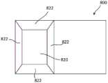
在一些变型中,插管附接设备可具有定位结构,该定位结构具有截头棱锥形形状,诸如例如,四边倾斜棱锥形状或其他锥形棱锥形形状。定位结构可位于可移动夹具部件、固定夹具部件或包围接纳插管的一部分的区域的另一个部件或表面上。例如,如图9A和图9B所示,可移动夹具部件800可具有由一个平坦表面820和四个成角度表面822形成的定位结构。定位和附接结构的多个表面820、822可允许插管或套管针牢固地定位并附接到外科机器人系统的机器人臂。例如,可移动夹具部件800可联接到外科机器人系统(例如,工具驱动器或机器人臂的端部),并且可移动夹具部件800的定位和附接结构可被构造成与设置在插管或套管针的一部分上的对应结构配合。当定位和附接结构与插管或套管针的对应结构配合时,定位和附接结构可将插管或套管针相对于机器人臂固定在适当的位置。可移动夹具部件800可由锁定组件(诸如本文所述的锁定部件中的任一个)在插管或套管针的一部分上保持或夹持在适当的位置。可移动夹具部件800可具有开口810(或另选地,销钉),该开口用于与附加结构接合以形成可移动夹具部件800可围绕其枢转的枢轴点。当设置时,可移动夹具部件800可在打开位置和闭合位置之间枢转,这与夹具部件230和夹具部件630的枢转类似。在一些变型中,可移动夹具部件800可具有狭槽,该狭槽允许锁定部件(诸如本文所述的锁定部件中的任一个)经由销钉或类似结构可移动地联接到可移动夹具部件800。In some variations, the cannula attachment device may have a positioning structure having a truncated pyramid shape, such as, for example, a four-sided inclined pyramid shape or other conical pyramid shape. The positioning structure may be located on a movable clamp member, a fixed clamp member, or another member or surface surrounding the area that receives a portion of the cannula. For example, as shown in FIGS. 9A and 9B , themovable clamp member 800 may have a positioning structure formed by oneflat surface 820 and fourangled surfaces 822 . Themultiple surfaces 820, 822 of the positioning and attachment structure may allow the cannula or trocar to be securely positioned and attached to the robotic arm of the surgical robotic system. For example, themovable gripper member 800 can be coupled to a surgical robotic system (eg, a tool driver or the end of a robotic arm), and the positioning and attachment features of themovable gripper member 800 can be configured to A corresponding structure on a portion of the needle mates. When cooperating with corresponding structures of the cannula or trocar, the positioning and attachment structures may secure the cannula or trocar in place relative to the robotic arm. Themovable clamp member 800 may be held or clamped in place by a locking assembly, such as any of the locking members described herein, on a portion of the cannula or trocar. Themovable clamp member 800 may have openings 810 (or alternatively, pins) for engagement with additional structures to form pivot points about which themovable clamp member 800 may pivot. When set,movable clamp member 800 can pivot between an open position and a closed position, similar to the pivoting ofclamp member 230 andclamp member 630 . In some variations, themovable clamp member 800 may have a slot that allows a locking member, such as any of the locking members described herein, to be movably coupled to themovable clamp member 800 via a pin or similar structure.

图10示出用于安装插管(诸如插管1080)的具有两件式锁定和释放系统的附接设备的另一示例性变型。附接设备1000的结构和/或功能可类似于本文描述的一个或多个其他附接设备,包括参考图2A至图6所描述的附接设备200,其变型包括例如:(1)弹簧1060,该弹簧被构造成将夹具部件1030偏置到闭合位置;以及(2)一个或多个止动表面1062,该一个或多个止动表面被构造成限制锁定部件(诸如例如,释放杆1040)的运动。附接设备1000可具有夹具部件1030(诸如杆或棒),该夹具部件可在打开位置和闭合位置之间移动。夹具部件1030可由诸如扭转弹簧的弹簧1060偏置到闭合位置,如图10所示。附接设备1000可具有释放杆或释放棒1040,该释放杆或释放棒可将夹具部件1030从闭合位置移动到打开位置。释放杆1040可具有可经由销钉1050移动地联接到夹具部件1030的第一端部。销钉1050可设置在形成在夹具部件1030中的狭槽1032中并被构造成沿着狭槽1032的长度滑动。释放杆1040还可具有第二端部,该第二端部具有用户接触点或柄部1042,该用户接触点或柄部可例如通过用户的手来致动以移动释放杆1040。释放杆1040的运动可受到一个或多个止动表面1062的限制。用户可沿方向1092推动或按压柄部1040,以使释放杆1040的第一端部沿方向1094移动(例如,使销钉1050沿着狭槽1032的长度在方向1094上平移)。当释放杆1040的第一端部沿方向1032移动时,释放杆1040可在夹具部件1030上施加力,该力可克服弹簧1060的偏置力并使夹具部件1030从闭合位置移动到打开位置。在打开位置,夹具部件1030可允许插管1080的一部分被沿方向1090插入附接设备1000的区域中。当用户停止按压柄部1040时,弹簧1060可将夹具部件1030偏置回到其闭合位置,并且夹具部件1030可闩锁到插管1080的部分上以将该部分保持在附接设备1000的区域中。FIG. 10 shows another exemplary variation of an attachment device with a two-piece locking and release system for installing a cannula, such ascannula 1080 .Attachment device 1000 may be similar in structure and/or function to one or more other attachment devices described herein, includingattachment device 200 described with reference to FIGS. 2A-6 , with variations including, for example: (1)Spring 1060 , the spring configured to bias theclamp member 1030 to the closed position; and (2) one ormore stop surfaces 1062 configured to restrain the locking member (such as, for example, the release lever 1040 ) )exercise. Theattachment device 1000 may have a clamp member 1030 (such as a rod or rod) that is movable between an open position and a closed position. Theclamp member 1030 may be biased to the closed position by aspring 1060, such as a torsion spring, as shown in FIG. 10 . Theattachment device 1000 can have a release lever orbar 1040 that can move theclamp member 1030 from the closed position to the open position.Release lever 1040 may have a first end movably coupled to clampmember 1030 viapin 1050 . Thepins 1050 may be disposed inslots 1032 formed in theclamp member 1030 and configured to slide along the length of theslots 1032 . Therelease lever 1040 can also have a second end with a user contact point or handle 1042 that can be actuated, eg, by a user's hand, to move therelease lever 1040 . Movement of therelease lever 1040 may be limited by one or more stop surfaces 1062 . A user can push orpress handle 1040 indirection 1092 to move the first end ofrelease lever 1040 in direction 1094 (eg, translatepin 1050 indirection 1094 along the length of slot 1032). When the first end of therelease lever 1040 is moved indirection 1032, therelease lever 1040 can exert a force on theclamp member 1030 that can overcome the biasing force of thespring 1060 and move theclamp member 1030 from the closed position to the open position. In the open position, theclamp member 1030 may allow a portion of thecannula 1080 to be inserted into the area of theattachment device 1000 in thedirection 1090 . When the user stops depressing thehandle 1040, thespring 1060 can bias theclamp member 1030 back to its closed position, and theclamp member 1030 can latch onto the portion of thecannula 1080 to hold the portion in the area where thedevice 1000 is attached middle.

与本文描述的锁定部件类似,释放杆1040可被设计为偏心锁定机构。例如,当释放杆1040处于图10所示的位置时,释放杆1040可处于偏心位置。在偏心位置,释放杆1040可被偏置以保持在偏心位置(例如,偏置而免于移动)。由于其偏心布置,释放杆1040可经受偏置力,该偏置力将释放杆1040保持在其锁定偏心位置。Similar to the locking components described herein, therelease lever 1040 may be designed as an over-center locking mechanism. For example, when therelease lever 1040 is in the position shown in FIG. 10, therelease lever 1040 may be in an off-center position. In the off-center position, therelease lever 1040 can be biased to remain in the off-center position (eg, biased from movement). Due to its eccentric arrangement, therelease lever 1040 may be subject to a biasing force that holds therelease lever 1040 in its locked eccentric position.

在一些变型中,附接设备1000可具有附加的夹具部件或与夹具部件1030隔开的固定表面。夹具部件1030和该附加的夹具部件可限定用于接纳插管1080的部分的区域。当插管1080的部分设置在由夹具部件1030和附加的夹具部件限定的区域中,并且用户释放释放杆1040以使得夹具部件1030移回到其闭合位置时,夹具部件1030和附加的夹具部件可围绕插管1080的部分夹持,以将其保持在由夹具部件1030和附加的夹具部件限定的区域内。In some variations, theattachment device 1000 may have additional clamp members or fixation surfaces spaced from theclamp members 1030 . Theclip member 1030 and the additional clip member may define an area for receiving a portion of thecannula 1080 . When the portion of thecannula 1080 is disposed in the area defined by theclamp member 1030 and the additional clamp member, and the user releases therelease lever 1040 to move theclamp member 1030 back to its closed position, theclamp member 1030 and the additional clamp member can be A portion of thecannula 1080 is clamped around to hold it within the area defined by theclamp member 1030 and additional clamp members.

与本文描述的其他插管附接设备类似,附接设备1000还可具有无菌适配器1012,该无菌适配器用于在夹具部件1030(其可以是非无菌的)和插管1080(其可以是无菌的)之间提供无菌屏障。Similar to the other cannula attachment devices described herein, theattachment device 1000 may also have asterile adapter 1012 for connecting between the clamp member 1030 (which may be non-sterile) and the cannula 1080 (which may be sterile) to provide a sterile barrier.

棘轮状变型ratchet

在一些变型中,插管附接设备可具有用于将插管附接到工具驱动器或机器人臂的机构,该机构允许插管很容易沿一个方向插入附接设备的区域中,但很难沿另一方向移除。在此类变型中,用户可能不需要致动附接设备的部件以便将插管插入并牢固地附接到附接设备。附接设备可被设计成当插管与附接设备的一部分接触时允许插管附接到附接设备。In some variations, the cannula attachment device may have a mechanism for attaching the cannula to a tool driver or robotic arm that allows easy insertion of the cannula into the area of the attachment device in one direction, but difficult along the Remove in the other direction. In such variations, the user may not need to actuate components of the attachment device in order to insert and securely attach the cannula to the attachment device. The attachment device may be designed to allow the cannula to be attached to the attachment device when the cannula is in contact with a portion of the attachment device.

例如,在图11中示出插管附接设备1100的示例性变型。插管附接设备1100被构造成接纳插管1180,该插管具有插管近侧部分1182和从插管近侧部分1182向远侧延伸的插管轴1184。For example, an exemplary variation of acannula attachment device 1100 is shown in FIG. 11 . Thecannula attachment device 1100 is configured to receive acannula 1180 having a cannulaproximal portion 1182 and acannula shaft 1184 extending distally from the cannulaproximal portion 1182 .

插管近侧部分1182可具有从插管近侧部分1182的一侧延伸的突起1190(例如,附接部分),其中突起1190的宽度大体成锥形。例如,突起119一般可具有:梯形棱柱形状,其中突起1190的两个相对侧朝向该突起的中心线成锥形;或者方形截头形状,其中突起1190的四个侧朝向该突起的中心线成锥形。突起1190可包括布置在第一锥形侧1196上的成角度齿1188和布置在第二锥形侧1194上的成角度齿1192。成角度齿1188、1192可以角度1198远离大体上垂直于插入方向(例如,插入方向1199)的方向成角度。角度1198可例如在约15度与约50度之间,或者在约20度与约45度之间,或者在约30度与约35度之间。成角度齿1188可在与成角度齿1192的方向相反的方向上成角度。The cannulaproximal portion 1182 may have a protrusion 1190 (eg, an attachment portion) extending from one side of the cannulaproximal portion 1182, wherein the width of theprotrusion 1190 is generally tapered. For example, the protrusions 119 may generally have: a trapezoidal prism shape in which the two opposite sides of theprotrusion 1190 taper toward the centerline of the protrusion; or a square truncated shape in which the four sides of theprotrusion 1190 taper toward the centerline of the protrusion Conical.Protrusion 1190 may includeangled teeth 1188 disposed on firsttapered side 1196 andangled teeth 1192 disposed on secondtapered side 1194 . Theangled teeth 1188, 1192 may be angled at anangle 1198 away from a direction generally perpendicular to the insertion direction (eg, insertion direction 1199). Theangle 1198 may be, for example, between about 15 degrees and about 50 degrees, or between about 20 degrees and about 45 degrees, or between about 30 degrees and about 35 degrees. Theangled teeth 1188 may be angled in a direction opposite the direction of theangled teeth 1192 .

插管附接设备1100可包括至少两个板1120、1130,该至少两个板跨用于接纳插管突起1190的开口或区域1152彼此相对。板1120可具有设置在面向开口1152的表面上的成角度齿1113,并且板1130可具有也设置在面向开口1152的表面上的成角度齿1111。成角度齿1111、1113可以角度1150相对于大体上垂直于插入方向1199的方向成角度。角度1150可例如在约15度与约50度之间,或者在约20度与约45度之间,或者在约30度与约35度之间。角度1150可对应于角度1198,使得成角度齿1188、1192可与成角度齿1111、1113配合地接合。与成角度齿1188、1192类似,成角度齿1111可在与成角度齿1113的方向相反的方向上成角度。可通过诸如弹簧1122的偏置元件施加偏置力F1来将板1120朝向板1130推进,并且可通过诸如弹簧1132的另一偏置元件施加偏置力F2来将板1130朝向板1120推进。Thecannula attachment device 1100 can include at least twoplates 1120 , 1130 opposing each other across an opening orarea 1152 for receiving thecannula protrusion 1190 .Plate 1120 may have angledteeth 1113 disposed on thesurface facing opening 1152 andplate 1130 may have angledteeth 1111 also disposed on thesurface facing opening 1152 . Theangled teeth 1111 , 1113 may be angled at anangle 1150 relative to a direction substantially perpendicular to theinsertion direction 1199 . Theangle 1150 may be, for example, between about 15 degrees and about 50 degrees, or between about 20 degrees and about 45 degrees, or between about 30 degrees and about 35 degrees.Angle 1150 may correspond toangle 1198 such thatangled teeth 1188 , 1192 may matingly engage withangled teeth 1111 , 1113 . Similar toangled teeth 1188 , 1192 , angledteeth 1111 may be angled in the opposite direction to that ofangled teeth 1113 .Plate 1120 may be urged towardplate 1130 by applying a biasing force F1 by a biasing element, such asspring 1122 , and may be urged towardplate 1120 by applying a biasing force F2 by another biasing element, such asspring 1132 .

为了将插管1180附接到附接设备1100,可将插管1180沿插入方向1199朝向附接设备1100移动,以将插管突起1190插入开口1152中。将插管突起1190插入开口1152中可使适配器板1120、1130分开,以使得成角度齿1188能够与成角度齿1111接合,并且成角度齿1192能够与成角度齿1113接合。一旦成角度齿1188、1192与成角度齿1111、1113接合,板1120、1130上的偏置力F1、F2使板1120、1130向下夹持在突起1190上,并固定或锁定插管附接设备1100和插管1180的联接。在一些变型中,可包括机械止动件和/或闩锁(例如,用于将板1120、1130锁定在夹持布置中)以帮助固定联接。一般来讲,只要没有克服弹簧偏置力F1、F2中的至少一个,插管突起1190和附接设备1100的相对运动仅被允许沿一个方向进行,使得插管突起1190很容易插入开口1152中,但基本上防止了插管突起被从开口1152移除。弹簧1122、1132可分别朝向彼此推进板1120、1130,以将突起1190保持在开口1152内,并分别保持成角度齿1111、1113与成角度齿1188、1192的接合。在一些变型中,可提供机构(例如,按钮、杆、柄部、挤压机构)以通过克服弹簧偏置力来压缩弹簧1122、1132并且将板1120、1130充分分开以允许从开口1152移除插管突起1190,从而使插管1180从附接设备1100(以及工具驱动器或机器人臂)脱离。有利地,在图11所示的示例性变型中,附接设备1100和插管1180可联接而无需致动第二机构(例如,附接设备1100和插管1180可经由单手操作联接以将插管1180“扣入并锁定”到附接设备1100中),并且插管1180可牢固地保持在附接设备1100上,直到第二机构被激活以允许附接设备1100和插管1180脱开。To attach thecannula 1180 to theattachment device 1100 , thecannula 1180 can be moved toward theattachment device 1100 in theinsertion direction 1199 to insert thecannula protrusion 1190 into theopening 1152 . Insertingcannula protrusion 1190 intoopening 1152 separatesadapter plates 1120 , 1130 so thatangled teeth 1188 can engageangled teeth 1111 andangled teeth 1192 can engageangled teeth 1113 . Once theangled teeth 1188, 1192 are engaged with theangled teeth 1111, 1113, the biasing forces F1, F2 on theplates 1120, 1130 clamp theplates 1120, 1130 down on theprotrusions 1190 and secure or lock the cannula attachment Coupling ofdevice 1100 andcannula 1180. In some variations, mechanical stops and/or latches (eg, to lock theplates 1120, 1130 in the clamping arrangement) may be included to help secure the coupling. Generally speaking, relative movement of thecannula protrusion 1190 and theattachment device 1100 is only allowed in one direction so that thecannula protrusion 1190 is easily inserted into theopening 1152 as long as at least one of the spring biasing forces F1 , F2 is not overcome. , but substantially prevent the cannula protrusion from being removed fromopening 1152.Springs 1122, 1132 can urgeplates 1120, 1130, respectively, toward each other to retainprotrusion 1190 withinopening 1152 and maintain engagement ofangled teeth 1111, 1113 withangled teeth 1188, 1192, respectively. In some variations, a mechanism (eg, button, lever, handle, squeeze mechanism) may be provided to compress thesprings 1122 , 1132 by overcoming the spring biasing force and separate theplates 1120 , 1130 sufficiently to allow removal from theopening 1152 The cannula protrudes 1190, thereby disengaging thecannula 1180 from the attachment device 1100 (and the tool driver or robotic arm). Advantageously, in the exemplary variation shown in FIG. 11,attachment device 1100 andcannula 1180 can be coupled without actuating a second mechanism (eg,attachment device 1100 andcannula 1180 can be coupled via one-handed operation to connectcannula 1180 "snap and lock" into attachment device 1100), andcannula 1180 can be held securely onattachment device 1100 until a second mechanism is activated to allowattachment device 1100 andcannula 1180 to disengage .

插管附接设备的其他变型也可以不同的方式利用成角度齿或类似的成角度特征,诸如用于容纳不同形状的插管突起。例如,虽然图11所示的变型可被构造成接纳突起1190,该突起一般具有梯形棱柱形状(其中突起的两个相对侧朝向突起的中心线成锥形)或方形截头形状(其中突起的四个侧朝向突起的中心线成锥形),但其他变型可被构造成接纳:其他锥形突起形状,诸如截头圆锥形状,其中环形成角度脊与插管适配器中的成角度齿或脊接合;或者非锥形突起形状,诸如具有成角度齿或脊的矩形棱柱形状或圆柱形状。Other variations of cannula attachment devices may also utilize angled teeth or similar angled features in different ways, such as for accommodating differently shaped cannula protrusions. For example, although the variation shown in FIG. 11 may be configured to receiveprotrusions 1190, the protrusions generally have a trapezoidal prism shape (in which opposite sides of the protrusion taper toward the centerline of the protrusion) or a square frustum shape (in which the protrusion's The four sides taper toward the centerline of the protrusion), but other variations may be configured to accommodate: other tapered protrusion shapes, such as frusto-conical shapes, where the rings form angled ridges with angled teeth or ridges in the cannula adapter engagement; or non-conical protruding shapes such as rectangular prismatic or cylindrical shapes with angled teeth or ridges.

在一些变型中,用于将非无菌插管附接设备1100与无菌插管1180分开的无菌适配器元件可包括装配在插管附接设备1100上的非无菌成角度齿1111、1113和插管1180上的无菌成角度齿1188、1192之间的盖布或其他无菌薄片(例如,塑料)。塑料可用作在齿1111、1113、1188、1192之间摩擦减小的承载表面,从而进一步促进插管突起1190插入插管附接设备1100中。In some variations, the sterile adapter element used to separate the non-sterilecannula attachment device 1100 from thesterile cannula 1180 may include non-sterileangled teeth 1111 , 1113 fitted on the cannula attachment device 1100 A drape or other sterile sheet (eg, plastic) between the sterileangled teeth 1188, 1192 on thecannula 1180. Plastic can be used as a friction-reduced bearing surface between theteeth 1111 , 1113 , 1188 , 1192 to further facilitate insertion of thecannula protrusion 1190 into thecannula attachment device 1100 .

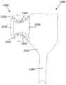
如图12所示,在另一示例性变型中,插管附接设备1300被构造成接纳插管1380,该插管具有插管近侧部分1382和从插管近侧部分1382向远侧延伸的插管轴1384。与图11中所示并在上面所述的插管1180类似,插管近侧部分1382可具有从插管近侧部分1382的一侧延伸的突起1390(例如,附接部分),其中突起1390的宽度一般成锥形(例如,一般具有梯形棱柱形状,其中突起1390的两个相对侧朝向突起1390的中心线成锥形)。突起1390可包括齿1392或以齿条状构型布置在突起1390的至少两个锥形侧1394、1396上的类似结构。插管附接设备1300可包括至少两个旋转的小齿轮状元件1320、1330,这些小齿轮状元件跨接纳插管突起1390的空间1352彼此相对。小齿轮状元件1320、1330中的每一个都可包括齿轮的至少一部分,其中小齿轮状元件1320、1330的第一侧可以是平坦的,而小齿轮状元件1320、1330的第二侧可以是圆的并且具有设置于其上的齿1324。小齿轮状元件1320、1330的齿1324可被构造成接合插管1380上的齿1392。小齿轮状元件1320可被构造成围绕点1322旋转,而小齿轮状元件1330可被构造成围绕点1332旋转。12, in another exemplary variation, thecannula attachment device 1300 is configured to receive acannula 1380 having a cannulaproximal portion 1382 and extending distally from the cannulaproximal portion 1382 Thecannula shaft 1384. Similar to thecannula 1180 shown in FIG. 11 and described above, the cannulaproximal portion 1382 may have a protrusion 1390 (eg, an attachment portion) extending from one side of the cannulaproximal portion 1382, wherein theprotrusion 1390 The width of the is generally tapered (eg, generally has a trapezoidal prism shape, with two opposite sides of theprotrusion 1390 tapering toward the centerline of the protrusion 1390). Theprotrusions 1390 may includeteeth 1392 or similar structures disposed on at least twotapered sides 1394, 1396 of theprotrusions 1390 in a rack-like configuration. Thecannula attachment apparatus 1300 may include at least two rotating pinion-like elements 1320 , 1330 that oppose each other across thespace 1352 that receives thecannula protrusion 1390 . Each of the pinion-like elements 1320, 1330 can comprise at least a portion of a gear, wherein a first side of the pinion-like elements 1320, 1330 can be flat and a second side of the pinion-like elements 1320, 1330 can be It is round and hasteeth 1324 disposed thereon.Teeth 1324 of pinion-like elements 1320 , 1330 may be configured to engageteeth 1392 oncannula 1380 . Pinion-like element 1320 may be configured to rotate aboutpoint 1322 and pinion-like element 1330 may be configured to rotate aboutpoint 1332 .

当插管突起1390沿方向1399移动并插入两个小齿轮状元件1320、1330之间的空间1352中时,小齿轮状元件1320可沿方向1398旋转并且小齿轮状元件1330可沿旋转方向1397旋转,并且插管突起1390上的齿1392可与小齿轮状元件1320、1330上的齿1324接合。一旦插管突起1390已插入两个小齿轮状元件1320、1330之间的空间1352中,并且齿1392已与齿1324接合,则小齿轮状元件1320、1330可通过干涉元件作用在小齿轮状元件1320、1330的平坦表面上而被锁定在适当的位置。例如,干涉元件可包括弹簧,这些弹簧将小齿轮状元件1320、1330朝向彼此推进以向下夹持在突起1390上并固定附接设备1300和插管1380的联接。插管突起1390可很容易插入空间1352中,但由于弹簧将小齿轮状元件1320、1330朝向彼此推进以将突起1390保持在空间1352中,因此基本上防止了插管突起被从空间1352移除。干涉元件可包括附加的机械止动件,用于帮助固定或锁定联接。可包括机构(例如,按钮、杆、柄部、挤压机构等)以克服由干涉元件施加的力,以便使小齿轮状元件1320、1330沿相反方向旋转以允许从空间1352移除插管突起1390,从而使插管1380从工具驱动器或机器人臂脱离。同样,有利地,在该变型中,插管附接设备1300和插管1380可联接而无需致动第二机构(例如,附接设备1300和插管1380可经由单手操作联接以将插管1380“扣入并锁定”到附接设备1300中),并且插管1380可牢固地保持在附接设备1300上,直到第二机构被激活以允许附接设备1300和插管1380脱开。When thecannula protrusion 1390 is moved in thedirection 1399 and inserted into thespace 1352 between the two pinion-like elements 1320, 1330, the pinion-like element 1320 can rotate in thedirection 1398 and the pinion-like element 1330 can rotate in therotational direction 1397 , and theteeth 1392 on thecannula protrusion 1390 can engage with theteeth 1324 on the pinion-like elements 1320, 1330. Once thecannula protrusion 1390 has been inserted into thespace 1352 between the two pinion-like elements 1320, 1330, and theteeth 1392 have engaged with theteeth 1324, the pinion-like elements 1320, 1330 can act on the pinion-like elements through the interferingelement 1320, 1330 are locked in place on the flat surfaces. For example, the interfering elements may include springs that urge the pinion-like elements 1320 , 1330 toward each other to clamp down on theprotrusion 1390 and secure the coupling of theattachment device 1300 and thecannula 1380 . Thecannula protrusion 1390 can be easily inserted into thespace 1352, but is substantially prevented from being removed from thespace 1352 due to the spring urging the pinion-like elements 1320, 1330 towards each other to retain theprotrusion 1390 in thespace 1352 . The interference element may include additional mechanical stops to help secure or lock the coupling. Mechanisms (eg, buttons, levers, handles, squeeze mechanisms, etc.) may be included to overcome the force applied by the interfering element to rotate the pinion-like elements 1320, 1330 in opposite directions to allow removal of the cannula protrusions from thespace 1352 1390, thereby disengaging thecannula 1380 from the tool driver or robotic arm. Also, advantageously, in this variation,cannula attachment device 1300 andcannula 1380 can be coupled without actuating a second mechanism (eg,attachment device 1300 andcannula 1380 can be coupled via one-handed operation to attach thecannula 1380 "snap and lock" into the attachment device 1300), and thecannula 1380 can be held securely on theattachment device 1300 until a second mechanism is activated to allow theattachment device 1300 andcannula 1380 to disengage.

与插管附接设备1100类似,插管附接设备1300的其他变型可适应插管突起1390的不同形状(例如,梯形棱柱形、方形截头形、截头圆锥形等)。并且,虽然小齿轮状元件1320、1330在图12中被示出为大体半圆形的,但在其他变型中,小齿轮状元件1320、1330可以是圆形的(例如,具有辐条的盘状或环状等),或者可包括任何合适的圆形段或圆段。此外,在其他变型中,小齿轮状元件1320、1330可具有变化的半径,使得随着小齿轮状元件1320、1330旋转以接纳插管突起1390,其中齿1324与齿1392接合的小齿轮状元件1320、1330的半径可变得越来越窄,从而进一步确保小齿轮状元件1320、1330和插管突起1390之间的接合。Similar tocannula attachment device 1100, other variations ofcannula attachment device 1300 may accommodate different shapes of cannula protrusions 1390 (eg, trapezoidal prism, square frustum, frustoconical, etc.). Also, while the pinion-like elements 1320, 1330 are shown in FIG. 12 as being generally semi-circular, in other variations the pinion-like elements 1320, 1330 may be circular (eg, disk-shaped with spokes) or annular, etc.), or may include any suitable circular segment or segment. Additionally, in other variations, the pinion-like elements 1320 , 1330 may have varying radii such that as the pinion-like elements 1320 , 1330 rotate to receive thecannula protrusion 1390 , the pinion-like elements withteeth 1324 engaged withteeth 1392 The radii of 1320 , 1330 may become narrower to further ensure engagement between pinion-like elements 1320 , 1330 andcannula protrusion 1390 .

在一些变型中,用于将非无菌插管附接设备1300与无菌插管1380分开的无菌适配器元件可包括设置在每个非无菌小齿轮状元件1320、1330和无菌突起1390之间的惰齿轮,该惰齿轮可提供非无菌部分和无菌部分之间的物理分离,同时仍允许基本上类似于上面参考图12所述来操作机构。附加地或另选地,可在非无菌齿1324和无菌齿1392之间设置盖布或其他无菌薄片。In some variations, a sterile adapter element for separating the non-sterilecannula attachment device 1300 from thesterile cannula 1380 may include asterile protrusion 1390 disposed on each of the non-sterile pinion-like elements 1320 , 1330 An idler gear in between, which can provide physical separation between the non-sterile and sterile portions, while still allowing the mechanism to operate substantially similar to that described above with reference to FIG. 12 . Additionally or alternatively, a drape or other sterile sheet may be provided between thenon-sterile teeth 1324 and thesterile teeth 1392.

如图13所示,在另一示例性变型中,插管附接设备1500被构造成接纳插管1580,其中插管1580具有插管近侧部分1582和从插管近侧部分1582向远侧延伸的插管轴1584。插管近侧部分1582可具有从插管近侧部分1582的一侧延伸的突起1590,其中突起1590具有限定至少一个凹陷1592的波状外形表面。凹陷1592被构造成与插管附接设备1500上的至少一个特征接合。例如,插管附接设备1500可包括至少一个可充气囊袋1520,该可充气囊袋可诸如通过阀和/或泵系统选择性地填充有流体(例如,空气或其他气体、液体等)。在一个示例中,突起1590可包括凹陷1592,诸如围绕突起1590的周边延伸的环形通道,并且囊袋1520可以是被构造成与环形通道配合并接合的圆环状结构。在另一示例中,突起1590包括具有凹陷1592的至少一个侧,该凹陷被构造成与插管附接设备1500的单个囊袋1520接合。在又一示例中,突起1590包括具有相应凹陷1592的至少两个相对侧,这些凹陷中的每一个都被构造成接合两个囊袋1520中的一个,这两个囊袋跨插管附接设备1500上的空间或开口1552彼此相对。As shown in FIG. 13 , in another exemplary variation, thecannula attachment device 1500 is configured to receive acannula 1580 having a cannulaproximal portion 1582 and a distal portion from the cannulaproximal portion 1582Extended cannula shaft 1584. The cannulaproximal portion 1582 can have aprotrusion 1590 extending from one side of the cannulaproximal portion 1582 , wherein theprotrusion 1590 has a contoured surface defining at least onerecess 1592 . Therecess 1592 is configured to engage with at least one feature on thecannula attachment device 1500. For example, thecannula attachment device 1500 can include at least oneinflatable bladder 1520 that can be selectively filled with a fluid (eg, air or other gas, liquid, etc.), such as through a valve and/or pump system. In one example,protrusion 1590 may include arecess 1592, such as an annular channel extending around the perimeter ofprotrusion 1590, andpocket 1520 may be an annular structure configured to mate and engage the annular channel. In another example,protrusion 1590 includes at least one side having arecess 1592 configured to engage asingle pocket 1520 ofcannula attachment device 1500 . In yet another example,protrusion 1590 includes at least two opposing sides withcorresponding recesses 1592, each of which is configured to engage one of twopockets 1520 that are attached across the cannula The spaces oropenings 1552 on thedevice 1500 are opposite each other.

在脱开模式中,囊袋1520可放气以允许插管1580的突起1590被插入开口1552中。一旦突起1590被插入开口1552中,就可对囊袋1520充气。在一些变型中,当突起1590以预定距离或深度插入开口1520中时,突起1590可自动触发阀以打开囊袋1520并对其充气。触发机构可以是机械触发器或电触发器,诸如接触传感器、压力传感器、光学传感器等。附加地或另选地,用户可手动地发起囊袋1520的充气。在其中在插管附接设备1500中布置有多个囊袋1520的变型中,可将多个囊袋对称地布置并且一般充气到相同程度,以便使突起1590在开口1552中自动对中和/或以其他方式对准,这可有助于对插管1580的其他部分进行定位和对准。附加地或另选地,多个囊袋1520中的至少一些可充气到不同程度,以便补偿突起1590和/或插管的其他部分的不对准。类似地,在其中存在单个囊袋1520的变型中,囊袋1520可充气到选定程度,以便对准插管和/或补偿插管1580中的固有不对准。为了将插管1580的突起1590从附接设备1500脱开或移除,可对囊袋1520放气,使得其不再与突起1590中的凹陷1592接合。可致动诸如按钮或开关的机构以释放阀或泵系统的其他部件以允许囊袋1520放气。In the detached mode, thebladder 1520 can be deflated to allow theprotrusion 1590 of thecannula 1580 to be inserted into theopening 1552. Onceprotrusion 1590 is inserted intoopening 1552,bladder 1520 can be inflated. In some variations, whenprotrusion 1590 is inserted intoopening 1520 by a predetermined distance or depth,protrusion 1590 may automatically trigger a valve to open and inflatebladder 1520. The trigger mechanism may be a mechanical trigger or an electrical trigger, such as a contact sensor, pressure sensor, optical sensor, or the like. Additionally or alternatively, the user may initiate inflation of thebladder 1520 manually. In variations in whichmultiple pockets 1520 are arranged in thecannula attachment device 1500, the multiple pockets may be symmetrically arranged and generally inflated to the same extent so as to self-center theprotrusions 1590 in theopenings 1552 and/or Or otherwise aligned, which may aid in positioning and aligning other portions of thecannula 1580. Additionally or alternatively, at least some of the plurality ofbladders 1520 may be inflated to varying degrees in order to compensate for misalignment of theprotrusions 1590 and/or other portions of the cannula. Similarly, in variations in which asingle bladder 1520 is present, thebladder 1520 may be inflated to a selected degree to align the cannula and/or compensate for inherent misalignment in thecannula 1580. To disengage or removeprotrusion 1590 ofcannula 1580 fromattachment device 1500,bladder 1520 can be deflated so that it no longer engagesrecess 1592 inprotrusion 1590. A mechanism, such as a button or switch, can be actuated to release a valve or other component of the pump system to allow thebladder 1520 to deflate.

在一些变型中,用于将非无菌插管附接设备1500与无菌插管1580分开的无菌适配器元件还可包括装配在插管附接设备1500上的非无菌囊袋1520和插管1580的突起1590之间的盖布或其他无菌薄片(例如,塑料)。In some variations, the sterile adapter element used to separate the non-sterilecannula attachment device 1500 from thesterile cannula 1580 may also include anon-sterile pouch 1520 fitted on thecannula attachment device 1500 and a cannula A drape or other sterile sheet (eg, plastic) between theprotrusions 1590 of thetube 1580.

凸轮锁定变型Cam lock variant

在一些变型中,用于将插管附接到工具驱动器的设备可包括凸轮锁定机构。当附接和释放插管时,插管附接设备可使用单手操作。附接设备可牢固地保持插管,直到用户致动释放机构以使插管从该设备脱开;因此,附接设备可防止插管的意外释放。附接设备可能需要来自用户的最小量的力来附接和释放插管。例如,附接设备可能需要用户施加小于五磅的力来附接和释放插管。In some variations, the apparatus for attaching the cannula to the tool driver may include a cam locking mechanism. The cannula attachment device can be operated with one hand when attaching and releasing the cannula. The attachment device can hold the cannula securely until the user actuates the release mechanism to disengage the cannula from the device; thus, the attachment device can prevent accidental release of the cannula. The attachment device may require a minimal amount of force from the user to attach and release the cannula. For example, the attachment device may require the user to apply less than five pounds of force to attach and release the cannula.

插管附接设备的凸轮锁定机构可包括闩锁,当插管被插入附接设备的腔或凹部中时,闩锁自动地闩锁到插管中。闩锁可被诸如扭转弹簧的偏置元件偏置到其闩锁位置(例如,闭合位置)。用户可致动杆以将闩锁移动或旋转到打开位置,使得插管的一部分可被插入附接设备的凹部中。杆可经由齿轮系统连接到闩锁,该齿轮系统用作力倍增器。例如,齿轮系统可允许用户施加小于由扭转弹簧施加的力的力,以便克服扭转弹簧力并移动闩锁。用户可在杆上施加四磅的力,该力可通过齿轮比为例如至少1.5:1的齿轮系统倍增,以便帮助用户克服六磅的扭转弹簧。当凸轮锁定机构已将插管固定在适当的位置时,插管附接设备能够抵抗作用在插管上的外力。例如,当凸轮锁定机构的闩锁已闩锁到插管上时,闩锁可具有近乎越轴对准,当在插管上施加了侧向拉力时,该近乎越轴对准减少了闩锁的潜在运动或旋转。附接设备可能能够抵抗施加到附接设备的扭转力、弯曲力和其他力。The cam locking mechanism of the cannula attachment device may include a latch that automatically latches into the cannula when the cannula is inserted into the lumen or recess of the attachment device. The latch may be biased to its latched position (eg, closed position) by a biasing element, such as a torsion spring. The user can actuate the lever to move or rotate the latch to the open position so that a portion of the cannula can be inserted into the recess of the attachment device. The lever can be connected to the latch via a gear system that acts as a force multiplier. For example, a gear system may allow a user to apply a force less than the force exerted by the torsion spring in order to overcome the torsion spring force and move the latch. The user may apply four pounds of force on the rod, which may be multiplied by a gear system with a gear ratio of at least 1.5:1, for example, to help the user overcome the six-pound torsion spring. The cannula attachment device is able to resist external forces acting on the cannula when the cam locking mechanism has secured the cannula in place. For example, when the latch of the cam locking mechanism has latched onto the cannula, the latch may have a near-over-axis alignment that reduces the latching when a lateral pull is applied to the cannula potential motion or rotation. The attachment device may be able to resist torsional, bending, and other forces applied to the attachment device.

在一些变型中,附接设备可具有用于感测和/或识别套管针或插管的感测能力。例如,附接设备可具有传感器,该传感器检测凸轮锁定机构的闩锁的位置,以便确定闩锁是否已闩锁到插管或套管针上。例如,传感器可以是能够检测磁场的换能器,诸如霍尔效应传感器。霍尔效应传感器可通过检测设置在闩锁的一部分上的磁体的位置来操作。作为另一示例,附接设备可具有传感器,该传感器确定已插入到附接设备中的套管针或插管的类型。例如,传感器可以是能够识别某些类型的套管针或插管的磁极或磁场传感器。In some variations, the attachment device may have sensing capabilities for sensing and/or identifying the trocar or cannula. For example, the attachment device may have a sensor that detects the position of the latch of the cam locking mechanism in order to determine if the latch is latched onto the cannula or trocar. For example, the sensor may be a transducer capable of detecting a magnetic field, such as a Hall effect sensor. Hall effect sensors may operate by detecting the position of a magnet provided on a portion of the latch. As another example, the attachment device may have a sensor that determines the type of trocar or cannula that has been inserted into the attachment device. For example, the sensor may be a magnetic pole or magnetic field sensor capable of identifying certain types of trocars or cannulas.

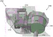
图14至图15B示出用于将插管(诸如插管1780)附接到外科台的工具驱动器或机器人臂的附接设备的示例性变型,其中附接设备包括凸轮锁定机构。图14为附接设备1700的透视图,并且图15A至图15B为处于两种不同构型的附接设备1700的凸轮锁定机构的放大视图。如图14所示,附接设备1700包括诸如杆1710的致动构件。杆1710可连接到齿轮组件1720。当被致动时,杆1710可驱动齿轮组件1720的一个或多个齿轮以移动锁定构件诸如闩锁1740,如图15A至图15B所示。Figures 14-15B illustrate an exemplary variation of an attachment device for attaching a cannula, such ascannula 1780, to a tool driver or robotic arm of a surgical table, wherein the attachment device includes a cam locking mechanism. 14 is a perspective view of theattachment apparatus 1700, and FIGS. 15A-15B are enlarged views of the cam locking mechanism of theattachment apparatus 1700 in two different configurations. As shown in FIG. 14 ,attachment device 1700 includes an actuation member such asrod 1710 .Rod 1710 may be connected to gearassembly 1720 . When actuated,lever 1710 can drive one or more gears ofgear assembly 1720 to move a locking member such aslatch 1740, as shown in Figures 15A-15B.

插管1780的结构和/或功能可类似于本文描述的一个或多个其他插管。例如,插管1780可具有近侧部分1782,诸如例如毂部、配件、连接器等。插管1780的近侧部分1782可包括附接部分1790。附接部分1790可从近侧部分1782的一侧延伸。插管1780还可具有轴1784(在图14中部分地示出),该轴从近侧部分1782向远侧延伸。Cannula 1780 may be similar in structure and/or function to one or more of the other cannulas described herein. For example, thecannula 1780 may have aproximal portion 1782 such as, for example, a hub, a fitting, a connector, and the like.Proximal portion 1782 ofcannula 1780 may includeattachment portion 1790 . Theattachment portion 1790 can extend from one side of theproximal portion 1782 . Thecannula 1780 may also have a shaft 1784 (shown in part in FIG. 14 ) that extends distally from theproximal portion 1782 .

附接设备1700的闩锁1740可在闭合位置(如图14和图15B所示)和打开位置(如图15A所示)之间移动。例如,闩锁1740可包括突起1748,该突起被构造成闩锁到形成在插管1780的附接部分1790中的对应成形的凹部1794中。另选地,闩锁1740可包括凹部,该凹部被构造成接纳设置在插管1780的附接部分1790上的对应成形的突起。当突起1748被闩锁到凹部1794中时,闩锁1740可确保附接部分1790被牢固地附接到外科台的工具驱动器或机器人臂。闩锁1740可通过诸如弹簧1746的偏置元件偏置到闭合位置。当闩锁1740处于闭合位置时,闩锁1740的突起1748可设置在附接设备1700的空间或区域1750中,附接部分1790可插入其中。但是,当突起1748设置在区域1750中时,突起1748可基本上防止附接部分1790被完全插入区域1750中。例如,突起1748的表面可接触附接部分1790的前沿表面并防止附接部分1790被进一步插入区域1750中。Thelatch 1740 of theattachment device 1700 is movable between a closed position (shown in Figures 14 and 15B) and an open position (shown in Figure 15A). For example, thelatch 1740 may include aprotrusion 1748 configured to latch into a correspondingly shapedrecess 1794 formed in theattachment portion 1790 of thecannula 1780 . Alternatively, thelatch 1740 may include a recess configured to receive a correspondingly shaped protrusion provided on theattachment portion 1790 of thecannula 1780 . When theprotrusion 1748 is latched into therecess 1794, thelatch 1740 can ensure that theattachment portion 1790 is securely attached to the tool driver or robotic arm of the surgical table. Thelatch 1740 can be biased to the closed position by a biasing element, such as aspring 1746 . When thelatch 1740 is in the closed position, theprotrusion 1748 of thelatch 1740 may be disposed in the space orarea 1750 of theattachment device 1700 into which theattachment portion 1790 may be inserted. However, when theprotrusions 1748 are provided in theregion 1750 , theprotrusions 1748 can substantially prevent theattachment portion 1790 from being fully inserted into theregion 1750 . For example, the surface ofprotrusion 1748 may contact the leading surface ofattachment portion 1790 and preventattachment portion 1790 from being inserted further intoregion 1750 .

因此,当将插管1780附接到附接设备1700时,用户可能需要将闩锁1740移动到示于图5A中的打开位置,使得突起1748并未设置在用于接纳插管1780的附接部分1790的区域1750中。用户可例如通过按压杆1710来致动杆1710,以移动闩锁1740。有利地,用户可使用单手致动杆1710。杆1710可驱动齿轮组件1720的一个或多个齿轮和连杆(例如,齿轮1722、1726和连杆1734)的运动以移动闩锁1740。为了允许闩锁1740移动到打开位置,必须克服弹簧1746的偏置力。但是,基于齿轮组件1720的齿轮的相对尺寸(该齿轮组件可被设计成用作具有合适的齿轮比的力倍增器),用户施加的力可小于弹簧1746的偏置力,以便克服弹簧偏置力并将闩锁1740移动到打开位置。例如,杆1710可附接到第一齿轮1722。第一齿轮1722可具有齿1724,该齿设置在相距第一齿轮1722的中心1730的距离1731处。第一齿轮1722的齿1724可被构造成与第二齿轮1726的齿1728接合。第二齿轮1726的齿1728可设置在相距第二齿轮1726的中心1732的距离1733处。当距离1731大于距离1733时,两个齿轮1722、1726可用作力倍增器,从而允许用户施加较小的力来克服弹簧1746的偏置力。例如,如果第一齿轮和第二齿轮之间的齿轮比为约1.5:1,则用户可能只需要施加四磅力以便克服六磅的弹簧偏置力。在一些变型中,两个齿轮1722、1726可与一个或多个附加齿轮串联连接,这可能会提高齿轮组件1720的有效齿轮比和力倍增效果。两个齿轮1722、1726的旋转可驱动连杆1734的运动。当连杆1734移动到其如图15A所示的位置时,连杆1734的一部分1738可与闩锁1740的一部分1742接合,从而使闩锁1740移动到其打开位置。Thus, when attaching thecannula 1780 to theattachment device 1700, the user may need to move thelatch 1740 to the open position shown in FIG.section 1790 inarea 1750. The user may actuate thelever 1710 to move thelatch 1740, eg, by pressing thelever 1710. Advantageously, the user can use the one-handed actuation lever 1710.Lever 1710 may drive movement of one or more gears and links of gear assembly 1720 (eg, gears 1722 , 1726 and link 1734 ) to movelatch 1740 . To allow thelatch 1740 to move to the open position, the biasing force of thespring 1746 must be overcome. However, based on the relative dimensions of the gears of gear assembly 1720 (which can be designed to act as a force multiplier with suitable gear ratios), the user-applied force can be less than the biasing force ofspring 1746 in order to overcome the spring bias force and move thelatch 1740 to the open position. For example,rod 1710 may be attached tofirst gear 1722 . Thefirst gear 1722 may have teeth 1724 disposed at adistance 1731 from thecenter 1730 of thefirst gear 1722 . The teeth 1724 of thefirst gear 1722 may be configured to engage with theteeth 1728 of thesecond gear 1726 . Theteeth 1728 of thesecond gear 1726 may be disposed at adistance 1733 from thecenter 1732 of thesecond gear 1726 . Whendistance 1731 is greater thandistance 1733 , the twogears 1722 , 1726 may act as force multipliers, allowing the user to apply less force to overcome the biasing force ofspring 1746 . For example, if the gear ratio between the first gear and the second gear is about 1.5:1, the user may only need to apply four pounds of force in order to overcome the six pounds of spring bias. In some variations, the twogears 1722 , 1726 may be connected in series with one or more additional gears, which may increase the effective gear ratio and force multiplication effect of thegear assembly 1720 . Rotation of the twogears 1722 , 1726 may drive the movement of thelink 1734 . When thelink 1734 is moved to its position as shown in Figure 15A, aportion 1738 of thelink 1734 can engage with aportion 1742 of thelatch 1740, thereby moving thelatch 1740 to its open position.

一旦闩锁1740处于其打开位置,用户就可将插管1780的附接部分1790插入附接设备1700的区域1750中,如图15A所示。然后,用户可释放杆1710,以允许弹簧1746将闩锁1740偏置回到其闭合位置,如图15B所示。当闩锁1740被偏置回到其闭合位置时,闩锁的突起1748可设置在附接部分1790的凹部1814中,从而将附接部分1790固定在附接设备1700的区域1750中。在闭合位置中,闩锁1740可具有近乎越轴或偏心对准,使得当在插管1780上施加了拉力时,闩锁1740可抵抗运动或旋转。在示例性变型中,附接设备可被设计成抵抗高达250英寸磅(in-lb)的力矩和/或抵抗高达37N的力。Once thelatch 1740 is in its open position, the user may insert theattachment portion 1790 of thecannula 1780 into theregion 1750 of theattachment device 1700, as shown in Figure 15A. The user can then release thelever 1710 to allow thespring 1746 to bias thelatch 1740 back to its closed position, as shown in Figure 15B. When thelatch 1740 is biased back to its closed position, the latch'sprotrusion 1748 may be disposed in the recess 1814 of theattachment portion 1790 , thereby securing theattachment portion 1790 in thearea 1750 of theattachment device 1700 . In the closed position, thelatch 1740 can have a nearly off-axis or eccentric alignment such that when a pulling force is applied to thecannula 1780, thelatch 1740 can resist movement or rotation. In an exemplary variation, the attachment device may be designed to resist torque up to 250 inch pounds (in-lb) and/or resist force up to 37N.

区域1750可成形为对应于附接部分1790的形状。在变型中,区域1750可被设计成容纳直径为约42毫米(mm)的插管1780的一部分(例如,附接部分1790),但在其他变型中,可对附接设备进行修改以容纳直径更大或更小的插管。在一些变型中,附接部分17910可具有圆柱形或椭圆形的横截面形状(例如,卵形或细长圆形)。例如,椭圆形横截面形状的细长边可有助于防止插管相对于区域1750旋转和平移。在其他变型中,附接部分1790可具有不同的形状(例如,具有梯形棱柱形状、方形截头形状、截头棱锥形形状等),并且区域1750可对应地成形为接纳附接部分1790。在一些方面,区域1750可成锥形(并且附接部分1790可对应地成锥形),以便于附接部分1790更容易插入区域1750中。Region 1750 may be shaped to correspond to the shape ofattachment portion 1790 . In variations,region 1750 may be designed to accommodate a portion of cannula 1780 (eg, attachment portion 1790 ) having a diameter of approximately 42 millimeters (mm), although in other variations, the attachment device may be modified to accommodate the diameter Larger or smaller cannula. In some variations, the attachment portion 17910 may have a cylindrical or elliptical cross-sectional shape (eg, oval or elongated circular). For example, the elongated sides of the oval cross-sectional shape can help prevent rotation and translation of the cannula relative toregion 1750. In other variations, theattachment portion 1790 may have a different shape (eg, having a trapezoidal prism shape, a square truncated shape, a truncated pyramid shape, etc.), and theregion 1750 may be correspondingly shaped to receive theattachment portion 1790 . In some aspects,region 1750 may be tapered (andattachment portion 1790 may be correspondingly tapered) to facilitate easier insertion ofattachment portion 1790 intoregion 1750 .

附接设备1700可包括一个或多个传感器,用于感测附接设备1700的其他部件的位置和/或已插入附接设备1700中的套管针或插管的类型。例如,传感器1760可定位为靠近闩锁1740的部分1742并且可检测闩锁1740何时处于其闭合位置并且已闩锁到插管上。传感器1760可以是光学传感器、磁性传感器或响应于闩锁1740的运动而提供读取信号或电信号的其他类型的传感器。在一些变型中,闩锁1740可包括一个或多个磁体,该一个或多个磁体可生成磁场,该磁场可被传感器1760检测到以确定闩锁1740的位置并且确定套管针或插管是否已被插入附接设备1700中。在另一示例中,当套管针或插管被插入附接设备1700中时,附接设备1700可具有传感器1770,该传感器定位为靠近套管针或插管(诸如插管1780)的表面。另选地或附加地,传感器1770可以是光学传感器、磁性传感器或响应于套管针或插管的存在而提供读取或电信号的其他类型的传感器。套管针或插管可包括磁体或可生成磁场的其他电子部件,该磁场可由传感器1770检测到并用于检测套管针或插管是否已适当地放置并附接到附接设备1700和/或套管针或插管的类型(例如,套管针或插管的尺寸是否一定、或是否被构造成接纳某种类型和尺寸的器械)。附加地或另选地,套管针或插管可具有条形码或者可被传感器1770检测到(例如,扫描,成像)以确定套管针或插管的类型的其他类型的识别特征。Theattachment device 1700 may include one or more sensors for sensing the position of other components of theattachment device 1700 and/or the type of trocar or cannula that has been inserted into theattachment device 1700 . For example,sensor 1760 can be positionedproximate portion 1742 oflatch 1740 and can detect whenlatch 1740 is in its closed position and latched onto the cannula.Sensor 1760 may be an optical sensor, a magnetic sensor, or other type of sensor that provides a read or electrical signal in response to movement oflatch 1740 . In some variations, thelatch 1740 can include one or more magnets that can generate a magnetic field that can be detected by thesensor 1760 to determine the position of thelatch 1740 and to determine whether the trocar or cannula is has been inserted into theattachment device 1700 . In another example, when the trocar or cannula is inserted into theattachment device 1700, theattachment device 1700 may have asensor 1770 positioned proximate the surface of the trocar or cannula, such as thecannula 1780 . Alternatively or additionally,sensor 1770 may be an optical sensor, a magnetic sensor, or other type of sensor that provides a read or electrical signal in response to the presence of a trocar or cannula. The trocar or cannula can include a magnet or other electronic component that can generate a magnetic field that can be detected by thesensor 1770 and used to detect whether the trocar or cannula has been properly placed and attached to theattachment device 1700 and/or The type of trocar or cannula (eg, whether the trocar or cannula is sized or configured to receive a certain type and size of instrument). Additionally or alternatively, the trocar or cannula may have a barcode or other type of identifying feature that can be detected (eg, scanned, imaged) by thesensor 1770 to determine the type of trocar or cannula.

在一些变型中,用于将非无菌附接设备1700与无菌插管1780分开的无菌适配器元件1792还可包括装配在附接设备1700上的非无菌闩锁1740和插管1780的附接部分1790之间的盖布或其他无菌薄片(例如,塑料)。无菌适配器元件17912可以是充分柔性的,使得当非无菌闩锁1740和附接部分1790彼此接合时,该无菌适配器元件可与它们的形状相符。In some variations, thesterile adapter element 1792 for separating thenon-sterile attachment device 1700 from thesterile cannula 1780 may also include anon-sterile latch 1740 fitted on theattachment device 1700 and the cannula 1780 A drape or other sterile sheet (eg, plastic) betweenattachment portions 1790. The sterile adapter element 17912 can be sufficiently flexible so that when thenon-sterile latch 1740 and theattachment portion 1790 are engaged with each other, the sterile adapter element can conform to their shape.

在上述方法表明某些事件按某种顺序发生的情况下,某些事件的排序可能会被修改。另外,如果可能,某些事件可以在并行过程中同时执行,以及如上所述顺序地执行。The ordering of certain events may be modified in cases where the above method indicates that certain events occur in a certain order. Additionally, if possible, certain events may be performed concurrently in parallel processes, as well as sequentially as described above.

在上文所述的示意图和/或实施方案表示以某些取向或位置布置的某些部件的情况下,可以修改部件的布置。虽然已经具体示出并描述了实施方案,但是应当理解,可以进行形式和细节上的各种变化。本文所述的装置和/或方法的任何部分可以除互相排斥的组合之外的任何组合进行组合。本文所述的实施方案可包括所述的不同实施方案的功能、部件和/或特征的各种组合和/或子组合。Where the schematic diagrams and/or embodiments described above represent certain components arranged in certain orientations or positions, the arrangement of the components may be modified. While embodiments have been shown and described in detail, it will be understood that various changes in form and detail may be made. Any portion of the apparatus and/or methods described herein may be combined in any combination other than mutually exclusive combinations. The embodiments described herein may include various combinations and/or subcombinations of the functions, components and/or features of the different embodiments described.

Claims (20)

Translated fromChinese
1.一种用于将插管附接到机器人外科系统的装置,所述装置包括:1. A device for attaching a cannula to a robotic surgical system, the device comprising:第一夹具部件,所述第一夹具部件被构造成在打开位置和闭合位置之间枢转;a first clamp member configured to pivot between an open position and a closed position;第二夹具部件,所述第二夹具部件与所述第一夹具部件隔开,所述第一夹具部件和所述第二夹具部件限定被构造成接纳所述插管的一部分的区域,所述第一夹具部件和所述第二夹具部件被构造成当所述第一夹具部件处于所述闭合位置时,将所述插管的所述部分保持在所述区域中;a second clamp member spaced from the first clamp member, the first clamp member and the second clamp member defining an area configured to receive a portion of the cannula, the the first clamp member and the second clamp member are configured to retain the portion of the cannula in the region when the first clamp member is in the closed position;锁定部件,所述锁定部件联接到所述第一夹具部件并且被构造成使所述第一夹具部件在所述打开位置和所述闭合位置之间枢转;以及a locking member coupled to the first clamp member and configured to pivot the first clamp member between the open position and the closed position; and定位结构,所述定位结构设置在所述第一夹具部件和所述第二夹具部件中的至少一个上,所述定位结构被构造成与设置在所述插管的所述部分上的对应结构配合。a positioning structure provided on at least one of the first clamp member and the second clamp member, the positioning structure being configured to correspond to a corresponding structure provided on the portion of the cannula Cooperate.2.根据权利要求1所述的装置,还包括无菌屏障,所述无菌屏障被构造成当所述插管的所述部分被接纳在所述区域中时,将所述第一夹具部件和所述第二夹具部件与所述插管分开。2. The device of claim 1, further comprising a sterile barrier configured to lock the first clamp member when the portion of the cannula is received in the region and the second clamp member is separated from the cannula.3.根据权利要求1所述的装置,其中所述锁定部件被构造成在其中所述锁定部件将所述第一夹具部件定位在所述打开位置的解锁位置和其中所述锁定部件将所述第一夹具部件定位在所述闭合位置的锁定偏心位置之间枢转。3. The device of claim 1, wherein the locking member is configured in an unlocked position wherein the locking member positions the first clamp member in the open position and wherein the locking member positions the The first clamp member is positioned to pivot between a locked off-center position in the closed position.4.根据权利要求3所述的装置,其中所述锁定部件被构造成当所述锁定部件处于所述锁定偏心位置时,将所述第一夹具部件锁定在所述闭合位置。4. The device of claim 3, wherein the locking member is configured to lock the first clamp member in the closed position when the locking member is in the locking eccentric position.5.根据权利要求3所述的装置,其中所述第一夹具部件具有形成于其中的狭槽,所述狭槽沿着所述第一夹具部件的部分长度延伸。5. The apparatus of claim 3, wherein the first clamp member has a slot formed therein, the slot extending along a portion of the length of the first clamp member.6.根据权利要求5所述的装置,其中所述锁定部件包括第一端部和第二端部,所述第一端部可沿着形成在所述第一夹具部件中的所述狭槽的长度移动,所述第二端部被构造成移动以使所述锁定部件在所述解锁位置和所述锁定偏心位置之间枢转。6. The device of claim 5, wherein the locking member includes a first end and a second end, the first end being along the slot formed in the first clamp member The second end is configured to move to pivot the locking member between the unlocked position and the locking eccentric position.7.根据权利要求6所述的装置,其中当所述锁定部件从所述解锁位置枢转到所述锁定偏心位置时,所述锁定部件的所述第一端部沿着所述狭槽在第一方向上移动,7. The device of claim 6, wherein the first end of the locking member is positioned along the slot when the locking member is pivoted from the unlocked position to the locking off-center position move in the first direction,其中当所述锁定部件从所述锁定偏心位置枢转到所述解锁位置时,所述锁定部件的所述第一端部沿着所述狭槽在与所述第一方向相反的第二方向上移动。wherein the first end of the locking member is in a second direction opposite the first direction along the slot when the locking member is pivoted from the locking eccentric position to the unlocking position move up.8.根据权利要求1所述的装置,其中所述定位结构包括至少一个锥形表面,所述至少一个锥形表面被构造成将所述插管的所述部分相对于所述第一夹具部件和所述第二夹具部件以预定取向引导到所述第一夹具部件和所述第二夹具部件之间的所述区域中。8. The device of claim 1, wherein the positioning structure includes at least one tapered surface configured to position the portion of the cannula relative to the first clamp member and the second clamp part is guided into the region between the first clamp part and the second clamp part in a predetermined orientation.9.根据权利要求8所述的装置,其中所述定位结构被构造成当所述第一夹具部件处于所述闭合位置时,闩锁到设置在所述插管的所述部分上的所述结构中并将所述插管的所述部分保持在由所述第一夹具部件和所述第二夹具部件限定的所述区域内。9. The device of claim 8, wherein the detent structure is configured to latch to the latch provided on the portion of the cannula when the first clamp member is in the closed position into structure and retain the portion of the cannula within the area defined by the first clamp member and the second clamp member.10.根据权利要求8所述的装置,其中所述定位结构包括形成三角形突起的两个锥形表面。10. The device of claim 8, wherein the locating structure comprises two tapered surfaces forming triangular protrusions.11.根据权利要求1所述的装置,其中所述定位结构为截头棱锥形。11. The device of claim 1, wherein the positioning structure is a frusto-pyramid shape.12.根据权利要求1所述的装置,还包括弹簧,所述弹簧被构造成将所述第一夹具部件偏置在所述闭合位置。12. The device of claim 1, further comprising a spring configured to bias the first clamp member in the closed position.13.根据权利要求1所述的装置,还包括支撑件,13. The apparatus of claim 1, further comprising a support,其中所述支撑件经由枢轴联接到所述第一夹具部件,wherein the support is coupled to the first clamp member via a pivot,其中所述支撑件还联接到所述第二夹具部件。wherein the support is also coupled to the second clamp member.14.一种方法,包括:14. A method comprising:将用于插管的附接装置的锁定部件定位在解锁位置,其中所述锁定部件操作地联接到第一夹具部件并且被构造成使所述第一夹具部件在打开位置和闭合位置之间枢转,其中当所述锁定部件被定位在所述解锁位置时,所述第一夹具部件被定位在所述打开位置;Positioning a locking member of an attachment device for a cannula in an unlocked position, wherein the locking member is operatively coupled to the first clamp member and configured to pivot the first clamp member between an open position and a closed position rotating, wherein when the locking member is positioned in the unlocked position, the first clamp member is positioned in the open position;将所述插管的一部分插入所述第一夹具部件和第二夹具部件之间的区域中;以及inserting a portion of the cannula into the area between the first clamp member and the second clamp member; and将所述锁定部件从所述解锁位置移动到锁定偏心位置以使所述第一夹具部件枢转到所述闭合位置,所述第一夹具部件和所述第二夹具部件被构造成当所述第一夹具部件处于所述闭合位置时,将所述插管的所述部分保持在所述区域中。Moving the locking member from the unlocked position to a locking eccentric position to pivot the first clamp member to the closed position, the first clamp member and the second clamp member are configured to The first clamp member retains the portion of the cannula in the region when the first clamp member is in the closed position.15.根据权利要求14所述的方法,其中所述锁定部件被构造成在所述解锁位置和所述锁定偏心位置之间枢转。15. The method of claim 14, wherein the locking member is configured to pivot between the unlocked position and the locked off-center position.16.根据权利要求15所述的方法,其中当所述锁定部件处于所述锁定偏心位置时,将所述锁定部件朝向所述锁定偏心位置偏置。16. The method of claim 15, wherein the locking member is biased toward the locking off-center position when the locking member is in the locking off-center position.17.根据权利要求15所述的方法,其中所述锁定部件包括第一端部和第二端部,所述第一端部可沿着形成在所述第一夹具部件中的狭槽的长度移动,所述第二端部被构造成移动以使所述锁定部件在所述解锁位置和所述锁定偏心位置之间枢转。17. The method of claim 15, wherein the locking member includes a first end and a second end, the first end being along the length of a slot formed in the first clamp member Moving, the second end is configured to move to pivot the locking member between the unlocked position and the locked off-center position.18.根据权利要求17所述的方法,其中当所述锁定部件从所述解锁位置枢转到所述锁定偏心位置时,所述锁定部件的所述第一端部沿着所述狭槽在第一方向上移动,并且18. The method of claim 17, wherein the first end of the locking member is positioned along the slot when the locking member is pivoted from the unlocked position to the locking off-center position move in the first direction, and其中当所述锁定部件从所述锁定偏心位置枢转到所述解锁位置时,所述锁定部件的所述第一端部沿着所述狭槽在与所述第一方向相反的第二方向上移动。wherein the first end of the locking member is in a second direction opposite the first direction along the slot when the locking member is pivoted from the locking eccentric position to the unlocking position move up.19.根据权利要求14所述的方法,其中将所述插管以预定取向插入所述区域中,其中设置在所述第一夹具部件和所述第二夹具部件中的至少一个上的定位结构与设置在所述插管的所述部分上的对应结构配合。19. The method of claim 14, wherein the cannula is inserted into the region in a predetermined orientation, wherein a positioning feature is provided on at least one of the first clamp member and the second clamp member Co-operates with corresponding structures provided on the portion of the cannula.20.根据权利要求19所述的方法,其中所述定位结构包括第一锥形表面和第二锥形表面,所述第一锥形表面和所述第二锥形表面形成三角形突起,并且20. The method of claim 19, wherein the locating structure comprises a first tapered surface and a second tapered surface, the first tapered surface and the second tapered surface forming a triangular protrusion, and其中所述三角形突起被构造成当所述第一夹具部件处于所述闭合位置时,闩锁到所述插管的所述部分中并将所述插管的所述部分保持在由所述第一夹具部件和所述第二夹具部件限定的所述区域内。wherein the triangular protrusion is configured to latch into the portion of the cannula and retain the portion of the cannula in position by the first clamp member when the first clamp member is in the closed position A clamp part and the second clamp part define the region.
CN201880054545.7A2017-08-212018-08-21Cannula attachment apparatus and method for surgical robotic systemActiveCN111278372B (en)

Applications Claiming Priority (5)

Application NumberPriority DateFiling DateTitle
US201762548292P2017-08-212017-08-21
US62/5482922017-08-21
US15/999,399US11076883B2 (en)2017-08-212018-08-20Cannula attachment devices and methods for a surgical robotic system
US15/9993992018-08-20
PCT/US2018/047388WO2019040531A1 (en)2017-08-212018-08-21Cannula attachment devices and methods for a surgical robotic system

Publications (2)

Publication NumberPublication Date
CN111278372Atrue CN111278372A (en)2020-06-12
CN111278372B CN111278372B (en)2023-08-08

Family

ID=63714008

Family Applications (1)

Application NumberTitlePriority DateFiling Date
CN201880054545.7AActiveCN111278372B (en)2017-08-212018-08-21Cannula attachment apparatus and method for surgical robotic system

Country Status (9)

CountryLink
US (3)US11076883B2 (en)
EP (1)EP3644876B1 (en)
JP (1)JP7106635B2 (en)
KR (2)KR102532826B1 (en)
CN (1)CN111278372B (en)
AU (1)AU2018321328B2 (en)
BR (1)BR112020001344B1 (en)
CA (1)CA3070029C (en)
WO (1)WO2019040531A1 (en)

Cited By (4)

* Cited by examiner, † Cited by third party
Publication numberPriority datePublication dateAssigneeTitle
CN114305706A (en)*2021-12-172022-04-12上海微创医疗机器人(集团)股份有限公司Mechanical arm connecting mechanism, sleeve pipe assembly and surgical robot system
CN115199874A (en)*2021-04-082022-10-18苹果公司Reconfigurable rack ecosystem
CN117897115A (en)*2022-03-242024-04-16瑞德医疗机器股份有限公司Mounting tool for holding
US12372193B2 (en)2021-04-082025-07-29Apple Inc.Reconfigurable stand ecosystem

Families Citing this family (15)

* Cited by examiner, † Cited by third party
Publication numberPriority datePublication dateAssigneeTitle
KR102553082B1 (en)*2014-03-172023-07-10인튜어티브 서지컬 오퍼레이션즈 인코포레이티드Surgical cannula mounts and related systems and methods
US10624671B2 (en)*2016-12-212020-04-21Ethicon LlcTrocar attachment devices and methods
US11076883B2 (en)*2017-08-212021-08-03Verb Surgical Inc.Cannula attachment devices and methods for a surgical robotic system
US11090122B2 (en)2019-02-252021-08-17Verb Surgical Inc.Systems and methods for magnetic sensing and docking with a trocar
US11529734B2 (en)*2019-10-312022-12-20Verb Surgical Inc.Systems and methods for visual sensing of and docking with a trocar
CN115461008A (en)2020-04-242022-12-09威博外科公司Remote center of motion control for surgical robot
US11793500B2 (en)2020-09-302023-10-24Verb Surgical Inc.Adjustable force and ball bearing attachment mechanism for docking cannulas to surgical robotic arms
US20220096120A1 (en)2020-09-302022-03-31Verb Surgical Inc.Systems and methods for docking surgical robotic arms
US11793597B2 (en)2020-09-302023-10-24Verb Surgical Inc.Attachment mechanism for docking cannulas to surgical robotic arms
JP7736238B2 (en)*2020-09-302025-09-09バーブ サージカル インコーポレイテッド Systems and methods for docking a surgical robotic arm
US12023116B2 (en)*2020-12-212024-07-02Cilag Gmbh InternationalDynamic trocar positioning for robotic surgical system
CN113598957A (en)*2021-07-052021-11-05深圳康诺思腾科技有限公司Sleeve pipe adapter and surgical robot
CN115869073A (en)*2021-09-302023-03-31深圳康诺思腾科技有限公司Sleeve pipe adapter and surgical robot
US20250275826A1 (en)*2022-04-192025-09-04Clearpoint Neuro, Inc.Adjustable depth stop system for surgical accessory
US20240042609A1 (en)*2022-08-032024-02-08Covidien LpSurgical robotic system with access port storage

Citations (9)

* Cited by examiner, † Cited by third party
Publication numberPriority datePublication dateAssigneeTitle
US5807378A (en)*1995-06-071998-09-15Sri InternationalSurgical manipulator for a telerobotic system
US20060161136A1 (en)*1997-11-212006-07-20Intuitive Surgical Inc.Surgical accessory clamp and system method
US20080208202A1 (en)*2007-01-252008-08-28Jeffrey WilliamsAdaptable tool removal device and method
CN101378798A (en)*2006-01-312009-03-04史密斯医疗Asd公司Safety needle assembly with modified drug connection
CA2830214A1 (en)*2011-03-142012-09-20Ethicon Endo-Surgery, Inc.Surgical stapling instruments
WO2014011539A2 (en)*2012-07-102014-01-16Lifeline Scientific, Inc.Cannula with floating clamping member
CN103998085A (en)*2011-09-072014-08-20塞考利特公司Cannula tips, tissue attachment rings, and methods of delivering and using the same
WO2015142814A1 (en)*2014-03-172015-09-24Intuitive Surgical Operations, Inc.Surgical cannula mounts and related systems and methods
CN106572853A (en)*2014-06-132017-04-19伊西康内外科有限责任公司Closure lockout systems for surgical instruments

Family Cites Families (30)

* Cited by examiner, † Cited by third party
Publication numberPriority datePublication dateAssigneeTitle
US7314331B1 (en)*2004-08-112008-01-01Tibor KorosMulti-position locking mechanisms for clamping assemblies
US10357184B2 (en)2012-06-212019-07-23Globus Medical, Inc.Surgical tool systems and method
US9096033B2 (en)2007-06-132015-08-04Intuitive Surgical Operations, Inc.Surgical system instrument sterile adapter
US20090043246A1 (en)2007-08-072009-02-12Dominguez Guillermo ManuelMagnetic Surgical Device to Manipulate Tissue in Laparoscopic Surgeries Performed with a Single Trocar or Via Natural Orifices
WO2009092059A2 (en)2008-01-162009-07-23Catheter Robotics, Inc.Remotely controlled catheter insertion system
US8423182B2 (en)2009-03-092013-04-16Intuitive Surgical Operations, Inc.Adaptable integrated energy control system for electrosurgical tools in robotic surgical systems
AU2013249076B2 (en)*2012-04-202018-03-29Jai SinghRepositionable medical instrument support systems, devices, and methods
US9737364B2 (en)2012-05-142017-08-22Vanderbilt UniversityLocal magnetic actuation of surgical devices
KR101997566B1 (en)2012-08-072019-07-08삼성전자주식회사Surgical robot system and control method thereof
KR102395425B1 (en)2014-03-172022-05-09인튜어티브 서지컬 오퍼레이션즈 인코포레이티드Alignment and engagement for teleoperated actuated surgical instruments
KR102536576B1 (en)2014-03-172023-05-26인튜어티브 서지컬 오퍼레이션즈 인코포레이티드Surgical cannulas and related systems and methods of identifying surgical cannulas
KR20230162122A (en)2015-02-202023-11-28스트리커 코포레이션Sterile barrier assembly, mounting system, and method for coupling surgical components
DE102015219332A1 (en)2015-10-072017-04-13Robert Bosch Gmbh Sensor device and robot assembly with the sensor device
US10687904B2 (en)2016-08-162020-06-23Ethicon LlcRobotics tool exchange
US10695134B2 (en)2016-08-252020-06-30Verily Life Sciences LlcMotion execution of a robotic system
US10238422B2 (en)*2016-12-152019-03-26Ethicon, LlcTrocar support
US10624671B2 (en)*2016-12-212020-04-21Ethicon LlcTrocar attachment devices and methods
EP3606400B1 (en)2017-04-072022-03-09Auris Health, Inc.Patient introducer alignment
US11076883B2 (en)*2017-08-212021-08-03Verb Surgical Inc.Cannula attachment devices and methods for a surgical robotic system
JP2021511087A (en)2017-11-152021-05-06スティーラブル インストゥルメンツ エヌヴイSteerable Instruments Nv Controllable maneuverable equipment
US11432885B2 (en)2017-12-282022-09-06Cilag Gmbh InternationalSensing arrangements for robot-assisted surgical platforms
CN111556735A (en)*2018-01-042020-08-18柯惠Lp公司Systems and assemblies for mounting surgical accessories to robotic surgical systems and providing access therethrough
WO2019204699A1 (en)2018-04-192019-10-24GYS Tech, LLC d/b/a Cardan RoboticsMethods and systems for controlling a surgical robot
CN111134849B (en)2018-11-022024-05-31威博外科公司Surgical robot system
US11090122B2 (en)2019-02-252021-08-17Verb Surgical Inc.Systems and methods for magnetic sensing and docking with a trocar
US11529734B2 (en)2019-10-312022-12-20Verb Surgical Inc.Systems and methods for visual sensing of and docking with a trocar
US11819288B2 (en)2020-03-192023-11-21Verb Surgical Inc.Trocar pose estimation using machine learning for docking surgical robotic arm to trocar
US11793597B2 (en)2020-09-302023-10-24Verb Surgical Inc.Attachment mechanism for docking cannulas to surgical robotic arms
US20220096120A1 (en)2020-09-302022-03-31Verb Surgical Inc.Systems and methods for docking surgical robotic arms
US11793500B2 (en)2020-09-302023-10-24Verb Surgical Inc.Adjustable force and ball bearing attachment mechanism for docking cannulas to surgical robotic arms

Patent Citations (11)

* Cited by examiner, † Cited by third party
Publication numberPriority datePublication dateAssigneeTitle
US5807378A (en)*1995-06-071998-09-15Sri InternationalSurgical manipulator for a telerobotic system
US20060161136A1 (en)*1997-11-212006-07-20Intuitive Surgical Inc.Surgical accessory clamp and system method
CN101378798A (en)*2006-01-312009-03-04史密斯医疗Asd公司Safety needle assembly with modified drug connection
US20080208202A1 (en)*2007-01-252008-08-28Jeffrey WilliamsAdaptable tool removal device and method
CA2830214A1 (en)*2011-03-142012-09-20Ethicon Endo-Surgery, Inc.Surgical stapling instruments
CN103998085A (en)*2011-09-072014-08-20塞考利特公司Cannula tips, tissue attachment rings, and methods of delivering and using the same
WO2014011539A2 (en)*2012-07-102014-01-16Lifeline Scientific, Inc.Cannula with floating clamping member
WO2015142814A1 (en)*2014-03-172015-09-24Intuitive Surgical Operations, Inc.Surgical cannula mounts and related systems and methods
CN106102642A (en)*2014-03-172016-11-09直观外科手术操作公司 Surgical cannula mount and related systems and methods
US20170086930A1 (en)*2014-03-172017-03-30Intuitive Surgical Operations, Inc.Surgical cannula mounts and related systems and methods
CN106572853A (en)*2014-06-132017-04-19伊西康内外科有限责任公司Closure lockout systems for surgical instruments

Cited By (7)

* Cited by examiner, † Cited by third party
Publication numberPriority datePublication dateAssigneeTitle
CN115199874A (en)*2021-04-082022-10-18苹果公司Reconfigurable rack ecosystem
US12372193B2 (en)2021-04-082025-07-29Apple Inc.Reconfigurable stand ecosystem
US12429920B2 (en)2021-04-082025-09-30Apple Inc.Reconfigurable stand ecosystem
CN114305706A (en)*2021-12-172022-04-12上海微创医疗机器人(集团)股份有限公司Mechanical arm connecting mechanism, sleeve pipe assembly and surgical robot system
WO2023109951A1 (en)*2021-12-172023-06-22上海微创医疗机器人(集团)股份有限公司Mechanical arm connecting mechanism, sleeve assembly and surgical robot system
CN114305706B (en)*2021-12-172024-01-23上海微创医疗机器人(集团)股份有限公司Mechanical arm connecting mechanism, sleeve assembly and surgical robot system
CN117897115A (en)*2022-03-242024-04-16瑞德医疗机器股份有限公司Mounting tool for holding

Also Published As

Publication numberPublication date
US20190053824A1 (en)2019-02-21
US11076883B2 (en)2021-08-03
BR112020001344B1 (en)2024-04-30
CN111278372B (en)2023-08-08
AU2018321328B2 (en)2020-11-05
US20210330351A1 (en)2021-10-28
CA3070029C (en)2022-07-12
EP3644876A1 (en)2020-05-06
KR20200033917A (en)2020-03-30
KR20220032120A (en)2022-03-15
KR102369834B1 (en)2022-03-03
WO2019040531A1 (en)2019-02-28
EP3644876B1 (en)2024-06-26
US12343037B2 (en)2025-07-01
CA3070029A1 (en)2019-02-28
US20250288321A1 (en)2025-09-18
JP7106635B2 (en)2022-07-26
KR102532826B1 (en)2023-05-17
BR112020001344A2 (en)2020-08-11
AU2018321328A1 (en)2020-01-30
EP3644876C0 (en)2024-06-26
JP2020530340A (en)2020-10-22

Similar Documents

PublicationPublication DateTitle
CN111278372B (en)Cannula attachment apparatus and method for surgical robotic system
JP6880138B2 (en) Surgical cannula mounts and related systems and methods
US12097006B2 (en)Latch release for surgical instrument
JP2008289902A (en) Surgical manipulator for teleoperated robot system
JP2019063550A (en) Surgical device for stabilizing or immobilizing moving tissue
KR20230079167A (en) Systems and methods for docking a surgical robot arm
WO2023181299A1 (en)Retention attachment
WO2023181298A1 (en)Retention attachment

Legal Events

DateCodeTitleDescription
PB01Publication
PB01Publication
SE01Entry into force of request for substantive examination
GR01Patent grant
GR01Patent grant

[8]ページ先頭

©2009-2025 Movatter.jp