CN111272144A - Depth Sensing Camera System - Google Patents
Depth Sensing Camera SystemDownload PDFInfo
- Publication number
- CN111272144A CN111272144ACN201911228518.XACN201911228518ACN111272144ACN 111272144 ACN111272144 ACN 111272144ACN 201911228518 ACN201911228518 ACN 201911228518ACN 111272144 ACN111272144 ACN 111272144A
- Authority
- CN
- China
- Prior art keywords
- radiation
- sensor
- output signal
- depth
- lens
- Prior art date
- Legal status (The legal status is an assumption and is not a legal conclusion. Google has not performed a legal analysis and makes no representation as to the accuracy of the status listed.)
- Granted
Links
Images


Classifications
- G—PHYSICS
- G06—COMPUTING OR CALCULATING; COUNTING
- G06T—IMAGE DATA PROCESSING OR GENERATION, IN GENERAL
- G06T7/00—Image analysis
- G06T7/50—Depth or shape recovery
- G06T7/55—Depth or shape recovery from multiple images
- G06T7/586—Depth or shape recovery from multiple images from multiple light sources, e.g. photometric stereo
- H—ELECTRICITY
- H04—ELECTRIC COMMUNICATION TECHNIQUE
- H04N—PICTORIAL COMMUNICATION, e.g. TELEVISION
- H04N13/00—Stereoscopic video systems; Multi-view video systems; Details thereof
- H04N13/20—Image signal generators
- H04N13/271—Image signal generators wherein the generated image signals comprise depth maps or disparity maps
- G—PHYSICS
- G01—MEASURING; TESTING
- G01C—MEASURING DISTANCES, LEVELS OR BEARINGS; SURVEYING; NAVIGATION; GYROSCOPIC INSTRUMENTS; PHOTOGRAMMETRY OR VIDEOGRAMMETRY
- G01C11/00—Photogrammetry or videogrammetry, e.g. stereogrammetry; Photographic surveying
- G—PHYSICS
- G01—MEASURING; TESTING
- G01B—MEASURING LENGTH, THICKNESS OR SIMILAR LINEAR DIMENSIONS; MEASURING ANGLES; MEASURING AREAS; MEASURING IRREGULARITIES OF SURFACES OR CONTOURS
- G01B11/00—Measuring arrangements characterised by the use of optical techniques
- G01B11/02—Measuring arrangements characterised by the use of optical techniques for measuring length, width or thickness
- G—PHYSICS
- G01—MEASURING; TESTING
- G01B—MEASURING LENGTH, THICKNESS OR SIMILAR LINEAR DIMENSIONS; MEASURING ANGLES; MEASURING AREAS; MEASURING IRREGULARITIES OF SURFACES OR CONTOURS
- G01B11/00—Measuring arrangements characterised by the use of optical techniques
- G01B11/22—Measuring arrangements characterised by the use of optical techniques for measuring depth
- G—PHYSICS
- G01—MEASURING; TESTING
- G01S—RADIO DIRECTION-FINDING; RADIO NAVIGATION; DETERMINING DISTANCE OR VELOCITY BY USE OF RADIO WAVES; LOCATING OR PRESENCE-DETECTING BY USE OF THE REFLECTION OR RERADIATION OF RADIO WAVES; ANALOGOUS ARRANGEMENTS USING OTHER WAVES
- G01S17/00—Systems using the reflection or reradiation of electromagnetic waves other than radio waves, e.g. lidar systems
- G01S17/88—Lidar systems specially adapted for specific applications
- G01S17/89—Lidar systems specially adapted for specific applications for mapping or imaging
- G01S17/894—3D imaging with simultaneous measurement of time-of-flight at a 2D array of receiver pixels, e.g. time-of-flight cameras or flash lidar
- G—PHYSICS
- G01—MEASURING; TESTING
- G01S—RADIO DIRECTION-FINDING; RADIO NAVIGATION; DETERMINING DISTANCE OR VELOCITY BY USE OF RADIO WAVES; LOCATING OR PRESENCE-DETECTING BY USE OF THE REFLECTION OR RERADIATION OF RADIO WAVES; ANALOGOUS ARRANGEMENTS USING OTHER WAVES
- G01S7/00—Details of systems according to groups G01S13/00, G01S15/00, G01S17/00
- G01S7/48—Details of systems according to groups G01S13/00, G01S15/00, G01S17/00 of systems according to group G01S17/00
- G01S7/481—Constructional features, e.g. arrangements of optical elements
- G01S7/4816—Constructional features, e.g. arrangements of optical elements of receivers alone
- G—PHYSICS
- G06—COMPUTING OR CALCULATING; COUNTING
- G06T—IMAGE DATA PROCESSING OR GENERATION, IN GENERAL
- G06T7/00—Image analysis
- G06T7/50—Depth or shape recovery
- G06T7/55—Depth or shape recovery from multiple images
- H—ELECTRICITY
- H04—ELECTRIC COMMUNICATION TECHNIQUE
- H04N—PICTORIAL COMMUNICATION, e.g. TELEVISION
- H04N13/00—Stereoscopic video systems; Multi-view video systems; Details thereof
- H04N13/20—Image signal generators
- H04N13/204—Image signal generators using stereoscopic image cameras
- H04N13/254—Image signal generators using stereoscopic image cameras in combination with electromagnetic radiation sources for illuminating objects
- H—ELECTRICITY
- H04—ELECTRIC COMMUNICATION TECHNIQUE
- H04N—PICTORIAL COMMUNICATION, e.g. TELEVISION
- H04N23/00—Cameras or camera modules comprising electronic image sensors; Control thereof
- H04N23/20—Cameras or camera modules comprising electronic image sensors; Control thereof for generating image signals from infrared radiation only
- H04N23/21—Cameras or camera modules comprising electronic image sensors; Control thereof for generating image signals from infrared radiation only from near infrared [NIR] radiation
- H—ELECTRICITY
- H04—ELECTRIC COMMUNICATION TECHNIQUE
- H04N—PICTORIAL COMMUNICATION, e.g. TELEVISION
- H04N23/00—Cameras or camera modules comprising electronic image sensors; Control thereof
- H04N23/60—Control of cameras or camera modules
- H—ELECTRICITY
- H04—ELECTRIC COMMUNICATION TECHNIQUE
- H04N—PICTORIAL COMMUNICATION, e.g. TELEVISION
- H04N23/00—Cameras or camera modules comprising electronic image sensors; Control thereof
- H04N23/60—Control of cameras or camera modules
- H04N23/698—Control of cameras or camera modules for achieving an enlarged field of view, e.g. panoramic image capture
- G—PHYSICS
- G06—COMPUTING OR CALCULATING; COUNTING
- G06T—IMAGE DATA PROCESSING OR GENERATION, IN GENERAL
- G06T2207/00—Indexing scheme for image analysis or image enhancement
- G06T2207/10—Image acquisition modality
- G06T2207/10028—Range image; Depth image; 3D point clouds
- G—PHYSICS
- G06—COMPUTING OR CALCULATING; COUNTING
- G06T—IMAGE DATA PROCESSING OR GENERATION, IN GENERAL
- G06T2207/00—Indexing scheme for image analysis or image enhancement
- G06T2207/10—Image acquisition modality
- G06T2207/10048—Infrared image
- G—PHYSICS
- G06—COMPUTING OR CALCULATING; COUNTING
- G06T—IMAGE DATA PROCESSING OR GENERATION, IN GENERAL
- G06T2207/00—Indexing scheme for image analysis or image enhancement
- G06T2207/20—Special algorithmic details
- G06T2207/20084—Artificial neural networks [ANN]
- H—ELECTRICITY
- H04—ELECTRIC COMMUNICATION TECHNIQUE
- H04N—PICTORIAL COMMUNICATION, e.g. TELEVISION
- H04N13/00—Stereoscopic video systems; Multi-view video systems; Details thereof
- H04N2013/0074—Stereoscopic image analysis
- H04N2013/0081—Depth or disparity estimation from stereoscopic image signals
Landscapes
- Engineering & Computer Science (AREA)
- Physics & Mathematics (AREA)
- Multimedia (AREA)
- Signal Processing (AREA)
- General Physics & Mathematics (AREA)
- Health & Medical Sciences (AREA)
- Toxicology (AREA)
- Radar, Positioning & Navigation (AREA)
- Remote Sensing (AREA)
- Electromagnetism (AREA)
- Computer Vision & Pattern Recognition (AREA)
- Theoretical Computer Science (AREA)
- Computer Networks & Wireless Communication (AREA)
- Length Measuring Devices By Optical Means (AREA)
- Studio Devices (AREA)
Abstract
Translated fromChinese
Description
Translated fromChinese相关申请Related applications
本申请要求于2018年12月5日提交的美国临时专利申请62/775,525的权益,该申请的全部内容以引用方式并入本文。This application claims the benefit of US Provisional Patent Application 62/775,525, filed December 5, 2018, the entire contents of which are incorporated herein by reference.
背景技术Background technique
三维感测的应用正在迅速增加。这些应用包括机器人控制、对象检测、对象识别、对象分类、生物特征扫描和/或匹配、人类行为识别、虚拟/增强现实增强功能以及医学诊断。然而,产生高分辨率和/或高精度的用于三维感测的系统仍然昂贵,需要访问功能强大的应用处理器,并且消耗大量的功率和处理吞吐量。Applications of 3D sensing are rapidly increasing. These applications include robotic control, object detection, object recognition, object classification, biometric scanning and/or matching, human behavior recognition, virtual/augmented reality enhancements, and medical diagnostics. However, producing high-resolution and/or high-accuracy systems for three-dimensional sensing remains expensive, requires access to powerful application processors, and consumes significant amounts of power and processing throughput.
附图说明Description of drawings
参考附图描述了具体实施方式。在附图中,附图标记的一个或多个最左边的数字标识首次出现附图标记的附图。在不同附图中的相同的附图标记指示相似或相同的项目。Specific embodiments are described with reference to the accompanying drawings. In the figures, the left-most digit(s) of a reference number identifies the figure in which the reference number first appears. The same reference numbers in different figures indicate similar or identical items.
图1示出了其中可以集成深度感测相机系统的示例场景的框图以及可以由此类系统输出的点云。1 shows a block diagram of an example scene in which a depth-sensing camera system may be integrated and a point cloud that may be output by such a system.
图2示出了深度感测相机系统的示例架构的框图。2 shows a block diagram of an example architecture of a depth-sensing camera system.
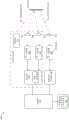
图3A示出了使用直线透镜捕获的环境的图像的表示。Figure 3A shows a representation of an image of the environment captured using a rectilinear lens.
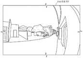
图3B示出了使用鱼眼透镜捕获的环境的图像(的一部分)的表示。Figure 3B shows a representation of an image (a portion) of the environment captured using a fisheye lens.
图3C示出了当光被直线透镜折射时,可归因于视场的中心部分的入射到传感器上的光的区域。Figure 3C shows the area of light incident on the sensor attributable to the central portion of the field of view when the light is refracted by the rectilinear lens.
图3D示出了当光被鱼眼透镜折射时,可归因于视场的中心部分的入射到传感器上的光的区域。Figure 3D shows the area of light incident on the sensor attributable to the central portion of the field of view as the light is refracted by the fisheye lens.
图4A分别示出了示例鱼眼透镜、相关联的传感器,以及透镜和传感器的相应视场的横截面。4A shows an example fisheye lens, an associated sensor, and cross-sections of the corresponding fields of view of the lens and sensor, respectively.
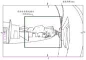
图4B示出了用鱼眼透镜拍摄的图像的表示以及该鱼眼图像的示例部分,该示例部分可以在传感器的有效视场内。4B shows a representation of an image captured with a fisheye lens and an example portion of the fisheye image, which may be within the effective field of view of the sensor.
图5示出了使用本文所述的相机系统来生成深度测量结果的示例过程的流程图。5 shows a flowchart of an example process for generating depth measurements using the camera system described herein.
具体实施方式Detailed ways
现有的深度相机技术无法产生允许使用金融级生物特征扫描和/或识别的准确性。具体地讲,现有深度相机系统使用直线透镜,使得可容易地测量像素之间的视差,这可用于确定对象的深度测量结果。此外,直线透镜的视场(FOV)倾向于最适合捕获用户的图像。例如,直线透镜传统上提供较窄的视场,因此用于捕获用户的图像。Existing depth camera technology cannot produce the accuracy that would allow the use of financial-grade biometric scanning and/or identification. Specifically, existing depth camera systems use linear lenses so that disparity between pixels can be easily measured, which can be used to determine depth measurements for objects. In addition, the field of view (FOV) of a rectilinear lens tends to be best suited for capturing the user's image. For example, linear lenses traditionally provide a narrower field of view and are therefore used to capture images of the user.
然而,与常规相反,本文所讨论的技术包括将深度感测系统的直线透镜替换为鱼眼透镜的相机系统。由于鱼眼透镜引入的畸变以及由此产生的确定深度测量结果的困难,因此先前的方法不鼓励使用鱼眼透镜。此外,鱼眼透镜提供比捕获用户图像所需的更大的视场(FOV),并且如果需要捕获鱼眼透镜的整个FOV,可能需要更高分辨率的图像传感器。However, contrary to convention, the techniques discussed herein include camera systems that replace the linear lens of the depth sensing system with a fisheye lens. Previous methods discouraged the use of fisheye lenses due to the distortion introduced by fisheye lenses and the resulting difficulties in determining depth measurements. Furthermore, fisheye lenses provide a larger field of view (FOV) than is required to capture an image of the user, and a higher resolution image sensor may be required if the entire FOV of the fisheye lens needs to be captured.
本文讨论的相机系统可以包括鱼眼透镜(和/或任何其他类型的鱼眼透镜)而不是直线透镜,以放大由相机捕获的图像的中心部分,从而改善生物特征扫描/识别和/或虹膜检测率。在一些示例中,放大图像的中心部分可增加其图像被相机系统捕获的用户的虹膜的可检测性,并且继而可以提高生物特征扫描和/或识别的准确性。The camera systems discussed herein may include a fisheye lens (and/or any other type of fisheye lens) instead of a rectilinear lens to magnify the central portion of the image captured by the camera, thereby improving biometric scanning/recognition and/or iris detection Rate. In some examples, magnifying the central portion of the image may increase the detectability of the user's iris whose image is captured by the camera system, and in turn may improve the accuracy of biometric scanning and/or recognition.
同样,与使用鱼眼透镜的通常动机相反,在一些示例中,本文讨论的相机系统可以被设计为裁剪鱼眼透镜的FOV的大部分,使得由相机系统捕获的所得图像包括鱼眼透镜的FOV的中心部分(例如40度-65度,与鱼眼透镜的FOV中典型的130度-180度相反),并裁剪投影图像的剩余可用FOV。Also, contrary to the usual motivation for using a fisheye lens, in some examples, the camera systems discussed herein can be designed to crop a substantial portion of the FOV of the fisheye lens such that the resulting image captured by the camera system includes the FOV of the fisheye lens (eg 40-65 degrees, as opposed to the typical 130-180 degrees in the FOV of a fisheye lens), and crop the remaining available FOV of the projected image.
所描述的照相机系统可以产生比现有系统更高的准确性和分辨率,同时降低假阳性率(例如,在面部识别应用的情况下成功地在双胞胎之间进行区分)。例如,通过使用鱼眼透镜(和/或另一鱼眼透镜),与利用直线透镜的相机系统相比,所述相机系统能够从更远的距离精确地检测用户的虹膜。在一些示例中,与可能需要用户将设备保持得更靠近用户的头部的采用直线透镜的一些先前的系统相反,这可允许用户将包括相机系统的设备保持在舒适的距离处,以便检测用户的虹膜。此外,与先前的深度感测相机相比,使用鱼眼透镜可允许减小图像传感器的分辨率。例如,由于鱼眼透镜在图像的中心处引入了“放大”效应,从而扩大了与用户的虹膜相关联的像素的数量,图像传感器可以具有较低分辨率,并且因此可能不需要那么多的处理能力来处理传感器的输出信号。在一些示例中,本文讨论的技术可以附加地或另选地减少获得准确和高分辨率的深度图所需的功耗和/或处理带宽的量。The described camera system can yield higher accuracy and resolution than existing systems, while reducing false positive rates (eg, successfully discriminating between twins in the case of facial recognition applications). For example, by using a fisheye lens (and/or another fisheye lens), the camera system can accurately detect a user's iris from a greater distance than a camera system utilizing a rectilinear lens. In some examples, this may allow the user to hold the device, including the camera system, at a comfortable distance in order to detect the user, as opposed to some previous systems employing a rectilinear lens that may require the user to hold the device closer to the user's head iris. Furthermore, the use of a fisheye lens may allow for a reduction in the resolution of the image sensor compared to previous depth-sensing cameras. For example, image sensors can be of lower resolution and therefore may not require as much processing as the fisheye lens introduces a "magnification" effect at the center of the image, thereby expanding the number of pixels associated with the user's iris ability to process the sensor output signal. In some examples, the techniques discussed herein may additionally or alternatively reduce the amount of power consumption and/or processing bandwidth required to obtain accurate and high-resolution depth maps.
本文所讨论的相机系统可包括一个或多个相机,其中每个相机包括至少鱼眼透镜(和/或任何其他类型的鱼眼透镜)和图像传感器。在将深度测量结果用于生物特征识别的应用中,鱼眼透镜的结合可增加虹膜检测率,并且/或者提高对象检测准确率,尤其是对于距离相机系统更远的对象而言。在一些示例中,与直线透镜和其他类似透镜相比,鱼眼透镜的结合可以导致可归因于场景(和对应图像)的中心部分的光被图像传感器的更大区域接收。因此,更多像素可以指示关于场景的中心部分的数据,在“自拍照”的情况下,该数据可以包括用户的虹膜。然而,鱼眼透镜可能引入畸变,该畸变可以导致计算深度测量结果更加困难。在一些示例中,相机系统可以包括一个或多个机器学习模型,可以对该模型进行训练以至少部分地基于地面真实深度测量结果和使用鱼眼透镜捕获的图像的训练集来计算深度测量结果。在训练之后,所得的机器学习模型可被装备为至少部分地基于从相机系统的图像传感器和透镜接收的图像来确定深度测量结果。The camera systems discussed herein may include one or more cameras, where each camera includes at least a fisheye lens (and/or any other type of fisheye lens) and an image sensor. In applications where depth measurements are used for biometric identification, the incorporation of fisheye lenses can increase iris detection rates and/or improve object detection accuracy, especially for objects that are further away from the camera system. In some examples, the combination of fisheye lenses can result in light attributable to the central portion of the scene (and corresponding image) being received by a larger area of the image sensor than rectilinear lenses and other similar lenses. Thus, more pixels may indicate data about the central portion of the scene, which in the case of a "selfie" may include the user's iris. However, fisheye lenses can introduce distortion that can make it more difficult to compute depth measurements. In some examples, the camera system can include one or more machine learning models that can be trained to compute depth measurements based at least in part on ground truth depth measurements and a training set of images captured using a fisheye lens. After training, the resulting machine learning model can be equipped to determine depth measurements based at least in part on images received from the image sensor and lens of the camera system.
在一些示例中,相机系统的图像传感器可以检测近红外或红外辐射并且/或者至少部分地基于近红外辐射和/或红外辐射来生成输出信号。但是可以设想,图像传感器可以附加地或另选地检测可见光(例如,约350纳米至约750纳米的波长)和/或其他形式的辐射。在一些情况下,控制器可以接收输出信号并且至少部分地基于输出信号来确定深度测量结果。例如,控制器可以至少部分地基于提供输出信号和/或其表示作为深度模型的输入来确定深度测量结果。深度模型可以至少部分地基于输出信号和/或其表示来输出深度测量结果。在附加或另选示例中,确定深度测量结果可以至少部分地基于计算输出信号之间的视差图。在一些示例中,深度测量结果可以用于生成环境中的一个或多个对象的三维表面的点云和/或其他表示。该表示可以被用于更准确地识别对象的位置、分类和/或部分,诸如用户的虹膜、眉毛、鼻子、嘴唇、耳朵等;吉他的指板、吉他的特定指板、吉他的弦、吉他的旋钮等;诸如此类。In some examples, the image sensor of the camera system may detect near-infrared or infrared radiation and/or generate an output signal based at least in part on the near-infrared and/or infrared radiation. It is contemplated, however, that the image sensor may additionally or alternatively detect visible light (eg, wavelengths of about 350 nanometers to about 750 nanometers) and/or other forms of radiation. In some cases, the controller may receive the output signal and determine the depth measurement based at least in part on the output signal. For example, the controller may determine the depth measurement based at least in part on providing the output signal and/or a representation thereof as input to the depth model. The depth model may output depth measurements based at least in part on the output signal and/or a representation thereof. In an additional or alternative example, determining the depth measurement may be based, at least in part, on computing a disparity map between the output signals. In some examples, the depth measurements may be used to generate point clouds and/or other representations of three-dimensional surfaces of one or more objects in the environment. This representation can be used to more accurately identify the location, classification and/or parts of objects, such as the user's iris, eyebrows, nose, lips, ears, etc.; a guitar's fretboard, a guitar's specific fretboard, a guitar's strings, a guitar's knobs, etc.; and so on.
示例场景Example scene
图1示出了示例场景100,该示例场景包括用户102(在该示例中为人类)和并入本文讨论的相机系统106的示例设备104。示例设备104被描绘为智能电话或平板电脑,但应当理解,本文所讨论的相机系统106可结合到任何设备中并且/或者可为独立设备。在所描绘的示例中,相机系统106被布置成面向“前”的配置(例如,被设计成感测示例设备104的用户的方向上的深度的“自拍”相机系统),但应当理解,相机系统106可被集成到设备的任何部分中,如深度感测的特定应用所期望的那样。FIG. 1 shows an
虽然相机系统106在图1中被描绘为包括三个元件(例如,三个相机),但应当理解,本文所讨论的相机系统106可以包括任意数量的一个或多个相机。在所描绘的示例中,感测深度的相机系统106可以包括三个相机,但是在附加或另选示例中,相机系统106可以包括两个相机,而第三相机可以为可以用于或者不可以用于深度感测的附加相机(例如,可能需要依靠附加相机进行可见光摄影,例如“自拍相机”)。在一些示例中,与用于深度感测相关联的一个(或多个)相机可以与鱼眼透镜(和/或任何其他类似的透镜)相关联。例如,图1中的示例相机系统106中所描绘的深度感测相机可从鱼眼透镜108(1)和/或鱼眼透镜108(2)接收光。例如,与附加相机相关联的图像传感器可包括比与深度相机系统的两个相机中的一个相机相关联的图像传感器更多的像素。Although the camera system 106 is depicted in FIG. 1 as including three elements (eg, three cameras), it should be understood that the camera system 106 discussed herein may include any number of one or more cameras. In the depicted example, the depth-sensing camera system 106 may include three cameras, but in additional or alternative examples, the camera system 106 may include two cameras and a third camera may or may not be used Additional camera for depth sensing (eg, it may be necessary to rely on an additional camera for visible light photography, such as a "selfie camera"). In some examples, the camera (or cameras) associated with depth sensing may be associated with a fisheye lens (and/or any other similar lens). For example, the depth-sensing camera depicted in example camera system 106 in FIG. 1 may receive light from fisheye lens 108(1) and/or fisheye lens 108(2). For example, the image sensor associated with the additional camera may include more pixels than the image sensor associated with one of the two cameras of the depth camera system.
无论配置如何,相机系统106可生成与相机系统106的视场(FOV)相关联的深度测量结果。例如,如果用户102在相机系统106的FOV内,则相机系统106可以生成与用户102和/或在FOV中的任何对象的一部分相关联的一组深度测量结果(例如,深度图)。在一些示例中,深度测量结果可表示为点云110和/或深度图,但应当理解,深度测量结果可以以许多不同形式中的任何一种形式来表示和/或存储。相机系统106可传输和/或存储深度测量结果(和/或其表示如点云)。例如,相机系统106可将深度测量结果传输至示例设备104的存储器和/或处理器,使得示例设备104(和/或未示出的设备)的处理器可以针对各种应用中的任何一种应用访问深度测量结果(例如,检测生物特征数据、面部识别、机器人控制、对象检测、对象分类)。需注意,与基于本文所讨论的技术可以生成的潜在点云相比,示出的点云110被简化。例如,对于如本文所述的用于双照相机深度系统的一对1兆像素传感器,所得的点云可以包括超过40,000个点,平均Hausdorff距离为2.10毫米或更大。这大大超过了当前的飞行时间(TOF)深度传感器,该传感器可以达到介于5,000点和10,000点之间,平均Hausdorff距离为1.8毫米。Regardless of the configuration, the camera system 106 may generate depth measurements associated with the field of view (FOV) of the camera system 106 . For example, if user 102 is within the FOV of camera system 106, camera system 106 may generate a set of depth measurements (eg, a depth map) associated with user 102 and/or a portion of any object in the FOV. In some examples, the depth measurements may be represented as a point cloud 110 and/or a depth map, although it should be understood that the depth measurements may be represented and/or stored in any of a number of different forms. Camera system 106 may transmit and/or store depth measurements (and/or representations thereof such as point clouds). For example, camera system 106 may transmit depth measurements to the memory and/or processor of
在一些示例中,本文讨论的技术导致可以允许示例设备104检测用户102的虹膜的分辨率和准确性的深度图和/或点云。检测用户的虹膜可用于生物特征认证、在面部识别应用程序中在用户之间消除歧义、跟踪视线、自动化图像上的虚拟模拟/叠加等。本文所讨论的技术相对于现有深度传感器可以提高虹膜的可检测性、虹膜检测的准确性、可检测到虹膜的距相机系统的距离和/或虹膜跟踪的应用的准确性(例如,该技术可以降低面部识别的假阳性率、提高模拟覆盖的准确性、提高视线跟踪的准确性)。In some examples, the techniques discussed herein result in a depth map and/or point cloud that may allow the
示例相机系统架构Example Camera System Architecture
图2示出了用于深度感测的示例相机系统202的架构200的框图。相机系统202是示例相机系统,其可例如用作示例设备104中的相机系统106,或者用作期望捕获深度图像的任何其他设备或系统中的相机系统。相机系统202可包括一个或多个相机,尽管图2中所示的示例为立体相机系统。第一相机可以包括与第一传感器206相关联的至少第一鱼眼透镜204(例如,和/或任何类似的透镜),并且第二相机可以包括与第二传感器210相关联的至少第二鱼眼透镜208。例如,第一鱼眼透镜204可以与第一传感器206相关联,因为第一鱼眼透镜204可以使入射在第一鱼眼透镜204上的光朝向第一传感器206折射。2 shows a block diagram of an
在一些示例中,第一鱼眼透镜204和/或第二鱼眼透镜208可具有小于180度且大于100度的窄(对于鱼眼透镜)FOV。然而,在一些示例中,第一鱼眼透镜204和/或第二鱼眼透镜208可以被设计成从180度或更大的FOV接收辐射。In some examples, the
在一些示例中,相机系统202可以附加地或另选地包括照明器212,该照明器可以向相机系统202周围和/或前方的环境发射第一类型的辐射214。辐射的“类型”可以包括波长光谱。在一些示例中,照明器212可以发射近红外和/或红外光,尽管在其他或另选示例中,照明器212可以发射任何其他波长的光。可以选择第一传感器206和/或第二传感器210以检测包括由照明器212发射的光谱的辐射。例如,照明器212可以被设计成发射近红外和/或红外辐射,并且第一传感器206和/或第二传感器210可以响应于接收到至少近红外和/或红外辐射而生成输出信号。在一些示例中,照明器212可以以诸如例如随机和/或伪随机图案的图案发射光。在一些示例中,照明器212可以将该图案传输到控制器216,控制器216可以帮助在控制器216处从第一传感器206和第二传感器210接收的图像进行立体匹配。In some examples, the camera system 202 may additionally or alternatively include an
在一些示例中,第一传感器206和/或第二传感器210可以是检测相同或不同类型的辐射的传感器。例如,第一传感器206和/或第二传感器210可以包括电光传感器,诸如例如,光电导器件、光伏器件、光电二极管和/或光电晶体管。在至少一个示例中,第一传感器206和/或第二传感器210可至少部分地基于分别入射到第一传感器206和/或第二传感器210的表面的近红外光和/或红外光来生成输出信号。在附加或另选示例中,第一传感器206和/或第二传感器210可以附加地或另选地检测可见光和/或其他波长。例如,在用于检测用户的虹膜的应用中,第一传感器206和/或第二传感器210可至少部分地基于接收到由在第一传感器206和/或第二传感器210的FOV内的环境中的对象222反射的近红外和/或红外光来生成输出信号。在一些情况下,由对象222反射的光可以包括由照明器212发射并由对象222反射的第一类型的辐射214和/或在环境中且由对象222反射的自然发生的第一类型的辐射214。In some examples, the
在一些示例中,第一传感器206和/或第二传感器210可以是裁剪传感器和/或全帧传感器。换句话说,第一传感器206可以是裁剪传感器,因为其传感器表面积小于在传感器表面处通过第一鱼眼透镜204折射的辐射的投影面积。在此类示例中,与第一鱼眼透镜204和第一传感器206相关联的第一相机可以包括一个或多个附加的光圈和/或其他装置以扩散或以其他方式散布和/或阻挡第一传感器没有接收到的辐射206。在一些示例中,第一鱼眼透镜204可以被设计成使得第一鱼眼透镜204和/或与鱼眼透镜204相关联的光圈可以将由第一传感器206感测的视场减小到小于180度。关于图3A–图4B讨论这些和其他细节。In some examples, the
相机系统202可以被配置为使得第一传感器206和/或第二传感器210将由此生成的输出信号传输至控制器216。在一些示例中,可能存在一些中间电子设备,诸如放大器、模数转换器、降噪硬件、接口(例如,总线、网络接口)等。在一些示例中,控制器216可以包括中间电子设备。无论如何,控制器216可以从第一传感器206和/或第二传感器210接收输出信号,控制器216和/或中间电子设备和/或软件可以使用这些输出信号为每个传感器生成图像和/或代表第一传感器206和/或第二传感器210的输出信号的立体图像。在一些示例中,控制器216可以包括相机控制硬件和/或软件,其可以包括用于控制与相机中的每个相机相关联的快门速度、光圈尺寸、ISO、帧速率等的硬件和/或软件(例如,与第一鱼眼透镜204和第一传感器206相关联的第一相机和与第二鱼眼透镜208和第二传感器210相关联的第二相机)。控制器216还可对相机进行协调,诸如校准相机、使相机同步(例如,定时它们各自的快门以在基本上相同的时间打开/关闭(在技术公差内)、将它们的ISO设置为相同的值)等。在一些示例中,控制器216可以接收与由照明器212投影的图案有关的数据并且/或者可以控制由照明器212投影的图案。控制器216可以使用图案数据来至少部分地基于从第一传感器206和/或第二传感器210接收的输出信号来生成立体图像,并且/或者以其他方式匹配和/或同步从第一传感器206和/或第二传感器210接收的图像。Camera system 202 may be configured such that
附加地或另选地,控制器216可以至少部分基于从第一传感器206和第二传感器210接收的输出信号来确定深度测量结果(例如,至少部分基于从第一传感器206和第二传感器210接收的图像)。在一些示例中,控制器216可以被配置为进行相机控制和校准,但是深度测量可以由在处理器218上执行的软件(例如,包括深度模型220的软件部件)来执行。在一些示例中,控制器216可以包括专用集成电路(ASIC)、现场可编程门阵列(FPGA)或其他硬件以执行深度测量。Additionally or alternatively, the
无论深度测量结果(和/或深度图)是由在处理器218上执行的软件确定的还是由控制器216的硬件确定的,通过将输出信号和/或其表示提供给深度模型220(无论深度模型220是位于处理器218可访问的存储器中、ASIC的存储器中和/或配置在ASIC或FPGA上的硬件中)并从深度模型220接收深度测量结果,可以至少部分地基于第一传感器206和第二传感器210的输出信号来生成深度测量结果。附加地或另选地,可以通过计算分别从第一传感器206和第二传感器210接收的两个图像之间的视差图来确定深度测量结果。Whether the depth measurements (and/or depth maps) are determined by software executing on the processor 218 or by hardware in the
在一些示例中,深度模型220可以包括机器学习模型,该模型可以包括但不限于神经网络(例如,仅看一次(YOLO)神经网络、VGG、DenseNet、PointNet、卷积神经网络(CNN)、堆叠式自动编码器、深度玻尔兹曼机(DBM)、深度置信网络(DBN))、回归算法(例如,普通最小二乘回归(OLSR)、线性回归、逻辑回归、逐步回归、多元自适应回归样条(MARS),局部估计散点图平滑(LOESS))、贝叶斯算法(例如,朴素贝叶斯、高斯朴素贝叶斯、多项式朴素贝叶斯、平均一依赖估计量(AODE)、贝叶斯信念网络(BNN)、贝叶斯网络)、聚类算法(例如k均值、k中位数、期望最大化(EM)、分层聚类)、关联规则学习算法(例如,感知器、反向传播、霍普菲尔德网络、径向基函数网络(RBFN))、监督学习、无监督学习、半监督学习等。神经网络架构的附加或另选示例可以包括神经网络,诸如ResNet50、ResNet101、VGG、DenseNet、PointNet等。尽管在神经网络的上下文中进行了讨论,但可根据本公开使用任何类型的机器学习。例如,机器学习算法可包括但不限于回归算法、基于实例的算法、贝叶斯算法、关联规则学习算法、深度学习算法等。In some examples, the deep model 220 may include a machine learning model, which may include, but is not limited to, a neural network (eg, Look Only Once (YOLO) Neural Network, VGG, DenseNet, PointNet, Convolutional Neural Network (CNN), Stacked Autoencoders, Deep Boltzmann Machines (DBMs), Deep Belief Networks (DBNs), regression algorithms (e.g., Ordinary Least Squares Regression (OLSR), Linear Regression, Logistic Regression, Stepwise Regression, Multivariate Adaptive Regression Splines (MARS), Local Estimation Scatterplot Smoothing (LOESS)), Bayesian Algorithms (e.g. Naive Bayes, Gaussian Naive Bayes, Multinomial Naive Bayes, Average-Dependent Estimator (AODE), Bayesian Belief Networks (BNNs, Bayesian Networks), Clustering Algorithms (e.g. k-means, k-medians, Expectation Maximization (EM), Hierarchical Clustering), Association Rule Learning Algorithms (e.g. Perceptrons) , backpropagation, Hopfield network, radial basis function network (RBFN)), supervised learning, unsupervised learning, semi-supervised learning, etc. Additional or alternative examples of neural network architectures may include neural networks such as ResNet50, ResNet101, VGG, DenseNet, PointNet, and the like. Although discussed in the context of neural networks, any type of machine learning can be used in accordance with the present disclosure. For example, machine learning algorithms may include, but are not limited to, regression algorithms, instance-based algorithms, Bayesian algorithms, association rule learning algorithms, deep learning algorithms, and the like.
深度测量可以包括从相机系统202(和/或更具体地,从第一传感器206和/或第二传感器210和/或从第一鱼眼透镜204和/或第二鱼眼透镜208)到对象222的距离的指示。在一些示例中,深度测量结果可包括到对象222上的离散位置的单个距离。在附加或另选示例中,深度测量结果可以包括一组距离(例如,深度图,可以是到环境中的不同离散点的一组距离的二维、三维等指示)和/或其表示(例如,环境中对象的点云表示,其可以从一个或多个深度图重建)。例如,深度模型220可以被训练为至少部分地基于接收从第一传感器206和/或第二传感器210接收的输出信号(和/或其表示,诸如图像和/或立体图像)作为输入来输出深度图和/或点云。在附加或另选示例中,可以至少部分地基于确定与第一传感器206的输出信号相关联的第一图像和与第二传感器206的输出信号相关联的第二图像之间的视差图来生成深度图和/或点云。Depth measurements may include from the camera system 202 (and/or more specifically, from the
在一些示例中,架构200可以包括附加相机226,其可以包括第三透镜228和第三传感器230。第三透镜228可以包括直线透镜,尽管在附加或另选示例中,第三透镜228可以包括任何类型的透镜。在一些示例中,第三传感器230可以至少部分地基于接收到第二类型的辐射232来生成输出信号。例如,第二类型的辐射232可以包括可见光波长(例如,大约350纳米至大约750纳米的波长)。在一些示例中,第三传感器230可具有比第一传感器206和/或第二传感器210更大数量的像素,尽管在附加或另选示例中,第一传感器206和/或第二传感器210可以具有与第三传感器230相同或比其更大数量的像素。例如,第三传感器230可以与主图像相机相关联。换句话说,尽管相机系统202可能主要用于生成深度测量结果(尽管在附加或另选示例中,可以显示/传输/存储供用户检索的由第一传感器206和/或第二传感器210生成的图像),第三传感器230可用于可由用户和/或应用程序显示、存储和/或检索的图像。在一些示例中,第一传感器206和第二传感器210可以具有比第三传感器228更低的分辨率。通过示例的方式并且非限制性的,第一传感器206和/或第二传感器210可以包括单色1兆像素传感器,而第三传感器228可以是彩色高分辨率传感器(例如,8兆像素传感器、10兆像素传感器、16兆像素传感器、20兆像素传感器)。可以设想的是,在此示例的变型中,第一传感器206和/或第二传感器210可以感测多于一个颜色/波长光谱,可以具有更多或更少的兆像素等。在一些示例中,图像信号处理器234可以处理与第三传感器230相关联的输出信号,这可以包括将模拟信号转换为数字信号、生成RAW文件并且/或者以其他方式生成图像以供处理器218存储和/或传输。在一些示例中,控制器216可以将控制信号传输到相机系统202的各个部分,以同步第一传感器206和/或第二传感器210捕获的图像,使其与第三传感器230捕获的图像基本上同时(在技术公差范围内)。In some examples, the
一旦确定了深度测量结果,不论深度测量结果是否由控制器216和/或处理器218确定并且/或者深度测量结果是否包括单个/多个距离、深度图、点云和/或深度测量结果的一些其他表示,深度测量结果都可以存储在存储器224中、传输到另一设备并且/或者由运行在处理器218上的应用程序236使用以完成任务(例如,应用程序236可以包括一项任务,该任务包括机器人控制、面部识别、生物特征检测/聚合、虚拟/增强现实模拟、图像叠加/编辑、背景替换等)。在一些示例中,处理器218可以将深度测量结果与与第三传感器228相关联地生成的图像相关联。例如,处理器218可以将由图像信号处理器234生成的与深度图相关联的图像存储在存储器224中,应用程序236可以使用该图像和/或深度测量结果来完成任务(例如,验证用户的身份、编辑图像、对用户的图像进行过度虚拟现实模拟、删除图像的背景部分)等。Once the depth measurement is determined, whether the depth measurement is determined by the
在一些示例中,处理器218可以校正由第一传感器206和/或第二传感器210生成的图像。例如,校正图像可以包括通过重新映射、翘曲和/或以其他方式将图像重新投影成直线投影图像的模仿来“去除”图像。在一些示例中,处理器218可以这样做以将图像的一部分与由第三传感器228生成的直线图像对准和/或匹配。In some examples, the processor 218 may correct images generated by the
在一些示例中,处理器218可以是能够执行指令以处理数据并执行如本文所述的操作的任何合适的处理器。通过示例的方式并且非限制性的,处理器218可以包括一个或多个中央处理单元(CPU)、图形处理单元(GPU)、集成电路(例如,专用集成电路(ASIC)等)、门阵列(例如,现场可编程门阵列(FPGA)等)、应用处理器、和/或处理电子数据以将该电子数据转换为可以存储在寄存器和/或存储器中的其他电子数据的任何其他设备或设备的一部分。例如,在相机系统202被集成到智能电话和/或平板设备中的情况下,处理器218可以包括至少一个应用处理器。In some examples, processor 218 may be any suitable processor capable of executing instructions to process data and perform operations as described herein. By way of example and not limitation, processor 218 may include one or more central processing units (CPUs), graphics processing units (GPUs), integrated circuits (eg, application specific integrated circuits (ASICs), etc.), gate arrays ( For example, a field programmable gate array (FPGA), etc.), an application processor, and/or any other device or device that processes electronic data to convert that electronic data into other electronic data that can be stored in registers and/or memory part. For example, where camera system 202 is integrated into a smartphone and/or tablet device, processor 218 may include at least one applications processor.
在一些示例中,存储器224可以是非暂态计算机可读介质的示例。存储器224可以存储操作系统和一个或多个软件应用程序、指令、程序和/或数据,以实现本文描述的方法以及归因于各种系统的功能。在各种具体实施中,可以使用任何合适的存储器技术来实现该存储器,诸如静态随机存取存储器(SRAM)、同步动态RAM(SDRAM)、非易失性/闪存类型的存储器,或者能够存储信息的任何其他类型的存储器。本文描述的架构、系统和单个元件可以包括许多其他逻辑、程序和物理部件,附图中示出的那些仅仅是与本文的讨论有关的示例。In some examples, memory 224 may be an example of a non-transitory computer-readable medium. Memory 224 may store an operating system and one or more software applications, instructions, programs, and/or data to implement the methods described herein and the functions attributed to the various systems. In various implementations, the memory may be implemented using any suitable memory technology, such as static random access memory (SRAM), synchronous dynamic RAM (SDRAM), non-volatile/flash type memory, or capable of storing information any other type of memory. The architectures, systems and individual elements described herein may include many other logical, procedural and physical components, those shown in the figures are merely examples relevant to the discussions herein.
在一些示例中,深度模型220可以存储在存储器224上,并由运行在处理器218上的应用程序236执行。在附加或另选示例中,深度模型220可被配置在控制器216上。例如,深度模型220可以被配置为控制器216的硬件部分,并且/或者深度模型220可以包括存储在与控制器216相关联的ASIC的存储器中的神经网络权重。在一些示例中,控制器216可以执行即时加密以加密与深度模型220相关联的权重,而无论与深度模型220相关联的机器学习模型的类型如何。In some examples, depth model 220 may be stored on memory 224 and executed by
示例图像example image
图3A示出了用直线透镜拍摄的图像(“直线图像300”)的表示,而图3B示出了用鱼眼透镜拍摄的图像(“鱼眼图像302”)(的一部分)的表示。值得注意的是,直线透镜使光折射,使得距离图像中心较远的对象与位于图像中心的对象相比显得“拉伸”。这是由于此类透镜的透视投影。在功能上,这意味着光在直线透镜上的入射角越大,折射角相同增加,导致遍历光将被折射到的传感器上的像素的数量更多(即,距传感器平面上光学中心的距离与入射角的切线成正比)。通过缩小图像的中心可以补偿这种“拉伸”,从而导致图像的中心看起来更小。此外,直线透镜的FOV越大,为了适应透镜的FOV中心需要缩小的越多。应当注意,图像中心的这种缩小导致“正常”外观的图像,如直线图像300所示,并且还减小了图像中心处的对象的表观尺寸。例如,将直线图像300中心的货车的表观尺寸与鱼眼图像302中心的货车的表观尺寸进行比较。Figure 3A shows a representation of an image captured with a rectilinear lens ("
然而,鱼眼透镜可以被设计成折射光,使得FOV中的对象的比例可以与鱼眼透镜上的光的入射角成正比。换句话说,入射角的相同增加将引起传感器与折射射线之间的交点的光轴的距离的相同增加。距传感器上的光轴的距离d对鱼眼透镜的入射角α的依赖性可以表示为d=kα。如在鱼眼图像302中可见,这导致朝向图像的边缘的畸变并且放大了图像的中心,并且与直线透镜相比,还使得鱼眼透镜能够折射从实质上更高的FOV接收的光。这促使将鱼眼透镜用作广角透镜以与可被直线透镜捕获的图像的量相比捕获图像中的更多环境。例如,鱼眼透镜的FOV可以介于100度和270度之间,而FOV介于160度和180度之间更为常见,而直线透镜具有变化很大的FOV,这取决于系统的焦距,但是一般的应用通常具有不超过80度的FOV,并且经常介于10度和60度之间。例如,对于直线透镜,距传感器上的光轴的距离d对入射角α的依赖性可以表示为d=ktan(α)。然而,如下面更详细地讨论的,与常规用途相反,鱼眼透镜被用于产生窄FOV。However, the fisheye lens can be designed to refract light so that the proportion of objects in the FOV can be proportional to the angle of incidence of the light on the fisheye lens. In other words, the same increase in the angle of incidence will cause the same increase in the distance of the optical axis of the intersection between the sensor and the refracted ray. The dependence of the distance d from the optical axis on the sensor on the angle of incidence α of the fisheye lens can be expressed as d=kα. As can be seen in fisheye image 302, this results in distortion towards the edges of the image and magnifies the center of the image, and also enables the fisheye lens to refract light received from a substantially higher FOV compared to a rectilinear lens. This motivates the use of a fisheye lens as a wide-angle lens to capture more of the environment in an image than can be captured by a rectilinear lens. For example, fisheye lenses can have FOVs between 100 and 270 degrees, while FOVs between 160 and 180 degrees are more common, while linear lenses have FOVs that vary widely, depending on the focal length of the system, But general applications typically have an FOV of no more than 80 degrees, and often between 10 and 60 degrees. For example, for a linear lens, the dependence of the distance d from the optical axis on the sensor on the angle of incidence α can be expressed as d=ktan(α). However, as discussed in more detail below, in contrast to conventional use, fisheye lenses are used to create narrow FOVs.
图3C和图3D对比了使用直角透镜与使用鱼眼透镜的归因于FOV中心的光入射到传感器的区域。图3C和3D均示出了在直线图像300和鱼眼图像302中描绘的环境304的表示以及对透镜可见的环境304的FOV的中心部分306。图3C示意性地表示通过直线透镜(为简化起见未示出)可归因于中心部分306的光到传感器308的折射,并且图3D示意性地表示通过鱼眼透镜(为简化起见未示出)可归因于中心部分306的光到传感器308的折射。传感器308以横截面的方式示出,并且投影在其上的光的区域一维地示出。传感器308可以表示第一传感器206和/或第二传感器210。通过直线透镜归因于中心部分306的光的折射入射在传感器308的区域310上,而通过鱼眼透镜归因于中心部分306的光的折射入射在传感器308的区域312上。如图3C和3D中示意性示出的,区域312大于区域310。鱼眼透镜的使用导致畸变,在压缩FOV的边的同时会稍微放大FOV的中心,而直线透镜则具有相反的效果。如图3D所示,由相机使用鱼眼透镜产生的图像与由相机使用直线透镜产生的图像相比,将包括与中心部分306相关联的更多数量的像素(更高的分辨率)。在一些示例中,由相机使用鱼眼透镜生成的图像将包括可归因于用户面部特征(例如,虹膜、眼睛、眉毛、鼻子、嘴巴)的附加像素,因为至少在一些情况下,用户倾向于集中在图像(尤其是自拍)上。鱼眼透镜的使用可以因此增加归因于面部特征的像素的数量,并且因此可以提高生物特征扫描和/或识别的准确性。Figures 3C and 3D compare the area of light impinging on the sensor attributed to the center of the FOV using a right angle lens versus using a fisheye lens. 3C and 3D both show representations of the environment 304 depicted in the
示例架构Example schema
图4A示出了根据以上讨论的相机系统202的鱼眼透镜402和传感器404的架构400的横截面。鱼眼透镜402可以表示鱼眼透镜204和/或鱼眼透镜208,并且传感器404可以表示第一传感器206和/或第二传感器210。根据本文讨论的技术,本文讨论的技术可以包括将鱼眼透镜402用作窄FOV透镜,而不是将鱼眼透镜402用作广角透镜以捕获更多环境的图像。例如,采用鱼眼透镜402可以包括:调节鱼眼透镜402中的一个或多个透镜的曲率以减小FOV,调节鱼眼透镜402与传感器404的间距,并且/或者借助本文讨论的架构400裁剪鱼眼透镜402的FOV的大部分。尽管这些方法中的一者或多者可用于放大FOV的中心,同时减小所得图像的有效FOV,但架构400是至少部分地基于修剪和/或传感器透镜间距来缩小FOV的示例。4A shows a cross-section of the
通过使用鱼眼透镜402并且捕获小于鱼眼透镜402的整个FOV的图像,深度模型220可以产生更准确的和/或详细的深度测量结果。此外,在面部识别和生物特征使用情况下,架构400可增加检测用户的虹膜的可能性和/或准确性和/或虹膜距仍然可检测到虹膜的架构400的距离,这是由于传感器404捕获的图像的中心未压缩。By using
在所描绘的示例中,鱼眼透镜402被设计成具有180度的FOV(“透镜视场406”)。需注意,为了讨论起见,尽管FOV可沿不同的轴线变化(例如,垂直FOV可不同于水平FOV),但为了简单起见,我们假定FOV在水平和垂直方向上均为180度,但在附加或另选示例中,鱼眼透镜402可被设计成沿透镜的不同轴线具有不同的FOV。此外,对于本文讨论的技术,可以基于集成相机系统202的设备和/或用途来调整鱼眼透镜402的FOV。虽然本文中讨论为鱼眼透镜,但可使用放大所得图像的中心部分的任何透镜。In the depicted example,
鱼眼透镜402(和/或其他附带的透镜)可以被设计成使入射在鱼眼透镜402的外表面上的光朝向传感器404折射。在一些示例中,传感器404可以被设计成至少部分地基于入射在传感器404的暴露表面408上的光来生成输出信号。根据本文讨论的技术,暴露表面408的表面积可以小于通过鱼眼透镜402朝向传感器404折射的光的投影面积410。因此,传感器404具有小于透镜视场406的有效视场412。The fisheye lens 402 (and/or other accompanying lenses) may be designed to refract light incident on the outer surface of the
在一些示例中,传感器404的暴露表面408的尺寸和/或投影区域410的尺寸可以被设计成使得传感器404具有介于40度和60度之间的有效FOV412。对于具有180度的FOV的鱼眼透镜402,架构400在FOV的120度与140度之间进行裁剪。透镜FOV 406被裁剪的量取决于相机系统结合在其中的设备和/或相机系统202的用途。有效传感器视场412可取决于对象距相机系统的预期距离。例如,传感器404的放置和尺寸可以被设计成使得预期对象越远,有效传感器视场412越窄。为了说明,为了将相机系统202集成到作为前置系统的智能电话中,有效传感器FOV 412可以是60度,而作为面向环境的相机,有效传感器FOV 412可以是40度。In some examples, the size of the exposed surface 408 of the sensor 404 and/or the size of the projection area 410 may be designed such that the sensor 404 has an effective FOV 412 of between 40 and 60 degrees. For a
图4B示出了用鱼眼透镜拍摄的图像(鱼眼图像302)(的一部分)和鱼眼图像302的示例部分414的表示,该示例部分414可以在传感器404的有效FOV 412内。示例部分414没有按比例绘制,鱼眼图像302也不包括整个180度FOV,但是示例部分414部分地示出了由本文讨论的架构400实现的FOV的大幅减小。FIG. 4B shows an image captured with a fisheye lens (a portion of fisheye image 302 ) and a representation of an example portion 414 of fisheye image 302 that may be within effective FOV 412 of sensor 404 . The example portion 414 is not drawn to scale and the fisheye image 302 does not include the entire 180 degree FOV, but the example portion 414 partially illustrates the substantial reduction in FOV achieved by the
示例过程Example process
图5示出了用于使用本文描述的相机系统生成深度测量结果的示例过程500的流程图。在一些示例中,示例过程500可以由本文讨论的相机系统202来实现。5 shows a flowchart of an
在操作502(1)和/或502(2)处,示例过程500可以包括根据本文讨论的任何技术在图像传感器处经由鱼眼透镜接收辐射。例如,两个传感器可以从相同和/或不同的鱼眼透镜接收辐射。在一些示例中,传感器接收到的辐射可以包括在相机系统周围的环境中自然可用的近红外和/或红外光以及/或者由相机系统的发射器发射到环境中引入的近红外和/或红外光。At operations 502(1) and/or 502(2),
在操作504(1)和/或504(2)处,示例过程500可以包括根据本文讨论的任何技术,至少部分地基于辐射由图像传感器来生成输出信号。例如,传感器可以被配置为输出指示入射在传感器上的光的输出信号。在一些示例中,输出信号可以包括电压、量值、电流和/或与一个或多个像素相关联的量值的其他指示。At operations 504(1) and/or 504(2), the
在操作506处,示例过程500可以包括根据本文讨论的任何技术,至少部分地基于第一输出信号和/或第二输出信号来确定深度测量结果。在一些示例中,相机系统202可以包括两个相机/传感器对。在此类示例中,深度测量结果可以由深度模型至少部分地基于由传感器对生成的第一输出信号和/或第二输出信号来生成。在一些示例中,使用深度模型生成深度测量结果可以包括提供第一输出信号、第二输出信号和/或其表示作为机器学习模型的输入,并且从机器学习模型且响应于该规定接收深度测量结果。At operation 506, the
示例性条款Exemplary Terms
A.一种系统,该系统包括:照明器,该照明器被配置为发射第一类型的辐射;鱼眼透镜;第一图像传感器,该第一图像传感器被配置为至少部分地基于经由鱼眼透镜接收第一光来生成第一输出信号,该第一光包括第一类型的辐射;第二图像传感器,该第二图像传感器被配置为至少部分地基于经由第二透镜接收第二光来生成第二输出信号,该第二光包括第一类型的辐射或第二类型的辐射中的至少一者;以及控制器,该控制器可操作地连接到第一图像传感器和第二图像传感器,并且被配置为至少部分地基于第一输出信号来生成在第一图像传感器和第二图像传感器的视场中可见的环境的深度图。A. A system comprising: an illuminator configured to emit radiation of a first type; a fisheye lens; a first image sensor configured to be based at least in part on via the fisheye a lens receives first light to generate a first output signal, the first light including a first type of radiation; a second image sensor configured to generate based at least in part on receiving the second light via the second lens a second output signal, the second light including at least one of the first type of radiation or the second type of radiation; and a controller operably connected to the first image sensor and the second image sensor, and is configured to generate a depth map of the environment visible in the fields of view of the first image sensor and the second image sensor based at least in part on the first output signal.
B.根据段落A所述的系统,其中,第一图像传感器的第一视场和第二图像传感器的第二视场重叠。B. The system of paragraph A, wherein the first field of view of the first image sensor and the second field of view of the second image sensor overlap.
C.根据段落A或B所述的系统,其中,生成深度图包括:提供第一输入信号或第一输入信号的表示中的至少一者作为机器学习模型的输入;以及从机器学习模型接收深度图。C. The system of paragraph A or B, wherein generating the depth map comprises: providing at least one of the first input signal or a representation of the first input signal as an input to the machine learning model; and receiving the depth from the machine learning model picture.
D.根据段落A至C中任一项所述的系统,其中,第一类型的辐射包括红外光或近红外光,并且第二类型的辐射包括可见光。D. The system of any of paragraphs A-C, wherein the first type of radiation includes infrared light or near-infrared light, and the second type of radiation includes visible light.
E.根据段落A至D中任一项所述的系统,其中,第一图像传感器包括单色红外传感器或单色近红外传感器中的至少一者。E. The system of any of paragraphs A-D, wherein the first image sensor comprises at least one of a monochromatic infrared sensor or a monochromatic near-infrared sensor.
F.根据段落A至E中任一项所述的系统,其中:控制器包括处理器;并且生成深度图至少部分基于执行存储在存储器中的指令的处理器,存储在存储器中的指令包括神经网络的一个或多个权重。F. The system of any of paragraphs A through E, wherein: the controller includes a processor; and generating the depth map is based at least in part on a processor executing instructions stored in a memory, the instructions stored in the memory including a neural One or more weights for the network.
G.根据段落A至F中任一项所述的系统,其中,控制器包括专用集成电路(ASIC)或现场可编程门阵列(FPGA)。G. The system of any of paragraphs A to F, wherein the controller comprises an application specific integrated circuit (ASIC) or a field programmable gate array (FPGA).
H.一种设备,该设备包括:第一曲线透镜;第一图像传感器,该第一图像传感器被配置为响应于经由第一曲线透镜接收第一辐射而生成第一输出信号;以及包括深度模型的控制器,该控制器被配置为:接收第一输出信号作为输入;并且至少部分地基于第一输出信号来输出深度测量结果。H. An apparatus comprising: a first curvilinear lens; a first image sensor configured to generate a first output signal in response to receiving first radiation via the first curvilinear lens; and including a depth model The controller is configured to: receive a first output signal as an input; and output a depth measurement based at least in part on the first output signal.
I.根据段落H所述的设备,其中:控制器包括应用处理器;并且深度模型由应用处理器执行。I. The apparatus of paragraph H, wherein: the controller includes an application processor; and the depth model is executed by the application processor.
J.根据段落H或I所述的设备,其中:控制器包括专用集成电路(ASIC)或现场可编程门阵列(FPGA);并且ASIC被配置为存储或执行深度模型中的至少一者。J. The apparatus of paragraph H or I, wherein: the controller comprises an application specific integrated circuit (ASIC) or a field programmable gate array (FPGA); and the ASIC is configured to at least one of store or execute the depth model.
K.根据段落H至J中任一项所述的设备,还包括被配置为发出第一类型的辐射的照明器,并且其中,第一辐射和第二辐射具有第一类型,并且包括响应于由照明器发出的辐射而从对象反射的辐射。K. The apparatus of any of paragraphs H to J, further comprising an illuminator configured to emit a first type of radiation, and wherein the first radiation and the second radiation are of the first type, and comprising a response to Radiation reflected from an object by radiation emitted by an illuminator.
L.根据段落H至K中任一项所述的设备,其中,第一类型包括红外光或近红外光中的至少一者。L. The apparatus of any of paragraphs H-K, wherein the first type includes at least one of infrared light or near-infrared light.
M.根据段落H至L中任一项所述的设备,还包括第二透镜和第二传感器,其中:第二传感器被配置为至少部分基于经由第二透镜接收第二辐射来生成第二输出信号,第二辐射是不同于第一类型的第二类型的辐射。M. The apparatus of any of paragraphs H to L, further comprising a second lens and a second sensor, wherein the second sensor is configured to generate a second output based at least in part on receiving the second radiation via the second lens The signal, the second radiation is a second type of radiation different from the first type.
N.根据段落H至M中任一项所述的设备,其中与第一图像传感器相关联的视场小于或等于BM度。N. The apparatus of any of paragraphs H to M, wherein the field of view associated with the first image sensor is less than or equal to BM degrees.
O.一种方法,包括:在第一图像传感器处经由第一曲线透镜接收第一辐射;在第二图像传感器处,经由第二曲线透镜接收第二辐射;第一图像传感器至少部分地基于第一辐射生成第一输出信号;第二图像传感器至少部分地基于第二辐射生成第二输出信号;以及至少部分地基于第一输出信号和第二输出信号来确定深度测量结果。O. A method comprising: receiving, at a first image sensor, first radiation via a first curved lens; at a second image sensor, receiving second radiation via a second curved lens; the first image sensor based at least in part on a A radiation generates a first output signal; a second image sensor generates a second output signal based at least in part on the second radiation; and determines a depth measurement based at least in part on the first output signal and the second output signal.
P.根据段落O所述的方法,其中,确定深度测量结果至少部分基于:提供第一输出信号和第二信号或其表示作为深度模型的输入;以及从深度模型接收深度测量结果。P. The method of
Q.根据段落O或P所述的方法,其中,确定深度测量结果至少部分地基于确定第一输出信号与第二输出信号之间的差异。Q. The method of paragraph O or P, wherein determining the depth measurement is based at least in part on determining a difference between the first output signal and the second output signal.
R.根据段落O至Q中任一项所述的方法,其中,第一辐射和第二辐射包括红外光或近红外光中的至少一者。R. The method of any of paragraphs O to Q, wherein the first radiation and the second radiation comprise at least one of infrared light or near infrared light.
S.根据段落O至R中任一项所述的方法,还包括:在第三图像传感器处,经由透镜接收第三辐射;由第三图像传感器至少部分地基于第三辐射来生成第三输出信号;以及至少部分地基于第三输出信号来引起图像的显示或存储中的至少一者。S. The method of any of paragraphs O to R, further comprising: at a third image sensor, receiving third radiation via a lens; generating, by the third image sensor, a third output based at least in part on the third radiation a signal; and causing at least one of display or storage of an image based at least in part on the third output signal.
T.根据段落O至S中任一项所述的方法,还包括:由照明器发射辐射,其中:至少部分地基于对象对辐射的反射来接收第一辐射和第二辐射;以及深度测量结果包括从对象到第一图像传感器或第二图像传感器中的至少一者的距离。T. The method of any of paragraphs O to S, further comprising: emitting, by the illuminator, radiation, wherein: the first radiation and the second radiation are received based at least in part on reflection of the radiation by the object; and a depth measurement A distance from the object to at least one of the first image sensor or the second image sensor is included.
尽管已经用特定于结构特征和/或方法动作的语言描述了主题,但是应该理解,所附权利要求书中限定的主题不一定限于所描述的特定特征或动作。相反,将特定特征和动作公开为实现权利要求的示例形式。Although the subject matter has been described in language specific to structural features and/or methodological acts, it is to be understood that the subject matter defined in the appended claims is not necessarily limited to the specific features or acts described. Rather, the specific features and acts are disclosed as example forms of implementing the claims.
本文所述的部件表示可存储在任何类型的计算机可读介质中并且可在软件和/或硬件中实现的指令。上述所有方法和过程均可通过由一个或多个计算机或处理器,硬件或它们的一些组合执行的软件代码部件和/或计算机可执行指令来体现,并且完全自动化。这些方法中的一些或全部可以另选地体现在专用计算机硬件中。The components described herein represent instructions that may be stored in any type of computer-readable medium and that may be implemented in software and/or hardware. All of the methods and processes described above may be embodied by software code components and/or computer-executable instructions executed by one or more computers or processors, hardware, or some combination thereof, and be fully automated. Some or all of these methods may alternatively be embodied in dedicated computer hardware.
除非另有明确说明,否则条件语言(诸如“可以”,“可能”,“可”或“可能”)在上下文中应理解为表示某些示例包括而其他示例不包括的某些特征、元素和/或步骤。因此,此类条件语言通常不旨在暗示一个或多个示例以任何方式需要某些特征、元素和/或步骤,或者一个或多个示例必然包括用于在有或没有用户输入或提示的情况下确定在任何特定示例中是否包括或将要执行某些特征、元素和/或步骤的逻辑。Unless expressly stated otherwise, conditional language (such as "may", "may", "may" or "may") should be understood in context to mean certain features, elements, and / or steps. Thus, such conditional language is generally not intended to imply that one or more examples require certain features, elements, and/or steps in any way, or that one or more examples are necessarily included for use with or without user input or prompting Logic that determines whether certain features, elements, and/or steps are included or to be performed in any particular example.
除非另有明确说明,否则诸如短语“X,Y或Z中的至少一者”的组合语应理解为表示项、术语等可以是X、Y或Z或其任何组合,包括每个元素的倍数。除非明确描述为单数,否则“a”表示单数和复数。Unless expressly stated otherwise, combinations such as the phrase "at least one of X, Y, or Z" should be understood to mean that the item, term, etc. can be X, Y, or Z, or any combination thereof, including multiples of each element . "a" means both singular and plural unless explicitly described as singular.
本文描述的和/或在附图中描绘的流程图中的任何常规描述、元素或框都应理解为潜在地表示模块、代码段或代码的一部分,包括用于在例程中实现特定逻辑功能或元素的一个或多个计算机可执行指令。另选实施方案包括在本文描述的示例的范围内,其中取决于所涉及的功能,如本领域技术人员将理解的那样,元素或功能可能会从所示或所讨论的元素或功能中删除或乱序执行,包括基本上同步、相反顺序、使用其他操作或省略操作。Any conventional descriptions, elements or blocks in the flowcharts described herein and/or depicted in the figures should be understood to potentially represent modules, code segments, or portions of code, including for implementing specified logical functions in the routines or one or more computer-executable instructions of an element. Alternative embodiments are included within the scope of the examples described herein, in which elements or functions may be omitted from those shown or discussed, as will be understood by those skilled in the art, depending on the functionality involved. Out-of-order execution, including substantially synchronization, reverse order, use of other operations, or omission of operations.
可对上述示例进行许多变型和修改,这些示例的元素将被理解为是其他可接受的示例中的元素。所有此类修改形式和变型形式旨在被包括在本公开的范围内并且受以下权利要求书保护。Many variations and modifications are possible to the above-described examples, and elements of these examples are to be understood as elements of other acceptable examples. All such modifications and variations are intended to be included within the scope of this disclosure and protected by the following claims.
Claims (20)
Applications Claiming Priority (4)
| Application Number | Priority Date | Filing Date | Title |
|---|---|---|---|
| US201862775525P | 2018-12-05 | 2018-12-05 | |
| US62/775,525 | 2018-12-05 | ||
| US16/389,895 | 2019-04-19 | ||
| US16/389,895US11902496B2 (en) | 2018-12-05 | 2019-04-19 | Depth sensing camera system |
Publications (2)
| Publication Number | Publication Date |
|---|---|
| CN111272144Atrue CN111272144A (en) | 2020-06-12 |
| CN111272144B CN111272144B (en) | 2024-06-21 |
Family
ID=70972617
Family Applications (1)
| Application Number | Title | Priority Date | Filing Date |
|---|---|---|---|
| CN201911228518.XAActiveCN111272144B (en) | 2018-12-05 | 2019-12-04 | Depth Sensing Camera System |
Country Status (2)
| Country | Link |
|---|---|
| US (1) | US11902496B2 (en) |
| CN (1) | CN111272144B (en) |
Families Citing this family (5)
| Publication number | Priority date | Publication date | Assignee | Title |
|---|---|---|---|---|
| CN113424524B (en)* | 2019-03-27 | 2023-02-14 | Oppo广东移动通信有限公司 | Three-dimensional modeling using hemispherical or spherical visible depth images |
| US11308618B2 (en) | 2019-04-14 | 2022-04-19 | Holovisions LLC | Healthy-Selfie(TM): a portable phone-moving device for telemedicine imaging using a mobile phone |
| US12014500B2 (en) | 2019-04-14 | 2024-06-18 | Holovisions LLC | Healthy-Selfie(TM): methods for remote medical imaging using a conventional smart phone or augmented reality eyewear |
| US12416729B2 (en)* | 2020-08-13 | 2025-09-16 | Artilux, Inc. | System and method for improving 3D sensor measurement accuracy |
| US20220270349A1 (en)* | 2021-02-25 | 2022-08-25 | Canon Kabushiki Kaisha | Information processing apparatus, information processing method, and program |
Citations (4)
| Publication number | Priority date | Publication date | Assignee | Title |
|---|---|---|---|---|
| US20050111696A1 (en)* | 2003-11-24 | 2005-05-26 | Baer Richard L. | Imaging surveillance system and method for event detection in low illumination |
| CN102197415A (en)* | 2008-10-21 | 2011-09-21 | 皇家飞利浦电子股份有限公司 | Method and device for providing a layered depth model of a scene |
| WO2018037789A1 (en)* | 2016-08-22 | 2018-03-01 | ソニー株式会社 | Image processing device, image processing method, and program |
| US20180130255A1 (en)* | 2016-11-04 | 2018-05-10 | Aquifi, Inc. | System and method for portable active 3d scanning |
Family Cites Families (5)
| Publication number | Priority date | Publication date | Assignee | Title |
|---|---|---|---|---|
| JP2005134867A (en)* | 2003-10-08 | 2005-05-26 | Nikon Corp | Image display device |
| US8248499B2 (en)* | 2009-02-23 | 2012-08-21 | Gary Edwin Sutton | Curvilinear sensor system |
| AU2013206685A1 (en)* | 2013-07-04 | 2015-01-22 | Canon Kabushiki Kaisha | Projected user interface system for multiple users |
| US9609307B1 (en)* | 2015-09-17 | 2017-03-28 | Legend3D, Inc. | Method of converting 2D video to 3D video using machine learning |
| US11182917B2 (en)* | 2017-12-08 | 2021-11-23 | Baidu Usa Llc | Stereo camera depth determination using hardware accelerator |
- 2019
- 2019-04-19USUS16/389,895patent/US11902496B2/enactiveActive
- 2019-12-04CNCN201911228518.XApatent/CN111272144B/enactiveActive
Patent Citations (4)
| Publication number | Priority date | Publication date | Assignee | Title |
|---|---|---|---|---|
| US20050111696A1 (en)* | 2003-11-24 | 2005-05-26 | Baer Richard L. | Imaging surveillance system and method for event detection in low illumination |
| CN102197415A (en)* | 2008-10-21 | 2011-09-21 | 皇家飞利浦电子股份有限公司 | Method and device for providing a layered depth model of a scene |
| WO2018037789A1 (en)* | 2016-08-22 | 2018-03-01 | ソニー株式会社 | Image processing device, image processing method, and program |
| US20180130255A1 (en)* | 2016-11-04 | 2018-05-10 | Aquifi, Inc. | System and method for portable active 3d scanning |
Non-Patent Citations (1)
| Title |
|---|
| MATTEO POGGI 等: "Efficient Confidence Measures for Embedded"* |
Also Published As
| Publication number | Publication date |
|---|---|
| US20200186782A1 (en) | 2020-06-11 |
| US11902496B2 (en) | 2024-02-13 |
| CN111272144B (en) | 2024-06-21 |
Similar Documents
| Publication | Publication Date | Title |
|---|---|---|
| CN111272144B (en) | Depth Sensing Camera System | |
| JP7723808B2 (en) | Image processing device and image processing method | |
| US11747898B2 (en) | Method and apparatus with gaze estimation | |
| US10713814B2 (en) | Eye tracking method and system | |
| US9600714B2 (en) | Apparatus and method for calculating three dimensional (3D) positions of feature points | |
| US10866635B2 (en) | Systems and methods for capturing training data for a gaze estimation model | |
| US10452958B2 (en) | System and method for image comparison based on hyperplanes similarity | |
| JP2020042503A (en) | 3D representation generation system | |
| US20230171492A1 (en) | Autofocus imaging circuitry, autofocus imaging apparatus, and autofocus imaging method for an event camera | |
| CN106537217A (en) | Wide field-of-view depth imaging | |
| CN108111768A (en) | Method and device for controlling focusing, electronic equipment and computer readable storage medium | |
| Bermejo et al. | FacialSCDnet: A deep learning approach for the estimation of subject-to-camera distance in facial photographs | |
| CN114049250B (en) | Method, device and medium for correcting face pose of certificate photo | |
| US20230222727A1 (en) | Method and device for generating three-dimensional image by using plurality of cameras | |
| US20230064329A1 (en) | Identification model generation apparatus, identification apparatus, identification model generation method, identification method, and storage medium | |
| JP2018081378A (en) | Image processing apparatus, imaging device, image processing method, and image processing program | |
| JP2018133064A (en) | Image processing apparatus, imaging apparatus, image processing method, and image processing program | |
| US20240147065A1 (en) | Method and apparatus with autofocus | |
| US12423934B2 (en) | Image processing apparatus, image processing method, and storage medium | |
| US20240054668A1 (en) | Image processing apparatus, image processing method, and storage medium | |
| Lu et al. | Unstructured Multi-view Stereo Anomaly Detection | |
| CN111553286A (en) | Method and electronic device for capturing ear animation characteristics | |
| Lin et al. | Subpixel Catadioptric Modeling of High Resolution Corneal Reflections. | |
| CN116958224A (en) | Depth prediction method, device, equipment and storage medium | |
| CN117173388A (en) | Methods for estimating the three-dimensional position of an object |
Legal Events
| Date | Code | Title | Description |
|---|---|---|---|
| PB01 | Publication | ||
| PB01 | Publication | ||
| SE01 | Entry into force of request for substantive examination | ||
| SE01 | Entry into force of request for substantive examination | ||
| GR01 | Patent grant | ||
| GR01 | Patent grant |