CN111267073B - Industrial robot teaching system and method based on augmented reality technology - Google Patents
Industrial robot teaching system and method based on augmented reality technologyDownload PDFInfo
- Publication number
- CN111267073B CN111267073BCN202010211069.4ACN202010211069ACN111267073BCN 111267073 BCN111267073 BCN 111267073BCN 202010211069 ACN202010211069 ACN 202010211069ACN 111267073 BCN111267073 BCN 111267073B
- Authority
- CN
- China
- Prior art keywords
- robot
- physical
- teaching
- unit
- computer
- Prior art date
- Legal status (The legal status is an assumption and is not a legal conclusion. Google has not performed a legal analysis and makes no representation as to the accuracy of the status listed.)
- Active
Links
Images

Classifications
- B—PERFORMING OPERATIONS; TRANSPORTING
- B25—HAND TOOLS; PORTABLE POWER-DRIVEN TOOLS; MANIPULATORS
- B25J—MANIPULATORS; CHAMBERS PROVIDED WITH MANIPULATION DEVICES
- B25J9/00—Programme-controlled manipulators
- B25J9/0081—Programme-controlled manipulators with leader teach-in means
- B—PERFORMING OPERATIONS; TRANSPORTING
- B25—HAND TOOLS; PORTABLE POWER-DRIVEN TOOLS; MANIPULATORS
- B25J—MANIPULATORS; CHAMBERS PROVIDED WITH MANIPULATION DEVICES
- B25J9/00—Programme-controlled manipulators
- B25J9/02—Programme-controlled manipulators characterised by movement of the arms, e.g. cartesian coordinate type
- B25J9/023—Cartesian coordinate type
- B—PERFORMING OPERATIONS; TRANSPORTING
- B25—HAND TOOLS; PORTABLE POWER-DRIVEN TOOLS; MANIPULATORS
- B25J—MANIPULATORS; CHAMBERS PROVIDED WITH MANIPULATION DEVICES
- B25J9/00—Programme-controlled manipulators
- B25J9/08—Programme-controlled manipulators characterised by modular constructions
- B—PERFORMING OPERATIONS; TRANSPORTING
- B25—HAND TOOLS; PORTABLE POWER-DRIVEN TOOLS; MANIPULATORS
- B25J—MANIPULATORS; CHAMBERS PROVIDED WITH MANIPULATION DEVICES
- B25J9/00—Programme-controlled manipulators
- B25J9/16—Programme controls
- B25J9/1602—Programme controls characterised by the control system, structure, architecture
- B—PERFORMING OPERATIONS; TRANSPORTING
- B25—HAND TOOLS; PORTABLE POWER-DRIVEN TOOLS; MANIPULATORS
- B25J—MANIPULATORS; CHAMBERS PROVIDED WITH MANIPULATION DEVICES
- B25J9/00—Programme-controlled manipulators
- B25J9/16—Programme controls
- B25J9/1656—Programme controls characterised by programming, planning systems for manipulators
- B25J9/1664—Programme controls characterised by programming, planning systems for manipulators characterised by motion, path, trajectory planning
- B—PERFORMING OPERATIONS; TRANSPORTING
- B25—HAND TOOLS; PORTABLE POWER-DRIVEN TOOLS; MANIPULATORS
- B25J—MANIPULATORS; CHAMBERS PROVIDED WITH MANIPULATION DEVICES
- B25J9/00—Programme-controlled manipulators
- B25J9/16—Programme controls
- B25J9/1674—Programme controls characterised by safety, monitoring, diagnostic
- B25J9/1676—Avoiding collision or forbidden zones
- B—PERFORMING OPERATIONS; TRANSPORTING
- B25—HAND TOOLS; PORTABLE POWER-DRIVEN TOOLS; MANIPULATORS
- B25J—MANIPULATORS; CHAMBERS PROVIDED WITH MANIPULATION DEVICES
- B25J9/00—Programme-controlled manipulators
- B25J9/16—Programme controls
- B25J9/1694—Programme controls characterised by use of sensors other than normal servo-feedback from position, speed or acceleration sensors, perception control, multi-sensor controlled systems, sensor fusion
- B25J9/1697—Vision controlled systems
Landscapes
- Engineering & Computer Science (AREA)
- Robotics (AREA)
- Mechanical Engineering (AREA)
- Automation & Control Theory (AREA)
- Numerical Control (AREA)
- Manipulator (AREA)
Abstract
Translated fromChinese
Description
Translated fromChinese技术领域technical field
本发明涉及一种基于增强现实技术的工业机器人示教系统及方法,属于智能制造领域,尤其涉及工业机器人示教编程。The invention relates to an industrial robot teaching system and method based on augmented reality technology, belongs to the field of intelligent manufacturing, and in particular relates to an industrial robot teaching programming.
背景技术Background technique
工业机器人编程是影响机器人使用的关键,近些年基于增强现实技术的工业机器人示教逐步受到产业界重视。现有的基于增强现实技术的工业机器人示教均是机器人是虚拟的,工作环境是真实的,这种示教方式适用于生产线设计阶段,通常用于机器人工作站的设计、规划和编程。但在柔性制造和个性化定制生产中,通常是在已有产线或者机器人工作站的情况下,频繁改变所生产的产品,需要进行产品工装夹具结构设计、工装夹具在工作台上安装方位的规划,以及工业机器人编程及程序验证等,所以现有的基于增强现实技术的工业机器人示教无法适应这样复杂的工作环境。Industrial robot programming is the key to affecting the use of robots. In recent years, the teaching of industrial robots based on augmented reality technology has gradually attracted the attention of the industry. The existing teaching of industrial robots based on augmented reality technology is that the robot is virtual and the working environment is real. This teaching method is suitable for the design stage of the production line, and is usually used for the design, planning and programming of robot workstations. However, in flexible manufacturing and personalized custom production, usually in the case of existing production lines or robot workstations, the products produced are frequently changed, and it is necessary to plan the structural design of product fixtures and fixtures on the workbench. , and industrial robot programming and program verification, etc., so the existing industrial robot teaching based on augmented reality technology cannot adapt to such a complex working environment.
发明内容Contents of the invention
为了解决上述技术问题,在增强现实环境中验证产品工装夹具结构设计是否合理,规划工装夹具在工作台上的安装方位,生成并验证工业机器人程序,本发明发明一种于增强现实技术的工业机器人示教系统及方法,将机器人作为真实的,而将工作环境(如被加工件、工装夹具等)作为虚拟的模型,采用增强现实技术验证产品及工装夹具设计,验证机器人加工程序。In order to solve the above technical problems, in the augmented reality environment, verify whether the structural design of the product tooling fixture is reasonable, plan the installation orientation of the tooling fixture on the workbench, generate and verify the industrial robot program, the invention is an industrial robot based on augmented reality technology In the teaching system and method, the robot is regarded as real, and the working environment (such as workpieces, fixtures, etc.)
本发明所采用的技术方案如下:The technical scheme adopted in the present invention is as follows:
技术方案一:Technical solution one:
一种基于增强现实技术的工业机器人示教系统,包括相机、计算机、姿态示教器、物理机器人单元、AR示教单元和虚拟机器人模型;An industrial robot teaching system based on augmented reality technology, including a camera, a computer, an attitude teaching device, a physical robot unit, an AR teaching unit and a virtual robot model;
所述物理机器人单元包括物理机器人控制器和物理机器人;所述物理机器人自设置有物理机器人基坐标系;所述物理机器人控制器分别与所述物理机器人和计算机连接,所述物理机器人控制器用于控制物理机器人运动,并获取物理机器人的运动轨迹;The physical robot unit includes a physical robot controller and a physical robot; the physical robot is provided with a physical robot base coordinate system; the physical robot controller is connected with the physical robot and a computer respectively, and the physical robot controller is used for Control the movement of the physical robot and obtain the trajectory of the physical robot;
所述相机设置于物理工作环境下并与所述计算机通信连接,用于采集物理机器人和物理工作环境的图像至所述计算机;The camera is set in the physical working environment and communicated with the computer, and is used to collect images of the physical robot and the physical working environment to the computer;
所述姿态示教器与所述计算机通信连接,由示教人员握持操作,产生姿态数据并发送至所述计算机;The posture teaching device is connected to the computer in communication, and is held and operated by the teaching personnel to generate posture data and send it to the computer;
所述AR示教单元包括位于物理工作环境中的AR注册卡和运行于计算机中的增强现实注册模块、被加工产品模型、路径规划单元、姿态示教单元、虚实空间融合单元和虚实碰撞检测模块;所述增强现实注册模块用于通过AR注册卡对被加工产品模型进行增强现实注册;所述被加工产品模型包括被加工件三维模型和使用的工装夹具三维模型;所述路径规划单元用于规划所述被加工产品模型的加工路径;所述姿态示教单元用于根据所述姿态数据规划物理机器人末端执行器的姿态;所述虚实碰撞监测模块用于检测所述虚拟机器人模型是否会发生碰撞;所述虚实空间融合单元用于获取AR注册卡的坐标系与物理机器人基坐标系之间的转换矩阵;The AR teaching unit includes an AR registration card located in a physical working environment, an augmented reality registration module running on a computer, a processed product model, a path planning unit, a posture teaching unit, a virtual-real space fusion unit, and a virtual-real collision detection module The augmented reality registration module is used to perform augmented reality registration on the processed product model through the AR registration card; the processed product model includes a three-dimensional model of the processed part and a three-dimensional model of the fixture used; the path planning unit is used for Planning the processing path of the processed product model; the posture teaching unit is used to plan the posture of the physical robot end effector according to the posture data; the virtual-real collision monitoring module is used to detect whether the virtual robot model will Collision; the virtual-real space fusion unit is used to obtain the transformation matrix between the coordinate system of the AR registration card and the physical robot base coordinate system;
所述虚拟机器人模型运行于所述计算机中,包括机器人三维模型、机器人正运动学模型、机器人逆运动学模型,其中机器人三维模型中包含设置于机器人关节上的DOF节点。The virtual robot model runs in the computer, including a three-dimensional robot model, a forward kinematics model of the robot, and an inverse kinematics model of the robot, wherein the three-dimensional robot model includes DOF nodes arranged on the joints of the robot.
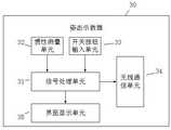
进一步的,所述姿态示教器包括信号处理单元以及与所述信号处理单元连接的惯性测量单元、开关按钮输入单元、无线通信单元和界面显示单元;所述惯性测量单元内置的惯性传感器测量出姿态示教器在东北天坐标系下的姿态数据;所述开关按钮输入单元将按钮设定的参数信息传送给信号处理单元;所述界面显示单元实时显示姿态示教器的工作状态及工作数据;参数信息和姿态数据经所述信号处理单元处理后由无线通信单元发送至计算机。Further, the attitude teaching device includes a signal processing unit, an inertial measurement unit connected to the signal processing unit, a switch button input unit, a wireless communication unit, and an interface display unit; the built-in inertial sensor of the inertial measurement unit measures The attitude data of the attitude teaching pendant under the northeast sky coordinate system; the switch button input unit transmits the parameter information set by the button to the signal processing unit; the interface display unit displays the working status and working data of the attitude teaching pendant in real time ; The parameter information and attitude data are sent to the computer by the wireless communication unit after being processed by the signal processing unit.
进一步的,所述路径规划单元和所述姿态示教单元运行在计算机上,并能加载显示被加工产品模型,建立被加工产品模型局部坐标系;Further, the path planning unit and the posture teaching unit run on a computer, and can load and display the processed product model, and establish a local coordinate system of the processed product model;
所述路径规划单元的工作过程如下:示教人员在被加工产品模型上采用计算机交互设备交互选择机器人末端执行器的一系列路径点,从而在被加工产品模型的局部坐标系中定义所述被加工产品模型的加工路径点坐标Pi(xi,yi,zi),其中i表示路径点的数目;The working process of the path planning unit is as follows: the teaching staff uses computer interactive equipment to interactively select a series of path points of the robot end effector on the processed product model, thereby defining the processed product model in the local coordinate system. Processing path point coordinates Pi (xi , yi , zi ) of the processed product model, where i represents the number of path points;
所述姿态示教单元的工作过程如下:示教编程人员操作所述姿态示教器,生成姿态数据,所述计算机按顺序读取各所述路径点的三维坐标Pi(xi,yi,zi),并按照一定的速度驱动虚拟的机器人末端执行器沿着规划的路径运动,与此同时所述姿态示教单元实时接收姿态示教器的姿态数据,规划机器人末端执行器的姿态,获得一系列的姿态Oi(ai,bi,ci)。The working process of the posture teaching unit is as follows: the teaching programmer operates the posture teaching device to generate posture data, and the computer reads the three-dimensional coordinates Pi (xi , yi ) of each path point in sequence. , zi ), and drive the virtual robot end effector to move along the planned path according to a certain speed. At the same time, the posture teaching unit receives the posture data of the posture teaching device in real time, and plans the posture of the robot end effector , to obtain a series of poses Oi (ai ,bi , c i) .
进一步的,所述增强现实注册模块的工作过程如下:Further, the working process of the augmented reality registration module is as follows:
所述相机实时采集物理机器人和物理工作环境的图像至所述计算机,所述增强现实模块根据采集的图像计算AR注册卡的坐标系OA-XAYAZA到相机坐标系OC-XCYCZC的转换矩阵

进一步的,所述虚实空间融合单元工作过程如下:Further, the working process of the virtual-real space fusion unit is as follows:
所述虚实空间融合单元通过所述计算机向所述物理机器人控制器发送机器人间歇运动控制程序,所述物理机器人控制器控制执行所述机器人间歇运动控制程序,控制所述物理机器人末端执行器实现间歇运动,间歇运动路径至少包括四个不在一条直线上的间歇运动点;在间歇运动的每个间歇运动点,所述计算机通过物理机器人控制器读取末端执行器在机器人基坐标系Ow-XwYwZw下的三维坐标Qi(Xi,Yi,Zi);同时通过相机采集物理工作环境的图像,通过计算机视觉算法识别物理机器人末端执行器,并计算末端执行器在图像中的图像坐标qi(ui,vi),根据所有特征点的图像坐标qi(ui,vi)和对应的三维坐标Qi(Xi,Yi,Zi),根据奇异值分解求最小二乘刚性转置方法求解机器人基坐标系Ow-XwYwZw到相机坐标系OC-XCYCZC的转换矩阵
转换关系如下所示:


可替代的,所述虚实空间融合单元工作过程如下:Alternatively, the working process of the virtual-real space fusion unit is as follows:
将AR注册卡放置在工作台上,拖动物理机器人,使物理机器人末端执行器的末端点依次与AR注册卡的四个顶点重合,记录重合时各顶点在机器人坐标系中Ow-XwYwZw的坐标(XW,YW,ZW)和AR注册卡坐标系OA-XAYAZA中的坐标(XA,YA,ZA);从而计算AR卡坐标系OA-XAYAZA到机器人基坐标系Ow-XwYwZw的坐标转换矩阵R,转换关系如下所示:Place the AR registration card on the workbench, drag the physical robot, and make the end points of the end effector of the physical robot coincide with the four vertices of the AR registration card in sequence. When recording the coincidence, each vertex is in the robot coordinate system Ow -Xw The coordinates (XW , YW , ZW ) of Yw Zw and the coordinates (XA , YA , ZA ) in the coordinate system OA -XA YA ZA of the AR registration card; thereby calculating the coordinates of the AR card The coordinate transformation matrix R of the system OA -XA YA ZA to the robot base coordinate system Ow -Xw Yw Zw , the conversion relationship is as follows:

进一步的,所述虚实碰撞检测模块的工作流程如下:计算机中的虚实碰撞检测模块实时从物理机器人控制器中读取物理机器人各关节的旋转角度,利用各关节的旋转角度驱动机器人三维模型的DOF关节运动,利用AR注册卡坐标系OA-XAYAZA与机器人基坐标系Ow-XwYwZ的坐标转换矩阵R,将机器人三维模型与被加工产品模型融合在同一坐标系下,使用OBB碰撞检测算法检测机器人三维模型与被加工产品模型的之间的碰撞关系。Further, the workflow of the virtual-real collision detection module is as follows: the virtual-real collision detection module in the computer reads the rotation angle of each joint of the physical robot from the physical robot controller in real time, and uses the rotation angle of each joint to drive the DOF of the three-dimensional model of the robot. Joint movement, using the coordinate transformation matrix R of the AR registration card coordinate system OA -XA YA ZA and the robot base coordinate system Ow -Xw Yw Z, the robot 3D model and the processed product model are fused in the same coordinates Under the system, the OBB collision detection algorithm is used to detect the collision relationship between the robot's 3D model and the processed product model.
技术方案二Technical solution two
一种基于增强现实技术的工业机器人示教方法,该方法是基于技术方案一所述的一种基于增强现实技术的工业机器人示教系统及方法实现的,包括系统初始化步骤和AR仿真步骤;An augmented reality technology-based industrial robot teaching method, which is implemented based on the augmented reality technology-based industrial robot teaching system and method described in Technical Solution 1, including system initialization steps and AR simulation steps;
所述系统初始化步骤如下:The system initialization steps are as follows:
S10、在计算机中建立虚拟机器人模型和被加工产品模型:在计算机中绘制与物理机器人结构尺寸相同的机器人三维模型,定义机器人三维模型各关节之间的DOF节点,然后根据物理机器人的结构和参数建立机器人正运动学模型和机器人逆运动学模型,形成虚拟机器人模型;再按照比例绘制与被实际加工产品相同的被加工产品模型;S10. Establish a virtual robot model and a processed product model in the computer: draw a three-dimensional model of the robot with the same structural size as the physical robot in the computer, define the DOF nodes between the joints of the three-dimensional robot model, and then according to the structure and parameters of the physical robot Establish the robot's forward kinematics model and robot's inverse kinematics model to form a virtual robot model; then draw the processed product model that is the same as the actual processed product in proportion;
S20、使用路径规划单元和姿态示教单元定义定义所述被加工产品模型的加工路径点坐标和机器人末端执行器的姿态;S20. Using the path planning unit and the posture teaching unit to define the processing path point coordinates of the processed product model and the posture of the robot end effector;
AR仿真阶段步骤如下:The steps of the AR simulation stage are as follows:
S30、放置一张AR注册卡,使用增强现实注册模块进行增强现实注册,实现被加工产品模型坐标系与AR注册卡坐标系OA-XAYAZA的重合;S30. Place an AR registration card, use the augmented reality registration module to perform augmented reality registration, and realize the overlap between the coordinate system of the processed product model and the coordinate system OA -XA YA ZA of the AR registration card;
S40、使用虚实空间融合单元求取被加工产品模型坐标系OA-XAYAZA到机器人基坐标系Ow-XwYwZw的转换矩阵R;S40. Use the virtual and real space fusion unit to obtain the transformation matrix R from the coordinate system OA -XA YA ZA of the model of the processed product to the base coordinate system Ow -Xw Yw Zw of the robot;
S50、使用转换矩阵R计算出被加工产品的机器人路径关键点坐标Pi(xi,yi,zi)和姿态Oi(ai,bi,ci)在机器人基坐标系Ow-XwYwZw中的坐标和方位,同时生成物理机器人控制程序;S50. Use the transformation matrix R to calculate the robot path key point coordinates Pi (xi , yi , zi ) and attitude Oi (ai , bi , ci ) of the processed product in the robot base coordinate system Ow - coordinates and orientations in Xw Yw Zw while generating the physical robot control program;
S60、物理机器人控制器执行物理机器人控制程序,计算机执行虚实碰撞检测模块,进行虚实碰撞检测;若示教位姿合理且未发生碰撞,则计算机储存该点的示教信息,否则重新设计工装夹具,或重新放置AR注册卡位置以改变工装夹具在机器人基坐标系中的位置。S60. The physical robot controller executes the physical robot control program, and the computer executes the virtual-real collision detection module to perform virtual-real collision detection; if the teaching pose is reasonable and no collision occurs, the computer stores the teaching information of this point, otherwise redesign the fixture , or reposition the AR registration card to change the position of the fixture in the robot base coordinate system.
本发明具有如下有益效果:The present invention has following beneficial effect:
本发明发明一种基于增强现实技术的工业机器人示教系统及方法,可以在增强现实环境中验证产品工装夹具结构设计是否合理,规划工装夹具在工作台上的安装方位,生成并验证工业机器人程序,将机器人作为真实的,而将工作环境(如被加工件、工装夹具等)作为虚拟的模型,采用增强现实技术验证产品及工装夹具设计,验证机器人加工程序。The invention presents an industrial robot teaching system and method based on augmented reality technology, which can verify whether the structure design of the product tooling fixture is reasonable in the augmented reality environment, plan the installation orientation of the tooling fixture on the workbench, generate and verify the industrial robot program , take the robot as real, and use the working environment (such as workpiece, fixture, etc.) as a virtual model, use augmented reality technology to verify product and fixture design, and verify robot processing procedures.
附图说明Description of drawings
图1为本发明一种基于增强现实技术的工业机器人示教系统的结构示意图;Fig. 1 is the structural representation of a kind of industrial robot teaching system based on augmented reality technology of the present invention;
图2为本发明一种基于增强现实技术的工业机器人示教系统中姿态示教器的示意图;Fig. 2 is a schematic diagram of a posture teaching device in an industrial robot teaching system based on augmented reality technology of the present invention;
图3为本发明一种基于增强现实技术的工业机器人示教方法的流程图。Fig. 3 is a flow chart of an industrial robot teaching method based on augmented reality technology according to the present invention.
图中附图标记表示为:The reference signs in the figure represent:
10、相机;20、计算机;30、姿态示教器;31、信号处理单元;32、惯性测量单元;33、开关按钮输入单元;34、无线通信单元;35、界面显示单元;40、物理机器人控制器;50、物理机器人;60、AR注册卡;61、被加工产品模型。10. Camera; 20. Computer; 30. Attitude Teaching Device; 31. Signal Processing Unit; 32. Inertial Measurement Unit; 33. Switch Button Input Unit; 34. Wireless Communication Unit; 35. Interface Display Unit; 40. Physical Robot Controller; 50. Physical robot; 60. AR registration card; 61. Processed product model.
具体实施方式Detailed ways
下面结合附图和具体实施例来对本发明进行详细的说明。The present invention will be described in detail below in conjunction with the accompanying drawings and specific embodiments.
实施例一Embodiment one
请参阅图1和图2,一种基于增强现实技术的工业机器人示教系统,包括相机10、计算机20、姿态示教器30、物理机器人单元、AR示教单元和虚拟机器人模型;Please refer to FIG. 1 and FIG. 2, an industrial robot teaching system based on augmented reality technology, including a
所述物理机器人单元包括物理机器人控制器40和物理机器人50;所述物理机器人50自设置有物理机器人基坐标系;所述物理机器人控制器40分别与所述物理机器人50和计算机20连接,所述物理机器人控制器40用于控制物理机器人50运动,并获取物理机器人50的运动轨迹;The physical robot unit includes a
所述相机10设置于物理工作环境下并与所述计算机20通信连接,用于采集物理机器人50和物理工作环境的图像至所述计算机20;The
所述姿态示教器30与所述计算机20通信连接,由示教人员握持操作,产生姿态数据并发送至所述计算机20;The
所述AR示教单元包括位于物理工作环境中的AR注册卡60和运行于计算机20中的增强现实注册模块、被加工产品模型61、路径规划单元、姿态示教单元、虚实空间融合单元和虚实碰撞检测模块;所述增强现实注册模块用于通过AR注册卡60对被加工产品模型61进行增强现实注册;所述被加工产品模型61包括被加工件三维模型和使用的工装夹具三维模型;所述路径规划单元用于规划所述被加工产品模型61的加工路径;所述姿态示教单元用于根据所述姿态数据规划物理机器人50末端执行器的姿态;所述虚实碰撞监测模块用于检测所述虚拟机器人模型是否会发生碰撞;所述虚实空间融合单元用于获取AR注册卡的坐标系与物理机器人基坐标系之间的转换矩阵;The AR teaching unit includes an
所述虚拟机器人模型运行于所述计算机20中,包括机器人三维模型、机器人正运动学模型、机器人逆运动学模型,其中机器人三维模型中包含设置于机器人关节上的DOF节点。The virtual robot model runs in the
进一步的,所述姿态示教器30包括信号处理单元31以及与所述信号处理单元31连接的惯性测量单元32、开关按钮输入单元33、无线通信单元34和界面显示单元35;所述惯性测量单元32内置的惯性传感器测量出姿态示教器30在东北天坐标系下的姿态数据;所述开关按钮输入单元33将按钮设定的参数信息传送给信号处理单元31;所述界面显示单元35实时显示姿态示教器30的工作状态及工作数据;参数信息和姿态数据经所述信号处理单元31处理后由无线通信单元34发送至计算机20。Further, the
进一步的,所述路径规划单元和所述姿态示教单元运行在计算机20上,并能加载显示被加工产品模型61,建立被加工产品模型局部坐标系;Further, the path planning unit and the posture teaching unit run on the
所述路径规划单元的工作过程如下:示教编程人员在被加工产品模型61上采用计算机交互设备(如普通鼠标、三维鼠标等)交互选择机器人末端执行器的一系列路径点,从而在被加工产品模型61的局部坐标系中定义所述被加工产品模型61的加工路径点坐标Pi(xi,yi,zi),其中i表示路径点的数目。The working process of the path planning unit is as follows: teaching programmers use computer interactive equipment (such as ordinary mouse, three-dimensional mouse, etc.) to interactively select a series of path points of the robot end effector on the processed
所述姿态示教单元的工作过程如下:示教编程人员操作所述姿态示教器30,生成姿态数据,计算机20按顺序读取所述路径点的三维坐标Pi(xi,yi,zi),并按照一定的速度驱动虚拟的机器人末端执行器沿着规划的路径运动,与此同时所述姿态示教单元实时接收姿态示教器30的姿态数据,规划机器人末端执行器的姿态,获得一系列的姿态Oi(ai,bi,ci)。The working process of the posture teaching unit is as follows: teaching programmers operate the
进一步的,所述增强现实注册模块的工作过程如下:Further, the working process of the augmented reality registration module is as follows:
所述相机10实时采集物理机器人和物理工作环境的图像至所述计算机20,所述增强现实模块根据图像计算AR注册卡60坐标系OA-XAYAZA到相机坐标系OC-XCYCZC的转换矩阵

所述虚实空间融合单元的主要目的是求取AR注册卡坐标系OA-XAYAZA与机器人基坐标系Ow-XwYwZw间的转换矩阵R。所述虚实空间融合单元工作过程如下:虚实空间融合单元向物理机器人控制器40发送机器人间歇运动控制程序,所述物理机器人控制器40控制执行所述机器人间歇运动控制程序,控制所述物理机器人50末端执行器实现间歇运动,间歇运动路径至少包括4个不在一条直线上的间歇运动点。在间歇运动的每个间歇运动点,所述计算机20通过机器人控制器40读取末端执行器在机器人基坐标系Ow-XwYwZw下的三维坐标Qi(Xi,Yi,Zi);同时通过相机10读取物理工作环境的图像,通过一定的计算机视觉算法识别末端执行器,并计算末端执行器在图像中的图像坐标qi(ui,vi),根据所有特征点的图像坐标qi(ui,vi)和对应的三维坐标Qi(Xi,Yi,Zi),根据奇异值分解求最小二乘刚性转置方法求解机器人基坐标系Ow-XwYwZw到相机坐标系OC-XCYCZC的转换矩阵


可选的,建立AR注册卡坐标系与机器人基坐标系中的转换矩阵R的方法如下:Optionally, the method of establishing the transformation matrix R in the coordinate system of the AR registration card and the base coordinate system of the robot is as follows:
在工作台上放置一个AR注册卡60,拖动物理机器人50,使物理机器人末端执行器的末端点依次与AR注册卡的4个顶点重合,记录重合时各顶点在机器人坐标系中Ow-XwYwZw的坐标(XW,YW,ZW)和AR注册卡坐标系OA-XAYAZA中的坐标(XA,YA,ZA);从而计算AR卡坐标系OA-XAYAZA到机器人基坐标系Ow-XwYwZw的坐标转换矩阵R,转换关系如下所示:Place an

利用转换矩阵R,计算出示教路径点Pi(xi,yi,zi)和姿态Oi(ai,bi,ci)在机器人基坐标系Ow-XwYwZw中的坐标和方位,即可生成机器人的加工轨迹。Using the transformation matrix R, calculate the teaching path point Pi (xi , yi , zi ) and attitude Oi (ai ,bi , c i) in the robot base coordinate system Ow -Xw Yw Zw The coordinates and orientation in the robot can generate the machining trajectory of the robot.
所述虚实碰撞检测模块的工作流程如下:将加工程序发送给物理机器人,物理机器人产生运动,在虚实环境中进行碰撞检测。所述的虚实碰撞检测方法为:计算机中的虚实碰撞检测模块66实时从机器人控制器中读取物理机器人各关节的旋转角度,利用各关节的旋转角度驱动虚拟机器人模型的关节DOF运动,利用AR注册卡坐标系OA-XAYAZA与机器人基坐标系Ow-XwYwZ的坐标转换矩阵R,将虚拟机器人模型与被加工产品模型63融合在同一坐标系下,使用OBB碰撞检测算法检测虚拟机器人三维模型与被加工产品模型61的之间的碰撞。The workflow of the virtual-real collision detection module is as follows: the processing program is sent to the physical robot, and the physical robot generates motion to perform collision detection in the virtual-real environment. The virtual-real collision detection method is as follows: the virtual-real collision detection module 66 in the computer reads the rotation angles of each joint of the physical robot from the robot controller in real time, uses the rotation angles of each joint to drive the joint DOF movement of the virtual robot model, and uses the AR The coordinate transformation matrix R of the registration card coordinate system OA -XA YA ZA and the robot base coordinate system Ow -Xw Yw Z is used to fuse the virtual robot model and the processed product model 63 in the same coordinate system, using The OBB collision detection algorithm detects the collision between the three-dimensional model of the virtual robot and the
实施例二Embodiment two
参见图3,一种基于增强现实技术的工业机器人示教方法,该方法是基于实施例一所述的一种基于增强现实技术的工业机器人示教系统及方法实现的,包括系统初始化步骤和AR仿真步骤;Referring to FIG. 3 , a teaching method for an industrial robot based on augmented reality technology is implemented based on the system and method for teaching an industrial robot based on augmented reality technology described in Embodiment 1, including system initialization steps and AR Simulation steps;
所述系统初始化步骤如下:The system initialization steps are as follows:
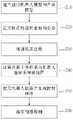
S10、在计算机20中建立虚拟机器人模型和被加工产品模型61:在计算机中绘制与物理机器人50结构尺寸相同的机器人三维模型,定义机器人三维模型各关节之间的DOF节点,然后根据物理机器人50的结构和参数建立机器人正运动学模型和机器人逆运动学模型,形成虚拟机器人模型;再按照比例绘制与被实际加工产品相同的被加工产品模型61;S10. Establish a virtual robot model and a processed
S20、使用路径规划单元和姿态示教单元定义定义所述被加工产品模型61的加工路径点坐标和机器人末端执行器的姿态;S20. Using the path planning unit and the posture teaching unit to define the coordinates of the processing path point of the processed
AR仿真阶段步骤如下:The steps of the AR simulation stage are as follows:
S30、放置一张AR注册卡60,使用增强现实注册模块进行增强现实注册,实现被加工产品模型坐标系与AR注册卡坐标系OA-XAYAZA的重合;S30, place an
S40、使用虚实空间融合单元求取被加工产品模型坐标系OA-XAYAZA到机器人基坐标系Ow-XwYwZw的转换矩阵R;S40. Use the virtual and real space fusion unit to obtain the transformation matrix R from the coordinate system OA -XA YA ZA of the model of the processed product to the base coordinate system Ow -Xw Yw Zw of the robot;
S50、使用转换矩阵R计算出被加工产品61的机器人路径关键点坐标Pi(xi,yi,zi)和姿态Oi(ai,bi,ci)在机器人基坐标系Ow-XwYwZw中的坐标和方位,同时生成物理机器人控制程序;S50. Use the transformation matrix R to calculate the robot path key point coordinates Pi (xi , yi , zi ) and posture Oi (ai , bi , ci ) of the processed
S60、物理机器人控制器40执行物理机器人控制程序,计算机20执行虚实碰撞检测模块,进行虚实碰撞检测;若示教位姿合理且未发生碰撞,则计算机20储存该点的示教信息,否则重新设计工装夹具,或重新放置AR注册卡60位置以改变工装夹具在机器人基坐标系中的位置。S60, the
以上所述仅为本发明的实施例,并非因此限制本发明的专利范围,凡是利用本发明说明书及附图内容所作的等效结构或等效流程变换,或直接或间接运用在其他相关的技术领域,均同理包括在本发明的专利保护范围内。The above is only an embodiment of the present invention, and does not limit the patent scope of the present invention. Any equivalent structure or equivalent process transformation made by using the description of the present invention and the contents of the accompanying drawings, or directly or indirectly used in other related technologies fields, all of which are equally included in the scope of patent protection of the present invention.
Claims (7)
Translated fromChinese


Priority Applications (1)
| Application Number | Priority Date | Filing Date | Title |
|---|---|---|---|
| CN202010211069.4ACN111267073B (en) | 2020-03-24 | 2020-03-24 | Industrial robot teaching system and method based on augmented reality technology |
Applications Claiming Priority (1)
| Application Number | Priority Date | Filing Date | Title |
|---|---|---|---|
| CN202010211069.4ACN111267073B (en) | 2020-03-24 | 2020-03-24 | Industrial robot teaching system and method based on augmented reality technology |
Publications (2)
| Publication Number | Publication Date |
|---|---|
| CN111267073A CN111267073A (en) | 2020-06-12 |
| CN111267073Btrue CN111267073B (en) | 2022-11-15 |
Family
ID=70993005
Family Applications (1)
| Application Number | Title | Priority Date | Filing Date |
|---|---|---|---|
| CN202010211069.4AActiveCN111267073B (en) | 2020-03-24 | 2020-03-24 | Industrial robot teaching system and method based on augmented reality technology |
Country Status (1)
| Country | Link |
|---|---|
| CN (1) | CN111267073B (en) |
Families Citing this family (9)
| Publication number | Priority date | Publication date | Assignee | Title |
|---|---|---|---|---|
| CN111843997A (en)* | 2020-07-29 | 2020-10-30 | 上海大学 | Handheld general teaching system for mechanical arm and operation method thereof |
| WO2022036634A1 (en)* | 2020-08-20 | 2022-02-24 | 青岛理工大学 | Assembly/disassembly operation-oriented augmented reality guidance and remote collaboration development system |
| CN112454333B (en)* | 2020-11-26 | 2022-02-11 | 青岛理工大学 | Robot teaching system and method based on image segmentation and surface electromyogram signals |
| CN112650436A (en)* | 2020-12-11 | 2021-04-13 | 深圳市越疆科技有限公司 | Robot operation method and device based on augmented reality and storage medium |
| CN112847301B (en)* | 2020-12-21 | 2023-05-19 | 山东华数智能科技有限公司 | Robot augmented reality teaching programming method based on portable terminal |
| CN112801977B (en)* | 2021-01-28 | 2022-11-22 | 青岛理工大学 | A Method for Estimating and Monitoring the Relative Pose of Assembly Parts Based on Deep Learning |
| CN112686227B (en)* | 2021-03-12 | 2021-07-06 | 泰瑞数创科技(北京)有限公司 | Product quality inspection method and device based on augmented reality and man-machine comprehensive detection |
| CN114193438B (en)* | 2021-12-15 | 2023-12-08 | 北京航星机器制造有限公司 | Method and device for controlling robot based on touch screen |
| CN114407015B (en)* | 2022-01-28 | 2024-11-05 | 青岛理工大学 | A teleoperated robot online teaching system and method based on digital twin |
Citations (8)
| Publication number | Priority date | Publication date | Assignee | Title |
|---|---|---|---|---|
| CN101739478A (en)* | 2008-11-17 | 2010-06-16 | 北京卫星环境工程研究所 | Spacecraft assembly simulation technique-based virtual assembly system and virtual assembly method |
| CN101791801A (en)* | 2010-01-15 | 2010-08-04 | 广东工业大学 | Industrial robot motion planning and performance testing system and implementation method thereof |
| CN106182018A (en)* | 2016-07-30 | 2016-12-07 | 福州大学 | A kind of grinding and polishing industrial robot off-line programing method based on workpiece three-dimensional graph |
| CN107309882A (en)* | 2017-08-14 | 2017-11-03 | 青岛理工大学 | Robot teaching programming system and method |
| CN107351058A (en)* | 2017-06-08 | 2017-11-17 | 华南理工大学 | Robot teaching method based on augmented reality |
| CN108398922A (en)* | 2018-01-24 | 2018-08-14 | 华南理工大学 | A kind of robot abrasive band polishing Virtual Demonstration method based on force feedback |
| CN109773785A (en)* | 2018-12-29 | 2019-05-21 | 南京埃斯顿机器人工程有限公司 | A kind of industrial robot collision-proof method |
| CN110238831A (en)* | 2019-07-23 | 2019-09-17 | 青岛理工大学 | Robot teaching system and method based on RGB-D image and teaching device |
Family Cites Families (3)
| Publication number | Priority date | Publication date | Assignee | Title |
|---|---|---|---|---|
| US7890194B2 (en)* | 2005-12-13 | 2011-02-15 | Brooks Automation, Inc. | Robotics programming interface |
| US9855664B2 (en)* | 2015-11-25 | 2018-01-02 | Denso Wave Incorporated | Robot safety system |
| JP6763846B2 (en)* | 2017-11-24 | 2020-09-30 | ファナック株式会社 | Teaching device and teaching method for teaching robots |
- 2020
- 2020-03-24CNCN202010211069.4Apatent/CN111267073B/enactiveActive
Patent Citations (8)
| Publication number | Priority date | Publication date | Assignee | Title |
|---|---|---|---|---|
| CN101739478A (en)* | 2008-11-17 | 2010-06-16 | 北京卫星环境工程研究所 | Spacecraft assembly simulation technique-based virtual assembly system and virtual assembly method |
| CN101791801A (en)* | 2010-01-15 | 2010-08-04 | 广东工业大学 | Industrial robot motion planning and performance testing system and implementation method thereof |
| CN106182018A (en)* | 2016-07-30 | 2016-12-07 | 福州大学 | A kind of grinding and polishing industrial robot off-line programing method based on workpiece three-dimensional graph |
| CN107351058A (en)* | 2017-06-08 | 2017-11-17 | 华南理工大学 | Robot teaching method based on augmented reality |
| CN107309882A (en)* | 2017-08-14 | 2017-11-03 | 青岛理工大学 | Robot teaching programming system and method |
| CN108398922A (en)* | 2018-01-24 | 2018-08-14 | 华南理工大学 | A kind of robot abrasive band polishing Virtual Demonstration method based on force feedback |
| CN109773785A (en)* | 2018-12-29 | 2019-05-21 | 南京埃斯顿机器人工程有限公司 | A kind of industrial robot collision-proof method |
| CN110238831A (en)* | 2019-07-23 | 2019-09-17 | 青岛理工大学 | Robot teaching system and method based on RGB-D image and teaching device |
Non-Patent Citations (4)
| Title |
|---|
| 6自由度工业机器人增强现实示教研究;张石磊;《6自由度工业机器人增强现实示教研究》;中国优秀硕士学位论文全文数据库;20190515(第5(2019)期);I138-1666* |
| A Projection-based User Interface for Industrial Robots;Gunther Reinhart;《A Projection-based User Interface for Industrial Robots》;IEEE;20071029;第67-71页* |
| 基于增强现实及自然人机交互的机器人示教再现技术研究;陈偕权;《基于增强现实及自然人机交互的机器人示教再现技术研究》;中国优秀硕士学位论文全文数据库;20190115(第1(2019)期);I140-1922* |
| 基于增强现实的6自由度工业机器人示教研究;张石磊;《基于增强现实的6自由度工业机器人示教研究》;机电工程;20190120;第36卷(第1期);第77-83页* |
Also Published As
| Publication number | Publication date |
|---|---|
| CN111267073A (en) | 2020-06-12 |
Similar Documents
| Publication | Publication Date | Title |
|---|---|---|
| CN111267073B (en) | Industrial robot teaching system and method based on augmented reality technology | |
| CN110238831B (en) | Robot teaching system and method based on RGB-D image and teaching device | |
| Pan et al. | Augmented reality-based robot teleoperation system using RGB-D imaging and attitude teaching device | |
| CN108161904B (en) | Robot online teaching device, system, method and equipment based on augmented reality | |
| CN110385694B (en) | Robot motion teaching device, robot system, and robot control device | |
| Yew et al. | Immersive augmented reality environment for the teleoperation of maintenance robots | |
| Asfour et al. | Toward humanoid manipulation in human-centred environments | |
| US20180117766A1 (en) | Device, method, program and recording medium, for simulation of article arraying operation performed by robot | |
| CN106514667B (en) | Human-robot collaboration system based on Kinect bone tracking and calibration-free visual servoing | |
| CN108638069A (en) | A kind of mechanical arm tail end precise motion control method | |
| CN108422435A (en) | Remote monitoring and control system based on augmented reality | |
| CN206326605U (en) | A kind of intelligent teaching system based on machine vision | |
| CN113829343B (en) | Real-time multitasking and multi-man-machine interaction system based on environment perception | |
| CN110815189A (en) | Robot rapid teaching system and method based on mixed reality | |
| JPS62232006A (en) | robot system | |
| CN108673505A (en) | A kind of mechanical arm tail end precise motion control method | |
| CN104708517A (en) | Industrial robot automatic grinding and polishing system based on ROS | |
| CN104842356B (en) | A multi-palletizing robot teaching method based on distributed computing and machine vision | |
| CN110480657A (en) | A kind of labyrinth environment space robot world remote control system | |
| CN112109074A (en) | Robot target image capturing method | |
| CN110142770A (en) | A robot teaching system and method based on a head-mounted display device | |
| CN117984322A (en) | Force sense guiding teleoperation system based on double-arm cooperation potential field and control method | |
| CN107214679A (en) | Mechanical arm man-machine interactive system based on body-sensing sensor | |
| CN110142769A (en) | ROS platform online robotic arm teaching system based on human gesture recognition | |
| Abdi et al. | A hybrid AI-based adaptive path planning for intelligent robot arms |
Legal Events
| Date | Code | Title | Description |
|---|---|---|---|
| PB01 | Publication | ||
| PB01 | Publication | ||
| SE01 | Entry into force of request for substantive examination | ||
| SE01 | Entry into force of request for substantive examination | ||
| GR01 | Patent grant | ||
| GR01 | Patent grant |