CN111265183B - Retina blood flow measuring device based on light beam parallel scanning mode - Google Patents
Retina blood flow measuring device based on light beam parallel scanning modeDownload PDFInfo
- Publication number
- CN111265183B CN111265183BCN202010100741.2ACN202010100741ACN111265183BCN 111265183 BCN111265183 BCN 111265183BCN 202010100741 ACN202010100741 ACN 202010100741ACN 111265183 BCN111265183 BCN 111265183B
- Authority
- CN
- China
- Prior art keywords
- blood flow
- light
- scanning
- human eye
- retina
- Prior art date
- Legal status (The legal status is an assumption and is not a legal conclusion. Google has not performed a legal analysis and makes no representation as to the accuracy of the status listed.)
- Active
Links
- 230000017531blood circulationEffects0.000titleclaimsabstractdescription48
- 210000001525retinaAnatomy0.000titleclaimsabstractdescription37
- 230000003287optical effectEffects0.000claimsabstractdescription63
- 210000004204blood vesselAnatomy0.000claimsabstractdescription44
- 230000002207retinal effectEffects0.000claimsabstractdescription36
- 238000005259measurementMethods0.000claimsabstractdescription30
- 238000001514detection methodMethods0.000claimsabstractdescription24
- 210000001210retinal vesselAnatomy0.000claimsabstractdescription11
- 210000001508eyeAnatomy0.000claimsdescription49
- 239000000523sampleSubstances0.000claimsdescription18
- 239000013307optical fiberSubstances0.000claimsdescription14
- 239000000835fiberSubstances0.000claimsdescription13
- 238000000034methodMethods0.000claimsdescription9
- 210000005252bulbus oculiAnatomy0.000claimsdescription8
- 239000008280bloodSubstances0.000claimsdescription6
- 210000004369bloodAnatomy0.000claimsdescription6
- 230000010287polarizationEffects0.000claimsdescription5
- 230000003595spectral effectEffects0.000claimsdescription4
- 239000004973liquid crystal related substanceSubstances0.000claimsdescription3
- 238000001228spectrumMethods0.000claimsdescription3
- 238000005516engineering processMethods0.000abstractdescription5
- 238000003745diagnosisMethods0.000abstractdescription2
- 201000010099diseaseDiseases0.000abstractdescription2
- 208000037265diseases, disorders, signs and symptomsDiseases0.000abstractdescription2
- 239000003814drugSubstances0.000abstractdescription2
- 230000001737promoting effectEffects0.000abstractdescription2
- 238000011160researchMethods0.000abstractdescription2
- 238000012014optical coherence tomographyMethods0.000description17
- 238000010586diagramMethods0.000description14
- 206010025421MaculeDiseases0.000description4
- 210000001747pupilAnatomy0.000description3
- 230000005540biological transmissionEffects0.000description2
- 238000004364calculation methodMethods0.000description2
- 238000012545processingMethods0.000description2
- 238000002310reflectometryMethods0.000description2
- 230000000007visual effectEffects0.000description2
- 238000004458analytical methodMethods0.000description1
- 230000009286beneficial effectEffects0.000description1
- 239000012472biological sampleSubstances0.000description1
- 238000003384imaging methodMethods0.000description1
- 238000012986modificationMethods0.000description1
- 230000004048modificationEffects0.000description1
- 238000012634optical imagingMethods0.000description1
- 238000004088simulationMethods0.000description1
- 238000012360testing methodMethods0.000description1
- 238000000844transformationMethods0.000description1
- 230000009466transformationEffects0.000description1
- 238000013519translationMethods0.000description1
- 238000002834transmittanceMethods0.000description1
Images


Classifications
- A—HUMAN NECESSITIES
- A61—MEDICAL OR VETERINARY SCIENCE; HYGIENE
- A61B—DIAGNOSIS; SURGERY; IDENTIFICATION
- A61B3/00—Apparatus for testing the eyes; Instruments for examining the eyes
- A61B3/10—Objective types, i.e. instruments for examining the eyes independent of the patients' perceptions or reactions
- A61B3/102—Objective types, i.e. instruments for examining the eyes independent of the patients' perceptions or reactions for optical coherence tomography [OCT]
- A—HUMAN NECESSITIES
- A61—MEDICAL OR VETERINARY SCIENCE; HYGIENE
- A61B—DIAGNOSIS; SURGERY; IDENTIFICATION
- A61B3/00—Apparatus for testing the eyes; Instruments for examining the eyes
- A61B3/10—Objective types, i.e. instruments for examining the eyes independent of the patients' perceptions or reactions
- A61B3/12—Objective types, i.e. instruments for examining the eyes independent of the patients' perceptions or reactions for looking at the eye fundus, e.g. ophthalmoscopes
- A61B3/1225—Objective types, i.e. instruments for examining the eyes independent of the patients' perceptions or reactions for looking at the eye fundus, e.g. ophthalmoscopes using coherent radiation
- A61B3/1233—Objective types, i.e. instruments for examining the eyes independent of the patients' perceptions or reactions for looking at the eye fundus, e.g. ophthalmoscopes using coherent radiation for measuring blood flow, e.g. at the retina
- A—HUMAN NECESSITIES
- A61—MEDICAL OR VETERINARY SCIENCE; HYGIENE
- A61B—DIAGNOSIS; SURGERY; IDENTIFICATION
- A61B3/00—Apparatus for testing the eyes; Instruments for examining the eyes
- A61B3/10—Objective types, i.e. instruments for examining the eyes independent of the patients' perceptions or reactions
- A61B3/12—Objective types, i.e. instruments for examining the eyes independent of the patients' perceptions or reactions for looking at the eye fundus, e.g. ophthalmoscopes
- A61B3/1241—Objective types, i.e. instruments for examining the eyes independent of the patients' perceptions or reactions for looking at the eye fundus, e.g. ophthalmoscopes specially adapted for observation of ocular blood flow, e.g. by fluorescein angiography
Landscapes
- Health & Medical Sciences (AREA)
- Life Sciences & Earth Sciences (AREA)
- Molecular Biology (AREA)
- Surgery (AREA)
- Biophysics (AREA)
- Ophthalmology & Optometry (AREA)
- Engineering & Computer Science (AREA)
- Biomedical Technology (AREA)
- Heart & Thoracic Surgery (AREA)
- Medical Informatics (AREA)
- Veterinary Medicine (AREA)
- Physics & Mathematics (AREA)
- Animal Behavior & Ethology (AREA)
- General Health & Medical Sciences (AREA)
- Public Health (AREA)
- Hematology (AREA)
- Nuclear Medicine, Radiotherapy & Molecular Imaging (AREA)
- Radiology & Medical Imaging (AREA)
- Vascular Medicine (AREA)
- Eye Examination Apparatus (AREA)
- Measuring Pulse, Heart Rate, Blood Pressure Or Blood Flow (AREA)
Abstract
Translated fromChinese
Description
Translated fromChinese技术领域technical field
本发明涉及医用光学检测领域,特别涉及一种基于光束平行扫描模式的视网膜血流测量装置,是一种眼科光学检测装置,具有对人眼视网膜的血液流量进行检测的功能。The invention relates to the field of medical optical detection, in particular to a retinal blood flow measurement device based on a beam parallel scanning mode, which is an ophthalmic optical detection device with the function of detecting the blood flow of the retina of the human eye.
背景技术Background technique
光学相干层析成像技术(OCT)是一种非接触、无损伤的医用光学成像技术。通过对样品内部散射光的检测,OCT可以对生物样品的结构进行高分辨的成像,分辨率在微米量级。除了提供组织形态学的信息,OCT也可以探测出来自生物组织散射光的多普勒频率移动,从而对组织内部的血液流动进行分析测量。Optical coherence tomography (OCT) is a non-contact, non-invasive medical optical imaging technology. By detecting the scattered light inside the sample, OCT can perform high-resolution imaging of the structure of biological samples with a resolution on the order of microns. In addition to providing information on tissue morphology, OCT can also detect Doppler frequency shifts in scattered light from biological tissue, allowing analytical measurements of blood flow within the tissue.
在多普勒OCT中,流动的血液会对散射光产生一个多普勒频率移动(Δf),In Doppler OCT, flowing blood produces a Doppler frequency shift (Δf) on scattered light,
Δf=-(2nVcosα)/λ0 (1)Δf=-(2nVcosα)/λ0 (1)
其中n为组织的折射率、V为血液的流动速度、λ0为探测光的中心波长、α为探测光和血液流动方向之间的夹角,被称为多普勒角。通过分析OCT的干涉信号,来自组织的多普勒频率移动Δf可以被检测出来。但是,为了获得血液的真实流速V,单有频率移动Δf是不够的,人们还需要知道探测光束和血液流动方向之间的夹角α。Where n is the refractive index of the tissue, V is the flow velocity of the blood, λ0 is the central wavelength of the probe light, and α is the angle between the probe light and the blood flow direction, which is called the Doppler angle. By analyzing the interference signal of the OCT, the Doppler frequency shift Δf from the tissue can be detected. However, in order to obtain the true flow velocity V of the blood, it is not enough to move the frequency Δf alone, one also needs to know the angle α between the probe beam and the blood flow direction.
当探测光倾斜扫描血管时,通过分析血管在组织三维结构中的空间走向,研究人员可以计算出多普勒角α,并利用这一技术在人眼的视盘区成功测量了进入(或流出)人眼视网膜血液的总流量。但这种方法在测量人眼视场中心区(黄斑附近)的血管分支时遇到了困难。人眼的视网膜是一个半径为R的球面,在视场中心区,视网膜的血管分布在半径为R的球面上。在眼科OCT中,传统的扫描方式是使探测光通过瞳孔中心进行扫描,探测光束和视网膜表面血管之间的夹角接近90度,因此,在采集到的人眼视网膜结构图中,血管的倾斜度太小,利用分析血管空间走向测得的多普勒角度误差太大,不够准确。When the probe light scans the blood vessels obliquely, by analyzing the spatial orientation of the blood vessels in the three-dimensional structure of the tissue, the researchers can calculate the Doppler angle α and use this technique to successfully measure the entry (or outflow) in the optic disc of the human eye. The total flow of retinal blood in the human eye. But this method has encountered difficulties in measuring blood vessel branches in the center of the human eye's visual field (near the macula). The retina of the human eye is a spherical surface with a radius of R. In the central area of the field of view, the blood vessels of the retina are distributed on the spherical surface with a radius of R. In ophthalmic OCT, the traditional scanning method is to scan the probe light through the center of the pupil, and the angle between the probe beam and the blood vessels on the retinal surface is close to 90 degrees. If the degree is too small, the error of the Doppler angle measured by analyzing the spatial direction of the blood vessel is too large and not accurate enough.
为了测量人眼视场中心区的血液流量,研究人员开发了双光路OCT系统,利用两束光会聚扫描视网膜表面,这种技术不直接测量多普勒角度α,而是通过设定两束探测光之间的夹角来计算血液的真实流速。这种技术由于采用的是两套OCT系统,成本较高,调整复杂,不利于临床应用,很难获得推广。另外,这种技术在理论上不够完备,在光束的入射方向上要求探测光和待测血管接近垂直,并需要检测扫描方向和血管之间的夹角作为辅助参数。In order to measure the blood flow in the central area of the human visual field, the researchers developed a dual-optical OCT system, which uses two beams of light to converge to scan the retinal surface. This technology does not directly measure the Doppler angle α, but by setting two beams to detect The angle between the lights is used to calculate the true flow rate of the blood. Since this technology uses two sets of OCT systems, the cost is high and the adjustment is complicated, which is not conducive to clinical application and is difficult to be popularized. In addition, this technique is not theoretically complete, and requires that the detection light and the blood vessel to be measured are close to vertical in the incident direction of the beam, and the angle between the scanning direction and the blood vessel needs to be detected as an auxiliary parameter.
发明内容SUMMARY OF THE INVENTION
发明目的:针对现有技术中存在的问题,本发明提供一种基于光束平行扫描模式的视网膜血流测量装置,可以有效增加探测光束和视网膜血管之间的夹角,从而实现对人眼视网膜不同部位血管分支血液流量的定量检测,并增加测量结果的可靠性。Purpose of the invention: In view of the problems existing in the prior art, the present invention provides a retinal blood flow measurement device based on a beam parallel scanning mode, which can effectively increase the angle between the detection beam and the retinal blood vessels, so as to achieve different retinal measurements of the human eye. Quantitative detection of blood flow in site vessel branches and increased reliability of measurement results.
技术方案:本发明提供了一种基于光束平行扫描模式的视网膜血流测量装置,光源发出的光与光纤耦合器的入射端口连接,所述光源的光经过所述光纤耦合器分别进入参考光路单元和光束扫描单元,由所述光束扫描单元返回的样品光信号通过所述光纤耦合器进入光谱仪单元接收光信号;数据采集控制单元分别与所述光束扫描单元和所述光谱仪单元电连接;所述参考光路单元中,第一参考臂的光学长度大于第二参考臂的光学长度;探测光束通过人眼前焦点进入人眼;在眼睛内部,探测光束以近似平行于光轴的方式对人眼的视网膜进行扫描;为了实现对视网膜不同部位血管的倾斜角度入射,使用一个带有十字叉的定位靶来调节眼球的转动,将定位靶上的十字叉在平面内移动,通过转动眼球观察十字叉,在不改变光束扫描方向的情况下,对视网膜不同区间中的血管进行扫描测量;探测光束对待测视网膜血管进行两次扫描,两个扫描面之间有一定的空间间隔;设第一次扫描获得的血管中心位置为C1,第二次扫描获得的血管中心位置为C2,则根据血管中心C1和C2的位置坐标,计算出血管的方向矢量r,而OCT 扫描光束的方向矢量为z,则扫描光束和血管之间夹角α满足 cosα=(r·z)/S;其中S为C1和C2之间的距离;将上式的结果代入公式Δf=-(2nVcosα)/λ0中,计算出待测血管中的血流速度,其中,Δf为多普勒频率移动,n为组织的折射率、V为血液的流动速度、λ0为探测光的中心波长、α为探测光和血液流动方向之间的夹角——多普勒角。Technical solution: The present invention provides a retinal blood flow measurement device based on a beam parallel scanning mode. The light emitted by the light source is connected to the incident port of the optical fiber coupler, and the light of the light source enters the reference optical path unit respectively through the optical fiber coupler. and a beam scanning unit, the sample optical signal returned by the beam scanning unit enters the spectrometer unit through the fiber coupler to receive the optical signal; the data acquisition control unit is respectively electrically connected with the beam scanning unit and the spectrometer unit; the In the reference optical path unit, the optical length of the first reference arm is greater than the optical length of the second reference arm; the detection beam enters the human eye through the focus of the human eye; inside the eye, the detection beam is approximately parallel to the optical axis to the retina of the human eye. Scanning; in order to achieve oblique angle incidence of blood vessels in different parts of the retina, a positioning target with a cross is used to adjust the rotation of the eyeball, the cross on the positioning target is moved in the plane, and the cross is observed by rotating the eyeball. Under the condition of not changing the scanning direction of the beam, the blood vessels in different regions of the retina are scanned and measured; the detection beam scans the retinal blood vessels to be measured twice, and there is a certain spatial interval between the two scanning planes; The position of the blood vessel center is C1 , and the position of the blood vessel center obtained by the second scan is C2 , then according to the position coordinates of the blood vessel centers C1 and C2 , the direction vector r of the blood vessel is calculated, and the direction vector of the OCT scanning beam is z , then the angle α between the scanning beam and the blood vessel satisfies cosα=(r z)/S; where S is the distance between C1 and C2 ; substitute the result of the above formula into the formula Δf=-(2nVcosα)/λ0 , calculate the blood flow velocity in the blood vessel to be measured, where Δf is the Doppler frequency shift, n is the refractive index of the tissue, V is the blood flow velocity, λ0 is the central wavelength of the detection light, α is the detection The angle between light and the direction of blood flow - the Doppler angle.
进一步地,所述光源发出的光通过光学隔离器与所述光纤耦合器的入射端口连接。Further, the light emitted by the light source is connected to the incident port of the optical fiber coupler through an optical isolator.
优选地,所述光束扫描单元包括与所述光纤耦合器连接的第一准直透镜,与所述第一准直透镜连接的第一反射镜、与所述第一反射镜连接的二维扫描振镜,以及与所述二维扫描振镜连接的第一透镜、第二反射镜和第二透镜;从所述光纤耦合器输出的光经过所述第一准直透镜和所述第一反射镜入射到所述二维扫描振镜上,由所述二维扫描振镜反射的光束经过所述第一透镜、所述第二反射镜和所述第二透镜进入人眼,对视网膜进行扫描。Preferably, the beam scanning unit includes a first collimating lens connected with the fiber coupler, a first reflecting mirror connected with the first collimating lens, and a two-dimensional scanning lens connected with the first reflecting mirror a galvanometer, and a first lens, a second reflector and a second lens connected to the two-dimensional scanning galvanometer; the light output from the fiber coupler passes through the first collimating lens and the first reflection The mirror is incident on the two-dimensional scanning galvanometer, and the light beam reflected by the two-dimensional scanning galvanometer enters the human eye through the first lens, the second reflecting mirror and the second lens, and scans the retina .
优选地,所述光束扫描单元还包含液晶显示器定位靶,所述定位靶上的十字叉图像通过第三透镜和所述第二透镜进入人眼,投影在视网膜上。Preferably, the beam scanning unit further comprises a positioning target of a liquid crystal display, and the image of the cross on the positioning target enters the human eye through the third lens and the second lens, and is projected on the retina.
优选地,所述数据采集控制单元包括计算机,以及与所述计算机电连接的图像采集卡和扫描驱动卡,所述图像采集卡与所述光谱仪单元中的信号接收装置电连接,所述扫描驱动卡与所述二维扫描振镜的角度偏转装置电连接;所述图像采集卡采集所述光谱仪单元中的信号接收装置接收的干涉光谱信号后传输至所述计算机处理,并发出驱动控制信号传输给所述扫描驱动卡,所述扫描驱动卡控制所述二维扫描振镜的角度偏转。Preferably, the data acquisition control unit includes a computer, an image acquisition card and a scan driver card electrically connected to the computer, the image acquisition card is electrically connected to the signal receiving device in the spectrometer unit, and the scan driver The card is electrically connected to the angle deflection device of the two-dimensional scanning galvanometer; the image acquisition card collects the interference spectrum signal received by the signal receiving device in the spectrometer unit and transmits it to the computer for processing, and sends a drive control signal for transmission To the scan driver card, the scan driver card controls the angular deflection of the two-dimensional scanning galvanometer.
优选地,所述第一参考臂包括第二准直透镜、光强衰减器、第一光路开关和第一全反射镜;所述第二参考臂包括所述第二准直透镜、所述光强衰减器、半透半反镜、第二光路开关和第二全反射镜。Preferably, the first reference arm includes a second collimating lens, a light intensity attenuator, a first optical path switch and a first total reflection mirror; the second reference arm includes the second collimating lens, the light Strong attenuator, half mirror, second optical path switch and second total reflection mirror.
优选地,所述第一全反射镜安装在第一一维移动台上,所述第一一维移动台沿着入射光方向前后移动以调整所述第一参考臂的光程;所述第二全反射镜安装在第二一维移动台上,所述第二一维移动台沿着入射光方向前后移动以调整所述第二参考臂的光程。Preferably, the first total reflection mirror is mounted on a first one-dimensional moving stage, and the first one-dimensional moving stage moves back and forth along the incident light direction to adjust the optical path of the first reference arm; the first one-dimensional moving stage moves forward and backward along the incident light direction; Two total reflection mirrors are mounted on the second one-dimensional moving stage, and the second one-dimensional moving stage moves back and forth along the incident light direction to adjust the optical path of the second reference arm.
优选地,所述第一参考臂的光学长度比所述第二参考臂的光学长度长17毫米。Preferably, the optical length of the first reference arm is 17 mm longer than the optical length of the second reference arm.
进一步地,所述参考光路单元与所述光纤耦合器连接的光纤上,还安装有偏振控制器。Further, a polarization controller is also installed on the optical fiber connecting the reference optical path unit and the optical fiber coupler.
优选地,所述光谱仪单元包括第三准直透镜、光栅、聚焦透镜和线阵CCD,经过所述光纤耦合器干涉的光进入所述光谱仪单元后,由所述第三准直透镜准直,然后依次经过所述光栅的衍射和所述聚焦透镜的汇聚,传输至所述线阵CCD的表面,所述线阵CCD接收的干涉光谱信号经图像采集卡传输至所述数据采集控制单元。Preferably, the spectrometer unit includes a third collimating lens, a grating, a focusing lens and a linear CCD. After the light interfered by the fiber coupler enters the spectrometer unit, it is collimated by the third collimating lens, Then, through the diffraction of the grating and the convergence of the focusing lens in sequence, it is transmitted to the surface of the linear array CCD, and the interference spectrum signal received by the linear array CCD is transmitted to the data acquisition control unit through the image acquisition card.
有益效果:本装置可对人眼视网膜不同部位的血管分支以及视网膜总的血液流量进行定量检测。该装置使探测光束通过人眼的前焦点,然后以平行于人眼主光轴或辐轴的方式对人眼视网膜进行扫描;光束平行入射模式可以有效增大探测光束和视网膜血管之间的夹角,从而实现对人眼视网膜不同部位血管分支血液流量的定量检测,提高血流测量结果的准确性。探测光束对待测血管的两个不同位置进行扫描,利用获得的两幅多普勒OCT图像来计算探测光和待测血管之间的多普勒角度,以实现对血液流速和流量的定量测量。同时,使用单光束OCT系统对人眼视网膜的血流进行测量,减小了OCT视网膜血流测量装置的复杂性,并大大降低了成本,有利于促进视网膜血流测量技术在医学临床上的普及应用,为眼科疾病的诊断和研究提供帮助。Beneficial effects: The device can quantitatively detect the blood vessel branches in different parts of the retina of the human eye and the total blood flow of the retina. The device makes the detection beam pass through the front focus of the human eye, and then scans the retina of the human eye in a manner parallel to the main optical axis or radial axis of the human eye; the parallel incidence mode of the beam can effectively increase the clamp between the detection beam and the retinal blood vessels Therefore, the quantitative detection of blood flow of blood vessel branches in different parts of the human retina can be realized, and the accuracy of blood flow measurement results can be improved. The probe beam scans two different positions of the blood vessel to be measured, and the Doppler angle between the probe light and the blood vessel to be measured is calculated by using the obtained two Doppler OCT images to achieve quantitative measurement of blood flow velocity and flow. At the same time, the single-beam OCT system is used to measure the blood flow of the retina of the human eye, which reduces the complexity of the OCT retinal blood flow measurement device, and greatly reduces the cost, which is conducive to promoting the popularization of retinal blood flow measurement technology in clinical medicine. Application to help the diagnosis and research of ophthalmic diseases.
附图说明Description of drawings
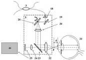
图1 人眼视网膜血流测量装置示意图;Fig.1 Schematic diagram of retinal blood flow measurement device in human eye;
图2干涉仪参考臂结构示意图;Fig. 2 is a schematic diagram of the structure of the reference arm of the interferometer;
图3 视网膜血流测量装置眼底扫描单元结构示意图Figure 3 Schematic diagram of the fundus scanning unit of the retinal blood flow measurement device
图4 视网膜血流测量装置探测器结构示意图Figure 4 Schematic diagram of the detector structure of the retinal blood flow measurement device
图5 光束通过人眼前焦点扫描眼底示意图Figure 5 Schematic diagram of the light beam scanning the fundus through the focus of the human eye
图6 视网膜分区示意图Figure 6 Schematic diagram of retinal divisions
图7 视场上边缘光束扫描示意图Figure 7. Schematic diagram of the upper edge beam scanning in the field of view
图8 视场中心部位光束扫描示意图Figure 8 Schematic diagram of beam scanning at the center of the field of view
图9视场下边缘光束扫描示意图Fig. 9 Schematic diagram of scanning edge beam in the lower field of view
图10 (a)视网膜血管两次扫描示意图;(b)多普勒角示意图Figure 10 (a) Schematic diagram of two scans of retinal blood vessels; (b) schematic diagram of Doppler angle
具体实施方式Detailed ways
下面结合附图对本发明进行详细的介绍。The present invention will be described in detail below with reference to the accompanying drawings.
本实施方式提供了一种新型的基于单光束OCT系统的视网膜血流测量装置,该测量装置的具体结构见图1,它由光源1、光学隔离器2、光纤分束器3、参考光路单元4、光束扫描单元5、光谱仪单元6以及数据采集控制单元7构成。其中,光源1为一宽带近红外光源,例如超辐射发光二极管(SLD)。光源1发出的光通过光学隔离器2与光纤耦合器3的入射端口连接,光源1的光经过光纤耦合器3分别进入参考光路单元4和光束扫描单元5,由光束扫描单元5返回的样品光信号通过光纤耦合器3进入光谱仪单元6接收光信号;数据采集控制单元7分别与光束扫描单元5和光谱仪单元6电连接。This embodiment provides a novel retinal blood flow measurement device based on a single-beam OCT system. The specific structure of the measurement device is shown in Figure 1. It consists of a
参考光路单元4的具体结构参见图2,包含第一参考臂34和第二参考臂35,第一参考臂34包括第二准直透镜9、光强衰减器10、第一光路开关12和第一全反射镜13;所述第二参考臂35包括所述第二准直透镜9、所述光强衰减器10、半透半反镜11、第二光路开关17和第二全反射镜15。由光源输出的光经过光纤分束器3后,一路进入参考光路单元4。进入参考光路单元4的光经过一个偏振控制器8后,被第二准直透镜9准直,然后通过一个光强衰减器10,入射到半透半反镜11上面。通过调节偏振控制器8,实现参考光和样品信号光之间的偏振态匹配;光强衰减器10用于控制参考光路的光强在合理的范围。一部分光通过半透半反镜11,经过光路开关12入射到第一全反射镜13上,第二准直透镜9和第一全返射镜13构成干涉仪的第一参考臂34,第一光路开关12用以控制第一参考臂34光路的开关和闭合。第一全反射镜13安装在第一一维移动台14上面,可以沿入射光方向前后移动以调整第一参考臂34的光程。入射到半透半反镜11上面的另一部分光由半透半反镜11反射,经过第二光路开关17,入射到第二全反射镜15表面。当光路开关17闭合,光路开关12打开时,第一参考臂34工作,探测光通过人眼前焦点进入人眼21,以平行于人眼21的光轴或辐轴的方式对视网膜进行扫描。第二准直透镜9、半透半反镜11、第二光路开关17和第二全反射镜15构成第二参考臂35,第二光路开关17用以控制第二参考臂35光路的开关和闭合。第二全反射镜15安装在第二一维移动台16上面,可以沿入射光方向前后移动以调整第二参考臂35的光程。通过对正常人眼的光学结构进行ZEMAX模拟计算可知,人眼前焦点到瞳孔中心的几何距离约为17.13毫米, 因此,第一参考臂34的光程长度比第二参考臂35的光程长度要长17.13毫米。Refer to FIG. 2 for the specific structure of the reference optical path unit 4, which includes a first reference arm 34 and a second reference arm 35. The first reference arm 34 includes a
光束扫描单元5的具体结构见图3,包括与光纤耦合器3连接的第一准直透镜18,与第一准直透镜18连接的第一反射镜19、与第一反射镜19连接的二维扫描振镜26,以及与二维扫描振镜26连接的第一透镜20、第二反射镜23和第二透镜22。由光纤分束器3输出的另一路光经由第一准直透镜18准直以后,被第一反射镜19反射到一个二维扫描振镜26。由二维扫描振镜26反射的光,经由第一透镜20入射到第二反射镜23上, 第二反射镜23为一双色反射镜,对840nm的近红外光具有高的反射率,对可见光具有高的透射率。被第二反射镜23反射的探测光经由第二透镜22进入人眼21中,对视网膜进行扫描检测。在光束扫描单元5中,还包含一个液晶显示屏定位靶25,它可以产生一个可见光波段的十字叉,例如绿色,定位靶25上十字叉的位置通过计算机进行控制。由定位靶25产生的十字叉经过第三透镜24、第二反射镜23和第二透镜22投影到人眼21的视网膜上。在OCT扫描过程中,被测人眼通过观察定位靶25上上不同位置的十字叉图像,可以防止人眼的抖动并对扫描位置进行定位,实现对视网膜不同部位的扫描。The specific structure of the beam scanning unit 5 is shown in FIG. 3 , including a
光谱仪单元6的具体结构参见图4。包括第三准直透镜27、光栅28、聚焦透镜29和线阵CCD 30,经过光纤耦合器3干涉的光进入光谱仪单元6,经由第三准直透镜27准直以后,入射到一个透射型衍射光栅28上,干涉信号的不同光谱成分经过衍射光栅28以后,被聚焦透镜29成像在一个线阵CCD30上,线阵CCD30输出的电信号由图像采集卡31进行采集。The specific structure of the spectrometer unit 6 is shown in FIG. 4 . Including the
参见图1,数据采集控制单元7由图像采集卡31、扫描驱动卡32和计算机33组成。图像采集卡31与光谱仪单元6中的信号接收装置电连接,扫描驱动卡32与二维扫描振镜26的角度偏转装置电连接;图像采集卡31采集光谱仪单元6中的信号接收装置接收的干涉光谱信号后传输至计算机33处理,并发出驱动控制信号传输给扫描驱动卡32,扫描驱动卡32控制二维扫描振镜26的角度偏转,图像采集卡31采集到的光谱干涉信号由计算机33接收并进行处理。Referring to FIG. 1 , the data acquisition control unit 7 is composed of an
工作原理:working principle:
(1)光束平行扫描模式的实现(1) Realization of beam parallel scanning mode
参见图1,由光源1发出的宽带光,经过光学隔离器2和光纤分束器3以后被分为两路,一路光进入参考光路4,另一路光进入光束扫描单元5。1, the broadband light emitted by the
参见图2,首先打开第二参考臂35 中的第二光路开关17,同时第一参考臂34中的第一光路开关12关闭。然后,扫描光束按传统方法通过人眼的瞳孔中心,进入人眼21,按设定的扫描宽度,对人眼21的视网膜扫描成像,得到眼底视盘部位的结构图T1,这张图的宽度将作为下一步测量的标尺。然后打开第一参考臂34 中的第一光路开关12,同时第二参考臂35中的第二光路开关17关闭。Referring to FIG. 2 , first the second
参见图3,将扫描单元5整体向远离人眼的方向移动,使得扫描物镜22的焦点F向后移动到眼睛前焦点的位置,当F和人眼表面的距离d约为17.13毫米时,在眼睛内部,探测光束将以近似平行于光轴的方式对视网膜进行扫描。对人眼21的视网膜进行扫描成像,得到眼底视盘部位的结构图T2,将图T2 和T1 进行对比,可以对平行扫描模式的尺度进行定标。Referring to FIG. 3, the scanning unit 5 is moved as a whole in a direction away from the human eye, so that the focal point F of the scanning
(2)视网膜不同部位血管的扫描(2) Scanning of blood vessels in different parts of the retina
参见图5,在平行扫描模式下,在视网膜上不同高度H处(假定血管沿着球面分布),入射光束和视网膜血管之间夹角为α=cos-1(H/R),其中R为视网膜视场中心区的曲率半径,约为16.5毫米。在H=2.5毫米时,角度为81.3度,可以实现该位置视网膜血管血流的有效测量。Referring to Figure 5, in parallel scanning mode, at different heights H on the retina (assuming that the blood vessels are distributed along a spherical surface), the angle between the incident beam and the retinal blood vessels is α=cos-1 (H/R), where R is The radius of curvature of the central area of the retinal field of view, approximately 16.5 mm. When H=2.5 mm, the angle is 81.3 degrees, which can effectively measure the blood flow of retinal blood vessels at this position.
参见图6,以黄斑中心和视盘中心所在的平面为例,人眼21的视网膜被分为四个区间a1、a2、a3和a4。以黄斑中心为竖直方向的坐标原点,区间a2对应的视网膜高度ha2为0≤ha2≤2.5毫米,区间a1对应的视网膜区间高度ha1≥2.5毫米,区间a3对应的视网膜区间高度ha3为-2.5毫米≤ha3≤0,区间a4对应的视网膜区间高度ha4≤-2.5毫米。Referring to FIG. 6 , taking the plane where the center of the macula and the center of the optic disc are located as an example, the retina of the
参见图3,为了实现对视网膜上不同部位血管的倾斜角度入射,我们使用一个带有十字叉的定位靶25来调节眼球的转动。参见图7,探测光首先沿光路方向I 进行,对于视网膜区间a1,将定位靶25上的十字叉在平面内向上移动,通过转动眼球观察十字叉,在不改变光束扫描方向的情况下,就可以对视网膜区间a1中的血管进行扫描测量。类似的,参见图8,将定位靶25上的十字叉向下移,通过转动眼球观察十字叉,眼轴向下转动,在不改变光束扫描方向的情况下,就可以对视网膜区间a2中的血管进行扫描测量。Referring to Fig. 3, in order to achieve oblique angles of incidence to blood vessels in different parts of the retina, we use a
参见图9,首先通过控制二维扫描振镜26,使得探测光束以光路II方向进入人眼,接下来,将定位靶25上的十字叉向上移动,通过转动眼球观察十字叉,在不改变光束方向II的情况下,就可以对视网膜区间a3中的血管进行扫描测量。类似的,将定位靶25上的十字叉向下移动,通过转动眼球观察十字叉,在不改变光束方向II的情况下,可以实现对视网膜区间a4中的血管进行扫描测量。因此,通过控制扫描光束路径以及相应的调整定位靶25上十字叉的位置,可以对视网膜上以黄斑为中心,直径大于10毫米区域内的血管进行倾斜扫描,从而实现对人眼视网膜血管分支血流的有效定量测量。Referring to FIG. 9, firstly, by controlling the two-
(3)多普勒角度的确定及血流计算(3) Determination of Doppler angle and calculation of blood flow
参见图10(a),探测光束首先沿着实线路径L1进入人眼,扫描获得一幅待测视网膜血管的图像,如图10(b)中血管图1的实线圆所示,血管中心C1的坐标为(x1,y1,z1),这个扫描被称为第一次扫描;然后,二维扫描振镜26转动到虚线所示位置,探测光束沿着虚线路径L2进入人眼,扫描待测视网膜血管获得另一幅图像,如图10(b)中的虚线圆所示,血管中心C2的坐标为(x2,y2,z2),这个扫描被称为第二次扫描。在血管上,第二次扫描的位置相对于第一次扫描有一个微小的平移。Referring to Figure 10(a), the detection beamfirst enters the human eye along the solid line path L1, and scans to obtain an image of the retinal blood vessel to be measured, as shown by the solid line circle in Figure 1 of the blood vessel in Figure 10(b), the center of the blood vessel is The coordinates of C1 are (x1 , y1 , z1 ), and this scan is called the first scan; then, the two-
参见图10(b),由两次扫描获得的血管中心C1和C2的位置坐标,可以计算出血管的方向矢量r,而OCT 扫描光束的方向矢量为z,则扫描光束和血管之间夹角α满足Referring to Figure 10(b), the position coordinates of the blood vessel centers C1 and C2 obtained by two scans can calculate the direction vector r of the blood vessel, and the direction vector of the OCT scanning beam is z, then the scanning beam and the blood vessel are between the The included angle α is satisfied
cosα=(r·z)/S (2) cosα=(r·z)/S (2)
其中S为C1和C2之间的距离,可以通过它们的坐标计算出来。将(2)式的结果代入背景技术中的公式(1)中,可以计算出待测血管中的血流速度V。得到血流速度以后,血管中的血液流量BF为BF=V×A,其中A为血管的横截面积,可以通过待测血管的OCT图像计算出来。where S is the distance betweenC1 andC2 , which can be calculated from their coordinates. Substituting the result of formula (2) into formula (1) in the background art, the blood flow velocity V in the blood vessel to be measured can be calculated. After the blood flow velocity is obtained, the blood flow BF in the blood vessel is BF=V×A, where A is the cross-sectional area of the blood vessel, which can be calculated from the OCT image of the blood vessel to be measured.
上述实施方式只为说明本发明的技术构思及特点,其目的在于让熟悉此项技术的人能够了解本发明的内容并据以实施,并不能以此限制本发明的保护范围。凡根据本发明精神实质所做的等效变换或修饰,都应涵盖在本发明的保护范围之内。The above-mentioned embodiments are only intended to illustrate the technical concept and features of the present invention, and the purpose is to enable those who are familiar with the art to understand the content of the present invention and implement it accordingly, and cannot limit the protection scope of the present invention. All equivalent transformations or modifications made according to the spirit of the present invention should be included within the protection scope of the present invention.
Claims (10)
Translated fromChinesePriority Applications (1)
| Application Number | Priority Date | Filing Date | Title |
|---|---|---|---|
| CN202010100741.2ACN111265183B (en) | 2020-02-19 | 2020-02-19 | Retina blood flow measuring device based on light beam parallel scanning mode |
Applications Claiming Priority (1)
| Application Number | Priority Date | Filing Date | Title |
|---|---|---|---|
| CN202010100741.2ACN111265183B (en) | 2020-02-19 | 2020-02-19 | Retina blood flow measuring device based on light beam parallel scanning mode |
Publications (2)
| Publication Number | Publication Date |
|---|---|
| CN111265183A CN111265183A (en) | 2020-06-12 |
| CN111265183Btrue CN111265183B (en) | 2022-05-27 |
Family
ID=70991384
Family Applications (1)
| Application Number | Title | Priority Date | Filing Date |
|---|---|---|---|
| CN202010100741.2AActiveCN111265183B (en) | 2020-02-19 | 2020-02-19 | Retina blood flow measuring device based on light beam parallel scanning mode |
Country Status (1)
| Country | Link |
|---|---|
| CN (1) | CN111265183B (en) |
Families Citing this family (8)
| Publication number | Priority date | Publication date | Assignee | Title |
|---|---|---|---|---|
| CN112022085B (en)* | 2020-09-16 | 2022-04-15 | 中山大学 | Method for calculating blood vessel flow in retina |
| CN112711030A (en)* | 2020-12-21 | 2021-04-27 | 武汉光目科技有限公司 | Microscope area array sweep frequency measuring device and method |
| CN112587085A (en)* | 2021-03-04 | 2021-04-02 | 季华实验室 | Optical coherent imaging system |
| CN112587084A (en)* | 2021-03-04 | 2021-04-02 | 季华实验室 | Optical coherent imaging system with real-time adjustable imaging depth |
| JP2023040903A (en) | 2021-09-10 | 2023-03-23 | 株式会社トーメーコーポレーション | Ophthalmologic apparatus |
| JP2023130994A (en)* | 2022-03-08 | 2023-09-21 | 株式会社トーメーコーポレーション | Ophthalmic device |
| CN114903425B (en)* | 2022-05-06 | 2024-03-12 | 山东探微医疗技术有限公司 | Visible light OCT device and method for reducing eye gazing fatigue during focusing |
| CN119379803B (en)* | 2024-12-30 | 2025-04-22 | 山东大学 | Blood flow velocity calculation method, OCT system, medium, product and apparatus |
Citations (7)
| Publication number | Priority date | Publication date | Assignee | Title |
|---|---|---|---|---|
| CN101720205A (en)* | 2007-04-10 | 2010-06-02 | 南加利福尼亚大学 | Methods and systems for blood flow measurement using doppler optical coherence tomography |
| CN104825148A (en)* | 2015-05-27 | 2015-08-12 | 深圳市斯尔顿科技有限公司 | Device and method for measuring blood flow of blood vessels |
| CN105310677A (en)* | 2014-08-01 | 2016-02-10 | 深圳市斯尔顿科技有限公司 | Device and method for measuring blood flow rate |
| CN106510644A (en)* | 2016-12-29 | 2017-03-22 | 淮阴工学院 | Medical optical coherence tomography two-dimensional forward scanning probe based on fiber optics bundle |
| CN108572161A (en)* | 2018-04-10 | 2018-09-25 | 淮阴工学院 | Optical coherence tomography device based on split-wavefront interferometer |
| CN109124686A (en)* | 2018-09-11 | 2019-01-04 | 中山大学 | A kind of blood flow measurement device and method |
| CN109691975A (en)* | 2018-12-29 | 2019-04-30 | 佛山科学技术学院 | A kind of device and method of the cornea eye curvature measurement based on SD-OCT |
Family Cites Families (1)
| Publication number | Priority date | Publication date | Assignee | Title |
|---|---|---|---|---|
| US8879070B2 (en)* | 2009-06-11 | 2014-11-04 | University Of Tsukuba | Two beams formed by Wollaston prism in sample arm in an optical coherence tomography apparatus |
- 2020
- 2020-02-19CNCN202010100741.2Apatent/CN111265183B/enactiveActive
Patent Citations (7)
| Publication number | Priority date | Publication date | Assignee | Title |
|---|---|---|---|---|
| CN101720205A (en)* | 2007-04-10 | 2010-06-02 | 南加利福尼亚大学 | Methods and systems for blood flow measurement using doppler optical coherence tomography |
| CN105310677A (en)* | 2014-08-01 | 2016-02-10 | 深圳市斯尔顿科技有限公司 | Device and method for measuring blood flow rate |
| CN104825148A (en)* | 2015-05-27 | 2015-08-12 | 深圳市斯尔顿科技有限公司 | Device and method for measuring blood flow of blood vessels |
| CN106510644A (en)* | 2016-12-29 | 2017-03-22 | 淮阴工学院 | Medical optical coherence tomography two-dimensional forward scanning probe based on fiber optics bundle |
| CN108572161A (en)* | 2018-04-10 | 2018-09-25 | 淮阴工学院 | Optical coherence tomography device based on split-wavefront interferometer |
| CN109124686A (en)* | 2018-09-11 | 2019-01-04 | 中山大学 | A kind of blood flow measurement device and method |
| CN109691975A (en)* | 2018-12-29 | 2019-04-30 | 佛山科学技术学院 | A kind of device and method of the cornea eye curvature measurement based on SD-OCT |
Also Published As
| Publication number | Publication date |
|---|---|
| CN111265183A (en) | 2020-06-12 |
Similar Documents
| Publication | Publication Date | Title |
|---|---|---|
| CN111265183B (en) | Retina blood flow measuring device based on light beam parallel scanning mode | |
| US4761071A (en) | Apparatus and method for determining corneal and scleral topography | |
| US5644642A (en) | Gaze tracking using optical coherence tomography | |
| JP6196206B2 (en) | Multichannel optical coherence tomography | |
| JP5628177B2 (en) | Measuring system | |
| JP4287290B2 (en) | Measurement of optical properties | |
| EP3250956B1 (en) | Microscopy system with auto-focus adjustment by low-coherence interferometry | |
| JP5913424B2 (en) | Method and analyzer for eye examination | |
| JP2002516688A (en) | Eye test equipment using polarized probe | |
| CN1128131A (en) | Optical coherence tomography corneal mapping device | |
| JPH08508903A (en) | Retinal eye disease diagnostic system | |
| JPH08206086A (en) | Equipment and method for measuring speed of blood | |
| US10456033B2 (en) | Apparatus and method for measuring blood flow of vessels | |
| US9161687B2 (en) | Device for interferometrically measuring the eye length and the anterior eye segment | |
| CN106510644B (en) | Medical optical coherence chromatographic imaging two dimension scan forward probe based on fiber optic bundle | |
| US11154192B2 (en) | Method and arrangement for high-resolution topography of the cornea of an eye | |
| CN106725287B (en) | A kind of non-cpntact measurement device and method of ocular biometric parameters | |
| WO2015172322A1 (en) | Blood flow measuring device and method | |
| WO2022062049A1 (en) | Beam splitter-based imaging device integrating anterior segment oct and biometer functions | |
| US20160045106A1 (en) | Multi-Channel Optical Coherence Tomography | |
| US6454722B1 (en) | Doppler velocimeter for blood flow | |
| CN113995374A (en) | A kind of whole eyeball three-dimensional imaging device and method | |
| US11497397B2 (en) | Ophthalmologic apparatus | |
| CN210130811U (en) | Multi-parameter and multi-functional eye measuring instrument based on optical coherence tomography | |
| RU187692U1 (en) | Device for endoscopic optical coherence tomography with wavefront correction |
Legal Events
| Date | Code | Title | Description |
|---|---|---|---|
| PB01 | Publication | ||
| PB01 | Publication | ||
| SE01 | Entry into force of request for substantive examination | ||
| SE01 | Entry into force of request for substantive examination | ||
| GR01 | Patent grant | ||
| GR01 | Patent grant |