CN111263626A - Exoskeleton fitting degree evaluation system and method - Google Patents
Exoskeleton fitting degree evaluation system and methodDownload PDFInfo
- Publication number
- CN111263626A CN111263626ACN201880056518.3ACN201880056518ACN111263626ACN 111263626 ACN111263626 ACN 111263626ACN 201880056518 ACN201880056518 ACN 201880056518ACN 111263626 ACN111263626 ACN 111263626A
- Authority
- CN
- China
- Prior art keywords
- user
- actuator unit
- leg
- configuration
- fit
- Prior art date
- Legal status (The legal status is an assumption and is not a legal conclusion. Google has not performed a legal analysis and makes no representation as to the accuracy of the status listed.)
- Granted
Links
Images


Classifications
- A—HUMAN NECESSITIES
- A61—MEDICAL OR VETERINARY SCIENCE; HYGIENE
- A61H—PHYSICAL THERAPY APPARATUS, e.g. DEVICES FOR LOCATING OR STIMULATING REFLEX POINTS IN THE BODY; ARTIFICIAL RESPIRATION; MASSAGE; BATHING DEVICES FOR SPECIAL THERAPEUTIC OR HYGIENIC PURPOSES OR SPECIFIC PARTS OF THE BODY
- A61H3/00—Appliances for aiding patients or disabled persons to walk about
- A—HUMAN NECESSITIES
- A61—MEDICAL OR VETERINARY SCIENCE; HYGIENE
- A61H—PHYSICAL THERAPY APPARATUS, e.g. DEVICES FOR LOCATING OR STIMULATING REFLEX POINTS IN THE BODY; ARTIFICIAL RESPIRATION; MASSAGE; BATHING DEVICES FOR SPECIAL THERAPEUTIC OR HYGIENIC PURPOSES OR SPECIFIC PARTS OF THE BODY
- A61H1/00—Apparatus for passive exercising; Vibrating apparatus; Chiropractic devices, e.g. body impacting devices, external devices for briefly extending or aligning unbroken bones
- A61H1/02—Stretching or bending or torsioning apparatus for exercising
- A61H1/0237—Stretching or bending or torsioning apparatus for exercising for the lower limbs
- A61H1/024—Knee
- A—HUMAN NECESSITIES
- A61—MEDICAL OR VETERINARY SCIENCE; HYGIENE
- A61H—PHYSICAL THERAPY APPARATUS, e.g. DEVICES FOR LOCATING OR STIMULATING REFLEX POINTS IN THE BODY; ARTIFICIAL RESPIRATION; MASSAGE; BATHING DEVICES FOR SPECIAL THERAPEUTIC OR HYGIENIC PURPOSES OR SPECIFIC PARTS OF THE BODY
- A61H1/00—Apparatus for passive exercising; Vibrating apparatus; Chiropractic devices, e.g. body impacting devices, external devices for briefly extending or aligning unbroken bones
- A61H1/02—Stretching or bending or torsioning apparatus for exercising
- A61H1/0237—Stretching or bending or torsioning apparatus for exercising for the lower limbs
- A61H1/0266—Foot
- B—PERFORMING OPERATIONS; TRANSPORTING
- B25—HAND TOOLS; PORTABLE POWER-DRIVEN TOOLS; MANIPULATORS
- B25J—MANIPULATORS; CHAMBERS PROVIDED WITH MANIPULATION DEVICES
- B25J19/00—Accessories fitted to manipulators, e.g. for monitoring, for viewing; Safety devices combined with or specially adapted for use in connection with manipulators
- B25J19/0095—Means or methods for testing manipulators
- B—PERFORMING OPERATIONS; TRANSPORTING
- B25—HAND TOOLS; PORTABLE POWER-DRIVEN TOOLS; MANIPULATORS
- B25J—MANIPULATORS; CHAMBERS PROVIDED WITH MANIPULATION DEVICES
- B25J9/00—Programme-controlled manipulators
- B25J9/0006—Exoskeletons, i.e. resembling a human figure
- B—PERFORMING OPERATIONS; TRANSPORTING
- B25—HAND TOOLS; PORTABLE POWER-DRIVEN TOOLS; MANIPULATORS
- B25J—MANIPULATORS; CHAMBERS PROVIDED WITH MANIPULATION DEVICES
- B25J9/00—Programme-controlled manipulators
- B25J9/10—Programme-controlled manipulators characterised by positioning means for manipulator elements
- B25J9/14—Programme-controlled manipulators characterised by positioning means for manipulator elements fluid
- B25J9/142—Programme-controlled manipulators characterised by positioning means for manipulator elements fluid comprising inflatable bodies
- A—HUMAN NECESSITIES
- A61—MEDICAL OR VETERINARY SCIENCE; HYGIENE
- A61H—PHYSICAL THERAPY APPARATUS, e.g. DEVICES FOR LOCATING OR STIMULATING REFLEX POINTS IN THE BODY; ARTIFICIAL RESPIRATION; MASSAGE; BATHING DEVICES FOR SPECIAL THERAPEUTIC OR HYGIENIC PURPOSES OR SPECIFIC PARTS OF THE BODY
- A61H2201/00—Characteristics of apparatus not provided for in the preceding codes
- A61H2201/12—Driving means
- A61H2201/1238—Driving means with hydraulic or pneumatic drive
- A—HUMAN NECESSITIES
- A61—MEDICAL OR VETERINARY SCIENCE; HYGIENE
- A61H—PHYSICAL THERAPY APPARATUS, e.g. DEVICES FOR LOCATING OR STIMULATING REFLEX POINTS IN THE BODY; ARTIFICIAL RESPIRATION; MASSAGE; BATHING DEVICES FOR SPECIAL THERAPEUTIC OR HYGIENIC PURPOSES OR SPECIFIC PARTS OF THE BODY
- A61H2201/00—Characteristics of apparatus not provided for in the preceding codes
- A61H2201/16—Physical interface with patient
- A61H2201/1602—Physical interface with patient kind of interface, e.g. head rest, knee support or lumbar support
- A61H2201/164—Feet or leg, e.g. pedal
- A61H2201/1642—Holding means therefor
- A—HUMAN NECESSITIES
- A61—MEDICAL OR VETERINARY SCIENCE; HYGIENE
- A61H—PHYSICAL THERAPY APPARATUS, e.g. DEVICES FOR LOCATING OR STIMULATING REFLEX POINTS IN THE BODY; ARTIFICIAL RESPIRATION; MASSAGE; BATHING DEVICES FOR SPECIAL THERAPEUTIC OR HYGIENIC PURPOSES OR SPECIFIC PARTS OF THE BODY
- A61H2201/00—Characteristics of apparatus not provided for in the preceding codes
- A61H2201/16—Physical interface with patient
- A61H2201/1602—Physical interface with patient kind of interface, e.g. head rest, knee support or lumbar support
- A61H2201/165—Wearable interfaces
- A—HUMAN NECESSITIES
- A61—MEDICAL OR VETERINARY SCIENCE; HYGIENE
- A61H—PHYSICAL THERAPY APPARATUS, e.g. DEVICES FOR LOCATING OR STIMULATING REFLEX POINTS IN THE BODY; ARTIFICIAL RESPIRATION; MASSAGE; BATHING DEVICES FOR SPECIAL THERAPEUTIC OR HYGIENIC PURPOSES OR SPECIFIC PARTS OF THE BODY
- A61H2201/00—Characteristics of apparatus not provided for in the preceding codes
- A61H2201/16—Physical interface with patient
- A61H2201/1657—Movement of interface, i.e. force application means
- A61H2201/1676—Pivoting
- A—HUMAN NECESSITIES
- A61—MEDICAL OR VETERINARY SCIENCE; HYGIENE
- A61H—PHYSICAL THERAPY APPARATUS, e.g. DEVICES FOR LOCATING OR STIMULATING REFLEX POINTS IN THE BODY; ARTIFICIAL RESPIRATION; MASSAGE; BATHING DEVICES FOR SPECIAL THERAPEUTIC OR HYGIENIC PURPOSES OR SPECIFIC PARTS OF THE BODY
- A61H2201/00—Characteristics of apparatus not provided for in the preceding codes
- A61H2201/50—Control means thereof
- A61H2201/5007—Control means thereof computer controlled
- A—HUMAN NECESSITIES
- A61—MEDICAL OR VETERINARY SCIENCE; HYGIENE
- A61H—PHYSICAL THERAPY APPARATUS, e.g. DEVICES FOR LOCATING OR STIMULATING REFLEX POINTS IN THE BODY; ARTIFICIAL RESPIRATION; MASSAGE; BATHING DEVICES FOR SPECIAL THERAPEUTIC OR HYGIENIC PURPOSES OR SPECIFIC PARTS OF THE BODY
- A61H2201/00—Characteristics of apparatus not provided for in the preceding codes
- A61H2201/50—Control means thereof
- A61H2201/5058—Sensors or detectors
- A61H2201/5061—Force sensors
- A—HUMAN NECESSITIES
- A61—MEDICAL OR VETERINARY SCIENCE; HYGIENE
- A61H—PHYSICAL THERAPY APPARATUS, e.g. DEVICES FOR LOCATING OR STIMULATING REFLEX POINTS IN THE BODY; ARTIFICIAL RESPIRATION; MASSAGE; BATHING DEVICES FOR SPECIAL THERAPEUTIC OR HYGIENIC PURPOSES OR SPECIFIC PARTS OF THE BODY
- A61H2201/00—Characteristics of apparatus not provided for in the preceding codes
- A61H2201/50—Control means thereof
- A61H2201/5058—Sensors or detectors
- A61H2201/5064—Position sensors
- A—HUMAN NECESSITIES
- A61—MEDICAL OR VETERINARY SCIENCE; HYGIENE
- A61H—PHYSICAL THERAPY APPARATUS, e.g. DEVICES FOR LOCATING OR STIMULATING REFLEX POINTS IN THE BODY; ARTIFICIAL RESPIRATION; MASSAGE; BATHING DEVICES FOR SPECIAL THERAPEUTIC OR HYGIENIC PURPOSES OR SPECIFIC PARTS OF THE BODY
- A61H2201/00—Characteristics of apparatus not provided for in the preceding codes
- A61H2201/50—Control means thereof
- A61H2201/5058—Sensors or detectors
- A61H2201/5069—Angle sensors
- A—HUMAN NECESSITIES
- A61—MEDICAL OR VETERINARY SCIENCE; HYGIENE
- A61H—PHYSICAL THERAPY APPARATUS, e.g. DEVICES FOR LOCATING OR STIMULATING REFLEX POINTS IN THE BODY; ARTIFICIAL RESPIRATION; MASSAGE; BATHING DEVICES FOR SPECIAL THERAPEUTIC OR HYGIENIC PURPOSES OR SPECIFIC PARTS OF THE BODY
- A61H2201/00—Characteristics of apparatus not provided for in the preceding codes
- A61H2201/50—Control means thereof
- A61H2201/5058—Sensors or detectors
- A61H2201/5084—Acceleration sensors
- A—HUMAN NECESSITIES
- A61—MEDICAL OR VETERINARY SCIENCE; HYGIENE
- A61H—PHYSICAL THERAPY APPARATUS, e.g. DEVICES FOR LOCATING OR STIMULATING REFLEX POINTS IN THE BODY; ARTIFICIAL RESPIRATION; MASSAGE; BATHING DEVICES FOR SPECIAL THERAPEUTIC OR HYGIENIC PURPOSES OR SPECIFIC PARTS OF THE BODY
- A61H2203/00—Additional characteristics concerning the patient
- A61H2203/04—Position of the patient
- A61H2203/0406—Standing on the feet
- A—HUMAN NECESSITIES
- A61—MEDICAL OR VETERINARY SCIENCE; HYGIENE
- A61H—PHYSICAL THERAPY APPARATUS, e.g. DEVICES FOR LOCATING OR STIMULATING REFLEX POINTS IN THE BODY; ARTIFICIAL RESPIRATION; MASSAGE; BATHING DEVICES FOR SPECIAL THERAPEUTIC OR HYGIENIC PURPOSES OR SPECIFIC PARTS OF THE BODY
- A61H2205/00—Devices for specific parts of the body
- A61H2205/10—Leg
Landscapes
- Health & Medical Sciences (AREA)
- Engineering & Computer Science (AREA)
- Life Sciences & Earth Sciences (AREA)
- Public Health (AREA)
- Epidemiology (AREA)
- Pain & Pain Management (AREA)
- Physical Education & Sports Medicine (AREA)
- Rehabilitation Therapy (AREA)
- Veterinary Medicine (AREA)
- Animal Behavior & Ethology (AREA)
- General Health & Medical Sciences (AREA)
- Mechanical Engineering (AREA)
- Robotics (AREA)
- Manipulator (AREA)
- Rehabilitation Tools (AREA)
- Prostheses (AREA)
- Stacking Of Articles And Auxiliary Devices (AREA)
- Automobile Manufacture Line, Endless Track Vehicle, Trailer (AREA)
- Investigating Strength Of Materials By Application Of Mechanical Stress (AREA)
Abstract
Translated fromChinese
Description
Translated fromChinese相关申请的交叉引用CROSS-REFERENCE TO RELATED APPLICATIONS
本申请要求2017年8月29日提交的美国临时申请号62/551,664的权益,所述申请出于所有目的特此以引用的方式整体并入本文。This application claims the benefit of US Provisional Application No. 62/551,664, filed August 29, 2017, which is hereby incorporated by reference in its entirety for all purposes.
本申请还涉及2018年4月13日提交的美国专利申请号15/953,296,并且涉及2017年11月27日提交的美国专利申请号15/823,523,并且涉及2016年3月28日提交的美国专利申请号15/082,824,所述申请也出于所有目的特此以引用的方式整体并入本文。This application is also related to US Patent Application No. 15/953,296, filed April 13, 2018, and to US Patent Application No. 15/823,523, filed November 27, 2017, and to US Patent Application No. 15/823,523, filed March 28, 2016 Application No. 15/082,824, which is also hereby incorporated by reference in its entirety for all purposes.
背景技术Background technique
带动力的外骨骼装置的性能可能会直接受到其如何良好地贴合用户的影响。不良贴合的装置的性能可能会明显不如适当贴合的装置。用于解决这个问题的两种常规选项是专业人员配合和大量训练材料。专业人员配合无法用于超过严格控制的设定中,并且即使经过大量训练,普通用户也可能会遇到配合的难题。鉴于前述内容,需要一种用于自动地评定外骨骼装置对用户贴合的质量以便在不需要专业人员配合的情况下维持高级别性能的改进的装置。The performance of a powered exoskeleton device may be directly affected by how well it fits the user. A poorly fitted device may perform significantly worse than a properly fitted device. Two general options for solving this problem are professional cooperation and extensive training materials. Professional coordination cannot be used in settings beyond tight control, and even with extensive training, the average user may experience coordination difficulties. In view of the foregoing, there is a need for an improved device for automatically assessing the quality of the fit of an exoskeleton device to a user in order to maintain a high level of performance without the need for professional cooperation.
附图说明Description of drawings
图1是由用户穿戴的外骨骼系统的实施方案的示例图示。1 is an example illustration of an embodiment of an exoskeleton system worn by a user.
图2是由用户在滑雪时穿戴的外骨骼系统的另一个实施方案的示例图示。2 is an example illustration of another embodiment of an exoskeleton system worn by a user while skiing.
图3是由用户在滑雪时穿戴的外骨骼系统的另一实施方案的示例图示。3 is an example illustration of another embodiment of an exoskeleton system worn by a user while skiing.
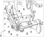
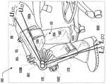
图4a和图4b是穿戴在用户的腿上的外骨骼系统的又一个实施方案的示例图示。Figures 4a and 4b are example illustrations of yet another embodiment of an exoskeleton system worn on a user's leg.
图5是示出外骨骼系统的实施方案的框图。5 is a block diagram illustrating an embodiment of an exoskeleton system.
图6a示出了在贴合度测试期间由用户穿戴的外骨骼系统,所述外骨骼系统处于未致动状态。Figure 6a shows the exoskeleton system worn by the user during a fit test in an unactuated state.
图6b示出了在贴合度测试期间处于致动状态的图6a的外骨骼系统,所述致动状态产生了外骨骼系统的上臂的位移。Figure 6b shows the exoskeleton system of Figure 6a during a fit test in an actuated state that produces displacement of the upper arm of the exoskeleton system.
图7a示出了在贴合度测试期间由用户穿戴的外骨骼系统,所述外骨骼系统处于未致动状态。Figure 7a shows the exoskeleton system worn by the user during a fit test in an unactuated state.
图7b示出了在贴合度测试期间处于致动状态的图7a的外骨骼系统,所述致动状态产生了外骨骼系统的上臂和下臂的位移。Figure 7b shows the exoskeleton system of Figure 7a during a fit test in an actuated state that produces displacement of the upper and lower arms of the exoskeleton system.
图8示出了根据一个实施方案的一种执行静止贴合度测试的方法。Figure 8 illustrates a method of performing a static fit test, according to one embodiment.
图9示出了根据一个实施方案的一种执行移动贴合度测试的方法。9 illustrates a method of performing a mobile fit test, according to one embodiment.
应注意,附图未按比例绘制,并且出于说明目的,类似结构或功能的元件贯穿附图通常由相似附图标记表示。还应注意,附图仅意图有助于对优选实施方案的描述。附图并未示出所描述的实施方案的每个方面并且不限制本公开的范围。It should be noted that the figures are not drawn to scale and that, for illustration purposes, elements of similar structure or function are generally designated by similar reference numerals throughout the figures. It should also be noted that the drawings are only intended to assist in the description of the preferred embodiments. The drawings do not illustrate every aspect of the described embodiments and do not limit the scope of the disclosure.
具体实施方式Detailed ways
在一个方面,本申请公开了涉及穿戴式动力装置(例如,外骨骼)的使用的示例实施方案,所述穿戴式动力装置被配置成自动地评估装置对用户贴合的合适性。动力装置对其用户的性能可以取决于所述装置如何良好地贴合用户的身体。不当贴合可能会降低性能,并且当前不存在解决这一点的超越较好的训练材料和专家指导的选项。本公开提出了一种用于控制装置以自动地评估装置贴合的质量并向用户提出潜在问题和解决方案的系统和方法。In one aspect, the present application discloses example embodiments involving the use of a wearable power device (eg, an exoskeleton) configured to automatically assess the suitability of the device for a user's fit. The performance of a powered device to its user may depend on how well the device fits the user's body. Improper fit can reduce performance, and there are currently no options for addressing this beyond better training materials and expert guidance. The present disclosure presents a system and method for controlling a device to automatically assess the quality of device fit and suggest potential problems and solutions to a user.
在一个方面,本公开教导了使用带动力的外骨骼装置来评估其自身对用户的贴合度的示例方法。例如,这可以通过解释传感器对用户身上的适当控制的机械动力的施加的响应来完成。下文详述了这类方法和实施这类贴合方法的系统的各种实施方案。出于本公开的目的,一些描述会考虑与带动力的膝盖外骨骼交互的用户场景。这样做是为了方便起见,并且决不限制本方法在人类或非人身体的其他部位上的其他穿戴式动力装置中的应用。In one aspect, the present disclosure teaches an example method of using a powered exoskeleton device to assess its own fit to a user. This can be done, for example, by interpreting the sensor's response to the application of an appropriately controlled mechanical force on the user. Various embodiments of such methods and systems for implementing such bonding methods are detailed below. For the purposes of this disclosure, some descriptions will consider user scenarios for interacting with a powered knee exoskeleton. This is done for convenience and in no way limits the application of the method to other wearable powered devices on other parts of the human or non-human body.
在其他方面,本公开涉及被设计用于评定外骨骼对用户的贴合度的系统和方法。各种实施方案被配置成在外骨骼装置和用户处于已知的形态时评估外骨骼装置响应于机械动力的系统输入而进行的运动。在一些实施方案中,这可以涉及在装置起动期间运行的计划中的贴合度测试或在装置操作期间的有意触发的测试。然而,其他实施方案可以针对本方法应用的定时使用设计思路。其他实施方案可以包括但不限于以下定时方法中的一者或多者:当所述装置进入在操作期间偶尔会遇到的一种特定状态时,在操作期间间歇地比较无动力行为与动力行为;在操作期间经常会遇到的装置构型下重复地比较无动力行为与动力行为;在相同的机械动力输入条件下,连续地比较先前的装置操作与当前的装置操作以评估随时间变化的偏差;等等。In other aspects, the present disclosure relates to systems and methods designed to assess the fit of an exoskeleton to a user. Various embodiments are configured to assess movement of the exoskeleton device in response to system inputs of mechanical power when the exoskeleton device and the user are in a known configuration. In some embodiments, this may involve a planned fit test run during device startup or an intentionally triggered test during device operation. However, other embodiments may use design considerations for the timing of application of the present method. Other embodiments may include, but are not limited to, one or more of the following timing methods: intermittently comparing unpowered versus powered behavior during operation when the device enters a particular state that is occasionally encountered during operation ; Repeatedly compare unpowered versus powered behavior under device configurations frequently encountered during operation; and continuously compare previous and current device operation under the same mechanical power input conditions to assess time-varying deviation; etc.
一个实施方案包括一种确定用于滑雪的膝盖外骨骼是否适当地贴合用户的腿的方法。应当说明的是,对这个示例实施方案的描述是为了清楚起见,而不意图以任何方式限制其他实施方案的应用。在一个示例实施方案中,被设计成在滑雪应用期间辅助膝盖的带动力的膝盖外骨骼可以被穿戴在用户的两条腿上,其中相应的腿外骨骼单元机械地连接到用户的相应的大腿和小腿。例如,在起动时,外骨骼装置可以指导用户进入就座姿势,其中膝盖在用户的前面弯曲,而脚牢牢地固定到地面。可以通过手机上的视觉提示或以其他合适的方式指导用户采取这个姿势。One embodiment includes a method of determining whether a knee exoskeleton for skiing properly fits a user's leg. It should be noted that the description of this example embodiment is for the sake of clarity and is not intended to limit the application of other embodiments in any way. In one example embodiment, a powered knee exoskeleton designed to assist the knee during ski applications may be worn on both legs of a user, with respective leg exoskeleton units mechanically connected to the user's respective thighs and calves. For example, upon activation, the exoskeleton device can guide the user into a seated position, where the knees are bent in front of the user and the feet are firmly anchored to the ground. The user may be instructed to take this gesture through visual cues on the phone or in other suitable ways.
一旦处于所指示的姿势,用户就可以通过按钮按下来开始装置的自动贴合度评估。此时,所述装置可以在这种已知的无动力构型下记录传感器信号的基线。外骨骼装置之后可以开始通过其膝盖致动器引入辅助性膝盖扭矩。在这个实施方案中,可以设计贴合度评估,使得外骨骼装置缓慢地增加扭矩直到达到预定最大扭矩为止,在此之后扭矩缓慢地返回到零。在这个固定构型下进行动力输入的整个过程中,所述装置记录来自装置传感器的数据。所述装置之后可以将装置在扭矩作用下的行为与无扭矩构型进行比较以确定所述装置是否充分地连接到用户。在这个实施方案中,所述装置可以将来自无动力构型的膝盖角度的测量与来自动力构型的膝盖角度的测量进行比较。如果所述装置观测到超过无动力构型与动力构型之间的膝盖角度的预定偏差(例如,10度的差值),则所述装置可以确定装置没有恰当地贴合用户。这个确定可以假设用户的腿没有明显偏离初始就座姿势,如果假设成立,则这意味着来自动力输入的任何膝盖角度偏差都归因于所述装置相对于腿的运动,从而指示不当贴合。Once in the indicated posture, the user can initiate an automatic fit assessment of the device with a button press. At this point, the device can record a baseline of the sensor signal in this known unpowered configuration. The exoskeleton device can then begin to introduce assistive knee torque through its knee actuators. In this embodiment, the fit assessment can be designed such that the exoskeleton device slowly increases the torque until a predetermined maximum torque is reached, after which the torque slowly returns to zero. Throughout the power input in this fixed configuration, the device records data from the device sensors. The device may then compare the behavior of the device under torque to the no-torque configuration to determine whether the device is adequately connected to the user. In this embodiment, the device may compare measurements of knee angle from the unpowered configuration with measurements of knee angle from the powered configuration. If the device observes a predetermined deviation (eg, a difference of 10 degrees) of the knee angle between the unpowered configuration and the powered configuration, the device may determine that the device does not fit the user properly. This determination may assume that the user's legs are not significantly deviated from the initial seating position, which, if true, means that any knee angle deviation from the power input is due to movement of the device relative to the legs, indicating an improper fit.
另一个实施方案包括一种确定用于医学应用的膝盖外骨骼是否适当贴合的方法。在这种实施方案中,外骨骼装置可以包括单腿式膝盖外骨骼,所述单腿式膝盖外骨骼被设计成在行走步态的静止站立期期间提供膝盖扭矩辅助。在这个实施方案中,外骨骼装置可以使用腿在站立期中的构型作为已知的初始基线构型。站立期可以由用户的静止站立姿势指示。在这个实施方案中,当用户在身体上进入站立期时,所述装置通过传感器或用户对装置的输入识别到已进入站立期构型,然后记录基线传感器读数来测量所述装置的当前构型。所述装置之后可以施加小的扭矩以在站立期间为膝盖提供支撑。在所述装置开始添加这种动力时,所述装置可以通过传感器测量监测装置的构型,然后可以将所述动力测量与基线构型测量进行比较。Another embodiment includes a method of determining whether a knee exoskeleton for medical applications fits properly. In such embodiments, the exoskeleton device may comprise a single-leg knee exoskeleton designed to provide knee torque assistance during the stationary stance phase of the walking gait. In this embodiment, the exoskeleton device may use the configuration of the legs in the stance phase as a known initial baseline configuration. The stance period may be indicated by the user's stationary standing posture. In this embodiment, when a user physically enters a stance phase, the device recognizes that a stance phase configuration has been entered through a sensor or user input to the device, and then records a baseline sensor reading to measure the device's current configuration . The device can then apply a small torque to provide support for the knee during standing. As the device begins to add such power, the device may monitor the configuration of the device through sensor measurements, which may then be compared to baseline configuration measurements.
在这个实施方案中,所述装置可以使用这些相对测量来完成两个主要贴合度评定。首先,所述装置可以评估因引入动力所致的膝盖角度的变化,并且可以确定系统是否不良地贴合。其次,所述装置可以识别最能指示装置的下杆或下臂没有适当地附接到用户的特定贴合问题,因此所述装置可以在动力构型期间特别检查所述装置的下杆的水平运动以确定所述下杆是否移动超过容许的范围。在各种实施方案中,用于检测膝盖角度误差的传感器和用于检测不期望的小腿运动的传感器可以是分开的和不同的。在评定和问题确定之后,所述装置可以根据识别到哪种贴合故障而向用户提供警告、警报等等(例如,“应当将装置条带上紧”或“应当将小腿条带上紧”)。In this embodiment, the device can use these relative measurements to complete two primary fit assessments. First, the device can assess the change in knee angle due to the introduction of power and can determine if the system is fitting poorly. Second, the device can identify specific fit issues that best indicate that the device's lower rod or lower arm is not properly attached to the user, so the device can specifically check the level of the device's lower rod during powered configuration Movement to determine if the lower rod has moved beyond an allowable range. In various embodiments, the sensor for detecting knee angle error and the sensor for detecting undesired calf motion may be separate and distinct. After assessment and problem determination, the device may provide a warning, alert, etc. to the user depending on which fit failure is identified (eg, "device straps should be tightened" or "calf straps should be tightened" ).
另一个实施方案包括一种评估用于步行应用的踝外骨骼的贴合度的方法。例如,所述装置可以在贯穿用户的步行步态的多个动态站立期中评估外骨骼装置对用户的贴合度。在一个实例中,当脚接触地面时,所述系统可以收集有关装置的构型和装置的初始无动力运动的初始测量。所述装置可以附接到用户的脚和小腿。Another embodiment includes a method of assessing the fit of an ankle exoskeleton for ambulatory applications. For example, the device may assess the fit of the exoskeleton device to the user during multiple dynamic stance sessions throughout the user's walking gait. In one example, when the foot contacts the ground, the system can collect initial measurements regarding the configuration of the device and the initial unpowered motion of the device. The device may be attached to the user's foot and lower leg.
在各种实例中的步行行为的动态站立期中,小腿主要围绕用户的踝关节旋转。因此,在这类实例中,所述装置的连接到小腿的部分应当以类似的方式主要围绕踝关节旋转。可以在检测到地面接触之后向踝外骨骼引入动力以辅助用户的步行行为。所述系统可以在此动力构型期间收集对所述装置的运动的测量。所述系统之后可以将动力传感器信号与无动力传感器信号进行比较。在这种实施方案中,可以进行比较来评估所述装置是否相对于小腿围绕踝关节以弧形方式适当地移动,或者所述装置是否沿用户的小腿向上平移。如果所述装置沿用户的腿向上平移超过阈值量,则外骨骼系统可以识别出已满足不良贴合标准或已达到不良贴合阈值,并且可以限制由所述装置施加的动力,同时发出用于提醒用户将小腿条带上紧的提示。During the dynamic stance phase of the walking behavior in various instances, the lower leg rotates primarily around the user's ankle joint. Thus, in such instances, the portion of the device that is connected to the lower leg should rotate primarily around the ankle joint in a similar manner. Power can be introduced to the ankle exoskeleton to assist the user's walking behavior after ground contact is detected. The system may collect measurements of the motion of the device during this powered configuration. The system may then compare the powered sensor signal with the unpowered sensor signal. In such an embodiment, a comparison can be made to assess whether the device moves in an arcuate fashion relative to the calf around the ankle joint properly, or whether the device translates up the user's calf. If the device is translated up the user's leg by more than a threshold amount, the exoskeleton system can identify that poor fit criteria have been met or that a poor fit threshold has been reached, and can limit the power applied by the device while issuing signals for A reminder to the user to tighten the calf straps.
在膝盖外骨骼的背景下提出了本公开的各种实例;然而,其他实施方案涉及其他穿戴式动力装置,所述其他穿戴式动力装置可以包括但不限于:膝盖外骨骼、踝外骨骼、髋外骨骼、肘外骨骼、肩外骨骼、腕外骨骼、背外骨骼、颈外骨骼、具有这些接合部、穿戴式装置、鞋以及更确切地说是主动鞋的任何组合的外骨骼。在穿戴式装置和鞋的情况下,在应用本方法时,动力添加不需要是接合部处的扭矩添加。在各种替代实施方案中,改变刚度或调整对用户的松紧度的装置也可以利用相同的系统和方法。Various examples of the present disclosure are presented in the context of knee exoskeletons; however, other embodiments relate to other wearable power devices, which may include, but are not limited to: knee exoskeletons, ankle exoskeletons, hip Exoskeletons, elbow exoskeletons, shoulder exoskeletons, wrist exoskeletons, dorsal exoskeletons, neck exoskeletons, exoskeletons having any combination of these joints, wearables, shoes, and more precisely active shoes. In the case of wearable devices and shoes, the power addition need not be a torque addition at the joint when applying the method. In various alternative embodiments, devices that vary stiffness or adjust tightness to the user may also utilize the same systems and methods.
转到图1,示出了由人类用户101穿戴的外骨骼系统100的实施方案的实例。如在这个实例中所示,外骨骼系统100包括分别联接到用户的左腿102L和右腿102R的左腿致动器单元110L和右腿致动器单元110R。在这个示例图示中,右腿致动器单元110R的多个部分被右腿102R遮蔽;然而,应当清楚的是,在各种实施方案中,左腿致动器单元110L和右腿致动器单元110R可以基本上是彼此的镜像。Turning to Figure 1, an example of an embodiment of an
腿致动器单元110可以包括经由接合部125可旋转地联接的上臂115和下臂120。波纹管致动器130在联接在上臂115和下臂120的相应端处的板140之间延伸,其中板140联接到接合部125的分开的可旋转部分。如本文更详细地所描述,多个约束肋135从接合部125延伸并且环绕波纹管致动器130的一部分。一组或多组气动管线145可以联接到波纹管致动器130以对波纹管致动器130引入和/或移除流体,以使波纹管致动器130如本文所论述地扩张和收缩。The
腿致动器单元110L、110R可以分别围绕用户101的腿102L、102R联接,其中接合部125定位在用户101的膝盖103L、103R处,而腿致动器单元110L、110R的上臂115经由一个或多个联接件150(例如,环绕腿104的条带)围绕用户101的大腿部分104L、104R联接。腿致动器单元110L、110R的下臂120可以经由一个或多个联接件150围绕用户101的小腿部分105L、105R联接。如图1的实例所示,上臂115可以经由两个联接件150联接到腿102的在膝盖103上方的大腿部分104,并且下臂120可以经由两个联接件150联接到腿102的在膝盖103下方的小腿部分105。重要的是应注意,在某些实施方案中可以省略这些部件中的一些,本文论述了其中一些部件。另外,在其他实施方案中,本文论述的部件中的一个或多个可以由用于产生相同功能的替代结构可操作地替换。The leg actuator units 110L, 110R may be coupled around the
如本文所述,外骨骼系统100可以被配置用于各种合适的用途。例如,图2和图3示出了由用户在滑雪期间使用的外骨骼系统100。如图2和图3所示,用户可以穿戴外骨骼系统100和滑雪组件200,所述滑雪组件200包括一对滑雪靴210和一对滑雪板220。在各种实施方案中,腿致动器单元110的下臂120可以经由联接件150可移除地联接到滑雪靴210。这类实施方案可能期望将力从腿致动器单元110引导到滑雪组件。例如,如图2和图3所示,在下臂120的远端处的联接件150可以将腿致动器单元110联接到滑雪靴210,并且在上臂115的远端处的联接件150可以将腿致动器单元110联接到用户101的大腿104。As described herein,
腿致动器单元110的上臂115和下臂120可以各种合适的方式联接到用户101的腿102。例如,图1示出了其中腿致动器单元110的上臂115和下臂120以及接合部125沿着腿102的顶部部分104和底部部分105的侧表面联接的实例。图4a和图4b示出了外骨骼系统100的另一个实例,其中接合部125侧向地并与膝盖103相邻地设置,其中接合部125的旋转轴线K被设置成与膝盖103的旋转轴线重合。上臂115可以从接合部125沿着大腿104的侧表面延伸到大腿104的前表面。上臂115的在大腿104的前表面上的部分可以沿着轴线U延伸。下臂120可以从接合部125沿着小腿105的始于接合部125的中间位置的侧表面延伸到小腿105的底端处的后侧位置,其中一部分沿着垂直于轴线K的轴线L延伸。The
在各种实施方案中,接合部结构125可以约束波纹管致动器130,使得由波纹管致动器130内的致动器流体压力产生的力可以围绕瞬时中心(其在空间中可以是固定的或不固定的)定向。在转动或旋转接合部,或者在曲面上滑动的主体的一些情况下,这个瞬时中心可以与接合部125的瞬时旋转中心或曲面重合。由腿致动器单元110围绕旋转接合部125产生的力可以用于围绕瞬时中心施加力矩,并且仍然用于施加定向力。在棱柱形或线性接合部(例如,在轨道上的滑块等等)的一些情况下,瞬时中心在运动学上可以被视为位于无穷远处,在此情况下,围绕这个无穷远的瞬时中心定向的力可以被视为沿着棱柱形接合部的运动轴线定向的力。在各种实施方案中,由机械枢转机构构造旋转接合部125可能就已足够。在这种实施方案中,接合部125可以具有能够容易界定的固定的旋转中心,并且波纹管致动器130可以相对于接合部125移动。在另一实施方案中,由接合部125包括不具有单个固定的旋转中心的复杂的连杆机构可能是有益的。在又一个实施方案中,接合部125可以包括不具有固定的接合部枢轴的挠曲设计。在另一些实施方案中,接合部125可以包括诸如人体关节、机器人关节等等的结构。In various embodiments, the
在各种实施方案中,腿致动器单元110(例如,包括波纹管致动器130、接合部结构125、约束肋135等等)可以被整合到系统中以使用腿致动器单元110的所产生的定向力来完成各种任务。在一些实例中,当腿致动器单元110被配置成辅助人体或者被包括在带动力的外骨骼系统100中时,腿致动器单元110可以具有一个或多个独特的益处。在一个示例实施方案中,腿致动器单元110可以被配置成辅助人类用户围绕用户的膝关节103的运动。为了达到这一点,在一些实例中,腿致动器单元110的瞬时中心可以被设计成与膝盖的瞬时旋转中心重合或几乎重合(例如,如图4a所示沿着共同的轴线K对准)。在一种示例配置中,腿致动器单元110可以如图1、图2、图3和图4a所述(与前面或后面相对比)定位在膝关节103的外侧。在另一种示例配置中,腿致动器单元110可以定位在膝盖103的后面、在膝盖103的前面、在膝盖103的内部等等。在各种实例中,人体膝关节103可以用作腿致动器单元110的接合部125(例如,除了所述接合部之外或取代所述接合部)。In various embodiments, the leg actuator unit 110 (eg, including the bellows actuator 130 , the
为了清楚起见,本文论述的示例实施方案不应被视为是对本公开中描述的腿致动器单元110的潜在应用的限制。腿致动器单元110可以用在身体的其他关节上,包括但不限于:肘、髋、手指、脊柱或颈,并且在一些实施方案中,腿致动器单元110可以用于不在人体上,诸如在机器人中的应用中以用于通用致动等等。For the sake of clarity, the example embodiments discussed herein should not be considered limiting of the potential applications of the
一些实施方案可以将如本文所述的腿致动器单元110的配置应用于线性致动应用。在一个示例实施方案中,波纹管130可以包括两层不可渗透/不可伸展的结构,并且约束肋135的一端可以在预定位置处固定到波纹管130。在各种实施方案中,接合部结构125可以被配置为一对线性导轨上的一系列滑块,其中每个约束肋135的另一端连接到滑块。因此可以沿着线性轨道约束和引导流体致动器的运动和力。Some embodiments may apply the configuration of the
图5是外骨骼系统100的示例实施方案的框图,所述外骨骼系统100包括可操作地连接到气动系统520的外骨骼装置510。外骨骼装置510包括处理器511、存储器512、一个或多个传感器513和通信单元514。多个致动器130经由相应的气动管线145可操作地联接到气动系统520。多个致动器130包括定位在身体100的右侧和左侧上的一对膝盖致动器130L、130R。例如,如上所述,图5所示的示例外骨骼系统100可以包括如图1至图3所示的在身体101的相应侧上的左侧腿致动器单元110L和右侧腿致动器单元110R。FIG. 5 is a block diagram of an example embodiment of an
在各种实施方案中,示例系统100可以被配置成移动穿戴外骨骼系统110的用户和/或增强所述用户的运动。例如,外骨骼装置510可以向气动系统520提供指令,这可以经由气动管线145选择性地使波纹管致动器130膨胀和/或收缩。波纹管致动器130的这种选择性的膨胀和/或收缩可以移动一条或两条腿102来产生和/或加强身体运动,诸如步行、跑步、跳跃、爬山、提举、投掷、下蹲、滑雪等等。在另外的实施方案中,气动系统520可以手动地控制,被配置成施加恒定的压力或以任何其他合适的方式操作。In various embodiments, the
在一些实施方案中,这类运动可以由穿戴外骨骼系统100的用户101或由另一个人控制和/或编程。在一些实施方案中,外骨骼系统100可以受用户的运动控制。例如,外骨骼装置510可以感测到用户在步行并且携带了负载,并且可以经由致动器130向用户提供动力辅助以减少与负载和步行相关联的用力。类似地,在用户101在滑雪时穿戴外骨骼系统100的情况下,外骨骼系统100可以感测用户101的运动(例如,由用户101响应于地形等等而进行的运动),并且可以经由致动器130向用户提供动力辅助以在滑雪时产生增强作用或者向用户提供辅助。In some embodiments, such movements may be controlled and/or programmed by the
因此,在各种实施方案中,外骨骼系统130可以在没有直接的用户交互的情况下自动地作出反应。在另外的实施方案中,运动可以由控制器、操纵杆或思想控制实时地控制。另外,一些运动可以被预先编程并且选择性地触发(例如,向前步行、坐下、蹲下),而不是完全被控制。在一些实施方案中,运动可以由一般化指令控制(例如,从点A步行到点B,从架子A上拿起盒子并移动到架子B)。Thus, in various embodiments, the
在各种实施方案中,外骨骼装置100可以操作来执行在下文更详细地描述或在以引用的方式并入本文的相关申请中描述的方法或方法的部分。例如,存储器512可以包括非暂时性计算机可读指令,所述非暂时性计算机可读指令在由处理器511执行的情况下可以使外骨骼系统100执行在本文或在以引用的方式并入本文的相关申请中描述的方法或方法的部分。通信单元514可以包括允许外骨骼系统100直接或经由网络与其他装置通信的硬件和/或软件,所述其他装置包括用户装置、分类服务器、其他外骨骼系统等等。In various embodiments,
在一些实施方案中,传感器513可以包括任何合适类型的传感器,并且传感器513可以位于中心位置或者可以围绕外骨骼系统100分布。例如,在一些实施方案中,外骨骼系统100可以在各种合适的位置处,包括在臂115、120,接合部125,致动器130或任何其他位置处包括多个加速度计、力传感器、位置传感器、压力传感器等等。因此,在一些实例中,传感器数据可以对应于一个或多个致动器130的物理状态、外骨骼系统100的一部分的物理状态、外骨骼系统100总体的物理状态等等。在一些实施方案中,外骨骼系统100可以包括全球定位系统(GPS)、相机、范围感测系统、环境传感器等等。In some embodiments,
气动系统520可以包括可操作来单独地或成组地使致动器130膨胀和/或收缩的任何合适的装置或系统。例如,在一个实施方案中,气动系统可以包括如在2014年12月19日提交的相关专利申请14/577,817中所公开的隔膜压缩机,和/或如在2016年3月28日提交的发布为美国专利9,995,321的美国专利申请号15/083,015中所描述的提升阀系统。
如本文所述,各种合适的外骨骼系统100可以各种合适的方式使用并且用于各种合适的应用。然而,这类实例不应被解释为对在本公开的范围和精神内的各种各样的外骨骼系统100或其部分进行限制。因此,比图1、图2、图3、图4a、图4b和图5的实例更为复杂或不如所述实例复杂的外骨骼系统100都在本公开的范围内。As described herein, various
另外,虽然各种实例涉及与用户的腿或下肢相关联的外骨骼系统100,但是其他实例可以涉及用户身体的包括躯干、手臂、头部、腿等等的任何合适的部分。而且,尽管各种实例涉及外骨骼,但是应明白,本公开可以应用于其他类似类型的技术,包括修复学、人体植入物、机器人等等。另外,虽然一些实例可以涉及人类用户,但是其他实例可以涉及动物用户、机器人用户、各种形式的机器等等。Additionally, while various examples involve
图6a示出了在贴合度测试期间由用户101穿戴的外骨骼系统100。用户101被示出坐在椅子600中,其中腿102上具有处于弯曲构型的外骨骼系统100,使得下臂120沿着轴线LI1设置并且上臂115沿着轴线UI1设置。Figure 6a shows the
图6a中的外骨骼系统100被示出为处于未致动状态。例如,致动器130可以处于无动力或中性状态,其中致动器130不会朝向线性构型或偏离线性构型向上臂115和下臂120施加力。然而,在各种实施方案中,致动器130的这种无动力或中性状态可以包括施加到上臂115和下臂120的公称力,其中这种公称力向外骨骼系统100提供刚性,而不会推动或拉动上臂115和下臂120。The
相比之下,图6b示出了在贴合度测试期间处于致动状态的图6a的外骨骼系统,所述致动状态朝向线性构型向上臂115和下臂120施加力并且产生外骨骼系统100的上臂115的位移。如本文所述,外骨骼系统100的腿致动器单元110可以经由多个联接件150紧固到用户101的腿102。在图6a和图6b的实例中,上臂115经由第一联接件150A和第二联接件150B紧固到大腿部分104,并且下臂120经由第三联接件150C和第四联接件150D紧固到小腿部分105。In contrast, Figure 6b shows the exoskeleton system of Figure 6a in an actuated state during a fit test that applies force towards the upper and
在各种实施方案中,联接件150可以包括环绕用户101的腿102的部分的条带,使得上臂115和下臂120牢固地联接到腿102的上部部分104和下部部分105,从而使得上臂115和下臂120的运动产生腿102围绕膝盖103的运动,而不存在上臂115和下臂120相对于腿102的上部部分104和下部部分105的实质运动。然而,在联接件150中的一个或多个未围绕腿102牢固地紧固的情况下,对上臂115和下臂120的致动可能会导致上臂115和下臂120中的一个或两者围绕腿102的上部部分104和/或下部部分105的位移。In various embodiments, the
例如,如图6b所示,与图6a相比较,对外骨骼系统100的致动已导致上臂115相对于腿102的上部部分104的经过角度θD1的位移,所述角度由上臂初始轴线UI1与所得的上臂位移轴线UD1之间的差距限定。在各种实例中,上臂115的这种位移可能是由于至少第一联接件150A没有充分地紧固到腿102的上部部分104而引起的,或者是由于第一联接件150A和第二联接件150B两者都没有充分地紧固到腿102的上部部分104而引起的。For example, as shown in FIG. 6b, actuation of the
然而,应注意,在图6a和图6b的实例中,下臂120并未经历围绕腿102的下部部分105的位移。换言之,在外骨骼系统100相应地处于图6a和图6b的未致动状态和致动状态时,下臂120基本上维持沿着轴线LI1对准。在各种实例中,在外骨骼系统100处于未致动状态和致动状态时这种维持沿着轴线LI1对准可以归因于第三联接件150C和第四联接件150D中的一者或两者以适当的方式牢固地联接到腿102的下部部分105。It should be noted, however, that in the example of Figures 6a and 6b, the
在另外的实例中,上臂115和下臂120两者从未致动状态到致动状态都可能会经历围绕腿102的位移。图7a和图7b示出了这种实例。确切地说,图7a示出了处于未致动构型(例如,如图6a所示)的外骨骼系统100,而图7b示出了处于致动构型(例如,如图6b所示)的外骨骼系统100。然而,与图6b相对比,上臂115和下臂120两者都会经历围绕腿120的位移,其中上臂115和下臂120最初在图7a所示的未致动状态下沿着轴线UI2、LI2设置,并且在图7b所示的致动状态下分别发生到轴线UD2、LD2的位移。In further examples, both the
这种位移可能是由于第一联接件150A、第二联接件150B、第三联接件150C和第四联接件150D中的一者或多者没有充分地紧固到腿102而引起的。例如,第一联接件150A和第二联接件150B中的一者或两者可能没有充分地紧固到腿102的上部部分104,并且第三联接件150C和第四联接件150D中的一者或两者可能没有充分地紧固到腿102的下部部分105。另外,在这个实例中,在图7a与图7b之间,接合部125也被示出为发生位移。This displacement may be caused by one or more of the
虽然图6a、图6b、图7a和图7b的实例示出了具有至少一个腿致动器单元110的外骨骼系统100,其中上臂115经由第一联接件150A和第二联接件150B紧固到大腿部分104,并且下臂120经由第三联接件150C和第四联接件150D紧固到小腿部分105,但是联接件150和/或外骨骼系统100的其他配置也在本公开的范围内,并且图6a、图6b、图7a和图7b的实例不应被解释为对各种各样的替代实施方案进行限制。例如,在一些实施方案中,腿致动器单元110的上臂115和下臂120可以相应地包括一个或多个联接件150,包括一个、两个、三个、四个、五个、十个、十五个、二十个等等。While the examples of Figures 6a, 6b, 7a and 7b show the
如本文所述,在各种实施方案中,可以执行贴合度测试来识别外骨骼系统100相对于用户101的贴合的问题。例如,贴合度测试可以确定外骨骼系统100的一个或多个联接件150是否不当地贴合或紧固到用户101。可以在用户101静止或移动时进行这类贴合度测试。As described herein, in various embodiments, a fit test may be performed to identify problems with the fit of the
转到图8,示出了一种执行静止贴合度测试的方法800,在一些实例中,所述方法可以由外骨骼系统100的外骨骼装置510(例如参见图5)执行。所述方法开始于810,其中启动静止贴合度测试。例如,在一些实施方案中,一旦外骨骼系统100已联接到用户101或者可以在任何所需的时间执行(例如,当基于对外骨骼性能问题的确定而由用户101、技术人员,或自动地启动时),则静止贴合度测试就可以是外骨骼系统起动或启用例程的一部分。Turning to FIG. 8, a
在820处,产生贴合度测试姿势指示,并且在830处,确定用户已采取贴合度测试姿势。例如,贴合度测试可以被设计成在用户101和外骨骼系统100处于特定形态的情况下执行,并且贴合度测试姿势指示可以包括用于指导用户101采取执行测试应当呈现的特定形态的指令。这种指令可以包括听觉、视觉和/或触觉指示(例如,经由外骨骼装置510、与外骨骼系统100相关联的智能手机等等而实现)。确定用户101已采取贴合度测试姿势可以是基于来自外骨骼装置100的传感器数据,基于来自用户101的指示(例如,按钮按下)等等。At 820, a fit test pose indication is generated, and at 830, it is determined that the user has assumed the fit test pose. For example, a fit test may be designed to be performed with the
执行测试将要呈现的静止姿势可以是各种合适的姿势,所述姿势可以是可选择的或不是可选择的(例如,由用户101、技术人员或自动地选择)。例如,测试姿势可以包括:就座姿势,其中用户101的至少一条腿102如图6a、图6b、图7a和图7b所示处于弯曲形态;或者站立姿势,其中外骨骼系统100处于大体线性和伸展的构型。The resting pose to be presented to perform the test may be of various suitable poses, which may or may not be selectable (eg, selected by the
在840处,可以确定外骨骼装置100的致动器单元110的构型。例如,可以基于来自致动器单元110的一个或多个传感器513的传感器数据而确定致动器单元110的构型,所述一个或多个传感器例如是与致动器单元110的包括上臂115、下臂120、接合部125等等的各种合适的部分相关联的一个或多个旋转编码器、扭矩传感器、陀螺仪、力传感器、加速度计、位置传感器等等。尽管一些实施方案可以使用来自设置在致动器单元110的分开的位置中的大量传感器115的数据,但是其他实例可以使用来自致动器单元110的有限数量的位置中的有限数量的传感器115的数据。例如,一个实施方案可以仅依赖于来自单个编码器的数据。另一个实施方案可以仅依赖于来自单个编码器和单个扭矩传感器的数据。At 840, the configuration of the
返回到方法800,在850处,在用户保持处于贴合度测试姿势的情况下致动致动器单元110,并且在860处,确定在致动致动器单元110期间的致动器单元构型的变化。例如,对致动器单元110的致动可以包括波纹管致动器130或者其他合适类型的致动器(例如,电动致动器、气动致动器等等)的膨胀和/或收缩。在一些实施方案中,与起始构型相比较,致动可以是在单个方向上进行。例如,使用图6a和图6b作为图例,可以使波纹管致动器130膨胀来施加力以增大上臂115与下臂120之间的角度,在这个实例中,这产生了上臂115的θD1的确定的位移变化。Returning to
然而,在另外的实施方案中,在贴合度测试期间的致动可以包括始于起点的在两个方向上的致动。例如,除了致动致动器单元110来施加力以增大上臂115与下臂120之间的角度之外,还可以施加力来减小上臂115与下臂120之间的角度。当在贴合度测试期间从这种正负致动产生正负位移两者时,可以将这类确定的正负位移单独和/或一起考虑。类似地,可以产生并识别如图7a和图7b所示的位移。However, in further embodiments, actuation during a fit test may include actuation in both directions from a starting point. For example, in addition to actuating the
对致动单元的致动可以各种合适的方式完成。使用图6a和图6b作为实例,在一个实施方案中,开始于图6a的初始构型,可以由致动器130施加渐增的力,直到达到最大扭矩阈值为止并且可以基于从起点到最大扭矩阈值处的构型的构型变化而计算出确定的位移。在另一个实例中,可以由致动器130施加越来越像脉冲的力,直到达到最大扭矩阈值为止。在另一实施方案中,可以由致动器l30施加第一方向上的渐增力,直到达到最大扭矩阈值为止;然后,可以由致动器130施加第二方向上的渐增力,直到达到最大扭矩阈值为止。在一些实施方案中,可以将第一方向与第二方向(例如,正方向与负方向)之间的循环进行任何合适的次数。The actuation of the actuation unit can be accomplished in various suitable ways. Using Figures 6a and 6b as an example, in one embodiment, starting from the initial configuration of Figure 6a, an increasing force may be applied by the
在一些实施方案中,在贴合度测试期间施加的动力模式可以是不同的。在一个实施方案中,外骨骼系统100可以舒适的低扭矩提供恒定的施加。外骨骼系统100之后可以使用板载传感器来评定贴合的适当性。在另一个实施方案中,外骨骼将以不恒定的状态施加扭矩。这种方法的特定实施方案以设定的频率,例如1Hz向操作者施加扭矩。通过以设定的频率施加扭矩,板载传感器将能够评定装置对操作者的贴合度的不同方面。以上实施方案被提供为说明,并且并不打算以任何方式限制施加扭矩的可能方法,为了清楚起见,所述方法可以包括但不限于以下项:恒定的固定频率、可变频率、各种恒定的力、随机脉冲等等。In some embodiments, the power pattern applied during the fit test can be different. In one embodiment, the
返回到方法800,在870处,确定在致动期间的致动器单元110的构型变化是否对应于致动器单元110相对于用户101的不当贴合。如果所确定的构型变化被确定为不对应于不当贴合,则在880处,产生适当贴合指示。然而,如果所确定的构型变化被确定为对应于不当贴合,则在890处,产生不当贴合指示。另外,在一些实施方案中,在进行了不当贴合的确定的情况下,为了用户101的安全,可以限制外骨骼系统100的动力、致动能力、运动范围或其他能力,直到随后的贴合度测试确定对用户101的适当贴合为止。Returning to
确定在致动期间的致动器单元110的构型变化是否对应于致动器单元110相对于用户101的不当贴合可以各种合适的方式完成。例如,如果上臂115和下臂120中的一者或两者的位移(例如,图6b的位移角θD1或图7b所示的位移)被确定为处于或高于限定的阈值,则可以确定在致动期间的致动器单元110的这种位移或构型变化对应于致动器单元110相对于用户101的不当贴合。在从初始构型在超过一个方向上进行测试致动的实例中,可以确定任一方向上的位移或变化是否超过阈值,或者可以确定两个方向上的组合位移或变化是否超过阈值。Determining whether a configuration change of the
在另一个实施方案中,致动单元110提供时变扭矩,而用户101维持如本文所述的固定姿势。在这种情况下,外骨骼系统100可以使用传感器(例如,传感器513)来确定上臂115与下臂120之间的角度,以及外骨骼系统100的各个部分,诸如上臂115和下臂120的相对运动。在一个实例中,可以确定:在接合部125的角度偏差处于可接受的水平并且致动单元110的上臂115在动力的作用下没有明显移动时,下臂120正经历由小腿条带150C、150D的不当贴合引起的明显的运动。In another embodiment, the
在又一个实施方案中,外骨骼系统100可以向致动单元110的接合部125施加缓慢增加的扭矩。在一个实例中,传感器数据可以指示在力施加开始前后的适量的运动,但是小腿方位的偏差在较高扭矩下保持恒定。外骨骼系统100之后可以解释其相对于用户的运动不足以触发安全阈值,并且因此不会停止装置的操作。然而,外骨骼系统100可以推断出外骨骼系统100与用户101之间的次优的联接(例如,一个或多个联接件150的松紧度不足),并且智能地说明外骨骼系统100与用户101之间的“余隙”或位移。如本文所述,外骨骼系统100可以指示用户101将联接件150的条带在所关注的特定部分上上紧。In yet another embodiment, the
另外的实施方案可以评定外骨骼系统100与用户101之间的贴合度的各种其他合适的方面并且提供与所述其他合适的方面相关联的指示,所述其他合适的方面包括但不限于:特定接合部角度偏差;装置区段角度偏差;作为所施加的可变力的函数的角度偏差;作为所施加的可变频率的函数的角度偏差;特定条带没有被连接;特定条带需要上紧;或者所述装置需要硬件服务来适当地贴合。Additional embodiments may assess and provide indications associated with various other suitable aspects of fit between
另外的实施方案可以使用其他合适的传感器数据或计算出的信息来确定致动器单元110相对于用户101的不当贴合。例如,在一个实施方案中,可以使用传感器来确定用户101与致动器单元110的一个或多个部分之间的接触或接触的缺乏。在另一个实施方案中,可以使用传感器来确定联接件150的条带的张力。在另一个实施方案中,传感器可以识别致动器单元110的各部分(例如,上臂115、下臂120、接合部125等等)的侧向位移。Additional embodiments may use other suitable sensor data or calculated information to determine improper fit of the
确定致动器单元110相对于用户101的不当贴合可以具有各种合适的特异性层次。例如,在一些实施方案中,这种确定可以是在致动器单元110层次上。换言之,可以确定致动器单元110相对于用户101的不当贴合,而无需进一步的特异性。在另一个实施方案中,不当贴合确定可以是在部件层次上。例如,可以确定致动器单元110的上臂115和/或下臂120是不当地贴合的,而无需进一步的特异性。在另一实施方案中,不当贴合确定可以是在联接件层次上。例如,可以确定一个或多个联接件(例如,第一联接件150A、第二联接件150B、第三联接件150C或第四联接件150D)。Determining improper fit of the
这类确定层次可以用于向用户101或技术人员提供指令以校正贴合问题。例如,在不当贴合指示是在致动器单元层次上的情况下,不当贴合指示可以包括用于将外骨骼系统100的右侧致动器单元110R和/或左侧致动器单元110L上的松散的联接件条带上紧的指令。在不当贴合指示是在联接件层次的情况下,不当贴合指示可以包括用于将第一松散的联接件条带150A在外骨骼系统100的第一致动器单元110的上臂115上上紧的指令。Such a hierarchy of determinations can be used to provide instructions to the
在另外的实施方案中,可以基于所确定的不当贴合而建议任何其他合适的调整或补救措施。例如,可以指导用户缩短或延长上臂115和/或下臂120的一部分;增大或减小与接合部相关联的摩擦或偏压;替换或维修外骨骼系统100的一部分;或者用另一模块化部件换出一个模块化部件等等。In further embodiments, any other suitable adjustments or remedies may be suggested based on the determined improper fit. For example, the user may be instructed to shorten or lengthen a portion of the
在各种实施方案中,贴合度测试可以通过在给定的贴合度测试会话期间致动单个致动器来执行。例如,在外骨骼系统包括第一致动器单元110R和第二致动器单元110L的情况下,在每个致动器单元包括单个相应的波纹管致动器130(例如,如图1所示)时,可以依次对每个致动器单元执行单独的贴合度测试,或者可以同时对两个致动器单元执行所述贴合度测试。另外,在一些实施方案中,给定的致动器单元110可以包括多个致动器130。在这类实施方案中,可以通过以下方式来对致动器单元执行给定的贴合度测试:单独地且相继地致动多个致动器;通过同时致动多个致动器;通过相继地致动致动器的子集;等等。In various embodiments, fit testing can be performed by actuating a single actuator during a given fit testing session. For example, where the exoskeleton system includes a first actuator unit 110R and a second actuator unit 110L, each actuator unit includes a single corresponding bellows actuator 130 (eg, as shown in FIG. 1 ). ), a separate fit test may be performed on each actuator unit in turn, or the fit test may be performed on both actuator units simultaneously. Additionally, in some embodiments, a given
虽然一些实施方案包括静止贴合度测试方法(例如,如图8所示),其中用户101在贴合度测试期间基本上维持相同的姿势,但是其他实施方案可以包括在用户101移动时执行的贴合度测试。例如,图9示出了一种执行移动贴合度测试的示例方法900,在一些实例中,所述方法可以由外骨骼系统100的外骨骼装置510(例如参见图5)执行。While some embodiments include a static fit test method (eg, as shown in FIG. 8 ) in which the
方法900开始于910,其中启动移动贴合度测试,并且在920处产生移动贴合度测试运动指示。例如,可以类似于如本文所述如何启动静止贴合度测试的方式来启动移动贴合度测试,并且可以与静止贴合度测试类似的方式产生贴合度测试运动指示。然而,对于移动贴合度测试,可以指导用户101为移动贴合度测试执行或准备执行一次或多次运动,而不是采取静止姿势。这样的一次或多次运动可以包括步行、跑步、从就座姿势站立、从站立姿势就座、下蹲、弯曲和/或伸展单条腿等等。
在930处,可以确定用户101已处于初始贴合度测试动态站立期,并且在940处,确定在初始动态站立期中的致动器单元构型。在950处,在用户运动期间致动外骨骼系统的一个或多个致动器单元110,并且在960处,确定在用户运动期间的致动器单元构型的变化。在970处,确定在致动期间的致动器单元110的构型变化是否对应于致动器单元110相对于用户10l的不当贴合。如果所确定的构型变化被确定为不对应于不当贴合,则在980处,产生适当贴合指示。然而,如果所确定的构型变化被确定为对应于不当贴合,则在990处,产生不当贴合指示。At 930, it may be determined that the
例如,在用户101执行一次或多次运动时,可以使用来自传感器(例如,如图5所示的外骨骼系统100的外骨骼装置510的传感器513)的数据来确定是否存在外骨骼系统100相对于用户101的不当贴合。在一些实例中,可以将在移动贴合度测试期间获得的数据与在理想贴合状况和/或不当贴合状况下在用户运动期间采样的数据进行比较。例如,可以通过以下方式来产生一组或多组比较数据:在外骨骼系统100以各种特异性的适当贴合和/或不当贴合联接到测试用户时使一个或多个测试用户穿戴着外骨骼系统100移动。For example, when
在各种实施方案中,可以使用来自测试用户的测试运动的数据来产生在外骨骼系统100相对于用户的适当贴合和/或外骨骼系统100相对于用户的不当贴合下有关运动的数据配置文件。可以针对各种不当贴合状况产生不当贴合配置文件。一个实例可以包括有关以下项的配置文件:致动单元110的上臂115的不当贴合、致动单元110的下臂120的不当贴合以及致动单元110的上臂115和下臂120两者的不当贴合。另一个实例可以包括有关以下项的配置文件:第一联接件150A的不当贴合;第二联接件150B的不当贴合;第三联接件150C的不当贴合;第四联接件150D的不当贴合;第一联接件150A和第四联接件150D的不当贴合;第二联接件150B和第三联接件150C的不当贴合;第一联接件150A、第二联接件150B和第四联接件150D的不当贴合;第一联接件150A、第二联接件150B、第三联接件150C和第四联接件150D的不当贴合;等等。In various embodiments, data from the test motion of the test user may be used to generate a data configuration regarding motion under proper fit of the
因此,通过将来自贴合度测试期间的运动的数据与有关适当和/或不当贴合的一个或多个数据配置文件进行比较,可以进行对适当和不当贴合的确定,和/或可以基于移动贴合度测试数据与有关不当贴合的给定数据配置文件的匹配而识别对处于各种特异性层次的特定贴合问题的确定。另外,尽管相对于移动贴合度测试论述了本实例,但是数据配置文件的使用可以应用于如本文所述的静止贴合度测试。Accordingly, determination of proper and improper fit can be made by comparing data from motion during fit testing with one or more data profiles regarding proper and/or improper fit, and/or can be based on Matching of mobile fit test data to a given data profile regarding improper fit identifies the determination of particular fit problems at various levels of specificity. Additionally, although this example is discussed with respect to mobile fit testing, the use of data profiles can be applied to stationary fit testing as described herein.
在另外的实施方案中,在移动贴合度测试期间确定外骨骼系统100相对于用户101的适当贴合或不当贴合可以各种合适的方式完成。例如,方法900可以包括在贯穿用户的运动(例如,步行步态)的多个动态站立期中评估外骨骼系统100对用户101的贴合度。In further embodiments, determining a proper or improper fit of the
在一个实例中,当用户的脚接触地面时,外骨骼系统100可以收集有关外骨骼装置100的构型以及外骨骼装置100的初始未致动(例如,无动力或无动力辅助)运动的初始数据。外骨骼装置100可以附接到用户101的脚和小腿105(例如,经由第三联接件150C和/或第四联接件150D等等)。在步行行为的动态站立期中,在各种实例中,小腿105的下部部分基本上围绕用户101的腿102的踝关节旋转。因此,在这类实例中,外骨骼装置100的连接到小腿部分105的部分理想地应当以类似的方式围绕踝关节旋转。In one example, when the user's foot contacts the ground, the
作为移动贴合度测试的一部分,可以在检测到地面接触之后将致动引入到外骨骼系统100的踝部分以辅助用户101的步行行为。外骨骼系统100可以在此致动构型期间收集传感器数据以测量外骨骼装置100的运动。可以在未致动状态与致动状态之间(例如,在动力状态与无动力状态之间)进行比较,以确定外骨骼系统100或其部分是否相对于用户101适当地贴合。As part of the mobile fit test, actuation may be introduced into the ankle portion of the
在一个实施方案中,可以进行这种比较来评估致动单元110是否相对于小腿部分105围绕踝关节以弧形方式适当地移动,或者致动单元110是否沿用户101的小腿部分105向上平移。如果所述装置沿用户101的腿102向上平移超过阈值量,则可以(例如,在970处)确定已满足不良贴合标准或者已达到不良贴合阈值。响应于这种确定,可以产生不当贴合指示,所述不当贴合指示可以包括用于提醒用户将与用户101的小腿105相关联的一个或多个联接件150上紧的提示。另外,在一些实施方案中,在进行了不当贴合的确定的情况下,为了用户101的安全,可以限制外骨骼系统100的动力、致动能力、运动范围或其他能力,直到随后的贴合度测试确定对用户101的适当贴合为止。In one embodiment, this comparison can be made to assess whether the
本公开的实施方案可以鉴于以下条款来描述:Embodiments of the present disclosure may be described in terms of:
1.一种对联接到用户的可穿戴的气动式外骨骼系统执行静止贴合度测试的方法:1. A method of performing a resting fit test on a wearable pneumatic exoskeleton system coupled to a user:
将可穿戴的气动式外骨骼联接到用户的腿,所述可穿戴的气动式外骨骼包括:A wearable pneumatic exoskeleton is coupled to the user's leg, the wearable pneumatic exoskeleton comprising:
相应地与用户的左腿和右腿相关联的左侧气动式腿致动器单元和右侧气动式腿致动器单元,所述左侧气动式致动器单元和右侧气动式致动器单元各自包括:left and right pneumatic leg actuator units associated with the user's left and right legs, respectively, the left and right pneumatically actuated Each unit includes:
可旋转接合部,所述可旋转接合部被配置成与穿戴气动式外骨骼系统的用户的膝盖的旋转轴线对准,a rotatable joint configured to align with an axis of rotation of a knee of a user wearing the pneumatic exoskeleton system,
上臂,所述上臂联接到可旋转接合部并且沿着大腿部分的长度在穿戴气动式外骨骼系统的用户的膝盖上方延伸,an upper arm coupled to the rotatable joint and extending along the length of the thigh portion above the knee of a user wearing the pneumatic exoskeleton system,
下臂,所述下臂联接到可旋转接合部并且沿着小腿部分的长度在穿戴气动式外骨骼系统的用户的膝盖下方延伸,以及a lower arm coupled to the rotatable joint and extending along the length of the calf portion below the knee of a user wearing the pneumatic exoskeleton system, and
限定波纹管腔体的可膨胀的波纹管致动器,所述可膨胀的波纹管致动器被配置成在通过将气动流体引入到所述波纹管腔体中而气动地膨胀时沿着波纹管致动器的长度延伸,并且被配置成致动上臂和下臂;an inflatable bellows actuator defining a bellows cavity, the inflatable bellows actuator configured to follow a bellows when pneumatically expanded by introducing a pneumatic fluid into the bellows cavity the length of the tube actuator extends and is configured to actuate the upper and lower arms;
气动系统,所述气动系统被配置成将气动流体引入到气动式腿致动器单元的波纹管致动器以独立地致动波纹管致动器,以及a pneumatic system configured to introduce pneumatic fluid to the bellows actuators of the pneumatic leg actuator unit to actuate the bellows actuators independently, and
外骨骼计算装置,所述外骨骼计算装置包括:An exoskeleton computing device, the exoskeleton computing device includes:
多个传感器,multiple sensors,
存储器,所述存储器存储至少静止贴合度测试程序,以及a memory that stores at least a static fit test program, and
处理器,所述处理器被配置成执行所述静止贴合度测试程序来控制气动系统;以及a processor configured to execute the static fit test routine to control a pneumatic system; and
由处理器执行静止贴合度测试程序以使外骨骼装置:A static fit test routine is performed by the processor to cause the exoskeleton to:
产生静止贴合度测试姿势指示,所述静止贴合度测试姿势指示指导用户采取用户的膝盖处于弯曲姿势的就座姿势;generating a resting fit test posture indication that directs the user to assume a seating position with the user's knees in a bent position;
确定用户已采取用户的膝盖处于合适的弯曲姿势的就座姿势;determining that the user has assumed a seating position in which the user's knees are in a properly bent position;
在右侧气动式腿致动器处于未致动状态时确定右侧气动式腿致动器单元的上臂和下臂的第一构型,所述第一构型的确定至少部分是基于从多个传感器的子集获得的数据;A first configuration of the upper and lower arms of the right pneumatic leg actuator unit is determined when the right pneumatic leg actuator is in an unactuated state, the first configuration being determined based at least in part on multiple data obtained from a subset of sensors;
在用户保持处于用户的膝盖处于合适的弯曲姿势的就座姿势的情况下致动右侧气动式腿致动器单元;actuating the right-hand pneumatic leg actuator unit with the user remaining in a seated position with the user's knees in a suitable flexed position;
确定响应于致动右侧气动式腿致动器单元而产生的右侧气动式腿致动器单元的上臂和下臂的第二构型,所述第二构型的确定至少部分是基于从多个传感器的子集获得的数据;A second configuration of the upper and lower arms of the right pneumatic leg actuator unit is determined in response to actuating the right pneumatic leg actuator unit, the second configuration being determined based at least in part on Data obtained by a subset of multiple sensors;
至少部分基于第一构型与第二构型之间的差异而确定构型变化;determining a configuration change based at least in part on a difference between the first configuration and the second configuration;
确定所述构型变化对应于右侧气动式腿致动器单元相对于用户的右腿的不当贴合;以及determining that the configuration change corresponds to an improper fit of the right pneumatic leg actuator unit relative to the user's right leg; and
产生指示右侧气动式腿致动器单元相对于用户的右腿的不当贴合的不当贴合指示。An improper fit indication is generated indicating an improper fit of the right pneumatic leg actuator unit relative to the user's right leg.
2.如条款1所述的方法,其中由处理器执行静止贴合度测试程序进一步使外骨骼装置在产生指示右侧气动式腿致动器单元相对于用户的右腿的不当贴合的不当贴合指示之后:2. The method of clause 1, wherein execution of the resting fit test routine by the processor further causes the exoskeleton device to generate an inappropriate fit indicative of an inappropriate fit of the right pneumatic leg actuator unit relative to the user's right leg. After fitting instructions:
在左侧气动式腿致动器单元处于未致动状态时确定左侧气动式腿致动器单元的上臂和下臂的第一构型,确定左侧气动式腿致动器单元的第一构型至少部分是基于从多个传感器的第二子集获得的数据;A first configuration of the upper and lower arms of the left pneumatic leg actuator unit is determined when the left pneumatic leg actuator unit is in an unactuated state, a first configuration of the left pneumatic leg actuator unit is determined the configuration is based at least in part on data obtained from a second subset of the plurality of sensors;
在用户保持处于用户的膝盖处于合适的弯曲姿势的就座姿势的情况下致动左侧气动式腿致动器单元;actuating the left side pneumatic leg actuator unit with the user remaining in the seated position with the user's knees in the proper flexed position;
确定响应于致动左侧气动式腿致动器单元而产生的左侧气动式腿致动器单元的上臂和下臂的第二构型,确定左侧气动式腿致动器的第二构型至少部分是基于从多个传感器的第二子集获得的数据;determining a second configuration of the upper and lower arms of the left pneumatic leg actuator unit in response to actuating the left pneumatic leg actuator unit, determining a second configuration of the left pneumatic leg actuator the model is based at least in part on data obtained from a second subset of the plurality of sensors;
至少部分基于左侧气动式腿致动器的第一构型与第二构型之间的差异而确定第二构型变化;determining a second configuration change based at least in part on a difference between the first configuration and the second configuration of the left pneumatic leg actuator;
确定所述第二构型变化对应于左侧气动式腿致动器单元相对于用户的左腿的不当贴合;以及determining that the second configuration change corresponds to an improper fit of the left pneumatic leg actuator unit relative to the user's left leg; and
产生指示左侧气动式腿致动器单元相对于用户的左腿的不当贴合的不当贴合指示。An improper fit indication is generated indicating an improper fit of the left pneumatic leg actuator unit relative to the user's left leg.
3.如条款1或2所述的方法,其中至少部分基于第一构型与第二构型之间的差异而确定构型变化包括:确定右侧气动式腿致动器的上臂和下臂中的一者或两者的位移角。3. The method of clause 1 or 2, wherein determining a configuration change based at least in part on a difference between the first configuration and the second configuration comprises: determining upper and lower arms of a right-hand pneumatic leg actuator the displacement angle of one or both.
4.如条款1-3中任一项所述的方法,其中右侧气动式腿致动器上臂和下臂经由一组联接件中的相应的多个联接件而联接到用户的右腿,其中所述一组联接件中的联接件的每一个包括环绕用户的右腿的一部分的条带;并且4. The method of any of clauses 1-3, wherein the right side pneumatic leg actuator upper and lower arms are coupled to the user's right leg via a corresponding plurality of links in a set of links, wherein each of the links in the set of links includes a strap that encircles a portion of the user's right leg; and
其中指示右侧气动式腿致动器单元相对于用户的右腿的不当贴合的不当贴合指示还包括所述一组联接件中的联接件的一个或多个不当地紧固到用户的右腿的指示,以及所述一组联接件中的其他联接件适当地紧固到用户的右腿的指示。The improper fit indication, wherein the indication of improper fit of the right pneumatic leg actuator unit relative to the user's right leg, further includes one or more of the links in the set of links being improperly fastened to the user's An indication of the right leg, and an indication that the other links in the set of links are properly fastened to the user's right leg.
5.一种对联接到用户的腿致动器单元执行贴合度测试的方法,所述方法包括:5. A method of performing a fit test on a leg actuator unit coupled to a user, the method comprising:
将所述腿致动器单元联接到用户的腿,所述腿致动器单元包括:The leg actuator unit is coupled to the user's leg, the leg actuator unit comprising:
接合部,所述接合部被配置成与穿戴腿致动器单元的用户的腿的膝盖对准;an engagement portion configured to align with a knee of a leg of a user wearing the leg actuator unit;
上臂,所述上臂联接到接合部并且沿着大腿部分的长度在穿戴腿致动器单元的用户的膝盖上方延伸;an upper arm coupled to the joint and extending along the length of the thigh portion above the knee of a user wearing the leg actuator unit;
下臂,所述下臂联接到接合部并且沿着小腿部分的长度在穿戴腿致动器单元的用户的膝盖下方延伸;以及a lower arm coupled to the joint and extending along the length of the calf portion below the knee of a user wearing the leg actuator unit; and
致动器,所述致动器被配置成致动上臂和下臂;an actuator configured to actuate the upper and lower arms;
确定用户的腿已采取贴合度测试姿势;determine that the user's leg is in a fit test position;
在腿致动器单元处于未致动状态时确定腿致动器单元的上臂和下臂的第一构型;determining a first configuration of the upper and lower arms of the leg actuator unit when the leg actuator unit is in an unactuated state;
在用户保持贴合度测试姿势的情况下致动腿致动器单元;actuate the leg actuator unit with the user in the fit test position;
确定响应于致动腿致动器单元而产生的腿致动器单元的上臂和下臂的第二构型;determining a second configuration of the upper and lower arms of the leg actuator unit that results in response to actuating the leg actuator unit;
至少部分基于第一构型与第二构型之间的差异而确定构型变化;determining a configuration change based at least in part on a difference between the first configuration and the second configuration;
确定所述构型变化对应于腿致动器单元相对于用户的腿的不当贴合;以及determining that the configuration change corresponds to an improper fit of the leg actuator unit relative to the user's leg; and
产生指示腿致动器单元相对于用户的腿的不当贴合的不当贴合指示。An improper fit indication is generated indicating an improper fit of the leg actuator unit relative to the user's leg.
6.如条款5所述的方法,所述方法还包括产生指导用户采取贴合度测试姿势的贴合度测试姿势指示。6. The method of clause 5, further comprising generating a fit test pose indication instructing a user to assume a fit test pose.
7.如条款5或6所述的方法,其中至少部分基于第一构型与第二构型之间的差异而确定构型变化包括确定腿致动器单元的上臂和下臂中的一者或两者的位移角。7. The method of clause 5 or 6, wherein determining a configuration change based at least in part on a difference between the first configuration and the second configuration comprises determining one of an upper arm and a lower arm of the leg actuator unit or the displacement angle of both.
8.如条款5-7中任一项所述的方法,其中腿致动器上臂和下臂经由一组联接件中的相应的多个联接件而联接到用户的腿;并且8. The method of any of clauses 5-7, wherein the leg actuator upper and lower arms are coupled to the user's legs via a respective plurality of links in a set of links; and
其中指示腿致动器单元相对于用户的腿的不当贴合的不当贴合指示还包括所述一组联接件中的联接件的一个或多个不当地紧固到用户的腿的指示。The indication of improper fit wherein the indication of improper fit of the leg actuator unit relative to the user's leg further includes an indication that one or more of the links in the set of links are improperly fastened to the user's leg.
9.如条款8所述的方法,其中所述一组联接件中的联接件的每一个包括环绕用户的腿的一部分的条带。9. The method of clause 8, wherein each of the links in the set of links includes a strap that encircles a portion of the user's leg.
10.一种对联接到用户的致动器单元执行贴合度测试的方法,所述方法包括:10. A method of performing a fit test on an actuator unit coupled to a user, the method comprising:
在所述致动器单元处于未致动状态时并且在所述用户处于贴合度测试姿势时确定致动器单元的第一构型;determining a first configuration of the actuator unit when the actuator unit is in an unactuated state and when the user is in a fit test position;
致动致动器单元;actuating the actuator unit;
确定响应于致动腿致动器单元而产生的致动器单元的第二构型;determining a second configuration of the actuator unit that results in response to actuating the leg actuator unit;
至少部分基于第一构型与第二构型之间的差异而确定致动器单元的构型变化;以及determining a configuration change of the actuator unit based at least in part on a difference between the first configuration and the second configuration; and
确定所述构型变化对应于致动器单元相对于用户的不当贴合。It is determined that the configuration change corresponds to an improper fit of the actuator unit relative to the user.
11.如条款10所述的方法,所述方法还包括产生指示致动器单元相对于用户的不当贴合的不当贴合指示。11. The method of clause 10, further comprising generating an improper fit indication indicative of an improper fit of the actuator unit relative to the user.
12.如条款11所述的方法,其中指示致动器单元相对于用户的不当贴合的不当贴合指示包括致动器单元的特定部分不当地贴合用户的指示。12. The method of clause 11, wherein the indication of improper fit indicating improper fit of the actuator unit relative to the user comprises an indication that a particular portion of the actuator unit is improperly fitting the user.
13.如条款12所述的方法,其中致动器单元经由一组联接件联接到用户;并且13. The method of clause 12, wherein the actuator unit is coupled to the user via a set of linkages; and
其中指示致动器单元相对于用户的不当贴合的不当贴合指示还包括所述一组联接件中的联接件的一个或多个不当地紧固到用户的腿的指示,以及所述一组联接件中的其他联接件适当地紧固到用户的至少隐含指示。Wherein the indication of improper fit indicating an improper fit of the actuator unit relative to the user further includes an indication that one or more of the links in the set of links are improperly fastened to the leg of the user, and the one The other links in the set of links are properly secured to at least the implied indication of the user.
14.如条款10-13中任一项所述的方法,其中致动器单元包括:14. The method of any of clauses 10-13, wherein the actuator unit comprises:
致动器接合部,所述致动器接合部被配置成与穿戴致动器单元的用户的身体关节对准;an actuator interface configured to align with a body joint of a user wearing the actuator unit;
上臂,所述上臂联接到致动器接合部并且沿着上部身体部分的长度在穿戴致动器单元的用户的身体关节上方延伸;an upper arm coupled to the actuator interface and extending along the length of the upper body part over a body joint of a user wearing the actuator unit;
下臂,所述下臂联接到致动器接合部并且沿着下部身体部分的长度在穿戴致动器单元的用户的身体关节下方延伸;以及a lower arm coupled to the actuator interface and extending along the length of the lower body part below a body joint of a user wearing the actuator unit; and
致动器,所述致动器被配置成致动上臂和下臂。An actuator configured to actuate the upper and lower arms.
15.如条款14所述的方法,其中至少部分基于第一构型与第二构型之间的差异而确定构型变化包括确定致动器单元的上臂和下臂中的一者或两者的位移角。15. The method of clause 14, wherein determining a configuration change based at least in part on a difference between the first configuration and the second configuration comprises determining one or both of an upper arm and a lower arm of the actuator unit displacement angle.
16.如条款10-15中任一项所述的方法,其中致动致动器单元是在用户保持处于贴合度测试姿势时发生,并且其中响应于致动腿致动器单元而产生的致动器单元的第二构型是在用户保持处于贴合度测试姿势时产生。16. The method of any of clauses 10-15, wherein actuating the actuator unit occurs while the user remains in a fit test position, and wherein the actuation of the leg actuator unit occurs in response to actuating the leg actuator unit The second configuration of the actuator unit occurs when the user remains in the fit testing position.
17.如条款16所述的方法,其中贴合度测试姿势包括用户处于用户的膝盖处于弯曲姿势的就座姿势。17. The method of clause 16, wherein the fit testing posture comprises the user in a sitting posture with the user's knees in a bent posture.
18.如条款10-17中任一项所述的方法,所述方法还包括响应于确定构型变化对应于致动器单元相对于用户的不当贴合而限制致动器单元的能力。18. The method of any of clauses 10-17, further comprising limiting the ability of the actuator unit in response to determining that the configuration change corresponds to an improper fit of the actuator unit relative to the user.
19.如条款18所述的方法,其中响应于确定构型变化对应于致动器单元相对于用户的不当贴合而限制致动器单元的能力包括限制致动器单元的动力。19. The method of clause 18, wherein limiting the ability of the actuator unit in response to determining that the configuration change corresponds to an improper fit of the actuator unit relative to the user comprises limiting power of the actuator unit.
所描述的实施方案容许有各种修改和替代形式,并且已在附图中通过举例示出并在本文中详细地描述了其特定实例。然而,应当理解,所描述的实施方案不限于所公开的特定形式或方法,而是相反,本公开打算覆盖所有修改、等同物和替代方案。The described embodiments are susceptible to various modifications and alternative forms, and specific examples of which are illustrated by way of example in the accompanying drawings and are herein described in detail. It is to be understood, however, that the described embodiments are not limited to the particular forms or methods disclosed, but on the contrary, this disclosure is intended to cover all modifications, equivalents, and alternatives.
Claims (19)
Translated fromChineseApplications Claiming Priority (3)
| Application Number | Priority Date | Filing Date | Title |
|---|---|---|---|
| US201762551664P | 2017-08-29 | 2017-08-29 | |
| US62/551664 | 2017-08-29 | ||
| PCT/US2018/048639WO2019046489A1 (en) | 2017-08-29 | 2018-08-29 | Exoskeleton fit evaluation system and method |
Publications (2)
| Publication Number | Publication Date |
|---|---|
| CN111263626Atrue CN111263626A (en) | 2020-06-09 |
| CN111263626B CN111263626B (en) | 2023-02-10 |
Family
ID=65434650
Family Applications (1)
| Application Number | Title | Priority Date | Filing Date |
|---|---|---|---|
| CN201880056518.3AActiveCN111263626B (en) | 2017-08-29 | 2018-08-29 | Exoskeleton fitting degree evaluation system and method |
Country Status (8)
| Country | Link |
|---|---|
| US (3) | US10780012B2 (en) |
| EP (2) | EP3648725B1 (en) |
| JP (2) | JP7066830B2 (en) |
| CN (1) | CN111263626B (en) |
| CA (1) | CA3072504A1 (en) |
| ES (1) | ES2926335T3 (en) |
| IL (2) | IL282165B2 (en) |
| WO (1) | WO2019046489A1 (en) |
Cited By (1)
| Publication number | Priority date | Publication date | Assignee | Title |
|---|---|---|---|---|
| CN113063411A (en)* | 2020-06-29 | 2021-07-02 | 河北工业大学 | Exoskeleton evaluation system and method of use |
Families Citing this family (36)
| Publication number | Priority date | Publication date | Assignee | Title |
|---|---|---|---|---|
| US9351900B2 (en) | 2012-09-17 | 2016-05-31 | President And Fellows Of Harvard College | Soft exosuit for assistance with human motion |
| CN108670195B (en) | 2013-05-31 | 2022-05-10 | 哈佛大学校长及研究员协会 | Soft Robotic Armor for Assisting Human Movement |
| US11324655B2 (en) | 2013-12-09 | 2022-05-10 | Trustees Of Boston University | Assistive flexible suits, flexible suit systems, and methods for making and control thereof to assist human mobility |
| US10611020B2 (en) | 2013-12-19 | 2020-04-07 | Roam Robotics Inc. | Pneumatic exomuscle system and method |
| EP3128963A4 (en) | 2014-04-10 | 2017-12-06 | President and Fellows of Harvard College | Orthopedic device including protruding members |
| WO2016160624A1 (en) | 2015-03-27 | 2016-10-06 | Other Lab Llc | Lower-leg exoskeleton system and method |
| WO2017160751A1 (en) | 2016-03-13 | 2017-09-21 | President And Fellows Of Harvard College | Flexible members for anchoring to the body |
| EP3487666B1 (en) | 2016-07-22 | 2024-11-13 | President and Fellows of Harvard College | Controls optimization for wearable systems |
| ES2969892T3 (en) | 2017-02-03 | 2024-05-23 | Roam Robotics Inc | System and method for user intent recognition |
| US11014804B2 (en) | 2017-03-14 | 2021-05-25 | President And Fellows Of Harvard College | Systems and methods for fabricating 3D soft microstructures |
| US11259980B2 (en)* | 2017-07-31 | 2022-03-01 | Arizona Board Of Regents On Behalf Of Arizona State University | Soft inflatable exosuit for knee rehabilitation |
| IL272623B2 (en) | 2017-08-29 | 2024-12-01 | Roam Robotics Inc | System and method for detecting semi-guided intent |
| US11103991B2 (en)* | 2018-03-21 | 2021-08-31 | Arizona Board Of Regents On Behalf Of Arizona State University | Assisted lifting devices |
| US12076135B2 (en)* | 2019-04-25 | 2024-09-03 | Arizona Board Of Regents On Behalf Of Arizona State University | Soft hip extension device to aid hemiparetic gait |
| WO2020222705A1 (en)* | 2019-05-02 | 2020-11-05 | National University Of Singapore | A variable stiffness device for soft robotics actuation |
| TWI704911B (en)* | 2019-07-22 | 2020-09-21 | 緯創資通股份有限公司 | Exoskeleton wear management system and exoskeleton wear management method |
| CN110303479B (en)* | 2019-07-29 | 2023-08-01 | 北京理工大学 | A wearable flexible knee exoskeleton and its control method |
| EP4072498B1 (en) | 2019-12-13 | 2025-08-27 | Roam Robotics Inc. | Powered device to benefit a wearer during skiing |
| IL295817A (en) | 2020-02-25 | 2022-10-01 | Roam Robotics Inc | Fluidic actuator systems and methods for mobile robots |
| CA3179856A1 (en) | 2020-05-27 | 2021-12-02 | Callum Lamb | Fit and suspension systems and methods for a mobile robot |
| WO2021243064A1 (en)* | 2020-05-27 | 2021-12-02 | Roam Robotics Inc. | Modular exoskeleton systems and methods |
| CN111590605A (en)* | 2020-06-03 | 2020-08-28 | 浙江大学 | A variable stiffness flexible joint-driven robotic arm |
| US20220043940A1 (en)* | 2020-08-05 | 2022-02-10 | X Development Llc | 3d printed exosuit interface |
| US20220133218A1 (en)* | 2020-10-30 | 2022-05-05 | International Business Machines Corporation | Smart joint monitor for bleeding disorder patients |
| CN117015363A (en)* | 2020-12-18 | 2023-11-07 | 贝泰米亚公司 | Load distribution device for improving the mobility of the centre of gravity of a user during complex movements |
| CN113252328B (en)* | 2021-05-13 | 2022-10-18 | 重庆理工大学 | An exoskeleton fatigue life test device |
| WO2023023562A1 (en)* | 2021-08-17 | 2023-02-23 | Roam Robotics Inc. | Data inferences from a wearable robot |
| WO2023023564A1 (en)* | 2021-08-17 | 2023-02-23 | Roam Robotics Inc. | Unified pneumatic and electrical connector system and method |
| JP2024534808A (en) | 2021-08-17 | 2024-09-26 | ローム ロボティクス インコーポレイテッド | Maritime Applications for Mobile Robots |
| EP4387815A4 (en)* | 2021-08-17 | 2025-05-07 | Roam Robotics Inc. | ACTUATOR FEATURES TO IMPROVE THE FUNCTION OF A MOBILE ROBOT |
| KR102725149B1 (en)* | 2022-07-11 | 2024-11-05 | 삼성전자주식회사 | Wearable device for providing wear detection function and operation method thereof |
| WO2024014681A1 (en)* | 2022-07-11 | 2024-01-18 | 삼성전자주식회사 | Wearable device for providing wearing detection function and operating method of wearable device |
| EP4467120A4 (en)* | 2022-07-11 | 2025-07-09 | Samsung Electronics Co Ltd | Wearable device for providing a wear detection function and method of operation of a wearable device |
| EP4509108A4 (en)* | 2022-09-20 | 2025-07-30 | Samsung Electronics Co Ltd | Method for controlling a wearable device for the safety of a user and wearable device for carrying out the same |
| KR20250054437A (en)* | 2023-10-16 | 2025-04-23 | 삼성전자주식회사 | Methof for controlling wearable device with wearing sensing function, the werable device for performing the same |
| CN117415857B (en)* | 2023-12-18 | 2024-03-22 | 浙江大学 | A multifunctional leg-foot robot test platform with position compensation mechanism |
Citations (18)
| Publication number | Priority date | Publication date | Assignee | Title |
|---|---|---|---|---|
| US4671258A (en)* | 1984-01-12 | 1987-06-09 | Barthlome Donald E | Therapeutic multiple joint exerciser |
| WO1997022782A1 (en)* | 1995-12-21 | 1997-06-26 | Bruce Nappi | Actuators for simulating muscle activity in robotics |
| JP2000051289A (en)* | 1998-08-14 | 2000-02-22 | Koganei Corp | Muscular power assisting device for caring and pneumatic actuator to be used for it |
| US20100204627A1 (en)* | 2003-10-29 | 2010-08-12 | The Regents Of The University Of California | Lower extremity enhancer |
| US20110071417A1 (en)* | 2009-08-21 | 2011-03-24 | The Chinese University Of Hong Kong | Systems and methods for reproducing body motions via networks |
| JP2012532001A (en)* | 2009-07-01 | 2012-12-13 | レックス バイオニクス リミテッド | Control system for mobility aids |
| US20130150980A1 (en)* | 2008-06-16 | 2013-06-13 | The Regents Of The University Of California | Powered Lower Extremity Orthotic and Method of Operation |
| US20130245512A1 (en)* | 2008-10-13 | 2013-09-19 | Argo Medical Technologies Ltd. | Locomotion assisting device and method |
| US20130289452A1 (en)* | 2011-07-29 | 2013-10-31 | Global Medical Device Partners, Inc. | Exoskeleton for gait assistance and rehabilitation |
| EP2827809A1 (en)* | 2012-03-22 | 2015-01-28 | Ekso Bionics, Inc. | Human machine interface for lower extremity orthotics |
| CN105264255A (en)* | 2013-04-24 | 2016-01-20 | 马凯特大学 | Variable stiffness actuator with large range of stiffness |
| US20160213548A1 (en)* | 2015-01-28 | 2016-07-28 | Panasonic Intellectual Property Management Co., Ltd. | Assist garment, method for controlling controller of assist garment, and recording medium |
| CN105992554A (en)* | 2013-12-09 | 2016-10-05 | 哈佛大学校长及研究员协会 | Assistive flexible suits, flexible suit systems, and methods of manufacture and control thereof for assisting human mobility |
| CN106137489A (en)* | 2015-05-11 | 2016-11-23 | 香港理工大学 | Interactive exoskeleton knee robotic system |
| US20170043476A1 (en)* | 2015-08-11 | 2017-02-16 | Samsung Electronics Co., Ltd. | Method and apparatus for calculating torque of walking assistance device |
| US20170119550A1 (en)* | 2014-06-13 | 2017-05-04 | Cyberdyne Inc. | Prosthesis-mounted action-assist device and wearable action-assist device |
| EP3173191A2 (en)* | 2015-11-27 | 2017-05-31 | Industrial Technology Research Institute | Method for estimating posture of robotic walking aid |
| US20170196712A1 (en)* | 2011-06-10 | 2017-07-13 | The Regents Of The University Of California | Trunk supporting exoskeleton and method of use |
Family Cites Families (71)
| Publication number | Priority date | Publication date | Assignee | Title |
|---|---|---|---|---|
| US440684A (en) | 1890-11-18 | Apparatus for facilitating walking | ||
| FR2170305A5 (en) | 1971-12-14 | 1973-09-14 | Aerazur Constr Aeronaut | |
| US3868952A (en) | 1971-12-14 | 1975-03-04 | Aerazur Constr Aeronaut | Inflatable shaped structures |
| FR2298314B1 (en) | 1975-01-24 | 1980-03-28 | Inst Nat Sante Rech Med | PNEUMATIC ORTHOPEDIC DEVICES COMPOSED OF SEVERAL ARTICULATED ELEMENTS |
| US3982531A (en) | 1975-04-30 | 1976-09-28 | Thiokol Corporation | Inflation device for a pneumatic orthosis |
| US4274399A (en) | 1980-01-29 | 1981-06-23 | Jobst Institute, Inc. | Therapeutic appliance for flexing joints |
| US4523582A (en) | 1982-06-07 | 1985-06-18 | Barber S Morgan | Device for suspending the human body in an inverted position |
| GB8625144D0 (en) | 1986-10-21 | 1986-11-26 | Hennequin J R | Pneumatic/hydraulic artificial muscle |
| US5033457A (en) | 1989-06-23 | 1991-07-23 | Bonutti Peter M | Air assisted medical devices |
| US5483838A (en) | 1993-12-29 | 1996-01-16 | Holden; Edward S. | Fluid flow connector and gauge assembly |
| DE19833340A1 (en) | 1998-07-24 | 2000-02-10 | Karlsruhe Forschzent | Worm-shaped working mechanism |
| DE69932091T2 (en) | 1998-08-10 | 2007-07-05 | Branch, Thomas P.M.D. | ORTHESIS AND METHOD FOR THEIR USE |
| US6689074B2 (en) | 2000-03-28 | 2004-02-10 | Seiko Epson Corporation | Wearable muscular-force supplementing device |
| US6405532B1 (en) | 2000-07-21 | 2002-06-18 | Environmental Robots, Inc. | Metal hydride artificial muscles |
| JP4542036B2 (en) | 2003-03-28 | 2010-09-08 | 学校法人東京理科大学 | Wearable joint drive |
| DE10345587A1 (en) | 2003-09-29 | 2005-05-12 | Karlsruhe Forschzent | Fluidic drive |
| JP4200492B2 (en) | 2004-03-11 | 2008-12-24 | 国立大学法人 筑波大学 | Wearable motion assist device |
| WO2006037101A2 (en) | 2004-09-27 | 2006-04-06 | Massachusetts Institute Of Technology | Ankle interface |
| JP4178187B2 (en) | 2005-01-26 | 2008-11-12 | 国立大学法人 筑波大学 | Wearable motion assist device and control program |
| CA2601778C (en) | 2005-02-02 | 2014-08-12 | Ossur Hf | Prosthetic and orthotic systems usable for rehabilitation |
| US10307272B2 (en) | 2005-03-31 | 2019-06-04 | Massachusetts Institute Of Technology | Method for using a model-based controller for a robotic leg |
| US10080672B2 (en) | 2005-03-31 | 2018-09-25 | Bionx Medical Technologies, Inc. | Hybrid terrain-adaptive lower-extremity systems |
| US20080009771A1 (en) | 2006-03-29 | 2008-01-10 | Joel Perry | Exoskeleton |
| JP4573798B2 (en) | 2006-04-19 | 2010-11-04 | 株式会社Ihi | Lumbar support device |
| US8353854B2 (en) | 2007-02-14 | 2013-01-15 | Tibion Corporation | Method and devices for moving a body joint |
| WO2008129096A1 (en) | 2007-04-23 | 2008-10-30 | Golden Crab, S.L. | Exoskeleton for safety and control while skiing |
| JP5079458B2 (en) | 2007-11-07 | 2012-11-21 | アクティブリンク株式会社 | Operation support device |
| WO2009081710A1 (en)* | 2007-12-21 | 2009-07-02 | University Of Tsukuba | Wearable motion assist device |
| US20100280424A1 (en) | 2008-03-27 | 2010-11-04 | Panasonic Corporation | Muscle force assisting device |
| US20150088043A1 (en) | 2009-07-15 | 2015-03-26 | President And Fellows Of Harvard College | Actively controlled wearable orthotic devices and active modular elastomer sleeve for wearable orthotic devices |
| WO2011043095A1 (en) | 2009-10-05 | 2011-04-14 | Yamamoto Keijirou | Joint movement supporting device |
| US20130158445A1 (en)* | 2010-08-23 | 2013-06-20 | The Regents Of The University Of California | Orthesis system and methods for control of exoskeletons |
| US9480618B2 (en) | 2010-10-05 | 2016-11-01 | Elizabeth T. Hsiao-Wecksler | Portable active pneumatically powered ankle-foot orthosis |
| US9464642B2 (en) | 2010-11-19 | 2016-10-11 | President And Fellows Of Harvard College | Soft robotic actuators |
| US8784350B2 (en) | 2010-12-09 | 2014-07-22 | Donald M. Cohen | Auto-accommodating therapeutic brace |
| AU2013209422B2 (en) | 2012-01-19 | 2017-08-17 | President And Fellows Of Harvard College | Flexible robotic actuators |
| JP2014023773A (en) | 2012-07-27 | 2014-02-06 | Dainippon Printing Co Ltd | Harness wearing state monitoring device and walking aid device |
| US9351900B2 (en) | 2012-09-17 | 2016-05-31 | President And Fellows Of Harvard College | Soft exosuit for assistance with human motion |
| US10605365B1 (en) | 2012-10-26 | 2020-03-31 | Other Lab, Llc | Fluidic actuator |
| US9421143B2 (en)* | 2013-03-15 | 2016-08-23 | Bionik Laboratories, Inc. | Strap assembly for use in an exoskeleton apparatus |
| CN205521410U (en) | 2013-03-15 | 2016-08-31 | Sri国际公司 | Programmable body augmentation system and platform for body augmentation |
| CN108670195B (en) | 2013-05-31 | 2022-05-10 | 哈佛大学校长及研究员协会 | Soft Robotic Armor for Assisting Human Movement |
| US9205560B1 (en) | 2013-06-24 | 2015-12-08 | Redwood Robotics, Inc. | System and method for failure detection of a robot actuator |
| EP2868304A1 (en) | 2013-11-01 | 2015-05-06 | John Abramowicz | System for promoting elongation and relaxation of muscles |
| CN111821145B (en)* | 2013-11-29 | 2022-12-06 | 雷克斯生物有限公司 | Walking aid |
| CN106029039B (en) | 2013-12-16 | 2018-03-27 | 麻省理工学院 | The optimal design of lower limb exoskeleton or KAFO |
| US10611020B2 (en) | 2013-12-19 | 2020-04-07 | Roam Robotics Inc. | Pneumatic exomuscle system and method |
| US9827667B2 (en) | 2013-12-19 | 2017-11-28 | Other Lab Llc | Pneumatic exomuscle system and method |
| JP6105091B2 (en) | 2014-01-10 | 2017-03-29 | 圭治郎 山本 | Joint motion assist device |
| JP6357627B2 (en) | 2014-01-30 | 2018-07-18 | 国立大学法人 筑波大学 | Wearable motion assist device |
| CN105205436B (en) | 2014-06-03 | 2019-09-06 | 北京创思博德科技有限公司 | A kind of gesture recognition system based on forearm bioelectricity multisensor |
| US10426688B2 (en)* | 2014-07-08 | 2019-10-01 | Ekso Bionics, Inc. | Systems and methods for transferring exoskeleton trajectory sequences |
| AU2016211175B2 (en) | 2015-01-30 | 2018-11-15 | Sunfolding, Inc. | Fluidic actuator system and method |
| WO2016160631A1 (en) | 2015-03-27 | 2016-10-06 | Other Lab Llc | Poppet valve system and method |
| WO2016160624A1 (en) | 2015-03-27 | 2016-10-06 | Other Lab Llc | Lower-leg exoskeleton system and method |
| US9996804B2 (en) | 2015-04-10 | 2018-06-12 | Facebook, Inc. | Machine learning model tracking platform |
| US10557550B2 (en) | 2015-04-10 | 2020-02-11 | Mide Technology Corporation | Flexible joint |
| MX2015005567A (en) | 2015-04-15 | 2016-10-31 | Inst Tecnologico Estudios Superiores Monterrey | Non-invasive mechatronic device providing joint mobility using eeg and emg signals. |
| FR3034986B1 (en) | 2015-04-16 | 2021-05-21 | Aplinov | TRAVEL ASSISTANCE DEVICE |
| US10426637B2 (en) | 2015-05-11 | 2019-10-01 | The Hong Kong Polytechnic University | Exoskeleton ankle robot |
| CN107809984B (en) | 2015-06-26 | 2019-12-13 | 比萨圣安娜高等学校 | Pneumatic device for actuating an organ |
| CN108472192B (en) | 2015-12-21 | 2020-09-22 | 山本圭治郎 | Joint movement assistance system |
| US20190015233A1 (en) | 2016-01-05 | 2019-01-17 | President And Fellows Of Harvard College | Fabric-Based Soft Actuators |
| CN105590409B (en) | 2016-02-26 | 2018-04-03 | 江苏大学 | A kind of tumble detection method for human body and system based on big data |
| US20180235830A1 (en)* | 2016-03-09 | 2018-08-23 | John Rokosz | Device and Method of Measuring Knee Abduction / Adduction Moment |
| US10562180B2 (en) | 2016-03-29 | 2020-02-18 | Other Lab, Llc | Fluidic robotic actuator system and method |
| US20190307583A1 (en) | 2016-11-08 | 2019-10-10 | Massachusetts Institute Of Technology | Kinetic Sensing, Signal Generation, Feature Extraction, And Pattern Recognition For Control Of Autonomous Wearable Leg Devices |
| ES2969892T3 (en) | 2017-02-03 | 2024-05-23 | Roam Robotics Inc | System and method for user intent recognition |
| IL272623B2 (en) | 2017-08-29 | 2024-12-01 | Roam Robotics Inc | System and method for detecting semi-guided intent |
| US11103991B2 (en) | 2018-03-21 | 2021-08-31 | Arizona Board Of Regents On Behalf Of Arizona State University | Assisted lifting devices |
| WO2019187030A1 (en) | 2018-03-30 | 2019-10-03 | 圭治郎 山本 | Joint movement assistance device |
- 2018
- 2018-08-29USUS16/116,298patent/US10780012B2/enactiveActive
- 2018-08-29JPJP2020511918Apatent/JP7066830B2/enactiveActive
- 2018-08-29CACA3072504Apatent/CA3072504A1/enactivePending
- 2018-08-29ILIL282165Apatent/IL282165B2/enunknown
- 2018-08-29WOPCT/US2018/048639patent/WO2019046489A1/ennot_activeCeased
- 2018-08-29CNCN201880056518.3Apatent/CN111263626B/enactiveActive
- 2018-08-29ESES18850236Tpatent/ES2926335T3/enactiveActive
- 2018-08-29EPEP18850236.3Apatent/EP3648725B1/enactiveActive
- 2018-08-29EPEP22181044.3Apatent/EP4088708A1/enactivePending
- 2020
- 2020-02-12ILIL272621Apatent/IL272621B2/enunknown
- 2020-04-22USUS16/855,456patent/US10966895B2/enactiveActive
- 2020-08-19USUS16/997,768patent/US11266561B2/enactiveActive
- 2022
- 2022-04-27JPJP2022072995Apatent/JP7399213B2/enactiveActive
Patent Citations (19)
| Publication number | Priority date | Publication date | Assignee | Title |
|---|---|---|---|---|
| US4671258A (en)* | 1984-01-12 | 1987-06-09 | Barthlome Donald E | Therapeutic multiple joint exerciser |
| WO1997022782A1 (en)* | 1995-12-21 | 1997-06-26 | Bruce Nappi | Actuators for simulating muscle activity in robotics |
| JP2000051289A (en)* | 1998-08-14 | 2000-02-22 | Koganei Corp | Muscular power assisting device for caring and pneumatic actuator to be used for it |
| US20100204627A1 (en)* | 2003-10-29 | 2010-08-12 | The Regents Of The University Of California | Lower extremity enhancer |
| US20130150980A1 (en)* | 2008-06-16 | 2013-06-13 | The Regents Of The University Of California | Powered Lower Extremity Orthotic and Method of Operation |
| US20130245512A1 (en)* | 2008-10-13 | 2013-09-19 | Argo Medical Technologies Ltd. | Locomotion assisting device and method |
| JP2012532001A (en)* | 2009-07-01 | 2012-12-13 | レックス バイオニクス リミテッド | Control system for mobility aids |
| US20110071417A1 (en)* | 2009-08-21 | 2011-03-24 | The Chinese University Of Hong Kong | Systems and methods for reproducing body motions via networks |
| US20170196712A1 (en)* | 2011-06-10 | 2017-07-13 | The Regents Of The University Of California | Trunk supporting exoskeleton and method of use |
| US20130289452A1 (en)* | 2011-07-29 | 2013-10-31 | Global Medical Device Partners, Inc. | Exoskeleton for gait assistance and rehabilitation |
| EP2827809A1 (en)* | 2012-03-22 | 2015-01-28 | Ekso Bionics, Inc. | Human machine interface for lower extremity orthotics |
| CN105264255A (en)* | 2013-04-24 | 2016-01-20 | 马凯特大学 | Variable stiffness actuator with large range of stiffness |
| CN105992554A (en)* | 2013-12-09 | 2016-10-05 | 哈佛大学校长及研究员协会 | Assistive flexible suits, flexible suit systems, and methods of manufacture and control thereof for assisting human mobility |
| US20170119550A1 (en)* | 2014-06-13 | 2017-05-04 | Cyberdyne Inc. | Prosthesis-mounted action-assist device and wearable action-assist device |
| US20160213548A1 (en)* | 2015-01-28 | 2016-07-28 | Panasonic Intellectual Property Management Co., Ltd. | Assist garment, method for controlling controller of assist garment, and recording medium |
| CN105816301A (en)* | 2015-01-28 | 2016-08-03 | 松下知识产权经营株式会社 | Assist garment, and method for controlling controller of assist garment |
| CN106137489A (en)* | 2015-05-11 | 2016-11-23 | 香港理工大学 | Interactive exoskeleton knee robotic system |
| US20170043476A1 (en)* | 2015-08-11 | 2017-02-16 | Samsung Electronics Co., Ltd. | Method and apparatus for calculating torque of walking assistance device |
| EP3173191A2 (en)* | 2015-11-27 | 2017-05-31 | Industrial Technology Research Institute | Method for estimating posture of robotic walking aid |
Cited By (1)
| Publication number | Priority date | Publication date | Assignee | Title |
|---|---|---|---|---|
| CN113063411A (en)* | 2020-06-29 | 2021-07-02 | 河北工业大学 | Exoskeleton evaluation system and method of use |
Also Published As
| Publication number | Publication date |
|---|---|
| WO2019046489A1 (en) | 2019-03-07 |
| IL282165B1 (en) | 2023-09-01 |
| EP3648725A4 (en) | 2021-04-21 |
| US11266561B2 (en) | 2022-03-08 |
| IL282165A (en) | 2021-05-31 |
| EP3648725A1 (en) | 2020-05-13 |
| IL282165B2 (en) | 2024-01-01 |
| JP2020532436A (en) | 2020-11-12 |
| IL272621B1 (en) | 2023-04-01 |
| CA3072504A1 (en) | 2019-03-07 |
| ES2926335T3 (en) | 2022-10-25 |
| IL272621A (en) | 2020-03-31 |
| US10780012B2 (en) | 2020-09-22 |
| US20190060157A1 (en) | 2019-02-28 |
| JP7066830B2 (en) | 2022-05-13 |
| CN111263626B (en) | 2023-02-10 |
| EP4088708A1 (en) | 2022-11-16 |
| JP2022103206A (en) | 2022-07-07 |
| JP7399213B2 (en) | 2023-12-15 |
| EP3648725B1 (en) | 2022-08-03 |
| US20200246211A1 (en) | 2020-08-06 |
| US20200375836A1 (en) | 2020-12-03 |
| IL272621B2 (en) | 2023-08-01 |
| US10966895B2 (en) | 2021-04-06 |
Similar Documents
| Publication | Publication Date | Title |
|---|---|---|
| CN111263626B (en) | Exoskeleton fitting degree evaluation system and method | |
| JP7738588B2 (en) | Semi-supervised intent recognition system and method | |
| Wang et al. | Actively controlled lateral gait assistance in a lower limb exoskeleton | |
| JP7576103B2 (en) | Control system and method for a mobile robot | |
| Chung et al. | Exoboot, a soft inflatable robotic boot to assist ankle during walking: Design, characterization and preliminary tests | |
| KR101517058B1 (en) | Robot for assisting the muscular strength for hip joint and control method of the same | |
| CN108433946B (en) | Sports auxiliary equipment and control method thereof | |
| US20180360639A1 (en) | Torque control methods and devices for powered orthosis | |
| JP2009207840A (en) | Walking movement assisting device | |
| JP6247483B2 (en) | Operation assistance device and operation assistance program | |
| KR102284822B1 (en) | A supporting module, a motion assist apparatus comprising thereof and a control method of a motion assist apparatus | |
| EP3395512B1 (en) | Wearable motion assisting device, performance evaluation device and performance evaluation method | |
| KR20140134477A (en) | Gait rehabilitation having passive mechanism for shifting center of fravity | |
| KR102162485B1 (en) | Controlling method of lower body assisting robot | |
| JP6315031B2 (en) | Exercise support device and exercise support method | |
| JP5477064B2 (en) | Walking assist device | |
| JP7474466B2 (en) | Motion discrimination device and motion discrimination program | |
| Carrozza et al. | On the design of an exoskeleton for neurorehabilitation: design rules and preliminary prototype | |
| US20230241778A1 (en) | Control of a wearable robot | |
| KR20160070280A (en) | Robot system and robot controlling method using the same | |
| KR102536390B1 (en) | Knee Joint Assistive Robot, Control System and Control Method Thereof |
Legal Events
| Date | Code | Title | Description |
|---|---|---|---|
| PB01 | Publication | ||
| PB01 | Publication | ||
| SE01 | Entry into force of request for substantive examination | ||
| SE01 | Entry into force of request for substantive examination | ||
| GR01 | Patent grant | ||
| GR01 | Patent grant |