CN111256807B - A small-size interference-type high-frequency fiber optic hydrophone based on a folded air cavity - Google Patents
A small-size interference-type high-frequency fiber optic hydrophone based on a folded air cavityDownload PDFInfo
- Publication number
- CN111256807B CN111256807BCN202010111487.6ACN202010111487ACN111256807BCN 111256807 BCN111256807 BCN 111256807BCN 202010111487 ACN202010111487 ACN 202010111487ACN 111256807 BCN111256807 BCN 111256807B
- Authority
- CN
- China
- Prior art keywords
- optical fiber
- thin
- hollow cylinder
- wall hollow
- winding area
- Prior art date
- Legal status (The legal status is an assumption and is not a legal conclusion. Google has not performed a legal analysis and makes no representation as to the accuracy of the status listed.)
- Active
Links
- 239000000835fiberSubstances0.000titleclaimsabstractdescription74
- 239000013307optical fiberSubstances0.000claimsabstractdescription166
- 238000004804windingMethods0.000claimsabstractdescription88
- 230000035945sensitivityEffects0.000claimsdescription16
- 239000007788liquidSubstances0.000claimsdescription15
- 230000003287optical effectEffects0.000claimsdescription13
- 238000001514detection methodMethods0.000claimsdescription11
- 238000013461designMethods0.000claimsdescription8
- 238000012544monitoring processMethods0.000claimsdescription3
- 230000004044responseEffects0.000abstractdescription11
- 230000009286beneficial effectEffects0.000abstractdescription3
- 238000010586diagramMethods0.000description25
- 239000000523sampleSubstances0.000description8
- 238000000034methodMethods0.000description6
- 238000005516engineering processMethods0.000description3
- 239000000463materialSubstances0.000description3
- 238000004806packaging method and processMethods0.000description3
- 230000001235sensitizing effectEffects0.000description3
- 206010070834SensitisationDiseases0.000description2
- 230000006872improvementEffects0.000description2
- 230000010363phase shiftEffects0.000description2
- 229920005594polymer fiberPolymers0.000description2
- 230000008569processEffects0.000description2
- 238000011160researchMethods0.000description2
- 230000008313sensitizationEffects0.000description2
- XLYOFNOQVPJJNP-UHFFFAOYSA-NwaterSubstancesOXLYOFNOQVPJJNP-UHFFFAOYSA-N0.000description2
- 239000004698PolyethyleneSubstances0.000description1
- VYPSYNLAJGMNEJ-UHFFFAOYSA-NSilicium dioxideChemical compoundO=[Si]=OVYPSYNLAJGMNEJ-UHFFFAOYSA-N0.000description1
- 230000008859changeEffects0.000description1
- 238000004891communicationMethods0.000description1
- 230000007123defenseEffects0.000description1
- 230000007812deficiencyEffects0.000description1
- 230000030808detection of mechanical stimulus involved in sensory perception of soundEffects0.000description1
- 238000002059diagnostic imagingMethods0.000description1
- 230000000694effectsEffects0.000description1
- 239000005350fused silica glassSubstances0.000description1
- 238000003384imaging methodMethods0.000description1
- 230000004048modificationEffects0.000description1
- 238000012986modificationMethods0.000description1
- 238000005457optimizationMethods0.000description1
- 230000005693optoelectronicsEffects0.000description1
- 239000013308plastic optical fiberSubstances0.000description1
- -1polyethylenePolymers0.000description1
- 229920000573polyethylenePolymers0.000description1
- 239000013535sea waterSubstances0.000description1
- 230000009897systematic effectEffects0.000description1
Images


Classifications
- G—PHYSICS
- G01—MEASURING; TESTING
- G01H—MEASUREMENT OF MECHANICAL VIBRATIONS OR ULTRASONIC, SONIC OR INFRASONIC WAVES
- G01H9/00—Measuring mechanical vibrations or ultrasonic, sonic or infrasonic waves by using radiation-sensitive means, e.g. optical means
- G01H9/004—Measuring mechanical vibrations or ultrasonic, sonic or infrasonic waves by using radiation-sensitive means, e.g. optical means using fibre optic sensors
Landscapes
- Physics & Mathematics (AREA)
- General Physics & Mathematics (AREA)
- Measurement Of Mechanical Vibrations Or Ultrasonic Waves (AREA)
- Optical Transform (AREA)
Abstract
Translated fromChinese
Description
Translated fromChinese技术领域technical field
本发明涉及光纤传感领域,具体涉及一种基于折叠空气腔的小尺寸干涉型高频光纤水听器,特别适用于高频水声信号探测应用。The invention relates to the field of optical fiber sensing, in particular to a small-size interference type high-frequency optical fiber hydrophone based on a folded air cavity, which is particularly suitable for high-frequency underwater acoustic signal detection applications.
背景技术Background technique
光纤水听器是基于光纤传感与光电子技术的一种新型水听器,具有灵敏度高、频带响应宽、抗电磁干扰、耐恶劣环境、结构轻巧、易于遥测和大规模成阵等特点,主要用于海洋声学环境中的声传播、噪声、混响、海底声学特性、目标声学特性等的探测,在海洋资源勘探、海底地质勘查、海底观测网、海洋国土安全等领域具有广泛应用前景。Optical fiber hydrophone is a new type of hydrophone based on optical fiber sensing and optoelectronic technology. It is used for the detection of sound propagation, noise, reverberation, seabed acoustic characteristics, target acoustic characteristics, etc. in the marine acoustic environment.
目前,光纤水听器的技术方案主要包括光纤光栅型、光纤激光型以及双臂干涉型三种,其中双臂干涉型光纤水听器方案最为成熟,应用也最为广泛。其基本原理为:高稳定性窄线宽激光器发出的激光经3dB耦合器一分为二,分别进入光纤干涉仪的两臂;光纤干涉仪两臂缠绕在增敏结构或材料上,外界声压信号引起增敏结构或材料发生形变,引起光纤干涉仪两臂长度发生相对变化,进而导致两臂间传输的激光光束产生随相对长度变化的相位差;干涉仪输出光强随两臂间相对相位变化而变化,通过对光纤干涉仪干涉光强的精确探测,可解算出外界声压信号。At present, the technical solutions of fiber optic hydrophone mainly include fiber grating type, fiber laser type and double-arm interference type. Among them, the double-arm interference type fiber optic hydrophone solution is the most mature and widely used. The basic principle is: the laser light emitted by the high-stability narrow linewidth laser is divided into two parts by the 3dB coupler and enters the two arms of the fiber interferometer respectively; the two arms of the fiber interferometer are wound on the sensitizing structure or material, and the external sound pressure The signal causes the deformation of the sensitizing structure or material, which causes the relative length of the two arms of the fiber interferometer to change, which in turn causes the laser beam transmitted between the two arms to produce a phase difference that varies with the relative length; the output light intensity of the interferometer varies with the relative phase between the two arms. Through the accurate detection of the interference light intensity of the fiber optic interferometer, the external sound pressure signal can be calculated.
近年来,人们发明了多种结构来提高干涉型光纤水听器的性能以及不同应用背景下的适装性。文献报道中典型结果包括:Wen等人(High-sensitivity fiber-opticultrasound sensors for medical imaging applications[J],Ultra-sonic Imaging,1998,20(2):103-112)较早采用光纤缠绕于聚乙烯圆柱的方式提高水听器灵敏度,实现水中相移灵敏度45mrad/kPa,响应带宽达4MHz;Gallego等人(High-sensitivity ultrasoundinterferometric single-mode polymer optical fiber sensors for biomedicalapplications[J],Optics Letters,2009,34(12):1807–1809)基于单模聚合物光纤实现马-曾干涉型光纤传感,得益于聚合物光纤相比传统熔融石英光纤更低的杨氏模量,光纤在水中与声场耦合更好,实现相移灵敏度1.31mrad/kPa,响应带宽高达5MHz。国防科技大学张学亮等人(Sensing system with Michelson-type fiber optical interferometerbased on single FBG reflector[J].Chinese Optics Letters,2011,9(11):110601)采用光纤布拉格光栅(fiber Bragg grating,FBG)作为迈克尔逊干涉仪的反射器件,测得频率响应范围100Hz~2kHz内波动低于0.3dB。科研人员从增敏结构设计、材料优选、核心器件改进等多个方面进行了较为系统的研究,将光纤水听器的性能指标大幅提高,最大程度释放了干涉型光纤水听器的应用潜能。在提高光纤水听器不同应用背景下的适装性方面,科研工程人员提出了多种不同设计。中国实用新型专利“干涉型光纤水听器”(CN 2729667Y)、中国实用新型专利“一种推挽式光纤水听器”(CN 202041279U)、中国发明专利申请“一种含空气腔的芯轴型光纤水听器”(申请号201711370586.0,公开日2018-06-01)、中国发明专利申请“一种深海用光纤水听器”(申请号201711447729.3,公开日2018-04-13)、中国发明专利申请“一种光纤水听器探头封装结构及封装方法”(申请号201811104270.1,公开日2019-01-11)从光纤水听器探头的传感结构优化及封装方式选择上提出了很好的思路。In recent years, various structures have been invented to improve the performance of interferometric fiber optic hydrophones and their suitability in different application contexts. Typical results reported in the literature include: Wen et al. (High-sensitivity fiber-opticultrasound sensors for medical imaging applications [J], Ultra-sonic Imaging, 1998, 20(2): 103-112) earlier used optical fibers wound on polyethylene The cylindrical method improves the sensitivity of the hydrophone, achieving a phase shift sensitivity of 45mrad/kPa in water and a response bandwidth of 4MHz; Gallego et al. (High-sensitivity ultrasoundinterferometric single-mode polymer optical fiber sensors for biomedical applications[J], Optics Letters, 2009, 34 (12): 1807–1809) Based on single-mode polymer fiber to realize Ma-Zeng interferometric fiber sensing, thanks to the lower Young's modulus of polymer fiber than traditional fused silica fiber, the fiber is coupled with the acoustic field in water Better yet, achieve a phase shift sensitivity of 1.31mrad/kPa and a response bandwidth of up to 5MHz. Zhang Xueliang from National University of Defense Technology (Sensing system with Michelson-type fiber optical interferometer based on single FBG reflector [J]. Chinese Optics Letters, 2011, 9(11): 110601) used fiber Bragg grating (FBG) as the The reflective device of the Sonder interferometer measures less than 0.3dB within the frequency response range of 100Hz to 2kHz. Researchers have carried out systematic research on the design of sensitization structure, material selection, and improvement of core devices, greatly improving the performance indicators of fiber optic hydrophones, and releasing the application potential of interferometric fiber optic hydrophones to the greatest extent. In terms of improving the suitability of fiber optic hydrophones under different application backgrounds, scientific research engineers have proposed a variety of different designs. Chinese utility model patent "Interference Fiber Optic Hydrophone" (CN 2729667Y), Chinese Utility Model Patent "A Push-Pull Fiber Optic Hydrophone" (CN 202041279U), Chinese Invention Patent Application "A Mandrel Containing an Air Cavity" Type Fiber Optic Hydrophone" (Application No. 201711370586.0, published on 2018-06-01), Chinese Invention Patent Application "An Optical Fiber Hydrophone for Deep Sea" (Application No. 201711447729.3, published on 2018-04-13), Chinese Invention The patent application "An Optical Fiber Hydrophone Probe Packaging Structure and Packaging Method" (Application No. 201811104270.1, published on 2019-01-11) proposes a good solution from the optimization of the sensing structure and the selection of the packaging method of the optical fiber hydrophone probe. ideas.
遗憾的是,现有干涉型光纤水听器技术在面临高频水声信号探测应用时仍存在一些共性问题。首先,为保证灵敏度达到要求,需提高干涉仪两臂长度,进而导致光纤缠绕区宽度增加,水听器探头横向尺寸过大,不适合高频探测应用。以水声通信信号探测为例,一般要求水听器响应频率至少达到30kHz,海水中典型波速为1500m/s,因此声波波长约为5cm。为避免光纤水听器探头声压响应产生方向性,一般要求光纤水听器探头尺寸远小于声波波长,即探头尺寸需远小于5cm。现有技术为提高光纤水听器探测灵敏度,需将长达数十米的光纤干涉仪两臂分别缠绕在圆柱型增敏结构上,受缠绕层数限制,缠绕区横向尺寸普遍达到10cm甚至更高。其次,为保证灵敏度达到实用要求,作为增敏结构的空气腔常需设计为细长型以增大光纤缠绕区面积,整个结构谐振频率较低,导致水听器探头高频性能不佳,不利于光纤水听器响应频段的扩展。Unfortunately, the existing interferometric fiber optic hydrophone technology still has some common problems when facing the application of high-frequency underwater acoustic signal detection. First, in order to ensure that the sensitivity meets the requirements, the length of the two arms of the interferometer needs to be increased, which in turn leads to an increase in the width of the optical fiber winding area, and the lateral size of the hydrophone probe is too large, which is not suitable for high-frequency detection applications. Taking the detection of underwater acoustic communication signals as an example, the response frequency of the hydrophone is generally required to be at least 30 kHz, and the typical wave speed in seawater is 1500 m/s, so the wavelength of the sound wave is about 5 cm. In order to avoid the directivity of the sound pressure response of the fiber optic hydrophone probe, the size of the fiber optic hydrophone probe is generally required to be much smaller than the wavelength of the sound wave, that is, the size of the probe needs to be much smaller than 5cm. In order to improve the detection sensitivity of the fiber optic hydrophone in the prior art, it is necessary to wrap the two arms of the fiber optic interferometer with a length of several tens of meters on the cylindrical sensitizing structure. high. Secondly, in order to ensure that the sensitivity meets the practical requirements, the air cavity as a sensitization structure often needs to be designed to be slender to increase the area of the fiber winding area. The resonant frequency of the entire structure is low, resulting in poor high-frequency performance of the hydrophone probe. Conducive to the expansion of the response frequency band of the fiber optic hydrophone.
因此,如何在不降低探测灵敏度的前提下减小干涉型光纤水听器尺寸,改善其高频响应特性,同时使其兼容现有工艺方案与工作模式是目前亟需解决的技术问题。Therefore, how to reduce the size of the interferometric fiber optic hydrophone without reducing the detection sensitivity, improve its high-frequency response characteristics, and make it compatible with the existing process schemes and working modes is a technical problem that needs to be solved urgently.
发明内容SUMMARY OF THE INVENTION
本发明的目的在于解决现有技术的不足而提出一种基于折叠空气腔的小尺寸干涉型高频光纤水听器,旨在实现结构紧凑、性能优越、移植性良好的高频光纤水听器,特别适用于高频水声信号探测应用。The purpose of the present invention is to solve the deficiencies of the prior art and propose a small-size interference type high-frequency optical fiber hydrophone based on a folded air cavity, aiming to realize a high-frequency optical fiber hydrophone with compact structure, superior performance and good portability , especially suitable for high-frequency underwater acoustic signal detection applications.
本发明的目的通过以下技术方案实现:The object of the present invention is achieved through the following technical solutions:
一种基于折叠空气腔的干涉型高频光纤水听器,包括4个可嵌套安装的薄壁空心圆筒:带第一光纤缠绕区101与第一支撑结构102的第一薄壁空心圆筒1,带第二光纤缠绕区201与第二支撑结构202的第二薄壁空心圆筒2,带第三光纤缠绕区301与第三支撑结构302的第三薄壁空心圆筒3,带第四光纤缠绕区401与第四支撑结构402的第四薄壁空心圆筒4,以及光纤干涉仪5;An interferometric high-frequency fiber optic hydrophone based on a folded air cavity, comprising four thin-walled hollow cylinders that can be nested and installed: a first thin-walled hollow circle with a first
所述第一支撑结构102的外径与所述第二薄壁空心圆筒2内径相同,当所述第一薄壁空心圆筒1嵌套进所述第二薄壁空心圆筒2后,在第一薄壁空心圆筒光纤缠绕区101处会形成第一个密封的空气腔;The outer diameter of the
所述第二支撑结构202的外径与所述第三薄壁空心圆筒3内径相同,所述第二支撑结构202上沿圆筒轴向开有凹槽,使得液体可通过凹槽自由流过,当所述第二薄壁空心圆筒2嵌套进所述第三薄壁空心圆筒3后,在第二光纤缠绕区201处形成一个液体可自由流通的液体腔,使得缠绕在第二光纤缠绕区201与第一光纤缠绕区101的光纤干涉仪两臂形成推挽结构,对相同的声压产生相反的形变,以提高探测灵敏度;The outer diameter of the
所述第三支撑结构302的外径与所述第四薄壁空心圆筒4内径相同,当所述第三薄壁空心圆筒3嵌套进所述第四薄壁空心圆筒4后,在第三薄壁空心圆筒光纤缠绕区301处形成第二个密封的空气腔;The outer diameter of the
所述光纤干涉仪5包括光入射端口501、光出射端口502、3dB耦合器503、第一光纤干涉臂504、第二光纤干涉臂505、第一法拉第旋镜506、第二法拉第旋镜507,激光从光纤干涉仪5的光入射端口501入射,经过3dB耦合器503后分为两束激光,分别进入第一光纤干涉臂504和第二光纤干涉臂505,所述第一光纤干涉臂504和第二光纤干涉臂505按照如下所述光纤缠绕方案缠绕在第一薄壁空心圆筒1、第二薄壁空心圆筒2、第三薄壁空心圆筒3、第四薄壁空心圆筒4的光纤缠绕区上以提高传感灵敏度,第一光纤干涉臂504和第二光纤干涉臂505的尾端分别连接第一法拉第旋镜506和第二法拉第旋镜507,以保证两个光纤干涉臂中的光信号反射回原光路,反射回的光信号分别经过第一光纤干涉臂504和第二光纤干涉臂505后再次进入3dB耦合器503,从与3dB耦合器503相连的光出射端口502出射,通过监测出射光强信号,可测算2个光纤干涉臂传感到的外界声压信号;The
所述第一薄壁空心圆筒1、第三薄壁空心圆筒3以及第四薄壁空心圆筒4均在同一端(例如右端)的支撑结构上刻有左右螺旋槽,使得光纤可缠绕进或缠绕出光纤缠绕区;The first thin-walled hollow cylinder 1, the third thin-walled
所述光纤缠绕方案为:第一光纤干涉臂504从第一法拉第旋镜506一端开始,沿第一薄壁空心圆筒支撑结构102刻有左右螺旋槽一端的左螺旋槽(或右螺旋槽)缠绕进第一光纤缠绕区101,均匀紧密排列缠绕,达到设计层数后从同一端沿右螺旋槽(或左螺旋槽)缠绕出第一光纤缠绕区101,沿第三薄壁空心圆筒支撑结构302刻有左右螺旋槽一端的左螺旋槽(或右螺旋槽)缠绕进第三光纤缠绕区301,均匀紧密排列缠绕,达到设计层数后从同一端沿右螺旋槽(或左螺旋槽)缠绕出第三光纤缠绕区301后与3dB耦合器503连接;The optical fiber winding scheme is as follows: the first optical
第二光纤干涉臂505从第二法拉第旋镜507一端开始,沿第二薄壁空心圆筒支撑结构202刻有左右螺旋槽一端的左螺旋槽(或右螺旋槽)缠绕进第二光纤缠绕区201,均匀紧密排列缠绕,达到设计层数后从同一端沿右螺旋槽(或左螺旋槽)缠绕出第二光纤缠绕区201,沿第四薄壁空心圆筒支撑结构402刻有左右螺旋槽一端的左螺旋槽(或右螺旋槽)缠绕进第四光纤缠绕区401,均匀紧密排列缠绕,达到设计层数后从同一端沿右螺旋槽(或左螺旋槽)缠绕出第四光纤缠绕区401后与3dB耦合器503连接;The second optical
所述第一薄壁空心圆筒1、第二薄壁空心圆筒2、第三薄壁空心圆筒3以及第四薄壁空心圆筒4在完成光纤干涉仪5两光纤干涉臂光纤的缠绕后,按照半径大小依次嵌套在一起,所述光纤干涉仪5第一光纤干涉臂504传感部分的光纤被缠绕在密封空气腔内部,所述光纤干涉仪第二光纤干涉臂505传感部分的光纤被缠绕在液体可自由流通的液体腔内,组成完整的光纤水听器;The first thin-walled hollow cylinder 1, the second thin-walled
优选的,所述光纤干涉臂缠绕的设计层数为4,如果需提高传感灵敏度,可进一步增加设计层数;Preferably, the design number of layers for winding the optical fiber interference arm is 4. If the sensing sensitivity needs to be improved, the design number of layers can be further increased;
优选的,所述可嵌套的薄壁空心圆筒数量不少于4个,当需要进一步提高水听器灵敏度时,可增加嵌套的薄壁空心圆筒数量。Preferably, the number of thin-walled hollow cylinders that can be nested is not less than 4. When the sensitivity of the hydrophone needs to be further improved, the number of nested thin-walled hollow cylinders can be increased.
优选的,所述第二薄壁空心圆筒结构202上沿圆筒轴向开凹槽的个数为6个。Preferably, the number of grooves on the second thin-walled hollow
本发明提供的一种干涉型高频光纤水听器,与现有技术相比,具有以下有益技术效果:首先,通过将传统水听器探头中细长型的空气腔创新性设计为折叠式多层空气腔结构,在不减小光纤缠绕面积,降低光纤干涉仪两臂长度的前提下,极大减小了光纤水听器横向尺寸,可提高水听器高频应用性能;其次,通过多层嵌套、折叠式空气腔的结构设计,实现了更小的半径和横向尺寸,可提高机械结构谐振频率,进而优化水听器频率响应特性;最后,结构紧凑、设计灵活、可移植性好,可兼容现有工艺方案和工作模式,方便移植到各类应用中。Compared with the prior art, the interference type high-frequency optical fiber hydrophone provided by the present invention has the following beneficial technical effects: firstly, by innovatively designing the slender air cavity in the traditional hydrophone probe into a foldable type The multi-layer air cavity structure greatly reduces the lateral size of the fiber optic hydrophone without reducing the fiber winding area and the length of the two arms of the fiber optic interferometer, which can improve the high-frequency application performance of the hydrophone; The structure design of multi-layer nested and folded air cavity achieves a smaller radius and lateral size, which can increase the resonance frequency of the mechanical structure, thereby optimizing the frequency response characteristics of the hydrophone; finally, the structure is compact, flexible in design, and portable. Yes, it is compatible with existing process schemes and working modes, and it is easy to transplant into various applications.
附图说明Description of drawings
利用附图对本发明作进一步说明,但附图中的实施例不构成对本发明的任何限制,对于本领域的普通技术人员,在不付出创造性劳动的前提下,还可以根据以下附图获得其它的附图。在附图中:The present invention will be further described by using the accompanying drawings, but the embodiments in the accompanying drawings do not constitute any limitation to the present invention. For those of ordinary skill in the art, under the premise of no creative work, other Attached. In the attached image:
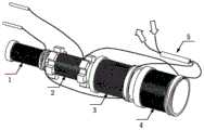
图1是本发明所述一种干涉型高频光纤水听器的装配结构示意图;Fig. 1 is the assembly structure schematic diagram of a kind of interference type high frequency optical fiber hydrophone according to the present invention;
图2是本发明所述一种干涉型高频光纤水听器装配完成后的结构示意图;2 is a schematic structural diagram of an interference type high-frequency optical fiber hydrophone according to the present invention after assembly;
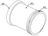
图3是本发明所述第一薄壁空心圆筒1三维结构示意图;3 is a schematic diagram of the three-dimensional structure of the first thin-walled hollow cylinder 1 according to the present invention;
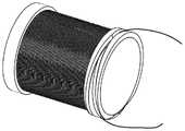
图4是本发明所述第一薄壁空心圆筒1缠绕完光纤后的三维结构示意图;4 is a schematic diagram of the three-dimensional structure of the first thin-walled hollow cylinder 1 according to the present invention after the optical fiber is wound;
图5是本发明所述第二薄壁空心圆筒2三维结构示意图;5 is a schematic diagram of the three-dimensional structure of the second thin-walled
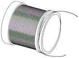
图6是本发明所述第二薄壁空心圆筒2缠绕完光纤后的三维结构示意图;Fig. 6 is the three-dimensional structure schematic diagram of the second thin-walled
图7是本发明所述第三薄壁空心圆筒3三维结构示意图;7 is a schematic diagram of the three-dimensional structure of the third thin-walled
图8是本发明所述第三薄壁空心圆筒3缠绕完光纤后的三维结构示意图;8 is a three-dimensional schematic diagram of the third thin-walled
图9是本发明所述第四薄壁空心圆筒4三维结构示意图;9 is a schematic diagram of the three-dimensional structure of the fourth thin-walled
图10是本发明所述第四薄壁空心圆筒4缠绕完光纤后的三维结构示意图;10 is a schematic diagram of the three-dimensional structure of the fourth thin-walled
图11是本发明所述光纤干涉仪5结构示意图;11 is a schematic structural diagram of the
图12是本发明所述一种干涉型高频光纤水听器实例幅频响应图。FIG. 12 is an example amplitude-frequency response diagram of an interferometric high-frequency fiber optic hydrophone according to the present invention.
附图标记说明:Description of reference numbers:
1:第一薄壁圆筒;2:第二薄壁圆筒;3:第三薄壁圆筒;4:第四薄壁圆筒;5:光纤干涉仪;1: The first thin-walled cylinder; 2: The second thin-walled cylinder; 3: The third thin-walled cylinder; 4: The fourth thin-walled cylinder; 5: Optical fiber interferometer;
101:第一光纤缠绕区;102:第一支撑结构1;103:第一左右螺旋槽;201:第二光纤缠绕区;202:第二支撑结构;203:凹槽;301:第三光纤缠绕区;302:第三支撑结构1;303:第三左右螺旋槽;401:第四光纤缠绕区;402:第四支撑结构1;403:第四左右螺旋槽;501:光入射端口;502:光出射端口;503:3dB耦合器;504:第一光纤干涉臂;505:第一光纤干涉臂;506:第一法拉第旋镜;507:第二法拉第旋镜。101: First fiber winding area; 102: First support structure 1; 103: First left and right helical grooves; 201: Second fiber winding area; 202: Second support structure; 203: Groove; 301: Third fiber winding area; 302: third support structure 1; 303: third left and right helical grooves; 401: fourth fiber winding area; 402: fourth support structure 1; 403: fourth left and right helical grooves; 501: light entrance port; 502: 503: 3dB coupler; 504: first optical fiber interference arm; 505: first optical fiber interference arm; 506: first Faraday rotation mirror; 507: second Faraday rotation mirror.
具体实施方式Detailed ways
为了使本领域的技术人员更好地理解本发明的技术方案,下面结合附图和具体实施例对本发明作进一步详细的描述,需要说明的是,在不冲突的情况下,本申请的实施例及实施例中的特征可以相互组合。In order to make those skilled in the art better understand the technical solutions of the present invention, the present invention will be described in further detail below with reference to the accompanying drawings and specific embodiments. and features of the embodiments may be combined with each other.
图1是本发明一种干涉型高频光纤水听器一实施例的结构示意图,图2是本发明所述一种干涉型高频光纤水听器装配完成后的结构示意图,图3是本发明所述第一薄壁空心圆筒1三维结构示意图,图4是本发明所述第一薄壁空心圆筒1缠绕完光纤后的三维结构示意图,图5是本发明所述第二薄壁空心圆筒2三维结构示意图,图6是本发明所述第二薄壁空心圆筒2缠绕完光纤后的三维结构示意图,图7是本发明所述第三薄壁空心圆筒3三维结构示意图,图8是本发明所述第三薄壁空心圆筒3缠绕完光纤后的三维结构示意图,图9是本发明所述第四薄壁空心圆筒4三维结构示意图,图10是本发明所述第四薄壁空心圆筒4缠绕完光纤后的三维结构示意图,图11是本发明所述光纤干涉仪5结构示意图。1 is a schematic structural diagram of an embodiment of an interference type high-frequency optical fiber hydrophone according to the present invention, FIG. 2 is a schematic structural diagram of an interference type high-frequency optical fiber hydrophone according to the present invention after assembly, and FIG. 3 is a schematic diagram of the present invention. Schematic diagram of the three-dimensional structure of the first thin-walled hollow cylinder 1 according to the present invention, FIG. 4 is a schematic diagram of the three-dimensional structure of the first thin-walled hollow cylinder 1 according to the present invention after winding the optical fiber, and FIG. 5 is the second thin-walled hollow cylinder 1 of the present invention. A schematic diagram of the three-dimensional structure of the
本发明所述一种基于折叠空气腔的干涉型高频光纤水听器,包括4个可嵌套安装的薄壁空心圆筒:带第一光纤缠绕区101与第一支撑结构102的第一薄壁空心圆筒1,带第二光纤缠绕区201与第二支撑结构202的第二薄壁空心圆筒2,带第三光纤缠绕区301与第三支撑结构302的第三薄壁空心圆筒3,以及带第四光纤缠绕区401与第四支撑结构402的第四薄壁空心圆筒4,以及光纤干涉仪5;The interference type high-frequency fiber optic hydrophone based on a folded air cavity according to the present invention includes four thin-walled hollow cylinders that can be nested and installed: a first
所述第一支撑结构102的外径与所述第二薄壁空心圆筒2内径相同,当所述第一薄壁空心圆筒1嵌套进所述第二薄壁空心圆筒2后,在第一薄壁空心圆筒光纤缠绕区101处会形成第一个密封的空气腔;The outer diameter of the
所述第二支撑结构202的外径与所述第三薄壁空心圆筒3内径相同,所述第二支撑结构202上沿圆筒轴向开有6个凹槽202,使得液体可通过凹槽自由流过,当所述第二薄壁空心圆筒2嵌套进所述第三薄壁空心圆筒3后,在第二光纤缠绕区201处形成一个液体可自由流通的液体腔,使得缠绕在第二光纤缠绕区201与第一光纤缠绕区101的光纤干涉仪两臂形成推挽结构,对相同的声压产生相反的形变,以提高探测灵敏度;The outer diameter of the
所述第三支撑结构302的外径与所述第四薄壁空心圆筒4内径相同,当所述第三薄壁空心圆筒3嵌套进所述第四薄壁空心圆筒4后,在第三薄壁空心圆筒光纤缠绕区301处形成第二个密封的空气腔;The outer diameter of the
所述光纤干涉仪5包括光入射端口501、光出射端口502、3dB耦合器503、第一光纤干涉臂504、第二光纤干涉臂505、第一法拉第旋镜506、第二法拉第旋镜507,激光从光纤干涉仪5的光入射端口501入射,经过3dB耦合器503后分为两束激光,分别进入第一光纤干涉臂504和第二光纤干涉臂505,所述第一光纤干涉臂504和第二光纤干涉臂505按照如下所述光纤缠绕方案缠绕在第一薄壁空心圆筒1、第二薄壁空心圆筒2、第三薄壁空心圆筒3、第四薄壁空心圆筒4的光纤缠绕区上以提高传感灵敏度,第一光纤干涉臂504和第二光纤干涉臂505的尾端分别连接第一法拉第旋镜506和第二法拉第旋镜507,以保证两个光纤干涉臂中的光信号反射回原光路,反射回的光信号分别经过第一光纤干涉臂504和第二光纤干涉臂505后再次进入3dB耦合器503后,从与3dB耦合器503相连的光出射端口502出射,通过监测出射光强信号,可测算2个光纤干涉臂传感到的外界声压信号;The
所述第一薄壁空心圆筒1、第三薄壁空心圆筒3以及第四薄壁空心圆筒4均在同一端(例如右端)的支撑结构上分别刻有第一左右螺旋槽103、第三左右螺旋槽303和第四左右螺旋槽403,使得光纤可缠绕进或缠绕出光纤缠绕区;The first thin-walled hollow cylinder 1, the third thin-walled
所述光纤缠绕方案为:薄壁空心圆筒第一光纤干涉臂504从第一法拉第旋镜506一端开始,沿第一薄壁空心圆筒支撑结构102刻有左右螺旋槽一端的左螺旋槽(或右螺旋槽)缠绕进第一光纤缠绕区101,均匀紧密排列缠绕,达到设计层数后从同一端沿右螺旋槽(或左螺旋槽)缠绕出第一光纤缠绕区101后,沿第三薄壁空心圆筒支撑结构302刻有左右螺旋槽一端的左螺旋槽(或右螺旋槽)缠绕进第三光纤缠绕区301,均匀紧密排列缠绕,达到设计层数后从同一端沿右螺旋槽(或左螺旋槽)缠绕出第三光纤缠绕区301后与3dB耦合器503连接;The optical fiber winding scheme is as follows: the first optical
薄壁空心圆筒第二光纤干涉臂505从第二法拉第旋镜507一端开始,沿第二薄壁空心圆筒支撑结构202刻有左右螺旋槽一端的左螺旋槽(或右螺旋槽)缠绕进第二光纤缠绕区201,均匀紧密排列缠绕,达到设计层数后从同一端沿右螺旋槽(或左螺旋槽)缠绕出第二光纤缠绕区201后,沿第四薄壁空心圆筒支撑结构402刻有左右螺旋槽一端的左螺旋槽(或右螺旋槽)缠绕进第四光纤缠绕区401,均匀紧密排列缠绕,达到设计层数后从同一端沿右螺旋槽(或左螺旋槽)缠绕出第四光纤缠绕区401后与3dB耦合器503连接;The thin-walled hollow cylinder second optical
所述第一薄壁空心圆筒1、第二薄壁空心圆筒2、第三薄壁空心圆筒3以及第四薄壁空心圆筒4在完成光纤干涉仪5两光纤干涉臂光纤的缠绕后,按照半径大小依次嵌套在一起,所述光纤干涉仪5第一光纤干涉臂504传感部分的光纤被缠绕在密封空气腔内部,所述光纤干涉仪第二光纤干涉臂505传感部分的光纤被缠绕在液体可自由流通的液体腔内,组成完整的光纤水听器;The first thin-walled hollow cylinder 1, the second thin-walled
图12是本发明所述一种干涉型高频光纤水听器实例幅频响应图。FIG. 12 is an example amplitude-frequency response diagram of an interferometric high-frequency fiber optic hydrophone according to the present invention.
以上所述的具体实施例,对本发明的目的、技术方案和有益效果进行了进一步详细说明,所应理解的是,以上所述仅为本发明的具体实施例而已,并不用于限制本发明,凡在本发明的精神和原则之内,所做的任何修改、等同替换、改进等,均应包含在本发明的保护范围之内。The specific embodiments described above further describe the purpose, technical solutions and beneficial effects of the present invention in detail. It should be understood that the above descriptions are only specific embodiments of the present invention, and are not intended to limit the present invention. Any modification, equivalent replacement, improvement, etc. made within the spirit and principle of the present invention shall be included within the protection scope of the present invention.
Claims (5)
Priority Applications (1)
| Application Number | Priority Date | Filing Date | Title |
|---|---|---|---|
| CN202010111487.6ACN111256807B (en) | 2020-02-24 | 2020-02-24 | A small-size interference-type high-frequency fiber optic hydrophone based on a folded air cavity |
Applications Claiming Priority (1)
| Application Number | Priority Date | Filing Date | Title |
|---|---|---|---|
| CN202010111487.6ACN111256807B (en) | 2020-02-24 | 2020-02-24 | A small-size interference-type high-frequency fiber optic hydrophone based on a folded air cavity |
Publications (2)
| Publication Number | Publication Date |
|---|---|
| CN111256807A CN111256807A (en) | 2020-06-09 |
| CN111256807Btrue CN111256807B (en) | 2020-11-06 |
Family
ID=70954671
Family Applications (1)
| Application Number | Title | Priority Date | Filing Date |
|---|---|---|---|
| CN202010111487.6AActiveCN111256807B (en) | 2020-02-24 | 2020-02-24 | A small-size interference-type high-frequency fiber optic hydrophone based on a folded air cavity |
Country Status (1)
| Country | Link |
|---|---|
| CN (1) | CN111256807B (en) |
Families Citing this family (4)
| Publication number | Priority date | Publication date | Assignee | Title |
|---|---|---|---|---|
| CN112799175B (en)* | 2021-04-14 | 2021-07-02 | 国开启科量子技术(北京)有限公司 | Optical fiber interference device and quantum communication equipment |
| CN113124992A (en)* | 2021-04-21 | 2021-07-16 | 长沙军民先进技术研究有限公司 | Portable photoelectric conversion integrated optical fiber hydrophone and test system thereof |
| CN113295260A (en)* | 2021-05-28 | 2021-08-24 | 珠海任驰光电科技有限公司 | Optical fiber hydrophone based on push-pull structure |
| CN119756554B (en)* | 2025-01-06 | 2025-08-05 | 中国船舶集团有限公司第七一五研究所 | An ultra-fine diameter heterogeneous optical fiber hydrophone and its manufacturing process |
Citations (3)
| Publication number | Priority date | Publication date | Assignee | Title |
|---|---|---|---|---|
| US6160763A (en)* | 1998-12-28 | 2000-12-12 | Sealandaire Technologies, Inc. | Towed array hydrophone |
| CN102080972A (en)* | 2009-11-30 | 2011-06-01 | 西门子公司 | External cavity-type optical fiber Fabry-Perot sensor and system and method for vibration monitoring |
| CN103234619A (en)* | 2013-04-25 | 2013-08-07 | 重庆大学 | Optical fiber Fabry-Perot ultrasound hydrophone and system |
Family Cites Families (7)
| Publication number | Priority date | Publication date | Assignee | Title |
|---|---|---|---|---|
| JP5131497B2 (en)* | 2010-09-22 | 2013-01-30 | 防衛省技術研究本部長 | High water pressure optical fiber hydrophone |
| CN202075031U (en)* | 2011-03-24 | 2011-12-14 | 中国电子科技集团公司第二十三研究所 | Optical fiber grating hydrophone and phase demodulating device thereof |
| CN102374895B (en)* | 2011-09-26 | 2013-02-06 | 中国人民解放军国防科学技术大学 | A large dynamic fiber optic vibration sensor |
| CN103257404B (en)* | 2013-06-04 | 2016-01-13 | 贵阳恒浩光电科技有限公司 | A kind of MEMS Fabry-Perot cavity tunable filter |
| CN108036852B (en)* | 2017-11-03 | 2019-08-13 | 华中科技大学 | A kind of fibre-optical acoustic sensor and multiple spot acoustic detector |
| CN108106713B (en)* | 2017-12-19 | 2021-05-07 | 威海北洋电气集团股份有限公司 | Mandrel type optical fiber hydrophone with air cavity |
| CN109932048B (en)* | 2019-03-14 | 2020-08-25 | 浙江大学 | Interference type optical fiber hydrophone probe based on differential structure |
- 2020
- 2020-02-24CNCN202010111487.6Apatent/CN111256807B/enactiveActive
Patent Citations (3)
| Publication number | Priority date | Publication date | Assignee | Title |
|---|---|---|---|---|
| US6160763A (en)* | 1998-12-28 | 2000-12-12 | Sealandaire Technologies, Inc. | Towed array hydrophone |
| CN102080972A (en)* | 2009-11-30 | 2011-06-01 | 西门子公司 | External cavity-type optical fiber Fabry-Perot sensor and system and method for vibration monitoring |
| CN103234619A (en)* | 2013-04-25 | 2013-08-07 | 重庆大学 | Optical fiber Fabry-Perot ultrasound hydrophone and system |
Also Published As
| Publication number | Publication date |
|---|---|
| CN111256807A (en) | 2020-06-09 |
Similar Documents
| Publication | Publication Date | Title |
|---|---|---|
| CN111256807B (en) | A small-size interference-type high-frequency fiber optic hydrophone based on a folded air cavity | |
| CN111399034B (en) | Hydrophone detection device and method based on low bending loss chirped grating array | |
| CN111103051B (en) | Fiber optic interferometric hydrophone detection system and method | |
| CN214793587U (en) | Microbubble high temperature pressure fiber optic sensor based on vernier effect | |
| CN206618529U (en) | A kind of simple reflective interference-type optical fiber baroceptor | |
| CN110186548A (en) | Fiber F-P sonic transducer and preparation method thereof based on fibre-optical microstructure diaphragm | |
| CN102778306A (en) | Refractive index and temperature sensor of photonic crystal fiber, manufacturing method and measuring system | |
| CN105953958B (en) | All-silica fiber enamel amber pressure sensor | |
| CN113295260A (en) | Optical fiber hydrophone based on push-pull structure | |
| CN112067114B (en) | Vibration measuring device based on double-clad optical fiber | |
| CN105865614B (en) | A kind of novel optical fiber enamel amber ultrasonic hydrophone and preparation method thereof | |
| CN112924082A (en) | High-sensitivity air pressure sensor based on suspension core optical fiber and side hole optical fiber | |
| CN114167084A (en) | Single-optical-fiber three-dimensional acceleration sensing probe and sensor | |
| CN112629743A (en) | Air pressure sensor based on optical fiber double-cavity vernier effect sensitization | |
| CN110849274A (en) | A long-range optical fiber displacement sensor with integrated collimating lens | |
| CN111829645B (en) | Acoustic/vibration monitoring system based on optical fiber sensor | |
| CN107907204A (en) | A kind of deep-sea fibre optic hydrophone | |
| US5726444A (en) | Ultrasonic directional fiber-optic hydrophone | |
| CN108709572A (en) | A kind of integral type micro-displacement optical fiber sensing probe | |
| CN210802682U (en) | A Fiber Optic Interference Hydrophone Detection System | |
| CN205785611U (en) | All-silica fiber enamel amber pressure transducer | |
| CN210603344U (en) | Reflection type large-angle inclined grating optical fiber sensor | |
| CN111721394A (en) | Gas pipeline vibration measurement system and method based on optical fiber sensor | |
| CN218545998U (en) | A Vacuum Gauge Based on Optical Fiber Resonator | |
| CN110057439A (en) | A kind of low quick sensing device of resonance eccentric core fiber sound based on F-P interference |
Legal Events
| Date | Code | Title | Description |
|---|---|---|---|
| PB01 | Publication | ||
| PB01 | Publication | ||
| SE01 | Entry into force of request for substantive examination | ||
| SE01 | Entry into force of request for substantive examination | ||
| GR01 | Patent grant | ||
| GR01 | Patent grant |