CN111255542A - Device and method for detecting dilution rate of engine oil - Google Patents
Device and method for detecting dilution rate of engine oilDownload PDFInfo
- Publication number
- CN111255542A CN111255542ACN201910091775.7ACN201910091775ACN111255542ACN 111255542 ACN111255542 ACN 111255542ACN 201910091775 ACN201910091775 ACN 201910091775ACN 111255542 ACN111255542 ACN 111255542A
- Authority
- CN
- China
- Prior art keywords
- heat shield
- oil
- liquid level
- dilution rate
- resistance wire
- Prior art date
- Legal status (The legal status is an assumption and is not a legal conclusion. Google has not performed a legal analysis and makes no representation as to the accuracy of the status listed.)
- Pending
Links
Images


Classifications
- F—MECHANICAL ENGINEERING; LIGHTING; HEATING; WEAPONS; BLASTING
- F01—MACHINES OR ENGINES IN GENERAL; ENGINE PLANTS IN GENERAL; STEAM ENGINES
- F01M—LUBRICATING OF MACHINES OR ENGINES IN GENERAL; LUBRICATING INTERNAL COMBUSTION ENGINES; CRANKCASE VENTILATING
- F01M11/00—Component parts, details or accessories, not provided for in, or of interest apart from, groups F01M1/00 - F01M9/00
- F01M11/10—Indicating devices; Other safety devices
- F01M11/12—Indicating devices; Other safety devices concerning lubricant level
- F—MECHANICAL ENGINEERING; LIGHTING; HEATING; WEAPONS; BLASTING
- F01—MACHINES OR ENGINES IN GENERAL; ENGINE PLANTS IN GENERAL; STEAM ENGINES
- F01M—LUBRICATING OF MACHINES OR ENGINES IN GENERAL; LUBRICATING INTERNAL COMBUSTION ENGINES; CRANKCASE VENTILATING
- F01M11/00—Component parts, details or accessories, not provided for in, or of interest apart from, groups F01M1/00 - F01M9/00
- F01M11/10—Indicating devices; Other safety devices
- F01M2011/14—Indicating devices; Other safety devices for indicating the necessity to change the oil
- F01M2011/148—Indicating devices; Other safety devices for indicating the necessity to change the oil by considering viscosity
Landscapes
- Engineering & Computer Science (AREA)
- Mechanical Engineering (AREA)
- General Engineering & Computer Science (AREA)
- Lubrication Details And Ventilation Of Internal Combustion Engines (AREA)
Abstract
Translated fromChinese
Description
Translated fromChinese本申请要求于2018年12月03日提交中国专利局、申请号201822019557.6、发明名称为“一种检测机油稀释率的装置”的国内申请的优先权,其全部内容通过引用结合在本申请中。This application claims the priority of the domestic application filed with the China Patent Office on December 03, 2018, the application number is 201822019557.6, and the invention title is "a device for detecting oil dilution rate", the entire contents of which are incorporated into this application by reference.
技术领域technical field
本发明涉及发动机控制技术领域,尤其涉及一种检测机油稀释率的装置和方法。The invention relates to the technical field of engine control, and in particular, to a device and method for detecting oil dilution rate.
背景技术Background technique
当前,轻型车通常在用远后喷的DPF再生方式,该方式的原理是,从喷油器远后喷喷出柴油,喷出的柴油不参与气缸内的燃烧在气缸内滞留一段时间后随废气经过排气门排到后处理的DOC内,在这里与氧气反应放出热量提升DPF(英文全称:Diesel ParticulateFilter,中文全称:柴油颗粒捕集器)前温度从而达到再生的目的。At present, light-duty vehicles usually use the DPF regeneration method of remote injection. The principle of this method is that diesel fuel is injected from the injector at the far rear, and the injected diesel does not participate in the combustion in the cylinder, and stays in the cylinder for a period of time. The exhaust gas is discharged into the post-processed DOC through the exhaust valve, where it reacts with oxygen and releases heat to increase the front temperature of the DPF (English full name: Diesel Particulate Filter, Chinese full name: Diesel Particulate Filter) to achieve the purpose of regeneration.
但是喷入气缸内的柴油,有一部分会附着在气缸壁上并通过与活塞之间的间隙流到机油的机油油底壳,这就机油油底壳内的机油就混入了一定的柴油,会使机油的稀释率升高,粘度值下降,进而影响机油的润滑性能和机油的使用寿命,甚至还有可能出现拉缸的风险。However, part of the diesel injected into the cylinder will adhere to the cylinder wall and flow to the oil pan of the oil through the gap between the piston and the oil. The dilution rate of the oil increases and the viscosity value decreases, which in turn affects the lubricating performance of the oil and the service life of the oil, and even the risk of pulling the cylinder may occur.
现有技术中,通常采用人工观察液位的变化来判断机油稀释率是否发生变化,这样无法实现对机油稀释率的实时监测。In the prior art, the change of the liquid level is usually observed manually to determine whether the oil dilution rate has changed, so that the real-time monitoring of the oil dilution rate cannot be realized.
发明内容SUMMARY OF THE INVENTION
有鉴于此,本发明公开了一种检测机油稀释率的装置,实现了对机油稀释率的实时监测。In view of this, the present invention discloses a device for detecting the oil dilution rate, which realizes real-time monitoring of the oil dilution rate.
本发明公开了一种检测机油稀释率的装置,该装置包括:The invention discloses a device for detecting oil dilution rate, the device comprising:
测量总成和接插件总成;Measuring assembly and connector assembly;
所述测量总成包括:电阻丝、隔热罩、开关;The measuring assembly includes: a resistance wire, a heat shield, and a switch;
所述电阻丝设置在所述隔热罩的内部,且与所述隔热罩的底部相连接,所述开关设置在所述隔热罩底部,所述隔热罩内部通过开关与机油油底壳连通;The resistance wire is arranged inside the heat shield and connected to the bottom of the heat shield, the switch is arranged at the bottom of the heat shield, and the inside of the heat shield is connected to the oil bottom through the switch shell connection;
所述测量总成通过所述接插件总成与电子控制单元ECU相连接。The measuring assembly is connected with the electronic control unit ECU through the connector assembly.
可选的,所述开关为流通阀。Optionally, the switch is a flow valve.
可选的,所述隔热罩的传热系数低于预设阈值。Optionally, the heat transfer coefficient of the heat shield is lower than a preset threshold.
可选的,所述隔热罩为塑料。Optionally, the heat shield is plastic.
可选的,所述电阻丝为热敏电阻。Optionally, the resistance wire is a thermistor.
可选的,所述热敏电阻为正温度系数的热敏电阻。Optionally, the thermistor is a positive temperature coefficient thermistor.
可选的,所述隔热罩的高度与机油油底壳的高度相同。Optionally, the height of the heat shield is the same as the height of the oil pan.
可选的,所述电阻丝的高度高于机油液位的最大值。Optionally, the height of the resistance wire is higher than the maximum value of the oil level.
本发明实施例还公开了一种检测机油稀释率的方法,其中,该方法应用于上述检测机油稀释率的装置,该方法包括:The embodiment of the present invention also discloses a method for detecting the oil dilution rate, wherein the method is applied to the above-mentioned device for detecting the oil dilution rate, and the method includes:
当检测到发动机转速为零时,将所述隔热罩切换为封闭状态;When it is detected that the engine speed is zero, the heat shield is switched to a closed state;
将预设的电流信号作用在所述隔热罩的电阻丝上;Acting the preset current signal on the resistance wire of the heat shield;
检测所述隔热罩内电阻丝的电压值或者电阻值;Detecting the voltage value or resistance value of the resistance wire in the heat shield;
根据预设的电压值与液位的关系,或者电阻值和液位的关系,计算当前的液位值;Calculate the current liquid level value according to the relationship between the preset voltage value and the liquid level, or the relationship between the resistance value and the liquid level;
根据当前液位值和初始液位值,计算机油稀释率。Calculate the oil dilution rate based on the current liquid level value and the initial liquid level value.
可选的,在根据当前液位值和初始液位值,计算机油稀释率后,还包括:Optionally, after calculating the oil dilution rate according to the current liquid level value and the initial liquid level value, it also includes:
打开所述开关,以使所述隔热罩与所述机油油底壳连通。The switch is opened to communicate the heat shield with the oil sump.
本发明实施例公开了一种检测机油稀释率的装置和方法,包括:测量总成和接插件总成;所述测量总成包括:电阻丝、隔热罩、开关;所述电阻丝设置在所述隔热罩的内部,且与所述隔热罩的底部相连接,所述开关设置在所述隔热罩底部,所述隔热罩内部通过开关与机油油底壳连通;所述测量总成通过所述接插件总成与电子控制单元ECU相连接。其中,在隔热罩与机油油底壳连通的情况下,保证了机油油底壳内的液位与隔热罩内的液位相同,并且,在机油液位稳定后,通过隔热罩内电阻丝的电阻的变化,实现对液位变化的检测,进而得到机油稀释率。这样,不仅实现了对机油稀释率的自动化测量,并且实现对机油稀释率的实时监测。The embodiment of the present invention discloses a device and method for detecting oil dilution rate, including: a measuring assembly and a connector assembly; the measuring assembly includes: a resistance wire, a heat shield, and a switch; the resistance wire is arranged in The inside of the heat shield is connected to the bottom of the heat shield, the switch is arranged at the bottom of the heat shield, and the interior of the heat shield communicates with the oil pan through the switch; the measurement The assembly is connected with the electronic control unit ECU through the connector assembly. Wherein, when the heat shield is in communication with the oil pan, it is ensured that the liquid level in the oil pan is the same as the liquid level in the heat shield, and after the oil level is stabilized, the oil passes through the heat shield. The change of the resistance of the resistance wire realizes the detection of the change of the liquid level, and then obtains the oil dilution rate. In this way, not only the automatic measurement of the oil dilution rate is realized, but also the real-time monitoring of the oil dilution rate is realized.
附图说明Description of drawings
为了更清楚地说明本发明实施例或现有技术中的技术方案,下面将对实施例或现有技术描述中所需要使用的附图作简单地介绍,显而易见地,下面描述中的附图仅仅是本发明的实施例,对于本领域普通技术人员来讲,在不付出创造性劳动的前提下,还可以根据提供的附图获得其他的附图。In order to explain the embodiments of the present invention or the technical solutions in the prior art more clearly, the following briefly introduces the accompanying drawings that need to be used in the description of the embodiments or the prior art. Obviously, the accompanying drawings in the following description are only It is an embodiment of the present invention. For those of ordinary skill in the art, other drawings can also be obtained according to the provided drawings without creative work.
图1示出了本发明实施例公开的一种检测机油稀释率的装置的结构示意图;FIG. 1 shows a schematic structural diagram of a device for detecting oil dilution rate disclosed in an embodiment of the present invention;
图2示出了本发明实施例公开的一种测量总成的结构示意图;FIG. 2 shows a schematic structural diagram of a measurement assembly disclosed in an embodiment of the present invention;
图3示出了本发明实施例公开的一种检测机油稀释率的装置的又一结构示意图;3 shows another schematic structural diagram of a device for detecting oil dilution rate disclosed in an embodiment of the present invention;
图4示出了本发明实施例公开的一种检测机油稀释率的方法的流程示意图。FIG. 4 shows a schematic flowchart of a method for detecting oil dilution rate disclosed in an embodiment of the present invention.
具体实施方式Detailed ways
下面将结合本发明实施例中的附图,对本发明实施例中的技术方案进行清楚、完整地描述,显然,所描述的实施例仅仅是本发明一部分实施例,而不是全部的实施例。基于本发明中的实施例,本领域普通技术人员在没有做出创造性劳动前提下所获得的所有其他实施例,都属于本发明保护的范围。The technical solutions in the embodiments of the present invention will be clearly and completely described below with reference to the accompanying drawings in the embodiments of the present invention. Obviously, the described embodiments are only a part of the embodiments of the present invention, but not all of the embodiments. Based on the embodiments of the present invention, all other embodiments obtained by those of ordinary skill in the art without creative efforts shall fall within the protection scope of the present invention.
参考图1-图3,示出了本发明实施例公开的一种检测机油稀释率的装置的结构示意图,在本实施例中,该装置包括:Referring to FIG. 1-FIG. 3, there is shown a schematic structural diagram of a device for detecting oil dilution rate disclosed in an embodiment of the present invention. In this embodiment, the device includes:
测量总成100和插件总成200;Measuring
其中测量总成100通过插件总成200与ECU(英文全称:Electronic Control Unit,中文全称:电子控制单元)相连接。The
其中插件总成200接收ECU的信号,并将测量总成100的信号发送给ECU。The plug-in
参考图2,所述测量总成100包括:电阻丝101、隔热罩102、开关103;Referring to FIG. 2 , the
其中,所述电阻丝101设置在所述隔热罩102的内部且与所述隔热罩102的底部相连接,所述开关103设置在所述隔热罩底部,所述隔热罩内部通过开关与机油油底壳连通;Wherein, the
本实施例中,对机油油底壳内的机油液位进行检测时,并且在ECU处于上电状态下,开关处于关闭状态,其它工况条件下,开关处于打开状态,这样,当开关打开时,测量总成与机油油底壳处于连通状态,隔热罩内的机油液位与机油油底壳内机油液位一致。本实施例中,在正常的驾驶情况下,机油油底壳的液位会发生波动,此时难以准确的测量液位,只有在停车上电的过程中,油底壳静止,液位稳定,可以进行液位的测量。In this embodiment, when the oil level in the oil pan is detected, and when the ECU is powered on, the switch is in the off state, and under other working conditions, the switch is in the open state, so that when the switch is turned on , the measuring assembly is in communication with the oil pan, and the oil level in the heat shield is consistent with the oil level in the oil pan. In this embodiment, under normal driving conditions, the liquid level of the oil pan will fluctuate, and it is difficult to measure the liquid level accurately at this time. Liquid level measurement is possible.
具体的测量过程可以包括:The specific measurement process can include:
在发动机转速为零,且ECU上电的情况下,ECU通过插件总成向测量总成发送一个预设的电流信号,测量总成将电流信号作用于电阻丝上,电阻丝会由于电流的作用而发热,但是浸于机油内的电阻丝产生的热量会被机油冷却,温度不会升高,而处于机油液面上的电阻丝,由于自身温度升高,电阻值会上升。测量总成可以通过插件总成向ECU发送当前的电阻值或者当前电流和电阻值对应的电压值。根据预先通过实验得到的电阻或者电压与机油液位的关系,确定出当前的机油液位。When the engine speed is zero and the ECU is powered on, the ECU sends a preset current signal to the measuring assembly through the plug-in assembly, and the measuring assembly applies the current signal to the resistance wire, and the resistance wire will be affected by the current. However, the heat generated by the resistance wire immersed in the oil will be cooled by the oil, and the temperature will not rise, while the resistance value of the resistance wire on the oil level will rise due to its own temperature rise. The measuring assembly can send the current resistance value or the voltage value corresponding to the current current and the resistance value to the ECU through the plug-in assembly. The current oil level is determined according to the relationship between the resistance or voltage obtained through experiments and the oil level in advance.
将当前的机油液位与初始的机油液位相比较,得到机油稀释率。The current oil level is compared to the initial oil level to obtain the oil dilution ratio.
本实施例中,为了保证隔热罩的隔热性能,隔热罩的传热系数需要低于预设阈值,选用的材料可以为塑料,优选的,可以为传热系数较低的塑料。In this embodiment, in order to ensure the thermal insulation performance of the heat shield, the heat transfer coefficient of the heat shield needs to be lower than a preset threshold, and the selected material may be plastic, preferably, plastic with low heat transfer coefficient.
本实施例中,开关103可以为任何一种形式,优选的可以为流通阀。In this embodiment, the
本实施例中,电阻丝101可以为热敏电阻,具体的,可以为正温度系数的热敏电阻。In this embodiment, the
本实施例中,为了保证隔热罩内的液位与机油油底壳内的液位相同,隔热罩的高度与机油油底壳的高度相同。In this embodiment, in order to ensure that the liquid level in the heat shield is the same as that in the oil pan, the height of the heat shield is the same as the height of the oil pan.
并且,本实施例中,电阻丝的高度高于机油液位的高度。Moreover, in this embodiment, the height of the resistance wire is higher than the height of the oil level.
本实施例中,检测机油稀释率的装置包括:测量总成和接插件总成;所述测量总成包括:电阻丝、隔热罩、开关;所述电阻丝设置在所述隔热罩的内部,且与所述隔热罩的底部相连接,所述开关设置在所述隔热罩底部,所述隔热罩内部通过开关与机油油底壳连通;所述测量总成通过所述接插件总成与电子控制单元ECU相连接。其中,在隔热罩与机油油底壳连通的情况下,保证了机油油底壳内的液位与隔热罩内的液位相同,并且,通过隔热罩内电阻丝的电阻的变化,实现对液位变化的检测,进而得到机油稀释率。这样,不仅实现了对机油稀释率的自动化测量,并且实现对机油稀释率的实时监测。In this embodiment, the device for detecting the oil dilution rate includes: a measuring assembly and a connector assembly; the measuring assembly includes: a resistance wire, a heat shield, and a switch; the resistance wire is arranged on the heat shield inside, and connected with the bottom of the heat shield, the switch is arranged at the bottom of the heat shield, the interior of the heat shield is communicated with the oil pan through the switch; the measuring assembly is connected through the The plug-in assembly is connected with the electronic control unit ECU. Wherein, when the heat shield is in communication with the oil sump, it is ensured that the liquid level in the oil sump is the same as the liquid level in the heat shield, and through the change of the resistance of the resistance wire in the heat shield, Realize the detection of liquid level changes, and then obtain the oil dilution rate. In this way, not only the automatic measurement of the oil dilution rate is realized, but also the real-time monitoring of the oil dilution rate is realized.
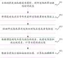
参考图4,示出了本发明实施例公开的一种检测机油稀释率的方法的流程示意图,其中,该方法应用于上述检测机油稀释率的装置中,在本实施例中,该方法包括:Referring to FIG. 4 , a schematic flowchart of a method for detecting oil dilution rate disclosed in an embodiment of the present invention is shown, wherein the method is applied to the above-mentioned device for detecting oil dilution rate. In this embodiment, the method includes:
S401:当检测到发动机转速为零时,将所述隔热罩切换为封闭状态;S401: when it is detected that the engine speed is zero, switch the heat shield to a closed state;
本实施例中,车辆在运行的过程中,即发动机在运行的过程中,在机油油底壳内的机油液位会处于浮动的状态,在这种情况下,无法测量机油的液位。因此,需要保证在发动机转速为零时,且此时ECU上电的情况下,机油稀释率装置对机油稀释率进行测量。In this embodiment, when the vehicle is running, that is, when the engine is running, the oil level in the oil pan will be in a floating state. In this case, the oil level cannot be measured. Therefore, it is necessary to ensure that the oil dilution rate device measures the oil dilution rate when the engine speed is zero and the ECU is powered on at this time.
并且,当发动机转速为零时,如图1所示,可以关闭开关103,这样可以使得隔热罩与机油油底壳处于相对封闭的状态,并且在此时,隔热罩内的机油液位和油底壳内的液位持平,那么通过测量隔热罩内的液位就可以得知油底壳内的液位。Moreover, when the engine speed is zero, as shown in FIG. 1 , the
S402:将预设的电流信号作用在所述隔热罩的电阻丝上;S402: Acting a preset current signal on the resistance wire of the heat shield;
本实施例中,ECU向测量总成发送预设的电流信号,其中,预设的电流信号可以表示为,电流信号的大小是预设的。ECU将电流信号发送给测量总成后,将电流信号作用在隔热罩的电阻丝内。In this embodiment, the ECU sends a preset current signal to the measuring assembly, where the preset current signal can be represented as a preset magnitude of the current signal. After the ECU sends the current signal to the measuring assembly, the current signal acts on the resistance wire of the heat shield.
如图1所示,当开关关闭后,隔热罩内电阻丝有部分浸在机油中,当有电流值作用在电阻丝上时,浸于机油中的部分,产生的热量被机油冷却,温度不会升高。但是,处于液位上的电阻丝会随着温度的升高,电阻值上升。As shown in Figure 1, when the switch is turned off, part of the resistance wire in the heat shield is immersed in the oil. When a current value acts on the resistance wire, the part immersed in the oil will generate heat which is cooled by the oil, and the temperature will not rise. However, the resistance wire at the liquid level will increase in resistance value as the temperature increases.
S403:检测所述隔热罩内电阻丝的电压值或者电阻值;S403: Detect the voltage value or resistance value of the resistance wire in the heat shield;
S404:根据预设的电压值与液位的关系,或者电阻值和液位的关系,计算当前的液位值;S404: Calculate the current liquid level value according to the relationship between the preset voltage value and the liquid level, or the relationship between the resistance value and the liquid level;
本实施例中,技术人员预先根据电阻丝上电压值或者电阻值的变化,经过大量实验得到了,电阻丝上电压值与液位的关系,或者电阻丝上电阻值与液位值的关系。In this embodiment, technicians have obtained the relationship between the voltage value on the resistance wire and the liquid level, or the relationship between the resistance value on the resistance wire and the liquid level value, according to the change of the voltage value or the resistance value on the resistance wire in advance through a large number of experiments.
因此,在隔热罩内的电阻丝的电阻值发生变化后,可以获取该电阻丝的电阻值或者作用在该电阻丝上的电压值,并且根据电压值与液位的关系或者电阻值和液位的关系,得到液位值。Therefore, after the resistance value of the resistance wire in the heat shield changes, the resistance value of the resistance wire or the voltage value acting on the resistance wire can be obtained, and according to the relationship between the voltage value and the liquid level or the resistance value and the liquid level The relationship of the level to get the liquid level value.
其中电压值的计算过程为:电阻丝的电阻值和作用在电阻丝上的电流值的乘积。The calculation process of the voltage value is: the product of the resistance value of the resistance wire and the current value acting on the resistance wire.
S405:根据当前液位值和初始液位值,计算机油稀释率。S405: Calculate the oil dilution rate according to the current liquid level value and the initial liquid level value.
举例说明:假设当前的液位值为H1,初始液位值为H2,机油稀释率为D,则For example: Assuming the current liquid level value is H1 , the initial liquid level value is H2 , and the oil dilution rate is D, then

当得到机油稀释率后,打开开关,使隔热罩与机油油底壳连通。When the oil dilution rate is obtained, turn on the switch to connect the heat shield to the oil sump.
本实施例中,在上述介绍的装置的基础上对机油稀释率进行监测,监测方法包括:当检测到发动机转速为零时,将隔热罩切换为封闭状态;将预设的电流信号作用在所述隔热罩的电阻丝上,获取当前的电阻值或者电压值,并根据预设的的电压值与液位的关系,或者电阻值和液位的关系,计算当前的液位值,并根据当前液位值和初始液位值,计算机油稀释率。这样,通过隔热罩内电阻丝电阻的变化,实现了对机油油底壳内机油液位的变化,进而实现了对机油稀释率的实时监测。In this embodiment, the oil dilution rate is monitored on the basis of the device described above, and the monitoring method includes: when it is detected that the engine speed is zero, switching the heat shield to a closed state; applying a preset current signal to On the resistance wire of the heat shield, the current resistance value or voltage value is obtained, and the current liquid level value is calculated according to the relationship between the preset voltage value and the liquid level, or the relationship between the resistance value and the liquid level. Calculate the oil dilution rate based on the current liquid level value and the initial liquid level value. In this way, the change of the oil level in the oil pan is realized through the change of the resistance of the resistance wire in the heat shield, thereby realizing the real-time monitoring of the oil dilution rate.
需要说明的是,本说明书中的各个实施例均采用递进的方式描述,每个实施例重点说明的都是与其他实施例的不同之处,各个实施例之间相同相似的部分互相参见即可。It should be noted that the various embodiments in this specification are described in a progressive manner, and each embodiment focuses on the differences from other embodiments. For the same and similar parts among the various embodiments, refer to each other Can.
还需要说明的是,在本文中,诸如第一和第二等之类的关系术语仅仅用来将一个实体或者操作与另一个实体或操作区分开来,而不一定要求或者暗示这些实体或操作之间存在任何这种实际的关系或者顺序。而且,术语“包括”、“包含”或者其任何其他变体意在涵盖非排他性的包含,从而使得包括一系列要素的物品或者设备不仅包括那些要素,而且还包括没有明确列出的其他要素,或者是还包括为这种物品或者设备所固有的要素。在没有更多限制的情况下,由语句“包括一个……”限定的要素,并不排除在包括上述要素的物品或者设备中还存在另外的相同要素。It should also be noted that in this document, relational terms such as first and second are used only to distinguish one entity or operation from another, and do not necessarily require or imply those entities or operations There is no such actual relationship or order between them. Furthermore, the terms "comprising", "comprising" or any other variation thereof are intended to encompass a non-exclusive inclusion such that an article or device comprising a list of elements includes not only those elements, but also other elements not expressly listed, Or also include elements inherent to the article or equipment. Without further limitation, an element defined by the phrase "comprising a..." does not preclude the presence of additional identical elements in an article or device that includes the above-mentioned element.
对所公开的实施例的上述说明,使本领域专业技术人员能够实现或使用本发明。对这些实施例的多种修改对本领域的专业技术人员来说将是显而易见的,本文中所定义的一般原理可以在不脱离本发明的精神或范围的情况下,在其它实施例中实现。因此,本发明将不会被限制于本文所示的这些实施例,而是要符合与本文所公开的原理和新颖特点相一致的最宽的范围。The above description of the disclosed embodiments enables any person skilled in the art to make or use the present invention. Various modifications to these embodiments will be readily apparent to those skilled in the art, and the generic principles defined herein may be implemented in other embodiments without departing from the spirit or scope of the invention. Thus, the present invention is not intended to be limited to the embodiments shown herein, but is to be accorded the widest scope consistent with the principles and novel features disclosed herein.
Claims (10)
Translated fromChineseApplications Claiming Priority (2)
| Application Number | Priority Date | Filing Date | Title |
|---|---|---|---|
| CN2018220195576 | 2018-12-03 | ||
| CN201822019557 | 2018-12-03 |
Publications (1)
| Publication Number | Publication Date |
|---|---|
| CN111255542Atrue CN111255542A (en) | 2020-06-09 |
Family
ID=70948993
Family Applications (1)
| Application Number | Title | Priority Date | Filing Date |
|---|---|---|---|
| CN201910091775.7APendingCN111255542A (en) | 2018-12-03 | 2019-01-30 | Device and method for detecting dilution rate of engine oil |
Country Status (1)
| Country | Link |
|---|---|
| CN (1) | CN111255542A (en) |
Cited By (4)
| Publication number | Priority date | Publication date | Assignee | Title |
|---|---|---|---|---|
| CN112160815A (en)* | 2020-09-21 | 2021-01-01 | 北京车和家信息技术有限公司 | Method and device for delaying engine oil dilution and vehicle |
| CN114272503A (en)* | 2021-12-15 | 2022-04-05 | 珠海格力电器股份有限公司 | Water tank, water level reminding method and device thereof, storage medium and hand sterilizer |
| CN115324684A (en)* | 2022-08-18 | 2022-11-11 | 中国第一汽车股份有限公司 | Engine fuel dilution monitoring device and method and automobile |
| CN115596531A (en)* | 2022-09-01 | 2023-01-13 | 中国第一汽车股份有限公司(Cn) | System and method for measuring gas content of engine oil |
Citations (9)
| Publication number | Priority date | Publication date | Assignee | Title |
|---|---|---|---|---|
| CN201292875Y (en)* | 2008-11-12 | 2009-08-19 | 东风襄樊仪表系统有限公司 | Engine oil liquid level sensor |
| EP2123868A1 (en)* | 2008-05-22 | 2009-11-25 | Ford Global Technologies, LLC | Method for determining oil dilution |
| US20100300189A1 (en)* | 2009-05-27 | 2010-12-02 | Denso Corporation | Diagnostic system for variable valve timing control system |
| CN102003248A (en)* | 2010-11-03 | 2011-04-06 | 江阴众和电力仪表有限公司 | Method for measuring lubricating oil level and sensor |
| CN102216572A (en)* | 2009-02-09 | 2011-10-12 | 丰田自动车株式会社 | Device and method for suppressing dilution of oil |
| CN102444445A (en)* | 2011-10-26 | 2012-05-09 | 潍柴动力股份有限公司 | Engine oil liquid level measuring device and method thereof |
| CN105065085A (en)* | 2015-07-31 | 2015-11-18 | 吉林大学 | On-line engine oil quality monitoring system and method adopting multi-sensor information fusion |
| CN108007525A (en)* | 2017-12-26 | 2018-05-08 | 潍柴动力股份有限公司 | A kind of level monitoring device and vehicle fuel level monitor system |
| CN108506114A (en)* | 2017-02-28 | 2018-09-07 | 日立汽车系统(苏州)有限公司 | Reduce the diluted device and method of engine motor oil |
- 2019
- 2019-01-30CNCN201910091775.7Apatent/CN111255542A/enactivePending
Patent Citations (9)
| Publication number | Priority date | Publication date | Assignee | Title |
|---|---|---|---|---|
| EP2123868A1 (en)* | 2008-05-22 | 2009-11-25 | Ford Global Technologies, LLC | Method for determining oil dilution |
| CN201292875Y (en)* | 2008-11-12 | 2009-08-19 | 东风襄樊仪表系统有限公司 | Engine oil liquid level sensor |
| CN102216572A (en)* | 2009-02-09 | 2011-10-12 | 丰田自动车株式会社 | Device and method for suppressing dilution of oil |
| US20100300189A1 (en)* | 2009-05-27 | 2010-12-02 | Denso Corporation | Diagnostic system for variable valve timing control system |
| CN102003248A (en)* | 2010-11-03 | 2011-04-06 | 江阴众和电力仪表有限公司 | Method for measuring lubricating oil level and sensor |
| CN102444445A (en)* | 2011-10-26 | 2012-05-09 | 潍柴动力股份有限公司 | Engine oil liquid level measuring device and method thereof |
| CN105065085A (en)* | 2015-07-31 | 2015-11-18 | 吉林大学 | On-line engine oil quality monitoring system and method adopting multi-sensor information fusion |
| CN108506114A (en)* | 2017-02-28 | 2018-09-07 | 日立汽车系统(苏州)有限公司 | Reduce the diluted device and method of engine motor oil |
| CN108007525A (en)* | 2017-12-26 | 2018-05-08 | 潍柴动力股份有限公司 | A kind of level monitoring device and vehicle fuel level monitor system |
Cited By (6)
| Publication number | Priority date | Publication date | Assignee | Title |
|---|---|---|---|---|
| CN112160815A (en)* | 2020-09-21 | 2021-01-01 | 北京车和家信息技术有限公司 | Method and device for delaying engine oil dilution and vehicle |
| CN112160815B (en)* | 2020-09-21 | 2021-12-17 | 上海理想汽车科技有限公司 | Method and device for delaying engine oil dilution and vehicle |
| CN114272503A (en)* | 2021-12-15 | 2022-04-05 | 珠海格力电器股份有限公司 | Water tank, water level reminding method and device thereof, storage medium and hand sterilizer |
| CN115324684A (en)* | 2022-08-18 | 2022-11-11 | 中国第一汽车股份有限公司 | Engine fuel dilution monitoring device and method and automobile |
| CN115324684B (en)* | 2022-08-18 | 2024-01-16 | 中国第一汽车股份有限公司 | Engine fuel dilution monitoring device and method and automobile |
| CN115596531A (en)* | 2022-09-01 | 2023-01-13 | 中国第一汽车股份有限公司(Cn) | System and method for measuring gas content of engine oil |
Similar Documents
| Publication | Publication Date | Title |
|---|---|---|
| CN111255542A (en) | Device and method for detecting dilution rate of engine oil | |
| JP6202049B2 (en) | Filter failure diagnosis device for internal combustion engine | |
| US10612445B2 (en) | Diagnostic device and sensor | |
| KR101701536B1 (en) | Method and device for monitoring a component arranged in an exhaust gas region of an internal combustion engine | |
| RU151153U1 (en) | EXHAUST GAS DEVICE DEVICE | |
| JP4898843B2 (en) | Measuring device for fine particle concentration in fluid, measuring method and measuring program | |
| JP5240679B2 (en) | Detection device | |
| JP5545502B2 (en) | Exhaust gas purification device for internal combustion engine | |
| EP2321504A1 (en) | Method for estimating soot loading in a diesel particulate filter, and engine and aftertreatment system | |
| CN109681288B (en) | Method, device and system for controlling dilution rate of engine oil | |
| CN105402064B (en) | An integrated filter fuel heating and water level sensing device | |
| US9399943B1 (en) | System and method for detecting particulate filter leakage | |
| US10024260B2 (en) | System for sensing particulate matter | |
| US20160288037A1 (en) | Abnormality diagnosis apparatus for particulate filter | |
| CN114876618B (en) | Method and device for correcting measured value of DPF differential pressure sensor and storage medium | |
| KR102340459B1 (en) | Method for operating a particle sensor | |
| CN112943411B (en) | DPF system, control method and device | |
| CN108547689B (en) | A vehicle control method and control device and a vehicle thereof | |
| JP5924546B2 (en) | Filter failure detection device | |
| AU2014238898A1 (en) | Filter Abnormality Detection Apparatus | |
| CN206409323U (en) | Integrated fuel heater | |
| WO2025066322A1 (en) | Rationality fault detection method for periodic oscillation of gpf differential pressure sensor | |
| CN207647646U (en) | Integrated heater and use its filter and engine | |
| JP6405938B2 (en) | Diagnostic device and sensor | |
| JP2014098363A (en) | Abnormality determination device for filter |
Legal Events
| Date | Code | Title | Description |
|---|---|---|---|
| PB01 | Publication | ||
| PB01 | Publication | ||
| SE01 | Entry into force of request for substantive examination | ||
| SE01 | Entry into force of request for substantive examination | ||
| RJ01 | Rejection of invention patent application after publication | ||
| RJ01 | Rejection of invention patent application after publication | Application publication date:20200609 |