CN111249044A - A stent and placement system - Google Patents
A stent and placement systemDownload PDFInfo
- Publication number
- CN111249044A CN111249044ACN202010203737.9ACN202010203737ACN111249044ACN 111249044 ACN111249044 ACN 111249044ACN 202010203737 ACN202010203737 ACN 202010203737ACN 111249044 ACN111249044 ACN 111249044A
- Authority
- CN
- China
- Prior art keywords
- section
- stent
- tube
- connecting section
- implanter
- Prior art date
- Legal status (The legal status is an assumption and is not a legal conclusion. Google has not performed a legal analysis and makes no representation as to the accuracy of the status listed.)
- Pending
Links
- 238000002513implantationMethods0.000claimsabstractdescription31
- 230000007423decreaseEffects0.000claimsabstractdescription8
- 239000002184metalSubstances0.000claimsdescription45
- 238000006073displacement reactionMethods0.000claimsdescription15
- 230000007704transitionEffects0.000claimsdescription10
- 239000007943implantSubstances0.000claimsdescription7
- 239000000463materialSubstances0.000claimsdescription7
- 238000003466weldingMethods0.000claimsdescription3
- 238000009434installationMethods0.000abstractdescription8
- 230000006835compressionEffects0.000abstractdescription4
- 238000007906compressionMethods0.000abstractdescription4
- 238000001125extrusionMethods0.000abstractdescription3
- 210000003128headAnatomy0.000description24
- 238000010586diagramMethods0.000description14
- 210000000214mouthAnatomy0.000description13
- 230000000694effectsEffects0.000description8
- 238000000034methodMethods0.000description7
- 230000008093supporting effectEffects0.000description7
- 230000000903blocking effectEffects0.000description5
- 208000031481Pathologic ConstrictionDiseases0.000description4
- 230000009471actionEffects0.000description4
- 230000008569processEffects0.000description4
- 208000037804stenosisDiseases0.000description4
- 206010028980NeoplasmDiseases0.000description3
- 230000036262stenosisEffects0.000description3
- 238000001356surgical procedureMethods0.000description3
- VYPSYNLAJGMNEJ-UHFFFAOYSA-NSilicium dioxideChemical compoundO=[Si]=OVYPSYNLAJGMNEJ-UHFFFAOYSA-N0.000description2
- 238000004026adhesive bondingMethods0.000description2
- 230000009286beneficial effectEffects0.000description2
- 238000009954braidingMethods0.000description2
- 201000011510cancerDiseases0.000description2
- 210000001072colonAnatomy0.000description2
- 238000003780insertionMethods0.000description2
- 230000003902lesionEffects0.000description2
- 239000007788liquidSubstances0.000description2
- 239000007769metal materialSubstances0.000description2
- 238000003825pressingMethods0.000description2
- 239000000741silica gelSubstances0.000description2
- 229910002027silica gelInorganic materials0.000description2
- 210000002784stomachAnatomy0.000description2
- 206010051268Anastomotic stenosisDiseases0.000description1
- 208000007217Esophageal StenosisDiseases0.000description1
- 206010030194Oesophageal stenosisDiseases0.000description1
- 208000005718Stomach NeoplasmsDiseases0.000description1
- 230000001154acute effectEffects0.000description1
- 230000003872anastomosisEffects0.000description1
- 238000001816coolingMethods0.000description1
- 238000005520cutting processMethods0.000description1
- 230000003247decreasing effectEffects0.000description1
- 201000010099diseaseDiseases0.000description1
- 208000037265diseases, disorders, signs and symptomsDiseases0.000description1
- 210000001198duodenumAnatomy0.000description1
- 201000004101esophageal cancerDiseases0.000description1
- 210000003238esophagusAnatomy0.000description1
- 239000007888film coatingSubstances0.000description1
- 238000009501film coatingMethods0.000description1
- 206010017758gastric cancerDiseases0.000description1
- 210000001035gastrointestinal tractAnatomy0.000description1
- 230000008595infiltrationEffects0.000description1
- 238000001764infiltrationMethods0.000description1
- 230000037431insertionEffects0.000description1
- 230000003993interactionEffects0.000description1
- 238000010147laser engravingMethods0.000description1
- 230000000149penetrating effectEffects0.000description1
- 230000002093peripheral effectEffects0.000description1
- 229910001220stainless steelInorganic materials0.000description1
- 239000010935stainless steelSubstances0.000description1
- 230000000638stimulationEffects0.000description1
- 201000011549stomach cancerDiseases0.000description1
- 238000006467substitution reactionMethods0.000description1
- 238000009941weavingMethods0.000description1
Images


Classifications
- A—HUMAN NECESSITIES
- A61—MEDICAL OR VETERINARY SCIENCE; HYGIENE
- A61F—FILTERS IMPLANTABLE INTO BLOOD VESSELS; PROSTHESES; DEVICES PROVIDING PATENCY TO, OR PREVENTING COLLAPSING OF, TUBULAR STRUCTURES OF THE BODY, e.g. STENTS; ORTHOPAEDIC, NURSING OR CONTRACEPTIVE DEVICES; FOMENTATION; TREATMENT OR PROTECTION OF EYES OR EARS; BANDAGES, DRESSINGS OR ABSORBENT PADS; FIRST-AID KITS
- A61F2/00—Filters implantable into blood vessels; Prostheses, i.e. artificial substitutes or replacements for parts of the body; Appliances for connecting them with the body; Devices providing patency to, or preventing collapsing of, tubular structures of the body, e.g. stents
- A61F2/82—Devices providing patency to, or preventing collapsing of, tubular structures of the body, e.g. stents
- A61F2/86—Stents in a form characterised by the wire-like elements; Stents in the form characterised by a net-like or mesh-like structure
- A61F2/90—Stents in a form characterised by the wire-like elements; Stents in the form characterised by a net-like or mesh-like structure characterised by a net-like or mesh-like structure
- A—HUMAN NECESSITIES
- A61—MEDICAL OR VETERINARY SCIENCE; HYGIENE
- A61F—FILTERS IMPLANTABLE INTO BLOOD VESSELS; PROSTHESES; DEVICES PROVIDING PATENCY TO, OR PREVENTING COLLAPSING OF, TUBULAR STRUCTURES OF THE BODY, e.g. STENTS; ORTHOPAEDIC, NURSING OR CONTRACEPTIVE DEVICES; FOMENTATION; TREATMENT OR PROTECTION OF EYES OR EARS; BANDAGES, DRESSINGS OR ABSORBENT PADS; FIRST-AID KITS
- A61F2/00—Filters implantable into blood vessels; Prostheses, i.e. artificial substitutes or replacements for parts of the body; Appliances for connecting them with the body; Devices providing patency to, or preventing collapsing of, tubular structures of the body, e.g. stents
- A61F2/82—Devices providing patency to, or preventing collapsing of, tubular structures of the body, e.g. stents
- A61F2/844—Devices providing patency to, or preventing collapsing of, tubular structures of the body, e.g. stents folded prior to deployment
- A—HUMAN NECESSITIES
- A61—MEDICAL OR VETERINARY SCIENCE; HYGIENE
- A61F—FILTERS IMPLANTABLE INTO BLOOD VESSELS; PROSTHESES; DEVICES PROVIDING PATENCY TO, OR PREVENTING COLLAPSING OF, TUBULAR STRUCTURES OF THE BODY, e.g. STENTS; ORTHOPAEDIC, NURSING OR CONTRACEPTIVE DEVICES; FOMENTATION; TREATMENT OR PROTECTION OF EYES OR EARS; BANDAGES, DRESSINGS OR ABSORBENT PADS; FIRST-AID KITS
- A61F2/00—Filters implantable into blood vessels; Prostheses, i.e. artificial substitutes or replacements for parts of the body; Appliances for connecting them with the body; Devices providing patency to, or preventing collapsing of, tubular structures of the body, e.g. stents
- A61F2/95—Instruments specially adapted for placement or removal of stents or stent-grafts
- A61F2/962—Instruments specially adapted for placement or removal of stents or stent-grafts having an outer sleeve
- A61F2/966—Instruments specially adapted for placement or removal of stents or stent-grafts having an outer sleeve with relative longitudinal movement between outer sleeve and prosthesis, e.g. using a push rod
- A61F2002/9665—Instruments specially adapted for placement or removal of stents or stent-grafts having an outer sleeve with relative longitudinal movement between outer sleeve and prosthesis, e.g. using a push rod with additional retaining means
Landscapes
- Health & Medical Sciences (AREA)
- Engineering & Computer Science (AREA)
- Biomedical Technology (AREA)
- Cardiology (AREA)
- Oral & Maxillofacial Surgery (AREA)
- Transplantation (AREA)
- Heart & Thoracic Surgery (AREA)
- Vascular Medicine (AREA)
- Life Sciences & Earth Sciences (AREA)
- Animal Behavior & Ethology (AREA)
- General Health & Medical Sciences (AREA)
- Public Health (AREA)
- Veterinary Medicine (AREA)
- Media Introduction/Drainage Providing Device (AREA)
- Prostheses (AREA)
Abstract
Translated fromChinese
Description
Translated fromChinese技术领域technical field
本发明涉及医疗器械技术领域,具体而言,涉及一种支架及置入系统。The present invention relates to the technical field of medical devices, in particular, to a stent and an implantation system.
背景技术Background technique
在肿瘤病程中,由于肿瘤的直接浸润或压迫引起梗阻,例如在消化道恶性肿瘤的病程中,食管恶性肿瘤造成食管狭窄,胃、十二指肠降部、胰胆系列肿瘤和胃癌手术后吻合口狭窄,结肠恶性肿瘤梗阻和结肠手术后吻合口狭窄等,面对狭窄或梗阻等疾病,目前常用的方法是在狭窄和梗阻部位植入一枚支架,以保证管腔的畅通性。In the course of the tumor, the obstruction is caused by the direct infiltration or compression of the tumor. For example, in the course of the malignant tumor of the digestive tract, the malignant tumor of the esophagus causes esophageal stricture, and the anastomosis of the stomach, descending duodenum, pancreatobiliary series tumors and gastric cancer after surgery Oral stenosis, colon malignant tumor obstruction and anastomotic stenosis after colon surgery, etc. In the face of stenosis or obstruction and other diseases, the commonly used method is to implant a stent at the stenosis and obstruction site to ensure the smoothness of the lumen.
现有的支架根据置入方式的不同分为TTS(Through The Scope)支架和OTW(Over The Wire)支架。OTW支架即支架置入器不经内镜钳道,只经导丝和X射线的辅助观察到达病变位置,因此能够置入外径更大的支架,支架支撑力强、防移位效果好,但是在置入过程中医生和患者长时间暴露在X射线中,对人体造成损害;TTS支架即支架置入器经内镜钳道,通过内镜直视观察置入,从而能够更好地确认支架置入位置,但是TTS置入器外径小,因此其配套支架存在外径小、支撑力差、置入后容易发生位移等问题。Existing stents are divided into TTS (Through The Scope) stents and OTW (Over The Wire) stents according to different placement methods. The OTW stent is the stent implanter that does not go through the endoscopic forceps, but only reaches the lesion location through the auxiliary observation of guide wire and X-ray. Therefore, a stent with a larger outer diameter can be placed, and the stent has strong supporting force and good anti-displacement effect. However, during the implantation process, doctors and patients are exposed to X-rays for a long time, which will cause damage to the human body; the TTS stent, the stent implanter, is placed through the endoscopic forceps and observed through the endoscope, so as to better confirm the placement. The stent is placed in the position, but the outer diameter of the TTS implanter is small, so the supporting stent has problems such as small outer diameter, poor supporting force, and easy displacement after placement.
发明内容SUMMARY OF THE INVENTION
本发明的目的包括,例如,提供了一种支架,其能够更加方便地装入置入器中,有助于通过内镜钳道置入具有更大尺寸的支架,且具有防止移位的功能。Objects of the present invention include, for example, to provide a stent that can be more easily inserted into the implanter, facilitates the placement of stents of larger size through the endoscopic forceps, and has the function of preventing displacement .
本发明的目的还包括,提供了一种置入系统,该置入系统包括上述的支架。Another object of the present invention is to provide an implantation system, which includes the above-mentioned stent.
本发明的实施例可以这样实现:Embodiments of the present invention can be implemented as follows:
本发明的实施例提供了一种支架,所述支架具备相对的远端以及近端,沿所述远端到所述近端的方向上,所述支架包括依次连接的第一大径段、第一连接段、中间段、第二连接段以及第二大径段;An embodiment of the present invention provides a stent, the stent has opposite distal ends and proximal ends, and along the direction from the distal end to the proximal end, the stent includes a first large-diameter section, a first large-diameter section, a a first connecting section, an intermediate section, a second connecting section and a second large diameter section;
沿所述远端到所述近端的方向,所述第一连接段的外径逐渐减小;along the direction from the distal end to the proximal end, the outer diameter of the first connecting segment gradually decreases;
所述中间段、所述第二连接段以及所述第二大径段形成限位台阶,所述限位台阶用于防止移位。The middle section, the second connecting section and the second large diameter section form a limit step, and the limit step is used to prevent displacement.
可选地,所述第一连接段的外壁与所述中间段的外壁之间具有夹角α;所述第二连接段的外壁与所述中间段的外壁之间具有夹角β;Optionally, there is an included angle α between the outer wall of the first connecting section and the outer wall of the intermediate section; there is an included angle β between the outer wall of the second connecting section and the outer wall of the intermediate section;
其中,α-β≥20°Among them, α-β≥20°
可选地,90°<α≤180°。Optionally, 90°<α≤180°.
可选地,115°≤α≤155°。Optionally, 115°≤α≤155°.
可选地,60°≤β≤120°。Optionally, 60°≤β≤120°.
可选地,所述第一连接段呈锥状。Optionally, the first connecting segment is tapered.
可选地,所述第一大径段与所述第一连接段的连接处圆弧过渡。Optionally, an arc transition at the connection between the first large diameter section and the first connecting section.
可选地,所述第一大径段呈圆筒状。Optionally, the first large diameter section is cylindrical.
可选地,所述第二连接段的外壁与所述中间段的外壁之间具有夹角β,80°≤β≤100°。Optionally, there is an included angle β between the outer wall of the second connecting segment and the outer wall of the intermediate segment, 80°≤β≤100°.
可选地,所述第二连接段垂直于所述中间段。Optionally, the second connecting segment is perpendicular to the intermediate segment.
可选地,所述第一大径段、所述第一连接段、所述中间段、所述第二连接段和所述第二大径段均覆膜。Optionally, the first large-diameter section, the first connecting section, the intermediate section, the second connecting section and the second large-diameter section are all covered with a film.
可选地,所述第一大径段、所述第一连接段、所述中间段、所述第二连接段以及所述第二大径段均关于预设轴线对称设置。Optionally, the first large-diameter section, the first connecting section, the intermediate section, the second connecting section, and the second large-diameter section are all symmetrically arranged about a preset axis.
可选地,所述中间段的径向尺寸为R,14mm≤R≤24mm。Optionally, the radial dimension of the middle section is R, 14mm≤R≤24mm.
本发明的实施例还提供了一种置入系统。所述置入系统包括置入器以及上述的支架;所述置入器具有容纳腔,所述支架设置在所述容纳腔内。Embodiments of the present invention also provide an implant system. The implantation system includes an implanter and the above-mentioned bracket; the implanter has a accommodating cavity, and the bracket is arranged in the accommodating cavity.
可选地,所述置入器包括内管、外管和推动件,所述外管套设于所述内管;所述内管包括金属管部,所述金属管部与所述外管之间形成所述容纳腔,所述推动件设置在所述内管与所述外管之间,且所述推动件用于推动位于所述容纳腔内的所述支架。Optionally, the implanter includes an inner tube, an outer tube and a pusher, the outer tube is sleeved on the inner tube; the inner tube includes a metal tube part, the metal tube part and the outer tube The accommodating cavity is formed therebetween, the pushing member is arranged between the inner tube and the outer tube, and the pushing member is used to push the bracket located in the accommodating cavity.
可选地,所述内管的材质为金属。Optionally, the material of the inner tube is metal.
可选地,所述置入器还包括头部,所述头部上设置有相互连通的安装孔与通孔,所述金属管部的远端安装在所述安装孔内,所述通孔与所述内管的内孔连通以形成用于供导丝穿设的通道,所述通孔的径向尺寸小于或者等于所述内孔的径向尺寸。Optionally, the implanter further includes a head, the head is provided with a mounting hole and a through hole that communicate with each other, the distal end of the metal tube is installed in the mounting hole, the through hole is It communicates with the inner hole of the inner tube to form a channel for the guide wire to pass through, and the radial dimension of the through hole is smaller than or equal to the radial dimension of the inner hole.
可选地,所述头部具有对应于所述通孔的第一壁面,所述头部还包括位于所述头部外侧的第二壁面以及连接于所述第一壁面与所述第二壁面之间的连接面,所述连接面为圆弧面。Optionally, the head portion has a first wall surface corresponding to the through hole, and the head portion further includes a second wall surface located outside the head portion and connected to the first wall surface and the second wall surface The connecting surface between them is a circular arc surface.
可选地,所述第二壁面为圆弧面,沿所述头部的远端指向近端的方向,所述第二壁面至所述头部的轴线之间的距离逐渐增大。Optionally, the second wall surface is a circular arc surface, and the distance from the second wall surface to the axis of the head gradually increases along the direction from the distal end of the head to the proximal end.
可选地,所述头部的材质为金属。Optionally, the material of the head is metal.
可选地,所述头部与所述金属管部通过激光焊接固定。Optionally, the head and the metal tube are fixed by laser welding.
可选地,所述头部的近端具有抵接面,所述抵接面用于与所述外管的远端抵接定位。Optionally, the proximal end of the head has an abutment surface, and the abutment surface is used for abutting and positioning with the distal end of the outer tube.
可选地,所述头部还包括凸出所述抵接面设置的卡块,所述卡块与所述抵接面形成定位空间,所述定位空间用于容纳所述外管的远端。Optionally, the head further includes a blocking block disposed protruding from the abutting surface, the blocking block and the abutting surface form a positioning space, and the positioning space is used for accommodating the distal end of the outer tube .
可选地,所述置入器上设置有释放标识。Optionally, a release sign is provided on the inserter.
本发明实施例的支架及置入系统的有益效果包括,例如:The beneficial effects of the stent and the implantation system according to the embodiments of the present invention include, for example:
本发明的实施例提供了一种支架,其具备相对的远端和近端。沿远端到近端的方向上,支架包括依次连接的第一大径段、第一连接段、中间段、第二连接段以及第二大径段。沿远端到近端的方向,第一连接段的外径逐渐减小,因此在对支架进行径向压缩以将支架装入置入器中时,沿第一连接段的轴线,中间段、第一连接段以及第一大径段上各处位于不同轴向位置,因此压缩后第一连接段处的厚度更小,从而有助于减小安装时与置入器的径向挤压力,进而减小支架与置入器之间的摩擦力,使得在不增大置入器内径的前提下能够装入尺寸更大的支架。同时中间段、第二连接段以及第二大径段形成限位台阶,支架置入人体的管腔中后,人体组织向中间段生长从而在管腔的轴向上与限位台阶抵触,进而有助于防止支架移位。Embodiments of the present invention provide a stent having opposing distal and proximal ends. From the distal end to the proximal end, the stent includes a first large diameter section, a first connecting section, an intermediate section, a second connecting section and a second large diameter section which are connected in sequence. From the distal end to the proximal end, the outer diameter of the first connecting section gradually decreases, so when the stent is radially compressed to fit the stent into the implanter, along the axis of the first connecting section, the middle section, The first connecting section and the first large-diameter section are located at different axial positions, so the thickness of the first connecting section after compression is smaller, which helps to reduce the radial extrusion force with the implanter during installation , thereby reducing the frictional force between the stent and the implanter, so that a stent with a larger size can be installed without increasing the inner diameter of the implanter. At the same time, the middle section, the second connecting section and the second large-diameter section form a limit step. After the stent is placed in the lumen of the human body, the human tissue grows toward the middle section and collides with the limit step in the axial direction of the lumen. Helps prevent stent displacement.
本发明的实施例还提供了一种置入系统,该置入系统包括上述的支架,因此也具有能够在不增大置入器内径的基础上实现尺寸更大的支架的置入,特别是尺寸大、同时又可以防止移位的支架的置入。Embodiments of the present invention also provide an implantation system, which includes the above-mentioned stent, and therefore also has the ability to realize the placement of a stent with a larger size without increasing the inner diameter of the implanter, especially Placement of stents that are large in size and at the same time prevent displacement.
附图说明Description of drawings
为了更清楚地说明本发明实施例的技术方案,下面将对实施例中所需要使用的附图作简单地介绍,应当理解,以下附图仅示出了本发明的某些实施例,因此不应被看作是对范围的限定,对于本领域普通技术人员来讲,在不付出创造性劳动的前提下,还可以根据这些附图获得其他相关的附图。In order to illustrate the technical solutions of the embodiments of the present invention more clearly, the following briefly introduces the accompanying drawings used in the embodiments. It should be understood that the following drawings only show some embodiments of the present invention, and therefore do not It should be regarded as a limitation of the scope, and for those of ordinary skill in the art, other related drawings can also be obtained according to these drawings without any creative effort.
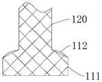
图1为本发明的实施例提供的支架的结构示意图;1 is a schematic structural diagram of a stent provided by an embodiment of the present invention;
图2为本发明的实施例提供的置入系统的局部结构示意图;2 is a schematic diagram of a partial structure of an implantation system provided by an embodiment of the present invention;
图3为本发明的实施例提供的第二种支架的局部结构示意图;3 is a schematic diagram of a partial structure of a second type of stent provided by an embodiment of the present invention;
图4为本发明的实施例提供的第三种支架的局部结构示意图;4 is a schematic partial structure diagram of a third type of stent provided by an embodiment of the present invention;
图5为本发明的实施例提供的支架中第一大径段和第一连接段的连接处的局部结构示意图;5 is a partial structural schematic diagram of the connection between the first large-diameter section and the first connecting section in the stent according to an embodiment of the present invention;
图6为本发明的实施例提供的第四种支架的局部结构示意图;6 is a schematic partial structure diagram of a fourth stent provided by an embodiment of the present invention;
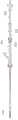
图7为本发明的实施例提供的置入系统中置入器的整体结构示意图;7 is a schematic diagram of the overall structure of an implanter in an implantation system provided by an embodiment of the present invention;
图8为本发明的实施例提供的置入系统中置入器的局部结构示意图;8 is a schematic diagram of a partial structure of an implanter in an implantation system provided by an embodiment of the present invention;
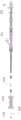
图9为本发明的实施例提供的置入系统中置入器处于释放状态时的结构示意图;9 is a schematic structural diagram of the implanter in the implantation system provided by an embodiment of the present invention when the implanter is in a released state;
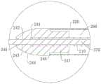
图10为图9中Ⅹ处的局部结构放大图。FIG. 10 is an enlarged view of a part of the structure at X in FIG. 9 .
图标:10-置入系统;100-支架;110-第一杯口段;111-第一大径段;112-第一连接段;113-过渡段;120-中间段;130-第二杯口段;131-第二连接段;132-第二大径段;140-限位台阶;200-置入器;210-内管;211-金属管部;220-外管;230-推动件;231-中管;232-助推管;240-头部;241-安装孔;242-通孔;243-第一壁面;244-第二壁面;245-连接面;246-抵接面;247-卡块;251-第一操作手柄;252-第二操作手柄;253-锁扣;254-锁紧螺母;260-容纳腔;270-导丝。Icons: 10-insertion system; 100-stand; 110-first cup mouth section; 111-first large diameter section; 112-first connecting section; 113-transition section; 120-intermediate section; 130-second cup Mouth section; 131-second connecting section; 132-second large diameter section; 140-limiting step; 200-injector; 210-inner tube; 211-metal tube part; 220-outer tube; 230-pusher ; 231 - middle tube; 232 - booster tube; 240 - head; 241 - mounting hole; 242 - through hole; 243 - first wall surface; 244 - second wall surface; 245 - connecting surface; 246 - abutting surface; 247-block; 251-first operating handle; 252-second operating handle; 253-lock; 254-lock nut; 260-accommodating cavity; 270-guide wire.
具体实施方式Detailed ways
为使本发明实施例的目的、技术方案和优点更加清楚,下面将结合本发明实施例中的附图,对本发明实施例中的技术方案进行清楚、完整地描述,显然,所描述的实施例是本发明一部分实施例,而不是全部的实施例。通常在此处附图中描述和示出的本发明实施例的组件可以以各种不同的配置来布置和设计。In order to make the purposes, technical solutions and advantages of the embodiments of the present invention clearer, the technical solutions in the embodiments of the present invention will be clearly and completely described below with reference to the accompanying drawings in the embodiments of the present invention. Obviously, the described embodiments These are some embodiments of the present invention, but not all embodiments. The components of the embodiments of the invention generally described and illustrated in the drawings herein may be arranged and designed in a variety of different configurations.
因此,以下对在附图中提供的本发明的实施例的详细描述并非旨在限制要求保护的本发明的范围,而是仅仅表示本发明的选定实施例。基于本发明中的实施例,本领域普通技术人员在没有作出创造性劳动前提下所获得的所有其他实施例,都属于本发明保护的范围。Thus, the following detailed description of the embodiments of the invention provided in the accompanying drawings is not intended to limit the scope of the invention as claimed, but is merely representative of selected embodiments of the invention. Based on the embodiments of the present invention, all other embodiments obtained by those of ordinary skill in the art without creative efforts shall fall within the protection scope of the present invention.
应注意到:相似的标号和字母在下面的附图中表示类似项,因此,一旦某一项在一个附图中被定义,则在随后的附图中不需要对其进行进一步定义和解释。It should be noted that like numerals and letters refer to like items in the following figures, so once an item is defined in one figure, it does not require further definition and explanation in subsequent figures.
在本发明的描述中,需要说明的是,若出现术语“上”、“下”、“内”、“外”等指示的方位或位置关系为基于附图所示的方位或位置关系,或者是该发明产品使用时惯常摆放的方位或位置关系,仅是为了便于描述本发明和简化描述,而不是指示或暗示所指的装置或元件必须具有特定的方位、以特定的方位构造和操作,因此不能理解为对本发明的限制。In the description of the present invention, it should be noted that, if the terms "upper", "lower", "inner", "outer", etc. appear, the orientation or positional relationship indicated is based on the orientation or positional relationship shown in the drawings, or It is the orientation or positional relationship that the product of the invention is usually placed in use, only for the convenience of describing the present invention and simplifying the description, rather than indicating or implying that the device or element referred to must have a specific orientation, be constructed and operated in a specific orientation , so it should not be construed as a limitation of the present invention.
此外,若出现术语“第一”、“第二”等仅用于区分描述,而不能理解为指示或暗示相对重要性。In addition, where the terms "first", "second" and the like appear, they are only used to differentiate the description, and should not be construed as indicating or implying relative importance.
需要说明的是,在不冲突的情况下,本发明的实施例中的特征可以相互结合。It should be noted that the features in the embodiments of the present invention may be combined with each other without conflict.
图1为本实施例提供的支架100的结构示意图,图2为本实施例提供的置入系统10的局部结构示意图。请结合参考图1和图2,本实施例提供了一种支架100,相应地,提供了一种置入系统10。需要说明的,在本实施例的描述中,“支架”即能够通过置入器200在内镜直视下经内镜钳道置入人体的管腔的支架。FIG. 1 is a schematic structural diagram of a
置入系统10包括上述的支架100,同时置入系统10还包括置入器200。置入器200内具有用于容纳支架100的容纳腔260,将支架100装入置入器200中后,通过置入器200经内镜钳道将支架100置入人体的管腔中。同理的,由于置入器200在使用过程中,置入器200的前端会伸入人体内,置入器200的后端设置有把手以供医务人员进行操作,因此,相应地,置入器200中各部件靠近前端的部分称为该部件的远端,靠近后端的部分称为该部件的近端。The
支架100具备相对的远端和近端。沿远端到近端的方向上,支架100包括依次连接的第一大径段111、第一连接段112、中间段120、第二连接段131以及第二大径段132。沿远端到近端的方向,第一连接段112的外径逐渐减小,因此在对支架100进行径向压缩以将支架100装入置入器200中时,沿第一连接段112的轴线,中间段120、第一连接段112以及第一大径段111上各处位于不同轴向位置,因此压缩后第一连接段112处的厚度更小,从而有助于减小安装时与置入器200的径向挤压力,进而减小支架100与置入器200之间的摩擦力,使得在不增大置入器200内径的前提下能够装入尺寸更大的支架100,因此能够将较现有TTS支架具有更大尺寸的支架100作为TTS支架,经内镜钳道置入人体内。同时中间段120、第二连接段131以及第二大径段132形成限位台阶140,支架100置入人体的管腔中后,人体组织(即相应管腔的内壁组织)向中间段120生长从而在管腔的延伸方向上与限位台阶140抵触,进而可实现支架100防移位的功能。
需要说明的,在本实施例的描述中,“近端”为置入人体后靠近人体外部的一端,“远端”为置入人体后靠近人体内部的一端,例如在人体的食道中置入支架后,支架的近端为支架靠近口腔的一端,支架的远端为支架靠近胃的一端。It should be noted that in the description of this embodiment, the "proximal end" refers to the end that is close to the outside of the human body after being inserted into the human body, and the "distal end" refers to the end that is close to the interior of the human body after being placed in the human body, for example, it is placed in the esophagus of the human body. After stenting, the proximal end of the stent is the end of the stent that is close to the oral cavity, and the distal end of the stent is the end of the stent that is close to the stomach.
下面对本实施例提供的支架100进行进一步地说明:The
请结合参照图1和图2,在本实施例中,支架100包括依次设置的第一杯口段110、中间段120和第二杯口段130,中间段120呈圆筒状,第一杯口段110和第二杯口段130的径向尺寸均大于中间段120,从而形成哑铃状外形的支架100。具体的,第一杯口段110位于中间段120的远端,第二杯口段130位于中间段120的近端,即第一杯口段110、中间段120和第二杯口段130沿支架100的远端到近端的方向依次设置。同时,第一杯口段110、中间段120和第二杯口段130采用金属丝编织一体成型制成。Please refer to FIG. 1 and FIG. 2 , in this embodiment, the
第一杯口段110包括第一大径段111和第一连接段112,第一连接段112的两端分别与第一大径段111和中间段120连接,第一大径段111的外径大于中间段120的外径,从而通过第一连接段112实现不同外径尺寸之间的连接过渡。具体的,沿支架100的远端到近端的方向(即图1中由下往上的方向),第一连接段112的外径逐渐减小,即第一连接段112的近端和远端沿第一连接段112的轴向间隔设置,需要说明的,在本实施例的描述中,“第一连接段112的外径”指第一连接段112上各处至支架100的轴线之间的距离。The
由于第一大径段111的外径大于中间段120的外径,因此第一连接段112的近端外径小于第一连接段112的远端外径,中间段120、第一连接段112和第一大径段111在轴向上依次设置,因而当支架100受到径向压缩、外形减小以装入置入器200中时,中间段120、第一连接段112和第一大径段111的各处在轴向上依次设置,即中间段120。第一连接段112和第一大径段111在轴向各处无重叠现象,从而有助于减小安装时与置入器200的径向挤压力,进而减小支架100与置入器200之间的摩擦力,使得在不增大置入器200内径的基础上能够装入尺寸更大的支架100。Since the outer diameter of the first large-
请参照图1,在本实施例中,第二杯口段130包括第二连接段131和第二大径段132,第二连接段131的两端分别与第二大径段132和中间段120连接,即沿支架100的远端到近端的方向上,第一大径段111、第一连接段112、中间段120、第二连接段131以及第二大径段132依次连接。Referring to FIG. 1 , in this embodiment, the second
中间段120、第二连接段131以及第二大径段132形成限位台阶140,中间段120与第二连接段131之间形成与限位台阶140对应的限位空间,当支架100置入人体的管腔中后,人体组织向限位空间内生长,从而使该人体组织在管腔的延伸方向上与限位台阶140抵触限位,防止支架100在管腔的延伸方向上发生移位情况。可选地,第二连接段131与第二大径段132的连接处设置弧面圆滑过渡,从而可以减小限位台阶140对人体的刺激、损伤,同时也有助于较大尺寸的支架100更加顺利地装入置入器200中。The
具体的,第二大径段132呈圆筒状,且第二大径段132与中间段120同轴设置,因此第二大径段132和中间段120在如图1所示的平面内投影形成的轮廓线相互平行。且第一大径段111、第一连接段112、中间段120、第二连接段131和第二大径段132均关于预设轴线对称设置,预设轴线即为第一大径段111、中间段120和第二大径段132的轴线所在的直线。Specifically, the second large-
请继续参照图1,在本实施例中,第一连接段112呈锥状,即第一连接段112的外壁为锥面。具体的,第一连接段112的外壁与中间段120的外壁之间具有夹角,即第一连接段112的外壁在如图1所示的平面中所形成轮廓线与中间段120的外壁在如图1所示的平面中所形成的轮廓线交叉形成的夹角,该夹角为α;同理地,第二连接段131的外壁与中间段120的外壁之间也具有夹角,即第二连接段131的外壁在如图1所示的平面中所形成轮廓线与中间段120的外壁在如图1所示的平面中所形成的轮廓线交叉形成的夹角,该夹角为β;α-β≥20°。具体地,90°<α≤180°,通过将α设置为钝角,有助于减小安装时第一连接段112与置入器200的径向挤压力,进而减小支架100与置入器200之间的摩擦力,使得在不增大置入器200内径的基础上能够更加轻易地将大尺寸的支架100装入置入器200中,进而能够将较现有TTS支架具有更大尺寸的支架100作为TTS支架,经内镜钳道置入人体内。进一步地,115°≤α≤155°。可选地,夹角α为115°、135°或155°。可以理解的,在其他实施例中,也可以根据需求,具体设置夹角的具体数值。具体地,60°≤β≤120°。通过对α以及β具体角度值的设置,有助于同时保证支架100的防移位效果以及装入置入器200的便利性。可选地,夹角β为60°、90°或120°。Please continue to refer to FIG. 1 , in this embodiment, the first connecting
为了进一步保证支架100的防移位效果,第二连接段131的外壁与中间段的外壁之间形成夹角β,80°≤β≤100°。在本实施例中,第二连接段131垂直于中间段120,即第二连接段131和中间段120在如图1所示的平面内的投影形成的轮廓线相互垂直,换言之,在本实施例中,β=90°。因此第二连接段131沿中间段120的径向延伸,同时第二连接段131垂直第二大径段132设置。可选地,夹角β也可以设置为80°或100°。需要说明的,在本实施例中第二连接段131垂直中间段120设置,可以理解的,在其他实施例中,也可以将设置为第二连接段131与中间段120之间形成锐角的方式(如图3所示)。In order to further ensure the anti-displacement effect of the
需要说明的,在本实施例中,第一连接段112呈锥状,可以理解的,在其他实施例中,也可以根据需求,具体设置第一连接段112的形状,例如将第一连接段112设置为沿近端到远端的方向上,外径尺寸逐渐增大的弧面(如图4所示)。需要说明的,当第一连接段112设置为弧面时,第一连接段112与中间段120的夹角即为第一连接段112的切线与中间段120的夹角。It should be noted that, in this embodiment, the first connecting
图5为本实施例提供的支架100中第一大径段111和第一连接段112的连接处的局部结构示意图。请参照图5,进一步地,第一大径段111和第一连接段112的连接处圆弧过渡。具体的,第一杯口段110还包括位于第一大径段111和第一连接段112之间的过渡段113,过渡段113在如图4所示的平面所截得的形状为圆弧状,过渡段113的两端分别与第一大径段111和第一连接段112连接,且第一大径段111、过渡段113和第一连接段112通过金属丝编织一体成型。可以理解的,在其他实施例中,也可以根据需求设置第一大径段111和第一连接段112的连接处的结构,例如将第一大径段111的近端直接与第一连接段112的远端连接,从而在第一大径段111和第一连接段112的连接处形成夹角。FIG. 5 is a partial structural schematic diagram of the connection between the first
请结合参照图1和图5,在本实施例中,第一大径段111呈圆筒状,第一大径段111与中间段120同轴设置,因此第一大径段111与中间段120在如图1所示的平面内投影形成的轮廓线相互平行。需要说明的,此处并不对第一大径段111的形状进行限制,可以理解的,在其他实施例中,也可以根据需求设置第一大径段111的形状,例如将第一大径段111设置为在轴向上外径尺寸不断变化的弧形(如图6所示)等,保证第一大径段111的外径尺寸大于中间段120的外径尺寸即可。Please refer to FIG. 1 and FIG. 5 , in this embodiment, the first large-
请参照图1,在本实施例中,中间段120的径向尺寸为R,14mm≤R≤24mm,可选地,中间段120的径向尺寸为14mm、19mm或24mm。第一大径段111的径向尺寸与第二大径段132的尺寸相等,同时第一大径段111和第二大径段132的径向尺寸的具体数值根据现有的中间段120与第一大径段111和第二大径段132的尺寸关系进行设置。Referring to FIG. 1 , in this embodiment, the radial dimension of the
在本实施例中,支架100整体进行覆膜,即组成支架100的第一大径段111、第一连接段112、中间段120、第二连接段131和第二大径段132均覆膜。具体的,该覆膜的具体操作方式可选地,通过将编织形成的金属架体浸入液态的硅胶中,待液态的硅胶将金属架体上的网格孔覆盖后,将金属架体取出,冷却后覆膜完成,从而将金属架体上的网格孔封闭,避免人体组织通过网格孔生长进入支架100内部。可以理解的,在其他实施例中,也可以根据需求仅将第一大径段111、第一连接段112、中间段120、第二连接段131和第二大径段132中的部分覆膜。In this embodiment, the
根据本实施例提供的一种支架100,支架100的工作原理:According to a
首先对支架100进行径向压缩,以将支架100的径向尺寸缩小,从而便于将支架100装入置入器200中,装入时,首先将支架100的近端装入容纳腔260内,在容纳腔260内,支架100与置入器200之间产生径向作用力,进而产生阻碍支架100继续向容纳腔260内进入的摩擦力,待中间段120装入容纳腔260中后,支架100受到的摩擦力由中间段120、第二连接段131和第二大径段132同时产生,此时支架100受到的摩擦力较大,由于第一连接段112沿远端到近端的方向外径逐渐减小,因此可有效降低第一连接段112处产生的摩擦力,进而保证支架100顺利装入置入器200中。First, the
待支架100在置入器200的作用下置入人体的管腔中后,中间段120、第二连接段131以及第二大径段132形成的限位台阶140发挥防移位功能,避免支架100相对管腔移位,同时在支架100近端,即第二大径段132处,可以打夹子以辅助实现防移位功能,防移位效果更好。After the
本实施例提供的一种支架100至少具有以下优点:The
本发明的实施例提供了一种支架100,该支架100通过将第一连接段112设置为沿远端到近端外径逐渐减小的结构,从而减小支架100装入置入器200时的摩擦阻力,有利于在不增大置入器200内径的情况下在置入器200中装入具有更大尺寸的支架100,从而使支架100具有更大的支持力以顺利将人体的管腔狭窄部位撑开,效果更好。同时,支架100的近端设置有限位台阶140,通过限位台阶140与人体组织的相互作用实现防止支架100移位的功能,防移位效果好,进而能够保证治疗效果,降低患者痛苦。通过对第一连接段112与中间段120形成的夹角α以及第二连接段131与中间段120形成的夹角β的具体设置,使得支架100兼顾了较好的防移位效果以及更加容易地装入置入器200的性能。The embodiment of the present invention provides a
请参照图2,本实施例也提供了一种置入系统10,置入系统10包括上述的支架100,同时置入系统10还包括置入器200,置入器200内具有容纳腔260,支架100安装在容纳腔260中,从而随置入器200经内镜钳道进入人体,随后通过操作置入器200释放支架100从而将支架100置入人体管腔中。Referring to FIG. 2, the present embodiment also provides an
图7为本实施例提供的置入系统10中置入器200的整体结构示意图,图8为本实施例提供的置入系统10中置入器200的局部结构示意图。请结合参照图2、图7和图8,在本实施例中,置入器200包括内管210、外管220和推动件230,外管220套设在内管210外,且外管220与内管210同轴间隔设置,从而在内管210和外管220之间形成间隙。内管210的远端设置为金属管部211,该金属管部211与外管220之间形成容纳腔260,即内管210用于与外管220形成容纳腔260的部分采用金属材质制成,通过设置金属管部211,从而在保证具有足够强度的同时可有效减小金属管部211的厚度,进而能够增大容纳腔260的空间尺寸,从而在不增大外管220内径的前提下为支架100提供更大的空间,以在容纳腔260内装入具有更大尺寸的支架100。FIG. 7 is a schematic diagram of the overall structure of the
可选地,内管210的材质为金属,金属管部211即为内管210远端对应形成容纳腔260的部分。具体的,内管210为不锈钢管。可以理解的,在其他实施例中,也可以根据需求具体设置金属管部211的材质,能够在保证强度的前提下减小金属管部211厚度,从而获得具有更大空间的容纳腔260即可。Optionally, the material of the
需要说明的,在本实施例中,内管210整体为金属,金属管部211即为内管210远端对应形成容纳腔260的部分,可以理解的,在其他实施例中,也可以将内管210设置为由金属管与塑料管拼接形成的结构,例如仅将金属管部211设置为金属材质,内管210的其他部分采用塑料制成。It should be noted that, in this embodiment, the
推动件230设置在内管210与外管220之间的间隙处,且与外管220可滑动地配合,使用时,通过推动件230推动支架100,以使支架100相对外管220运动,从而将容纳腔260开启,以实现支架100的释放(如图9所示)。The
进一步地,在本实施例中,内管210包括相互连接的金属管部211和软管部,软管部位于内管210的近端,可以理解的,在其他实施例中,也可以根据需求,将内管210整体设置成由金属材质制成的管状件。具体地,金属管部211与软管部通过胶粘固定连接。Further, in this embodiment, the
请结合参照图7和图9,进一步地,置入器200包括设置在近端的第一操作手柄251和第二操作手柄252,第一操作手柄251位于第二操作手柄252的远端。内管210和推动件230连接在第二操作手柄252上,外管220连接在第一操作手柄251上,使用时,通过操纵第一操作手柄251和第二操作手柄252相对靠近,即可将内管210从外管220中推出,从而将容纳腔260打开,支架100在推动件230的作用下相对外管220运动,当容纳腔260打开时,外管220对支架100施加的径向阻挡力消失,从而使支架100在自身弹性作用下径向扩张,从而恢复原有径向尺寸,从而进行释放。Please refer to FIG. 7 and FIG. 9 , further, the
图10为图9中Ⅹ处的局部结构放大图。请结合参照图2、图9和图10,进一步地,助推件包括中管231以及助推管232,中管231设置在内管210和外管220之间,且中管231为软管,从而便于置入器200在人体内的延伸,助推管232固定连接在第二操作手柄252上,且助推管232的远端与中管231的近端连接,通过助推管232推动中管231运动,进而推动支架100运动。可选地,中管231的近端包裹在助推管232的远端外部,从而实现中管231与助推管232的连接。可以理解的,在其他实施例中,也可以根据需求设置中管231与助推管232的连接方式,例如通过胶粘实现中管231与助推管232的连接。FIG. 10 is an enlarged view of a part of the structure at X in FIG. 9 . Please refer to FIG. 2 , FIG. 9 and FIG. 10 , further, the booster includes a
进一步地,置入器200还包括锁紧螺母254以及锁扣253,第一操作手柄251的近端设置有用于容纳锁扣253的空腔,锁紧螺母254螺接在第一操作手柄251的近端,且助推管232穿过锁紧螺母254以及锁扣253设置,当锁紧螺母254拧紧时,锁扣253在锁紧螺母254的挤压下压缩,从而将助推管232锁紧,达到止推的效果;当锁紧螺母254松开时,锁扣253膨胀,从而将助推管232松开,助推管232能够在推动力的作用下相对外管220运动,从而推动支架100运动,以进行释放。Further, the
请结合参照图7和图8,在本实施例中,置入器200还包括头部240,头部240上设置有相互连通的安装孔241和通孔242。金属管部211的远端安装在安装孔241内,且通孔242与内管210的内孔连通以形成用于供导丝270穿设的通道。通孔242的径向尺寸小于或者等于内孔的径向尺寸,因此金属管部211安装在安装孔241内后,金属管部211远端的端面完全抵接在安装孔241的孔底上,从而避免在置入器200沿导丝270向内运动的过程中,金属管部211的内孔与端面形成的尖角损伤导丝270。可选的,导丝270采用0.63mm导丝270,从而能够给置入器200腾出空间,以在置入器200中放入更强壮、尺寸更大的支架100。Please refer to FIG. 7 and FIG. 8 , in this embodiment, the
进一步地,头部240的材质为金属,通过将头部240设置为金属材质,从而在置入器200穿入人体的过程中,头部240的过狭窄能力强且显影能力强,从而能够更加清楚的观察到头部240的位置,有助于进行支架100的精确释放。可选地,头部240与金属管部211通过激光焊接固定,且头部240与金属管部211平滑连接,从而避免割伤导丝270外皮,有效降低了手术风险。Further, the material of the
进一步地,头部240具有对应于通孔242的第一壁面243,同时,头部240还包括连接面245以及位于头部240外侧的第二壁面244,具体的,第二壁面244为头部240的外周面远端的部分。第一壁面243和第二壁面244通过连接面245连接,即连接面245的两端分别与第一壁面243和第二壁面244连接。连接面245为弧面,从而实现了第一壁面243和第二壁面244的圆滑过渡,避免损伤导丝270以及避免在穿入人体的过程中损伤人体,降低支架置入造成的损伤。Further, the
进一步地,第二壁面244为圆弧面,即在如图8所示的剖面结构中,第二壁面244的截面轮廓为圆弧面。沿头部240的远端指向近端的方向,第二壁面244至头部240的轴线之间的距离逐渐增。Further, the
进一步地,头部240的近端具有抵接面246,抵接面246用于与外管220的远端抵接定位。进一步地,头部240还包括凸出抵接面246设置的卡块247,卡块247与抵接面246形成定位空间以容纳外管220的远端。具体的,卡块247为抵接面246沿远端到近端的方向凸出形成的环形凸起,外管220套设在该环形凸起上,且外管220远端的端面与抵接面246抵触时,实现外管220的轴向限位。Further, the proximal end of the
进一步地,置入器200上还设置有释放标识(图未示出),通过释放标识也更加方便地确定支架100的释放位置,进而实现支架100的精确释放,降低置入系统10的操作难度,以及操作风险。具体地,在外观以及助推管232上分别设置有释放标识,释放标识通过激光雕刻加工产生,在内镜屏幕直视下可清楚观察外管220标识,从而进行支架100的精确释放。Further, the
根据本实施例提供的一种置入系统10,置入系统10的工作原理:According to an
使用时,先将导丝270通过内镜钳道送入病灶部位,然后将装有支架100的置入器200的头部240穿过导丝270,导丝270通过头部240进入内管210的内孔中,并最终从第二操作手柄252穿出。选定支架100的释放位置后,在内窥镜直视下可以看到支架100释放的全过程,也可以在CT下观察显影的头部240来确定支架100的远端位置,保证支架100的精确释放。释放时,首先旋开锁紧螺母254,使锁紧螺母254与第一操作手柄251分离,此时锁扣253膨胀以将包裹住的助推管232释放,助推管232解锁,然后一手握紧第一操作手柄251,一手握紧第二操作手柄252并缓慢推送,从而通过中管231的远端将置入器200中的支架100推出,支架100缓慢释放。In use, the
本实施例提供的一种置入系统10至少具有以下优点:The
本发明的实施例提供的置入系统10包括上述的支架100,因此也具有能够在不增大置入器200内径的情况下在置入器200中装入具有更大尺寸的支架100,从而使支架100具有更大的支持力以顺利将人体的管腔狭窄部位撑开,支撑效果更好,而且防移位效果好的有益效果。同时置入系统10的置入器200通过在内管210设置金属管部211,使得在保证强度的前提下减小金属管部211厚度,从而获得具有更大空间的容纳腔260,进而能够在容纳腔260中装入具有较大尺寸的支架100,进而有效保证支架100具有足够的支撑力。The
以上所述,仅为本发明的具体实施方式,但本发明的保护范围并不局限于此,任何熟悉本技术领域的技术人员在本发明揭露的技术范围内,可轻易想到的变化或替换,都应涵盖在本发明的保护范围之内。因此,本发明的保护范围应以所述权利要求的保护范围为准。The above are only specific embodiments of the present invention, but the protection scope of the present invention is not limited thereto. Any person skilled in the art who is familiar with the technical scope disclosed by the present invention can easily think of changes or substitutions. All should be included within the protection scope of the present invention. Therefore, the protection scope of the present invention should be based on the protection scope of the claims.
Claims (24)
Translated fromChinesePriority Applications (2)
| Application Number | Priority Date | Filing Date | Title |
|---|---|---|---|
| CN202010203737.9ACN111249044A (en) | 2020-03-20 | 2020-03-20 | A stent and placement system |
| PCT/CN2021/077954WO2021185046A1 (en) | 2020-03-20 | 2021-02-25 | Stent and placement system |
Applications Claiming Priority (1)
| Application Number | Priority Date | Filing Date | Title |
|---|---|---|---|
| CN202010203737.9ACN111249044A (en) | 2020-03-20 | 2020-03-20 | A stent and placement system |
Publications (1)
| Publication Number | Publication Date |
|---|---|
| CN111249044Atrue CN111249044A (en) | 2020-06-09 |
Family
ID=70942058
Family Applications (1)
| Application Number | Title | Priority Date | Filing Date |
|---|---|---|---|
| CN202010203737.9APendingCN111249044A (en) | 2020-03-20 | 2020-03-20 | A stent and placement system |
Country Status (2)
| Country | Link |
|---|---|
| CN (1) | CN111249044A (en) |
| WO (1) | WO2021185046A1 (en) |
Cited By (5)
| Publication number | Priority date | Publication date | Assignee | Title |
|---|---|---|---|---|
| CN111888060A (en)* | 2020-09-02 | 2020-11-06 | 南微医学科技股份有限公司 | A stent, implanter and medical device |
| CN112120838A (en)* | 2020-09-30 | 2020-12-25 | 南微医学科技股份有限公司 | A kind of silicone stent, implantation system and manufacturing method |
| WO2021185046A1 (en)* | 2020-03-20 | 2021-09-23 | 南微医学科技股份有限公司 | Stent and placement system |
| CN114631918A (en)* | 2022-03-14 | 2022-06-17 | 江苏博朗森思医疗器械有限公司 | Adjustable bracket system |
| CN116211561A (en)* | 2023-01-09 | 2023-06-06 | 上海市第一人民医院 | Partial tectorial membrane support of biliary pancreatic duct drainage Notes art |
Citations (6)
| Publication number | Priority date | Publication date | Assignee | Title |
|---|---|---|---|---|
| CN1321520A (en)* | 2001-05-24 | 2001-11-14 | 茅爱武 | Gastrointestinal tract support and its preparation process |
| US20030208263A1 (en)* | 1994-05-19 | 2003-11-06 | Burmeister Paul H. | Tissue supporting devices |
| CN2910150Y (en)* | 2006-04-27 | 2007-06-13 | 南京微创医学科技有限公司 | Non-blood vessel coated stand able to prevent complication |
| CN104434354A (en)* | 2015-01-08 | 2015-03-25 | 蒋军红 | Stent placement device |
| CN205007072U (en)* | 2015-08-05 | 2016-02-03 | 李强 | Hourglass form metal tectorial membrane support of narrow usefulness of air flue |
| CN212066944U (en)* | 2020-03-20 | 2020-12-04 | 南微医学科技股份有限公司 | A stent and placement system |
Family Cites Families (1)
| Publication number | Priority date | Publication date | Assignee | Title |
|---|---|---|---|---|
| CN111249044A (en)* | 2020-03-20 | 2020-06-09 | 南微医学科技股份有限公司 | A stent and placement system |
- 2020
- 2020-03-20CNCN202010203737.9Apatent/CN111249044A/enactivePending
- 2021
- 2021-02-25WOPCT/CN2021/077954patent/WO2021185046A1/ennot_activeCeased
Patent Citations (6)
| Publication number | Priority date | Publication date | Assignee | Title |
|---|---|---|---|---|
| US20030208263A1 (en)* | 1994-05-19 | 2003-11-06 | Burmeister Paul H. | Tissue supporting devices |
| CN1321520A (en)* | 2001-05-24 | 2001-11-14 | 茅爱武 | Gastrointestinal tract support and its preparation process |
| CN2910150Y (en)* | 2006-04-27 | 2007-06-13 | 南京微创医学科技有限公司 | Non-blood vessel coated stand able to prevent complication |
| CN104434354A (en)* | 2015-01-08 | 2015-03-25 | 蒋军红 | Stent placement device |
| CN205007072U (en)* | 2015-08-05 | 2016-02-03 | 李强 | Hourglass form metal tectorial membrane support of narrow usefulness of air flue |
| CN212066944U (en)* | 2020-03-20 | 2020-12-04 | 南微医学科技股份有限公司 | A stent and placement system |
Cited By (7)
| Publication number | Priority date | Publication date | Assignee | Title |
|---|---|---|---|---|
| WO2021185046A1 (en)* | 2020-03-20 | 2021-09-23 | 南微医学科技股份有限公司 | Stent and placement system |
| CN111888060A (en)* | 2020-09-02 | 2020-11-06 | 南微医学科技股份有限公司 | A stent, implanter and medical device |
| CN111888060B (en)* | 2020-09-02 | 2025-07-11 | 南微医学科技股份有限公司 | A stent, an implant and a medical device |
| CN112120838A (en)* | 2020-09-30 | 2020-12-25 | 南微医学科技股份有限公司 | A kind of silicone stent, implantation system and manufacturing method |
| CN114631918A (en)* | 2022-03-14 | 2022-06-17 | 江苏博朗森思医疗器械有限公司 | Adjustable bracket system |
| CN114631918B (en)* | 2022-03-14 | 2025-08-01 | 江苏博朗森思医疗器械有限公司 | Adjustable bracket system |
| CN116211561A (en)* | 2023-01-09 | 2023-06-06 | 上海市第一人民医院 | Partial tectorial membrane support of biliary pancreatic duct drainage Notes art |
Also Published As
| Publication number | Publication date |
|---|---|
| WO2021185046A1 (en) | 2021-09-23 |
Similar Documents
| Publication | Publication Date | Title |
|---|---|---|
| CN111249044A (en) | A stent and placement system | |
| US10071231B2 (en) | Medical instrument and medical system | |
| JP4668174B2 (en) | Medical device optical delivery instrument, deployment apparatus and method | |
| EP1890656B1 (en) | Delivery device with viewing window and associated method | |
| JP4471973B2 (en) | Bifurcated medical device supply apparatus and method | |
| JP4648704B2 (en) | Stent delivery system and its use. | |
| US7608099B2 (en) | Medical appliance delivery apparatus and method of use | |
| JP6261339B2 (en) | Apparatus and method for placement of a graft or graft system | |
| US20070043421A1 (en) | Delivery device with shortened inner tube and associated method | |
| US20070162047A1 (en) | Apparatus and method for colonoscopic appendectomy | |
| JP6255101B2 (en) | Elastic band ligation device with integrated obturator and hemorrhoid treatment method | |
| JP6255102B2 (en) | Elastic band ligation device with locking mechanism and hemorrhoid treatment method | |
| JP6255103B2 (en) | Elastic band ligation device with pinching prevention function and hemorrhoid treatment method | |
| US11701498B2 (en) | Guide wire gripping unit | |
| CN109771111B (en) | Push system of self-expansion support | |
| BR102019016190A2 (en) | STENT APPLICATION WITH EXPANSION ASSISTANCE APPLICATION WIRE | |
| JP5027135B2 (en) | Double metal stent introducer | |
| CN212066944U (en) | A stent and placement system | |
| WO2021166156A1 (en) | Stent delivery system, endoscope system, and stenting method | |
| JPH1156753A (en) | Appliance for endoscope | |
| JPWO2003092782A1 (en) | Indwelling tube guide device | |
| JPH08280815A (en) | Catheter for stent delivery | |
| US20240245539A1 (en) | Stent and stent delivery system | |
| US20220387202A1 (en) | Stent delivery system, endoscope system, and stent indwelling method | |
| JPH0213006Y2 (en) |
Legal Events
| Date | Code | Title | Description |
|---|---|---|---|
| PB01 | Publication | ||
| PB01 | Publication | ||
| SE01 | Entry into force of request for substantive examination | ||
| SE01 | Entry into force of request for substantive examination |